


Abstract
This study develops a graded-compliance, metal-packaged fiber Bragg grating (FBG) strain sensor for cryogenic structural health monitoring of metallic propellant tanks and pipelines on reusable launch vehicles (RLVs). The serially connected frame enables customizable sensitivity and expands the effective measurement range via strain desensitization for large-magnitude cryogenic strains. This design reduces interfacial shear stress and improves long-term stability under cyclic cryogenic loads, while glass brazing fixation avoids the failures associated with organic adhesives. The ground characterizations down to 77 K show high linearity (R2 > 0.998) over −4000 to 6000 με. The tensile sensitivity decreases by approximately 4.3% from room temperature to 77 K, with a tension–compression sensitivity discrepancy of 2.4% under cryogenic conditions. The limited sensitivity drift across 77 K–123 K and favorable batch consistency support a unified full-temperature-range sensitivity calculation method, reducing the onboard computational burden. Within the cryogenic operating range of 77 K–123 K, the maximum full-scale error is ±1.01%. Batch-produced sensors have passed environmental qualification tests, and units from different batches were deployed in three independent RLV flight campaigns in 2024, 2025, and 2026. Continuous and stable strain signals were obtained during ground propellant loading and in-flight phases under severe thermo-mechanical loads, consistent with the theoretical predictions.
1. Introduction
Reusable launch vehicles are designed to reduce access-to-space costs through multiple flight cycles. The cryogenic propellant tank is a critical subsystem, serving as both a primary load-bearing structure and an energy-storage vessel. During repeated launch-and-reentry missions, these tanks experience extreme thermal cycling, ranging from cryogenic propellant temperatures to ambient conditions or aerodynamic heating, together with persistent thermo-mechanical coupling loads. Guaranteeing the structural integrity of tank shells, welds, and pipelines under these conditions is essential for safe reusability. This motivates the demand for robust structural health monitoring (SHM) systems. Among the available sensing technologies, FBG sensors are a strong candidate for cryogenic tank monitoring, owing to their electromagnetic interference immunity, low weight, and multiplexing capability along a single optical fiber.
Research on cryogenic fiber Bragg grating (FBG) sensing has intensified over the past two decades, driven by the need for long-term structural health monitoring in harsh cryogenic environments. Recent reviews have summarized the advances in cryogenic FBG temperature-sensing research [1], while earlier work has addressed sensor technologies for integrated vehicle health management in aerospace applications [2]. Experimental studies have demonstrated FBG-based strain monitoring of filament-wound composite tanks [3], real-time strain measurement on cryogenic tanks [4], and multiplexed FBG temperature sensing in CFRP structures under cryogenic conditions [5]. These studies show that cryogenic FBG sensing has matured considerably. However, most of these studies address only isolated technical aspects rather than evaluating the complete sensor system under flight-like conditions.
Previous studies have established the foundational capabilities of FBGs in cryogenic conditions. Ludbrook et al. [6] and Huang et al. [7] verified the temperature–strain sensing performance of FBGs at 77 K, while Li et al. [8] and Yang et al. [9] achieved measurements in liquid helium (~5 K) through specialized packaging. From an engineering perspective, notable progress has been made in practical applications: Allison et al. [10] monitored the cyclic strain on composite tank Y joints using distributed FBGs, González del Val et al. [11] employed FBGs for microcrack detection, and Zhang et al. [12] and Zhu et al. [13] applied FBG systems to ground filling tests of rocket tanks. These studies indicate that FBG sensing shows promise for cryogenic tank and structure monitoring, supporting its further adoption in related engineering applications.
However, a critical research gap remains regarding the systematic evaluation of FBG sensors for flight-ready, reusable scenarios. While previous studies have demonstrated their basic sensing capabilities, few have systematically examined the large dynamic measurement range, long-term reliability under severe thermal cycling, and tension–compression sensitivity asymmetry of FBG sensors under realistic flight-like environments. Most existing validations are limited to short-term laboratory tests or static ground conditions, and comprehensive data on how sensor performance evolves over multiple reuse cycles remain scarce.
To bridge this gap, this study proposes a metal-packaged FBG strain sensor featuring a graded-compliance design for cryogenic structural health monitoring. Its serially connected compliant frame actively attenuates the strain and mechanically decouples the FBG from the external mounting interface, thereby mitigating adhesive degradation induced by cryogenic thermal cycling and preserving measurement fidelity under cryogenic service conditions. Building on our group’s prior flight-qualified FBG hardware, this work extends the sensing technology from ambient-condition operation to extreme cryogenic service environments. Compared with our earlier flight-proven systems, this study adopts a unified full-temperature-range sensitivity calculation method to reduce the onboard computational burden and calibration workload. The sensor’s performance and engineering applicability are validated through a comprehensive ground calibration and multiple flight campaigns, providing a flight-validated structural health monitoring solution for cryogenic metallic propellant tanks and pipelines on reusable launch vehicles.
2. Materials and Methods
2.1. FBG Measurement Principle
The reflection center wavelength of an FBG drifts with changes in perceived physical quantities. The relationship between the center wavelength λB, temperature T, and strain ε is given by
where αf is the thermal expansion coefficient of the optical fiber, ξ is the thermo-optic coefficient of the optical fiber, and Pe is the effective elastic-optic coefficient of the optical fiber [14].
Equation (1) shows that FBG sensors are sensitive to both strain and temperature; established compensation strategies have been reviewed in [15,16,17]. Under cryogenic conditions, this cross-sensitivity gives rise to two distinct effects: (i) thermal zero-point wavelength drift, i.e., the Bragg wavelength shifts with temperature even in the absence of external mechanical loading, due to thermal effects in the optical fiber and its packaging; and (ii) temperature-dependent strain sensitivity, i.e., the relationship between the applied strain and wavelength shift varies over the operating temperature range, as also reported for bonded FBG configurations under cryogenic conditions [18]. The latter effect has received comparatively less attention in cryogenic sensing applications.
In this work, the temperature effects in FBG strain measurement are compensated for through two complementary measures. Zero-point drift is mitigated by performing zero-strain calibration on a coupon matched to the launch vehicle’s structural material, and by using a co-located FBG temperature sensor to provide real-time local temperature readings during operation for subtraction of thermally induced wavelength shifts. Beyond zero-point compensation, this study focuses on the temperature dependence of strain sensitivity. This dependence is addressed through the graded-compliance metal packaging, which introduces a controlled thermo-mechanical coupling between the FBG and the host structure to modify the apparent temperature dependence of the strain response, and the residual variation is quantified through multi-temperature calibration. The resulting sensor is evaluated through ground calibration and flight testing, demonstrating its potential for structural health monitoring of cryogenic components in reusable launch vehicles.
2.2. Compliant Metal Packaging Design for Reusable Cryogenic Tanks
Reusable launch vehicles require metallic cryogenic tanks to withstand repeated thermal cycling between ambient and cryogenic temperatures. The direct adhesive mounting of FBGs on these metallic tank structures suffers from inherent limitations. The strain transfer performance of adhesively mounted FBGs is strongly dependent on geometric parameters of the adhesive layer, such as thickness and length, and material properties of the adhesive layer [19]. Coefficient of thermal expansion (CTE) mismatches across the polymeric adhesive, silica fiber and metallic substrate induce substantial residual thermal stress at the bond interfaces [20,21]. Under repeated thermal cycling, such stresses trigger progressive debonding, microcracking, and creep within the adhesive layer. These defects further induce spectral chirping, baseline drift or loss of measurement.
To address these limitations, this study proposes a graded-compliance metal-packaged FBG sensor. This graded-compliance design is realized by serially assembling flexible outer frames together with a stiffer central frame, creating a discrete compliance gradient along the axial load-transfer path. The sensor uses a commercially available femtosecond-inscribed FBG on a standard single-mode fiber, with a center wavelength near 1550 nm and reflectivity of approximately 50%, protected by a polyimide (PI) coating. Prior to brazing, the PI coating at welding positions is thermally stripped. A commercial low-temperature glass brazing solder for optical fiber is used to secure the fiber onto the metallic frame, with the brazing temperature maintained at approximately 623 K. This assembly method avoids organic adhesive around the grating region. In this design, the FBG is point-fixed in the metal package using glass brazing solder, which achieves adhesive-free bonding between the silica fiber and metallic frame and eliminates organic adhesive failure risks at cryogenic temperatures, ensuring that the fiber Bragg grating is completely isolated from any adhesive contact.
The sensor assembly attaches to the monitored structure only via its two end fixation regions. This structural configuration effectively mechanically decouples the optical sensing element from the external mounting interface. Even if microcracks form in the external mounting adhesive under thermo-mechanical cycling, or adhesive inhomogeneities occur from installation imperfections, the FBG can still function normally with only minor sensitivity deviations. Furthermore, the standardized metal housing enables high-precision batch manufacturing, ensuring high unit-to-unit consistency and facilitating efficient batch calibration. This design supports non-destructive disassembly to extend sensor service life. It provides a measurement solution for metallic aerospace components, such as liquid propellant tanks, where reliable long-term monitoring is essential.
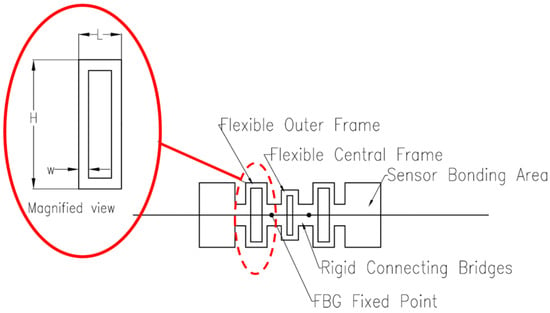
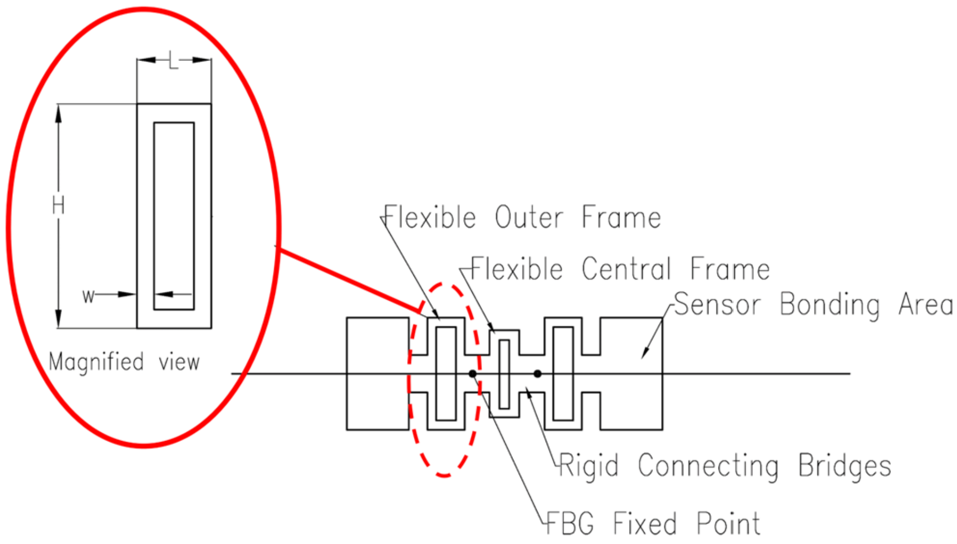
In aerospace hardware, including propellant tanks and engine structures of RLVs, sensors are exposed to broad temperature variations and large-magnitude structural strains. The proposed structure leverages differential compliance to realize tunable strain sensitivity. For the cryogenic large-strain application targeted in this work, a strain-desensitization operating mode is adopted. As illustrated in Figure 1, the assembly consists of two high-compliance outer frames, a low-compliance central frame (for the strain desensitization mode), and rigid connecting bridges arranged in series. The overall configuration of the proposed graded-compliance metal-packaged FBG strain sensor is illustrated in Figure 1. Figure 1 shows the schematic of its serial frame architecture, composed of high-compliance outer frames and a low-compliance central frame together with rigid connecting bridges. The inset magnified view highlights a single frame unit, where L, w, and H denote the horizontal length, rod width, and vertical height of the frame segment, respectively. All geometric parameters involved in the above theoretical derivation are annotated in the inset of Figure 1.
Figure 1.
Schematic diagram of the graded-compliance metal-packaged FBG strain sensor. Inset shows a magnified view of a single frame unit with annotated geometric parameters.
The total axial deformation of the serially connected frame assembly ∆total is equal to the sum of the axial deformation of the outer frames ∆o and the axial deformation of the central frame ∆c:
∆total = ∆o1 + ∆c + ∆o2 = ∆c + 2∆o
When the monitored structure deforms, a tensile force F acts on the sensor along the optical fiber axis. This force loads both the central and outer frames. Compliance, defined as the ratio of axial deformation to the applied axial tensile force, is given by
The total deformation is described using the compliance of each component:
∆total = F(Cc + 2Co)
In this theoretical model, the FBG is fixed to two sides of the central frame and only measures the central frame deformation:
∆FBG = ∆c = F⋅Cc
The strain distribution coefficient β is defined as
The linear strain reads as
Substitute Equation (7) into Equation (6):
Insert Equations (4) and (5) into Equation (8):
Let k denote the compliance ratio of the central frame to the outer frame:
Let m denote the fixed-end length ratio, i.e., the ratio of FBG fixed-support length to the sensor effective length:
The strain distribution coefficient β is calculated as
The strain distribution coefficient β is inversely proportional to k and m. Structural optimization is carried out to achieve a target value of β for strain desensitization. Tuning k and m enables sensor adaptation for different positions of reusable launch vehicles, and this desensitizing design is well-suited for cryogenic propellant systems subjected to large structural strains.
Since the compliance ratio k is determined by the compliance of individual frame units, the frame compliances Cc and Co are fundamentally governed by the geometric dimensions of frame components. To further reveal the geometric origin of the frame compliances Cc and Co contained in the compliance ratio k, an analytical mechanical model of a single flexible frame is established. The frame structure is simplified as a combination of horizontal tension beams and vertical bending beams, where the horizontal beams mainly undergo axial tension and the vertical beams dominate bending deformation. Ignoring the minor deformation components, the total compliance of a single frame unit is superimposed by vertical beam bending compliance and horizontal beam tensile compliance:
The vertical beam is simplified as a fixed–fixed beam subjected to a central transverse load, and its mid-point deflection is obtained from classical beam bending theory:
where H is the vertical beam height, E denotes Young’s modulus, and I is the cross-sectional moment of inertia:
where t is the structural thickness and w is the beam width. The bending compliance of a single vertical beam is derived as
The axial tensile compliance of the horizontal beam is expressed as
where L denotes the horizontal beam length. Substituting the individual compliance components yields the total compliance of a single frame structure:
Frame compliance is most sensitive to the vertical beam height H, owing to its cubic term in the bending deformation expression. The beam width w and horizontal beam length L serve as secondary tuning parameters, while the structural thickness t remains constant for both the inner and outer frames and is not treated as an optimization variable. Reducing the vertical height and increasing the beam width of the central frame can effectively reduce Cc, decrease the compliance ratio k, and thus improve the strain desensitization performance. All geometric parameters involved in the above derivation are annotated in the magnified structural view in Figure 1.
2.3. Structural Optimization and Simulation Verification
Based on the principle of strain desensitization design, geometric optimization was performed on the packaging structure to achieve stable bidirectional tensile–compressive strain measurement. The final key geometric parameters of the sensor, obtained after optimization, are listed in Table 1, ensuring that the compliance of the outer frame exceeds that of the central frame, coupled with an appropriate k value to ensure β < 1.
Table 1.
Sensor structural parameters.
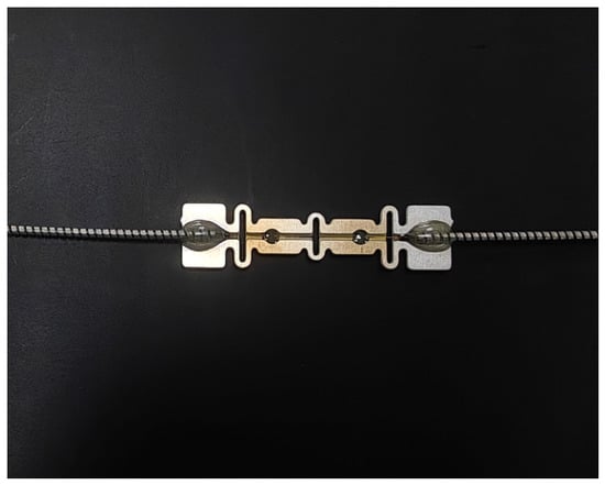
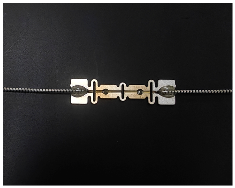
Figure 2 provides a photograph of the fabricated prototype of the proposed strain-desensitized FBG sensor.
Figure 2.
Photograph of the fabricated prototype of the proposed strain-desensitized FBG sensor.
A finite element analysis (FEA) was carried out in ANSYS Workbench 2020 R2 with the Static Structural solver. The interfaces between the bonding adhesive and the titanium-alloy coupon, as well as between the adhesive and sensor packaging structure, were set to fully bonded with no interfacial slip. Local mesh refinement with an element size of 0.05 mm was applied to the adhesive layer to avoid numerical errors caused by insufficient mesh layers across the contact interfaces. One end of the titanium-alloy plate was fixed, while axial loading was applied to the opposite end face to generate a global axial strain of approximately 6000 με. The quasi-static simulation adopted room-temperature, constant material properties for all components.
As shown in Figure 3, the FEA results were used to validate the structural design. Under an applied host global strain of 6000 με, the average strain of the FBG segment, computed from axial displacements at the two glass-brazed fixation points, reached 2398 με, yielding a simulated strain distribution coefficient of approximately 0.4. This good agreement verifies the effectiveness of geometric optimization and demonstrates the satisfactory strain transfer performance of the proposed sensor configuration.
Figure 3.
Axial deformation of FBG finite element analysis.
3. Results
3.1. Ground Calibration and Performance Characterization
3.1.1. Linearity and Sensitivity of Tensile Strain Across Full Temperature Range
To comprehensively evaluate the static strain measurement performance of the sensor over a wide temperature range, a full-range tensile calibration test was conducted on Sample No. 01, ranging from room temperature (~295 K) to liquid nitrogen (LN2) temperature (77 K). To avoid plastic deformation of the dog-bone specimen during the experiment, continuous testing on the same specimen was avoided; thus, the maximum tensile strain range was limited to 5128 με rather than the full scale. The test utilized a universal material testing machine combined with a high-precision extensometer, performing loading, unloading, and secondary repeated loading processes at five typical temperature points: room temperature, 223 K, 173 K, 123 K, and LN2 (77 K). Changes in the FBG sensor wavelength and actual strain values measured by the extensometer were recorded synchronously.
The Bragg wavelength of the FBG was monitored using a Micron Optics HYPERION si-155 FBG interrogation unit, which recorded the Bragg wavelength synchronously with the strain data acquired from the extensometer. The interrogation unit had a wavelength range of 1510–1590 nm and a wavelength resolution of 1 pm.
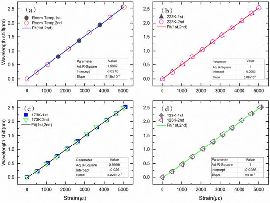
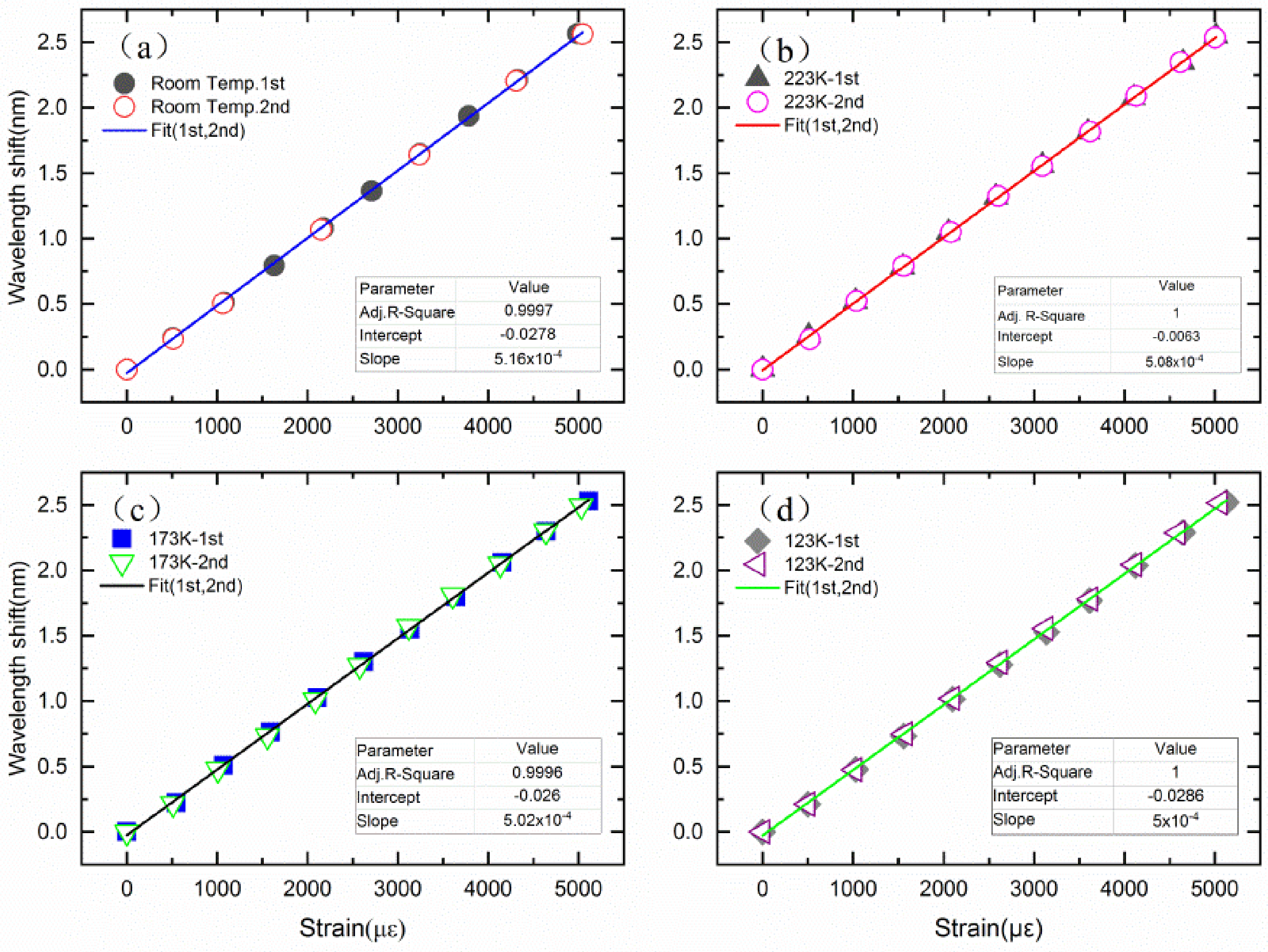
Figure 4 presents the tensile test data across the full temperature range. Two independent tensile tests were performed at each temperature point. The two loading curves at all tested temperatures exhibit close agreement with negligible hysteresis, indicating good repeatability and stability. Strong linearity was maintained between the sensor output wavelength and strain as the temperature decreased from room temperature to 123 K. The calculated strain sensitivities were 0.516 pm/με at room temperature, 0.508 pm/με at 223 K, 0.502 pm/με at 173 K, and 0.500 pm/με at 123 K. Before formal testing, a small pre-tensile load was applied, and the extensometer reading was reset to zero prior to data acquisition.
Figure 4.
Experimental data from two rounds of tensile tests and corresponding linear fitting curves at different temperatures. (a) Room temperature; (b) 223 K; (c) 173 K; (d) 123 K. The solid and hollow symbols represent the first and second cycle tensile test data, respectively, and the solid lines denote the linear fitting results.
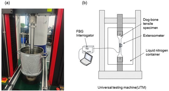
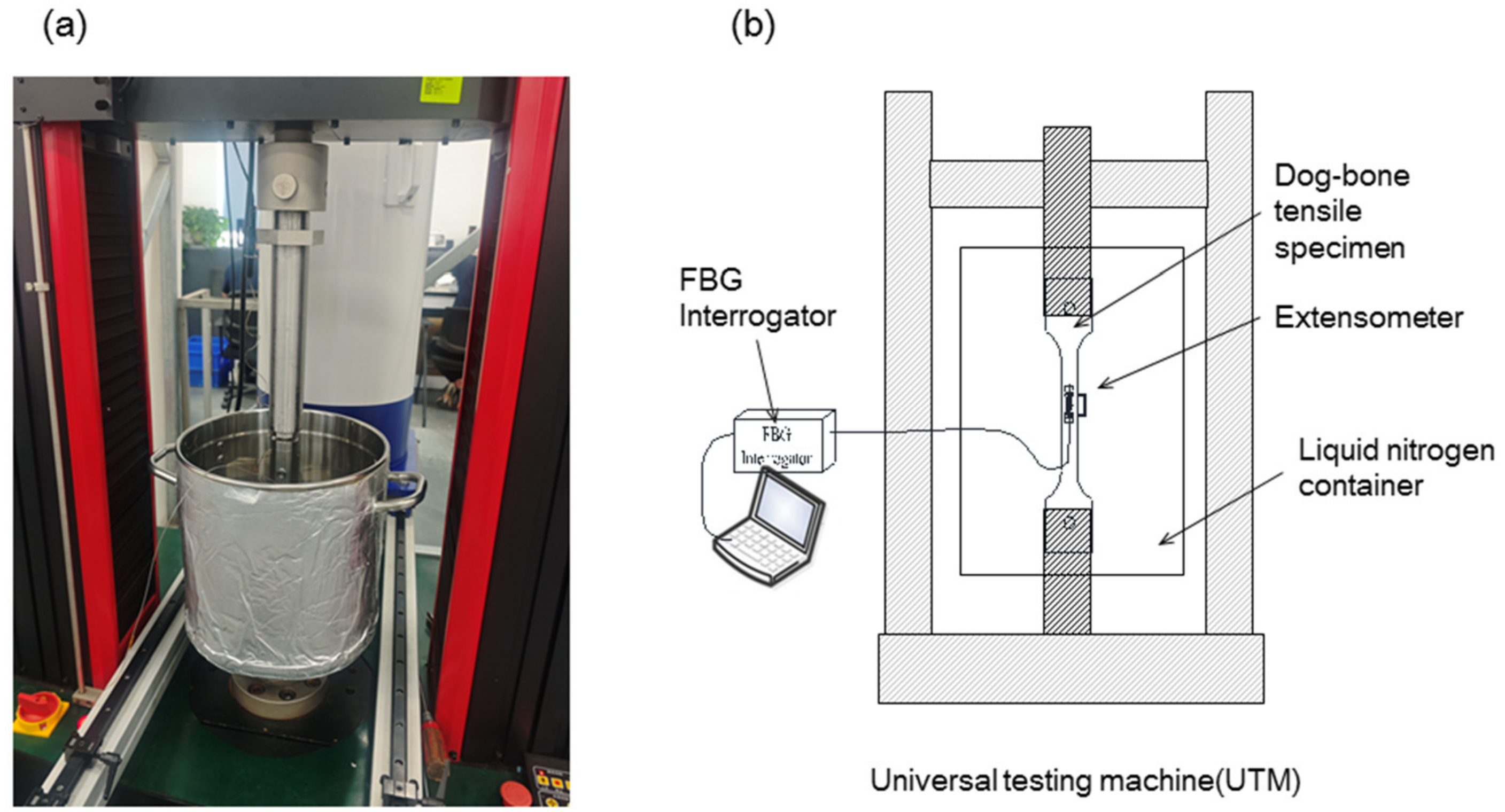
To further verify the reliability of the sensor in deep cryogenic environments, the universal testing machine was modified (as shown in Figure 5) to allow the loading mechanism to be fully immersed in liquid nitrogen. Two sets of tensile tests with ranges of 4000 με and 5632 με were performed.
Figure 5.
Liquid nitrogen environment test device. (a) photograph of the test facility; (b) schematic diagram of the test system.
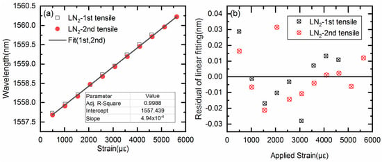
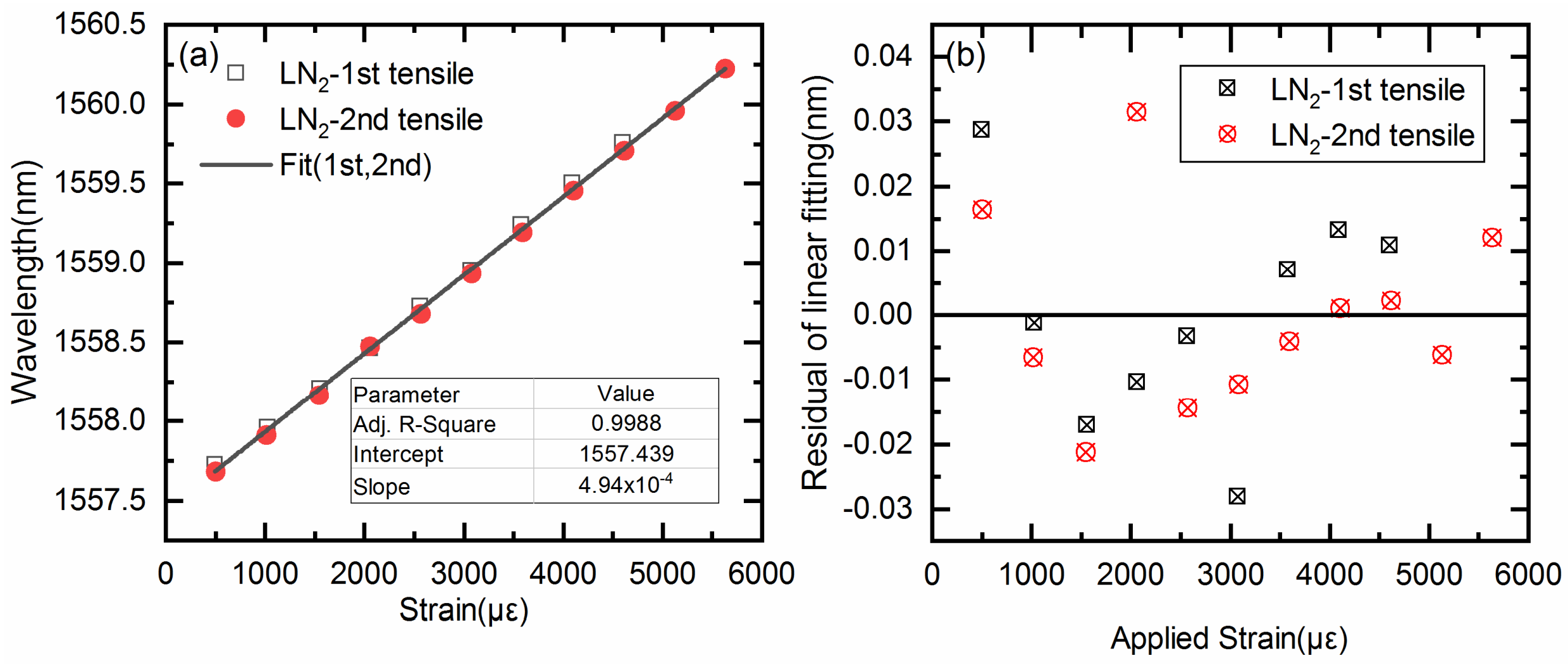
Figure 6 shows highly consistent data with no systematic deviation or obvious hysteresis. After least-squares fitting, the strain sensitivity under liquid nitrogen conditions was 0.494 pm/με, with an adjusted determination coefficient R2 = 0.99877. The residuals were uniformly and randomly distributed around the zero line, indicating that the sensor possesses extremely high measurement precision and linearity under deep cryogenic and large-strain conditions.
Figure 6.
Tensile strain test data in liquid nitrogen environment. (a) Wavelength–strain experimental points of two tensile cycles and their linear fit; (b) fitting residual plot against applied strain.
To quantify the impact of temperature on sensor performance, independent linear fittings were conducted on the tensile data at room temperature to LN2. The strain sensitivity and root mean square error (RMSE) were statistically analyzed, as summarized in Table 2.
Table 2.
Tensile strain sensitivity and RMSE of FBG sensors at different temperatures.
Table 2 reveals that the sensor maintained favorable linearity over the full temperature range, with full-scale errors all below 1%. The strain sensitivity decreased slightly with temperature, from 0.516 pm/με at room temperature to 0.494 pm/με at 77 K, corresponding to a variation of ~4.3%. This slight sensitivity–temperature drift supports the adoption of the full-temperature-range unified sensitivity calculation approach.
3.1.2. Compressive Strain Testing and Tension–Compression Asymmetry Analysis
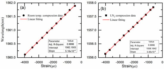
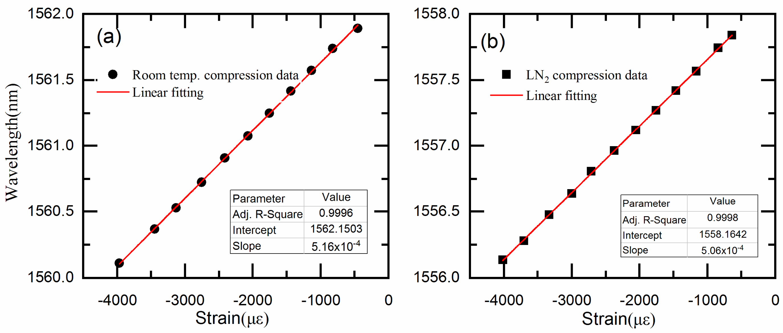
The sensor was mounted on a compression fixture, and compressive loading tests were conducted separately at room temperature and in liquid nitrogen, with loading ranges of −3969 με and 4018 με, respectively. The experimental results of these compressive tests are illustrated in Figure 7. At room temperature, the compression sensitivity was 0.516 pm/με, consistent with the tensile sensitivity, with an RMSE of 26.64 με and a full-scale error of 0.67% F.S. In liquid nitrogen, the compressive sensitivity was 0.506 pm/με, slightly higher than the tensile sensitivity in liquid nitrogen (0.494 pm/με), yielding a relative discrepancy of approximately 2.4%. Further calculations yielded an RMSE of 16.26 με and a full-scale error of 0.405% F.S.
Figure 7.
Compressive tests at room temperature and in liquid nitrogen. (a) Room-temperature compressive data with linear fitting; (b) liquid nitrogen compressive data with linear fitting.
Summarizing the tensile and compressive sensitivities of the FBG sensor at various temperature points in Table 3, it can be observed that the sensitivity decreased as the temperature dropped, with the decrease in the tensile strain sensitivity being greater than that of compressive strain. This is likely because the shear modulus of the installation adhesive increased and the toughness decreased at low temperatures. Under tension, micro-pores or defects inside the adhesive were more prone to expansion [22,23], which reduced the strain transfer efficiency. In contrast, microvoids and defects may have undergone compaction under compressive loading. Consequently, the attenuation of strain transfer efficiency under compression was less severe compared to the tensile tests, leading to the phenomenon of tension–compression asymmetry in low-temperature environments.
Table 3.
Summary of tensile and compressive sensitivities over full temperature range.
3.1.3. Validation of Batch Consistency and Inter-Unit Reproducibility
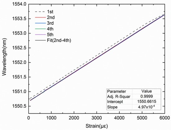
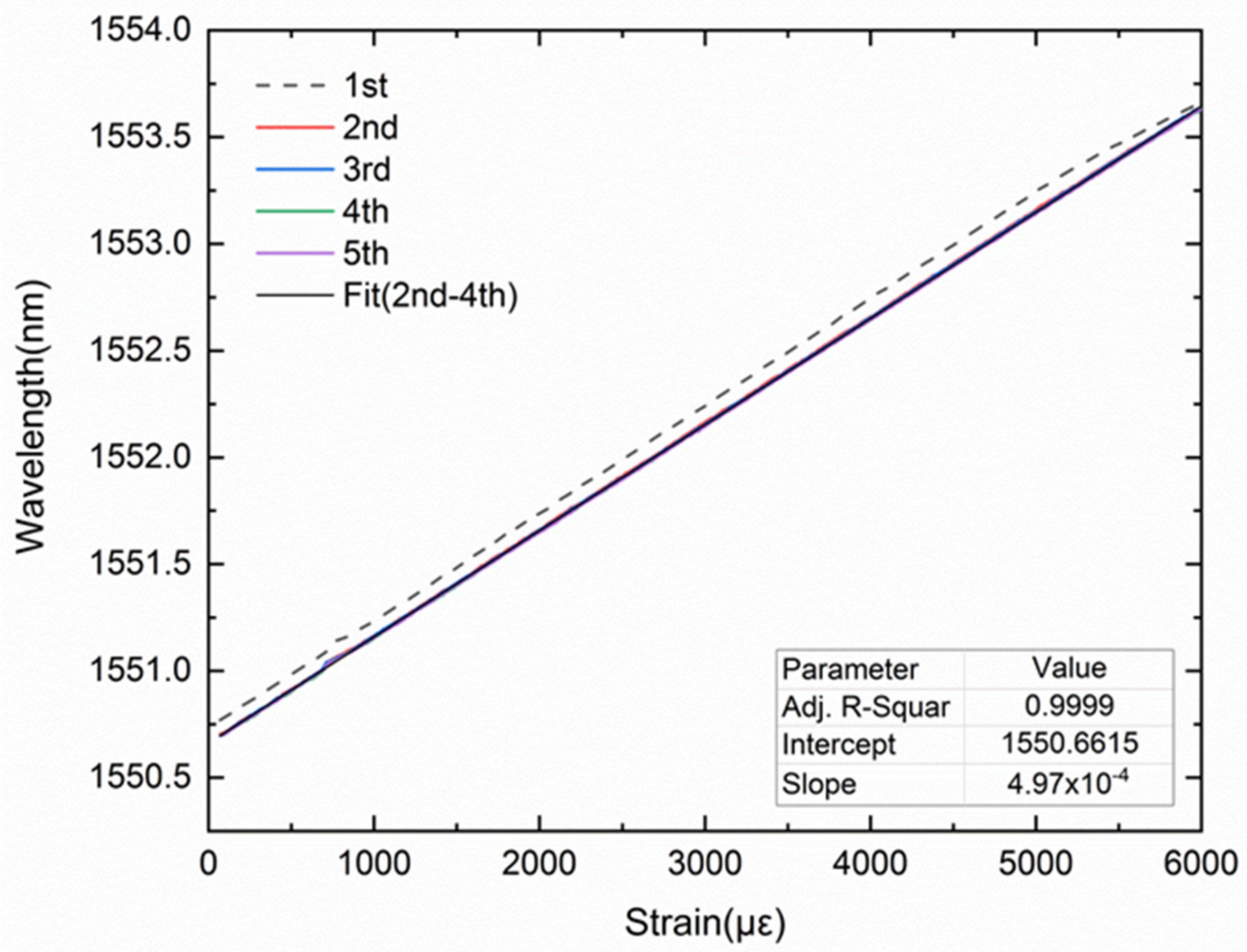
To rigorously evaluate the inter-unit consistency of the mass production process, a second unit (Sample 02) from the same production batch was subjected to identical characterization protocols. Sample 02 underwent five cyclic tensile tests at 123 K, with a maximum strain amplitude of 6000 με. As illustrated in Figure 8, the initial loading cycle exhibited a nonlinear deviation at approximately 5250 με. This transient artifact is attributed to localized plastic deformation of the external dog-bone specimen under peak load, rather than any intrinsic failure of the sensor itself. Despite this external disturbance, the FBG signal showed no permanent spectral distortion or drift. This shows that the graded-compliance metal packaging effectively protected the sensor from external overload.
Figure 8.
Data from five tensile tests of Sample 02 at 123 K.
Excluding this initial transient effect, the subsequent four cycles demonstrated high reproducibility with negligible hysteresis. A linear regression analysis of these stable cycles yielded a strain sensitivity of 0.497 pm/με (R2 = 0.99992) for Sample 02 at 123 K. When compared to the calibrated sensitivity of Sample 01 (0.500 pm/με) under identical conditions, the inter-unit deviation was only 0.6%. This minimal variance confirms the high repeatability of individual sensors. It also shows that the streamlined manufacturing process delivers consistent results across units.
3.2. Extreme Environment Reliability Verification
3.2.1. Rapid Thermal Cycling Test
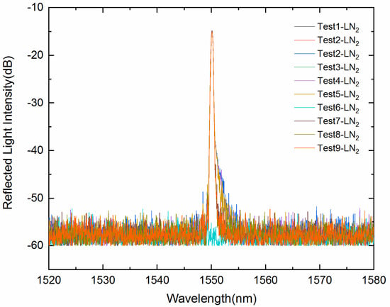
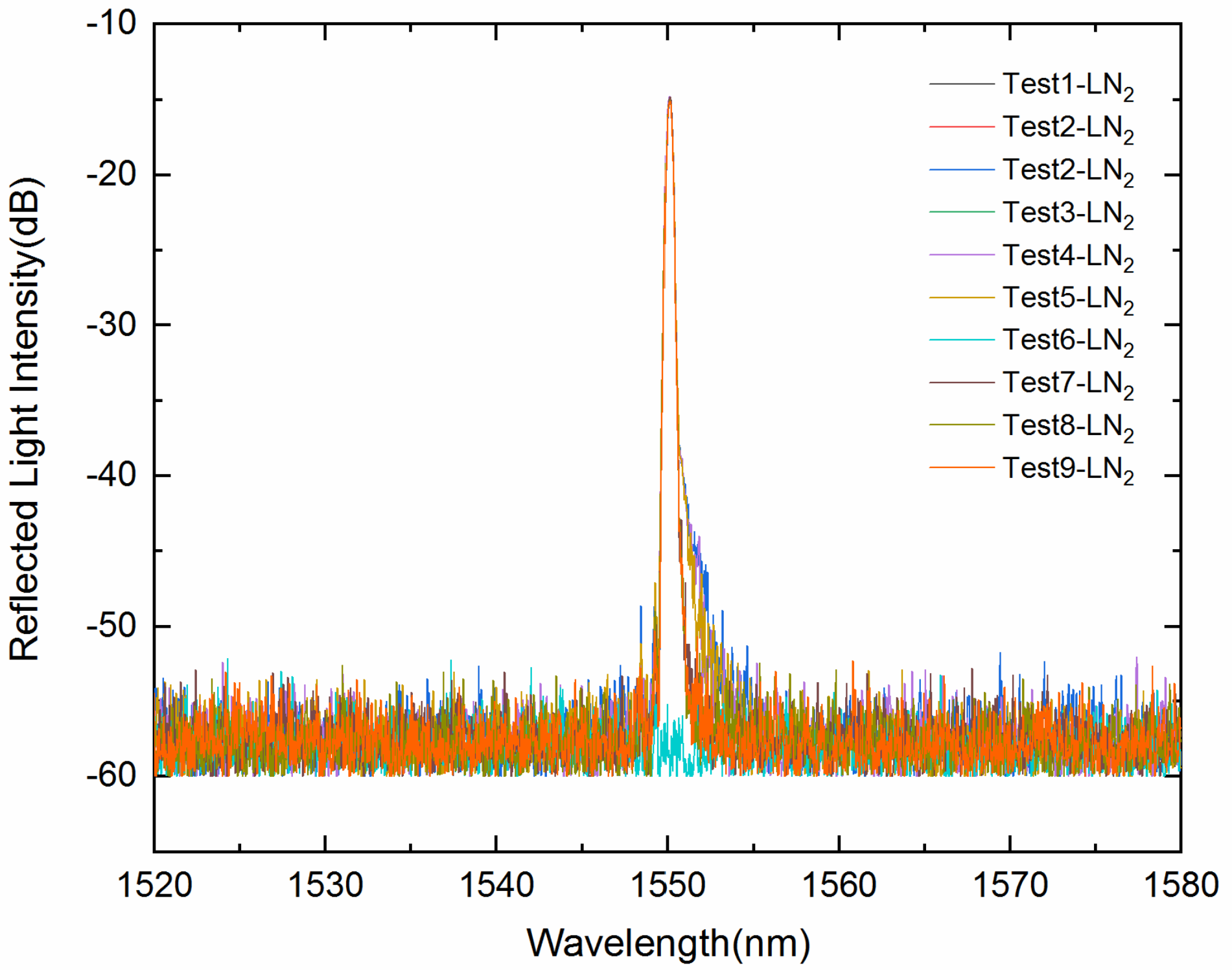
Sample No. 02 was subjected to nine rapid thermal cycling tests, involving direct immersion in liquid nitrogen for 5 min followed by passive recovery to room temperature, as well as a 72 h static soak in liquid nitrogen. As shown in Figure 9, the sensor’s reflection spectrum remained stable despite these drastic temperature fluctuations. Specifically, there was no broadening of the 3-dB bandwidth, nor were any spectral distortions—such as chirping or increased sidelobes—observed. These results validate the robustness of the metal packaging structure and glass brazing process under extreme cryogenic alternating environments.
Figure 9.
Spectra from 9 LN2 temperature–room temperature cycle tests.
3.2.2. Full-Scale Alternating Cycle Test
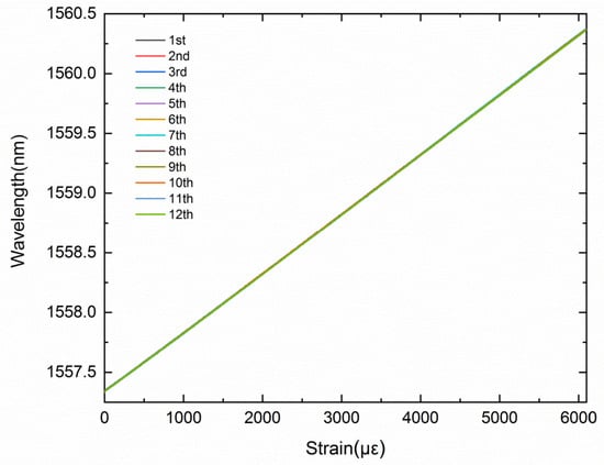
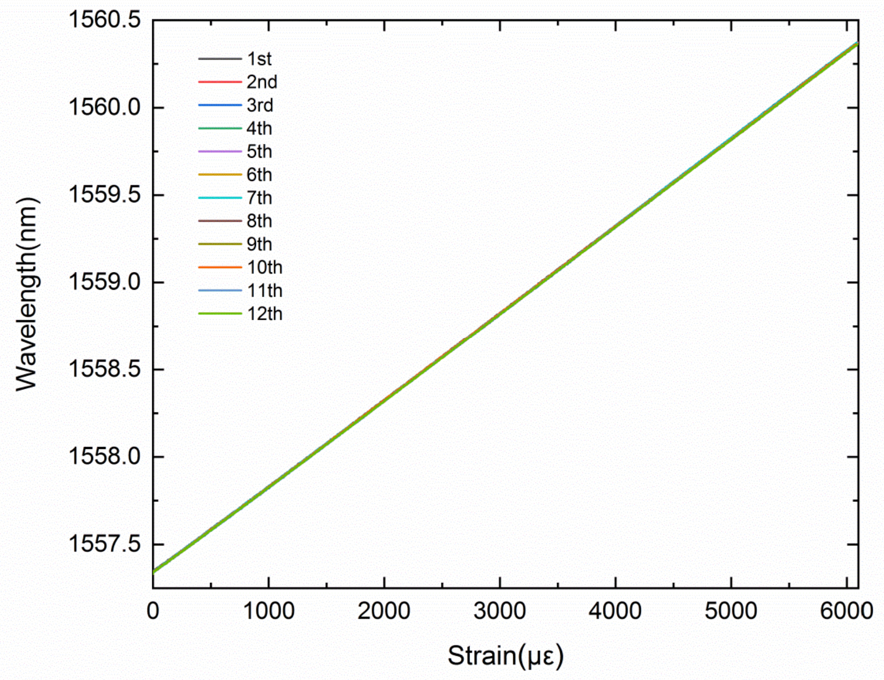
To assess the sensor’s adaptability to extreme cryogenic environments, a repeated loading test was performed on Sample 01, submerged in liquid nitrogen. The sensor endured twelve full-range tensile cycles with a maximum strain of 6130 με. As shown in Figure 10, the superimposed loading and unloading curves across all cycles exhibit excellent linearity and repeatability, with negligible hysteresis even at the strain limit. These results show that the sensor maintained stable performance even under severe cryogenic and high-strain conditions.
Figure 10.
Twelve tensile tests in liquide nitrogen.
3.3. Unified Sensitivity Calculation Approach
To mitigate the stringent constraints on the onboard telemetry bandwidth and reduce the computational burden on real-time avionics, a full-temperature-range unified sensitivity calculation approach is adopted and experimentally validated in this work. This processing method is supported by two experimental observations: limited drift of strain sensitivity within the target cryogenic operational window and the high inter-unit consistency achieved through streamlined manufacturing.
Given that the target application involves liquid oxygen/methane propulsion systems, which operate primarily within the 123 K to 77 K interval, the average strain sensitivity derived from these representative temperatures is adopted as the unified calibration parameter: Sunified = 0.497 pm/με. This unified parameter is applied to the wavelength output data across all temperature points for residual analysis and error statistics, as detailed in Table 4. The results indicate that within the target service interval (123 K to 77 K), the use of the unified sensitivity constrains the full-scale relative error to within 1.01%.
Table 4.
Statistical table of tensile and compressive strain errors under the unified sensitivity calculation approach.
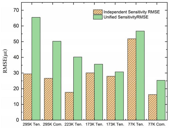
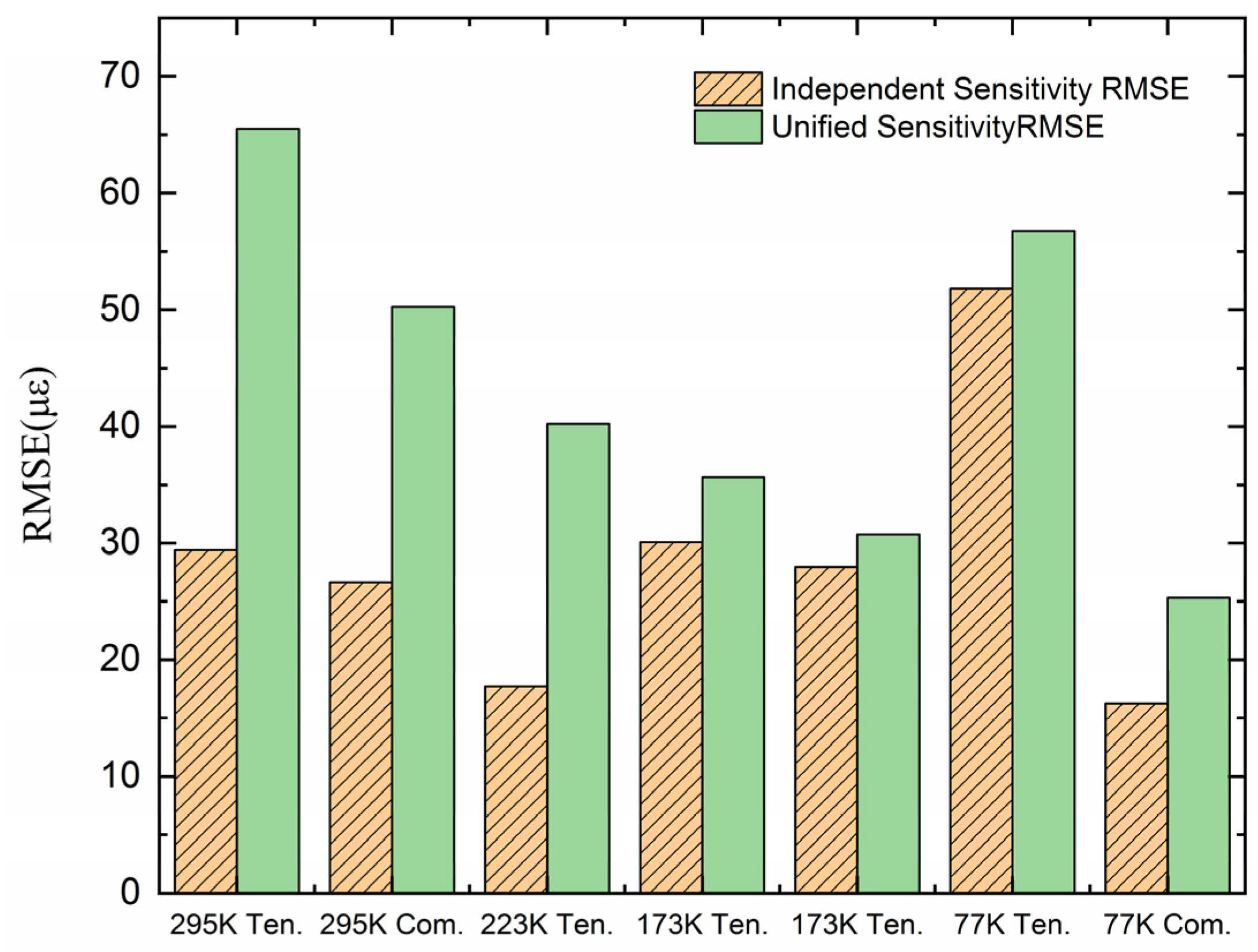
As illustrated in Figure 11, the strain root mean square error (RMSE) is compared before and after adopting the unified sensitivity calculation approach. Within the operational window, the maximum RMSE increment occurs at 77 K under compression, amounting to only 9.05 με. In contrast, the largest RMSE increment across the entire temperature range is observed at room temperature under tension, reaching 36.12 με. Although the error increments at room temperature and 223 K are more pronounced, these conditions lie outside the primary operational envelope for cryogenic applications. Therefore, the unified sensitivity calculation approach satisfies engineering precision requirements within the core operational window.
Figure 11.
Comparison of RMSE before and after adopting full-temperature-range unified sensitivity.
To further validate the engineering feasibility of applying a single unified parameter to batch-produced sensors, we refer to the analysis presented in Section 3.1.3. As previously demonstrated, the inter-unit sensitivity deviation between Sample 02 and Sample 01 is only 0.6% under identical conditions. This minimal discrepancy indicates that our manufacturing process produces consistently reliable results. More importantly, this shows that the unified sensitivity approach works not just for individual sensors but also for batch-produced units, so each sensor does not need to be recalibrated separately.
In summary, the unified sensitivity approach limits the intra-unit error to within 1.01% over the operating window and achieves an inter-unit consistency of 0.6%. This reduces data processing complexity while meeting the target engineering precision. The approach is suitable for large-scale deployment in reusable launch vehicles, where reducing the pre-launch calibration complexity and onboard computational load is important.
3.4. Flight Verification Test
Multiple batches of FBG strain sensors were manufactured, with batch sizes of 40 or 64 units. Flight-related environmental screening and acceptance tests were completed for these sensors before launch. Three flight campaigns were carried out aboard RLVs in 2024, 2025 and 2026, respectively.
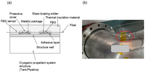
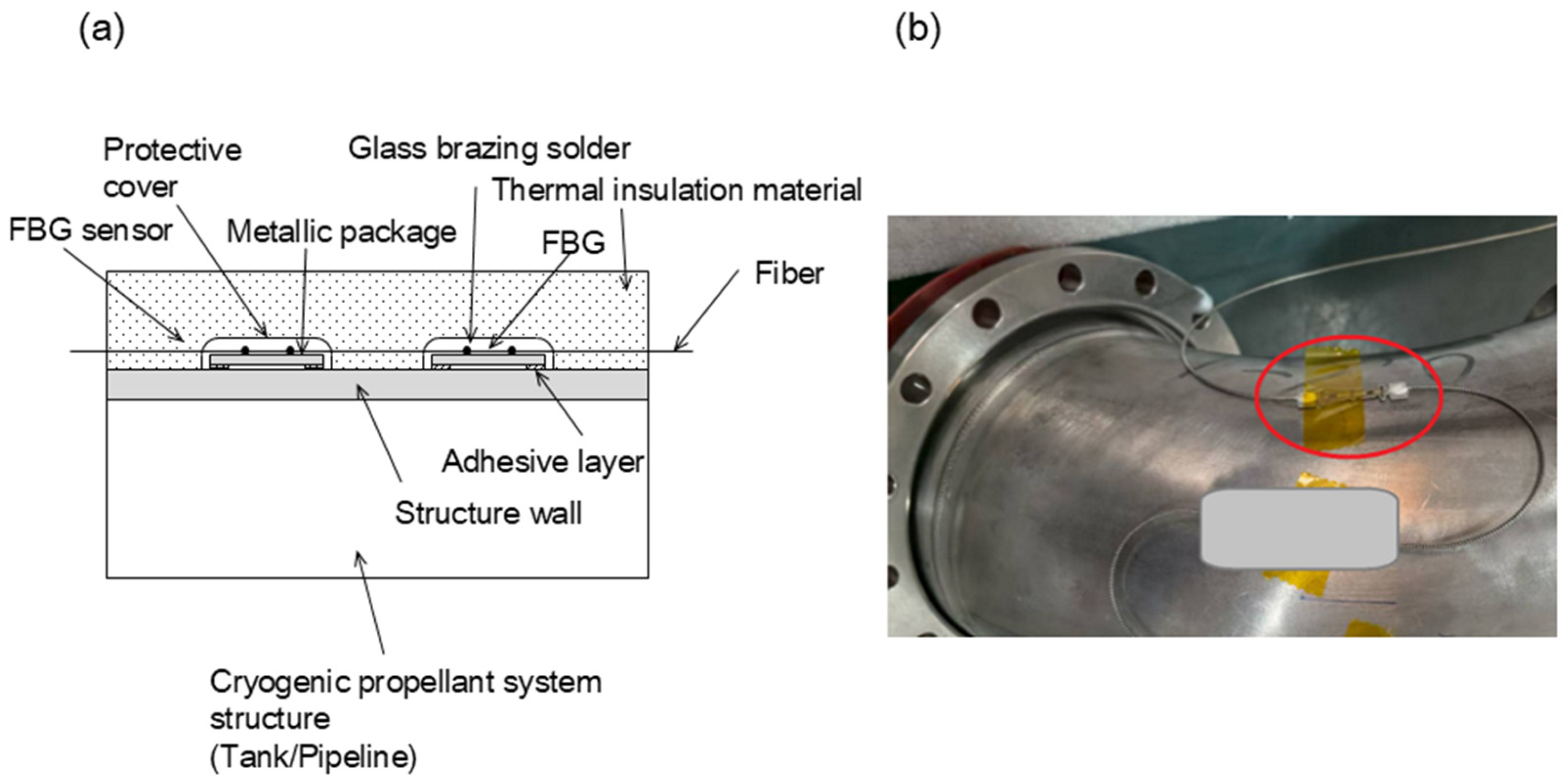
The metal-packaged FBG sensor was bonded onto the outer surface of the cryogenic pipeline. A mechanical protective cover was installed over the sensor. Thermal insulation material was then applied over the protective cover and the bare pipeline sections without sensors to provide uniform thermal protection. Figure 12 presents the flight-test sensor installation: (a) installation schematic; (b) on-site installation photograph taken during flight-test campaign.
Figure 12.
Flight-test sensor installation: (a) installation schematic; (b) on-site installation photograph taken during flight-test campaign.
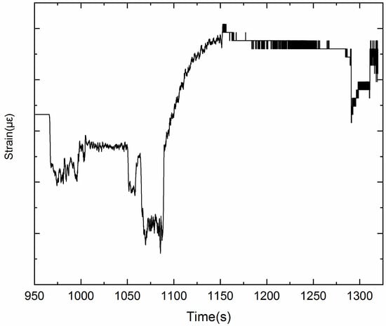
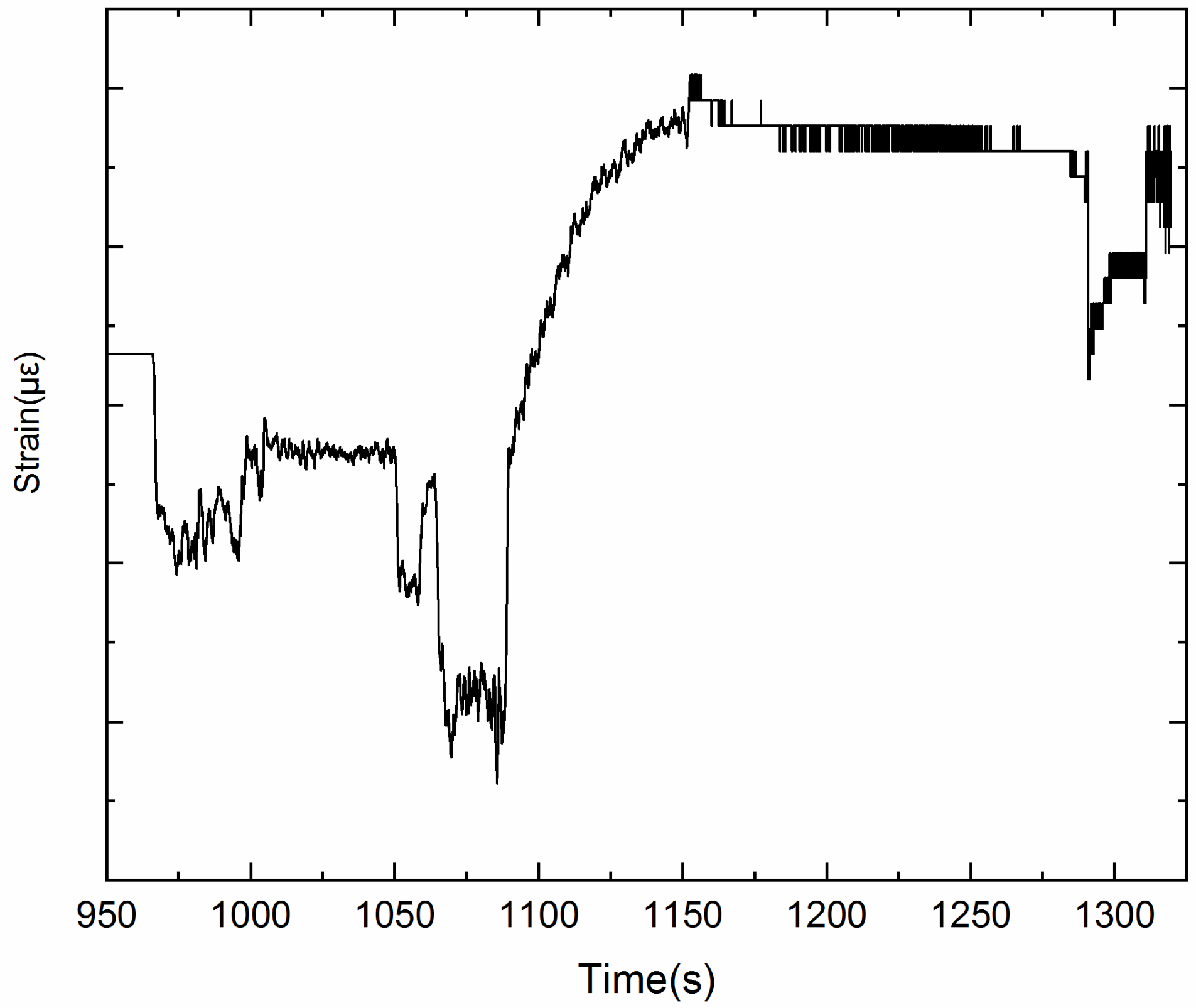
Sensors were deployed on key components, including cryogenic propellant delivery pipelines and landing buffer mechanisms. A representative flight strain history recorded on the cryogenic propellant pipeline is shown in Figure 12. For commercial secrecy restrictions, the vertical axis values are omitted to protect the customer’s flight vehicle status information.
The fiber-optic wavelength interrogation unit for flight measurement was developed by our team. It provides eight optical channels with a sampling rate of 125 Hz per channel. Its operating wavelength window covers 1510–1590 nm, matching the nominal 1550 nm center wavelength of the deployed FBG sensors, and features a wavelength measurement accuracy of 10 pm. This unit is qualified for launch vehicle service environments and is capable of enduring severe mechanical vibration and shock loads during launch–flight operations. Multi-sensor acquisition on each channel is implemented via wavelength-division multiplexing (WDM).
A segment of the flight time–history curve is presented in Figure 13. The measurement data were acquired throughout the whole procedure from ground propellant loading to in-flight operation. The sensors endured severe thermal shocks and mechanical vibrations during the missions, maintaining continuous and complete signal transmission without signal dropout or abnormal spikes. The measured strain values remained within expected ranges, with no abnormal drift, dropout, or step changes observed during flight. Together with the preceding ground calibration and reliability tests, the flight campaigns confirm the environmental adaptability and measurement performance of the graded-compliance metal-packaged FBG sensor under real aerospace conditions.
Figure 13.
Schematic diagram of strain in a certain cryogenic propellant delivery pipeline.
4. Discussion and Conclusions
This study develops a graded-compliance metal-packaged FBG strain sensor for structural health monitoring of metallic cryogenic tanks and pipelines on reusable launch vehicles. The sensor combines a graded-compliance structural design with glass-brazed, adhesive-free fixation of the optical grating to address the harsh conditions inside cryogenic propellant systems.
The design decouples the FBG from external mounting-related loads via a graded-compliance metal frame, improving the long-term strain-measurement stability. Minor bonding defects or microcracks in the outer adhesive layer do not disable the sensor. Multi-stage flexible-frame deformation reduces the interfacial shear stress, lowering risks of crack propagation and debonding induced by thermal expansion coefficient mismatch under repeated thermal cycling. Its low-stiffness profile preserves the native stress state of the monitored component. The glass-brazed joints without organic adhesive inside the package secure reliable strain transfer over long-duration cryogenic operation.
The all-metal packaging enables standardized fabrication and batch calibration. The sensors produced in batches show consistent geometry and mechanical properties. Calibration runs at 123 K and at liquid nitrogen temperature (77 K) support a unified sensitivity calculation approach for the primary cryogenic operating window. Individual temperature-dependent calibration for every sensor becomes unnecessary, which reduces the ground test effort for large-scale deployment. This approach removes real-time temperature compensation and extra demodulation calculations, suiting the tight computational budgets of onboard avionics systems. From 77 K to 123 K, the maximum full-scale error stays within ±1.01%. Outside this range, the error rises to 1.3%, which remains acceptable for routine structural monitoring.
The strain desensitization from the custom flexible-frame geometry lets the sensor accommodate the large strains seen on cryogenic tank structures.
The frame dimensions may be modified during design to tune the sensor sensitivity for different measurement requirements.
The valid measurement range extends from −4000 με to 6000 με, with linearity maintained at (R2 > 0.998) across all tests. The tensile sensitivity shifts from 0.516 pm/με to 0.494 pm/με between room temperature and 77 K, a total variation of 4.3%. The tension–compression sensitivity matches closely at room temperature. Small low-temperature asymmetry arises from mechanical changes within the mounting adhesive. Units from the same production batch show only a 0.6% sensitivity deviation at 123 K, confirming good intra-batch consistency.
The thermal cycling and high-strain cyclic loading tests confirm that the sensor sur-vives extreme temperature swings and alternating mechanical loads without spectral distortion or baseline drift. Sensors from multiple batches have passed environmental qualification and flown on three reusable launch vehicle missions. Continuous strain records were captured from ground-based propellant filling through the complete flight profile. The measured strain values agree well with the structural predictions.
The graded-compliance metal-packaged design mitigates adhesive-related failure risks for fiber-optic sensing. It delivers wide-range strain measurement and simplifies onboard data processing. The unified sensitivity calculation approach allows laboratory calibration data to be used directly for in-flight data processing, eliminating the need for re-calibration between ground testing and deployment. Recorded strain histories can help quantify the cumulative structural damage over repeated missions, a critical requirement for the safe reuse of liquid-propellant launch vehicle components.
5. Patents
A patent application related to the research content has been filed and is currently pending. The applicant played no role in the study design, manuscript preparation, or publication decisions.
Author Contributions
Conceptualization, Writing—original draft, Methodology, Data curation, Validation—Z.S.; Software, Data curation—J.N.; Validation, Investigation—Y.Y. (Yu Yang), H.N., and Y.Y. (Yan Yang); Data curation, Resources—T.L. and K.G.; Writing—review and editing, Project administration—Z.W.; Supervision, Writing—review and editing—Y.P. All authors have read and agreed to the published version of the manuscript.
Funding
This research received no external funding.
Data Availability Statement
The original contributions presented in this study are included in the article. The raw flight-test data are restricted due to commercial confidentiality requirements and are not publicly available.
Conflicts of Interest
One patent application related to this work has been submitted for filing. Authors Tao Liu and Kaixiang Gong are employed by China Aerospace Science and Technology Commercial Launch Vehicle Group Co., the client for this flight test. Their employer did not fund product development and holds no rights to the related pending patent. This affiliation did not affect the study’s design, data, or conclusions. The authors declare no other conflicts of interest.
References
- Stephen, J.; Pal, P.; Mathew, J. Advances in cryogenic temperature sensing using fiber Bragg grating. IEEE Sens. J. 2025, 25, 23514–23525. [Google Scholar] [CrossRef] [Scilit]
- Prosser, W.H.; Brown, T.L.; Woodard, S.E.; Fleming, G.A.; Cooper, E.G. Sensor technology for integrated vehicle health management of aerospace vehicles. In Proceedings of 29th Review of Progress in Quantitative Nondestructive Evaluation, Bellingham, WA, USA, 14–19 July 2002. [Google Scholar] [CrossRef] [Scilit]
- Kang, H.K.; Park, J.S.; Kang, D.H. Strain monitoring of a filament-wound composite tank using fiber Bragg grating sensors. Smart Mater. Struct. 2002, 11, 848–853. [Google Scholar] [CrossRef] [Scilit]
- Nobuo, T.; Tadahito, M.; Kentaro, H.; Yoji, O. Application of fiber Bragg grating sensors to real-time strain measurement of cryogenic tanks. In Proceedings of the SPIE Smart Structural and Integrated Systems; SPIE: Bellingham, WA, USA, 2003; Volume 5056, pp. 304–311. [Google Scholar] [CrossRef] [Scilit]
- Frövel, M.; Pintado, J.M.; Güemes, A.; del Olmo, E.; Obst, A. Multiplexable fiber Bragg grating temperature sensors embedded in CFRP structures for cryogenic applications. In Proceeding of the 3rd European Workshop Structure Health Monitoring, Granada, Spain, 5–7 July 2006. [Google Scholar]
- Ludbrook, B.M.; Fernandez, F.S.; Ramesh, M.; Phoenix, B.; Moseley, D.A.; Schuyt, J.J.; Fernando, G.; Badcock, R.A. Resilience of fiber-Bragg grating optical sensors under neutron irradiation at 77 K. IEEE Trans. Appl. Supercond. 2025, 35, 9000105. [Google Scholar] [CrossRef] [Scilit]
- Huang, G.J.; Shao, J.Y.; Wang, Q.L.; Deng, P.F.; Dai, F.; Feng, Z.A. Strain sensing characteristics of fiber Bragg gratings at liquid nitrogen temperature. Optoelectron. Laser 2007, 18, 773–775. [Google Scholar] [CrossRef]
- Li, S.D.; He, W.; Li, Z.H. Mechanical characteristic analysis of special hybrid adhesive-packaged FBG strain sensor at liquid helium environment. IEEE Sens. J. 2024, 24, 8212–8220. [Google Scholar] [CrossRef] [Scilit]
- Yang, C.Q.; Wen, F.; Zhou, Z.; Yang, N.; Yao, Y.; Li, S. Experimental study on the double-head tube packaging fiber Bragg grating at cryogenic temperature. Opt. Instrum. 2022, 44, 37–42. [Google Scholar] [CrossRef]
- Allison, S.G.; Prosser, W.H.; Hare, D.A.; Moore, T.C.; Kenner, W.S. Optical fiber distributed sensing structural health monitoring (SHM) strain measurements taken during cryotank Y-joint test article load cycling at liquid helium temperature. In NASA Technical Memorandum:NASA/TM-2013-217345; NASA Langley Research Center: Hampton, VA, USA, 2013. [Google Scholar]
- González del Val, M.; Martínez Olmo, J.M.; Salazar Castamán, Á.S.; Cabrerizo, F.; Frovel, M. Monitoring microcracking and leakage of a hydrogen tank using fiber optics and the thermal expansion. J. Compos. Sci. 2026, 10, 21. [Google Scholar] [CrossRef] [Scilit]
- Zhang, X.; Chen, G.; Jiang, J.; Fan, X.; Liu, K.; Wang, S.; Liu, Y.; Ni, J.; Liu, T. Weak fiber Bragg grating based sensing system for cryogenic static test of launch vehicle oxygen tank. Laser Optoelectron. Prog. 2021, 58, 2136001. [Google Scholar]
- Zhu, C.J.; Liu, Y.T.; Liu, Y.; Ying, X.; Xiao, C.C. Research on the application of FBG in online monitoring of common bulkhead structure for rocket cryogenic tanks. Chi. J. Sci. Instru. 2025, 46, 1–9. [Google Scholar] [CrossRef]
- Hill, K.O.; Meltz, G. Fiber bragg grating technology fundamentals and overview. J. Light. Technol. 1997, 15, 1263–1276. [Google Scholar] [CrossRef] [Scilit]
- Xu, M.G.; Archambault, J.L.; Reekie, L.; Dakin, J.P. Discrimination between strain and temperature effects using dual-wavelength fibre grating sensors. Electron. Lett. 1994, 30, 1085–1087. [Google Scholar] [CrossRef] [Scilit]
- Song, M.; Lee, S.B.; Choi, S.; Lee, B. Simultaneous measurement of temperature and strain using two fiber Bragg gratings embedded in a glass tube. Opt. Fiber Technol. 1997, 3, 194–196. [Google Scholar] [CrossRef] [Scilit]
- Zhou, R.; Yu, J.; Dai, Y.; Tang, J.; Yang, M.; Mumtaz, F. Multiparameter optimization and adaptive temperature compensation for FBG strain sensors in wide-temperature-range aerospace applications. IEEE Sens. J. 2026, 26, 8196–8205. [Google Scholar] [CrossRef] [Scilit]
- Huang, X.; Davies, M.; Moseley, D.; Salazar, E.; Sanabria, C.; Duke, O.; Ludbrook, B.; Badcock, R. Temperature and strain sensitivities of a groove-bonded fiber Bragg grating at room and cryogenic temperatures. Appl. Opt. 2022, 61, 8427–8434. [Google Scholar] [CrossRef] [Scilit]
- Floris, F.; Sangiorgio, V.; Adam, J.M.; De Roeck, G. Effects of bonding on the performance of optical fiber strain sensors. Struct. Control Health Monit. 2021, 28, e2634. [Google Scholar] [CrossRef] [Scilit]
- Ansari, F.; Yuan, L. Mechanics of bond and interface shear transfer in optical fiber sensors. J. Eng. Mech. 1998, 124, 385–394. [Google Scholar] [CrossRef] [Scilit]
- Li, B.; Liu, W.; Cao, D. Effect of typical adhesives on strain transfer fiber grating sensors in variable temperature environments. Equip. Environ. Eng. 2023, 20, 90–96. [Google Scholar]
- Wang, H.P.; Ni, Y.Q.; Dai, J.G.; Yuan, M.D. Interfacial debonding detection of strengthened steel structures by using smart CFRP-FBG composites. Smart Mater. Struct. 2019, 28, 115001. [Google Scholar] [CrossRef] [Scilit]
- Liu, Y.; Yang, G.; Xiao, H.M.; Feng, Q.P. Mechanical properties of cryogenic epoxy adhesives: Effects of mixed curing agent content. Int. J. Adhes. Adhes. 2013, 41, 113–118. [Google Scholar] [CrossRef] [Scilit]



Disclaimer/Publisher’s Note: The statements, opinions and data contained in all publications are solely those of the individual author(s) and contributor(s) and not of MDPI and/or the editor(s). MDPI and/or the editor(s) disclaim responsibility for any injury to people or property resulting from any ideas, methods, instructions or products referred to in the content. |
© 2026 by the authors. Licensee MDPI, Basel, Switzerland. This article is an open access article distributed under the terms and conditions of the Creative Commons Attribution (CC BY) license.