


Abstract
Underground mine inspection is a critical operation for safety and resource management. It presents unique challenges, including confined spaces, harsh environments, and the lack of reliable positioning systems. This paper presents the design, development, and evaluation of an Unmanned Aerial Vehicle (UAV) specifically engineered for supervised autonomous inspection in subterranean scenarios. Key technical contributions include mechanical adaptations for collision tolerance, an optimized sensor-actuator selection for navigation, and the deployment of a mission-governing state machine for seamless autonomous acquisition. Furthermore, we detail the data treatment workflow, employing a multi-modal point cloud registration technique that successfully integrates high-resolution visual-depth scans of critical mine pillars into a comprehensive, globally referenced map derived from Light Detection and Ranging (LiDAR) data of the entire workspace. We show experiments that illustrate and validate our approach in two real-world scenarios, a simulated coal mine used to train mine rescue teams and an operating Limestone mine.
1. Introduction
Advances in commercially available drone technology, lower costs of electronic components, and expanded research in Unmanned Aerial Vehicles (UAVs) have opened opportunities to deploy these vehicles in the most unexpected territories. One of the most valuable fields in which UAVs have been deployed is inspection across many sectors, including buildings [1,2], infrastructure [3,4], agriculture [5], and mining [6,7]. The mining industry has increasingly adopted UAVs for both surface and underground inspections, as detailed in the comprehensive review by Shahmoradi et al. [6]. The proliferation of user-friendly and affordable multi-rotor platforms over the last decade has accelerated this trend [8,9]. However, significant hurdles remain, as was highlighted by a recent survey [10], which emphasizes the persistent challenges in Global Navigation Satellite System (GNSS)-denied environments and identifies critical needs for enhanced autonomy, advanced sensor integration, and better interoperability within mining infrastructure.
Besides the lack of GNSS signals, there are numerous challenges when deploying multi-rotor drones in an underground mine, including a limited range of radio-based teleoperation and harsh conditions such as humidity, dust, and, more importantly, darkness. Modern algorithms and the increasing use of cameras are driving the widespread adoption of Visual Inertial Odometry (VIO) across many GNSS-denied environments [11]. In illuminated mines, pure VIO can be highly reliable. However, a significant challenge arises when inspecting mine sectors where lighting is not maintained, rendering this approach insufficient. In such cases, additional sensor technology and different algorithms are required. One of the most effective solutions in these situations is the use of Light Detection and Ranging (LiDAR) sensors, along with corresponding LiDAR Inertial Odometry (LIO) algorithms. A few commercial drone models use this approach, including the Skydio X10 [12], which uses infrared lights to navigate in the dark, and the ElioS 3 [13], which features a hybrid LiDAR and camera system.
Current platforms lack real-world validation data demonstrating their capacity to maintain localization and mapping integrity under severe noise, heavy dust, and illumination variance characteristics of active mining sites. While recent initiatives have begun to address these issues [14], the technical literature demonstrating integrated UAV mapping systems that operate consistently in uncontrolled environments is scarce. Much of the research is limited to validation in controlled environments, rather than the dynamic, harsh conditions of active industrial mines [15]. This gap in the literature is often exacerbated by the current market. While commercial drones capable of subterranean mapping exist, their high cost and closed architectures often limit their accessibility and adaptability for specific research or industrial needs. This work focuses on a hands-on experimental approach, fusing established hardware and software into a modular, cost-effective platform specifically tailored for underground mine inspection. Rather than proposing entirely new algorithms, our contribution lies in the integration and real-world validation of a system that can reliably perform autonomous missions in GNSS-denied, unlit, and dusty environments. By providing a detailed account of the hardware trade-offs and the multi-modal data fusion process, this research demonstrates a practical methodology for achieving engineering-grade 3D reconstructions using an open-architecture system.
2. Related Work
The deployment of autonomous robotic systems in subterranean environments presents a unique intersection of challenges involving robust mechanical design, resilient onboard real-time state estimation, and high-fidelity data acquisition, as well as inherent deployment challenges that can significantly affect their effectiveness. These challenges include limited flight time and the need for onboard computers to process data and execute flight control algorithms, which must be lightweight yet sufficiently capable of handling complex computational demands, often involving trade-offs between overall performance and payload capacity [14]. Additionally, integrating various sensors such as high-resolution cameras, LiDAR, and thermal imaging devices adds complexity, weight, and size, further reducing flight time while enhancing the vehicle’s operational capabilities.
To contextualize this work’s contributions, it is worth noting that this is part of a broader mine safety research project and is related to the work presented in [16,17,18]. Given the multidisciplinary nature of the research, it is relevant to explore the existing literature across three foundational domains: UAV mine inspection, navigation in GNSS-denied environments, and 3D reconstruction techniques.
2.1. UAV Mine Inspection
The mining industry, like most industries in modern society, is currently undergoing a transformation characterized by the integration of computational systems to remove human operators from hazardous environments [19]. Traditionally, underground inspection requirements for geotechnical assessments, monitoring, and analysis have been done manually, exposing surveyors to risks such as rockfalls, toxic gas accumulation, and heavy machinery traffic. One of the most advanced technologies in recent years has been the Simultaneous Localization and Mapping (SLAM)-enabled handheld scanners [20,21].
Early efforts in the field of robotic mine inspection focus on Unmanned Ground Vehicles (UGVs). One of the primary works was done by Thrun et al. [22], which presents a mobile robot that builds maps of abandoned mines. While UGVs offer significant advantages in payload capacity and battery life, their utility in active mining zones is often constrained by the terrain, which limits their ability to inspect difficult-to-access areas. More recent advances have shown the utility of heterogeneous robot teams for exploring mines. The winning team of the DARPA Subterranean Challenge in 2021 demonstrated the individual advantages of UGVs and UAVs, as well as the use of different payloads depending on the task [15]. Thus, recent literature has shifted focus toward UAVs, which can provide the necessary agility to bypass ground obstacles and access vertical structures. However, aerial platforms impose significant constraints on flight time and payload capacity. Unlike ground vehicles, multi-rotor UAVs must continuously expend energy to overcome gravity, necessitating highly efficient hardware and software [23]. To address these limitations, a leading strategy is to deploy heterogeneous teams that combine the endurance of UGVs with the agility of UAVs [16,24].
When operating a UAV underground, it is important to distinguish between the three applications discussed in the literature, as they dictate different architectures and algorithms:
- Navigation: is the safe transit of a robot from a start pose to a goal pose. In underground settings, this is complicated by the symmetric design of mines, narrow corridors, and a harsh environment. Recent work has focused on topological graph-based navigation to efficiently move through tunnel networks without requiring dense maps [25].
- Exploration: refers to the autonomous navigation of completely unknown environments. Exploration algorithms often use Frontier-Based strategies, in which the robot prioritizes moving to the boundary between known and unknown space. While effective for autonomous navigation and search-and-rescue tasks, these strategies often yield sparse, incomplete, or textureless maps that are inadequate for structural engineering assessments [18,26,27].
- Inspection: differs from exploration by assuming that the general structure or a specific region of interest (ROI) has been identified, and that the robot’s goal is to gather high-fidelity data on that target [16]. Inspection is the main focus of this paper.
For inspection tasks, UAVs are typically equipped with a combination of LiDAR sensors and depth cameras to ensure robust navigation and data capture. LiDAR-based UAVs are shown to be more robust and reliable, but have a higher cost and weight. Depth cameras are limited to short distances and are much more sensitive to lighting conditions. Therefore, more complex approaches use multiple sensors and integrate them, at the cost of high power consumption and increased weight, which affect the vehicle’s overall size. Deploying UAVs underground requires hardware architectures that can survive harsh conditions, such as dark, humid, and/or dusty environments. Commercial solutions like the Flyability Elios 3 [13] use collision-tolerant cages to protect the drone, with the trade-off in the aerodynamic and weight. On the academic side, research platforms prioritize modularity to adapt to different constraints. For example, the Prometheus system [14] uses a reconfigurable frame for narrow passages, and the Oxpecker [16] uses a tether to bypass battery limits. The main hardware challenge across all these designs is balancing heavy sensors—like 3D LiDARs and high-power lights—with the weight and power limits of a multi-rotor drone. This trade-off directly dictates flight time and mission achievements.
The mission control architecture is as important as the hardware. Subterranean flights need robust stacks to handle communications, reactive collision avoidance, and autonomous navigation. High-end commercial platforms like ExynAero [28] and Hovermap [29] use proprietary software for continuous mapping. On the other hand, academic solutions often use Finite-State Machines (FSM) or behavior trees to manage different flight phases and sensor inputs [7,15]. To put these different hardware, autonomy, and localization approaches into perspective, Table 1 provides a representative comparison of recent commercial and academic underground platforms.
Table 1.
Comparison of Recent Underground UAV Solutions.
2.2. Navigation in GNSS-Denied Environments
Reliable localization is the fundamental condition for robotics. Outdoors, GNSS provides absolute positioning with bounded error. However, underground mining environments are GNSS-denied, forcing robotic platforms to rely entirely on onboard sensors to estimate their state (position, velocity, and attitude) relative to a local reference frame. This process, known as dead reckoning, accumulates error over time (drift), necessitating sophisticated sensor fusion strategies to bound this uncertainty [30]. Some relevant approaches are VIO, LIO, and SLAM.
Visual Inertial Odometry fuses high-frequency inertial measurements from an Inertial Measurement Unit (IMU) with visual features extracted from camera images. The IMU provides accurate short-term motion estimation, while visual features such as corners, edges, or distinctive texture patches are tracked across frames to correct the inertial drift. Some state-of-the-art algorithms used for SLAM and VIO are Kimera2 [31], Fast ORB-SLAM [32], VINS-Mono [33], ROVIO [34], and OpenVINS (Version 2.7) [35]. These tightly-coupled frameworks combine camera and IMU states into a single nonlinear optimization graph or filter, enabling robust estimation even during aggressive maneuvers. VIO is convenient when features are present in the context. However, the application of VIO in underground mines faces critical limitations, including a lack of distinct features and airborne dust, which can lead to catastrophic divergence of the estimator. This problem, in a more general context, is called navigation in degraded environments [36].
To overcome the dependence on ambient light and surface texture, active sensing methods have become a standard for harsh industrial environments. LiDAR sensors emit laser pulses to measure distance, making them independent of direct light sources. One of the initial research studies presented by Zhang and Singh [37] demonstrated that geometric features could be used to register sequential scans and estimate motion. This approach has evolved into tightly coupled smoothing frameworks such as LIO-SAM [38], which integrate IMUs to handle the rapid dynamics of UAV flight. Most recently, FAST-LIO 2.0 (2021-07-05 Update) [39] marked a significant advancement by using an incremental kd-tree (ikd-tree) data structure and allowing direct registration of raw points to the map without explicit feature extraction, reducing computational load and increasing robustness in unstructured environments. In mining applications, where dust can degrade visual data, the geometric consistency provided by LIO is often superior to that of visual methods.
It is important to distinguish between pure odometry (VIO/LIO) and SLAM. Odometry focuses on local consistency, estimating motion from one step to the next. SLAM adds information to build a map concurrently. Most recent research has added loop-closure capabilities to recognize previously visited locations and correct accumulated drift across the entire trajectory. While SLAM provides global map consistency, it is computationally more expensive than pure odometry [39,40,41].
2.3. Reconstruction Techniques
Underground 3D reconstruction techniques can be grouped into three primary categories: image-based photogrammetry, visual SLAM, LiDAR SLAM, and hybrid approaches that combine elements of these methods. Depending on the mission requirements, each category offers different trade-offs between reconstruction fidelity, robustness to environmental conditions, and suitability for real-time autonomous operation in GNSS-denied subterranean environments. These approaches have been applied in UAV-based underground inspection and mine mapping systems that employ LiDAR-based and hybrid SLAM pipelines for autonomous 3D reconstruction [16,42,43].
Photogrammetry is the process of obtaining accurate measurements from images to produce 3D models or maps. Structure from motion (SfM) is an evolved photogrammetric method for generating high-fidelity 3D reconstructions [44]. With multi-view stereo (MVS), SfM can be used for rapid reconstruction even without information on the camera pose [45] and, unlike plain photogrammetry, SfM-MVS is independent of scale [46]. SfM uses keypoint matching to estimate camera poses and produce a sparse point cloud, while MVS uses those estimated poses to calculate depth for most image pixels, producing a dense, colored point cloud. While these pipelines enable high-resolution reconstructions with lightweight, low-cost sensors, the quality is sensitive to illumination variability, motion blur, and airborne dust. Furthermore, the significant offline computation required typically limits their applicability for real-time, large-scale mapping in underground environments.
For online operations, Visual SLAM estimates sensor trajectories and incrementally reconstructs the environment in real time using monocular, stereo, or RGB-D cameras. Variants like VIO incorporate inertial measurements to improve the robustness of this motion estimation [47]. While these methods generate visually interpretable maps using compact, inexpensive sensors [48], their reliability depends heavily on scene appearance. In subterranean settings, poor illumination, featureless regions, and dynamic elements often lead to tracking loss or incomplete maps, particularly in large-scale flights [49,50,51].
Unlike image-based approaches, LiDAR SLAM relies on direct geometric range measurements, enabling accurate spatial estimation independent of illumination conditions. Integrating inertial measurements into LIO further improves motion estimation robustness, providing precise localization even in dark, feature-poor environments [37,38,52,53]. Because the large, dense point clouds generated by these systems increase computational and memory costs [54,55], they are often transformed into more compact voxel- or plane-based maps, which reduce memory usage and enable efficient collision checking and path planning [56]. Despite its robustness, LiDAR SLAM can still suffer from incomplete reconstructions due to occlusions, limited sensor field of view, and loop closure failures, particularly in large-scale environments [57,58,59].
Each of the above reconstruction methods presents complementary strengths and limitations. Photogrammetry enables high-resolution offline reconstruction, Visual SLAM supports real-time mapping using lightweight camera sensors, and LiDAR SLAM provides robust geometric mapping independent of illumination. These trade-offs have motivated hybrid SLAM approaches that combine vision and LiDAR sensing, as well as the joint use of photogrammetry-derived and LiDAR point clouds to construct unified 3D maps, thereby leveraging their complementary properties for accurate and reliable mapping in complex environments [60,61]. Tightly coupled LiDAR–visual and LiDAR–visual–inertial SLAM systems, such as FAST-LIVO2 [62], jointly optimize geometric, visual, and inertial measurements to improve robustness and accuracy in real-time mapping.
3. System Design and Hardware Integration
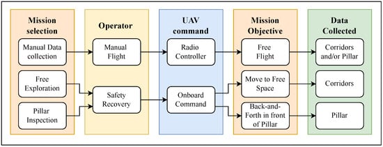
This section describes the design of an UAV for underground mine inspection, discussing the design requirements and engineering decisions. The main objective of this aerial robot is to reliably collect the data required for 3D reconstruction of the mine or parts of the mine. The general data-collection pipeline depends on the mission, as illustrated in Figure 1.
Figure 1.
Data-collection pipeline, based on the mission selection. The UAV expects commands from the operator during manual data collection and from the onboard computer when automated missions are selected. The mission’s final product is a point cloud map of the corridors and/or detailed data for pillar inspection.
3.1. Engineering Requirements
The purpose of the vehicle developed in this project is to collect data from specific stone mine pillars, which may vary in height from 7 to 12 m and in width from 5 to approximately 20 m. To execute the missions illustrated in Figure 1, the vehicle must be:
- Robust to underground conditions (e.g., low light, dust, and no GNSS signals);
- Safe and easy to operate;
- Able to carry different payloads;
- Capable of executing supervised autonomous pillar inspection.
3.2. System Design
Since real-scenario testing and robot deployment are limited, the development strategy was based on the team’s expertise and followed the mechatronic system design approach described in [63]. The first step in designing the system is to translate the user requirements into quantitative measurements. Then, it is important to identify each module needed independently within the domain (electronic, mechanical, or information technology) and its respective quality assurance. The system integration needs to be carried out from the starting module through the complete system. The translation of the system requirements into quantitative ones is outlined in Table 2.
Table 2.
Requirements to Specifications Mapping.
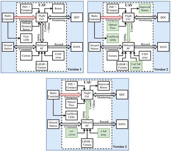
Once the main requirements were set, the iterative process began, with testing and improvement. Three main versions of the robot were deployed and tested in real limestone conditions. Figure 2 shows the iteration process and the updates made throughout the robot versions.
Figure 2.
Three versions of UAV. Changes between platforms are highlighted in green. For version two, the improvements included a new optical flow sensor, forward and downward illumination, improved Rotors and Propellers, a Ceiling distance sensor, and the ability to fly the robot without an onboard computer. Version three has a 360° LiDAR, and the change from 8-point to 3-point + ceil Time-of-Flight (ToF) range sensors.
The initial concept focused on VIO using a standard quadrotor frame and an onboard computer for autonomous data collection. To ensure continuous operation during battery swaps, a hot-swap circuit was integrated. For survivability, we utilized a carbon fiber guard and “physical fuses”—3D-printed parts designed to break on impact to save the electronic components. However, mine deployments revealed that even with high-power lighting, VIO lost tracking in dark, low-texture corridors. Furthermore, the kg drone pushed the propulsion system to its efficiency limits, causing instability as voltage dropped.
Version 2 addresses these efficiency and stability issues. We switched to a more efficient motor-propeller combination, which required extending the frame arms by one inch. We also replaced the VIO reliance with a downward-facing optical flow sensor optimized for low light, and upgraded the landing gear with a carbon fiber skeleton with flexible Thermoplastic Polyurethane (TPU) parts for the rugged mine floor. These changes improved reliability significantly. However, during further validation in the mine, we found that dense dust confused the optical flow sensor. It detected false movement, causing the drone to drift and making positioning unreliable.
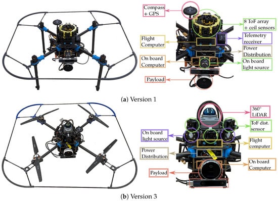
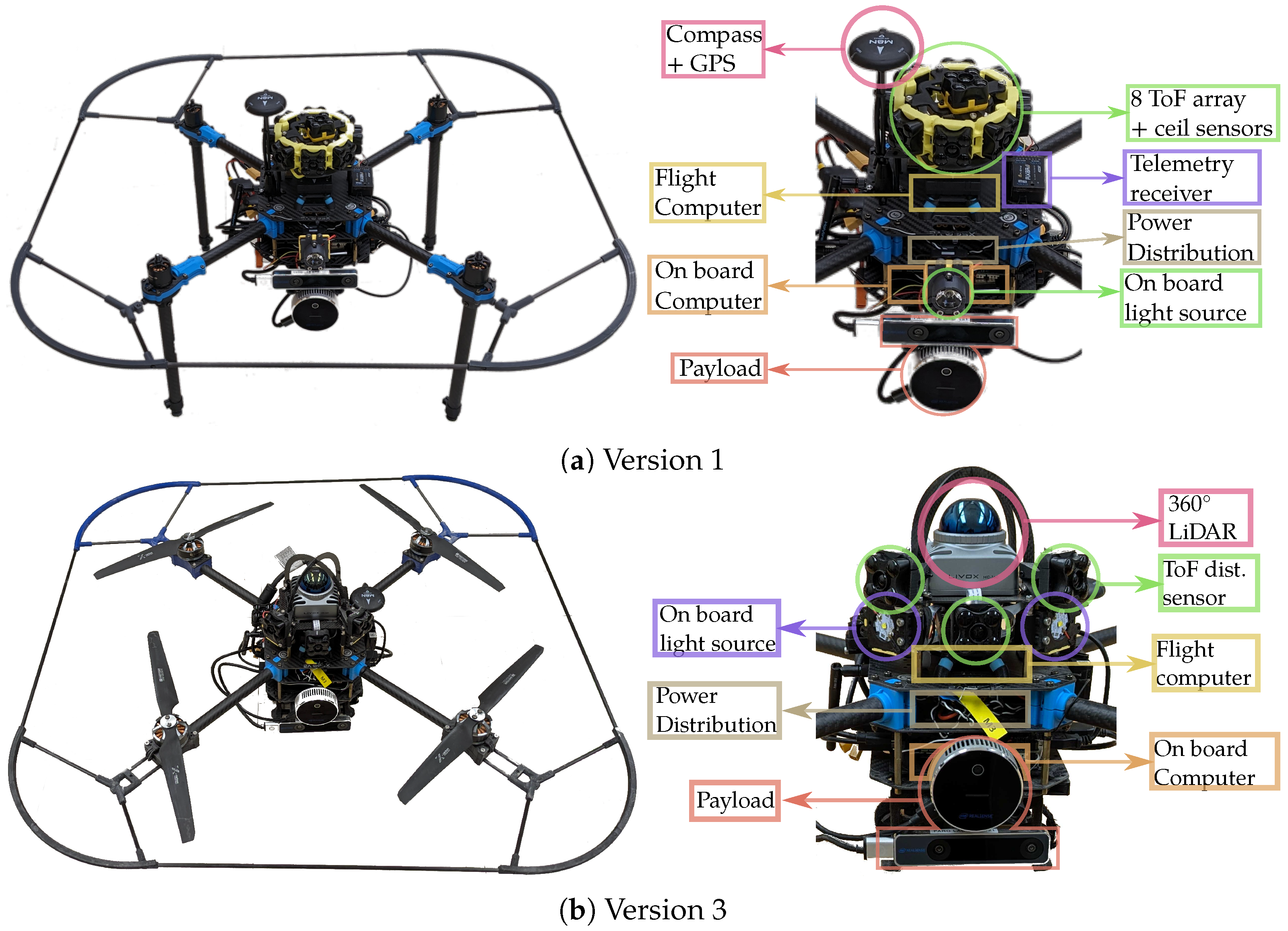
Version 3 finally overcame these environmental limitations by integrating a lightweight 3D LiDAR. This sensor represents an ideal choice due to its lightweight form factor, cost-effectiveness, and ability to operate in total darkness. The upgrade enables LIO [39], providing a robust, drift-free localization required for underground operations. Figure 3 illustrates the evolution from the initial prototype to the final LiDAR-equipped robot.
Figure 3.
Evolution of the UAV platform. (a) Version 1, featuring long landing legs, onboard high-power lamp, 8 ToF array, and a standard payload of RealSense T265 and L515 sensor. (b) Version 3, featuring a low center of gravity compliant landing gear, improved rotor-propellers combo, simplified ToF array, adjustable onboard light source, the 360° LiDAR, and the same payload.
3.3. Sensors and Payload for Data Collection
The sensors mounted on the drone serve two purposes: providing information to the onboard computer and the flight controller for navigation, and collecting data for point cloud reconstruction. The traditional sensors used for drone navigation are primarily IMUs for acceleration, velocity, and position estimation; a barometer for estimating global altitude; a compass to estimate global heading; a GNSS receiver for global positioning; and a downward-facing range sensor for relative altitude. Due to the nature of the underground mines, barometers and compass are unreliable, and GNSS is inaccessible, leaving us to rely solely on IMUs and range sensors. This minimum configuration is enough to fly the vehicle with inherent issues: drifting due to accumulated error and the lack of a global reference frame. These issues ultimately make the system unstable and unreliable for autonomous flights.
To address the accumulated error, two range sensors, one pointing up and one pointing down, were added as a source of vertical positioning information. Additionally, to enrich horizontal navigation information, a low-light-capable optical flow sensor with a Pixart optical motion tracking sensor, capable of operating in low-light conditions (>9 lux), was used. Once the robot was stable for underground flight, additional navigation sensors were added to simplify its behavior and enable automated, low-power navigation. These include a TeraRanger Tower Evo (Terabee, Saint-Genis-Pouilly, France), which consists of an array of eight ToF range sensors that help identify open spaces and explore them without complex algorithms.
The navigation system can be complemented with VIO and/or LIO. One of the most widely accepted cameras for VIO is the Intel RealSense T265 (Intel Corporation, Santa Clara, CA, USA (Made in China)), since it provides an out-of-the-box odometry topic, programmed by the manufacturer. In the first version of the drone, this sensor was used along with the Intel RealSense L515 (Intel Corporation, Santa Clara, CA, USA (Made in China)) solid-state lidar, which provides an accurate Red-Green-Blue-Depth (RGB-D) input for 3D reconstruction. As part of the system update, starting with the second version of the robot, we implemented and tested OpenVINS [35] with multiple cameras to provide a more versatile VIO tailored to environmental conditions. For mission execution, the payload options tested are presented in Table 3. In addition, [64] presents a detailed comparison between the RealSense D415, D455, and L515, showing that the more precise 3D reconstruction comes from RealSense D415. Despite this precision, the sensor was deemed unsuitable for our task because its limited effective range (–3 m) does not meet the operational clearance requirements of our platform. Therefore, we concluded that the L515 LiDAR is the best from the point of view of distance to object and quality of reconstruction.
Table 3.
Comparison of Intel RealSense Sensors tested with our system.
The major adaptation in the third version of the drone was the use of the FAST-LIO2 [39] stack based on data from the Livox Mid 360 LiDAR (Livox Technology Co., Ltd. Shenzhen, China) released in 2023 [65], which has proven to be robust underground, even in complete darkness, dusty, and unknown environments. In this version, a different sensor array can be used for data collection. While the minimum data collected is the recorded point cloud from the mid-360 Livox sensor, any other camera can be used for a close inspection of a pillar. We mostly used the Intel RealSense L515 due to its higher-quality point cloud data from its solid-state LiDAR.
3.4. Hardware Integration
This section provides information on the UAV’s final design and its operation, including flight time and power consumption under controlled conditions.
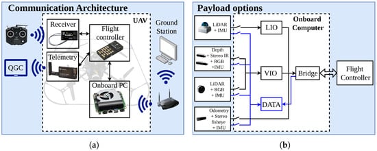
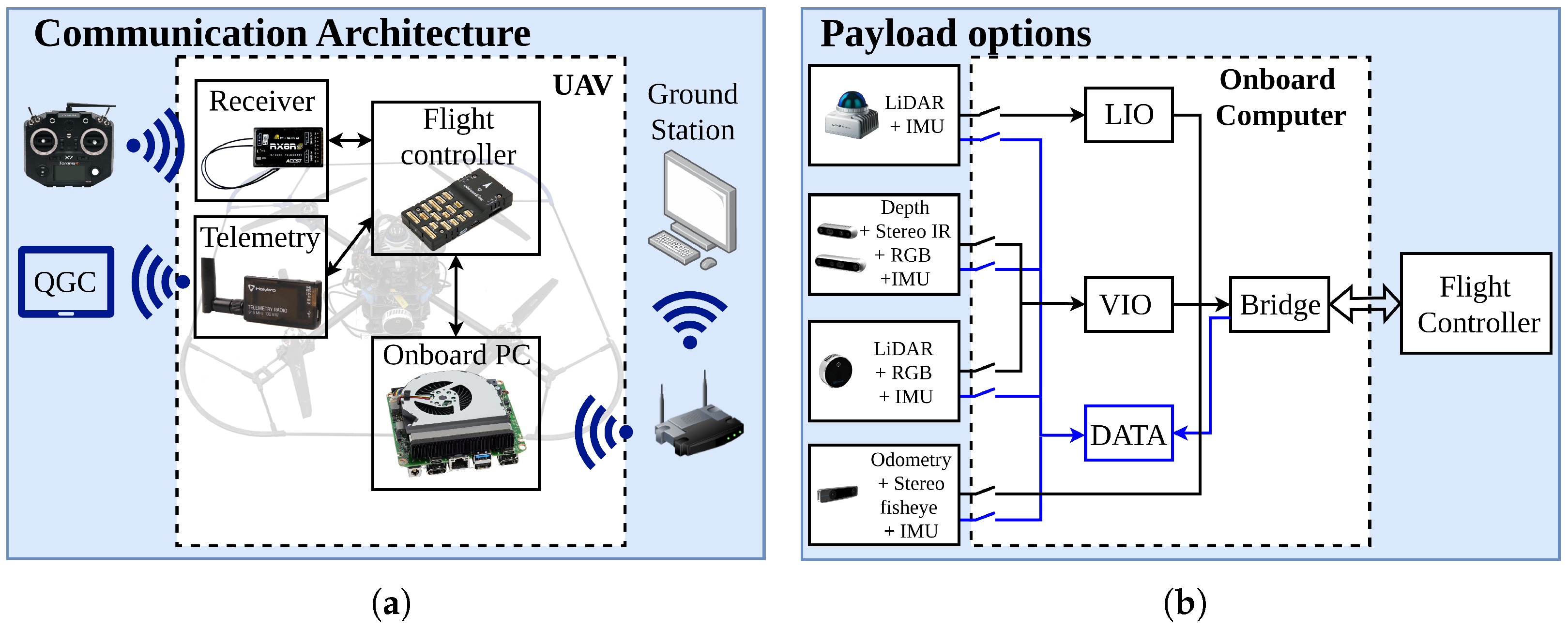
To deploy the UAV, an operator uses a remote controller (RC) for manual data logging or to recover the vehicle in an emergency while supervised autonomous missions run. A standard telemetry connection is established with a tablet running QGroundControl (QGC) [66], which is mounted to the RC to monitor the drone’s status. Additionally, a mobile access point is transported to a remote station, where a secure shell connection is established to monitor, start, and stop the missions. Figure 4a shows this architecture. It is important to note that mission control and the calculations required to generate velocity commands are performed entirely on the onboard computer. Given that the UAV’s primary objective is multi-modal data collection, Figure 4b illustrates the payload configurations tested, demonstrating their capability to either record dataset information or provide real-time odometry estimation for the flight controller.
Figure 4.
(a) Vehicle communication architecture. The UAV connects directly to the RC remote and to a QGroundControl station, whereas the onboard computer communicates with a ground station via Secure Shell. (b) The vehicle’s payload can be selected. Some of the sensors used also serve as a source of odometry to the flight controller.
The UAV employs a parallel power architecture designed to isolate the onboard computer from the flight-critical systems. The main battery source is bifurcated into two distinct power domains:
- Flight Control and Propulsion Domain: The primary branch is routed through a power module (PM02), which serves a dual function: it passes unregulated battery voltage to the propulsion bus, while simultaneously energizing the Flight Management Unit via an integrated 5 V regulation stage. This ensures that the drone’s core stability sensors and actuators operate on the standard, manufacturer-validated power path.
- Regulated 12 V Domain: A secondary parallel branch feeds a dedicated 100 W DC-DC step-down regulator, creating a stable 12 V line. This isolated line powers the onboard computer, sensors, peripherals, and payload, protecting them from voltage sag and electrical noise inherent to the propulsion line.
Table 4 details the designed power consumption, based on the maximums reported in the components’ specifications, versus the actual operational power consumption. It is important to note that the designed propulsion maximum assumes 100% motor usage. In contrast, the measured values reflect the steady-state power required for hover, these data indicate that the UAV requires approximately 67% throttle to hover.
Table 4.
Comparison of Design Maximum Power Estimation and Operational Power Consumption.
Although the motor-propeller combination is highly efficient, it is suboptimal due to the use of polymer propellers rather than carbon fiber ones. The motivation for using polymer propellers is operator safety and durability: in the event of a collision, polymer propellers tend to deform and survive the impact with only minor damage. In contrast, carbon fiber propellers are more efficient but dangerous due to their rigidity and tendency to shatter. With these considerations, the UAV’s flight time is around 6 min with one 5000 mAh battery and 10 min with two batteries.
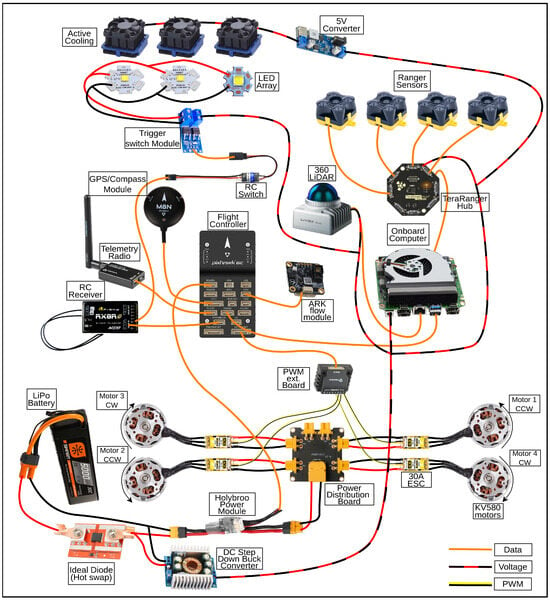
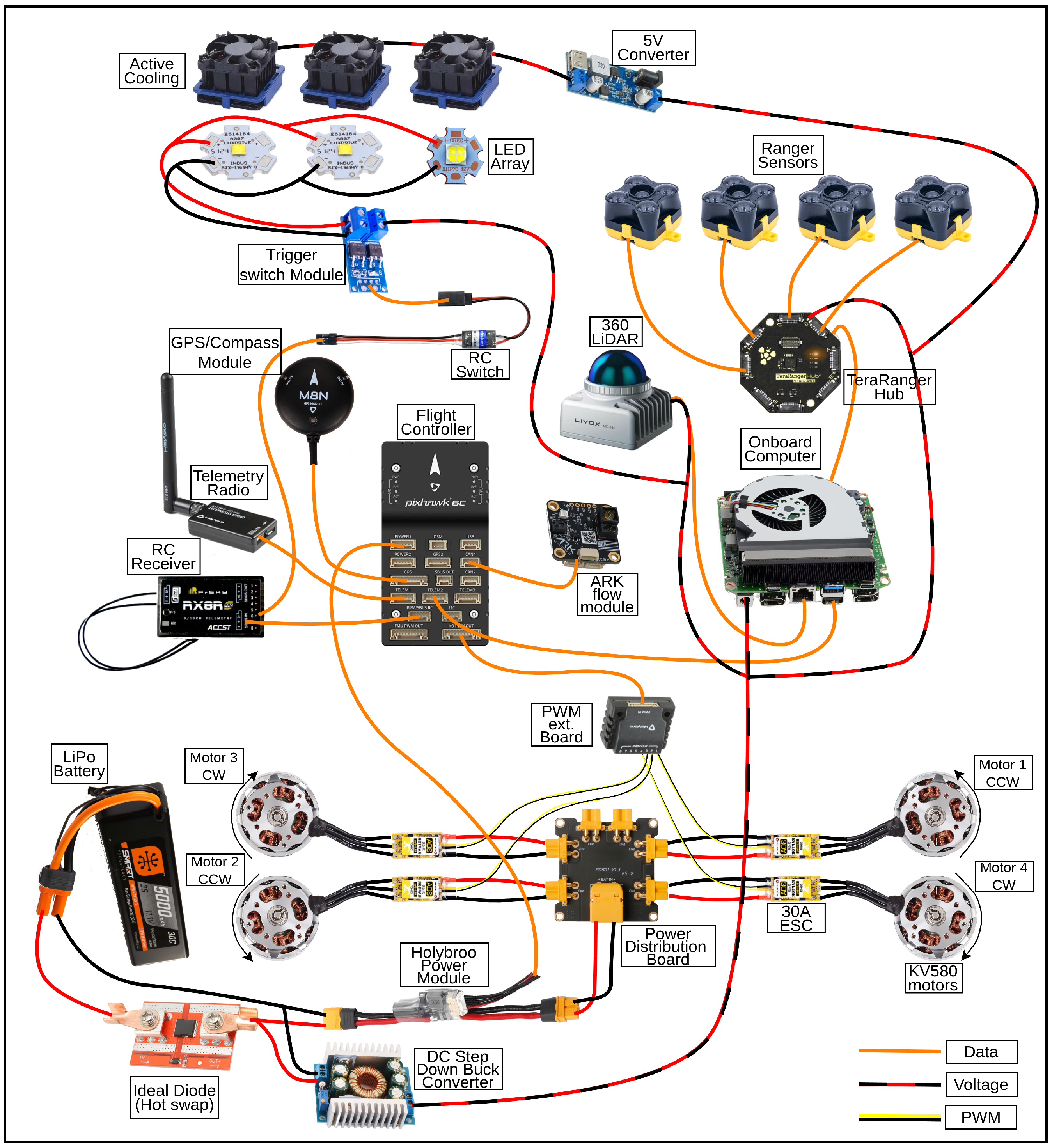
The physical integration of the described hardware results in a total takeoff weight (TOW) of approximately 3385 g, including the 4S 5000 mAh LiPo battery of 465 g. In this configuration, the mission-critical sensors, computing suite, and onboard illumination system, including the Intel NUC (Intel Corporation, Santa Clara, CA, USA (Made in China)), Livox Mid-360, RealSense camera, and high-intensity LED arrays, constitute a payload mass of 675 g, representing 19.94% of the total vehicle mass. This setup provides a maximum static thrust of 1230 g per propeller, yielding a thrust-to-weight ratio of 1.45:1. This ratio ensures sufficient control authority for autonomous obstacle avoidance while maintaining a stable hover at approximately 69% throttle, directly correlating to the operational power consumption levels previously detailed in Table 4. A complete diagram of the final hardware configuration is shown in Figure 5.
Figure 5.
The UAV utilizes a Holybro X500 V2 frame and Pixhawk 6C controller (Holybro (with Auterion), Shenzhen, China / Zurich, CH), integrating telemetry, RC, GPS/compass, and an Ark Flow (ARK Electronics, Indianapolis, IN, USA) sensor. Propulsion features upgraded motors with MS1302 propellers. An onboard Intel NUC i7 processes data from a Livox LiDAR and a TeraRanger Hub linking four sensors (three forward, one upward). An actively cooled lighting system includes two forward LEDs ( lm) and a downward Cree XHP70B ( lm) (Cree LED (SGH), Durham, NC, USA). Power is divided into a high-current and an isolated V electronics line, incorporating a A ideal-diode for hot-swapping.
3.5. Onboard Computing and Control
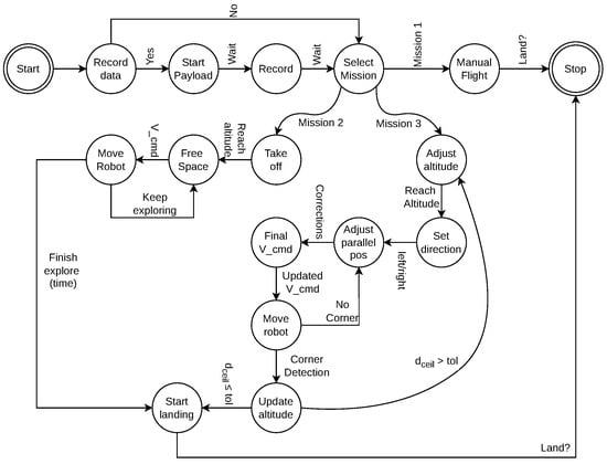
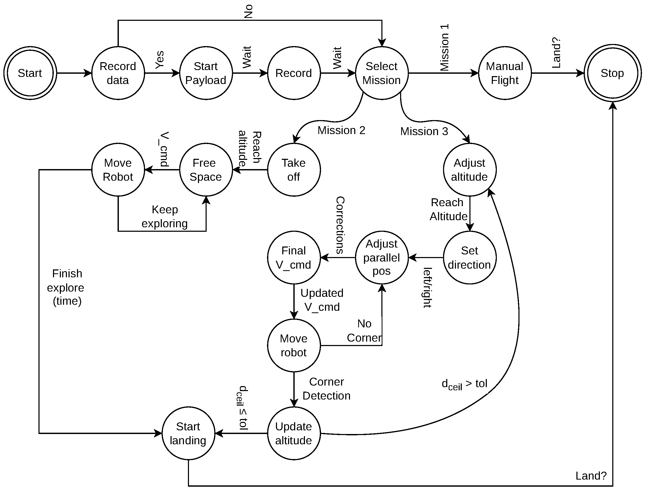
To operate the system with versatility in underground environments, three distinct control modes were developed: manual data collection, reactive exploration, and supervised autonomous pillar inspection. At the software level, the architecture is implemented within a custom ROS 2 Humble [67] package. This package centralizes the required communication bridges, camera and LiDAR drivers, and the core finite-state machine. Each mode is governed by its own FSM, which manages transitions between flight phases, ensuring safety and data integrity. Operationally, the package provides basic launch files for individual component testing, alongside a primary deployment launch file that uses modifiable parameters to configure the mission profile and select the active sensor suite. The state machine with the three modes is shown in Figure 6. Each mode is described next.
Figure 6.
The robot state machine has the initial state to record data, and three different options: manual flight (mission 1), reactive exploration (mission 2), and supervised autonomous inspection (mission 3). In mission 2, the drone takes off to a safe altitude, finds the most open space, adjusts its attitude towards it and move with the commanded velocity toward it. In mission 3, a back-and-forth strategy is utilized to cover the face of a pillar.
3.5.1. Manual Flight and Data Logging
The primary operational mode is manual teleoperation, which serves as both a fallback safety mechanism and a tool for targeted inspection. In this mode, the operator maintains control over the vehicle’s attitude and thrust via a standard RC transmitter. At the same time, the flight controller handles state estimation and stability, while the onboard computer stores sensor data recorded by the robot and the payload. The state machine for this mission decouples flight control from data acquisition. A dedicated “Data recording” mission can be started independently of the flight status, allowing the operator to fly to a region of interest and engage the high-bandwidth recording (LiDAR and cameras) only when necessary.
3.5.2. Autonomous Exploration
The second mode is designed to navigate unknown corridors autonomously, using a lightweight, reactive planner. This mode relies on an 8-point LiDAR tower mounted on the second version of the drone or on the Livox LiDAR mounted in version 3. The algorithm identifies the sector with the largest range and calculates the angular error between the drone’s current heading and the vector pointing to the open area. It works in three steps:
- Sensor Transformation: We transform the LiDAR distance measurements at angles into individual point vectors in the robot’s body frame, in which the x-axis points forward, the y-axis points to the left, and the z-axis points up:
- Calculate open space: We compute the average vector to determine the resultant direction of the free space:
- Command velocity: We extract the desired heading angle and apply a proportional gain to the normalized direction vector to generate the final linear velocity command:
The previous equations only consider the horizontal movement of the drone. While vertical information is also available from the LiDAR sensors mounted on the vehicle, this information is only used at the control level to maintain a constant height.
To compute in Equation (2), we use vectors equally distributed at 45° around the UAV. We intentionally omit the backward-pointing vector to create an unbalanced average that guarantees forward movement. These vectors come directly from the 8-point LiDAR tower in version 2, or are sampled from the Livox LiDAR point cloud in version 3. Consequently, if there is a wall on both sides, the lateral vectors cancel out at the center, and the drone moves forward while keeping its relative position with respect to the walls. A PD controller is implemented to guarantee that the drone stops if it gets too close to a pillar. Since we based this exploration on supervised autonomy, the operator can take control or land the UAV at any moment. This simple exploration technique was implemented to collect main corridor data and test the limits of the onboard sensors, though more sophisticated algorithms, such as [68], are required for a fully autonomous exploration of mines.
3.5.3. Autonomous Pillar Inspection
The third mission focuses on high-resolution 3D reconstruction of specific mine pillars. This mode requires a consistent point density, which is achieved by maintaining a fixed distance and velocity relative to the structure. The drone follows a coverage path planning strategy using a horizontal back-and-forth (sweeping) pattern. Since most pillars are longer in the horizontal direction, a horizontal back-and-forth requires fewer stops at the borders when compared to a vertical sweeping, thus yielding a faster and more efficient coverage. The operator positions the drone in front of the target pillar and initiates the mission. The algorithm adjusts the current distance to the wall and maintains it constant, ensuring complete coverage of the pillar face. To execute the sequence of horizontal passes at incremental altitudes, we use a single-point array of four LiDARs, with three pointing forward to identify corners and one pointing up to measure the distance to the ceiling. Using this combination, the pillar’s limits are identified in real time, keeping the process simple and independent of complex SLAM algorithms.
4. Point Cloud Reconstruction and Modeling
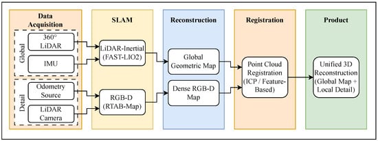
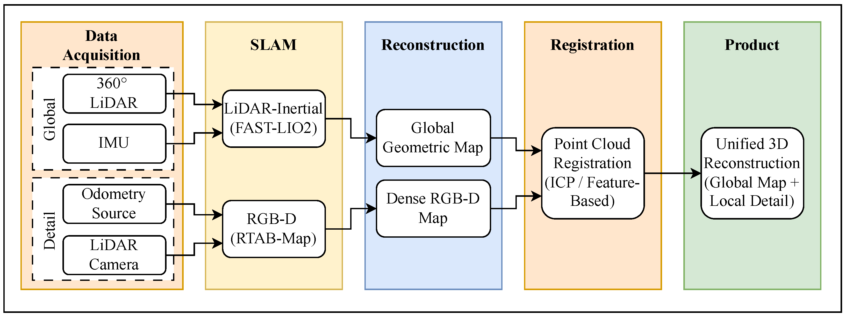
This section details two methodologies. First, it presents the pipeline for processing three-dimensional reconstructions of underground environments by combining LiDAR-based SLAM, RGB-D-based SLAM, and point cloud registration techniques, as shown in Figure 7. Then, it describes the photogrammetry process, which can be used to create high-resolution maps for inspection. The overall objective is to obtain a globally consistent map of the mine while enabling high-resolution inspection of specific structures, such as pillars.
Figure 7.
Overview of the 3D reconstruction pipeline. LiDAR-inertial SLAM provides a globally consistent geometric map, while RGB-D SLAM generates high-resolution local reconstructions. Point cloud registration aligns local models into the global frame to produce a unified 3D map.
4.1. Point Cloud Reconstruction
The initial 3D reconstruction is estimated using RGB-D SLAM and LiDAR-inertial SLAM pipelines. The RGB-D SLAM method estimates camera motion and produces dense maps in real time, while LiDAR-inertial SLAM methods directly reconstruct the environment geometry using range measurements. In this work, RTABMap [69] is used for RGB-D SLAM, while FAST-LIO2 [39] is used for LiDAR–inertial SLAM. RTABMap used synchronized RGB and depth measurements from an Intel RealSense L515 sensor to perform visual reconstruction.
LiDAR-based SLAM is particularly effective in subterranean environments due to its robustness to illumination changes and its ability to capture accurate geometric structure over large areas. As a result, LiDAR SLAM maps typically provide extended spatial coverage, often capturing entire mine sections. However, these maps generally lack fine surface detail, texture, and visual information, which limits their suitability for detailed structural inspection. Visual SLAM methods, while capable of producing visually interpretable maps, are more sensitive to lighting conditions, dust, and texture degradation, which are common in underground settings. Large-scale geometric reconstruction is performed using FAST-LIO2 [39], which estimates motion and mapping directly from range measurements acquired by a Livox mid-360 LiDAR sensor.
The output of this stage is a globally consistent point cloud that serves as the geometric backbone for subsequent reconstruction and refinement steps.
4.2. Point Cloud Registration
To construct a complete 3D map that combines global coverage with local detail, point cloud registration aligns RGB-D-derived reconstructions with the global LiDAR-based SLAM map. This process enables high-resolution local models, such as detailed pillar reconstructions, to be integrated into a unified coordinate frame [43].
The registration pipeline follows a multi-stage approach that combines feature-based initialization and geometric refinement. In the feature-based stage, keypoints are extracted from both source and target point clouds, and Fast Point Feature Histogram (FPFH) [70] descriptors are computed at these points to establish correspondences. An initial rigid transformation is then estimated using a sample-consensus approach [43]. This initial alignment is refined using the Normal Distributions Transform (NDT), which models the reference point cloud as a set of local Gaussian distributions to improve robustness to noise and partial overlap [71]. Finally, Iterative Closest Point (ICP) is applied to minimize point-to-point residual error between the aligned point clouds, producing the final registration [72]. By anchoring locally detailed colored pointclouds to the globally consistent LiDAR map, the resulting reconstruction preserves both large-scale spatial structure and fine surface detail.
This reconstruction strategy allows for efficient mapping of extensive underground environments while supporting detailed inspection of critical structures, balancing scalability, robustness, and reconstruction accuracy.
4.3. Photogrammetry
Photogrammetry is used to estimate high-resolution 3D reconstructions from image data, typically through Structure-from-Motion (SfM) and Multi-View Stereo (MVS) pipelines. In contrast to SLAM-based mapping, photogrammetric reconstruction is performed offline and focuses on producing dense, colored point clouds with detailed surface geometry.
In the proposed workflow, photogrammetry is applied to image data collected during targeted inspection missions, such as close-range scans of mine pillars or structural features of interest. These photogrammetry-derived point clouds provide greater local detail than LiDAR-SLAM maps and capture surface texture and fine geometric variations that are not observable in LiDAR-only reconstructions.
While photogrammetry offers high reconstruction fidelity, it is more computationally demanding and sensitive to imaging conditions. Reconstruction quality depends on sufficient image overlap, stable illumination, and minimal motion blur, and processing time can be substantial for large datasets. For these reasons, photogrammetry is used selectively to enrich the inspection process of specific regions of interest rather than as a standalone solution for large-scale underground mapping.
5. Results
To test and validate the complete system, three types of experiments are performed. We initially fly the drone in an environment equipped with motion-tracking cameras (VICON), which serves as a position ground truth. Then we test the system and missions in a simulated mine environment, and finally deploy them in an operational underground limestone mine.
5.1. Experimental Setup
In all experiments reported in this paper, the robot’s configuration was version 3, with the LIO as input to the EKF-based position estimation of the flight controller. The specific configuration for each component is:
- LIO Algorithm: Uses FAST-LIO2 with default parameters and uses the Livox Mid-360 with its internal IMU.
- VIO Algorithm: Uses OpenVins based on the Intel RealSense D457 (Intel Corporation, Santa Clara, CA, USA (Made in Thailand)).
- Ground truth: VICON motion capture system with 32 cameras providing position tracking at Hz.
5.2. Experiment 1: Ground Truth Validation
For this experiment, the goal was to analyze the accuracy and precision of the VIO and LIO algorithms. The robot carried all necessary payloads while being flown manually inside the motion capture volume. The environment has enough visual texture, which allows for good VIO estimates. A summary of the overall performance is presented in Table 5, which details the combined global error metrics.
Table 5.
Global localization error metrics.
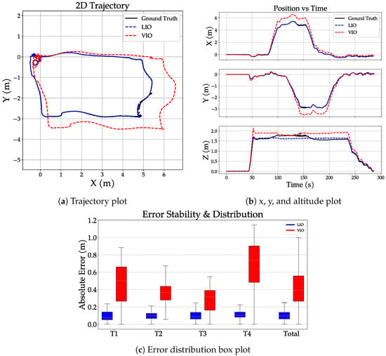
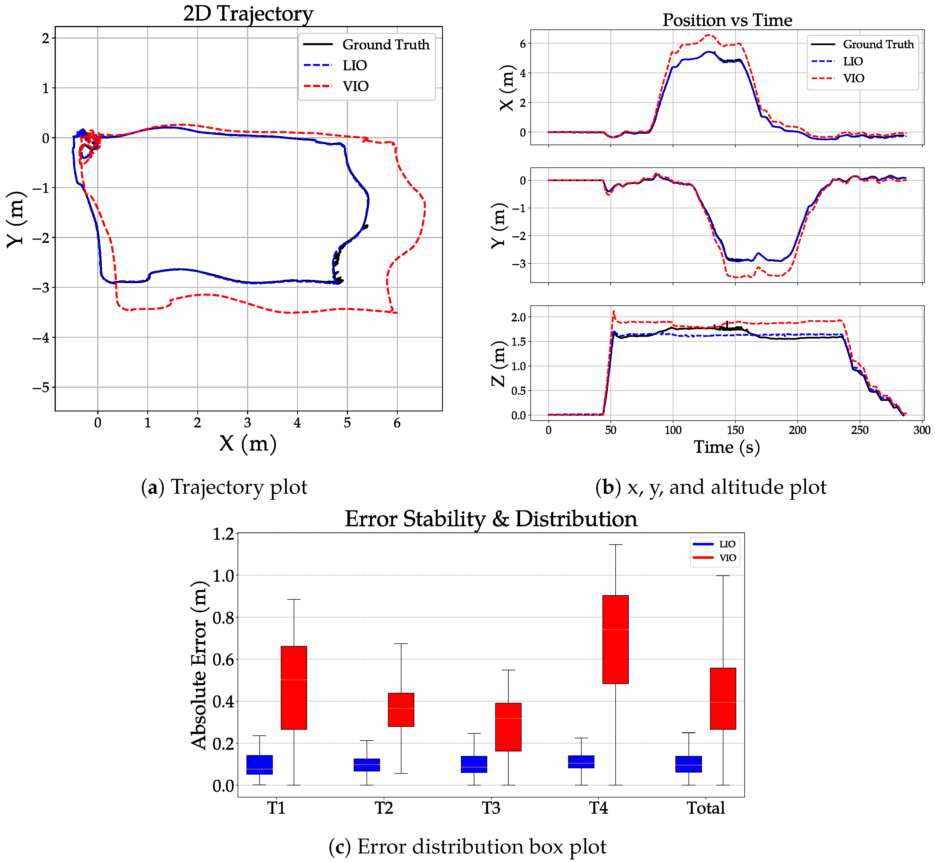
Figure 8a,b show the results of a typical test. Figure 8a presents horizontal trajectories, Figure 8b presents the relative altitude from the starting point. Since the frequency of each method is different (Ground truth 200 Hz, VIO 400 Hz, and LIO 10 Hz), an interpolation of the data was executed to obtain positions in the same reference time and be able to compare them fairly. A frequency of 10 Hz is used for plotting and error calculations. From these figures, we can infer that LIO is more accurate and precise. However, notice that the errors in both cases are small. It can also be observed in Figure 8a that VIO is more susceptible to accumulating errors. Figure 8b shows that LIO estimates a more constant drone altitude than VIO, which is important when this information is used in the flight controller.
Figure 8.
Comparative evaluation of odometry algorithms against VICON motion capture ground truth. (a) Estimated 2D trajectories; (b) Position evolution over time for OpenVins (VIO) [35] and FAST-LIO2 (LIO) [39]; and (c) Absolute error distribution. The results indicate that LIO achieves lower absolute error and standard deviation than VIO under these experimental conditions.
Figure 8c shows results of experiments where the same test was repeated four times to assess repeatability and quantify deviations from the ground truth. The absolute error distribution is presented as a box plot. From this comparison, it is evident that under these controlled conditions, the absolute error of the LIO is significantly smaller than that of the VIO. These results confirm that LIO is both more accurate and precise under the evaluated conditions.
5.3. Experiment 2: Controlled Analog Environment
To validate the proposed 3D reconstruction capabilities of our system, tests were conducted in West Virginia University’s simulated underground coal mine. This facility is about 340 feet long by 110 feet wide and is located at the WVU Academy for Mine Training and Energy Technologies. The facility replicates the geometric constraints of underground coal mines (long corridors, intersections, and limited width) in a controlled setting. Multiple tests were conducted to validate the expected behaviors: manual flight, autonomous exploration, and pillar inspection.
During pillar inspection missions, RGB-D-derived point clouds were estimated using RTABMap [69] from different inspection viewpoints. Camera-to-camera point cloud registration was first evaluated using a pair of independently reconstructed camera maps to validate the registration pipeline. The proposed approach employed Fast Point Feature Histogram (FPFH)-based coarse alignment followed by Normal Distributions Transform (NDT) and ICP refinement.
Registration accuracy was quantified using nearest-neighbor residual statistics between the aligned point clouds. Inliers were defined using an adaptive threshold derived from the robust scale of the residual distribution, estimated via the Median Absolute Deviation (MAD) with Gaussian-consistent scaling, and applying a three-sigma gate. The resulting accuracy metrics for both the camera-to-camera alignment and the multi-modal fusion are summarized in Table 6.
Table 6.
Registration accuracy metrics for point cloud alignment and sensor fusion.
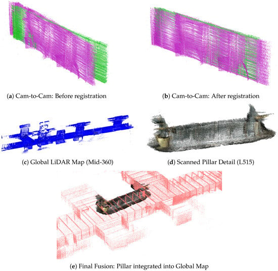
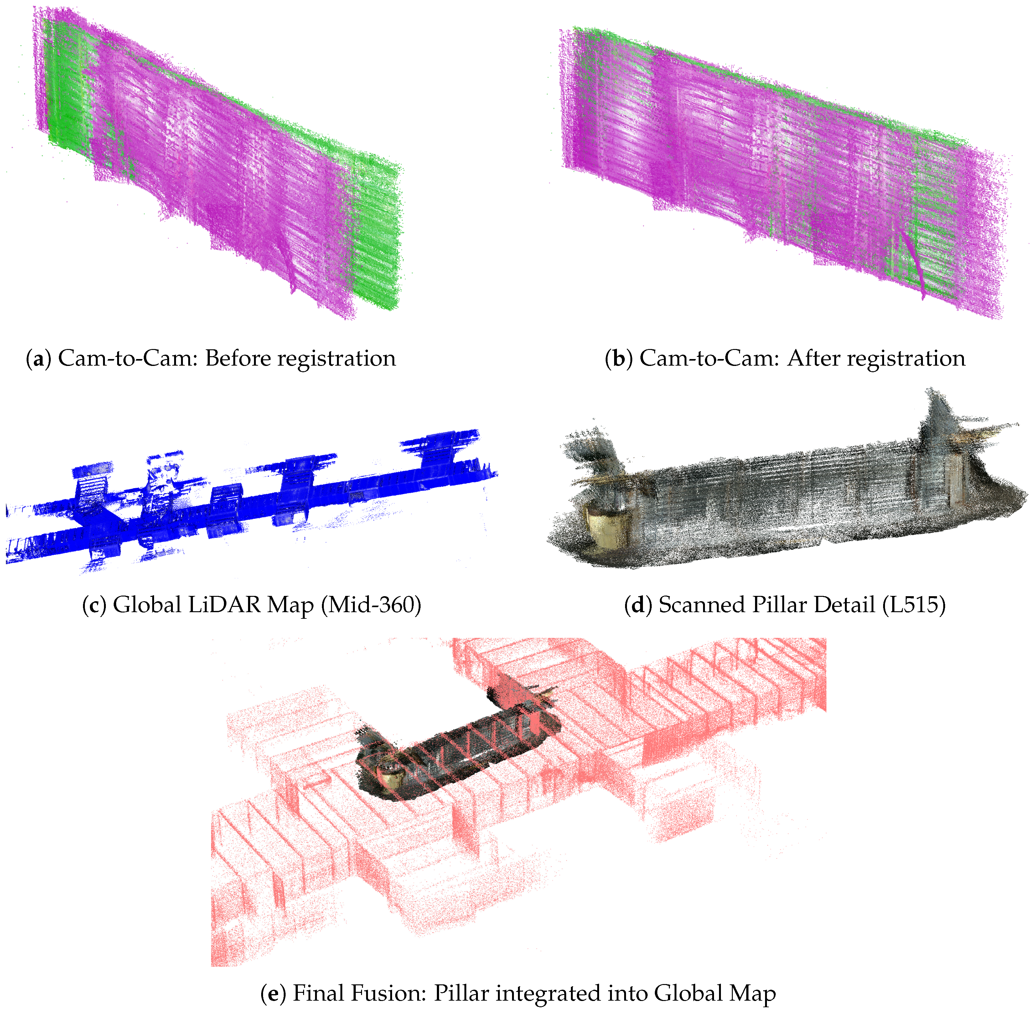
Figure 9a,b show the camera-to-camera registration results before and after alignment. Figure 9c displays the global point cloud of an entire corridor of the simulated mine, using data collected by the Livox Mid-360 sensor. Figure 9d presents a detailed scan of a pillar using RealSense L515 depth and RGB imagery. Figure 9e shows the extended point cloud registered with the 360° LiDAR and a detailed view of one of the pillars using RealSense L515. As noted in Table 6, the higher residual error in the RGB-D to LiDAR fusion compared to the camera-to-camera case is likely due to cross-sensor differences and partial geometric overlap between the LiDAR map and the RGB-D reconstruction.
Figure 9.
Multi-stage point cloud registration results. (a,b) show the alignment of camera frames; (c,d) display the independent global mine map and the detailed pillar scan; and (e) demonstrates the final Cam-to-LiDAR registration.
5.4. Experiment 3: Active Limestone Mine Deployment
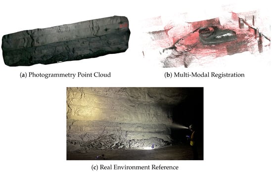
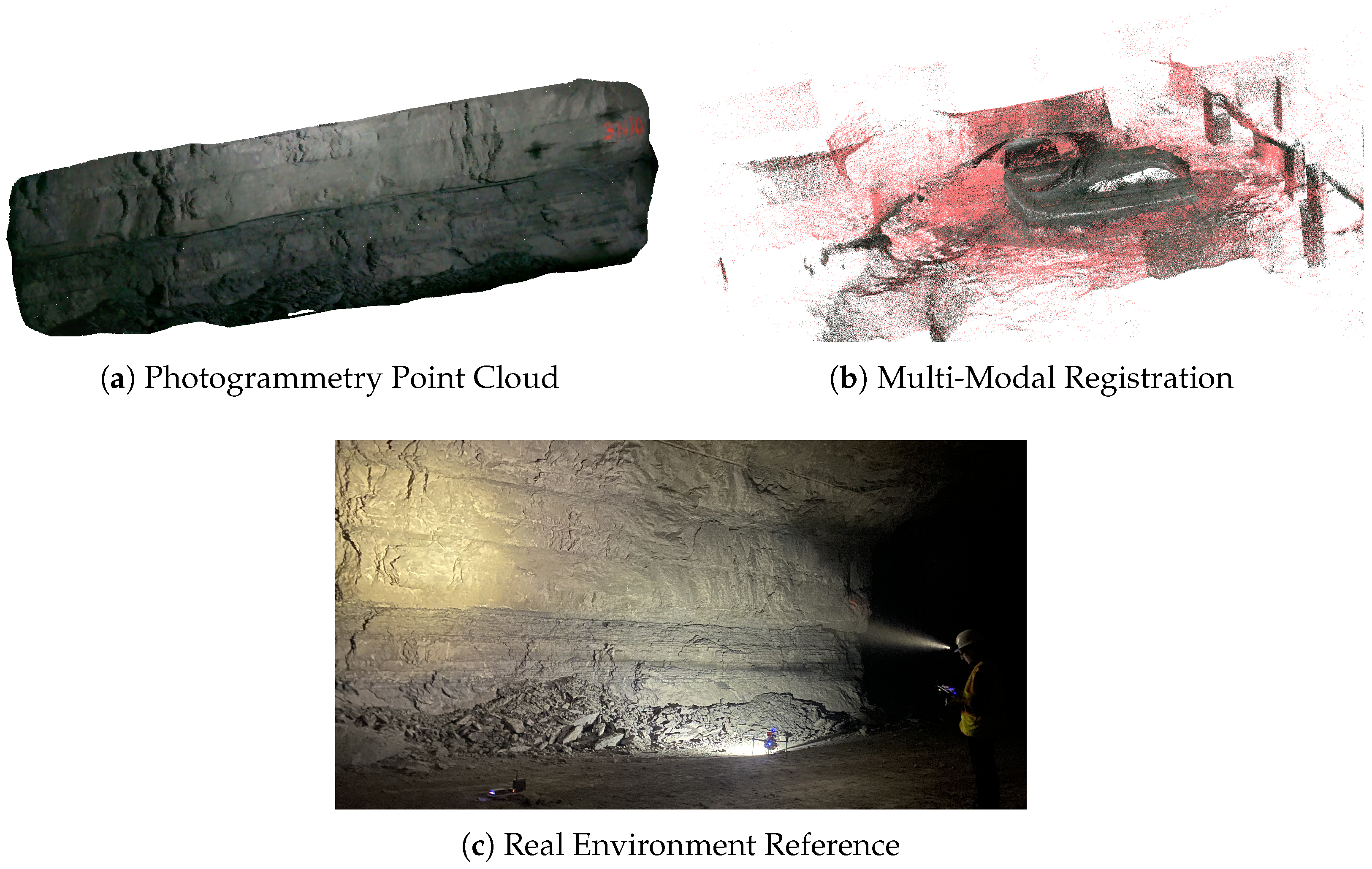
Several experiments were conducted during multiple visits to the same operating stone mine. The number one priority on the mine deployment is data collection and inspection of a given pillar. To ensure safety, a process for adjusting controller parameters, such as the supervised autonomous scan velocity, the vertical distance for back-and-forth scans, and the corner detection sensitivity, must be implemented before deployment. After calibration, the sweeping pattern is performed while the drone maintains a distance of 4 m. In the visited mine, the pillars tend to be wider than they are tall, justifying a vertical back-and-forth scanning strategy. It is important to note that the data-collection distance depends directly on the minimum resolution expected in the reconstruction, based on the camera’s properties. An example of a point cloud reconstructed using the photogrammetry approach is shown in Figure 10a. To capture this kind of data, stable, external illumination is required, and any RGB camera can be used. In this case, the RGB sensor of the RealSense L515 was used.
Figure 10.
(a) Point cloud of a pillar estimated using photogrammetry. (b) Point cloud estimated by the registration of two different sensors: a global LiDAR point cloud generated with FAST-LIO2 (red), and a detailed reconstruction from a solid-state LiDAR with an RGB camera using RTAB-Map (textured). (c) Photograph of the actual pillar.
Figure 10b presents a composite visualization of point clouds from two independent flights. The first dataset represents a manual flight recording of Livox Mid-360 LiDAR. The second represents an automated pillar inspection, in which an Intel RealSense L515 captures depth and RGB imagery. By applying the registration methodology, a final multi-modal map is estimated. This map integrates the general structure of the underground mine with a detailed, texturized point cloud of the inspected pillar. Quantitatively, the fusion achieved an inlier RMSE of m with an inlier percentage of , corresponding to an adaptive residual threshold of m. The increased residual error relative to earlier experiments is likely due to the larger spatial extent of the mine deployment and the reduced overlap between independently acquired datasets.
6. Discussion
This paper presented two main contributions. First, it describes the hardware integration of a UAV platform designed to carry a custom payload while withstanding the harsh environmental conditions of an underground mine. Second, the implementation of a multi-modal 3D reconstruction pipeline is presented and evaluated.
Rather than employing computationally expensive dynamic sensor switching, the proposed drone architecture prioritizes reliability by selecting the appropriate localization pipeline (VIO or LIO) pre-flight via ROS 2 launch files based on specific payload and mission requirements. By executing distinct flight missions, the system captures a global topology of the mine during one mission, and performs targeted autonomous inspections to reconstruct detailed, texturized 3D models of specific pillars in another. To contextualize the system-level trade-offs and limitations observed during these deployments, Table 7 provides a consolidated summary of the UAV’s physical and operational performance metrics.
Table 7.
Consolidated System Performance Summary.
The resulting system demonstrated a high degree of flexibility, successfully operating in multiple flight modes: a manual stable flight with data logging and two supervised autonomous modes. Data collection was validated in both manual and autonomous flights, showing that the platform can serve as a reliable tool for both active remote inspection and autonomous data logging. The system’s modular adaptability allowed for flight stability with varying estimation sources. In the absence of any external odometry estimation, the flight controller fuses the information from their sensors with the velocity estimation of the optical flow. When VIO or LIO is accessible, either one can be used as a reference. VIO is recommended in well-illuminated and texturized environments, whereas LIO is recommended in environments with poor lighting.
A significant portion of the drone development focused on comparing the efficacy of VIO against LIO in harsh conditions. While VIO showed promise in controlled environments, our results indicate that LIO remains superior for subterranean operations. This aligns with current state-of-the-art hardware limitations. The visual algorithms frequently suffered from drift or tracking loss due to the low-texture walls and intermittent lighting characteristic of the mine. In contrast, LIO provided robust, low-drift localization regardless of visual conditions. However, VIO remains a viable, lightweight, and less expensive alternative for specific sectors of the mine, where artificial lighting is present, or for surface-level inspections where GNSS is still denied but visibility is high.
The additional contribution of this research is the integration of distinct sensor payloads to generate multi-modal maps under uncontrolled harsh conditions. By merging the global, large point clouds estimated by the mid-range LiDAR with the high-resolution, texture-rich scans from the depth camera, the system produced a comprehensive digital model of the environment. This mapping approach offers the “best of both worlds”: the structural accuracy required for mine surveying and the visual detail needed to inspect specific pillars or geological features.
Based on our field tests, general guidelines for payload selection can be established to maximize mission efficiency:
- Deep Mine / Dark Zones: LIO configuration (e.g., using Livox Mid-360) is required. The weight penalty is justified by the necessity of active sensing in total darkness.
- Well-Lit / Infrastructure Inspection: For inspections in lit corridors or near light sources, the VIO configuration (e.g., using RealSense L515, RealSense D457, or RealSense D435i) is preferable. This reduces the total weight, as the inspection payload is simultaneously used for navigation.
- Multi-modal Missions: For complex scenarios requiring both global navigation and detailed inspection, the combined payload is effective. The operator must account for the reduced battery life due to the additional weight and plan for separate, sequential flight missions (e.g., one for global mapping and one for pillar inspection) rather than a single continuous flight.
While the developed platform is functional, field deployment highlighted areas for hardware improvement. Beyond hardware constraints, environmental factors such as airborne dust were effectively mitigated by the Livox Mid-360’s internal filtering, which maintained localization stability even under high-particulate conditions. However, the complete absence of ambient light in certain sectors still required the use of high-power onboard LEDs for RGB-D data collection, thereby increasing the total power consumption. The current frame size, while stable and standard, imposes weight penalties that limit flight endurance. A more compact, foldable frame design would enhance portability and maneuverability. Additionally, battery selection remains a critical trade-off. Transitioning to higher-energy-density Li-Ion batteries could double the capacity of current Li-Po equivalents with only a minor weight increase, further extending operational range. Ultimately, despite these hardware and environmental trade-offs, the system demonstrates a viable and robust methodology for subterranean inspection, bridging the gap between experimental UAV research and the practical requirements of the mining industry.
Author Contributions
Conceptualization, L.E., D.A., J.N.G. and G.A.S.P.; methodology, L.E., D.A., J.N.G. and G.A.S.P.; software, L.E. and D.A.; validation, L.E. and D.A.; formal analysis, L.E., D.A., J.N.G. and G.A.S.P.; investigation, L.E., D.A., J.N.G. and G.A.S.P.; resources, J.N.G. and G.A.S.P.; data curation, L.E. and D.A.; writing—original draft preparation, L.E. and D.A.; writing—review and editing, L.E., D.A., J.N.G. and G.A.S.P.; visualization, L.E. and D.A.; supervision, J.N.G. and G.A.S.P.; project administration, J.N.G. and G.A.S.P.; funding acquisition, J.N.G. and G.A.S.P. All authors have read and agreed to the published version of the manuscript.
Funding
This study was sponsored by the Alpha Foundation for the Improvement of Mine Safety and Health, Inc. (ALPHA FOUNDATION) grant number AFCTG22R2-159. The views, opinions, and recommendations expressed herein are solely those of the authors and do not imply any endorsement by ALPHA FOUNDATION, its directors, or its staff.
Informed Consent Statement
Not applicable.
Data Availability Statement
The data for this study are available from the corresponding author upon request.
Acknowledgments
The authors would like to thank our collaborators on the research project, Ihsan “Berk” Tulu, Deniz Tuncay, Richard Bishop, Yu Gu, and several WVU Robotics students. Special thanks go to our collaborators in the stone mine and WVU’s Experimental Coal Mine.
Conflicts of Interest
The authors declare no conflicts of interest.
Abbreviations
The following abbreviations are used in this manuscript:
| 3D | Three dimensional |
| DARPA | United States Defense Advanced Research Projects Agency |
| EKF | Extended Kalman Filter |
| FSM | Finite-state machine |
| GPS | Global Positioning System |
| GNSS | Global Navigation Satellite System |
| ICP | Interactive Closest Point |
| IMU | Inertial Measurement Unit |
| LiDAR | Light Detection and Ranging |
| LIO | LiDAR Inertial Odometry |
| MAD | Median Absolute Deviation |
| MVS | Multi-View Stereo |
| QGC | QGroundControl |
| RC | Remote controller |
| RGB-D | Red, Green, Blue, and Depth |
| RMSE | Root Mean Square Error |
| SfM | Structure from Motion |
| SLAM | Simultaneous Localization and Mapping |
| ToF | Time of Flight |
| TOW | Take-off Weight |
| UAV | Unmanned Aerial Vehicle |
| UGV | Unmanned Ground Vehicles |
| VIO | Visual Inertial Odometry |
| WVU | West Virginia University |
References
- Zheng, J.; Tan, J.; Chen, G. Research on UAV coverage path planning in building visual inspection. J. Build. Eng. 2025, 111, 113556. [Google Scholar] [CrossRef] [Scilit]
- Chen, X.; Wu, Y.; Xu, S. Mission planning of UAVs and UGV for building inspection in rural area. Algorithms 2024, 17, 177. [Google Scholar] [CrossRef] [Scilit]
- Liang, H.; Lee, S.C.; Bae, W.; Kim, J.; Seo, S. Towards UAVs in construction: Advancements, challenges, and future directions for monitoring and inspection. Drones 2023, 7, 202. [Google Scholar] [CrossRef] [Scilit]
- Halder, S.; Afsari, K. Robots in inspection and monitoring of buildings and infrastructure: A systematic review. Appl. Sci. 2023, 13, 2304. [Google Scholar] [CrossRef] [Scilit]
- Guebsi, R.; Mami, S.; Chokmani, K. Drones in precision agriculture: A comprehensive review of applications, technologies, and challenges. Drones 2024, 8, 686. [Google Scholar] [CrossRef] [Scilit]
- Shahmoradi, J.; Talebi, E.; Roghanchi, P.; Hassanalian, M. A comprehensive review of applications of drone technology in the mining industry. Drones 2020, 4, 34. [Google Scholar] [CrossRef] [Scilit]
- Nordström, S.; Stathoulopoulos, N.; Dahlquist, N.; Lindqvist, B.; Tevetzidis, I.; Kanellakis, C.; Nikolakopoulos, G. Safety Inspections and Gas Monitoring in Hazardous Mining Areas Shortly After Blasting Using Autonomous UAVs. J. Field Robot. 2025, 42, 2076–2094. [Google Scholar] [CrossRef] [Scilit]
- Höhrová, P.; Soviar, J.; Sroka, W. Market analysis of drones for civil use. LOGI Sci. J. Transp. Logist. 2023, 14, 55–65. [Google Scholar] [CrossRef] [Scilit]
- Parhusip, A.; Hutauruk, B.; Meigy, E.; Widodo, A.M. Use of drones with LiDAR Technology in Pt. Freeport Indonesia underground mines. In Proceedings of the TPT XXX and 11th Congress of PERHAPI (Association of Indonesian Mining Professionals), Jakarta, Indonesia, 26–28 October 2021; pp. 1–16. [Google Scholar]
- Konieczna-Fuławka, M.; Koval, A.; Nikolakopoulos, G.; Fumagalli, M.; Santas Moreu, L.; Vigara-Puche, V.; Müller, J.; Prenner, M. Autonomous mobile inspection robots in deep underground mining—The current state of the art and future perspectives. Sensors 2025, 25, 3598. [Google Scholar] [CrossRef] [Scilit] [PubMed]
- Arafat, M.Y.; Alam, M.M.; Moh, S. Vision-based navigation techniques for unmanned aerial vehicles: Review and challenges. Drones 2023, 7, 89. [Google Scholar] [CrossRef] [Scilit]
- Skydio, Inc. Skydio X10: Autonomous Drone. Available online: https://www.skydio.com/x10 (accessed on 20 January 2026).
- Flyability. Elios 3: Indoor Inspection Drone. Available online: https://www.flyability.com/elios-3 (accessed on 20 January 2026).
- Brown, L.; Clarke, R.; Akbari, A.; Jovan, F.; Marafie, J.; Marjanovic, O.; Bernardini, S.; Richardson, T.; Watson, S. Subterranean Mine Inspection Using the Prometheus Re-Configurable Drone. J. Field Robot. 2025. [Google Scholar] [CrossRef] [Scilit]
- Tranzatto, M.; Mascarich, F.; Bernreiter, L.; Godinho, C.; Camurri, M.; Khattak, S.; Dang, T.; Reijgwart, V.; Loeje, J.; Wisth, D.; et al. Cerberus: Autonomous legged and aerial robotic exploration in the tunnel and urban circuits of the DARPA Subterranean Challenge. arXiv 2022, arXiv:2201.07067. [Google Scholar] [CrossRef] [Scilit]
- Martinez Rocamora, B., Jr.; Lima, R.R.; Samarakoon, K.; Rathjen, J.; Gross, J.N.; Pereira, G.A. Oxpecker: A tethered UAV for inspection of stone-mine pillars. Drones 2023, 7, 73. [Google Scholar] [CrossRef] [Scilit]
- Lima, R.R.; Pereira, G.A. A multi-model framework for tether-based drone localization. J. Intell. Robot. Syst. 2023, 108, 20. [Google Scholar] [CrossRef] [Scilit]
- Tatsch, C.; Bredu, J.A.; Covell, D.; Tulu, I.B.; Gu, Y. Rhino: An autonomous robot for mapping underground mine environments. In Proceedings of the 2023 IEEE/ASME International Conference on Advanced Intelligent Mechatronics (AIM), Seattle, WA, USA, 28 June–1 July 2023; pp. 1166–1173. [Google Scholar]
- Zhironkina, O.; Zhironkin, S. Technological and intellectual transition to mining 4.0: A review. Energies 2023, 16, 1427. [Google Scholar] [CrossRef] [Scilit]
- Ellmann, A.; Kütimets, K.; Varbla, S.; Väli, E.; Kanter, S. Advancements in underground mine surveys by using SLAM-enabled handheld laser scanners. Surv. Rev. 2022, 54, 363–374. [Google Scholar] [CrossRef] [Scilit]
- Fahle, L.; Holley, E.A.; Walton, G.; Petruska, A.J.; Brune, J.F. Analysis of SLAM-based lidar data quality metrics for geotechnical underground monitoring. Min. Metall. Explor. 2022, 39, 1939–1960. [Google Scholar] [CrossRef] [Scilit]
- Thrun, S.; Thayer, S.; Whittaker, W.; Baker, C.; Burgard, W.; Ferguson, D.; Hahnel, D.; Montemerlo, D.; Morris, A.; Omohundro, Z.; et al. Autonomous exploration and mapping of abandoned mines. IEEE Robot. Autom. Mag. 2004, 11, 79–91. [Google Scholar] [CrossRef] [Scilit]
- Escobar, L.; Pereira, G.A. Energy-Aware Coverage Path Planner for Multirotor UAVS. In Proceedings of the 2025 International Conference on Unmanned Aircraft Systems (ICUAS), Charlotte, NC, USA, 14–17 May 2025; pp. 777–784. [Google Scholar]
- Akhihiero, D.; Olawoye, U.; Das, S.; Gross, J. Cooperative localization for GNSS-denied subterranean navigation: A UAV–UGV team approach. NAVIGATION J. Inst. Navig. 2024, 71, 4. [Google Scholar] [CrossRef] [Scilit]
- Papachristos, C.; Khattak, S.; Mascarich, F.; Alexis, K. Autonomous navigation and mapping in underground mines using aerial robots. In Proceedings of the 2019 IEEE Aerospace Conference, Big Sky, MT, USA, 2–9 March 2019; pp. 1–8. [Google Scholar]
- Li, H.; Savkin, A.V.; Vucetic, B. Autonomous area exploration and mapping in underground mine environments by unmanned aerial vehicles. Robotica 2020, 38, 442–456. [Google Scholar] [CrossRef] [Scilit]
- Rubio-Sierra, C.; Domínguez, D.; Gonzalo, J.; Escapa, A. Path planner for autonomous exploration of underground mines by aerial vehicles. Sensors 2020, 20, 4259. [Google Scholar] [CrossRef] [Scilit]
- Exyn Technologies. ExynAero: Fully Autonomous Aerial Robot for Underground Mining. 2023. Available online: https://www.exyn.com/underground-drone-mapping (accessed on 4 March 2026).
- Emesent. Hovermap: Autonomous LiDAR Mapping Payload. 2022. Available online: https://emesent.com/emesent-product/hovermap-series/ (accessed on 4 March 2026).
- Marković, L.; Kovač, M.; Milijas, R.; Car, M.; Bogdan, S. Error state extended Kalman filter multi-sensor fusion for unmanned aerial vehicle localization in gps and magnetometer denied indoor environments. In Proceedings of the 2022 International Conference on Unmanned Aircraft Systems (ICUAS), Dubrovnik, Croatia, 21–24 June 2022; pp. 184–190. [Google Scholar]
- Abate, M.; Chang, Y.; Hughes, N.; Carlone, L. Kimera2: Robust and accurate metric-semantic SLAM in the real world. In Proceedings of the International Symposium on Experimental Robotics, Melia, Chiang Mai, Thailand, 26–30 November 2024; pp. 81–95. [Google Scholar]
- Mur-Artal, R.; Tardós, J.D. Orb-slam2: An open-source slam system for monocular, stereo, and rgb-d cameras. IEEE Trans. Robot. 2017, 33, 1255–1262. [Google Scholar] [CrossRef] [Scilit]
- He, M.; Rajkumar, R.R. Extended VINS-MONO: A systematic approach for absolute and relative vehicle localization in large-scale outdoor environments. In Proceedings of the 2021 IEEE/RSJ International Conference on Intelligent Robots and Systems (IROS), Prague, Czech Republic, 27 September–1 October 2021; pp. 4861–4868. [Google Scholar]
- Bloesch, M.; Burri, M.; Omari, S.; Hutter, M.; Siegwart, R. Iterated extended Kalman filter based visual-inertial odometry using direct photometric feedback. Int. J. Robot. Res. 2017, 36, 1053–1072. [Google Scholar] [CrossRef] [Scilit]
- Geneva, P.; Eckenhoff, K.; Lee, W.; Yang, Y.; Huang, G. Openvins: A research platform for visual-inertial estimation. In Proceedings of the 2020 IEEE International Conference on Robotics and Automation (ICRA), Virtually, 31 May–31 August 2020; pp. 4666–4672. [Google Scholar]
- Wang, W.; Zhang, Q.; Hu, Y.; Gallay, M.; Zheng, W.; Guo, J. Recent advances in SLAM for degraded environments a review. IEEE Sens. J. 2025, 25, 27898–27921. [Google Scholar] [CrossRef] [Scilit]
- Zhang, J.; Singh, S. LOAM: Lidar odometry and mapping in real-time. In Proceedings of the Robotics: Science and Systems, Berkeley, CA, USA, 12–16 July 2014; Volume 2, pp. 1–9. [Google Scholar]
- Shan, T.; Englot, B.; Meyers, D.; Wang, W.; Ratti, C.; Rus, D. Lio-sam: Tightly-coupled lidar inertial odometry via smoothing and mapping. In Proceedings of the 2020 IEEE/RSJ International Conference on Intelligent Robots and Systems (IROS), Las Vegas, NV, USA, 25–29 October 2020; pp. 5135–5142. [Google Scholar]
- Xu, W.; Cai, Y.; He, D.; Lin, J.; Zhang, F. Fast-lio2: Fast direct lidar-inertial odometry. IEEE Trans. Robot. 2022, 38, 2053–2073. [Google Scholar] [CrossRef] [Scilit]
- Herrera-Granda, E.P.; Torres-Cantero, J.C.; Rosales, A.; Peluffo-Ordóñez, D.H. A comparison of monocular visual SLAM and visual odometry methods applied to 3D reconstruction. Appl. Sci. 2023, 13, 8837. [Google Scholar] [CrossRef] [Scilit]
- Cadena, C.; Carlone, L.; Carrillo, H.; Latif, Y.; Scaramuzza, D.; Neira, J.; Reid, I.; Leonard, J.J. Past, present, and future of simultaneous localization and mapping: Toward the robust-perception age. IEEE Trans. Robot. 2017, 32, 1309–1332. [Google Scholar] [CrossRef] [Scilit]
- Olawoye, U.; Akhihiero, D.; Gross, J.N. Experimental Analysis of Quadcopter Drone Hover Constraints for Localization Improvements. In Proceedings of the 2025 IEEE/ION Position, Location and Navigation Symposium (PLANS), Salt Lake City, UT, USA, 28 April–1 May 2025; pp. 1424–1428. [Google Scholar]
- Akhihiero, D.; Gross, J.N. A Pointcloud Registration Framework for Relocalization in Subterranean Environments. In Proceedings of the 2025 IEEE/ION Position, Location and Navigation Symposium (PLANS), Salt Lake City, UT, USA, 28 April–1 May 2025; pp. 1257–1264. [Google Scholar]
- Agueera-Vega, F.; Carvajal-Ramirez, F.; Martínez-Carricondo, P.; López, J.S.H.; Mesas-Carrascosa, F.J.; García-Ferrer, A.; Pérez-Porras, F.J. Reconstruction of extreme topography from UAV structure from motion photogrammetry. Measurement 2018, 121, 127–138. [Google Scholar] [CrossRef] [Scilit]
- Tonkin, T.N.; Midgley, N.G. Ground-control networks for image based surface reconstruction: An investigation of optimum survey designs using UAV derived imagery and structure-from-motion photogrammetry. Remote Sens. 2016, 8, 786. [Google Scholar] [CrossRef] [Scilit]
- Cline, M.; Rosenmeier, M.; Cline, K. Landform-to microstructural-scale visualization and analysis of fault zones: Use of unmanned aerial vehicles and structure from motion photogrammetry for topographic analyses. In Proceedings of the 2017 Structural Mechanics in Reactor Technology (SMiRT), IASMiRT, Busan, Republic of Korea, 20–25 August 2017. [Google Scholar]
- Macario Barros, A.; Michel, M.; Moline, Y.; Corre, G.; Carrel, F. A comprehensive survey of visual slam algorithms. Robotics 2022, 11, 24. [Google Scholar] [CrossRef] [Scilit]
- Cieslewski, T.; Choudhary, S.; Scaramuzza, D. Data-efficient decentralized visual SLAM. In 2018 IEEE International Conference on Robotics and Automation (ICRA); IEEE: Piscataway, NJ, USA, 2018; pp. 2466–2473. [Google Scholar]
- Liao, Z.; Wang, W.; Qi, X.; Zhang, X. RGB-D object SLAM using quadrics for indoor environments. Sensors 2020, 20, 5150. [Google Scholar] [CrossRef] [Scilit] [PubMed]
- Milford, M.; George, A. Featureless visual processing for SLAM in changing outdoor environments. In Field and Service Robotics; Springer: Berlin/Heidelberg, Germany, 2014; pp. 569–583. [Google Scholar]
- Yousif, K.; Bab-Hadiashar, A.; Hoseinnezhad, R. An overview to visual odometry and visual SLAM: Applications to mobile robotics. Intell. Ind. Syst. 2015, 1, 289–311. [Google Scholar] [CrossRef] [Scilit]
- Hess, W.; Kohler, D.; Rapp, H.; Andor, D. Real-time loop closure in 2D LIDAR SLAM. In Proceedings of the 2016 IEEE International Conference on Robotics and Automation (ICRA), Stockholm, Sweden, 16–21 May 2016; pp. 1271–1278. [Google Scholar]
- Zou, Q.; Sun, Q.; Chen, L.; Nie, B.; Li, Q. A comparative analysis of LiDAR SLAM-based indoor navigation for autonomous vehicles. IEEE Trans. Intell. Transp. Syst. 2021, 23, 6907–6921. [Google Scholar] [CrossRef] [Scilit]
- Li, J.; Zhao, J.; Kang, Y.; He, X.; Ye, C.; Sun, L. Dl-slam: Direct 2.5 d lidar slam for autonomous driving. In Proceedings of the 2019 IEEE Intelligent Vehicles Symposium (IV), Paris, France, 9–12 June 2019; pp. 1205–1210. [Google Scholar]
- Dai, A.; Lund, G.; Gao, G. PlaneSLAM: Plane-based LiDAR SLAM for Motion Planning in Structured 3D Environments. arXiv 2022, arXiv:2209.08248. [Google Scholar]
- Sugiura, K.; Matsutani, H. A Universal LiDAR SLAM Accelerator System on Low-Cost FPGA. IEEE Access 2022, 10, 26931–26947. [Google Scholar] [CrossRef] [Scilit]
- Kim, P.; Chen, J.; Cho, Y.K. Autonomous mobile robot localization and mapping for unknown construction environments. In Proceedings of the ASCE Construction Research Congress, New Orleans, LA, USA, 2–4 April 2018; pp. 147–156. [Google Scholar]
- Xiao, K.; Yu, W.; Liu, W.; Qu, F.; Ma, Z. High-Precision SLAM Based on the Tight Coupling of Dual Lidar Inertial Odometry for Multi-Scene Applications. Appl. Sci. 2022, 12, 939. [Google Scholar] [CrossRef] [Scilit]
- Tomono, M. Loop detection for 3D LiDAR SLAM using segment-group matching. Adv. Robot. 2020, 34, 1530–1544. [Google Scholar] [CrossRef] [Scilit]
- Debeunne, C.; Vivet, D. A review of visual-LiDAR fusion based simultaneous localization and mapping. Sensors 2020, 20, 2068. [Google Scholar] [CrossRef] [Scilit]
- Colomina, I.; Molina, P. Unmanned aerial systems for photogrammetry and remote sensing: A review. ISPRS J. Photogramm. Remote Sens. 2014, 92, 79–97. [Google Scholar] [CrossRef] [Scilit]
- Zheng, C.; Xu, W.; Zou, Z.; Hua, T.; Yuan, C.; He, D.; Zhou, B.; Liu, Z.; Lin, J.; Zhu, F.; et al. Fast-livo2: Fast, direct lidar-inertial-visual odometry. IEEE Trans. Robot. 2024, 41, 326–346. [Google Scholar] [CrossRef] [Scilit]
- Escobar, L.; Carvajal, N.; Naranjo, J.; Ibarra, A.; Villacís, C.; Zambrano, M.; Galárraga, F. Design and implementation of complex systems using Mechatronics and Cyber-Physical Systems approaches. In Proceedings of the 2017 IEEE International Conference on Mechatronics and Automation (ICMA), Takamatsu, Japan, 6–9 August 2017; pp. 147–154. [Google Scholar]
- Servi, M.; Mussi, E.; Profili, A.; Furferi, R.; Volpe, Y.; Governi, L.; Buonamici, F. Metrological characterization and comparison of d415, d455, l515 realsense devices in the close range. Sensors 2021, 21, 7770. [Google Scholar] [CrossRef] [Scilit] [PubMed]
- Livox Technology. Livox Mid-360 LiDAR. Available online: https://www.livoxtech.com/mid-360 (accessed on 20 January 2026).
- QGroundControl Dev Team. QGroundControl: Full-Featured Ground Control Station for MAVLink-Based Drones. 2025. Available online: http://qgroundcontrol.com/ (accessed on 20 January 2026).
- Macenski, S.; Foote, T.; Gerkey, B.; Lalancette, C.; Woodall, W. Robot Operating System 2: Design, architecture, and uses in the wild. Sci. Robot. 2022, 7, eabm6074. [Google Scholar] [CrossRef] [Scilit] [PubMed]
- Cao, C.; Zhu, H.; Choset, H.; Zhang, J. TARE: A hierarchical framework for efficiently exploring complex 3D environments. In Proceedings of the Robotics: Science and Systems, Virtually, 12–16 July 2021; Volume 5, p. 2. [Google Scholar]
- Labbé, M.; Michaud, F. RTAB-Map as an open-source lidar and visual simultaneous localization and mapping library for large-scale and long-term online operation. J. Field Robot. 2019, 36, 416–446. [Google Scholar] [CrossRef] [Scilit]
- Rusu, R.B.; Blodow, N.; Beetz, M. Fast point feature histograms (FPFH) for 3D registration. In Proceedings of the 2009 IEEE International Conference on Robotics and Automation, Kobe, Japan, 12–17 May 2009; pp. 3212–3217. [Google Scholar]
- Magnusson, M.; Lilienthal, A.; Duckett, T. Scan registration for autonomous mining vehicles using 3D-NDT. J. Field Robot. 2007, 24, 803–827. [Google Scholar] [CrossRef] [Scilit]
- Liu, Q.; Chen, L.; Liu, J. Multi-source data fusion and 3D model construction for mines considering ISS+ ICP registration algorithm. Eng. Res. Express 2025, 7, 0452a3. [Google Scholar] [CrossRef] [Scilit]

Disclaimer/Publisher’s Note: The statements, opinions and data contained in all publications are solely those of the individual author(s) and contributor(s) and not of MDPI and/or the editor(s). MDPI and/or the editor(s) disclaim responsibility for any injury to people or property resulting from any ideas, methods, instructions or products referred to in the content. |
© 2026 by the authors. Licensee MDPI, Basel, Switzerland. This article is an open access article distributed under the terms and conditions of the Creative Commons Attribution (CC BY) license.