


Abstract
This paper presents the design of a microcontroller controlled buck-boost DC-to-DC power converter system. The system contains two major subsystems, a Zeta type buck-boost power converter and a control unit and it contains two control loops. The inner-loop is a voltage regulator based on a Zeta type buck-boost converter. The outer-loop is for voltage and current regulation. The voltage/current regulation is achieved by controlling a light dependent resistor from the control unit. Computer simulations based on a MATLAB/SIMULINK model were successfully conducted to verify the design. In addition, a prototype system was built and successfully tested for a Li-ion battery charging application.
1. Introduction
The DC power converter is an essential element for effective power generation and management systems, such as the DC micro grid, renewable power generation system, and energy storage systems [1,2,3,4]. Analysis and design of efficient and stable power converters have been studied widely [5,6,7]. Depending on the power source and load conditions, three basic converters; buck (step-down), boost (step-up), and buck-boost converters are available for particular applications.
The buck-boost power converter is capable of converting the source voltage to higher or lower voltages to the load terminal. High speed power MOSFETs switches are usually employed to control the energy flow from the supply to the load terminal. A desired output voltage can be achieved through properly control of the duty cycle for the power switches. However, given the voltage variations in the input, control of the power switch, driver circuit design for the MOSFET, stability for the small signal perturbation, and over current protection, etc., the design of the buck-boost controller is challenging and complicated. Thanks to the demands of industry, high efficiency power converter controllers such as LTC3780 [8], TPS40057 [9], TPS40200 [10], etc., are available for the designer. With these controllers, voltage regulation is easily achieved using simple voltage-divider networks. Once the voltage-divider network is selected, the output voltage of the power converter is maintained at the predetermined level despite the voltage variation at the input terminal. However, if a variable output voltage is required for specific performance and applications, an additional control circuit has to be included to provide the auto-ranging function.
In the current study, we focused on the design of an auto-ranging buck-boost power converter system for unmanned aerial vehicle (UAV) power management application. The system contains two major subsystems, namely, a Zeta type buck-boost power converter and a control unit. The function of the system is divided into two control loops. The inner-loop is a voltage regulator based on a Zeta type buck-boost converter. The outer-loop is for voltage and current regulation. The voltage/current regulation is achieved through controlling a light dependent resistor (LDR) based variable voltage-divider from the control unit. An LDR is a type of resistor whose resistance varies depending on the amount of light falling on its surface. It can be used in a circuit where it is required to sense the presence of light [11,12]. The LDR based variable voltage-divider provides contactless and continuous means for auto-ranging voltage and current regulation. Details of the design are given in Section 2. Section 3 presents a microcontroller controlled buck-boost power converter based on the proposed method. Computer simulations based on a MATLAB/SIMULINK model were successfully conducted to verify the design. In addition, a prototype system was built and successfully tested for Li-ion battery charging application. Results of the battery charging testing are provided in Section 4. The conclusions of the study are summarized in Section 5.
2. Buck-Boost Power Converter
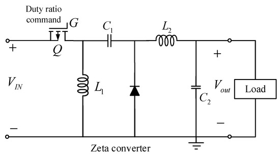
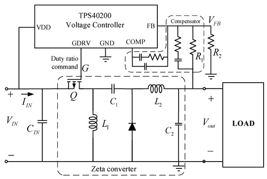
The buck-boost converter considered in this design is a Zeta type converter as shown in Figure 1. A high-speed p-type power MOSFET ( in Figure 1) was employed to control the energy flow and voltage regulation. An example of the TPS40200-based Zeta type buck-boost DC to DC power converter is shown in Figure 2.
Figure 1.
Zeta type buck-boost power converter.
Figure 2.
Voltage regulated Zeta type buck-boost DC to DC power converter.
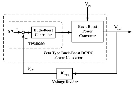
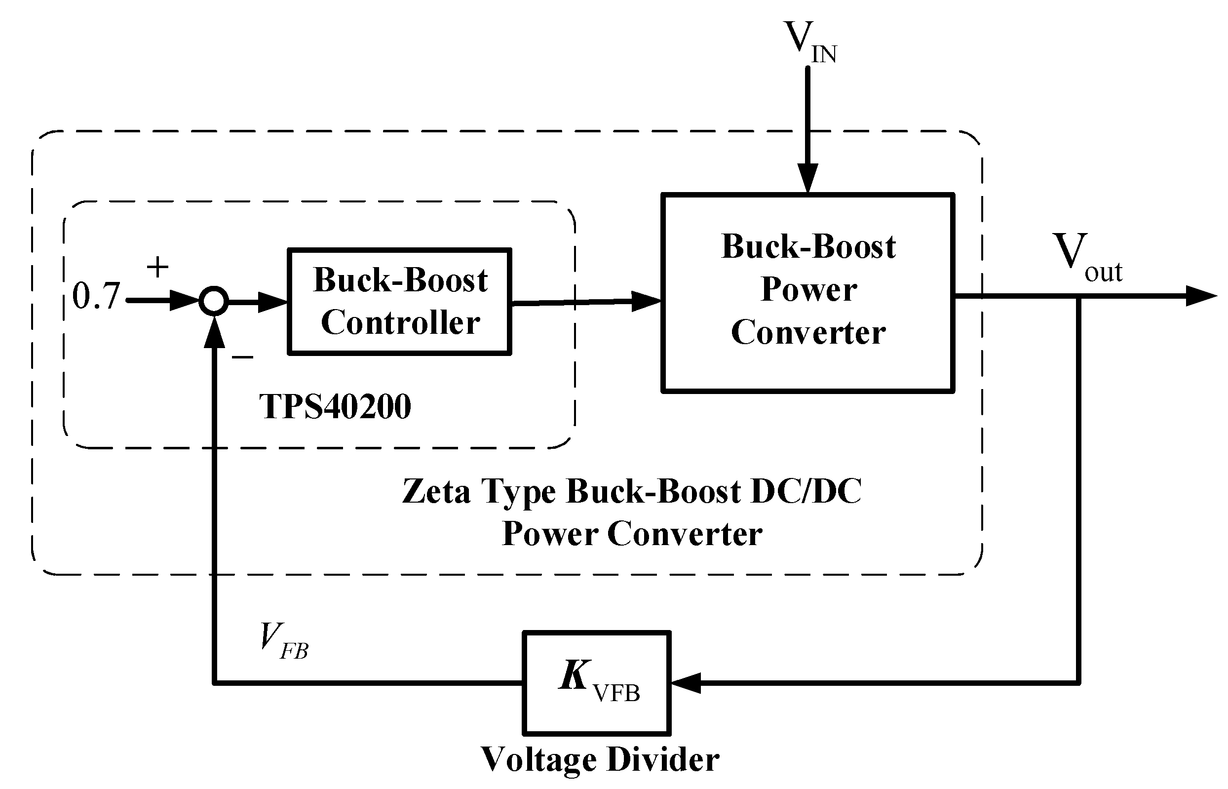
The output voltage in Figure 2 is maintained by regulating the feedback voltage, , of the formed voltage divider as shown in Figure 2. The voltage is regulated at 0.7 V by a feedback control loop in the TPS40200 voltage regulator as depicted in Figure 3. The voltage feedback gain in Figure 3 is a voltage divider formed by . That is
Figure 3.
Feedback control loop of the buck-boost converter.
Thus, the output voltage is maintained at
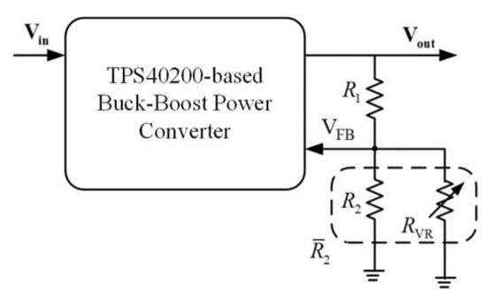
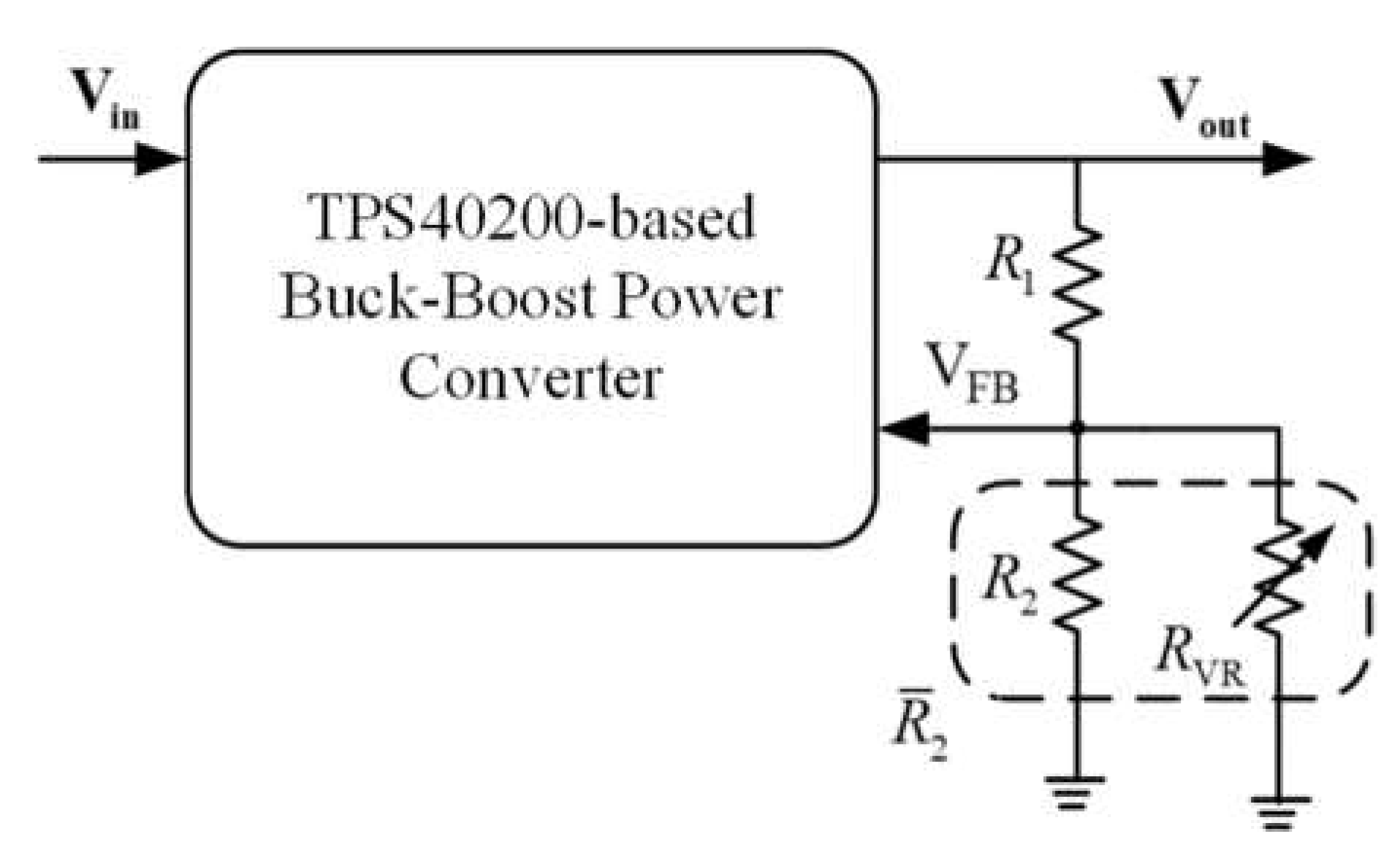
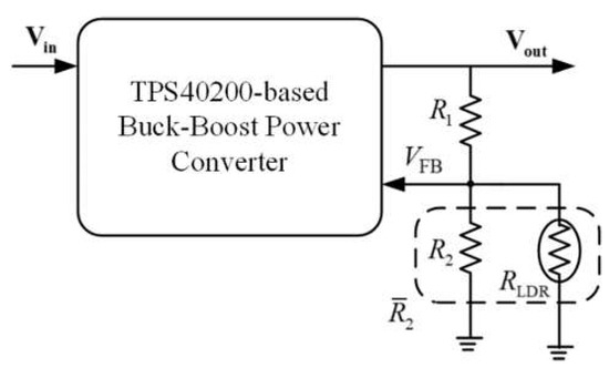
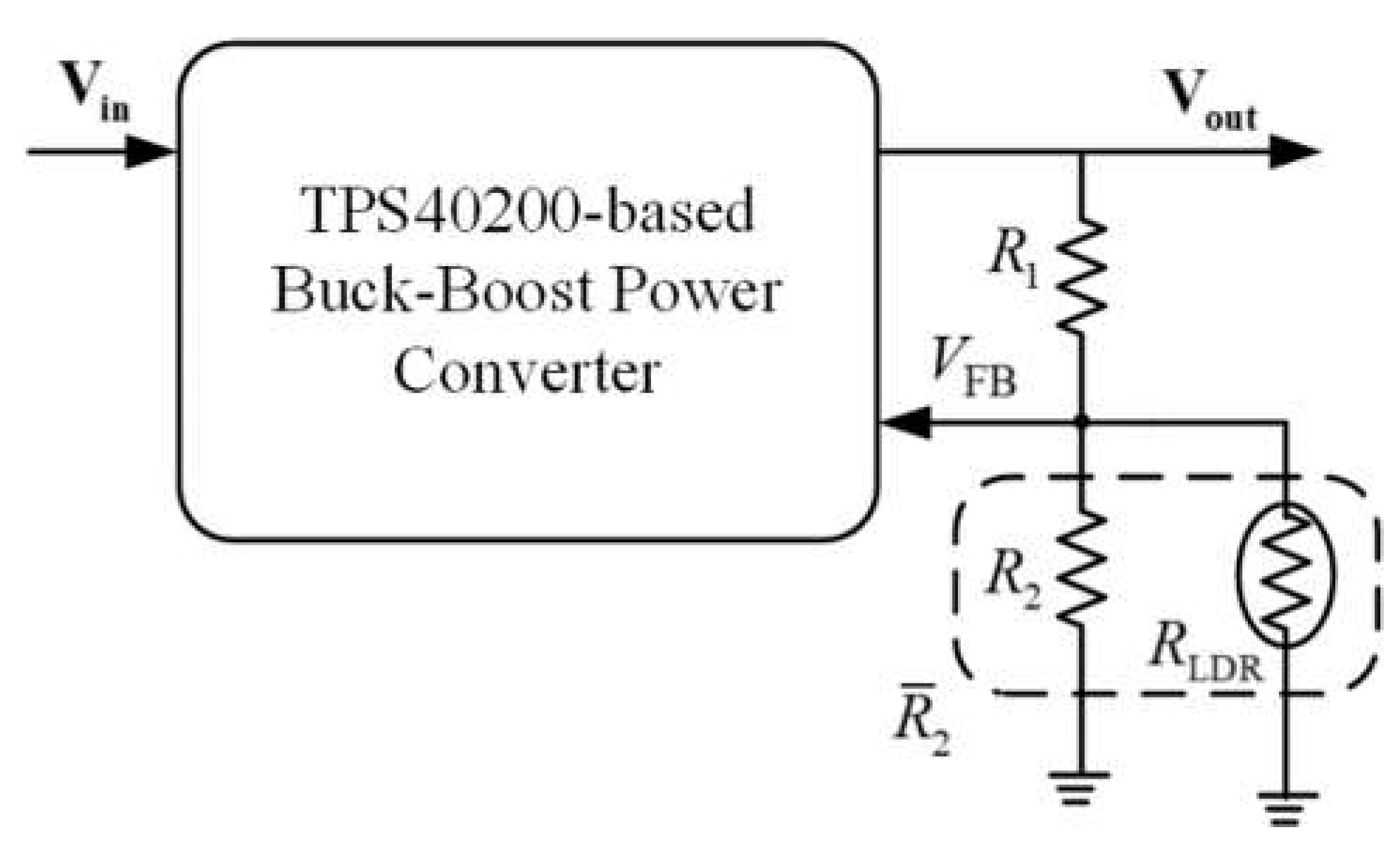
Obviously, output voltage is determined by proper selection of . To simplify the design, we fixed the resistance so that becomes the only variable to control. For example, if we want to control output to vary from +5 V ~ +30 V, we need to control to vary from to if is . The remaining problem becomes how to control the resistance so that the desired is achieved. This implies that must be some form of variable resistor that can be controlled easily. Due to the high-speed switching control of the MOSFETs, a power up problem is inherent in the system if a variable resistor is used directly for . The problem is that we have to set to a proper value before we power up the buck-boost converter otherwise the converter fails to operate or even burns out. To avoid these problems, we used a fixed resistance in parallel with a controlled variable resistor to perform voltage regulation. Two types of variable resistors are discussed in this design as shown in Figure 4 and Figure 5. Figure 4 is the configuration using a digital variable resistor. Figure 5 shows the configuration using a LDR to perform the required function. The drawback of using a digital variable resistor is that it is a contact type resistor with discontinuous changes in the resistance. It creates more unwanted noises in the control process. Furthermore, depending on the resolution of the digital resistor (8 bits and 10 bits are common in the industry) the output voltage is limited to certain steps and easily leads to limit-cycle phenomenon. The LDR based variable resistor provides contactless, continuous changes in its resistance, , according to the light intensity falling on it. Depending on the type and materials used, the resistance can be as low as to when fully illuminated and as high as (dark resistance) when in dark conditions.
Figure 4.
Digital variable resistor based voltage divider.
Figure 5.
Light dependent resistor (LDR) based voltage divider.
From Figure 5, the output voltage is
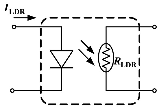
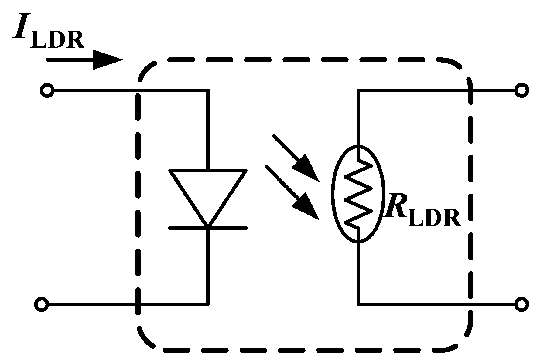
In (3) represents the minimal voltage that appears at the output terminal when the LDR is left uncontrolled (dark resistance). Increasing the light intensity on the LDR decreases the resistance . Thus, the output voltage increases as light intensity on the LDR increases. The LDR and LED integrated device is commercially available [13] for light intensity control of the LDR, as shown in Figure 6. Light intensity is controlled by commanding the current, through the LED, which in turn will change the resistance .
Figure 6.
LED controlled light dependent resistor.
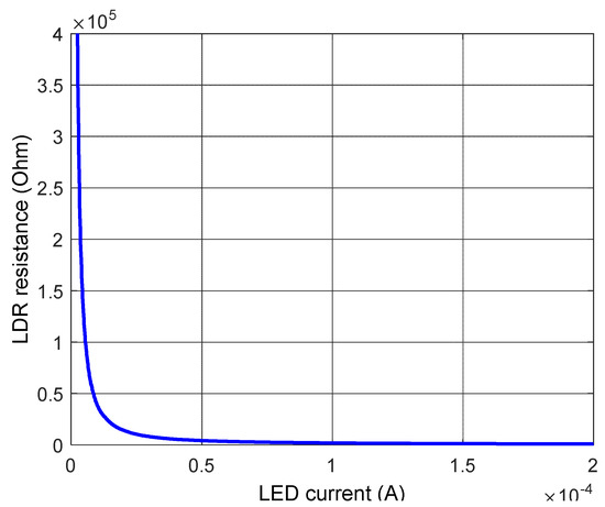
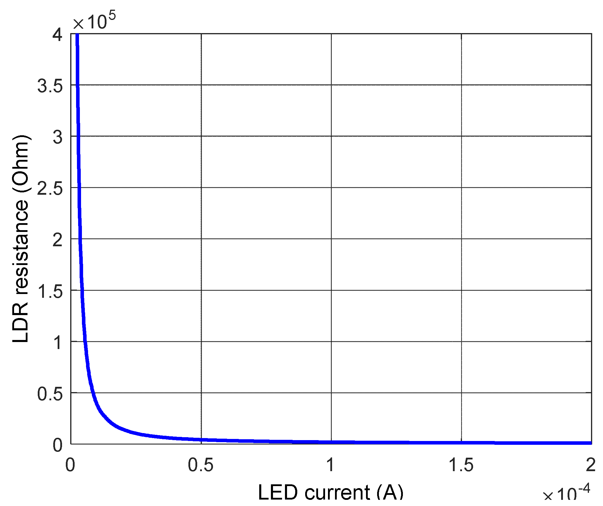
An experiment was conducted to examine the quantitative properties of the LDR. The resistances at different LED currents are shown in Figure 7. It shows the nonlinear phenomenon between the LDR resistance and the applied current. However, the properties might differ slightly from part to part.
Figure 7.
LDR experimental results, versus LED current.
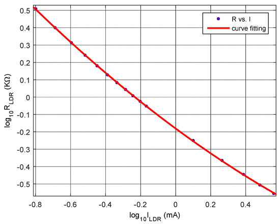
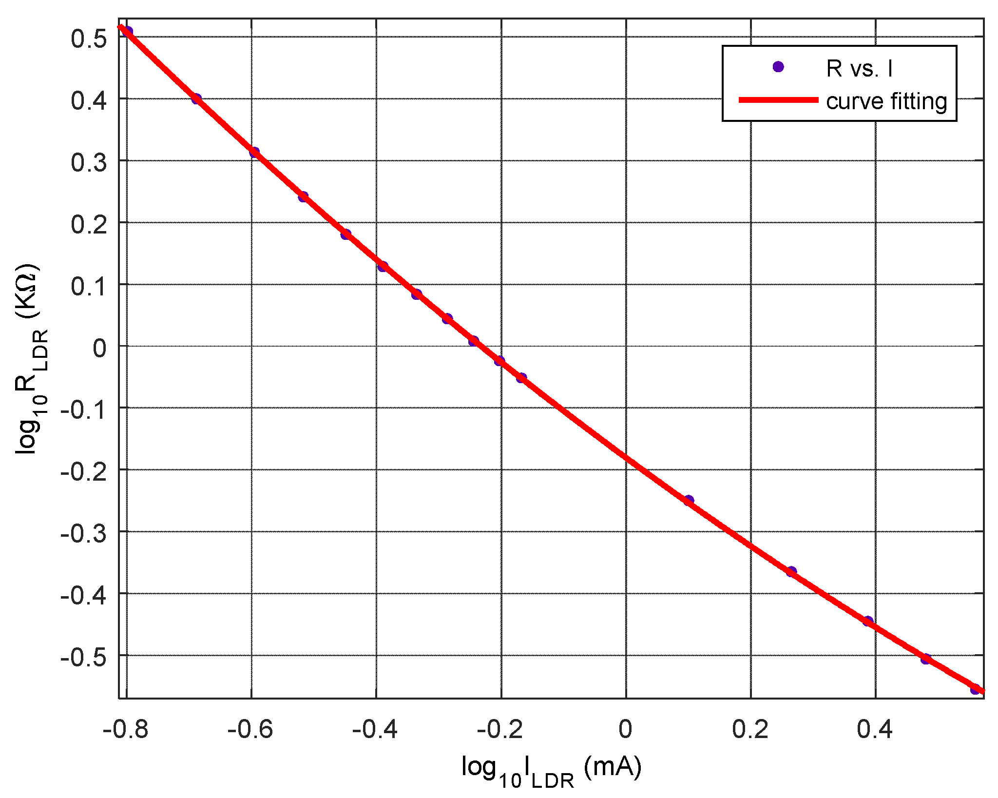
Using curve fitting, the experimental data was expressed by the following
From the characteristics of the LDR, as shown in Figure 7, the sensitivity of with respect to LED current is significant in small current region (high region). Compared to the low resistance region, the contribution to output voltage changes is less significant in the high resistance region. Moreover, control of low LED current is less reliable and impractical. Therefore, a low resistance region was selected for the buck-boost converter design in this study. Figure 8 represents the comparison of test data and curve fitting results for in region. This region is selected in response to the design requirement that is set in this research.
Figure 8.
Comparison of test data and curve fitting results.
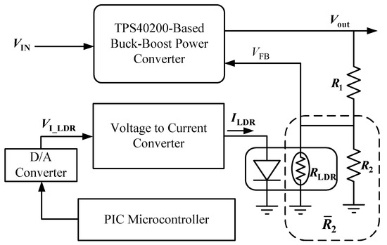
The characteristics of the LDR and its defined control region, the open-loop system of the LDR control, is presented in Figure 9. A voltage to current converter is incorporated in the system to convert the command from the microcontroller to LED demanded current. Figure 2 shows voltage regulation using a Zeta type buck-boost power converter. If the resistors and are fixed, the output voltage will be regulated to a fixed level. Figure 3 represents the voltage regulation in the feedback control loop and can be used for further analysis. Figure 9 shows the schematic diagram for control of the LDR resistance. The output voltage level can then be controlled via control of the LDR resistance.
Figure 9.
Open loop system for LDR control.
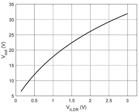
The goal of this research was to design a microcontroller controlled auto-ranging buck-boost power converter for the power management system of an experimental solar-powered UAV. The maximum power point for the PV array used for the UAV was about 24 V at irradiation of 1000 W/m2. For battery charging, the goal was to provide the capability for charging battery modules with either 3 cells or 6 cells connected in series. The charging process includes constant current and constant voltage mechanisms. The required output voltage for 3 cells module is around 10–12.6 V and 20–25.2 V for 6 cells module. The voltage required for the propulsion system is 26 V for the UAV. Conservatively, the range of output voltage was set to be controlled between 5 to 30 V, which covers the design requirements to initiate the design. The resistances , and were selected to achieve . When 1.5 mA LED current is applied to the LDR, the corresponding resistance is which will produce +31.89 V output voltage. The command from the microcontroller was selected to be 0–5 V. The gain for the voltage to current converter was chosen as 2.5/5 (mA/V). The range of we chose for the design was from to . The corresponding LED current was from 0.07 mA to 1.5 mA. Thus, the range of the voltage command was from 0.035 V to 3.0 V. This produces controlled output voltage between , which satisfies the design requirements. The relationship between the output voltage and the command from control unit is shown in Figure 10. Voltages less than 6.49 V are not considered to be as precise as the selected controlled region.
Figure 10.
The relationship between the output voltage and the command from the control unit.
3. Microcontroller Controlled Buck-Boost Power Converter
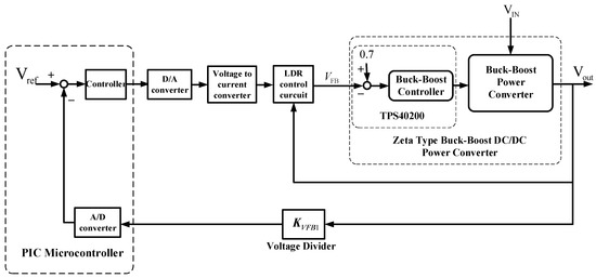
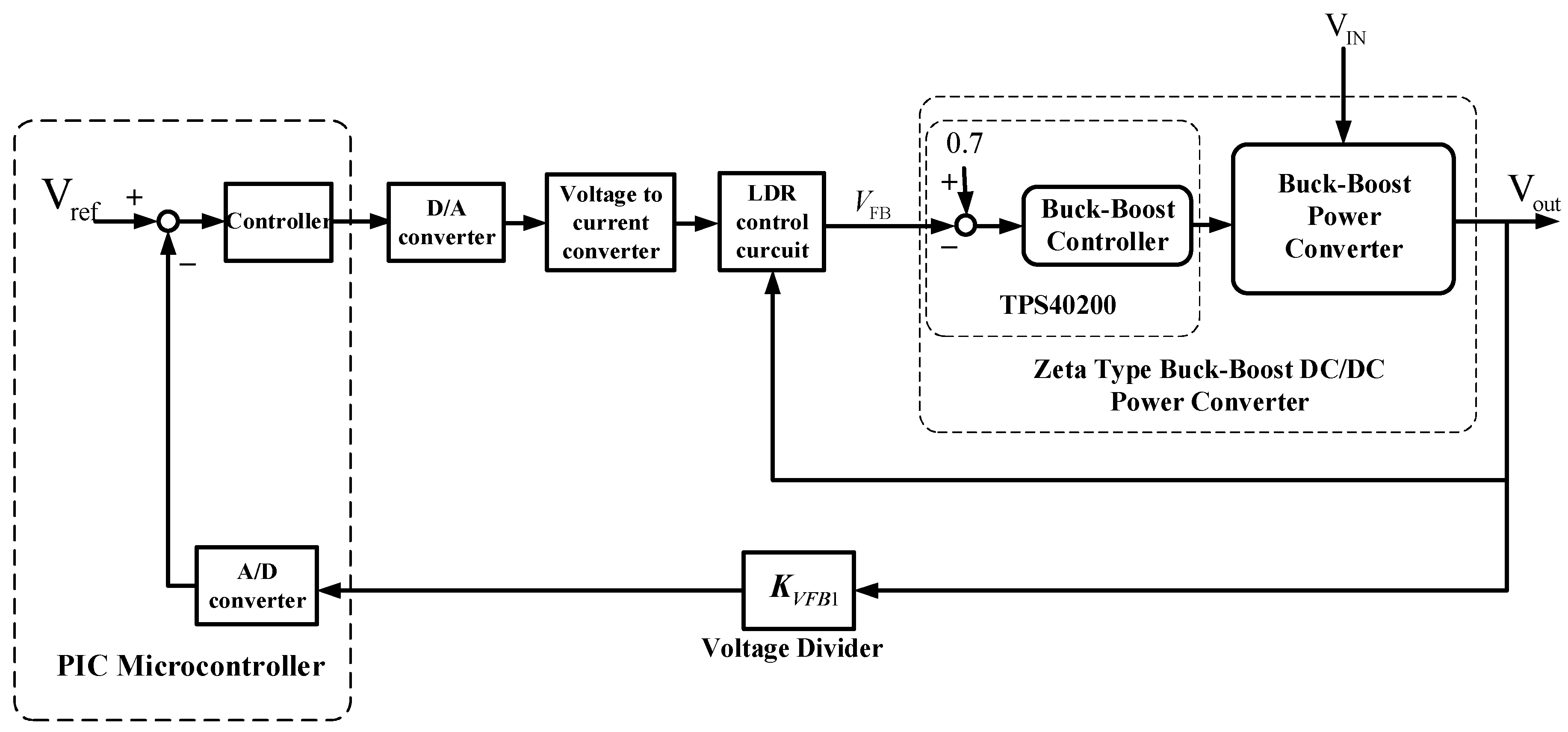
A feedback control system was constructed as shown in Figure 11 to proceed to the control system design. The system contains two control loops. The inner-loop is a voltage regulator based on a Zeta type buck-boost converter. The outer-loop is for the auto-ranging buck-boost power converter. The voltage divider in the outer loop of Figure 11 is used for scaling down the output voltage for the A/D converter. A type III compensator [14] to provide an unconditionally stable loop is employed for the inner-loop. The auto-ranging control loop is accomplished through the control of an LDR installed in between the Zeta converter and the load using a fuzzy-logic based controller.
Figure 11.
Feedback control system of the auto-ranging buck-boost power converter.
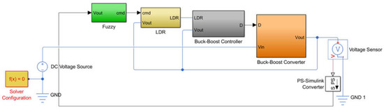
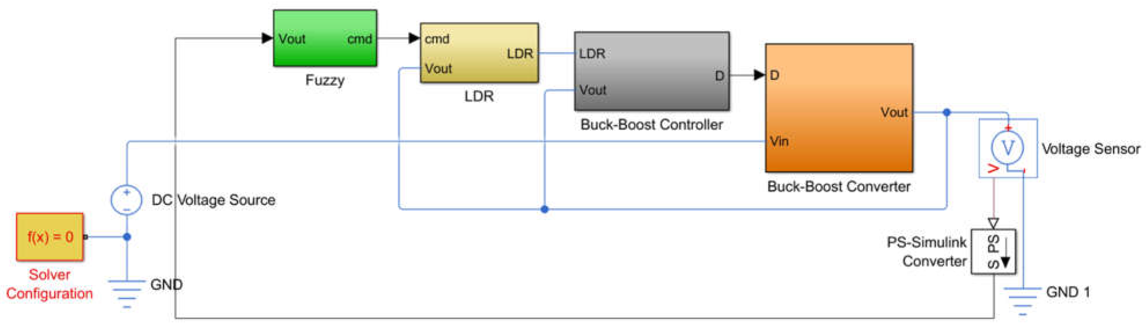
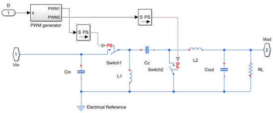
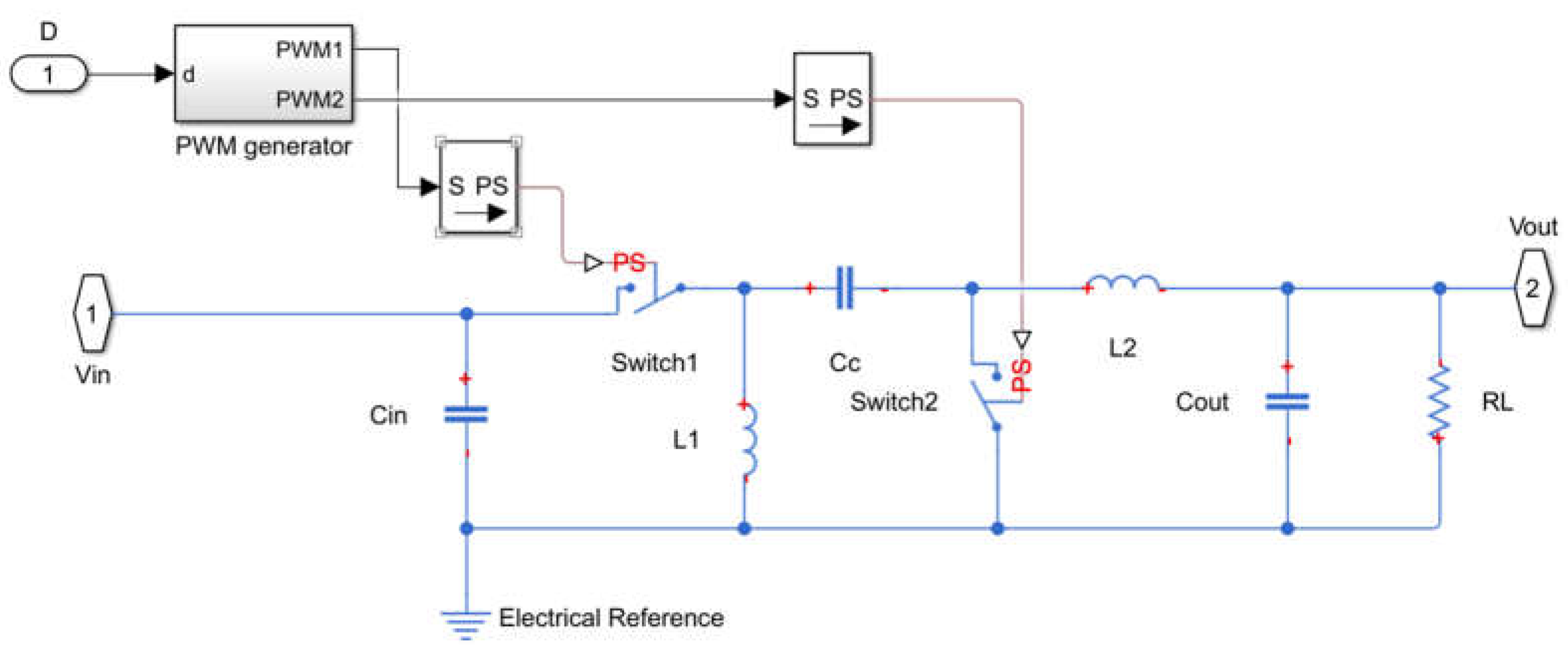
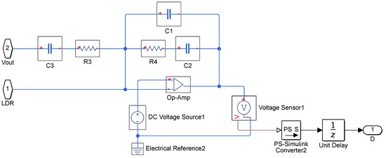
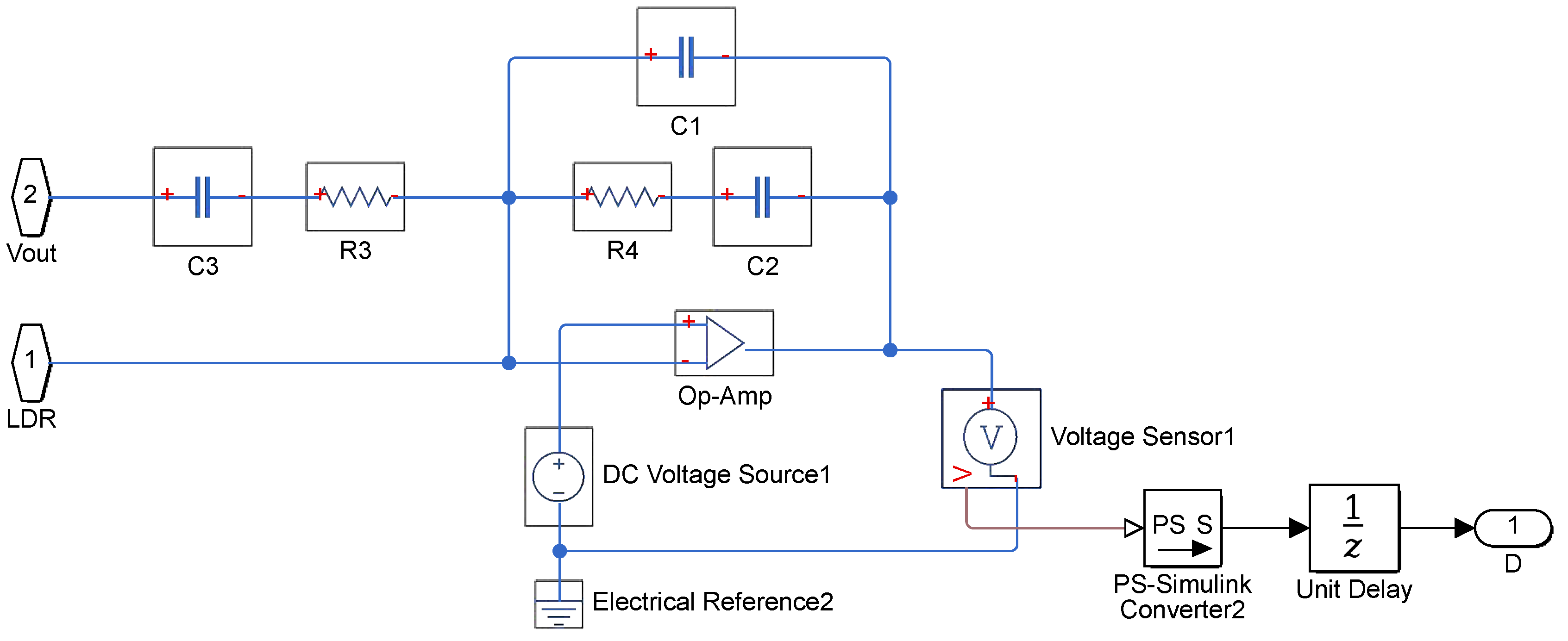
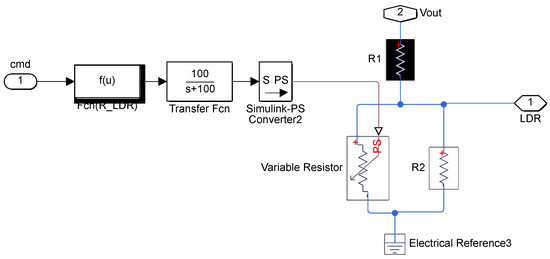
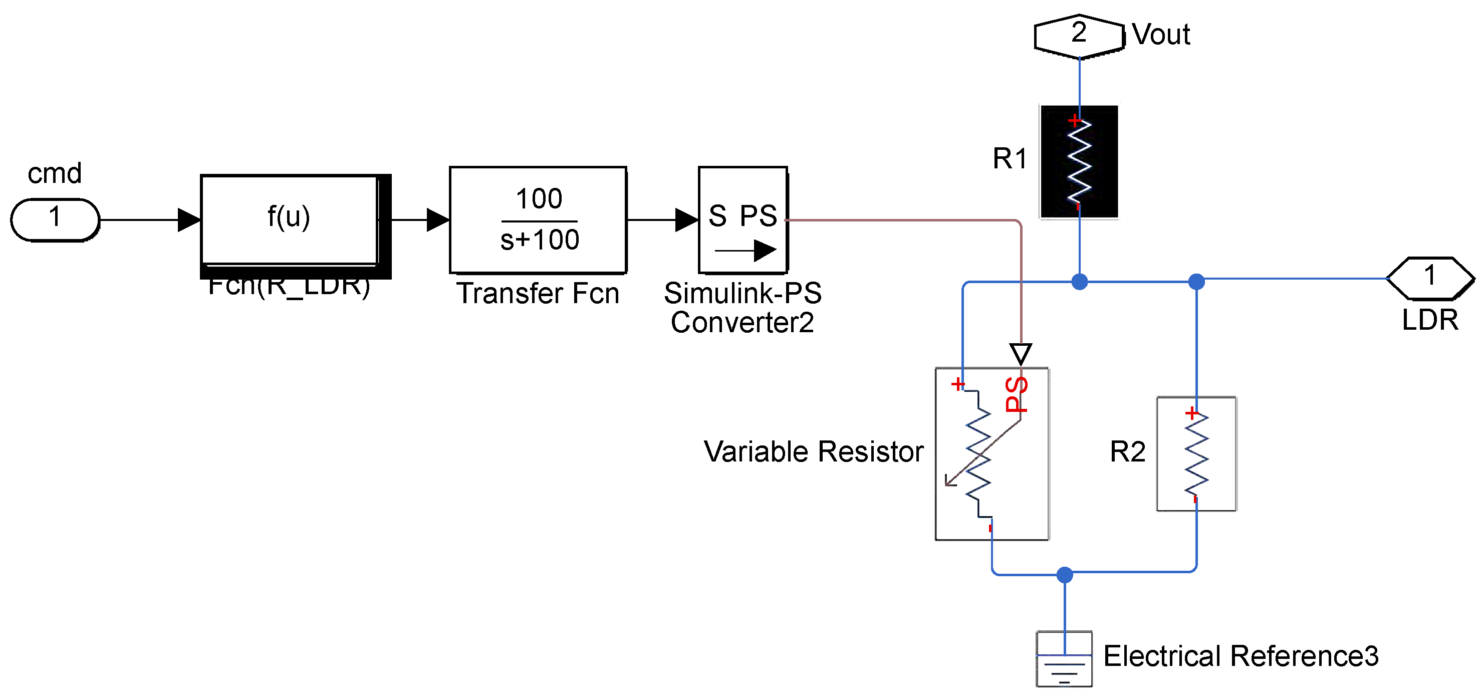
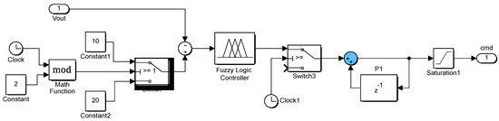
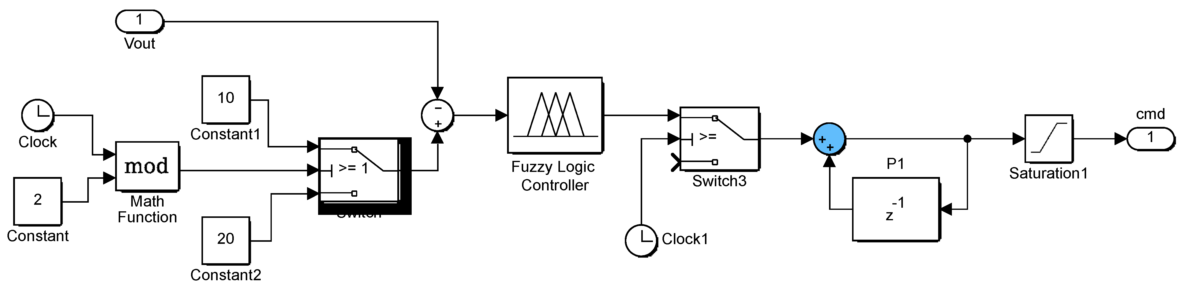
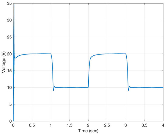
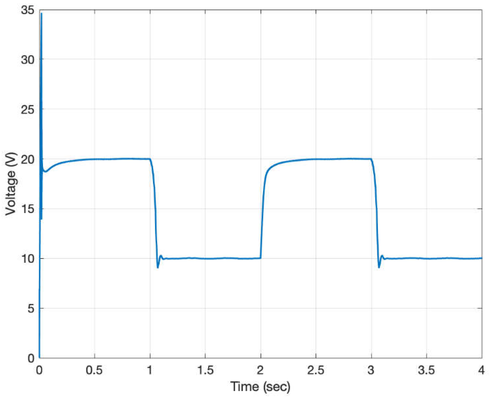
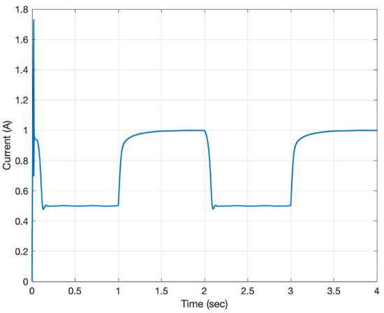
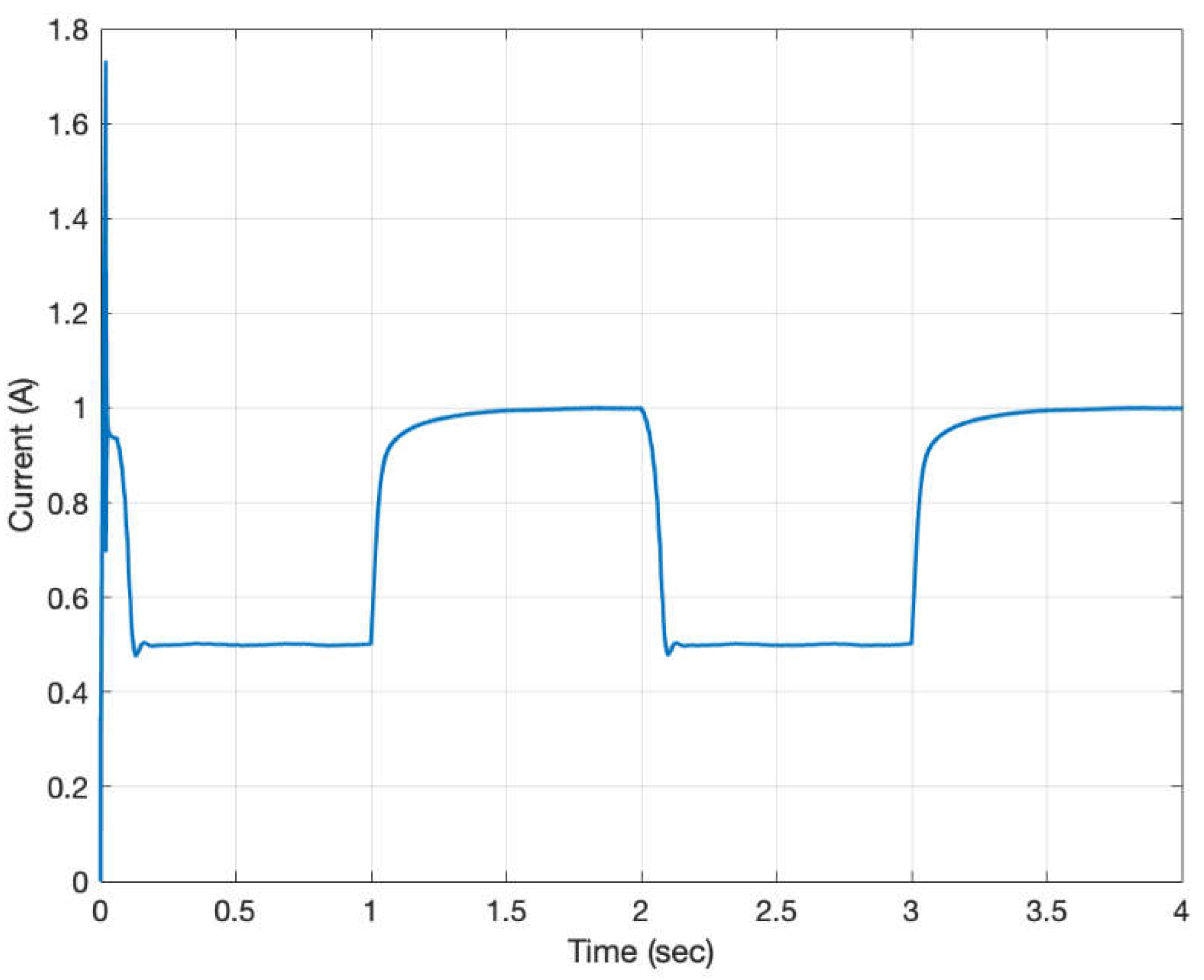
Based on the characteristics of the LDR, the Zeta converter, and the proposed feedback control system, a MATLAB/SIMULINK based circuit simulation model for the auto-ranging DC-to-DC power converting system was developed as shown in Figure 12. The simulation model mainly consists of a Zeta type buck-boost converter model, a Type III compensator based buck-boost controller, an LDR circuit model, and a fuzzy logic controller. Details of the Zeta type buck-boost converter model are shown in Figure 13. The Type III compensator based buck-boost controller for inner-loop voltage regulation is shown in Figure 14. Figure 15 represents the circuit model of the LDR. Figure 16 depicts the fuzzy controller for voltage regulation simulation. Current regulation simulation was carried out in a similar fashion. Results for the voltage regulation simulation are shown in Figure 17. In the simulation the input voltage is 17 V, the output voltage is commanded to provide 20 V for the load for one second, then switched to 10 V for another second. The results clearly indicate the success of voltage regulation. Similarly, results for current regulation are given in Figure 18. In the current regulation simulation, the output current is controlled to deliver 0.5 A to the load for one second, then switched to provide 1 A for another one second. Again, the results demonstrate the success of the design.
Figure 12.
Circuit simulation model of the auto-ranging power converter system.
Figure 13.
Circuit simulation model of the Zeta type buck-boost converter.
Figure 14.
The Type III compensator.
Figure 15.
Circuit simulation model for the LDR.
Figure 16.
Fuzzy controller for voltage regulation simulation.
Figure 17.
Simulation results for voltage regulation.
Figure 18.
Simulation results for current regulation.
4. Practical Applications
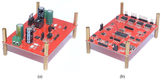
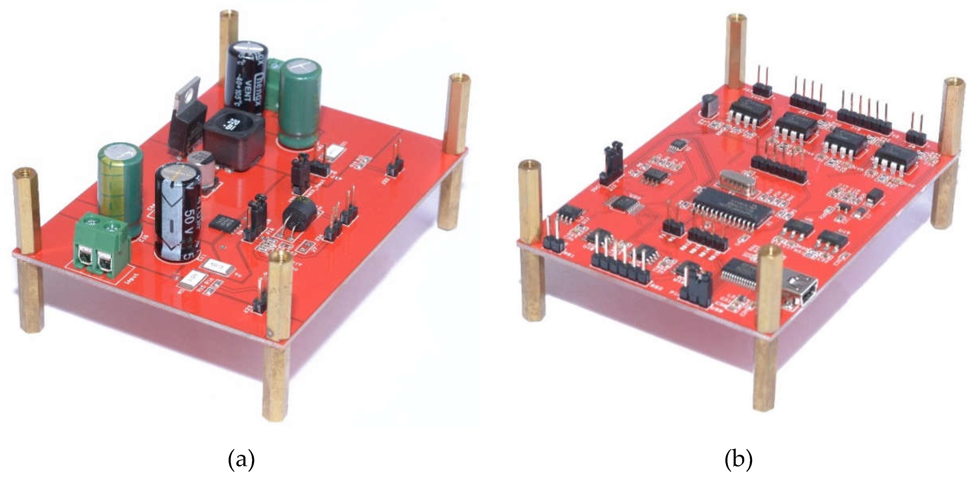
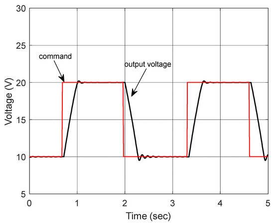
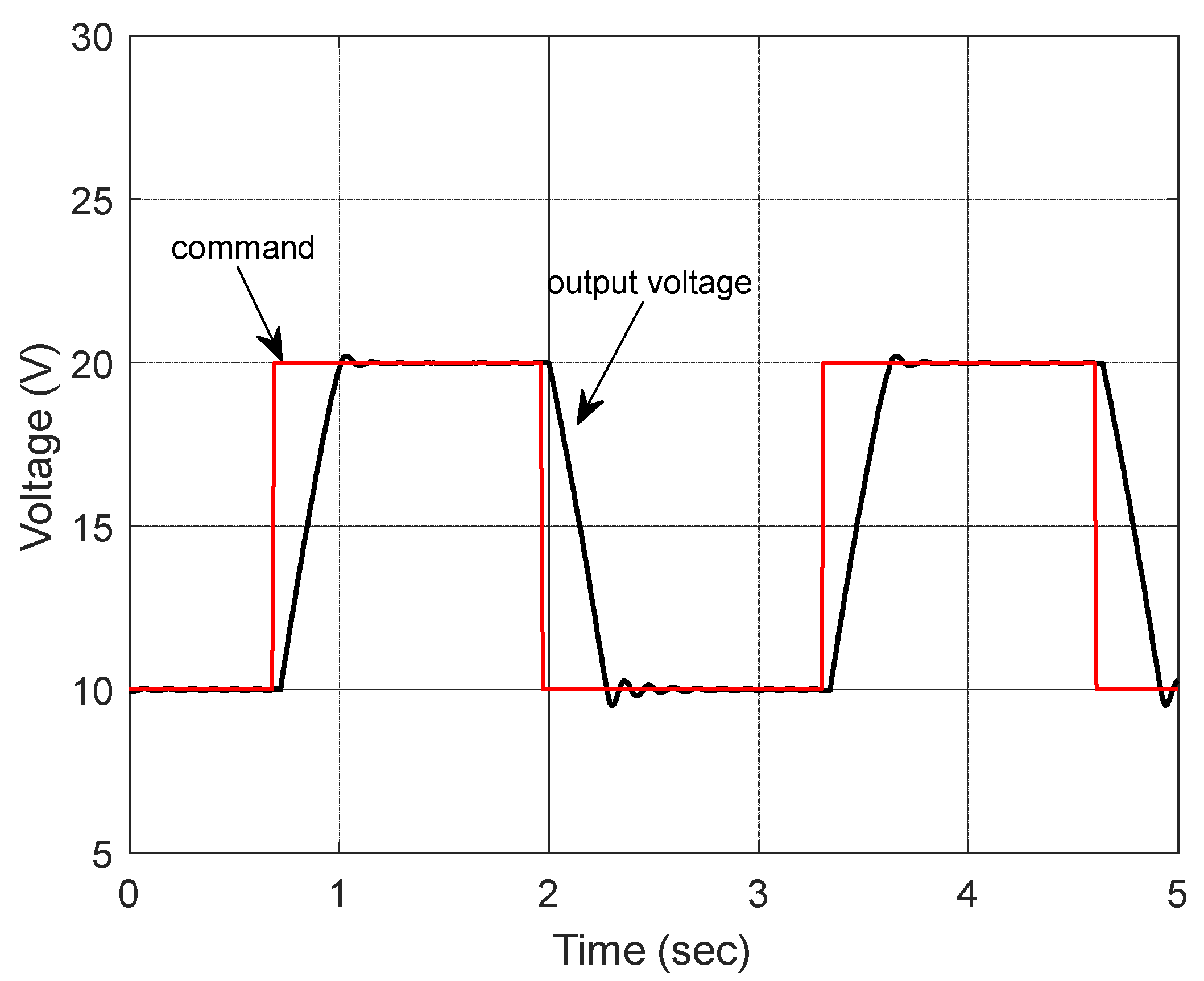
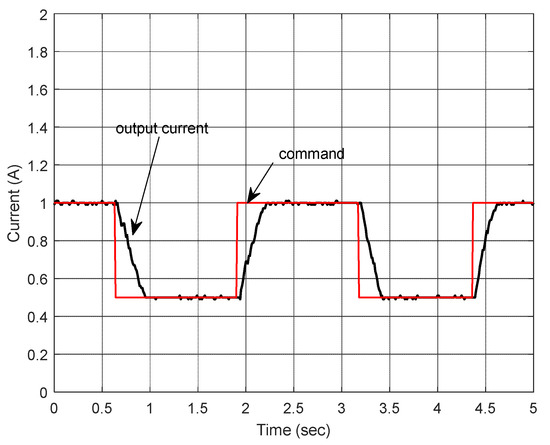
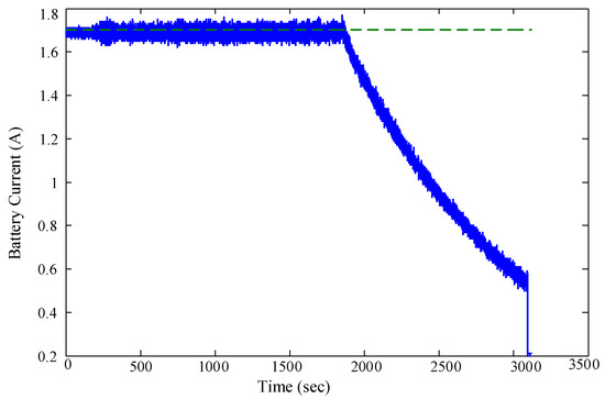
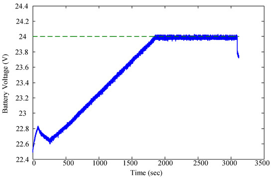
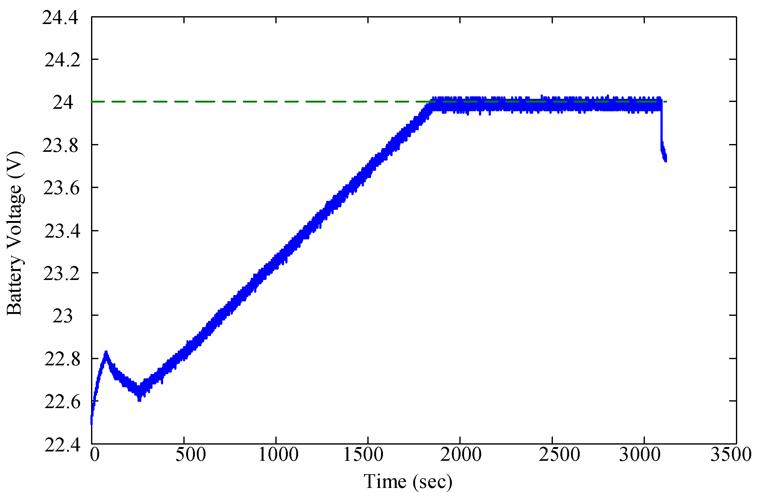
To demonstrate the proposed design, a PIC-microcontroller based auto-ranging buck-boost power converter system was built for a Li-ion battery charging application. Images of the prototype of the system are shown in Figure 19. Before conducting the battery charging test, the voltage and current regulation functions are tested first to verify the design. The results are provide in Figure 20 and Figure 21. The results indicate that the output voltage and current are well regulated to the desired level as expected. Test results for the battery charging are given in Figure 22 and Figure 23. In this test, the converter was set in constant current mode for delivering a constant current of 1.7 A to the battery until the battery voltage reaches 24 V (6 cells connected in series). The system then switches to constant voltage mode, allowing the battery current to taper. The results show the success of Li-ion battery charging using the LDR bridged auto-ranging buck-boost power converter design. It is worth noting that in this study, unidirectional current-sense amplifiers (MAX4080) with sensing resistor were used for current measurement. Overcurrent protection was achieved by using the current limit function provided by the TPS40200 controller. Battery current was software controlled through the current regulation function.
Figure 19.
Auto-ranging power converter: (a) Zeta buck-boost converter, (b) control board.
Figure 20.
Experimental results for voltage regulation.
Figure 21.
Experimental results for current regulation.
Figure 22.
Battery current.
Figure 23.
Battery voltage.
5. Conclusions
The design of an auto-ranging DC-to-DC buck-boost power converter system is presented in this paper. The system contains two control loops: the inner-loop is a Zeta type buck-boost converter and the outer-loop is for voltage and current regulation. The voltage/current regulation was achieved by controlling the resistance of an LDR from the control unit. MATLAB/SIMULINK based circuit simulation models were established and successfully tested. A hardware/software integrated and function tested prototype system was also built in the laboratory. The system was successfully demonstrated for a Li-ion battery charging application. The system can be tailored to other power control applications through minor modification to the software of the control unit. The proposed design method can also be used for buck, boost, or other buck-boost converter topologies.
Author Contributions
Conceptualization and methodology, J.-K.S.; simulation, H.-Y.C.; hardware design and experiments, J.-W.S.; supervision, J.-K.S.; writing, J.-K.S.
Funding
This research received no external funding.
Conflicts of Interest
The authors declare no conflict of interest.
References
- Hsieh, Y.-P.; Chen, J.-F.; Liang, T.-J.; Yang, L.-S. A novel high step-up DC-DC converter for a microgrid system. IEEE Trans. Power Electon. 2011, 25, 1127–1136. [Google Scholar] [CrossRef] [Scilit]
- Shiau, J.; Lee, M.; Wei, Y.; Chen, B. Circuit Simulation for Solar Power Maximum Power Point Tracking with Different Buck-Boost Converter Topologies. Energies 2014, 7, 5027–5046. [Google Scholar] [CrossRef] [Scilit]
- LakshmanRao, S.P.; Kurian, C.P.; Singh, B.K.; Athulya Jyothi, V. Simulation and Control of DC/DC Converter for MPPT Based Hybrid PV/Wind Power System. Int. J. Renew. Energy Res. 2014, 4, 801–809. [Google Scholar]
- Tan, N.M.L.; Abe, T.; Akagi, H. Design and Performance of a Bidirectional Isolated DC–DC Converter for a Battery Energy Storage System. IEEE Trans. Power Electron. 2012, 27, 1237–1248. [Google Scholar] [CrossRef] [Scilit]
- Lin, C.-C.; Yang, L.-S.; Wu, G.W. Study of a non-isolated bidirectional DC_DC converter. IET Power Electron. 2012, 6, 30–37. [Google Scholar] [CrossRef] [Scilit]
- Son, H.-S.; Kim, J.K.; Lee, J.-B.; Moon, S.-S.; Park, J.-H.; Lee, S.-H. A new buck-boost converter with low voltage stress and reduced conducting components. IEEE Trans. Ind. Electon. 2017, 64, 7030–7038. [Google Scholar] [CrossRef] [Scilit]
- Moon, B.; Jung, H.Y.; Kim, S.H.; Lee, S. A Modified Topology of Two-Switch Buck-Boost Converter. IEEE Access 2017, 5, 17772–17780. [Google Scholar] [CrossRef] [Scilit]
- Linear Technology Corporation. LTC3780 High Efficiency, Synchronous, 4-Switch Buck-Boost Controller; Linear Technology Corporation: Milpitas, CA, USA, 2005. [Google Scholar]
- Texas Instruments. TPS40200 Wide Input Range Non-Synchronous Voltage Mode Controller; Texas Instruments: Dallas, TX, USA, 2014. [Google Scholar]
- Texas Instruments. TPS4005x Wide-Input Synchronous Buck Controller; Texas Instruments: Dallas, TX, USA, 2014. [Google Scholar]
- Maranhão, G.N.D.A.; Brito, A.U.; Leal, A.M.; Fonseca, J.K.S.; Macêdo, W.N. Using LDR as Sensing Element for an External Fuzzy Controller Applied in Photovoltaic Pumping Systems with Variable-Speed Drives. Sensors 2015, 15, 24445–24457. [Google Scholar] [CrossRef] [Scilit] [PubMed]
- Gouthami, C.; Santosh, A.; Pavan Kumar, A.; Karthik, A.; Ramya, K.R. Design and Implementation of Automatic Street Light Control System using Light Dependent Resistor. Int. J. Eng. Trends Technol. 2016, 35, 465–470. [Google Scholar]
- Luna Optoelectronics. Optocoupler NSL-SR2 (Sorted); Luna Optoelectronics: Camarillo, CA, USA, 2016. [Google Scholar]
- Cao, L. Type III Compensator Design for Power Converters. Power Electron. Technol. 2011, 37, 20–25. [Google Scholar]
© 2018 by the authors. Licensee MDPI, Basel, Switzerland. This article is an open access article distributed under the terms and conditions of the Creative Commons Attribution (CC BY) license (http://creativecommons.org/licenses/by/4.0/).