


Abstract
This paper proposes improving the dynamic characteristics of a personal mobility device (PMD) battery charger using fuzzy logic control (FLC). Recently, as the use of PMD has expanded, research on the PMD battery charger has also been actively conducted. To control the output voltage of the PMD battery charger, a simple proportional–integral (PI) controller is mainly used. However, increasing the gains of the PI controller to improve the dynamic characteristics of the PMD battery charger can cause overshoot, oscillations, and sensitivity to disturbances. To overcome these limitations, this paper proposes an FLC-based output voltage control of the PMD battery charger. The proposed control method determined the reference inductor current using the membership functions and output intensity. In addition, the proposed control method exhibits improved dynamic characteristics compared to PI-based output voltage control in the transient state, reducing the settling time by approximately 55.26% and reaching a steady state stably without overshoot. The validity of the proposed FLC-based output voltage control method was verified through simulation and experimental results.
1. Introduction
Recently, as interest in sustainable, eco-friendly transportation has increased, the spread and use of personal mobility devices (PMDs) that use electricity as a power source have expanded rapidly [1,2,3,4]. PMD is intended for low-speed and short-distance transportation and generally includes electric scooters, electric wheelchairs, electric bicycles, and electric motorcycles. PMD has been widely adopted for personal transportation due to its portability, convenience, and ease of access. However, despite these advantages, a limitation remains in that the required battery voltage range varies among device types. For example, the battery voltage used for electric scooters and electric wheelchairs is 24 V–36 V, the battery voltage used for electric bicycles is 24 V–48 V, and the battery voltage used for electric motorcycles is 72 V [5,6]. Accordingly, users who own various types of PMD need to have many battery chargers due to the variety of battery voltages used by battery chargers. To solve these limitations, research on PMD battery chargers with various output voltages is actively conducted [7,8,9,10].
The simplest structure of a PMD battery charger with a wide output voltage range is a one-stage battery charger using a single-ended primary-inductor converter (SEPIC). However, since the SEPIC is basically a non-isolated structure, it is difficult to ensure stability. A two-stage battery charger typically comprises a power factor correction (PFC) boost converter and an LLC resonant converter. These chargers can minimize current ripple and improve battery lifespan. However, the output voltage control method based on frequency modulation is complex, and maintaining stable control over a wide voltage range is challenging. Conventional single-stage and two-stage battery chargers have limitations such as difficulty in magnetic component design and complicated control structures. To overcome these limitations, this paper employs a three-stage battery charger with improved design flexibility and a wide output voltage range.
Generally, the proportional–integral (PI) controller is used to control the output voltage and inductor current of PMD battery chargers. The PI controller has been widely used in power electronic systems due to its simple structure and ease of implementation. However, the PI controller employs fixed gains regardless of the output voltage error, making it difficult to adapt the control performance to varying operating conditions. In addition, increasing the gains to improve dynamic performance may cause overshoot, oscillation, and sensitivity to disturbances [11,12,13,14,15]. Accordingly, the need for a method to stably and efficiently control the output voltage is also emerging [16]. To address these limitations, research using a fuzzy logic control (FLC) method is actively conducted in the field of power electronics. The FLC method utilizes a rule-based structure inspired by human reasoning and expresses control rules linguistically with vague boundaries. Moreover, it can respond flexibly to various voltage ranges [17,18,19,20,21].
Therefore, this paper proposes improving the dynamic characteristics of the PMD battery charger using FLC. The proposed FLC-based output voltage control method determined the reference inductor current using the membership functions and output intensity according to the output voltage error. Moreover, when the output voltage error is large, the reference inductor current is increased to enhance responsiveness. Whereas when the output voltage error is small, the reference inductor current is decreased to reduce overshoot. For these reasons, the proposed control method exhibits improved dynamic characteristics compared to PI-based output voltage control in the transient state, reducing the settling time and reaching a steady state stably without overshoot. Consequently, the proposed charger structure and control method can improve the dynamic performance and operating flexibility of the battery charger. In this paper, the structure of the PMD battery charger, the PI-based output voltage control method, and the proposed FLC-based output voltage control method are explained, and the validity of the proposed control method is verified through simulation and experimental results.
2. Structure and Control Method of PMD Battery Charger
2.1. Structure of PMD Battery Charger
The structure of the PMD battery charger employs various configurations, including single-stage, two-stage, and three-stage topologies. The simplest configuration, the single-stage battery charger, uses a SEPIC, while the two-stage battery charger uses a PFC boost converter and LLC resonant converter or a SEPIC. In the single-stage battery charger, designing the magnetic components is difficult. Moreover, the SEPIC is electrically non-isolated, which can also lead to stability problems. In a two-stage battery charger, the output voltage is regulated by an LLC resonant converter. In this case, output voltage control using frequency modulation is complex, and stable control performance over a wide output voltage range is limited. Therefore, this paper employed a three-stage battery charger, which offers circuit design flexibility over single-stage and two-stage battery chargers.
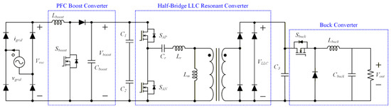
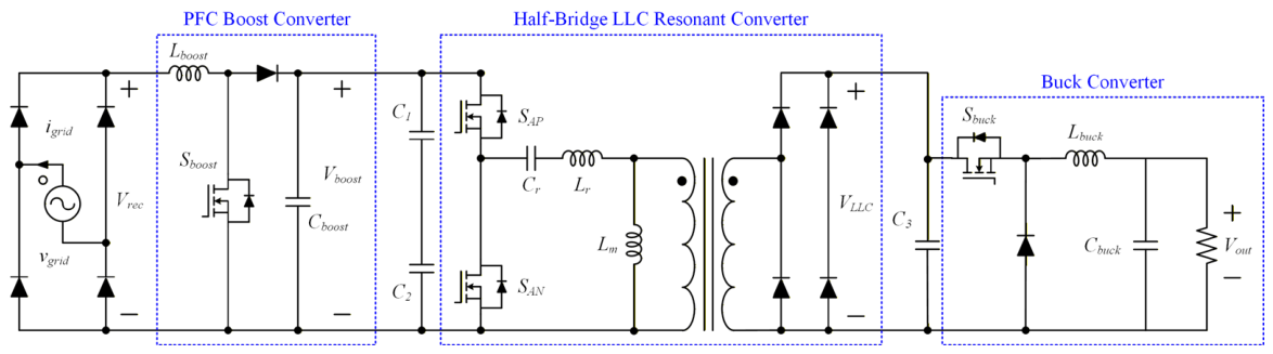
Figure 1 shows the structure of the PMD battery charger, which consists of a PFC boost converter, a half-bridge LLC resonant converter, and a buck converter. The output voltage range of the three-stage PMD battery charger was set from 24 V to 72 V, considering the standard operating voltage specifications of most commercial PMD batteries. Compared to PMD battery chargers with single-stage or two-stage structures, the number of switches and passive components is slightly higher. However, the volume of the PMD battery charger does not increase significantly, and does not affect the portability.
Figure 1.
Structure of the PMD battery charger.
The input-side single-phase grid voltage is rectified to DC through a diode-bridge rectifier and boosted to 400 V by a PFC boost converter. When an inductive load is employed, reactive power may be generated during the energy storage and release process of the inductor, and the power factor may be reduced. Accordingly, the input power factor of the single-phase grid is controlled to be maintained at unity power factor by employing a PFC boost converter. A DC voltage boosted by the PFC boost converter is converted into an AC voltage by alternately driving the half-bridge switch SAP and a SAN at a duty ratio of 0.5. The converted AC voltage is isolated by the transformer, scaled by the turn ratio, and rectified to a DC voltage. Finally, the rectified DC voltage can be controlled to various output voltages through the buck converter.
In the PFC boost converter and buck converter, the inductor smooths the current to reduce the current ripple, and the capacitor maintains a stable output voltage to reduce the output voltage ripple. These components were designed by considering the switching frequency, maximum output current, and allowable output current and voltage ripples. In the half-bridge LLC resonant converter, the resonant inductor (Lr), resonant capacitor (Cr), and magnetizing inductance (Lm) provide a stable output voltage under load variations. These components were designed by considering the input and output voltage ranges, load conditions, resonant frequency, and ripple requirements. In addition, two capacitors (C1, C2) were used to stabilize the upper and lower input-side voltages, and they were designed by considering the reduction in voltage ripple.
2.2. Operation Principle of PMD Battery Charger
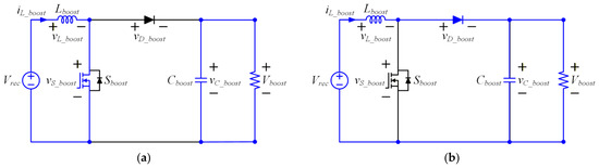
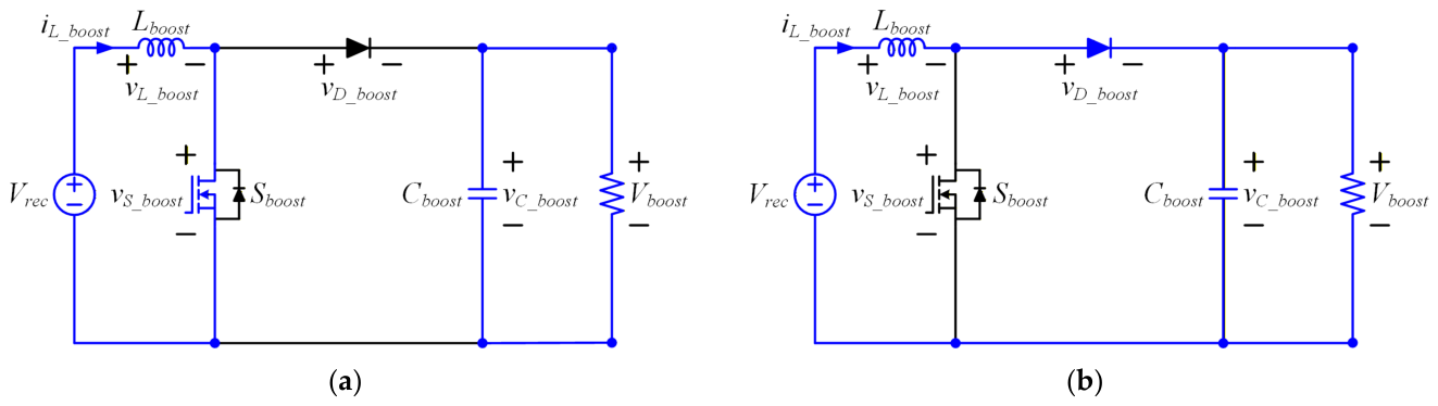
Figure 2 shows the equivalent circuit of the boost converter. Mode 1 represents the state when the boost converter switch (Sboost) is ON, and Mode 2 represents the state when the Sboost is OFF.
Figure 2.
Equivalent circuit of the boost converter: (a) Mode 1 and (b) Mode 2.
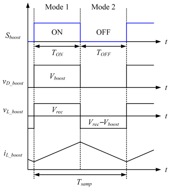
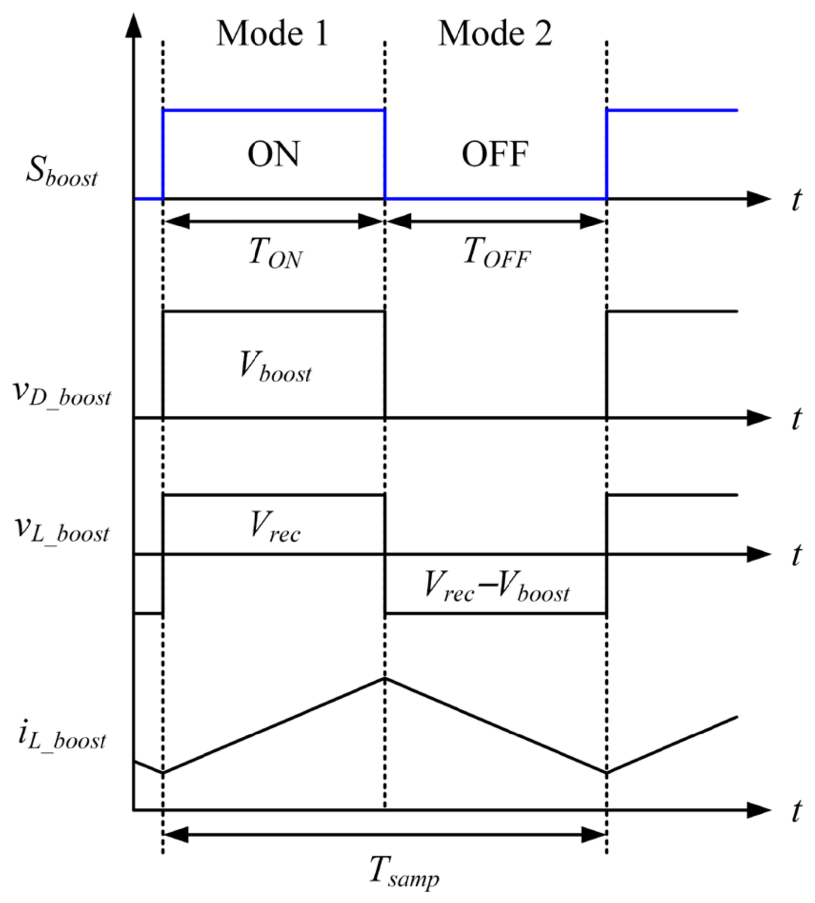
In Mode 1, the diode in the boost converter is OFF, and the voltage of the diode (vD_boost) is equal to the output voltage (Vboost). In addition, since the inductor voltage (vL_boost) is equal to the input voltage (Vrec), the positive vL_boost causes the inductor current (iL_boost) to increase. In Mode 2, the diode is ON, and the switch voltage (vs_boost) is equal to Vboost. vL_boost is the difference between Vrec and Vboost, resulting in a negative voltage across the inductor and causing iL_boost to decrease.
Figure 3 shows the voltage and current waveforms depending on the switching state of the boost converter. The switching operation controls the output voltage of the boost converter.
Figure 3.
Voltage and current waveforms depending on the switching state of the boost converter.
The average of the inductor voltage (VL_boost) is determined by Vrec and Vboost, and VL_boost is calculated as in (1).
where Dboost is the duty ratio of Sboost and Tsamp is the control period. In the steady state, the average value of VL_boost becomes zero due to the flux balance condition. Accordingly, the voltage transfer ratio (GV) is calculated as in (2).
The state of Sboost changes from ON to OFF during the Tsamp. The switch ON time (TON) and switch OFF time (TOFF) of Sboost are expressed as in (3).
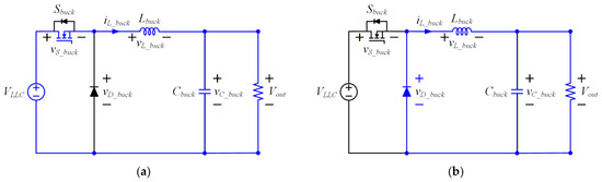
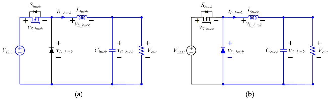
Figure 4 shows the equivalent circuit of the buck converter. Mode 1 represents the state when the buck converter switch (Sbuck) is ON, and Mode 2 represents the state when the Sbuck is OFF.
Figure 4.
Equivalent circuit of the buck converter: (a) Mode 1 and (b) Mode 2.
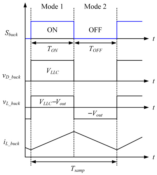
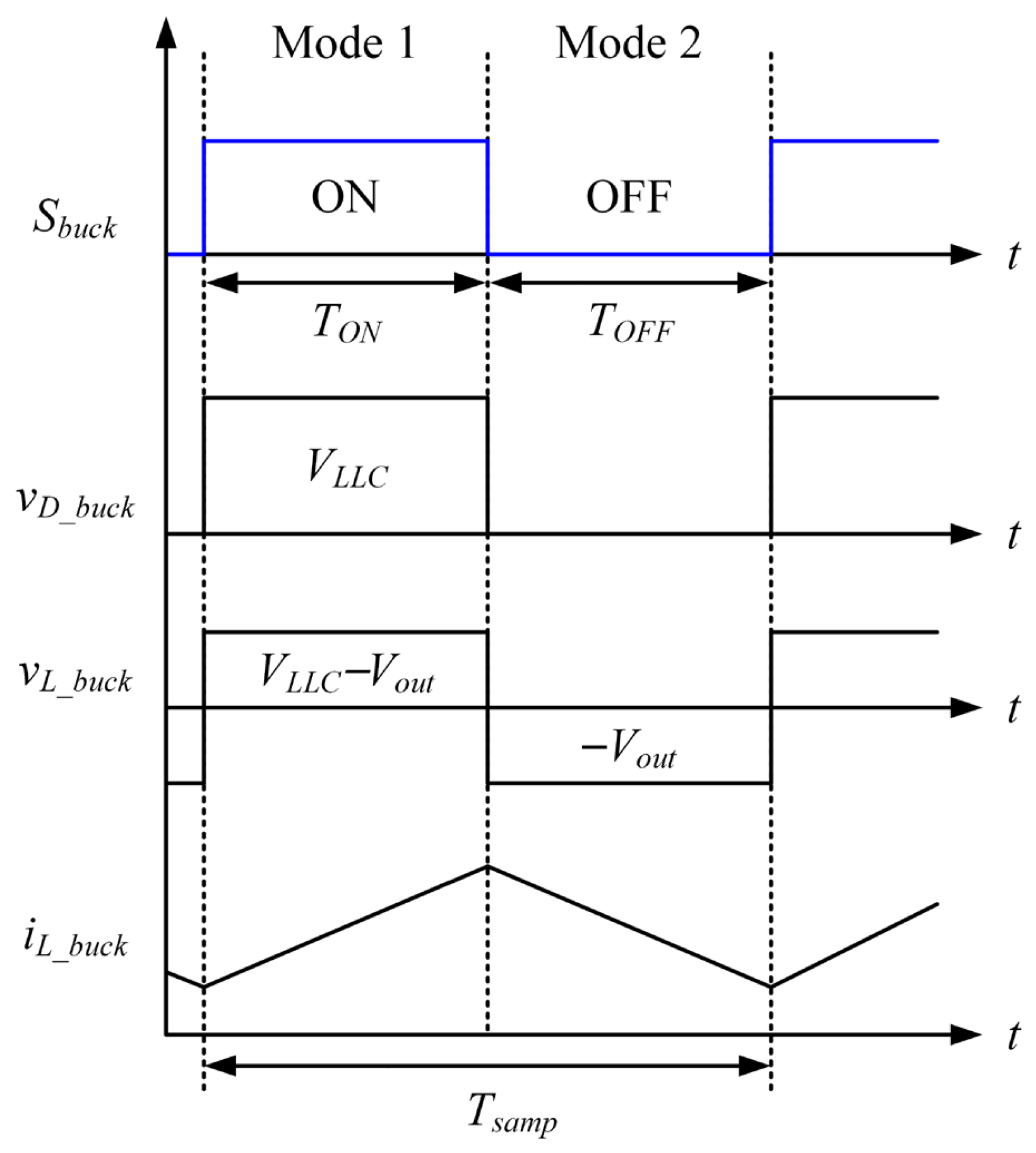
In Mode 1, the diode in the buck converter is OFF, and the voltage of the diode (vD_buck) is equal to the input voltage (VLLC). In addition, since the inductor voltage (vL_buck) is the difference between VLLC and the output voltage (Vout), the positive vL_buck cause the inductor current (iL_buck) to increase. In Mode 2, the diode is ON, and the switch voltage (vs_buck) is equal to VLLC. vL_buck becomes −Vout, resulting in a negative voltage across the inductor and causing iL_buck to decrease.
Figure 5 shows the voltage and current waveforms depending on the switching state of the buck converter. The switching operation controls the output voltage of the buck converter.
Figure 5.
Voltage and current waveforms depending on the switching state of the buck converter.
The average value of the inductor voltage (VL_buck) is determined by VLLC and Vout, and VL_buck is calculated as in (4).
where Dbuck is the duty ratio of Sbuck. In the steady state, the average of VL_buck becomes zero due to the flux balance condition. Accordingly, the GV is calculated as in (5).
The switching state of Sbuck changes from ON to OFF during the Tsamp. The TON and TOFF are expressed in (6).
2.3. Conventional PI-Based Output Voltage Control Method
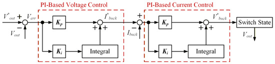
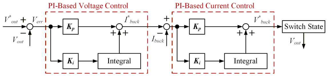
Figure 6 shows the control block diagram of the PI-based output voltage control method. The PI control method, which has a simple structure and ease of implementation, is widely used to control the output voltage of the PMD battery charger.
Figure 6.
Control block diagram of PI-based output voltage control method.
The control variable used as the input of the PI controller (Verr) is defined as the difference between V*out and Vout, as in (7).
The PI-based output voltage control method consists of a proportional controller and an integral controller. The proportional controller mainly determines the responsiveness, whereas the integral controller mainly affects the steady state error. This characteristic is influenced by the proportional gain (Kp) and integral gain (Ki). In the PI-Based voltage control and current control loops, Kp and Ki are given as in (8) and (9), respectively.
where ωvc represents the voltage control bandwidth, ωcc represents the current control bandwidth, and Cbuck and Lbuck represent the capacitance and inductance of the output buck converter, respectively. The reference inductor current (I*buck) used as the output of the PI-based output voltage control method is calculated as in (10).
Similarly, the error between I*buck and inductor current (Ibuck) is used as the input to the PI-based current control, and the switch state is determined from the reference voltage of the buck converter (V*buck).
Consequently, the performance of the controller is determined by the proportional and integral gains. Increasing proportional gains for fast responsiveness may result in overshooting. Decreasing proportional gain degrades the dynamic characteristic, and the ability to cope with disturbances decreases. Increasing integral gain can result in system instability, response delays, and oscillations due to accumulated errors. Decreasing the integral gain results in a steady state error, which reduces responsiveness. Therefore, the controller performance of the PI controller is determined by the gain, and the controller gain tuning process is difficult. These limitations make it difficult to improve the dynamic characteristics of the PMD battery charger.
3. The Proposed FLC-Based Output Voltage Control Method
Conventional binary logic used in computers has only two truth values: true and false. In contrast, fuzzy logic can represent intermediate truth values with ambiguous boundaries. Based on this principle, the FLC method expresses control rules in linguistic form and performs the three-stage control process of fuzzification, fuzzy inference, and defuzzification.
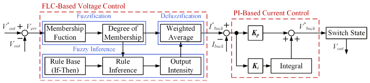
Figure 7 shows a control block diagram of the FLC-based output voltage controller. The proposed FLC-based output voltage control method uses Verr as input, as in (7). Subsequently, through the processes of fuzzification, fuzzy inference, and defuzzification, it controls the Vout to the V*out and outputs I*buck. Using the I*buck, it performs PI-based current control and outputs V*buck. Finally, after normalizing V*buck, the switching state of the buck converter is determined by comparing it with the triangular wave, controlling the output voltage of the buck converter.
Figure 7.
Control block diagram of the FLC-based output voltage controller.
3.1. Fuzzification
Fuzzification is the process of converting the crisp value used as the controller input into a fuzzy value. In the definition of membership functions and degree of membership (DOM), trapezoidal and triangular shapes are commonly employed for computational efficiency and ease of implementation. The performance of the FLC using trapezoidal and triangular membership functions is similar, and in this paper, the triangular membership functions were adopted for ease of implementation.
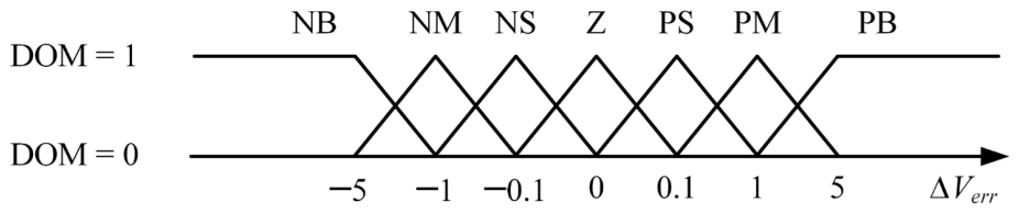
Figure 8 shows the membership functions and degree of membership, and Table 1 shows the definition of membership functions.
Figure 8.
Membership functions and degree of membership.
Table 1.
Definition of membership functions.
To ensure the performance of the FLC, the number of membership functions must be set appropriately. Increasing the number of membership functions for improved control performance may result in a higher computational burden. Decreasing the number of membership functions reduces the computational load and the control performance. Therefore, the number of membership functions was set to 7. The membership functions were defined as NB, NM, NS, Z, PS, PM, and PB. NB, NM, and NS are set to −5, −1, and −0.1, respectively, indicating whether the negative output voltage error is large or small. Z is set to 0, indicating that the error is close to zero. PB, PM, and PS are set to 5, 1, and 0.1, respectively, indicating whether the positive output voltage error is large or small. The DOM indicates the degree of membership in a membership function and is determined based on Verr. DOM was set to a value between 0 and 1. For example, if Verr is 3 V, it is assigned to the membership functions PM and PB, and DOM is 0.5, respectively.
3.2. Fuzzy Inference
Fuzzy inference is the process of reasoning from input values to determine appropriate output values using If-Then rules and membership functions. In this paper, the appropriate output intensity was set as the result of fuzzy inference through calculation and simulation.
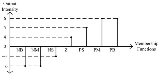
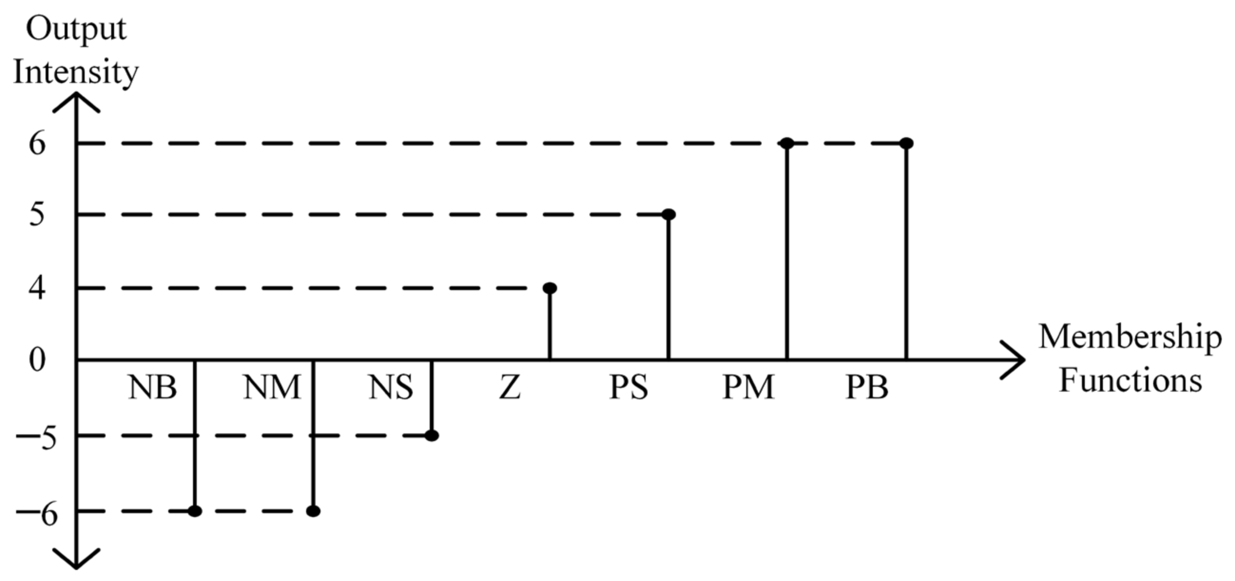
Figure 9 shows the output intensity according to the membership functions. Table 2 shows the definition of If-Then rules. The output intensity can be determined through the If-Then rules, respectively.
Figure 9.
Output intensity according to membership functions.
Table 2.
Definition of If-Then rules.
To reach the steady state faster when the output voltage error is large, the output intensity was set to −6, −5, 4, 5 and 6. For example, if the voltage error is 3 V and the corresponding membership functions are PM and PB, the output intensity is 6, respectively.
3.3. Defuzzification
Defuzzification is the process of converting the inference result into a crisp value that can be used as a control. In the defuzzification process, I*buck is calculated using the weighted-average method. The weighted-average method is determined by dividing the sum of the products of each DOM and the output intensity by the sum of the total DOMs. Since the sum of all DOMs is always 1, it can be omitted for convenience. For example, if Verr is 1, it is assigned to the membership functions PS, PM, and PB, and the corresponding DOMs are 0, 1, and 0, respectively, and the sum of the total DOM is 1. Using the weighted-average method, I*buck is calculated as in (11).
4. Simulation Results
The validity of the proposed FLC-based output voltage control method was verified using PSIM simulation. To ensure a fair comparison between the PI-based output voltage control method and the FLC-based output voltage control method, all the parameters, such as PMD battery charger components, input voltage, and load resistor, were kept identical, and only the control method was varied. The control method was set as the only variable for the simulation, and voltage responsiveness and current ripple were used as performance indicators. A conventional battery equivalent circuit is represented by an R–V circuit and used to stabilize voltage variations and suppress overshoot. However, in this paper, only a resistor was used to more clearly evaluate the dynamic characteristics of the control method, without considering the stabilization effect. The simulation parameters are listed in Table 3.
Table 3.
Simulation parameters.
Figure 10 shows the simulation results of the dynamic characteristics according to gain tuning in PI-based output voltage control. In Figure 10a, a minimal overshoot is observed at the optimized gain. In Figure 10b, the gain was increased to improve responsiveness. In Figure 10b, the settling time of the output voltage is approximately 4.5 ms faster than in Figure 10a. However, the overshoot increased by approximately 320% than Figure 10a. Consequently, the performance of the controller is determined by the gain; the controller gain tuning process is difficult and unsuitable to operate wide range. These limitations make it difficult to improve the dynamic characteristics of the PMD battery charger.
Figure 10.
Simulation results of the dynamic characteristics according to gain tuning in PI-based output voltage control: (a) optimized gain and (b) increased gain.
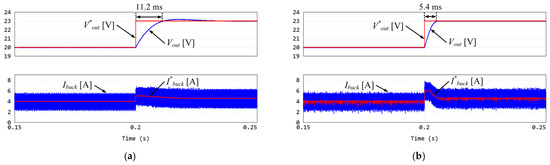
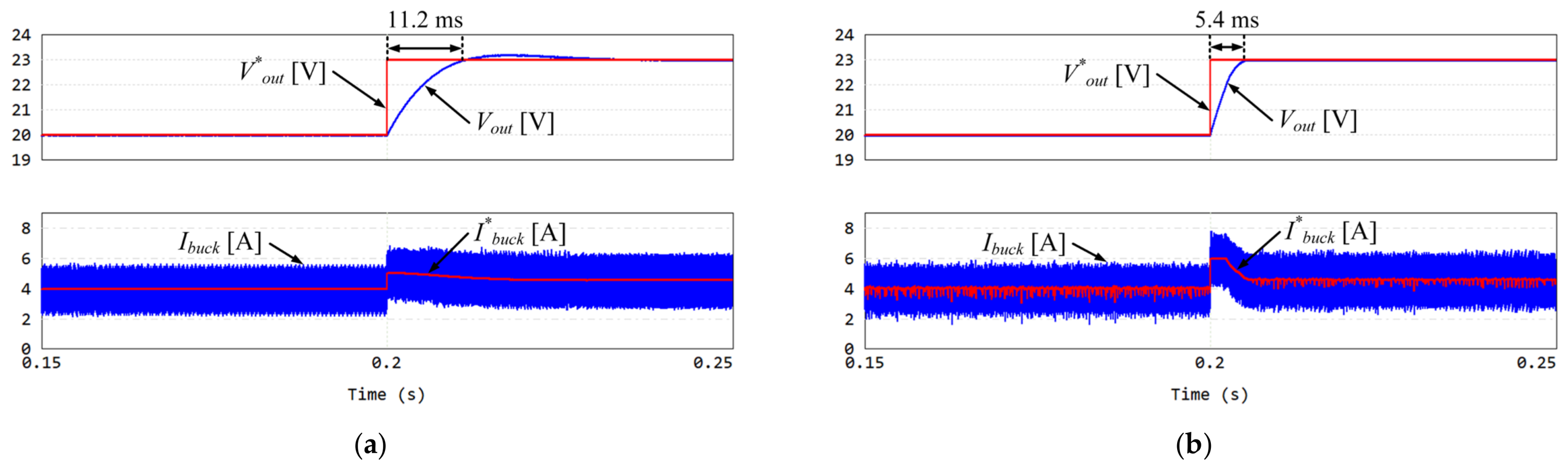
Figure 11 shows the simulation results of the output voltage control in the transient state. The input voltage of the buck converter is 100 V, and the Vout is set from 20 V to 23 V at 0.2 s, considering the operation characteristic of the battery charger. Both control methods are properly controlled according to the V*out. In Figure 11a, the settling time of the output voltage is approximately 11.2 ms. The PI-based output voltage control method can enhance the responsiveness by adjusting the gain. However, since excessive gains may cause overshoot, an appropriate gain is selected. In Figure 11b, the settling time of the output voltage is approximately 5.4 ms and achieves approximately 51.79% faster response than Figure 11a. Additionally, it converges stably to the steady state without overshoot compared to the PI-based output voltage control method.
Figure 11.
Simulation results of the output voltage control in the transient state: (a) PI-based output voltage control method and (b) FLC-based output voltage control method.
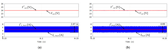
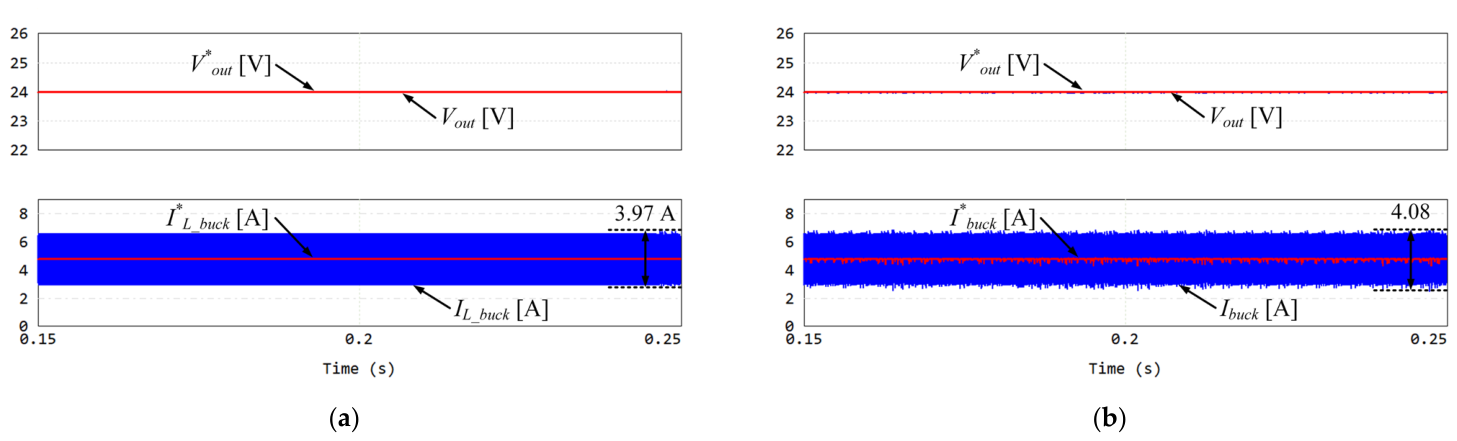
Figure 12 shows the simulation results of the output voltage control in the steady state. The input voltage of the buck converter is 100 V, and the Vout is set to 24 V. Both control methods are properly controlled according to the V*out. The ripple of Ibuck is approximately 3.97 A in Figure 12a and 4.08 A in Figure 12b. Although the proposed FLC-based output voltage control method exhibits a slightly higher current ripple of approximately 2.77%, the difference is negligible. Furthermore, considering its improvement in the dynamic characteristics of the output voltage control, the slight increase in current ripple can be regarded as acceptable. The efficiency of the battery charger is 96.1% in the PI-based output voltage control method and 96% in the FLC-based output voltage control method.
Figure 12.
Simulation results of the output voltage control in the steady state: (a) PI-based output voltage control method and (b) FLC-based output voltage control method.
As a result, the simulation results show that the proposed control method stably improves the dynamic characteristics without overshoot compared to the PI-based output voltage control method, and the performance of the PMD battery charger can also be improved.
5. Experimental Results
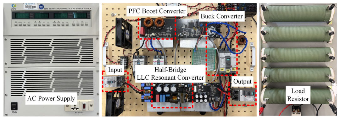
Figure 13 shows the experimental set, which consists of an AC power supply, a PMD battery charger, and a load resistor. The effectiveness of the proposed FLC-based output voltage control method in this paper is verified through the experimental set. As in the simulation, all the experimental conditions were kept identical, and only the control method was varied to ensure a fair comparison between the PI-based and FLC-based output voltage control methods. Voltage responsiveness and current ripple were used as the performance indicators. As in the simulation, to more clearly evaluate the dynamic characteristics of the control method, only a resistor was used instead of a conventional R–V battery equivalent circuit.
Figure 13.
Experimental set.
A single-phase voltage of 220 Vrms/60 Hz was applied using an AC power supply. The PMD battery charger consists of a PFC boost converter, a half-bridge LLC resonant converter, and a buck converter. To manage the heat generated by the circuitry, thermal dissipation was achieved by using heat sinks and cooling fans. These components were adopted to effectively remove the heat generated during operation. The experimental parameters used in the simulation are listed in Table 1.
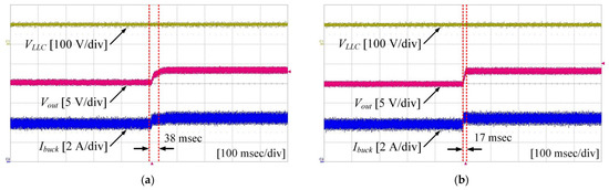
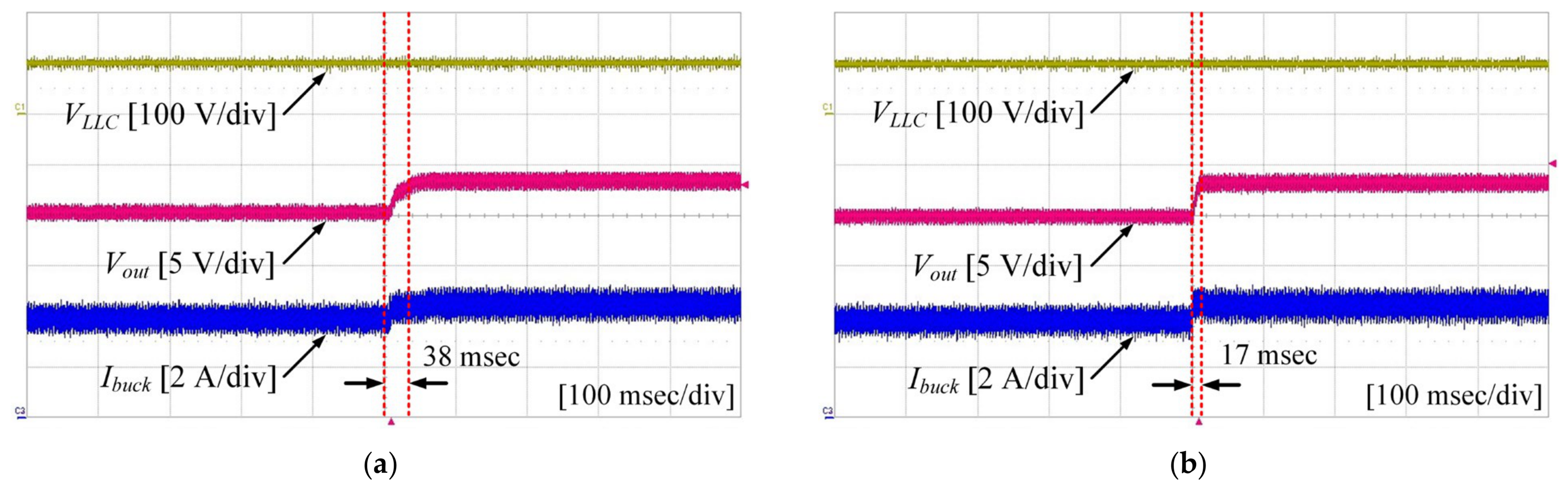
Figure 14 shows the experimental results of the output voltage control in the transient state. The input voltage of the buck converter is 100 V, and the V*out is set from 20 V to 23 V, considering the operation characteristic of the battery charger. Both control methods are properly controlled according to the V*out. In Figure 14a, the settling time of the output voltage is approximately 38 ms. The PI-based output voltage control method can enhance the responsiveness by adjusting the gain. In this paper, for safety considerations, the gains were selected to achieve a fast response without causing overshoot. In Figure 14b, the settling time of the output voltage is approximately 17 ms and achieves approximately 55.26% faster response than Figure 14a. Additionally, it converges stably to the steady state without overshoot compared to the PI-based output voltage control method.
Figure 14.
Experimental results of output voltage control in the transient state: (a) PI-based output voltage control method and (b) FLC-based output voltage control method.
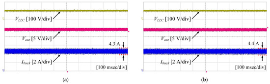
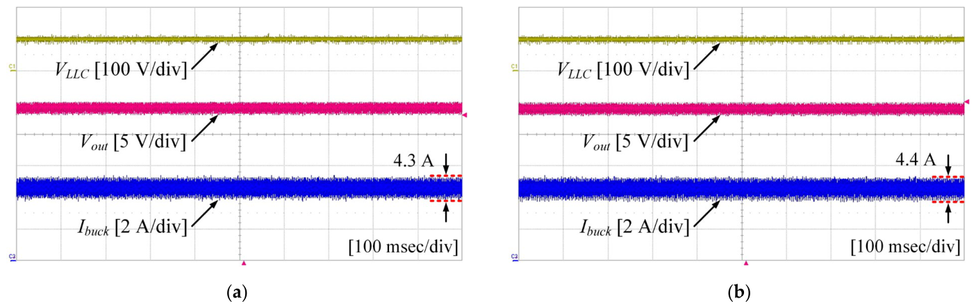
Figure 15 shows the experimental results of the output voltage control in the steady state. The input voltage of the buck converter is 100 V, and the V*out is set to 24 V. Both control methods are properly controlled according to the V*out. The ripple of Ibuck is approximately 4.3 A in Figure 15a and 4.4 A in Figure 15b. Although the proposed FLC-based output voltage control method exhibits a slightly higher current ripple of approximately 2.27%, the difference is negligible. Furthermore, considering its improvement in the dynamic characteristics of the output voltage control, the slight increase in current ripple can be regarded as acceptable.
Figure 15.
Experimental results of the output voltage control in the steady state: (a) PI-based output voltage control method and (b) FLC-based output voltage control method.
The comparative analysis reveals that the errors in the settling time of the output voltage and the output current ripple between the simulation and experimental results are approximately 3.5% and 0.5%, respectively. These minor discrepancies result from parasitic elements of the hardware and sensing noise, which are considered negligible. The waveform and characteristics of the simulation and experimental results exhibit high consistency, thereby verifying the reliability and accuracy of the proposed control method. In addition, although the FLC-based output voltage control method has a slightly higher computational complexity than the PI-based method, the increase in computational burden was not significant in the simulation and experiment. The proposed control method was implemented within the allowable control loop, demonstrating its practical feasibility.
As a result, the experimental results show that the proposed control method stably improves the dynamic characteristics without overshoot compared to the PI control method, and the performance of the PMD battery charger can also be improved.
6. Conclusions
This paper proposes improving the dynamic characteristics of a PMD battery charger using FLC. In general, a PI-based output voltage control method is used to regulate the output voltage of PMD battery chargers. However, when the PI controller gains are tuned to achieve a faster response, overshoot, oscillations, and sensitivity to disturbances may occur, and an appropriate gain tuning process is required. To overcome this limitation, the control method proposed in this paper defines the membership functions based on the error of the output voltage and determines the reference inductor current using the membership functions and output intensity. As a result, the proposed control method exhibits improved dynamic characteristics compared to PI-based output voltage control in the transient state, reducing the settling time by approximately 55.26% and reaching a steady state stably without overshoot. The proposed control method can be utilized not only to PMD battery chargers but also to various fields such as electric vehicles and energy storage systems, contributing to the expansion of the eco-friendly mobility industry. The effectiveness of the proposed control method was verified through simulation and experimental results.
Author Contributions
Conceptualization, software, simulation validation, writing—original draft preparation, and visualization, M.B. and G.K.; experimental validation, Y.B. All authors have read and agreed to the published version of the manuscript.
Funding
This research was supported by the National Research Foundation of Korea (NRF) grant funded by the Korea government (MSIT) (No. RS-2025-23323395).
Data Availability Statement
The original contributions presented in this study are included in the article. Further inquiries can be directed to the corresponding author.
Conflicts of Interest
The authors declare no conflicts of interest.
References
- Nakajima, S. Improved Gait Algorithm and Mobility Performance of RT-Mover Type Personal Mobility Vehicle. IEEE Access 2014, 2, 26–39. [Google Scholar] [CrossRef] [Scilit]
- Nakajima, S. Evaluation of the Mobility Performance of a Personal Mobility Vehicle for Steps. IEEE Access 2017, 5, 9748–9756. [Google Scholar] [CrossRef] [Scilit]
- Choi, J.; Bak, Y. Chattering Reduction Using Improved Switching Functions in the SMC Method for Battery Chargers of PMDs. IEEE Access 2024, 12, 182663–182672. [Google Scholar] [CrossRef] [Scilit]
- Moon, M.; Bak, Y. Dynamic Characteristic Improvement of Battery Charger for PMDs Using a Model Predictive Control. IEEE Access 2024, 12, 25835–25843. [Google Scholar] [CrossRef] [Scilit]
- Seki, H.; Ishihara, S.; Tadakuma, S. Novel Regenerative Braking Control of Electric Power-Assisted Wheelchair for Safety DownHill Road Driving. IEEE Trans. Ind. Electron. 2009, 56, 1393–1400. [Google Scholar] [CrossRef] [Scilit]
- Ibanez, F.M.; Florez, A.M.B.; Gutiérrez, S.; Echeverrría, J.M. Extending the Autonomy of a Battery for Electric Motorcycles. IEEE Trans. Veh. Technol. 2019, 68, 3294–3305. [Google Scholar] [CrossRef]
- Beiranvand, R.; Rashidian, B.; Zolghadri, M.R.; Alavi, S.M.H. A Design Procedure for Optimizing the LLC Resonant Converter as a Wide Output Range Voltage Source. IEEE Trans. Power Electron. 2012, 27, 3749–3763. [Google Scholar] [CrossRef] [Scilit]
- Park, H.M.; Lee, H.W.; Park, C.B.; Lee, J.B.; Kim, J.C.; Lee, J. Analysis and Design of a 50-kW Two Stage Converters for EV Fast Charger with High Efficiency and Wide Output Voltage of 150–1000V. IEEE Access 2025, 13, 37182–37197. [Google Scholar] [CrossRef] [Scilit]
- Musavi, F.; Craciun, M.; Gautam, D.S.; Eberle, W. Control Strategies for Wide Output Voltage Range LLC Resonant DC-DC Converters in Battery Chargers. IEEE Trans. Veh. Technol. 2014, 63, 1117–1125. [Google Scholar] [CrossRef] [Scilit]
- Wu, H.; Li, Y.; Xing, Y. LLC Resonant Converter with Semiactive Variable-Structure Rectifier (SA-VSR) for Wide Output Voltage Range Application. IEEE Trans. Power Electron. 2016, 31, 3389–3394. [Google Scholar] [CrossRef] [Scilit]
- Haque, M.R.; Salam, K.M.A.; Razzak, M.A. A Modified PI-Controller Based High Current Density DC-DC Converter for EV Charging Applications. IEEE Access 2023, 11, 27246–27266. [Google Scholar] [CrossRef] [Scilit]
- Peter, A.K.; Mathew, J.; Gopakumar, K. A Simplified DTC-SVPWM Scheme for Induction Motor Drives Using a Single PI Controller. IEEE Trans. Power Electron. 2023, 38, 750–761. [Google Scholar] [CrossRef] [Scilit]
- Yuce, A. Analytical Design of PI Controller for First Order Transfer Function Plus Time Delay: Stability Triangle Approach. IEEE Access 2023, 11, 70377–70386. [Google Scholar] [CrossRef] [Scilit]
- Sarsembayev, B.; Suleimenov, K.; Do, T.D. High Order Disturbance Observer Based PI-PI Control System with Tracking Anti-Windup Technique for Improvement of Transient Performance of PMSM. IEEE Access 2021, 9, 66323–66334. [Google Scholar] [CrossRef] [Scilit]
- Yang, X.; Guan, J. PI Parameters Tuning for Frequency Tracking Control of Wireless Power Transfer System Based on Improved Whale Optimization Algorithm. IEEE Access 2024, 12, 13055–13069. [Google Scholar] [CrossRef] [Scilit]
- Liu, S.; Liu, M.; Han, S.; Zhu, X.; Ma, C. Tunable Class E2 DC-DC Converter with High Efficiency and Stable Output Power for 6.78-MHz Wireless Power Transfer. IEEE Trans. Power Electron. 2017, 33, 6877–6886. [Google Scholar] [CrossRef] [Scilit]
- Perdukova, D.; Fedor, P.; Sobek, M.; Bacik, J. A Simple Linearization Method of Nonlinear Systems Based on Fuzzy Logic. IEEE Access 2024, 12, 165441–165457. [Google Scholar] [CrossRef] [Scilit]
- Kim, G.; Bak, Y. Improved Sliding Mode Control for Performance Enhancement of PMD Battery Charger Using Fuzzy Logic Control. IEEE Access 2024, 13, 2080–2088. [Google Scholar] [CrossRef] [Scilit]
- Cho, H.H.; Kim, J.W.; Song, M.S.; Yun, C.M.; Cho, G.J.; Tian, Z. Hybrid PI and fuzzy Logic Control for Energy Optimization in Train Operations. IEEE Access 2025, 13, 59366–59376. [Google Scholar] [CrossRef] [Scilit]
- Yonezawa, H.; Yonezawa, A.; Kajiwara, I. Novel Powertrain Vibration Controller with Six Rules-Based Fuzzy Inference for Time-Fluctuated Control Period. IEEE Access 2024, 12, 11972–11986. [Google Scholar] [CrossRef] [Scilit]
- Zhou, M.; Yang, F.; Deng, X. Tracking Control of High-Order Nonlinear Systems with Unknown Control Gains its Application: An Adaptive Fuzzy Control Method. IEEE Access 2024, 12, 141211–141223. [Google Scholar] [CrossRef] [Scilit]



Disclaimer/Publisher’s Note: The statements, opinions and data contained in all publications are solely those of the individual author(s) and contributor(s) and not of MDPI and/or the editor(s). MDPI and/or the editor(s) disclaim responsibility for any injury to people or property resulting from any ideas, methods, instructions or products referred to in the content. |
© 2026 by the authors. Licensee MDPI, Basel, Switzerland. This article is an open access article distributed under the terms and conditions of the Creative Commons Attribution (CC BY) license.