


Abstract
Hybrid CNC and additive manufacturing platforms often rely on host-assisted or otherwise overdimensioned control architectures to achieve deterministic multi-axis motion, increasing system cost and complexity. This paper presents a fully microcontroller-based timer–DMA motion execution architecture that eliminates the need for external processors or FPGA-based execution, enabling deterministic multi-axis synchronization under the tested conditions in a simpler, more cost-effective way. The proposed framework integrates motion planning, precise step-time computation, and hardware-assisted pulse generation within a unified embedded control architecture. The main novelty lies in the systematic use of timer and DMA peripherals to offload time-critical pulse execution from the microcontroller core, allowing it to focus on motion planning and precise step-time computation. Unlike segmentation-based approaches, the duration of each individual step is calculated directly without fixed-interval segmentation, enabling high motion resolution while avoiding per-step interrupts that introduce jitter at high motion speeds. The architecture was validated on a hybrid platform capable of both milling and material extrusion. Experimental results confirmed real-time feasibility within practical on-chip memory limits and demonstrated very small interpolation errors caused mainly by timer quantization, comparable to those observed in host-processor-based motion systems. Machining and additive-manufacturing experiments further confirmed stable execution and accurate trajectory tracking under real operating conditions.
1. Introduction
Hybrid manufacturing platforms that combine additive and subtractive processes are increasingly relevant in Industry 4.0 because they reduce setup changes, enable flexible production, and allow higher-value part finishing within a single machine environment [1,2,3,4,5]. Existing hybrid systems demonstrate clear technological potential, from integrated extrusion–milling platforms to multitasking machine tools, but they also expose an important practical challenge: the motion-control system must remain precise, deterministic, and scalable while the mechanical and process complexity increases [6,7,8,9]. In many implementations, this requirement is addressed using host-assisted or otherwise overdimensioned control architectures, which improve functionality but also increase hardware cost, system complexity, and integration effort. Achieving comparable execution quality on a single low-cost embedded platform is therefore important for the broader accessibility of hybrid manufacturing technology.
From the perspective of CNC research, the foundations of high-performance motion control are well established. Jerk-limited trajectory generation, spline-based interpolation, feed-drive modeling, and feedrate scheduling have all been shown to improve contour accuracy and dynamic smoothness in precision machine tools [10,11,12,13,14,15]. These studies provide the theoretical basis for modern motion planning, but they primarily address the generation of admissible trajectories and usually assume that the low-level execution layer can reproduce the planned motion without introducing significant timing distortion.
In additive manufacturing, the execution layer is equally critical, but the operating conditions are different. Toolpaths are typically denser, short segments are more frequent, and motion quality is strongly coupled with the physical deposition process [16,17,18,19,20,21]. Reviews of additive-manufacturing path planning and fused-filament fabrication consistently show that geometric quality, build time, and repeatability depend not only on toolpath generation but also on the controller’s ability to execute large numbers of motion commands robustly and with limited timing jitter [16,17,18]. This becomes even more demanding in hybrid systems, where the same platform must also satisfy the rigidity and synchronization requirements of subtractive operations [4,5,6,7,8,9].
At the embedded implementation level, the primary challenge is no longer trajectory generation itself, but the deterministic conversion of planned motion into step-level actuation. Real-time embedded systems research consistently emphasizes that latency, jitter, and scheduling overhead fundamentally limit temporal predictability in time-critical applications [22,23]. In motion-control systems, these effects manifest as non-uniform pulse spacing, loss of synchronization between axes, and degradation of trajectory fidelity, particularly at high step frequencies and under dense motion conditions. Experimental investigations on interrupt latency further confirm that even small variations in execution timing can significantly affect system determinism in embedded platforms [24].
To overcome these limitations, a significant body of research has explored hardware-accelerated motion-control architectures. FPGA-based implementations enable deterministic execution by offloading time-critical tasks and exploiting parallel processing capabilities [25,26,27,28,29,30,31]. These approaches have demonstrated improvements in interpolation accuracy, real-time responsiveness, and multi-axis coordination, including optimized interpolation algorithms [31], servo-drive performance enhancement [32], and trajectory planning acceleration [33]. However, despite their advantages, FPGA-based systems introduce increased hardware complexity, longer development cycles, and higher system cost, which limits their suitability for compact and low-cost manufacturing platforms.
In parallel, recent studies have investigated embedded system architectures that combine software flexibility with hardware-assisted execution. Approaches based on DMA-supported data transfer and optimized embedded control pipelines have shown potential for improving timing precision while maintaining computational efficiency [34,35]. In particular, programmable pulse-generation techniques and high-precision timing control mechanisms have been proposed to address step-signal accuracy in real-time control systems [36]. These methods highlight the importance of minimizing CPU intervention during time-critical signal generation, especially in applications requiring high-frequency step outputs.
At the system level, embedded CNC architectures and networked control approaches further illustrate the importance of deterministic timing and synchronization. Embedded CNC systems based on real-time operating systems and industrial communication protocols have demonstrated improved scalability and coordination in multi-axis systems [37,38,39,40]. Additionally, scheduling strategies for multi-core embedded processors have been proposed to improve execution efficiency and real-time responsiveness in CNC applications [40]. More recent research also emphasizes the role of optimization-based control strategies and feedrate planning methods in improving machining efficiency and motion accuracy [41,42].
Widely adopted open-source motion-control frameworks provide further insight into practical implementation strategies. GRBL and grblHAL implement motion execution using segmentation-based planning combined with Bresenham interpolation and per-step interrupt-driven pulse generation on resource-constrained microcontrollers [43,44]. While this approach is computationally efficient and widely adopted, it inherently introduces timing variability at high step rates due to the reliance on frequent interrupt servicing. In contrast, Klipper shifts the computational burden of motion planning to an external host computer, where detailed step timing is precomputed and streamed to the microcontroller [45]. However, the embedded controller still relies on interrupt-based step execution, which can introduce timing limitations under high-frequency operation. LinuxCNC represents a software-centric control architecture typically deployed on more powerful computing platforms, where real-time performance is achieved through dedicated real-time kernels and hardware abstraction layers [46]. Although these systems have achieved broad adoption, they reflect different trade-offs between computational distribution, system complexity, and execution determinism, and none fully eliminate the timing constraints associated with interrupt-driven step generation in embedded implementations.
Classical interpolation techniques, such as Bresenham-based algorithms, remain widely used for synchronized multi-axis stepping [47]. However, these approaches are typically implemented within interrupt-driven frameworks and therefore do not eliminate timing variability introduced by software scheduling. Benchmark analyses of modern motion-control systems further highlight the increasing difficulty of maintaining consistent timing under high-performance conditions [48].
From an application perspective, the impact of execution-layer accuracy is particularly evident in additive manufacturing processes. Studies on fused deposition modeling demonstrate that even small deviations in motion execution can result in measurable dimensional errors and reduced repeatability [49]. These effects are further amplified in hybrid manufacturing systems, where the same platform must satisfy both additive and subtractive process requirements, placing additional constraints on motion precision and synchronization.
Despite these advances, a clear gap remains in the development of embedded motion-control architectures capable of computing and executing the timing of each individual step directly, without relying on segmentation or per-step interrupt execution, while remaining feasible on a single microcontroller platform. Existing solutions typically sustain high step rates through segmentation, host assistance, or frequent interrupt handling, which increases processor load and introduces timing variability at high motion speeds [24,25,43,44,45,46]. This limitation is particularly critical in applications characterized by dense toolpaths and frequent short segments, such as additive manufacturing systems.
To address this challenge, this work proposes a deterministic timer–DMA motion execution architecture for embedded multi-axis motion controllers. The proposed approach systematically exploits hardware timers and DMA peripherals to offload time-critical pulse generation from the microcontroller core, allowing the core to focus on motion planning and step-time computation. In contrast to segmentation-based execution approaches, the duration of each individual step is calculated directly, enabling high motion resolution while avoiding the per-step interrupt overhead that commonly introduces timing jitter at high step rates. A master–slave timer synchronization mechanism is further introduced to ensure deterministic block-level coordination and consistent direction updates between motion segments.
The contributions of this work can be summarized as follows:
- A deterministic step-generation architecture based on coordinated hardware timers and DMA transfers;
- A memory-driven motion execution pipeline that minimizes processor involvement during pulse generation;
- An execution model capable of computing exact step timing without segmentation while maintaining feasibility on a single microcontroller platform;
- Experimental validation of the proposed architecture on a hybrid manufacturing platform combining additive and subtractive processes.
2. Comparison of Motion Execution Concepts and Motivation for the Proposed Architecture
Most open-source motion control firmware used in CNC machines and 3D printers share a common high-level objective: transform a sequence of G-code blocks into synchronized multi-axis motion while respecting kinematic limits. Independent of the implementation, the control pipeline is typically divided into two logical stages. The first stage (planning) determines feasible entry, cruise, and exit speeds for each motion block using lookahead to satisfy acceleration/jerk constraints across block boundaries. The second stage (execution) converts the planned motion into precisely timed step pulses (or equivalent actuator commands) delivered to motor drivers. In practice, the execution stage is often the limiting factor for low-cost embedded platforms because it must sustain high event rates with tight timing jitter.
2.1. Lookahead as a Common Planning Layer (Brief Overview)
Lookahead algorithms are widely used to compute consistent velocity profiles across consecutive blocks. The key output of lookahead is not the detailed mathematical derivation, but the resulting motion profile parameters for each block: entry speed, nominal (cruise) speed, exit speed, and the distances where acceleration ends and deceleration begins. Once these parameters are established, the remaining challenge becomes how to execute the motion with minimal timing distortion at the step-pulse level.
2.2. GRBL-Family Concept: Time-Based Segmentation + Interrupt-Driven Bresenham Stepping (MCU-Centric)
Firmware derived from GRBL concepts (including many CNC controllers and printer firmware that follow the “segment-and-step” approach) executes each planned motion block by dividing it into small constant-velocity segments. The segmentation is typically performed at a fixed time interval Δt (commonly 10 ms, with practical values often in the 5–20 ms range). For each segment, the firmware computes an average segment velocity and the corresponding segment length, then converts that length into an integer number of steps for each axis. Because step counts are integers while segment calculations are generally fractional, a rounding error occurs at each segment; GRBL mitigates cumulative drift by tracking the rounding error and carrying it into subsequent segments as a correction term.
After segment preparation, the real-time execution is performed fully on the microcontroller using a timer interrupt. Inside the interrupt service routine, the firmware uses a multi-axis extension of the Bresenham line algorithm to decide when to step each axis so that the resulting discrete step sequence approximates the desired continuous path [47]. In this approach, a single interrupt source (typically tied to the dominant axis step rate) becomes the global time base for all axes. This structure is computationally efficient and well-suited for small microcontrollers, because it relies primarily on integer arithmetic and a compact per-interrupt routine.
However, this execution model has inherent limitations:
- Approximation due to segmentation: the continuous velocity profile is approximated by piecewise-constant segments. Smaller Δt improves fidelity but increases CPU overhead and segment bookkeeping.
- Shared interrupt timing base: non-dominant axes can only step at the time instants dictated by the dominant-axis interrupt schedule, which may introduce uneven step spacing at low speeds or near equal-step multi-axis motion.
- Interrupt-rate scalability: at high step frequencies (especially in multi-axis motion), interrupt execution time can approach or exceed the time between consecutive interrupts, which directly increases jitter and can result in missed deadlines.
These effects are most visible at low-to-mid step frequencies (often a few kHz) where uneven step spacing can excite mechanical resonances, increase audible noise, and degrade surface quality. Firmware-level smoothing mechanisms (e.g., adaptive step smoothing) can partially reduce these artifacts, but the root cause remains tied to interrupt-driven stepping with a dominant-axis time base.
2.3. Klipper Concept: Host-Computed Exact Step Timing + Event-Queue Execution on MCU (Split Architecture)
Klipper represents a different architecture where computational responsibilities are split between a higher-performance host processor and a microcontroller. The host performs motion planning and generates a detailed schedule of step events. Instead of segmenting motion into constant-velocity pieces, Klipper computes step timings directly, producing an event stream in which each step has an explicit execution time. This reduces approximation error in timing and enables smoother motion when the host has sufficient processing power.
On the microcontroller side, execution is typically event-driven: step events are stored in prioritized buffers, and a high-resolution timer generates interrupts to trigger events. For each step, the firmware must assert the step output and also generate a corresponding falling edge (pulse termination). If implemented purely as separate timed events, this can double the number of interrupts per step unless pulse width is handled by additional hardware support. As step rates increase and multiple axes move simultaneously, the number of time-critical events can become large. In that situation, the execution layer may again become limited by interrupt processing latency, and timer compare updates can introduce measurable jitter when successive events are closely spaced.
Additionally, the split architecture introduces a second constraint: host–MCU communication bandwidth and latency. Current printer speeds are generally compatible with common communication links (UART/USB/CAN), but higher step rates and finer microstepping push toward a future where communication overhead and buffer management become limiting factors unless execution is further offloaded.
2.4. Summary of the Trade-Off and Motivation for the Proposed Timer–DMA Approach
The comparison above highlights a practical trade-off:
- GRBL-style execution is simple and MCU-centric, but relies on segmentation and interrupt-driven Bresenham stepping, which can introduce timing artifacts and scalability limits at higher speeds or complex multi-axis motion.
- Klipper-style execution uses more accurate timing by computing step schedules on a powerful processor, but still depends on interrupt-driven event execution on the MCU and adds complexity and bandwidth constraints.
For next-generation low-cost embedded motion controllers—especially those targeting high path density applications such as fast 3D printing and hybrid manufacturing—there is a clear need for an execution architecture that:
- Preserves deterministic timing at high event rates;
- Reduces or eliminates per-step interrupt overhead;
- Remains feasible on low-cost microcontrollers without requiring a host processor.
These requirements motivate the proposed architecture in this work. The key idea is to offload the time-critical step generation into a timer-triggered DMA pipeline, where precomputed timing/step patterns are streamed from memory to timer/GPIO control registers without CPU intervention for each step. In the next subsection, the proposed motion execution model is introduced, followed by the timer–DMA step generation mechanism and the buffering strategy that enables continuous operation across motion blocks.
3. Proposed Deterministic Timer–DMA Motion Execution Architecture
This section introduces the proposed motion execution architecture. The objective is not to redefine motion planning itself, but to redesign the execution pipeline so that high-quality lookahead planning can be preserved while eliminating the scalability limitations associated with interrupt-dominated step generation.
The proposed architecture is organized into three functional layers, as illustrated in Figure 1:
- Motion Planning Layer
- Step-Time Preparation Layer
- Hardware Execution Layer
Figure 1.
Layered architecture of the proposed motion execution system. The motion planning layer performs lookahead-based velocity profiling and block decomposition. The step-time preparation layer converts kinematic parameters into discrete timer intervals and formats them for DMA transfer. The hardware execution layer streams precomputed timing data to synchronized timers, which generate STEP/DIR signals for the motor drivers. Black arrows indicate transitions between layers, while blue arrows represent the internal data flow within each layer.
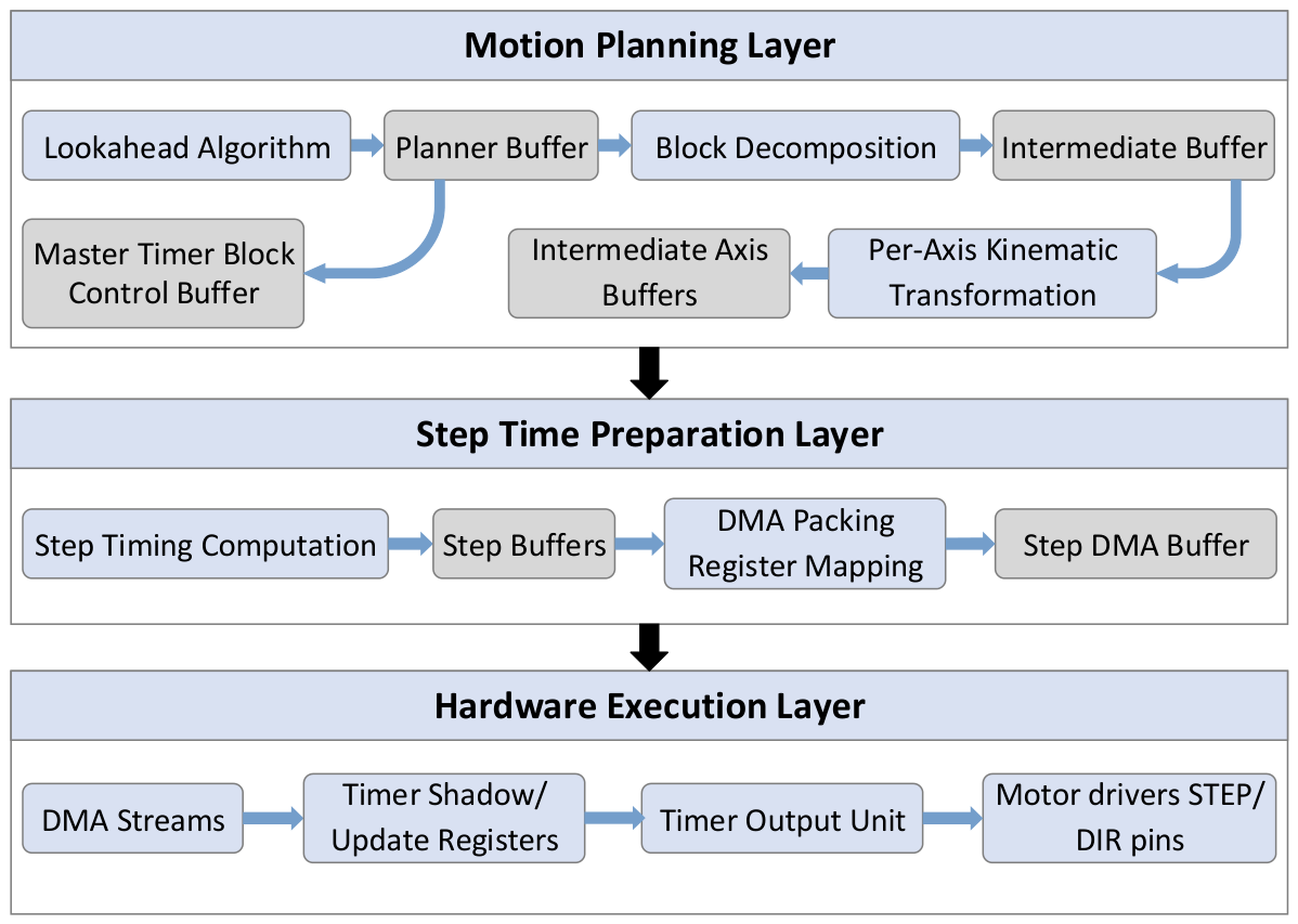
Each layer performs a clearly separated role in the transformation of a high-level motion command into synchronized STEP/DIR pulses delivered to the motor drivers.
The Motion Planning Layer computes physically consistent velocity profiles using a lookahead strategy and decomposes each motion block into acceleration, cruise, and deceleration subsegments. Rounding and synchronization effects are analyzed, and timing correction values are computed to preserve exact segment duration after discretization. The output consists of continuous-time kinematic parameters, axis displacement data, and timing correction values.
The Step-Time Preparation Layer converts these continuous parameters into discrete timer intervals suitable for hardware execution. This includes timing quantization, per-axis step computation, and preparation of memory structures that can be consumed by the DMA engine without real-time computational overhead.
The Hardware Execution Layer is responsible for deterministic signal generation. Precomputed timing blocks are streamed via DMA to synchronized hardware timers, which generate STEP/DIR pulses without requiring a CPU interrupt for every individual step event.
By separating planning, timing synthesis, and hardware streaming into distinct layers, the proposed architecture enables deterministic multi-axis motion while maintaining a microcontroller-only implementation. The following subsections describe each layer in detail.
3.1. Motion Planning Layer
3.1.1. Planner Buffer and Lookahead Optimization
The motion planning stage is implemented using a fixed-size circular planner buffer optimized for deterministic execution on a microcontroller. The lookahead strategy follows principles adopted in modern firmware architectures, including Klipper and other contemporary motion controllers, where consecutive motion segments are evaluated to guarantee physically consistent velocity transitions. In contrast to host-assisted implementations, the complete lookahead computation is performed locally within the microcontroller using a bounded memory structure, ensuring predictable computational complexity.
Each element of the planner buffer represents a single motion segment and stores geometric parameters, velocity constraints, and optimized motion profile values. The internal structure of one planner buffer element is illustrated in Figure 2.
Figure 2.
Internal structure of a planner buffer element showing geometric parameters, velocity constraint parameters, and optimized motion profile outputs generated by the lookahead stage.
From the start and end coordinates of the segment, the axis displacements are computed as:
The total segment length is then obtained as:
The normalized direction ratios:
define the proportional contribution of each axis to the coordinated motion and are stored in the planner buffer element, as shown in the geometric parameter section of Figure 2.
The velocity constraint section of the planner buffer stores squared-domain limits that enable efficient evaluation of admissible transitions. For each segment, the maximum allowable change in squared velocity is determined from classical kinematics:
where is the programmed acceleration. This constraint bounds the transition between entry and exit velocities while preserving acceleration limits.
To improve motion behavior in short or rapidly alternating segments, a reduced virtual acceleration is introduced:
which defines a reduced maximum admissible change in squared velocity:
This constraint limits the maximum velocity difference between the start and end of a segment during lookahead evaluation. In short segments where the nominal acceleration constraint would produce triangular velocity profiles, the smoothed constraint lowers the attainable peak velocity so that a short constant-velocity interval is formed between acceleration and deceleration phases.
As a result, abrupt velocity reversals are mitigated and transitions become dynamically smoother. During execution, however, the nominal acceleration is still applied to reach the reduced peak velocity, ensuring consistency with the machine’s physical capabilities.
After completion of the forward and backward lookahead passes, the optimized motion profile parameters: entry velocity , cruise velocity , exit velocity , and the corresponding acceleration, cruise, and deceleration durations and displacements are stored in the planner buffer element. These optimized values represent the output of the lookahead stage and serve as input to the subsequent intermediate buffering process, where the motion segment is prepared for discrete-time execution within the motion planning layer.
3.1.2. Intermediate Buffer and Axis-Level Execution Preparation
After completion of the lookahead stage, each motion segment is decomposed into up to three non-overlapping subsegments corresponding to acceleration, constant velocity, and deceleration phases. This separation guarantees that each subsegment represents a single kinematic regime, avoiding mixed-state execution during discrete-time conversion.
The resulting subsegments are transferred to the Intermediate Buffer, whose internal structure is shown in Figure 3. This buffer forms the transition between continuous-time motion planning and discrete-time execution. It stores the projected kinematic quantities, the subsegment type, the continuous duration , and the total number of steps required for each axis. Most importantly, it converts the continuous-time duration into hardware timer units:
where is the timer clock frequency.
Figure 3.
Structure of the intermediate buffer element used for subsegment-level discrete-time preparation, including kinematic projection parameters, discrete duration in timer ticks, and deterministic timing error compensation variables.
Because the timer operates in integer ticks, direct conversion introduces quantization effects. Without compensation, these discretization errors would accumulate and lead to temporal misalignment between axes. To prevent this, the intermediate buffer implements a deterministic timing error compensation scheme.
For acceleration phases, the theoretical time corresponding to the last step of a given axis is computed from the kinematic relation:
After integer rounding, the mismatch between the discrete step timing and the total discrete subsegment duration is expressed as:
Instead of distributing this error heuristically, it is decomposed into a base increment applied to all steps and an additional increment applied only to a predefined number of initial steps. This guarantees that the accumulated discrete timing matches exactly while maintaining monotonic step progression. The same procedure is applied during deceleration phases. For cruise segments, the duration is uniformly divided among steps and any remainder ticks are deterministically assigned to early steps to preserve exact timing closure.
While the intermediate buffer holds global subsegment data, synchronized execution requires axis-level state management. Therefore, dedicated Intermediate Axis Buffers, illustrated in Figure 4, are introduced for each active axis. These buffers contain axis-projected velocities, acceleration values, discrete timing parameters, local step counters, and remaining discrete time. By separating global subsegment description from per-axis execution state, the architecture prevents stalls that could occur when axes have significantly different step counts.
Figure 4.
Per-axis intermediate buffer structure storing axis-projected kinematic quantities, discrete timing parameters, and local step execution state for synchronized multi-axis motion.
This layered buffering approach ensures that:
- Continuous-time planning results are converted into exact integer-tick representations;
- All axes share identical subsegment start and end times;
- No cumulative timing drift occurs;
- Multi-axis coordination remains deterministic.
3.1.3. Master Timer Block Control and Direction Synchronization
The DMA-based step streaming architecture transfers precomputed timer parameters directly from memory to hardware timer registers. While this approach eliminates per-step interrupt overhead and ensures deterministic pulse timing, it introduces a structural limitation: direction signals cannot be modified dynamically during step execution.
In a pure DMA-driven configuration, only timer parameters such as ARR and CCR are streamed. GPIO direction pins are not part of the DMA transfer pipeline, and therefore cannot be updated synchronously with individual steps. Any asynchronous direction change would introduce timing jitter or phase misalignment.
To address this limitation, a dedicated Master Timer Block Control Buffer is introduced, as shown in Figure 5. This buffer operates strictly at the block level, synchronizing direction updates and high-level timing control with block boundaries.
Figure 5.
Structure of the master timer block control buffer used for block-level synchronization, direction management, and interrupt scheduling in the timer–DMA execution architecture.
In contrast, the intermediate buffer and intermediate axis buffers operate at the subsegment level, where each block has already been decomposed into acceleration, cruise, and deceleration phases. The master timer, therefore, does not manage subsegment execution; instead, it supervises block-level transitions and ensures that direction changes occur only between consecutive motion blocks.
Its primary functions are to:
- Maintain axis direction states (DIR_X, DIR_Y, DIR_Z, DIR_E);
- Define the master timer period in clock cycles;
- Control the number of interrupt events required to cover the full block duration;
- Guarantee that direction updates occur only at safe synchronization points.
Before decomposition into the intermediate buffer, the total duration of a motion block is converted into timer clock cycles. This value is stored in master-timer-specific parameters. If the block duration can be represented within a single auto-reload register (ARR) value, a single interrupt is sufficient. However, if the required period exceeds the maximum ARR range, the duration is segmented into multiple interrupt events.
Two mechanisms are supported:
- Repetition Counter (RCR), if available on the timer.
- Multiple interrupt events with identical ARR values and a final adjusted ARR value for exact duration matching.
When segmentation is required, the buffer stores:
- Number of interrupt events;
- Remaining interrupt count;
- Final ARR value (if the last period differs from the nominal one).
This guarantees that the total accumulated timer cycles match exactly the required block duration without drift.
Figure 6 presents the execution flow of the master timer interrupt service routine (ISR), which operates at block level and is responsible for direction synchronization and block boundary management.
Figure 6.
Flowchart of the master timer interrupt service routine (ISR) illustrating block-level interrupt handling, direction updates at block boundaries, and synchronized loading of ARR/RCR parameters.
When the interrupt is triggered, the ISR first decrements the remaining interrupt counter. This counter is used when the total block duration cannot be represented by a single timer period.
If the remaining interrupt count is greater than zero, the block is still active. In this case, the next ARR/RCR parameters are loaded and the ISR exits. No direction update is performed during this phase, ensuring that direction remains constant throughout the entire block.
If no remaining interrupts exist, the block is considered completed. A verification step checks whether block termination occurred as expected; otherwise, a desynchronization error is raised.
Once the block is confirmed as completed, the ISR checks whether a new block is available in the control buffer. If a new block exists, the direction of the GPIO pins (DIR_X, DIR_Y, DIR_Z, DIR_E) is updated according to the next block parameters, and the corresponding ARR/RCR values are loaded. Execution then resumes with the new block. If no new block is available, all motors are stopped and the motion process is terminated.
When a hardware repetition counter (RCR) is available on the master timer, the entire block duration can be represented using a single ARR value combined with an appropriate repetition count. In this configuration, only one interrupt occurs per block. If the repetition counter is not available or insufficient, the duration is divided into multiple interrupt events as reflected by the remaining interrupt counter.
This mechanism guarantees that direction changes occur strictly at block boundaries and never during DMA-driven step execution, preserving deterministic timing and synchronization across all axes.
3.2. Step-Time Preparation Layer
The step-time preparation layer converts the discrete subsegment representation obtained from the intermediate buffers into timer-compatible parameters suitable for deterministic DMA-driven execution. In contrast to conventional interrupt-driven step generation approaches, where step events are scheduled and advanced through periodic interrupt service routines, the proposed method precomputes complete timer register configurations in memory and streams them directly to hardware via DMA. This eliminates per-step interrupt handling during execution and ensures strictly deterministic pulse timing independent of MCU core scheduling latency.
For each motion axis (X, Y, Z, and E), a dedicated step-time buffer is allocated, as illustrated in Figure 7. The buffer is organized as a structured two-dimensional array composed of fixed-size timing blocks. Conceptually, the buffer contains 50 rows, each consisting of 100 step-timing entries (50 × 100). This structure enables block-based computation and DMA transfer: timing parameters are calculated and stored in groups of 100 entries, while the outer dimension allows multiple blocks to be prepared in advance.
Figure 7.
Per-axis step-time buffer organization showing 50 × 100 timing blocks, where each entry contains timer parameters (PSC, ARR, CCR) and a block-level multiplicity factor used for repeated DMA transfers during constant-velocity motion.
Each entry in the buffer represents a complete timer configuration for one step event. It contains the timer prescaler (PSC), the auto-reload value (ARR), and the compare register value (CCR), which together define the step period and pulse width. In addition, a multiplicity factor is included to represent repeated identical timing blocks using a single stored block entry. The multiplicity mechanism operates at the level of the fixed 100-element timing block shown in Figure 7, rather than at individual step resolution.
This approach is particularly effective during constant-velocity (cruise) phases, where consecutive groups of 100 step-timing values are identical. Instead of storing and transferring multiple identical 100-entry blocks, a single block is stored together with an associated repetition count. During execution, the DMA transfer of that block is repeated according to the multiplicity value, without recomputing or duplicating the timing entries in memory.
The 50 × 100 organization is chosen to balance three constraints: deterministic memory usage, bounded computational latency during buffer preparation, and compatibility with DMA burst transfer mechanisms. By computing and streaming timing data in fixed-size groups, the architecture guarantees that step preparation never blocks execution and that sufficient timing data are always available for uninterrupted hardware streaming.
3.2.1. Step-Time Computation
Step timing is derived from the kinematic expressions established in the intermediate buffer. For acceleration segments, the displacement corresponding to the i-th step is defined as:
where STEP_RES denotes the axis resolution in millimeters per step. The cumulative time required to reach displacement under constant acceleration is:
The period between consecutive steps is then computed as:
where is the timer clock frequency and is the cumulative time of the previous step.
For 32-bit timers, the computed period can typically be written directly to the ARR register. For 16-bit timers, if the required period exceeds the timer range, a prescaler value is derived such that:
ensuring that the effective timer period remains within hardware limits. The pulse width is defined by the compare register as:
which produces symmetric step pulses.
After rounding to integer tick values, the cumulative time reference is updated to maintain deterministic alignment with the discrete subsegment duration. For constant-velocity segments, the timing computation simplifies to uniform step intervals:
where is the total number of steps for the axis within the subsegment.
For deceleration phases, the time-to-displacement relation follows the symmetric form:
The remaining step of a subsegment is computed to ensure that the accumulated discrete time exactly matches , maintaining consistency with the error-compensated intermediate buffer.
3.2.2. Step DMA Buffer and Hardware Burst Constraints
In microcontroller-based real-time motion systems, DMA controllers often require burst transfers to follow a fixed, contiguous peripheral register sequence (e.g., PSC → ARR → RCR → CCRx). In such architectures, selective register updates are not supported, meaning that the DMA transfer must match the exact hardware-defined order.
In the proposed firmware, only PSC, ARR, and a single CCR channel are actively updated per axis. Because the DMA burst sequence includes additional timer registers, direct streaming from the step-time buffer would not satisfy the required layout.
To address this structural constraint, a dedicated StepDMA buffer is introduced. This buffer reorganizes step timing parameters into a hardware-compatible format, populating unused registers in the burst sequence with zero values while placing the active CCR value in the correct position. Timing entries are copied into this buffer in fixed 100-element blocks before DMA streaming.
It should be noted that this additional buffer layer is required only for microcontrollers whose DMA engines enforce strict burst ordering. On architectures that support selective register transfers or flexible DMA descriptors, the StepDMA buffer can be omitted, and timing values may be streamed directly from the step-time buffer.
The introduction of the StepDMA buffer isolates hardware-specific DMA constraints from the core motion and timing computation layers. As a result, the step-time preparation algorithm remains independent of the underlying DMA implementation, and only the final packing stage must be adapted for different microcontroller architectures.
3.3. Hardware Execution Layer
The hardware execution layer converts the prepared step-time data into synchronized motor drive signals through coordinated use of DMA and hardware timers. This layer consists of a master timer, multiple slave step timers, and the DMA controller, as illustrated in Figure 8.
Figure 8.
Hardware execution layer of the proposed motion control system, including DMA-based register streaming, master timer synchronization, and slave timer pulse generation for multi-axis motor control. Lighter-colored register blocks (PSC, ARR, CCR) represent shadow registers, while darker blocks represent active timer registers.
As shown in Figure 8, the StepDMA buffer provides timer configuration values to the MCU DMA controller, which performs burst transfers directly into the timer registers. Each transfer updates the prescaler (PSC), auto-reload register (ARR), and compare register (CCR) according to the hardware-defined register sequence. These values are written into the timer shadow registers rather than the active counter registers, ensuring that parameter changes do not affect the currently running timer cycle. The new configuration is automatically applied on the next update event (UEV), which guarantees that timing modifications occur only at well-defined boundaries. The use of shadow registers is therefore essential for preventing mid-period distortions and maintaining deterministic pulse generation across all axes.
The step timers (Timer X, Timer Y, Timer Z, and Timer E) operate as slave timers responsible exclusively for pulse generation. After initialization, their counters run autonomously, generating step signals on the corresponding PWM output pins connected to the motor drivers. Because all timer updates are hardware-driven, step generation proceeds without per-step MCU core intervention. Importantly, once started, all timers remain active throughout the entire machining or printing process and are never stopped between motion segments. This guarantees continuous phase alignment across all axes. When a particular axis is not required to move, its timer continues counting, but pulse generation is suppressed by forcing the compare value to exceed the auto-reload value (CCR > ARR). In this condition no output transition is produced, while the timer counter remains perfectly synchronized with the other axis timers that continue generating step pulses. This approach ensures that inactive axes maintain exact timing alignment with active ones, preserving deterministic multi-axis synchronization throughout the entire motion execution.
The master timer provides global synchronization and block-level supervision. At the start of motion execution, the master timer and all slave timers are enabled simultaneously using the hardware trigger mechanism (TRGO), ensuring that all counters begin operation on the same clock edge. This guarantees cycle-accurate alignment across all axes. Because this synchronization is performed entirely in hardware, no software latency is introduced during timer start-up, ensuring deterministic phase alignment between all motion axes from the beginning of execution.
During motion execution, the master timer tracks block duration independently of the step timers. Upon block completion, its interrupt service routine performs direction updates and loads the timing parameters for the subsequent block, as described in Section 3.1.3. Direction changes, therefore, occur strictly at block boundaries and remain fully synchronized with the step execution process.
Figure 9 illustrates the DMA-complete callback mechanism associated with step block streaming. After each 100-element timing block is transferred, the multiplicity factor is evaluated. If the multiplicity counter remains greater than zero, the same block is retransmitted without recomputation. When the counter reaches zero, the buffer index advances to the next block within the StepDMA buffer. This mechanism enables continuous streaming during constant-velocity motion and seamless transitions between subsegments.
Figure 9.
Flowchart of the DMA completion routine managing multiplicity counters and sequential transmission of step-time blocks during motion execution. The symbols “−−” and “++” denote decrement and increment operations, respectively.
In this execution structure, timing generation, block supervision, and data streaming are clearly separated. The DMA controller manages register updates, the slave timers generate pulses, and the master timer enforces synchronized block transitions. The result is deterministic multi-axis motion control with hardware-aligned execution and precise direction management.
4. Experimental Platform
4.1. Mechanical Design of the Hybrid Manufacturing System
The proposed motion execution architecture was experimentally validated on a custom-developed hybrid CNC and additive manufacturing platform, denoted as JLABsmartCNC. The mechanical structure is shown in Figure 10, where the left image presents the 3D CAD model and the right image illustrates the implemented prototype. The principal components are numerically labeled in the figure.
Figure 10.
Hybrid CNC/Additive Manufacturing platform (JLABsmartCNC): (a) 3D CAD model; (b) implemented prototype. Main components: 1—stationary base, 2—mounting platform, 3—T-slot machining table, 4—magnetically mounted aluminum heated bed for additive manufacturing, 5—removable filament extruder, 6—fixed milling spindle, 7.1–7.3—X/Y/Z-axis servo motors, 8—movable gantry/tool-head structure, 9—pneumatic Z-axis brake, 10.1–10.3—ball-screw transmission systems. The white arrows indicate the mounting and removal direction of the printing table, while the gray arrows indicate the mounting and removal direction of the extruder.
The base frame (1) is constructed from welded structural steel profiles to ensure mechanical rigidity during both subtractive and additive operations. A reinforced support structure (2) carries the working table assembly. For machining applications, a T-slot aluminum table (3) is mounted to enable secure workpiece clamping. For additive manufacturing, a removable heated printing bed (4) is mounted using magnets above the machining table, enabling quick installation and removal.
The tool carriage integrates a fixed milling spindle unit (6) and a removable extrusion head (5). The spindle remains permanently mounted to ensure structural rigidity during machining, while the extrusion module can be quickly exchanged for additive manufacturing operations.
Linear motion is achieved using precision ball screws (10.1–10.3) driven by servo motors (7.1–7.3). The X-axis motor (7.1) drives the base carriage, the Y-axis motor (7.2) actuates the cross-slide, and the Z-axis motor (7.3) controls vertical motion of the tool head. Linear guide rails (8) ensure low-friction, high-precision translation. A pneumatic brake mechanism (9) is integrated on the Z-axis to prevent unintended vertical displacement during power-off conditions.
The nominal travel ranges are 400 mm (X), 325 mm (Y), and 300 mm (Z). This working envelope allows evaluation of both high-speed additive toolpaths and load-intensive milling trajectories, providing a representative platform for validating deterministic multi-axis motion control.
It should be noted that the CAD model in Figure 10a illustrates the machine configured for hybrid operation, including the extrusion head and removable printing bed. In contrast, the physical prototype shown in Figure 10b is configured for machining, where the extrusion module and printing bed are removed and a workholding vise is mounted on the T-slot table.
4.2. Control System Architecture
The control architecture of the experimental platform is illustrated in Figure 11. The system is centered around a custom Electronic Control Unit (ECU) based on an STM32F767 microcontroller. This unit implements the complete motion planning and timer–DMA execution framework described in Section 3.
Figure 11.
Block diagram of the control hardware architecture, including the STM32F767 ECU implementing the timer–DMA motion control framework, axis servo drives, VFD spindle control, extrusion and thermal subsystems, communication interfaces, and safety elements.
Each linear axis is driven by an AC servo motor (X, Y, Z) with a dedicated servo drive. The drives operate in closed-loop configuration using encoder feedback, while receiving step-and-direction signals generated by the proposed deterministic timer architecture. This configuration allows evaluation of step-timing precision independently of internal motor commutation algorithms.
The additive manufacturing subsystem consists of an extruder stepper motor, heater element, and NTC temperature sensor. Temperature control is performed by the ECU using a closed-loop PID regulation algorithm. The heated printing table includes an 800 W heater and dedicated NTC feedback channel.
Subtractive manufacturing is supported by a three-phase spindle motor controlled through a Yaskawa GA500 variable frequency drive (Yaskawa Electric Corporation, Kitakyushu, Japan). Communication between the ECU and VFD is realized via RS485 MODBUS, enabling real-time spindle speed control and monitoring.
User interaction and supervision are provided through two interfaces:
- A custom PC application communicating via RS232;
- A 10-inch HMI touchscreen connected via RS485 MODBUS.
Safety is ensured using inductive limit switches for homing and software-level boundary detection, supplemented by mechanical end-stop protection.
The combination of servo-driven precision axes, hybrid manufacturing capability, and real-time communication interfaces makes the platform suitable for validating the deterministic timer–DMA motion execution architecture under realistic operating conditions.
To improve reproducibility and facilitate engineering implementation of the proposed architecture, a summary of the key hardware and firmware parameters is provided in Table 1. The table consolidates the main configuration details of the microcontroller platform, timer allocation, DMA operation, buffer organization, and execution model. This overview complements the detailed architectural description presented in Section 3 and enables straightforward replication of the proposed motion control approach on comparable embedded systems.
Table 1.
Summary of key implementation parameters for reproducibility of the proposed motion control architecture.
While the presented implementation is based on the STM32F767 platform, the overall architecture is portable to other microcontrollers featuring comparable timer and DMA capabilities, with only minor adaptation required for hardware-specific register mappings.
5. Experimental Evaluation of the Proposed Motion Execution Architecture
5.1. RAM Utilization of the Proposed Buffer-Based Motion Control Architecture
The proposed motion control system relies on a multi-layer buffer architecture designed to support deterministic motion execution while minimizing MCU core intervention. Because trajectory planning, step-time computation, and execution scheduling are performed entirely on the microcontroller, evaluating the memory footprint of the algorithm represents an essential part of the experimental analysis.
All buffers are statically allocated to ensure deterministic runtime behavior. Static allocation guarantees that memory regions remain continuously available during operation and avoids the unpredictable delays associated with dynamic memory allocation. In real-time motion control systems, dynamic allocation may introduce timing variability that could compromise deterministic execution. Static allocation, therefore, ensures predictable memory access across the entire motion pipeline.
Dedicated hardware timers are assigned to each motion axis. The X-axis uses TIM2, the Y-axis TIM5, the Z-axis TIM3, and the extruder axis TIM4, while TIM1 acts as the master timer responsible for global block-level synchronization and direction management. This timer configuration directly influences the memory requirements of buffers responsible for step timing storage and DMA streaming.
Table 2 summarizes the memory consumption of the primary buffers used in the proposed architecture. The motion execution subsystem requires approximately 302 kB of RAM, corresponding to roughly 60% of the available memory of the microcontroller platform. Build-time analysis performed in STM32CubeIDE shows that the complete firmware occupies approximately 393 kB of RAM (77%), including stack and heap allocations. The remaining memory margin is sufficient for interrupt handling, temporary runtime variables, and additional machine functions. No stack overflow or memory exhaustion was observed during extended experimental operation.
Table 2.
Memory consumption of the primary motion control buffers used in the proposed architecture.
The size of the step buffers differs between axes due to the timer architecture used for step generation. The X and Y axes employ 32-bit timers (TIM2 and TIM5), which allow direct representation of larger timing values and therefore require step buffers of approximately 60 kB each. In contrast, the Z and E axes use 16-bit timers (TIM3 and TIM4), where the smaller counter range results in step buffers of approximately 30 kB per axis.
A similar variation appears in the StepDMA buffers. Two factors contribute to these differences. First, the timer architecture (32-bit versus 16-bit) influences the number and size of values transferred during DMA bursts. Second, the selected timer channel determines the register sequence required by the DMA controller. When step generation uses higher-numbered capture/compare registers (e.g., CCR3), the DMA burst must still include the preceding registers (CCR1 and CCR2) to maintain the contiguous register layout required by the hardware. Consequently, additional placeholder values are inserted in the StepDMA buffers, slightly increasing their memory footprint.
Further optimization is possible in future implementations. In most operating conditions, the prescaler (PSC) values stored in the step buffers could be omitted. On platforms with 32-bit timers, prescaler adjustment is rarely required, while 16-bit timers only require prescaling during extremely slow motion. In such cases, multiple timer cycles may be aggregated to generate a single step event, allowing PSC values to be removed from the buffers and potentially reducing step-buffer memory usage by more than 30%.
The architecture can also scale to microcontrollers with larger memory capacities. Devices offering up to 1 MB of RAM would allow larger buffers and support additional motion axes without structural changes to the algorithm, enabling application of more complex CNC systems while preserving deterministic execution.
Unlike distributed motion control architectures that rely on external host processors for trajectory planning and scheduling, the proposed system performs all planning, synchronization, and step-time computation directly on the microcontroller. Host-based solutions typically operate on single-board computers equipped with gigabytes of RAM, where motion planning and buffering occur before commands are transmitted to the embedded controller. The presented architecture demonstrates that advanced multi-axis motion control can be implemented using a single embedded platform with limited on-chip memory while maintaining deterministic real-time behavior and avoiding the latency and complexity associated with host–MCU communication.
5.2. Real-Time Execution Performance of the Proposed Motion Architecture
5.2.1. Motion Accuracy and Trajectory Validation
The real-time performance of the proposed motion control system depends primarily on the time required to compute step timing values before they are streamed to the hardware timers. In the presented architecture, the execution of step pulses is handled entirely by hardware timers synchronized through the master–slave timer topology described in Section 3.3. The DMA controller transfers precomputed timer parameters from memory to the timer registers, eliminating the need for MCU core intervention during step generation. Consequently, the processor workload is limited to preparing timing values and filling the step buffers in advance of execution.
The most computationally demanding operation occurs during the calculation of individual step timings in acceleration and deceleration segments, where each step interval must be computed explicitly due to continuously varying velocity. In contrast, constant-velocity (cruise) segments require significantly fewer computations because identical timing values can be reused for multiple consecutive steps using the multiplicity mechanism described in Section 3.2.
To evaluate the computational feasibility of this approach, the execution time required to compute and store a single step timing entry in the step buffer was measured using the DWT (Data Watchpoint and Trace) hardware cycle counter available in the ARM Cortex-M7 core of the STM32F767 microcontroller. Measurements were performed during the acceleration phase of a motion segment, representing the worst-case scenario due to continuously varying velocity. Since acceleration and deceleration phases are mathematically symmetric, only acceleration measurements are reported.
Without compiler optimization, the average execution time required to compute and store a single step timing entry is approximately 480 CPU cycles. When the firmware is compiled with O3 optimization and the ffast-math option, the execution time decreases to 288 CPU cycles per step. The square-root operation required for velocity calculation represents the dominant computational cost. Alternative Newton–Raphson approximations were experimentally evaluated but did not provide better performance than the optimized floating-point implementation generated by the compiler.
Given the MCU clock frequency of 216 MHz, the time required to compute and store a single step value can be expressed as:
The mechanical system used in the experiments employs AC servo motors with a maximum rotational speed of 3000 rpm, driving ball screws with a 5 mm pitch. The maximum achievable linear velocity is therefore:
With a machine positioning resolution of 1 µm, the corresponding maximum step frequency becomes:
which corresponds to a required step period of:
In coordinated multi-axis motion, the velocity components are distributed among the participating axes, meaning that it is physically impossible for all axes to simultaneously operate at their maximum linear velocity. Typical machining trajectories utilize less than 60% of the maximum axis velocity. Assuming this conservative worst-case scenario, the available computation time per step becomes approximately:
Since the time required to compute a single step timing entry is approximately 1.33 µs, the controller can comfortably compute timing values for multiple axes within the available time window while still maintaining sufficient processing margin. Because step pulses themselves are generated entirely by hardware timers through DMA streaming, the achievable step rate is not limited by interrupt execution time or software latency.
During constant-velocity segments, the computational workload is further reduced because step timing values remain constant. In this case, the multiplicity factor allows the same timing block to be reused for multiple consecutive steps without recalculation. As a result, the processor load during cruise motion becomes nearly independent of the number of executed steps.
To verify the correctness of the proposed step-timing computation algorithm and the resulting motion trajectories, experimental evaluation was performed using the STM32F767-based control system. During execution, the firmware transmitted the computed step-timing parameters together with the corresponding axis direction signals to a host PC via a serial interface prior to hardware execution. The collected data were processed using custom Python 3.7.6 (Python Software Foundation, Wilmington, DE, USA) scripts to reconstruct velocity profiles, displacement trajectories, and interpolation errors.
To evaluate the robustness of the proposed architecture under a wider range of motion conditions, the test trajectory was extended beyond simple linear interpolation. The evaluated trajectory includes a combination of:
- Linear interpolation (G01);
- Circular interpolation (G02/G03);
- Rapid direction reversals (zig-zag motion);
- Short segments near zero velocity;
- Coordinated multi-axis motion involving all three axes.
These elements were selected to expose potential timing quantization effects, synchronization errors, and worst-case execution conditions that are not observable in simple trajectories.
The evaluated motion segments are summarized in Table 3 using representative G-code commands.
Table 3.
Representative G-code motion segments used for experimental validation, covering linear and circular interpolation, direction reversals, low-speed segments, and coordinated multi-axis motion.
Figure 12 illustrates the resulting velocity and displacement profiles for all axes, showing the evolution of motion along the X, Y, and Z directions during the evaluated trajectory. The plots demonstrate the expected acceleration, cruise, and deceleration behavior derived from the step-timing computation algorithm. In addition, the profiles confirm that all axes remain fully synchronized throughout the motion, as the transitions between motion phases occur simultaneously across the participating axes. Figure 13 presents the resulting joint velocity profile of the tool center point, obtained by combining the velocity components of the participating axes.
Figure 12.
Velocity and displacement profiles for the X, Y, and Z axes generated by the step-timing computation algorithm during the evaluated motion trajectory.
Figure 13.
Joint velocity profile of the tool center point obtained from the combined motion of all participating axes.
To evaluate interpolation accuracy, the executed trajectory was compared with the ideal interpolated path derived directly from the input G-code commands. Figure 14 presents a three-dimensional comparison between the generated trajectory and the ideal reference trajectory. The two curves exhibit nearly indistinguishable overlap, indicating that the computed step timings accurately reproduce the intended toolpath even under complex multi-segment motion.
Figure 14.
Comparison between the generated trajectory and the ideal interpolated path in three-dimensional space.
For quantitative evaluation, the axis-wise tracking error was computed as the difference between the generated and ideal positions for each axis. As shown in Figure 15, the tracking error remains below 0.008 mm for the majority of the evaluated trajectory. A higher deviation of up to 0.014 mm was observed in the Y axis during segments involving rapid motion. These segments correspond to non-machining rapid positioning movements, where high speed is prioritized over interpolation precision.
Figure 15.
Axis-wise tracking error between the generated trajectory and the ideal interpolated motion for X, Y, and Z axes.
The observed deviations primarily result from finite numerical resolution when converting computed timing values into integer timer register values. In other words, minor quantization effects arise due to rounding of timing values to match the hardware timer resolution rather than from algorithmic inaccuracies.
When an axis is stationary, the tracking error becomes zero, indicating exact convergence to the commanded discrete position. The positioning resolution of the controller is 0.001 mm (1 µm), corresponding to the configured motion step resolution. The small errors observed during motion, therefore, reflect finite timer granularity rather than inaccuracies in the final attained position.
Finally, the joint three-dimensional trajectory error was evaluated using the Euclidean distance between the generated and ideal positions:
The resulting error profile is shown in Figure 16. The maximum joint spatial error observed during the evaluated trajectory is approximately 0.008 mm under typical operating conditions, while a peak value of approximately 0.014 mm occurs during rapid multi-axis positioning segments. These results confirm that the proposed timer–DMA motion execution architecture achieves high positioning accuracy while maintaining deterministic real-time behavior and minimal processor load.
Figure 16.
Joint three-dimensional trajectory error computed as the Euclidean distance between the generated and ideal positions.
5.2.2. Hardware Timing Validation and Jitter Analysis
The proposed motion-execution architecture employs independent hardware timers for each axis, fully synchronized through a shared timing mechanism and combined with a DMA-driven parameter streaming approach. In this design, timer parameters are preloaded in advance without relying on per-step interrupts, enabling deterministic pulse generation under the tested conditions. As a result, the output step signals directly reflect the calculated timing sequence, and intrinsic timing jitter is theoretically minimized, with no observable timing variation detected within the resolution of the measurement instrument.
To experimentally validate this behavior, a simplified test case was selected to enable high-resolution measurement of step signals using an oscilloscope. Two synchronized axes (X and Y) were commanded using the following G-code sequence:
During execution, the computed timer parameters were transmitted to a host PC via a serial interface. Simultaneously, the generated step signals were measured directly at the motor driver STEP inputs using a Rigol MSO5354 digital oscilloscope (Rigol Technologies, Beijing, China). The captured waveforms were exported as CSV files and processed using custom Python 3.7.6 (Python Software Foundation, Wilmington, DE, USA) scripts to extract edge timestamps and compute pulse-to-pulse periods.
The measured step periods were then compared with the analytically calculated values, and the resulting period jitter was evaluated as a function of time. Figure 17 presents the period jitter for the X axis.
Figure 17.
Period jitter as a function of time for the X axis, obtained by comparing measured step periods with the corresponding calculated values across 55,000 consecutive steps.
The analysis was performed using 55,000 consecutive step intervals, yielding the following results:
Sampling interval:
Maximum absolute jitter:
RMS jitter:
Mean jitter:
Standard deviation:
The observed jitter is bounded by the oscilloscope sampling interval and therefore does not represent intrinsic timing variation in the control system. Instead, it originates from the discrete-time sampling of the measurement instrument. This is further confirmed by the zero mean jitter value, indicating the absence of systematic timing error. Consequently, the residual variation of approximately ±0.05 µs reflects the quantization effect of the measurement process rather than any non-deterministic behavior of the proposed architecture.
Figure 18 presents the corresponding jitter profile for the Y axis (60,000 consecutive step intervals). The results are consistent with those obtained for the X axis, confirming deterministic timing behavior across multiple axes under synchronized operation.
Figure 18.
Period jitter as a function of time for the Y axis, demonstrating consistent deterministic timing behavior under synchronized multi-axis motion.
In addition, Figure 19 shows the histogram of the measured jitter for the X axis. All observed values are confined within the range of ±0.05 µs, which corresponds to the oscilloscope sampling interval. This indicates that the measured variations are entirely bounded by the measurement resolution and do not reflect intrinsic timing fluctuations of the control system.
Figure 19.
Histogram of measured period jitter for the X axis. All values are confined within ±0.05 µs, corresponding to the oscilloscope sampling interval.
5.2.3. High-Speed Multi-Axis Performance and Benchmark Comparison
The performance of the proposed motion-execution architecture was further evaluated in the context of existing step-generation approaches, such as the Klipper firmware. The Klipper benchmark characterizes the minimum number of timer ticks required between consecutive step events to ensure reliable multi-axis operation without timing instability. Reported results indicate that, depending on the microcontroller and system configuration, stable operation for three synchronized axes typically requires between 150 and 400 timer ticks per step interval [48].
To assess the capability of the proposed system under comparable conditions, an experimental test was conducted in which all three axes were driven simultaneously at a minimum step interval of 108 timer ticks. This corresponds to a step period of 1 µs. In order to isolate the timing performance of the controller, the motors were disconnected during this test, and only the generated step signals at the driver interface were measured.
Under this configuration, a step period of 1 µs corresponds to an equivalent theoretical motion speed of 1000 mm/s (60,000 mm/min) for a step resolution of 1 µm. While such speeds exceed practical mechanical limits, they provide a useful stress test for evaluating the timing capabilities of the control system.
Figure 20 shows the generated step signals for the three axes under these conditions. The signals exhibit stable and uniform pulse generation across all axes, with no observable distortion or loss of synchronization.
Figure 20.
Step signals generated for three synchronized axes at a step period of 1 µs (108 timer ticks), demonstrating stable high-frequency pulse generation (X-axis: yellow, Y-axis: cyan, Z-axis: magenta).
Figure 21 presents the corresponding oscilloscope measurement for 9999 consecutive pulses. The measured period statistics indicate an average period of 1.000 µs, with identical minimum and maximum values and zero measured deviation within the resolution of the instrument.
Figure 21.
Oscilloscope measurement of step signals for three synchronized axes for 9999 consecutive pulses (yellow, cyan, and magenta correspond to the X-, Y-, and Z-axes, respectively). The measured period remains constant at 1.000 µs with no observable deviation within the resolution of the instrument.
These results demonstrate that the proposed architecture is capable of generating synchronized step pulses for three axes at significantly lower timer intervals than those typically required in software-driven approaches. This confirms that the elimination of per-step interrupt handling, combined with DMA-based timer control, removes the processing constraints associated with conventional step-generation methods.
Consequently, the proposed system enables high-frequency, multi-axis step generation with deterministic timing behavior, providing a substantial margin with respect to the minimum timing requirements observed in existing motion-control frameworks.
Although a direct experimental comparison with interrupt-driven implementations (e.g., GRBL or Klipper) on identical hardware was not performed, the presented results demonstrate deterministic step signal generation under controlled timing conditions. The comparison with literature-reported benchmark ranges provides contextual reference, while the proposed architecture focuses on eliminating timing variability at the hardware level. A direct head-to-head comparison under identical conditions remains an important direction for future work.
5.3. Practical Validation in Machining and Additive Manufacturing
To validate the proposed motion execution architecture under real operating conditions, a series of machining and additive manufacturing experiments were conducted on the JLABsmartCNC platform. In total, 100 CNC-machined parts and 100 additively manufactured parts were produced and evaluated under different process conditions.
Figure 22 illustrates selected outcomes from these experiments, showing one CNC-machined part (Figure 22a) and two 3D-printed parts (Figure 22b) featuring geometries that require coordinated multi-axis motion and continuous trajectory execution. The printed parts include geometrical features such as inclined surfaces, sharp edges, and varying cross-sections, which are sensitive to motion synchronization and trajectory accuracy.
Figure 22.
Practical validation results of the proposed motion execution architecture: (a) CNC-machined part produced on the JLABsmartCNC platform; (b) 3D-printed parts produced in additive manufacturing mode.
These examples demonstrate the capability of the proposed architecture to execute complex toolpaths under real operating conditions while maintaining stable motion behavior. To complement this visual validation, a structured statistical evaluation of dimensional accuracy was performed across the full set of produced parts, as detailed in the following subsections.
5.3.1. Metrology Protocol and Sampling Plan
A total of 100 CNC-machined parts and 100 additively manufactured parts were produced using predefined geometries with known nominal dimensions. The test geometries included linear features, circular contours, and combined multi-axis trajectories designed to excite coordinated motion across all axes.
Dimensional measurements were performed using calibrated digital calipers (resolution 0.01 mm) and, where applicable, micrometer measurements for smaller features. For each part, multiple critical dimensions were measured, and the maximum absolute deviation from the nominal value was recorded. The reported results include mean error, standard deviation, root mean square (RMS) error, 95th percentile error, and maximum error for each experimental group and tool diameter.
5.3.2. CNC Machining Accuracy Evaluation
The CNC machining experiments were conducted using multiple cutting tools with different diameters to evaluate the influence of tool size on achievable accuracy. Table 4 summarizes the statistical results obtained across 100 machined parts.
Table 4.
Statistical evaluation of CNC machining accuracy (100 parts).
The results show that machining accuracy remains consistently on the order of 0.01 mm across all tested configurations. As expected, smaller tool diameters exhibit slightly improved accuracy due to reduced cutting forces and lower tool deflection. The low standard deviation across all groups indicates stable and repeatable machining performance. Because correct part geometry depends on coordinated multi-axis motion, the small dimensional deviations also indirectly indicate that axis synchronization is maintained with sufficient accuracy under the tested machining conditions. The RMS error and 95th percentile values further confirm that the majority of deviations remain within a narrow tolerance band, with no significant outliers observed across the dataset.
5.3.3. Additive Manufacturing Accuracy Evaluation
A similar evaluation was performed for additive manufacturing using different nozzle diameters to assess the combined effect of motion control and process-related factors. Table 5 presents the statistical results for 100 printed parts.
Table 5.
Statistical evaluation of FDM dimensional accuracy (100 parts).
The results confirm that dimensional accuracy is typically better than 0.10 mm, consistent with expectations for well-calibrated FDM systems. Improved accuracy with smaller nozzle diameters is observed due to finer material deposition and reduced extrusion width.
It is important to note that, unlike CNC machining, the dominant contributors to dimensional error in FDM processes are material-related effects, including thermal shrinkage, filament flow dynamics, and layer adhesion behavior. These factors introduce variability that is largely independent of the motion execution system. The relatively low standard deviation observed across all test groups indicates that the motion control architecture does not introduce significant additional variability compared to inherent process-related effects [49].
5.3.4. Discussion
The statistical results indicate that the proposed timer–DMA architecture provides consistent and repeatable motion execution across both subtractive and additive manufacturing processes. The measured accuracy in CNC machining aligns with the previously reported trajectory error bounds, suggesting that numerical precision is preserved under practical cutting conditions.
For additive manufacturing, the achieved accuracy is comparable to values reported for high-quality FDM systems, indicating that the motion controller is unlikely to be a limiting factor in print precision under the tested conditions. Instead, process-related material behavior remains the dominant source of deviation.
Overall, the presented results address the limitations of purely qualitative validation and show, through statistically supported measurements, that the proposed architecture achieves reliable and predictable performance under practical operating conditions.
The validation methodology presented in this work distinguishes between three complementary aspects: (i) algorithm-level correctness verified through trajectory reconstruction, (ii) signal-level determinism validated through oscilloscope measurements of step timing, and (iii) machine-level performance evaluated through dimensional accuracy tests. While dimensional measurements include contributions from mechanical dynamics and process-related factors, they provide a practical indication of system-level performance. Direct measurement of tool-center-point tracking error under load conditions is considered as future work.
5.4. Comparative Motion Performance and Speed Potential Relative to High-Speed FDM Printers
In hybrid machine configurations, the achievable acceleration and feed rate are inherently limited by the increased moving mass of the multifunction toolhead. Because the same mechanical structure must support both the milling spindle and additive manufacturing components, the resulting inertia constrains the dynamic response of the system. This limitation is primarily mechanical in nature and does not originate from the motion execution architecture itself. At the same time, the hybrid configuration offers a significant practical advantage by enabling both subtractive and additive operations within a single platform using a unified control framework.
When the same motion-control approach is applied to a dedicated additive manufacturing system, where the milling-related mass is removed, the reduction in moving inertia allows substantially higher acceleration and travel speed. In this case, system performance becomes increasingly influenced by motion resolution and timing capability rather than structural constraints.
This distinction becomes particularly relevant when compared with conventional high-speed FDM printer architectures, which commonly employ belt-driven mechanisms with relatively coarse commanded resolution. A typical configuration using a 20-tooth GT2 pulley, a 200-step motor, and 16× microstepping results in an effective step resolution of
which is approximately 12.5 times lower than the 1 μm motion resolution used in the proposed system. From a kinematic perspective, for a given maximum step frequency, coarser positioning resolution permits proportionally higher achievable travel speed. Under this assumption, a system capable of 250 mm/s at 1 μm resolution corresponds to an equivalent travel speed exceeding 3000 mm/s at 12.5 μm resolution. This represents a several-fold increase compared with the nominal travel speeds of current high-speed FDM systems.
It should be emphasized that, in practical additive manufacturing processes, achievable printing speed is not determined solely by motion capability. Extrusion flow limits, thermal behavior, and structural dynamics impose additional constraints that ultimately bound process performance. Nevertheless, the presented architecture effectively removes motion execution as a limiting factor, enabling operation at significantly higher dynamic performance levels when integrated into lightweight additive manufacturing platforms.
An additional advantage of the proposed approach lies in its fully embedded implementation. All trajectory planning, synchronization, and step-timing preparation are executed directly on a single microcontroller, while hardware timers and DMA are used for deterministic pulse generation. This eliminates the need for host processors and reduces system complexity, communication overhead, and cost, while preserving precise real-time behavior.
Overall, the presented results indicate that the proposed motion execution architecture provides a solid foundation for both hybrid manufacturing systems and high-performance additive manufacturing platforms, where the combination of fine positioning resolution and high dynamic capability is of critical importance.
6. Conclusions
This paper presented a motion-execution architecture for hybrid CNC and additive manufacturing systems based on synchronized hardware timers and DMA-driven parameter streaming. The proposed approach eliminates the need for per-step interrupt handling and enables deterministic generation of step signals directly at the hardware level under the tested conditions.
The correctness of the step-timing computation algorithm was validated through trajectory reconstruction and comparison with ideal interpolated motion. The experimental results indicate that the generated trajectories closely match the intended toolpath, with axis-wise errors remaining below 0.008 mm for typical operating conditions and a maximum deviation of 0.014 mm observed only during rapid non-machining movements. These deviations are attributed to finite timer resolution rather than algorithmic limitations.
To further validate the real-time execution behavior, direct hardware measurements were performed using an oscilloscope. The analysis of 115,000 consecutive step intervals showed no observable intrinsic jitter within the measurement resolution. The results indicate deterministic timing behavior and precise synchronization across multiple axes under the tested conditions.
In addition, the performance of the proposed architecture was evaluated in the context of existing step-generation approaches. Experimental results indicate that the system is capable of generating synchronized step pulses for three axes at a step interval of 108 timer ticks, corresponding to a 1 µs period, without any degradation in timing accuracy within the measurement resolution. These results suggest that the proposed method can operate at significantly higher step frequencies than those typically required in software-driven motion control systems.
To complement the analytical and signal-level validation, practical experiments were conducted using both subtractive and additive manufacturing processes. A total of 100 CNC-machined parts and 100 FDM 3D-printed parts were produced using the proposed control system. The resulting components exhibited consistent dimensional accuracy and repeatability across all samples, indicating stable motion execution under real operating conditions. These results suggest that the proposed architecture is not only theoretically accurate and temporally deterministic, but also practically reliable for industrial manufacturing applications.
The combination of high positioning accuracy, deterministic timing behavior, and reduced processor load indicates that the proposed architecture is a suitable solution for advanced motion control applications. In particular, the ability to maintain precise synchronization and stable operation under high-speed multi-axis conditions suggests its suitability for hybrid manufacturing systems where both milling and additive processes are required.
Future work will focus on extending the proposed approach to more complex kinematic configurations and further optimizing memory utilization and buffer management to support longer trajectories and higher levels of system integration.
Author Contributions
Conceptualization, N.J. and J.K.; methodology, N.J.; software, N.J.; validation, N.J., J.K., K.R. and B.G.; formal analysis, N.J.; investigation, N.J.; resources, N.J.; data curation, N.J.; writing—original draft preparation, N.J.; writing—review and editing, J.K., K.R. and B.G.; visualization, N.J.; supervision, J.K.; project administration, N.J.; funding acquisition, N.J. All authors have read and agreed to the published version of the manuscript.
Funding
This research received no external funding.
Data Availability Statement
Data are contained within the article.
Acknowledgments
The authors would like to thank Jovanovski Laboratory Import Export LLC, Bitola, North Macedonia, for providing technical support, laboratory equipment, and materials used in this research.
Conflicts of Interest
The authors declare no conflicts of interest.
Abbreviations
The following abbreviations are used in this manuscript:
| AM | Additive Manufacturing |
| ARR | Auto-Reload Register |
| CCR | Capture/Compare Register |
| CNC | Computer Numerical Control |
| CPU | Central Processing Unit |
| DIR | Direction Signal |
| DMA | Direct Memory Access |
| DWT | Data Watchpoint and Trace |
| ECU | Electronic Control Unit |
| FDM | Fused Deposition Modeling |
| FFF | Fused Filament Fabrication |
| FPGA | Field-Programmable Gate Array |
| GPIO | General-Purpose Input/Output |
| GRBL | Open-source CNC motion control firmware for microcontrollers |
| HMI | Human–Machine Interface |
| ISR | Interrupt Service Routine |
| MCU | Microcontroller Unit |
| MODBUS | Modbus Communication Protocol |
| NTC | Negative Temperature Coefficient |
| PCB | Printed Circuit Board |
| PC | Personal Computer |
| PID | Proportional–Integral–Derivative |
| PSC | Prescaler Register |
| PWM | Pulse-Width Modulation |
| RAM | Random Access Memory |
| RCR | Repetition Counter Register |
| RS232 | Recommended Standard 232 Serial Communication |
| RS485 | Recommended Standard 485 Serial Communication |
| STEP/DIR | Step and Direction Signals |
| TRGO | Trigger Output |
| UE | Update Event |
| VFD | Variable Frequency Drive |
References
- Dafflon, B.; Moalla, N.; Ouzrout, Y. The challenges, approaches, and used techniques of CPS for manufacturing in Industry 4.0: A literature review. Int. J. Adv. Manuf. Technol. 2021, 113, 2395–2412. [Google Scholar] [CrossRef] [Scilit]
- Lim, J.-M.; Song, W.; Lee, J.-S.; Park, J.-M.; Shin, H.-M.; Oh, I.-W.; Hwang, S.-H.; Jeong, S.; Kang, S.; Lee, C.-Y.; et al. Recent advances in CNC technology: Toward autonomous and sustainable manufacturing. Int. J. Precis. Eng. Manuf. 2025, 26, 2311–2344. [Google Scholar] [CrossRef] [Scilit]
- Abdulhameed, O.; Al-Ahmari, A.; Ameen, W.; Mian, S.H. Additive manufacturing: Challenges, trends, and applications. Adv. Mech. Eng. 2019, 11, 1687814018822880. [Google Scholar] [CrossRef] [Scilit]
- Zhu, Z.; Dhokia, V.G.; Nassehi, A.; Newman, S.T. A review of hybrid manufacturing processes—State of the art and future perspectives. Int. J. Comput. Integr. Manuf. 2013, 26, 596–615. [Google Scholar] [CrossRef] [Scilit]
- Freitas, B.; Richhariya, V.; Silva, M.; Vaz, A.; Lopes, S.F.; Carvalho, Ó. A Review of Hybrid Manufacturing: Integrating Subtractive and Additive Manufacturing. Materials 2025, 18, 4249. [Google Scholar] [CrossRef] [Scilit]
- Müller, M.; Wings, E. An architecture for hybrid manufacturing combining 3D printing and CNC machining. Int. J. Manuf. Eng. 2016, 2016, 8609108. [Google Scholar] [CrossRef] [Scilit]
- Krimpenis, A.A.; Iordanidis, D.M. Design and analysis of a desktop multi-axis hybrid milling-filament extrusion CNC machine tool for non-metallic materials. Machines 2023, 11, 637. [Google Scholar] [CrossRef] [Scilit]
- Martinez, L.V.T.; Witz, J.-F.; Najjar, D.; Boidin, X.; Lesaffre, F.; Martin, V.; Badin, S.; Berte, E. Hybrid FFF/CNC: An open source hardware & software system. HardwareX 2024, 18, e00536. [Google Scholar] [CrossRef] [Scilit]
- Yamazaki, T. Development of a hybrid multi-tasking machine tool: Integration of additive manufacturing technology with CNC machining. Procedia CIRP 2016, 42, 81–86. [Google Scholar] [CrossRef] [Scilit]
- Erkorkmaz, K.; Altintas, Y. High speed CNC system design. Part I: Jerk limited trajectory generation and quintic spline interpolation. Int. J. Mach. Tools Manuf. 2001, 41, 1323–1345. [Google Scholar] [CrossRef] [Scilit]
- Erkorkmaz, K.; Altintas, Y. High speed CNC system design. Part II: Modeling and identification of feed drives. Int. J. Mach. Tools Manuf. 2001, 41, 1487–1509. [Google Scholar] [CrossRef] [Scilit]
- Hu, Y.; Jiang, X.; Huo, G.; Su, C.; Zhou, S.; Wang, B.; Li, H.; Zheng, Z. A novel feed rate scheduling method with acc-jerk-continuity and round-off error elimination for non-uniform rational B-spline interpolation. J. Comput. Des. Eng. 2023, 10, 294–317. [Google Scholar] [CrossRef] [Scilit]
- Ward, R.; Sencer, B.; Jones, B.; Ozturk, E. Accurate prediction of machining feedrate and cycle times considering interpolator dynamics. Int. J. Adv. Manuf. Technol. 2021, 116, 417–438. [Google Scholar] [CrossRef] [Scilit]
- Lyu, D.; Liu, Q.; Liu, H.; Zhao, W. Dynamic error of CNC machine tools: A state-of-the-art review. Int. J. Adv. Manuf. Technol. 2020, 106, 1869–1891. [Google Scholar] [CrossRef] [Scilit]
- Sencer, B.; Kakinuma, Y.; Yamada, Y. Linear interpolation of machining tool-paths with robust vibration avoidance and contouring error control. Precis. Eng. 2020, 66, 269–281. [Google Scholar] [CrossRef] [Scilit]
- Jiang, J.; Ma, Y. Path Planning Strategies to Optimize Accuracy, Quality, Build Time and Material Use in Additive Manufacturing: A Review. Micromachines 2020, 11, 633. [Google Scholar] [CrossRef] [Scilit] [PubMed]
- Chen, H.; Guo, L.; Zhu, W.; Li, C. Recent Advances in Multi-Material 3D Printing of Functional Ceramic Devices. Polymers 2022, 14, 4635. [Google Scholar] [CrossRef] [Scilit]
- Martini, M.; Fergani, E.; Salmi, M.A. An outline of fused deposition modeling: System overview, process parameters, and challenges. Appl. Sci. 2022, 12, 5400. [Google Scholar] [CrossRef] [Scilit]
- Wolf, J.; Werkle, K.T.; Mohring, H.-C. Study on dynamic behaviour in FFF 3D-printing with crossed gantry kinematic. Procedia CIRP 2024, 121, 162–167. [Google Scholar] [CrossRef] [Scilit]
- Yu, K.; Zhang, Z.; Zhou, Z.; Dai, M. Application of the five-phase S-curve velocity model on FDM three-dimensional printer. In Proceedings of the IEEE 5th Information Technology and Mechatronics Engineering Conference (ITOEC), Chongqing, China, 12–14 June 2020; pp. 1365–1371. [Google Scholar] [CrossRef] [Scilit]
- Dorado-Vicente, R.; Medina-Sánchez, G.; García-Collado, A.; Carou, D.; Pérez, M. How to use and compare interpolation schemes in fused deposition modeling. Procedia Manuf. 2019, 41, 343–350. [Google Scholar] [CrossRef] [Scilit]
- Koulamas, C.; Lazarescu, M.T. Real-Time Embedded Systems: Present and Future. Electronics 2018, 7, 205. [Google Scholar] [CrossRef] [Scilit]
- Olmedo-García, L.F.; García-Martínez, J.R.; Cruz-Miguel, E.E.; Barra-Vázquez, O.A.; Gónzalez-Lee, M.; Martínez-Sánchez, T. Real-Time Embedded System-Based Approach for Sensing Power Consumption on Motion Profiles. Electronics 2023, 12, 3853. [Google Scholar] [CrossRef] [Scilit]
- Alonso, S.; Muguira, L.; Garate, J.I.; Cuadrado, C.; Bidarte, U. Interrupt Latency Accurate Measurement in Multiprocessing Embedded Systems by Means of a Dedicated Circuit. Electronics 2024, 13, 1626. [Google Scholar] [CrossRef] [Scilit]
- Rubattu, C.; Ledda, A.; Ratto, F.; Jugade, C.; Goswami, D.; Palumbo, F. FPGA-based Implementation for Industrial Motion Control System. In Proceedings of the 2024 IEEE International Parallel and Distributed Processing Symposium Workshops (IPDPSW), San Francisco, CA, USA, 27–31 May 2024; pp. 141–147. [Google Scholar] [CrossRef] [Scilit]
- Feng, Q.; Wang, L. FPGA-based acceleration and deceleration control for CNC machine tools. In Proceedings of the 2013 International Conference on Mechatronic Sciences, Electric Engineering and Computer (MEC), Shenyang, China, 20–22 December 2013; pp. 210–214. [Google Scholar] [CrossRef] [Scilit]
- Hidayatullah, M.; Hariadi, F.I.; Sasongko, A. Development of interface and coordination module of FPGA-based controller for CNC PCB milling and drilling machine. In Proceedings of the 2017 International Symposium on Electronics and Smart Devices (ISESD), Yogyakarta, Indonesia, 17–19 October 2017; pp. 112–117. [Google Scholar] [CrossRef] [Scilit]
- Li, X.; Wang, D.; Luan, X. FPGA-based PSO function design for CNC systems. In Proceedings of the 2023 IEEE 18th Conference on Industrial Electronics and Applications (ICIEA), Ningbo, China, 18–22 August 2023; pp. 141–145. [Google Scholar] [CrossRef] [Scilit]
- Tao, Y.; Lin, H.; Hu, Y.; Zhang, X.; Wang, Z. Efficient implementation of CNC Position Controller using FPGA. In Proceedings of the 2008 6th IEEE International Conference on Industrial Informatics, Daejeon, Republic of Korea, 13–16 July 2008; pp. 1177–1182. [Google Scholar] [CrossRef] [Scilit]
- Li, Y.-F.; Xu, Z.-W.; Zhang, Y.-J.; Wu, Y.-B.; Chuang, L. On the Design of Simultaneous Motion Controller for the Four-axis SCARA System. In Proceedings of the 2023 IEEE 14th International Conference on Power Electronics and Drive Systems (PEDS), Montreal, QC, Canada, 7–10 August 2023; pp. 1–6. [Google Scholar] [CrossRef] [Scilit]
- Tran, H.G.; Le, K.S.; Bui, T.L.; Nguyen, H.H. An Improved Error Interpolator of Milling CNC Controller Based on FPGA. In Proceedings of the 2020 International Conference on Advanced Mechatronic Systems (ICAMechS), Hanoi, Vietnam, 10–13 December 2020; pp. 104–107. [Google Scholar] [CrossRef] [Scilit]
- Przybył, A. FPGA-Based Optimization of Industrial Numerical Machine Tool Servo Drives. Electronics 2023, 12, 3585. [Google Scholar] [CrossRef] [Scilit]
- Tan, Q.; Mohd Basri, M.A. Hardware–Software Embedded System for Real-Time Trajectory Planning of Multi-Axis Machine Using B-Spline Curve Interpolation Algorithm. Machines 2023, 11, 1043. [Google Scholar] [CrossRef] [Scilit]
- Jia, Z.; Cui, G.; Li, X.; Shen, M.; Liu, X.; Dong, S.; He, F. A DMA-Based High-Precision Control Method for Attitude Control Flywheels. In Proceedings of the 2025 12th International Forum on Electrical Engineering and Automation (IFEEA), Xi’an, China, 7–9 November 2025; pp. 59–65. [Google Scholar] [CrossRef] [Scilit]
- Da Rocha, P.A.S.; De Oliveira, W.D.; De Lima Tostes, M.E. An Embedded System-Based Snap Constrained Trajectory Planning Method for 3D Motion Systems. IEEE Access 2019, 7, 125188–125204. [Google Scholar] [CrossRef] [Scilit]
- Ramezani, H.; Torbensen, R.; Duggen, L.; Jouffroy, J. An Accurate Programmable Pulse Generator for Stepper Actuated Real-Time Control Systems. In Proceedings of the 2019 IEEE International Conference on Mechatronics (ICM), Ilmenau, Germany, 18–20 March 2019; pp. 358–363. [Google Scholar] [CrossRef] [Scilit]
- Wang, T.; Liu, Q.; Wang, L. An RTOS-based embedded CNC system. In Proceedings of the 2010 International Conference on Computer, Mechatronics, Control and Electronic Engineering, Changchun, China, 24–26 August 2010; pp. 33–36. [Google Scholar] [CrossRef] [Scilit]
- Rocha, P.; Tostes, E. Development of an Embedded CNC Control System. In Proceedings of the 2018 13th IEEE International Conference on Industry Applications (INDUSCON), Sao Paulo, Brazil, 12–14 November 2018; pp. 407–412. [Google Scholar] [CrossRef] [Scilit]
- Liu, J.; Fu, Y.; Han, Z.; Fu, H. Design of an industrial Ethernet based embedded open architecture CNC system. In Proceedings of the 2015 International Conference on Estimation, Detection and Information Fusion (ICEDIF), Harbin, China, 10–11 January 2015; pp. 413–417. [Google Scholar] [CrossRef] [Scilit]
- Jiankang, L.; Yunzhong, F.; Hongya, F. On-demand real-time scheduling strategy for CNC system based on embedded multi-core processor. In Proceedings of the 2016 International Symposium on Flexible Automation (ISFA), Cleveland, OH, USA, 1–3 August 2016; pp. 202–205. [Google Scholar] [CrossRef] [Scilit]
- Gunawan, H.; Sugiono, D.; Tu, R.-Q.; Jong, W.-R.; Mufarrih, A. Enhanced Computer Numeric Controller Milling Efficiency via Air-Cutting Minimization Using Logic-Based Benders Decomposition Method. Electronics 2025, 14, 2613. [Google Scholar] [CrossRef] [Scilit]
- Liu, B.; Zhang, H.; Liu, Y.; Lu, M. A Feedrate Planning Method in CNC System Based on Servo Response Error Model. Electronics 2023, 12, 3150. [Google Scholar] [CrossRef] [Scilit]
- Grbl Developers. GRBL: CNC Motion Control Firmware [Software]. 2024. Available online: https://github.com/grbl/grbl (accessed on 20 December 2025).
- Grbl Developers. grblHAL: CNC Motion Control Firmware [Software]. 2024. Available online: https://github.com/grblHAL (accessed on 10 November 2025).
- Klipper Developers. Klipper 3D Printer Firmware [Software]. 2024. Available online: https://www.klipper3d.org/ (accessed on 20 November 2025).
- LinuxCNC Community. LinuxCNC Documentation [Software/Documentation]. Available online: https://linuxcnc.org (accessed on 5 December 2025).
- Chiang, L.E. 3-D CNC trajectory interpolation using Bresenham’s algorithm. In Proceedings of the IEEE International Symposium on Industrial Electronics (ISIE’94), Santiago, Chile, 25–27 May 1994; pp. 264–268. [Google Scholar] [CrossRef] [Scilit]
- Klipper Developers. Klipper Benchmarks. Available online: https://www.klipper3d.org/Benchmarks.html (accessed on 30 November 2025).
- Grgić, I.; Karakašić, M.; Glavaš, H.; Konjatić, P. Accuracy of FDM PLA Polymer 3D Printing Technology Based on Tolerance Fields. Processes 2023, 11, 2810. [Google Scholar] [CrossRef] [Scilit]
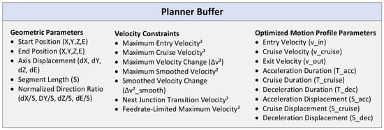
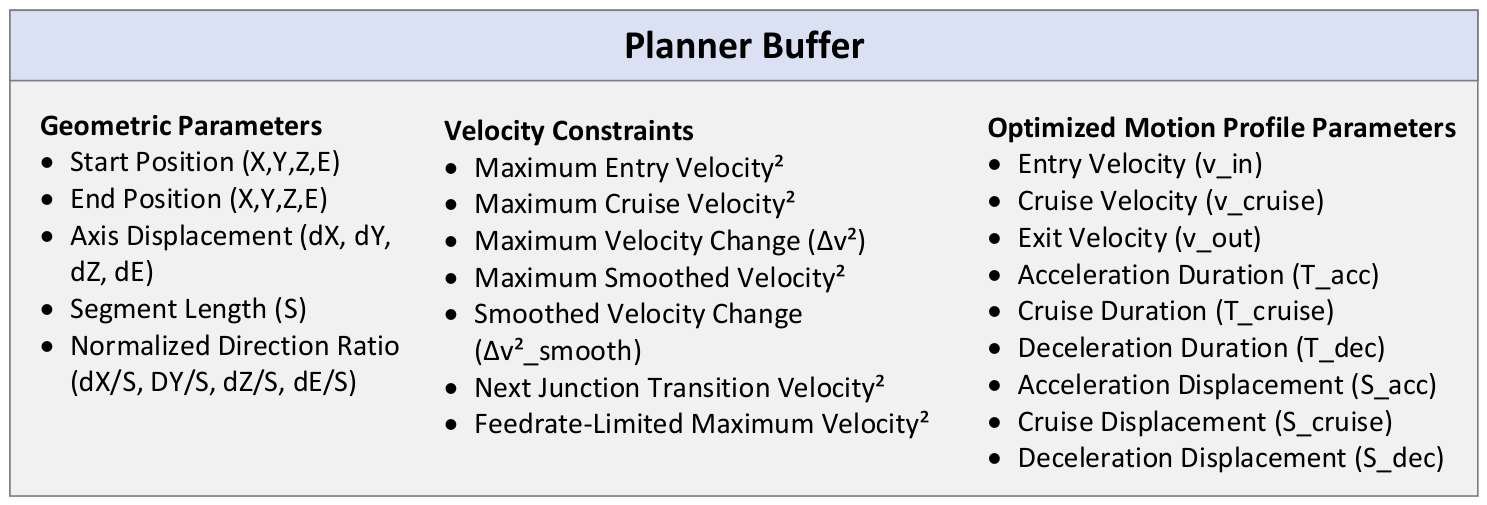
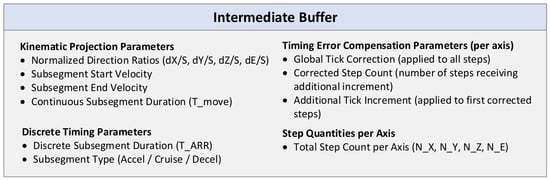
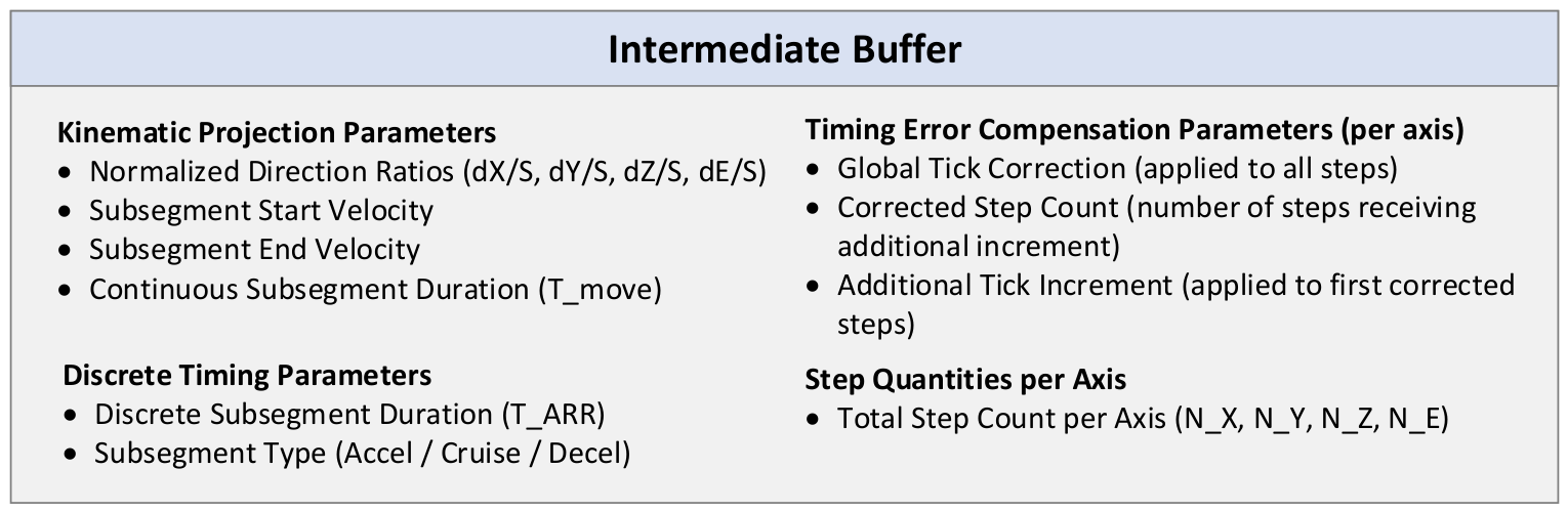
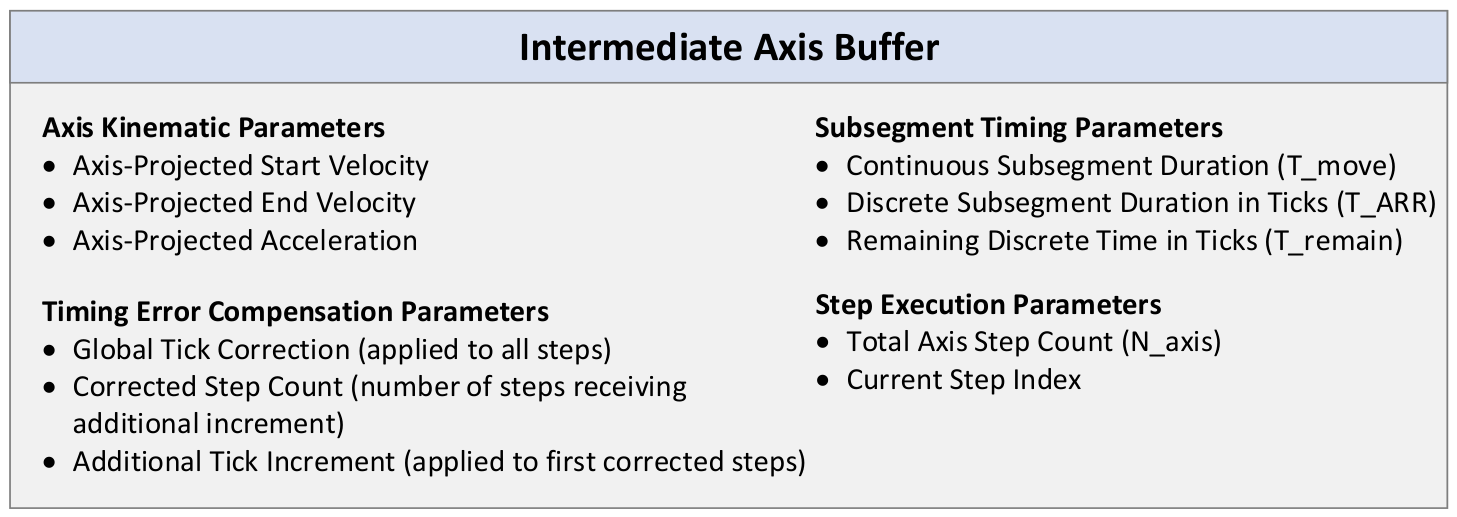
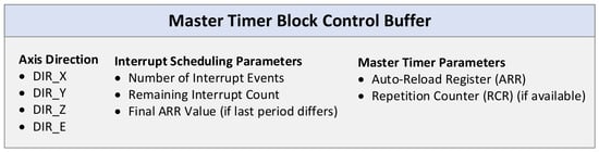
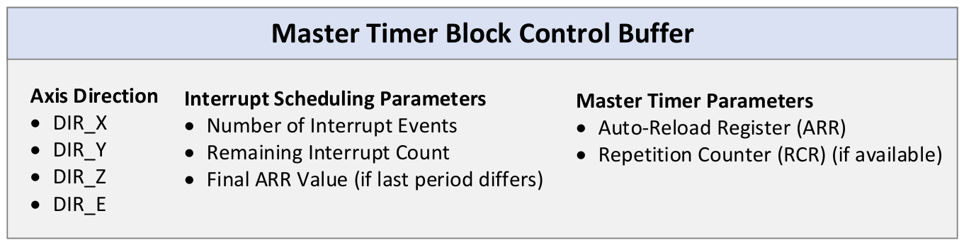
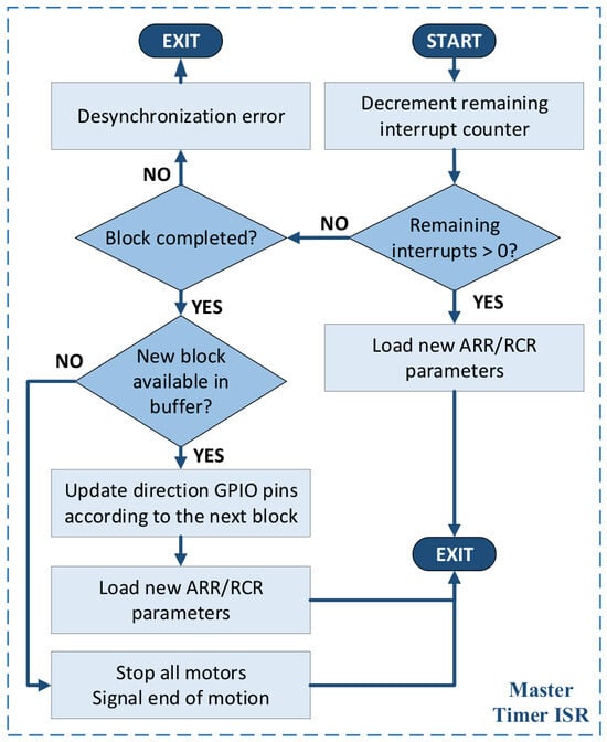
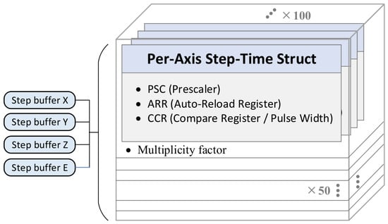
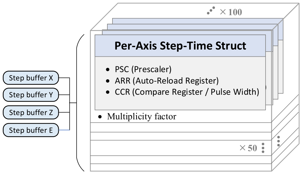
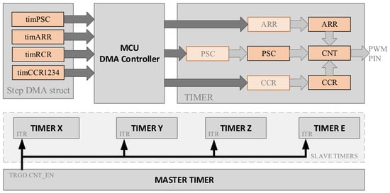
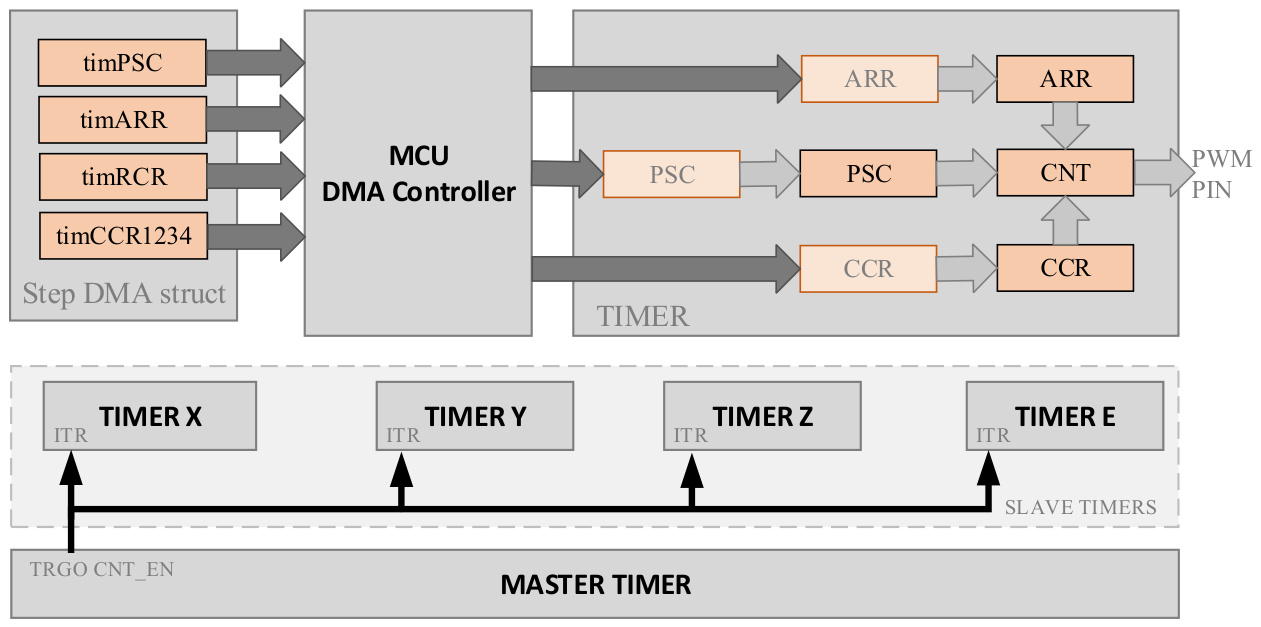
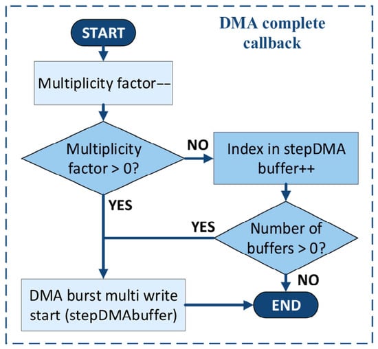
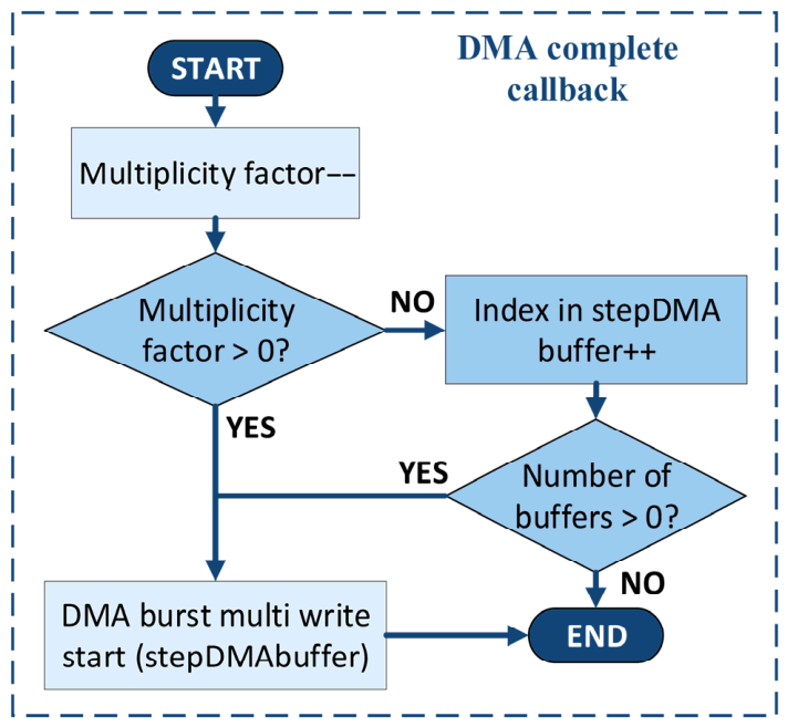
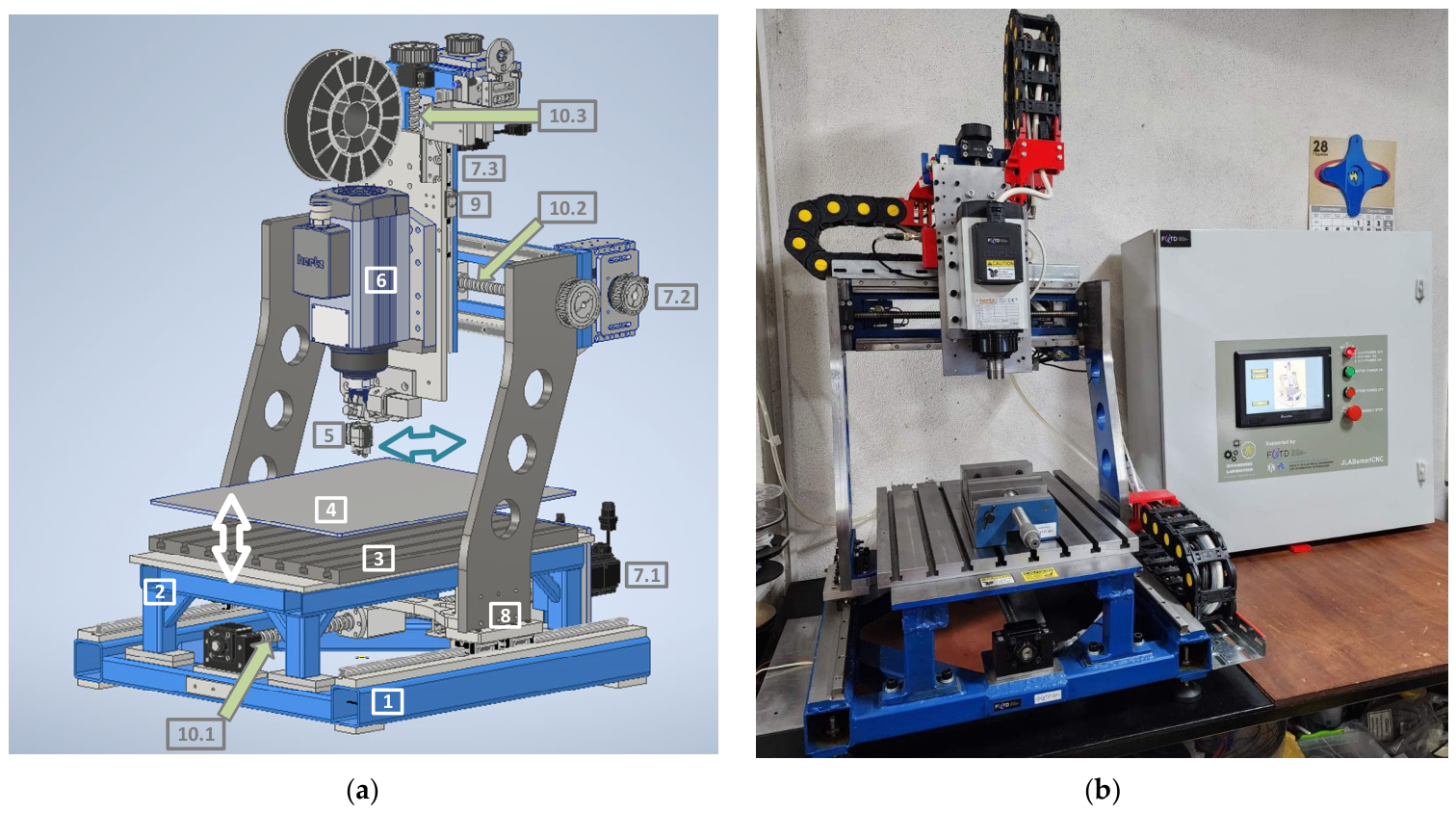
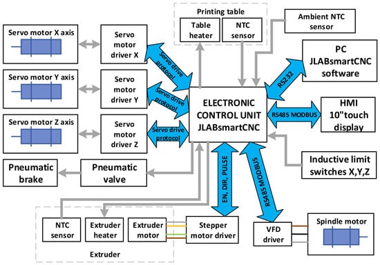
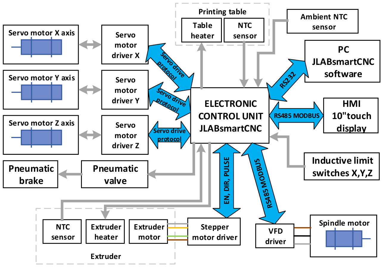
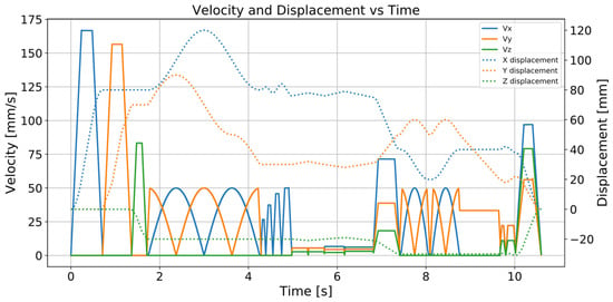
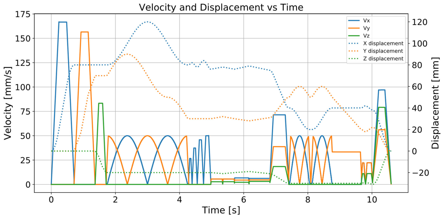
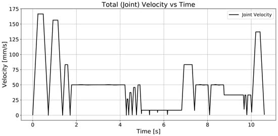
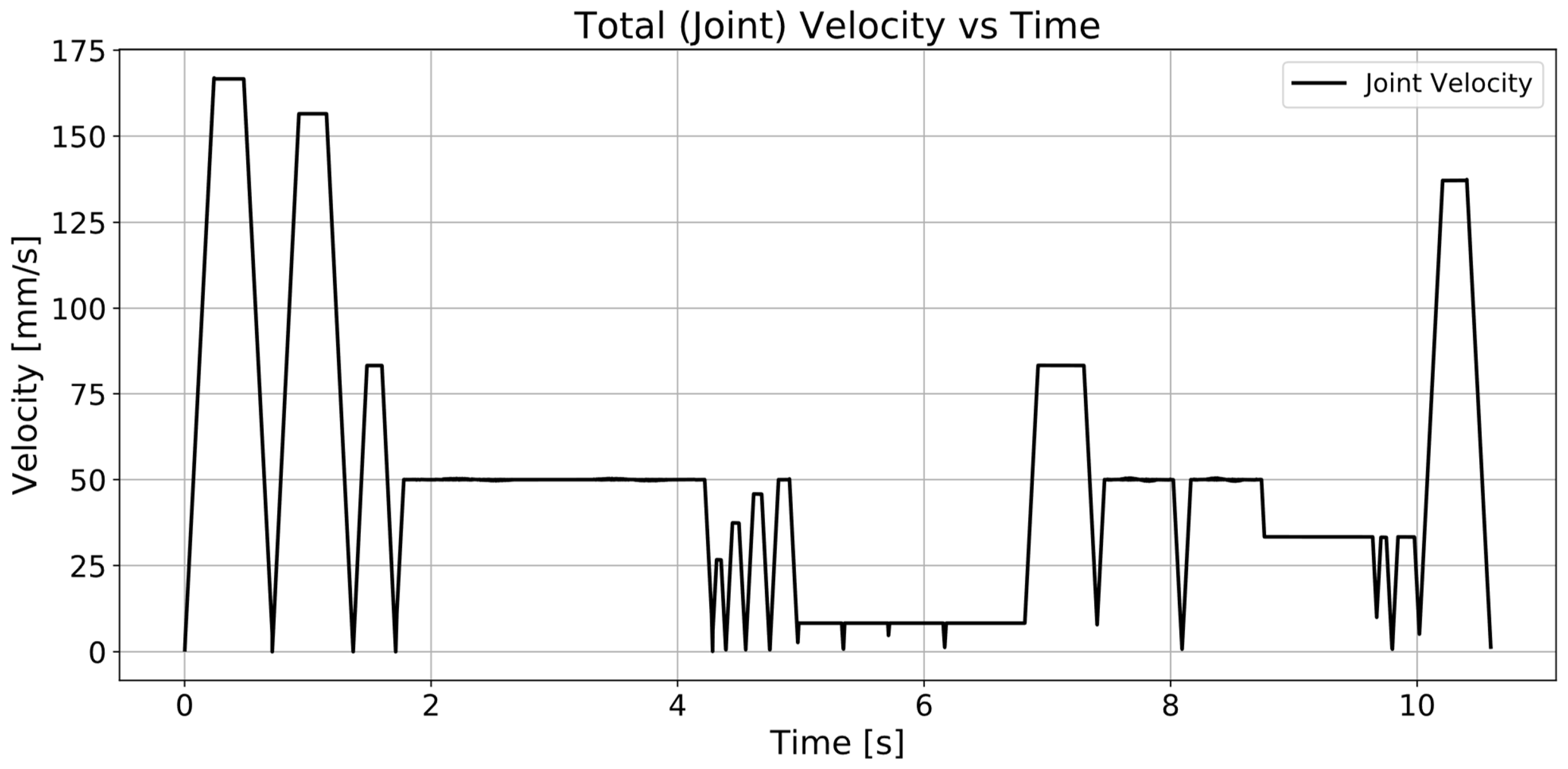
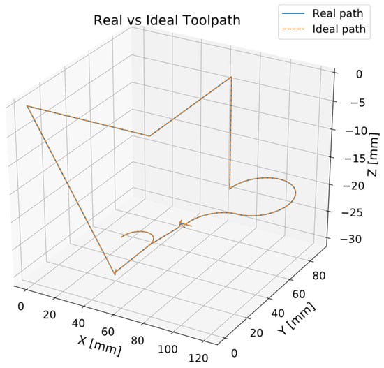
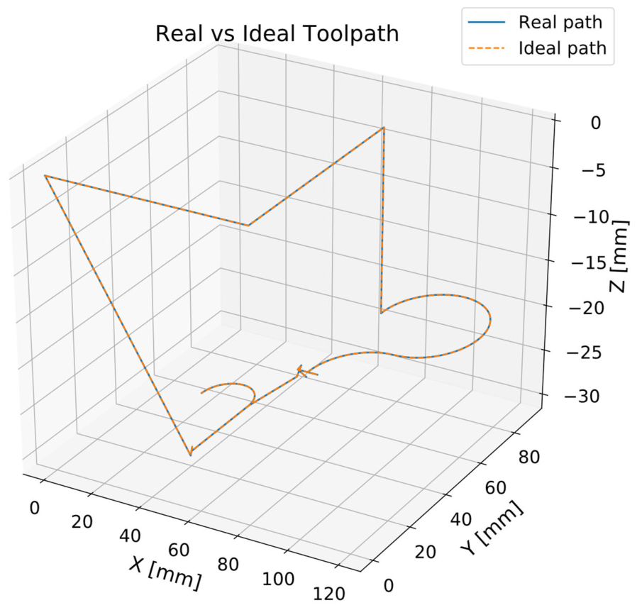
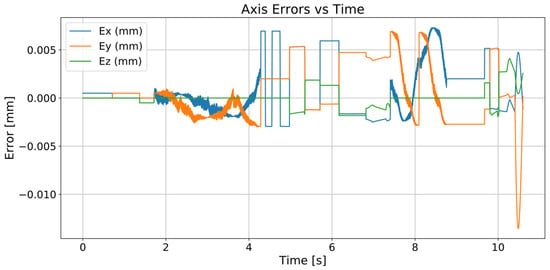
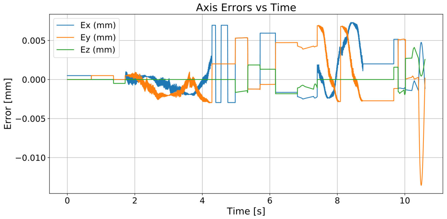
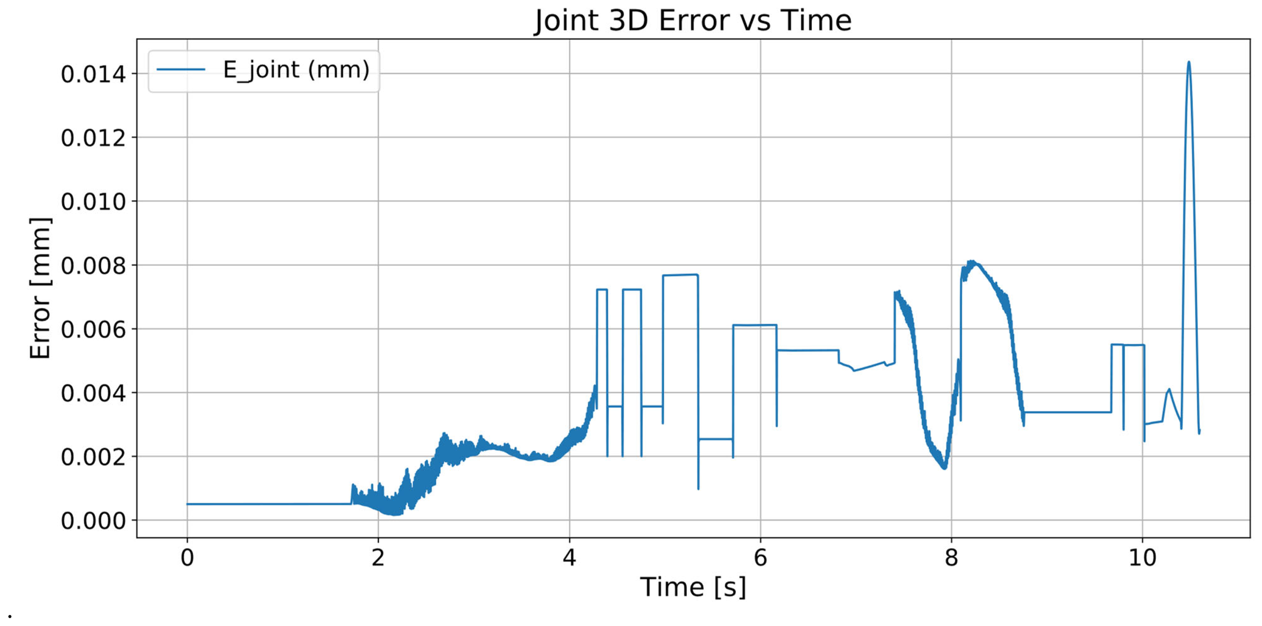
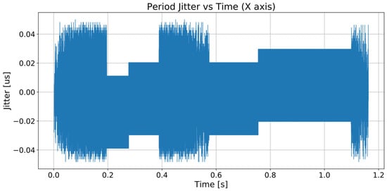
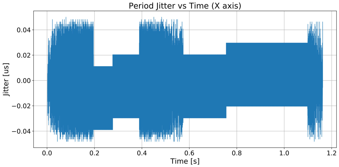
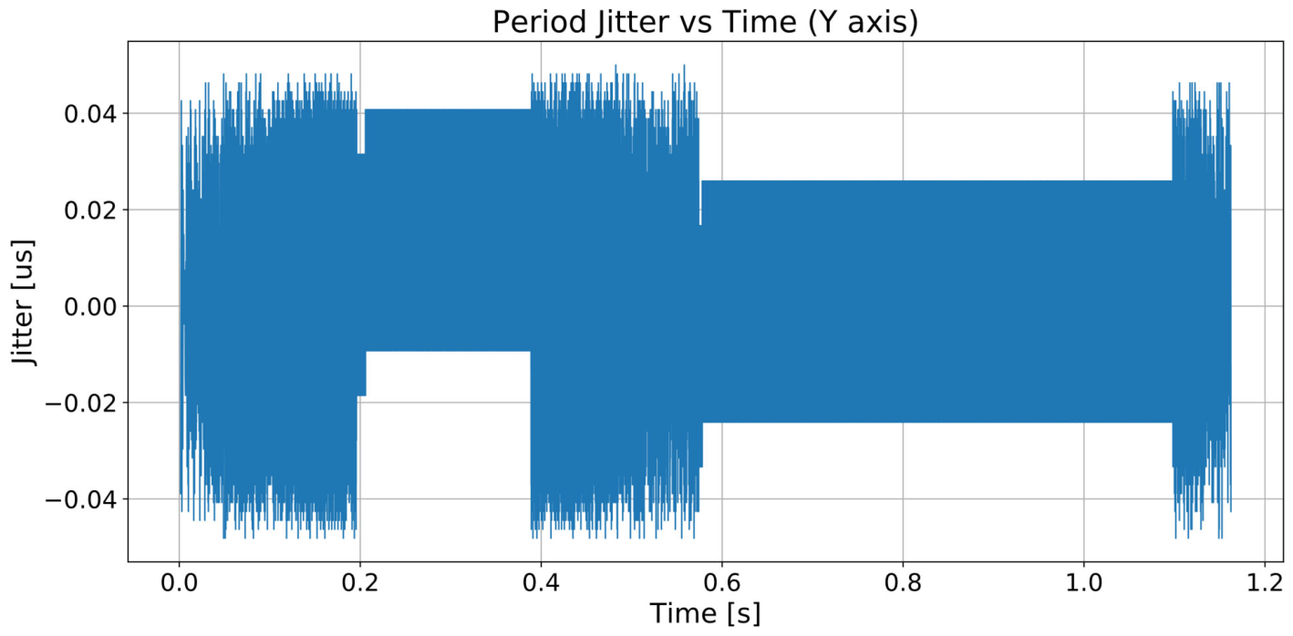
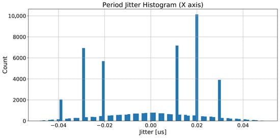
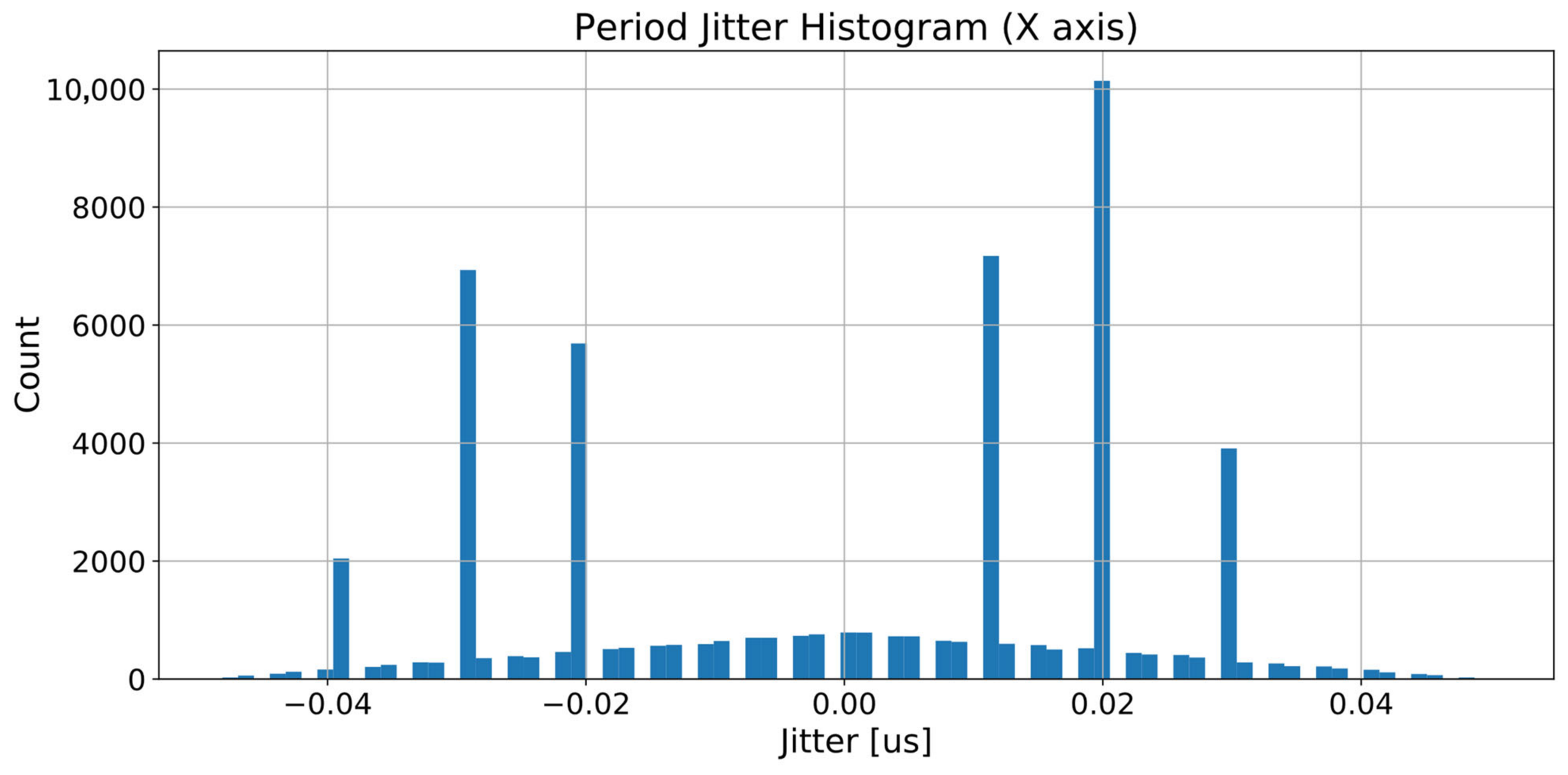
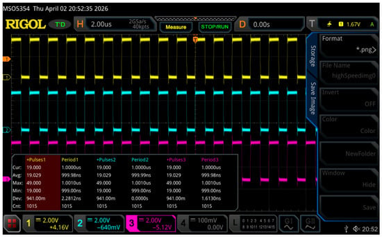
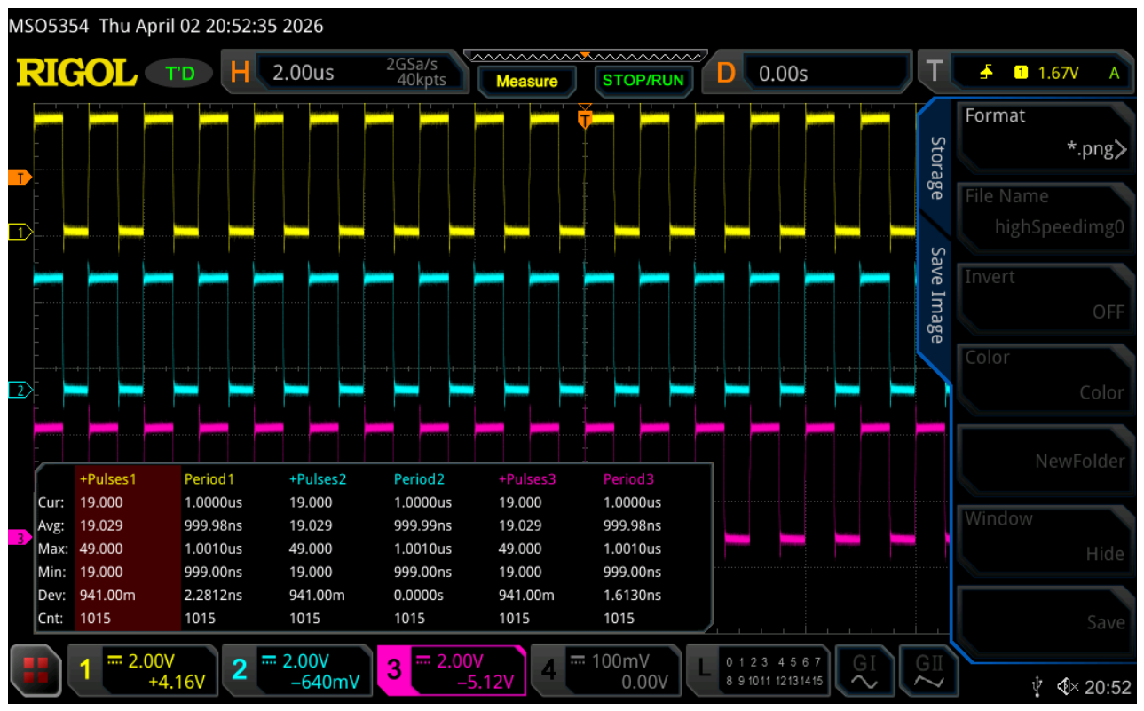
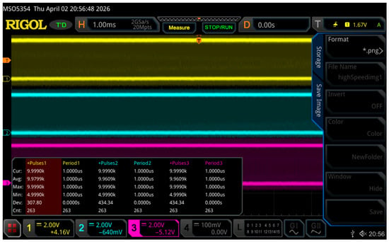
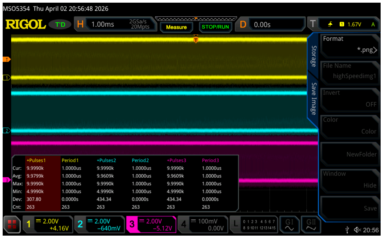
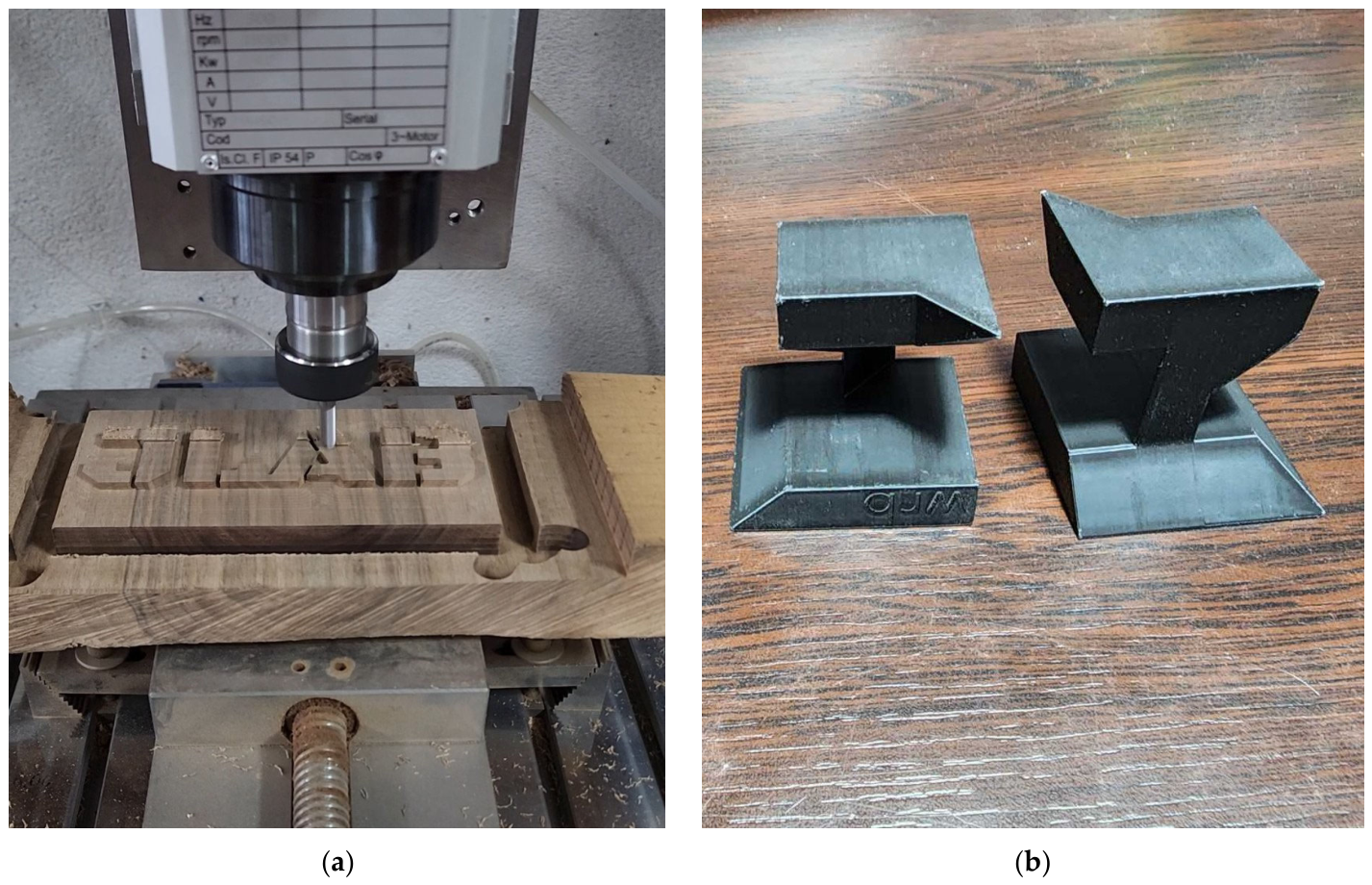

Disclaimer/Publisher’s Note: The statements, opinions and data contained in all publications are solely those of the individual author(s) and contributor(s) and not of MDPI and/or the editor(s). MDPI and/or the editor(s) disclaim responsibility for any injury to people or property resulting from any ideas, methods, instructions or products referred to in the content. |
© 2026 by the authors. Licensee MDPI, Basel, Switzerland. This article is an open access article distributed under the terms and conditions of the Creative Commons Attribution (CC BY) license.