


Abstract
Asymmetric Cascaded Multilevel Inverters (ACMLIs) have emerged as a prominent solution for medium- and high-power applications due to their ability to provide an increased number of output voltage levels with fewer power switches. However, maintaining low total harmonic distortion (THD) and ensuring robust stability under varying operating conditions remain significant challenges. This study experimentally validates a voltage-feedback Proportional-Resonant (PR) control strategy for a seven-level ACMLI. Unlike conventional current-feedback methods, the proposed approach directly regulates the output voltage, providing superior harmonic suppression and enhanced steady-state accuracy. The stability and dynamic performance of the controller were theoretically analyzed using Bode diagrams and root locus methods, and further verified through the MATLAB Curve Fitting Tool (CFT) with a high correlation (R2 = 0.9989). Experimental results demonstrate that the integration of the PR controller significantly improves power quality, reducing the current THD from 6.55% to 3.68% and the voltage THD to 2.94%. These findings confirm that the system fully complies with IEEE 519 standards and outperforms several existing strategies in the literature. The results establish the voltage-feedback PR control as a robust, high-precision, and practical alternative for power quality-oriented multilevel inverter applications in modern energy systems.
1. Introduction
Multilevel inverters (MLIs) have become a cornerstone in medium- and high-power applications, such as renewable energy integration and industrial motor drives, due to their ability to produce high-quality output voltage with reduced harmonic distortion and lower voltage stress on power switches [1,2].
Classic MLI structures are generally examined in three main categories: Diode Clamped (NPC), Flying Capacitor (FC), and Cascaded H-Bridge (CHB) [1,3]. Among these topologies, CHB inverters are widely preferred, particularly in applications with discrete DC sources such as photovoltaic systems and battery energy storage systems, due to their modular structure, fault tolerance capabilities, and flexibility in reaching high voltage levels [4,5]. Cascaded structures are further subdivided into two subclasses based on the size of the DC sources used: “Symmetric” structures, where all sources have the same voltage value, and “Asymmetric” structures, where the sources differ in certain ratios (two, three, etc.). In addition, Modular Multilevel Inverters for high-voltage applications and reduced-switch-count hybrid topologies, developed to reduce system costs, have also taken their place as separate classes in the literature in recent years [6,7]. Among various topologies, asymmetric cascaded multilevel inverters (ACMLIs) are particularly advantageous as they generate a higher number of output levels with fewer isolated DC sources and semiconductor components compared to symmetric configurations [8,9,10]. For instance, a seven-level output can be achieved using only two H-bridges with a 1:2 DC-link ratio, enhancing power density and reducing system costs [11,12,13,14,15,16].
Besides advancements in hardware topology, modulation and control strategies, which directly affect the performance of these inverters, are also extensively discussed in the literature. In addition to classical methods such as Sinusoidal Pulse Width Modulation (SPWM), Selective Harmonic Elimination (SHE-PWM) and Selective Harmonic Reduction techniques, which aim to minimize switching losses and harmonics, are frequently investigated [11,17].
Efficient operation of ACMLIs necessitates specialized modulation strategies to manage unequal DC-link voltages. While various carrier-based techniques like Level-Shifted PWM (LS-PWM) are common, this study utilizes the Phase Opposition Disposition (POD-SPWM) method for the seven-level ACMLI to optimize switching transitions and ensure compliance with the IEEE 519 harmonic standards. Such advanced modulation, when integrated with robust closed-loop control, is important for mitigating voltage steps and maintaining stability under varying load conditions [10,11].
Despite these advantages, the control of ACMLIs presents challenges, particularly in maintaining low Total Harmonic Distortion (THD) and ensuring stability under varying load conditions. Traditional Proportional-Integral (PI) controllers, while widely used in DC-AC conversion, exhibit inherent limitations in tracking sinusoidal references, resulting in steady-state phase and magnitude errors [18,19]. To address these limitations, Proportional-Resonant (PR) and Quasi-Proportional-Resonant (QPR) controllers have emerged as effective solutions, providing infinite or high gain at the resonant frequency to ensure zero steady-state error [20,21]. While ideal PR controllers offer infinite gain at the resonant frequency, quasi-proportional-resonant (QPR) structures are also discussed in the literature to provide enhanced frequency tolerance and seamless synchronization, particularly under non-linear loading and islanded operating modes [22]. However, for the fixed-frequency operation of the proposed seven-level ACMLI, the ideal PR structure was prioritized due to its superior tracking accuracy. To overcome the steady-state error and phase lag limitations of conventional PI controllers, PR control is utilized in this study. Operating directly in the stationary reference frame, the PR controller provides an infinite gain at the resonant frequency (ω0), ensuring precise tracking of sinusoidal references and effective disturbance rejection without the need for complex dq transformations [12,18]. The industrial relevance of PR control is further evidenced in large-scale applications, such as utility-interactive multilevel photovoltaic inverters, where harmonic impedance modeling is crucial for maintaining grid stability and ensuring precise power quality management [23].
The ideal PR controller is mathematically defined by the transfer function in Equation (1):
In the PR transfer function, Kp defines the system bandwidth and stability margins, while Kr regulates the gain magnitude at the resonant frequency (ω0). The ideal resonant structure is utilized to provide an infinite gain at the fundamental frequency, ensuring zero steady-state error between the reference and measured voltages. This high selective gain at ω0 allows the controller to effectively eliminate the dominant low-order harmonics identified in the open-loop analysis, thereby ensuring a high-quality sinusoidal output regardless of the load conditions [12,20,24].
The transfer function of the ideal PR controller, as given in Equation (1), provides an infinite gain at the resonant frequency (ω0), ensuring zero steady-state error for the selected harmonic components. However, this ideal structure is highly sensitive to frequency variations and can pose stability challenges in practical implementations. To enhance the robustness of the system against grid frequency fluctuations and to provide a controllable bandwidth, a non-ideal PR controller is frequently preferred in the literature [23,25]. The transfer function of the non-ideal PR controller is expressed in Equation (2):
where ωc represents the cut-off frequency or the bandwidth around the resonant frequency. By introducing ωc, the controller maintains a high but finite gain over a wider frequency range, which effectively stabilizes the system while preserving its harmonic rejection capability [23].
The systematic design of the resonant gain (Kr) in Equations (1) and (2) is crucial for achieving high selectivity at the fundamental and harmonic frequencies. In this study, Kr is determined based on the required steady-state error minimization and the defined bandwidth of the utilized seven-level ACMLI [23]. Theoretically, a higher Kr value increases the gain at the resonant frequency (ω0), which enhances harmonic rejection. However, the selection process follows a stability-constrained approach where Kr is tuned to provide maximum gain at target frequencies without reducing the Phase Margin (PM) below the critical stability threshold of the digital controller [23,26]. This tuning ensures that the implemented system maintains zero steady-state error while remaining robust against the phase shifts introduced by the power stage filters [27].
Extensive research has focused on the modulation and control of ACMLIs. Recent studies have explored advanced techniques such as Model Predictive Control (MPC) and Selective Harmonic Elimination (SHE) to improve the spectral quality of the output voltage [16,24]. However, many of these approaches involve high computational complexity or are sensitive to parameter variations. While PR control is a well-established method, its specific application in seven-level ACMLI structures—particularly the interaction between voltage-feedback loops and asymmetric DC-link ratios—requires further empirical validation [16,24].
This study addresses the gap by providing a comprehensive design and experimental validation of a voltage-feedback PR-controlled seven-level ACMLI. The main contributions of this study are as follows:
- A detailed analysis of the asymmetric seven-level topology and the implementation of a computationally efficient PR control law.
- Systematic tuning of the PR controller parameters to ensure stability and rapid dynamic response.
- A rigorous comparison between simulation results and hardware-in-the-loop experiments to verify the effectiveness of the control scheme under different operating conditions.
While current-feedback mechanisms dominate the literature for grid-tied systems, this study implements a voltage-feedback strategy to prioritize output voltage purity in stand-alone applications. This approach reduces hardware complexity and sensor costs by eliminating the need for current transducers. More importantly, voltage-feedback structures demonstrate superior resilience against measurement noise and maintain high-quality sinusoidal waveforms under non-linear or light-load conditions, where current-based controllers often suffer from parameter sensitivity [16,18]. Table 1 summarizes the comparative advantages of the utilized voltage-feedback scheme over conventional current-control methods.
Table 1.
Comparison of current-feedback and voltage-feedback structures.
Table 2.
Comparative analysis of recent literature on ACMLI control and harmonic performance.
Literature on MLI technologies primarily focuses on balancing high voltage quality with reduced switch counts to minimize THD. While symmetric CHB structures have been extensively evaluated for their modularity [11], recent research has shifted towards asymmetric configurations (ACMLI) to enhance power density using fewer components [6,17]. Advanced control strategies, including Model Predictive Control (MPC) and AI-based optimizations like ANN or PSO-Fuzzy hybrids, have demonstrated significant THD reductions, reaching levels below 2% [29,31]. However, the computational complexity of these methods often limits their practical industrial implementation. In contrast, Proportional-Resonant (PR) control offers a robust alternative by providing high gain at specific frequencies without the need for complex transformations [18]. Recent trends also highlight the use of Quasi-PR (QPR) controllers for improved stability in frequency-varying environments [28]. A summary of these comparative studies, focusing on topology, control method, and THD performance, is provided in Table 2.
While the aforementioned academic studies focus on specific control improvements, the industrial relevance of these topologies is further evidenced by existing commercial solutions. Table 3 summarizes key CHB architectures from leading global manufacturers, highlighting their DC link configurations and output characteristics to provide a clear benchmark for the practical applicability of the utilized seven-level ACMLI structure. Leading industrial manufacturers have integrated various cascaded H-bridge configurations, often utilizing multiple isolated DC links to achieve high-quality sinusoidal outputs. While industrial standards traditionally emphasize modularity with symmetrical ratios, the transition towards asymmetrical DC source configurations—similar to the implemented 1:2 ratios in this study—is increasingly recognized for its ability to maximize output voltage levels while minimizing the overall semiconductor count.
Table 3.
Comparative overview of commercial CHB solutions and industrial standards.
Traditional PI controllers are known to produce steady-state errors when tracking sinusoidal references in the stationary reference frame. In this study, a direct voltage-feedback PR control strategy was implemented to eliminate these errors and provide high-selective gain at the fundamental frequency. Unlike traditional dual-loop (current + voltage) control schemes that require multiple sensors and complex decoupling, this study achieves high dynamic performance using a single-loop voltage feedback, significantly reducing the implementation cost and computational burden without compromising stability.
Unlike traditional studies that focus on symmetric topologies or complex coordinate transformations, this study proposes a computationally efficient single-loop voltage-feedback PR control specifically optimized for a seven-level asymmetric (1:2 DC-link ratio) architecture. The main contribution lies in achieving high-order harmonic suppression (up to the ninth harmonic) without an inner current loop, thereby reducing hardware complexity and sensor costs while maintaining full compliance with IEEE 519 standards under both steady-state and dynamic step-load conditions. Furthermore, the experimental validation on a real-time hardware prototype demonstrates the practical feasibility of the proposed control strategy in bridging the gap between theoretical modeling and industrial applications.
The remainder of this paper is structured as follows: Section 2 describes the asymmetric CHB topology and the discrete modulation scheme; Section 3 details the PR controller design, stability verification via Bode diagram and Root Locus analyses, and the configuration of the experimental setup; Section 4 presents a comprehensive evaluation of the simulation and experimental results, supported by statistical validation using the Curve Fitting Tool (CFT); and finally, Section 5 provides the concluding remarks and future research directions.
2. Modeling and Control of the ACMLI
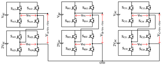
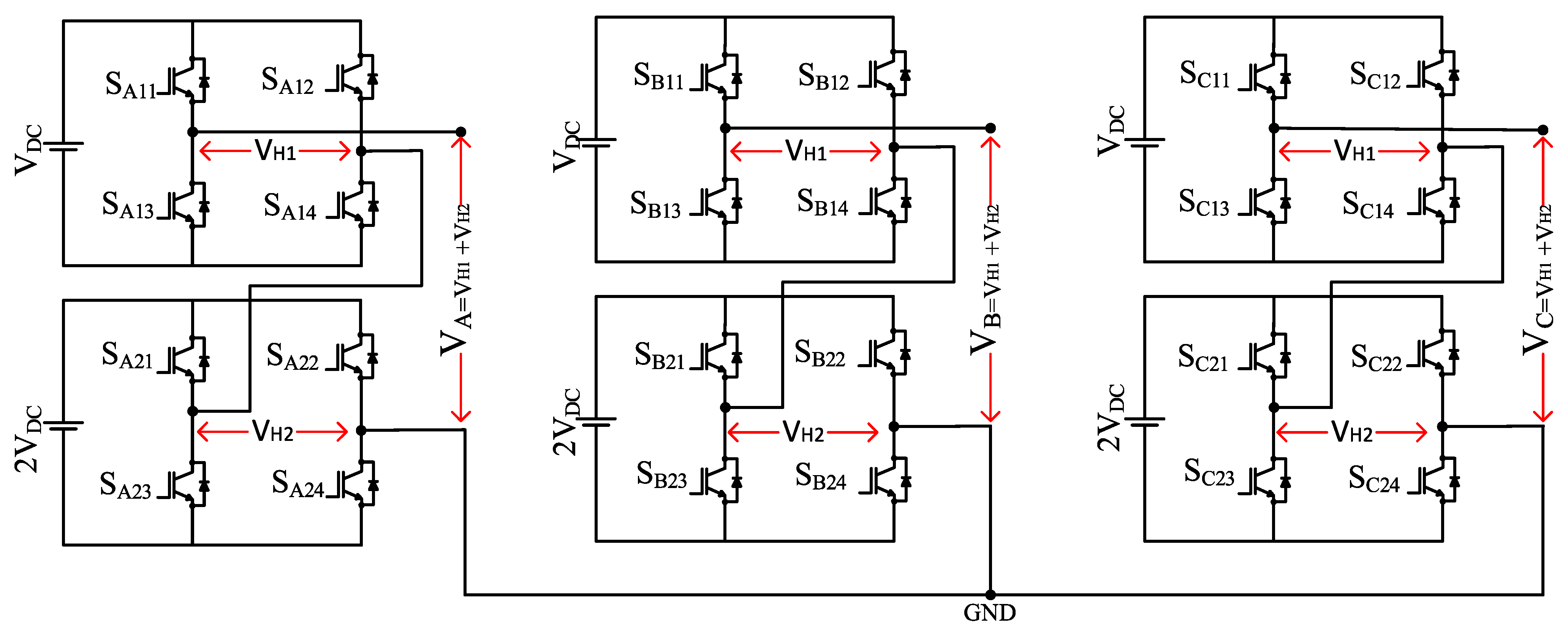
In this study, a seven-level three-phase inverter has been designed for the implementation of the ACMLI, which includes H-Bridge Cells. To analyze the operation of the ACMLI structure, preliminary simulation studies were conducted. The connection of the seven-level ACMLI switching elements used in these simulations is configured as illustrated in Figure 1. In this configuration, the upper switches are subjected to low voltage, whereas the lower switches are subjected to high voltage. Each phase utilizes two H-bridge cells, incorporating 8 switching elements per phase, resulting in a total of 24 switching elements for the entire system. Also, in a seven-level inverter where the input voltage values are VDC and 2VDC, the output voltage can assume the discrete values of 3 VDC, 2 VDC, VDC, 0, −VDC, −2 VDC, and −3 VDC.
Figure 1.
Topology of the 7-level ACMLI with 1:2 DC-link voltage ratio.
The seven-level ACMLI topology used is particularly well-suited for islanded operation, where independent DC energy sources such as photovoltaic panels or battery strings are commonly available. By employing an asymmetric 1:2 ratio for the DC-link voltages, the system produces a higher number of output levels with a reduced count of power components and isolated DC stages. Specifically, the seven-level output is achieved using only two H-bridge cells, providing a more compact and cost-effective solution compared to the three-cell symmetric counterpart. This configuration not only simplifies the power stage but also allows for independent energy management of each DC source, which is critical for maintaining power quality in off-grid microgrid applications.
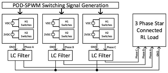
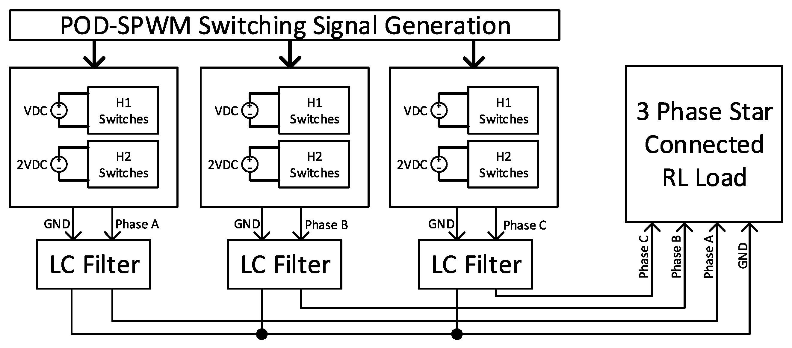
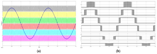
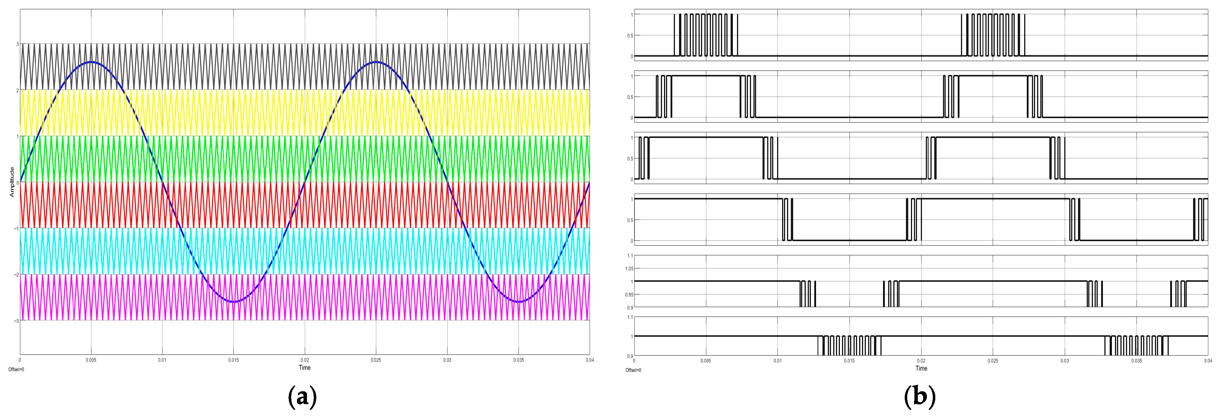
The seven-level ACMLI was initially modeled to evaluate its performance under POD-SPWM, which was previously identified as the optimal switching strategy for this topology [33]. The comprehensive control architecture is illustrated in the block diagram in Figure 2. Within this framework, the POD-SPWM block manages the switching transitions by comparing a sinusoidal reference signal with six level-shifted triangular carriers. As shown in Figure 3a, these carrier signals are distributed across distinct voltage levels, while the reference signals for each phase are maintained with a 120° phase shift to ensure balanced operation.
Figure 2.
Block of simulation for 3-phase 7-level ACMLI with POD-SPWM.
Figure 3.
POD-SPWM switching signal generation: (a) sine-triangle comparison operation; (b) signals obtained from sine-triangle comparison.
The resulting pulse-width modulated (PWM) signals are depicted in Figure 3b. To generate the specific seven-level output required by the asymmetric configuration, the switching sequences for the low-voltage H-bridge units are derived using an XOR-based logic combination of the primary comparison signals. The detailed simulation parameters and component specifications are summarized in Table 4.
Table 4.
Seven-level ACMLI simulation parameters under open-loop and closed-loop conditions.
The LC filter parameters are strategically selected to provide sufficient attenuation of high-frequency switching components while maintaining system stability. The resonance frequency (fres) of the LC filter is calculated in Equation (3).
When the filter parameters given in Table 4 are calculated according to Equation (3), the resonance filter value is calculated to be approximately 459.44 Hz. This resonance frequency is located well above the fundamental frequency (50 Hz) and significantly below the effective switching frequency of the multilevel inverter. Due to the high-order nature of the seven-level output and the precise frequency-selective gain provided by the PR controller at the fundamental frequency, the system exhibits inherent stability. The inherent passive damping provided by the internal resistance of the filter inductor and the capacitor’s ESR is sufficient to prevent oscillations at fres. Consequently, the implementation of additional active damping control was deemed unnecessary, thereby reducing the computational overhead on the digital controller.
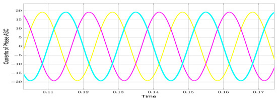
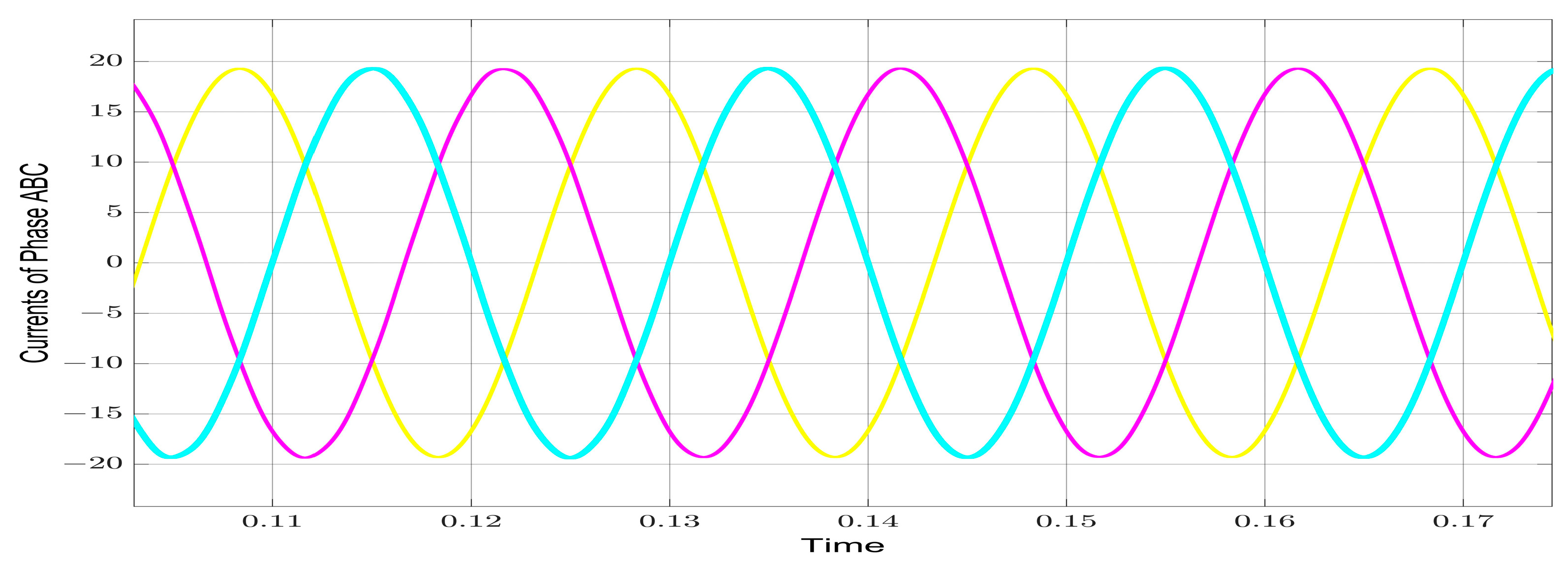
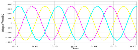
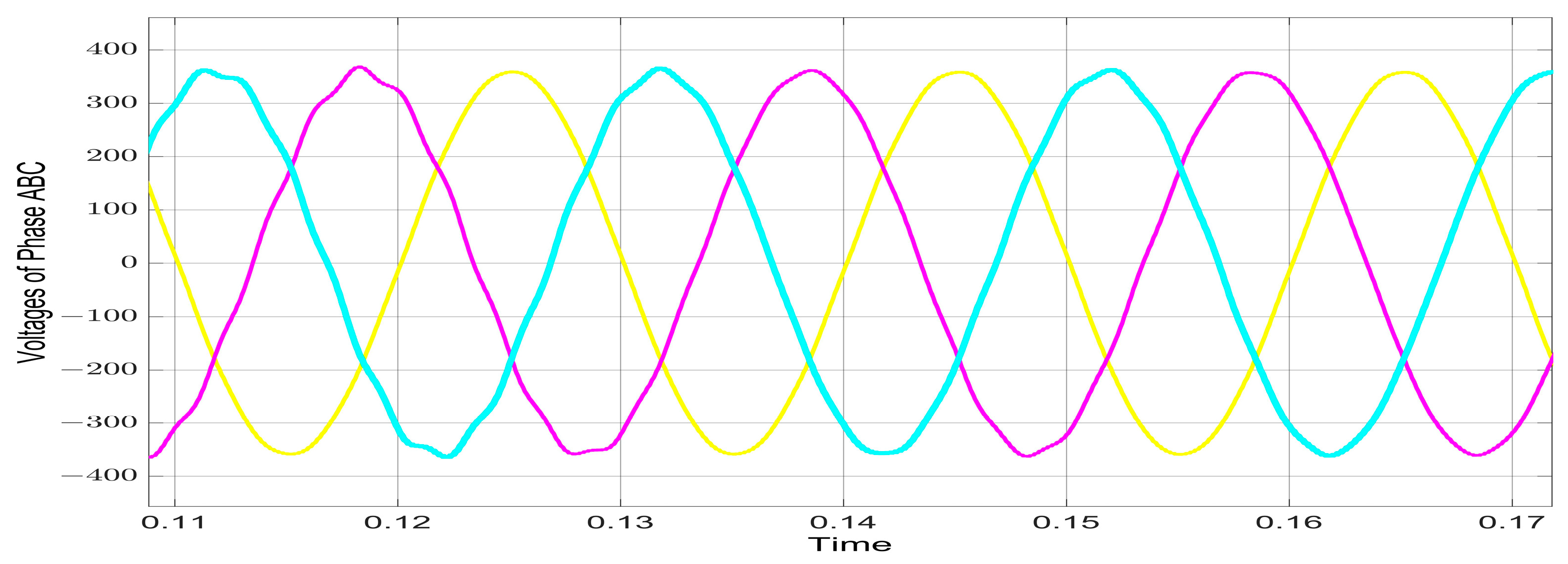
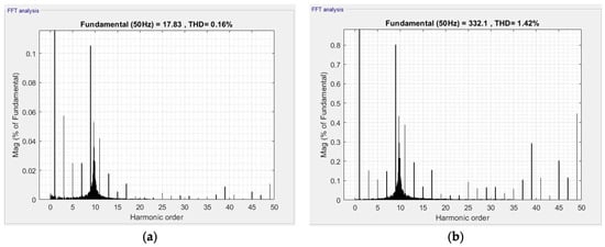
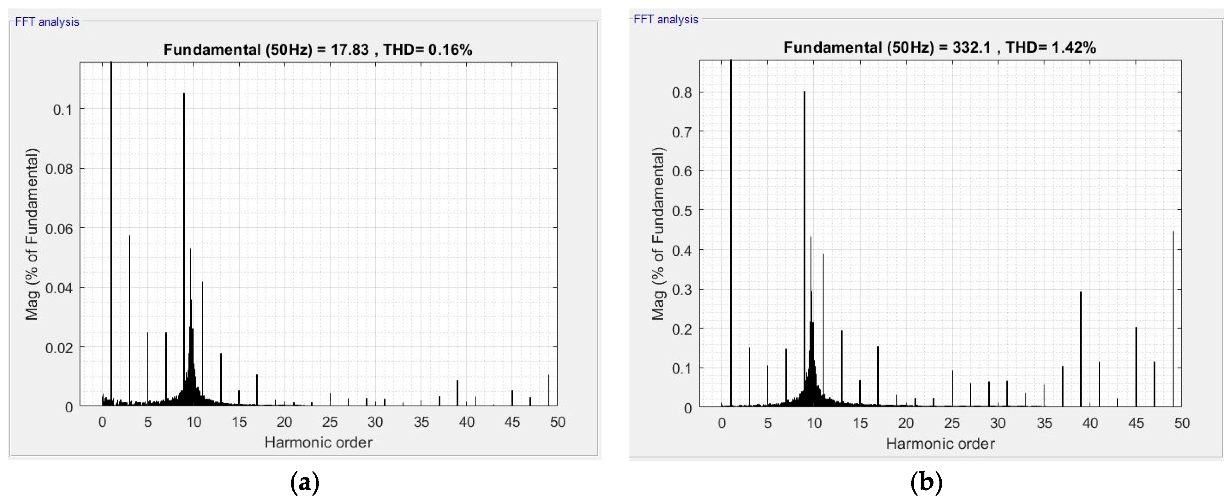
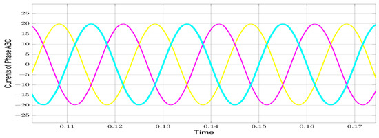
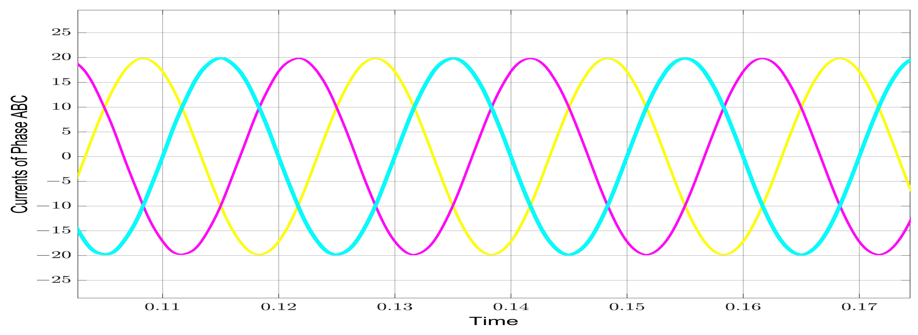
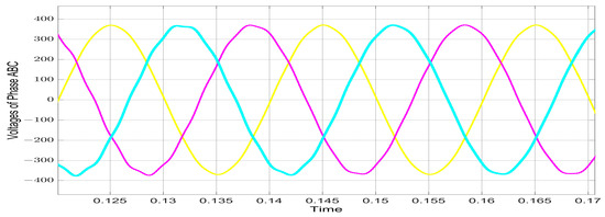
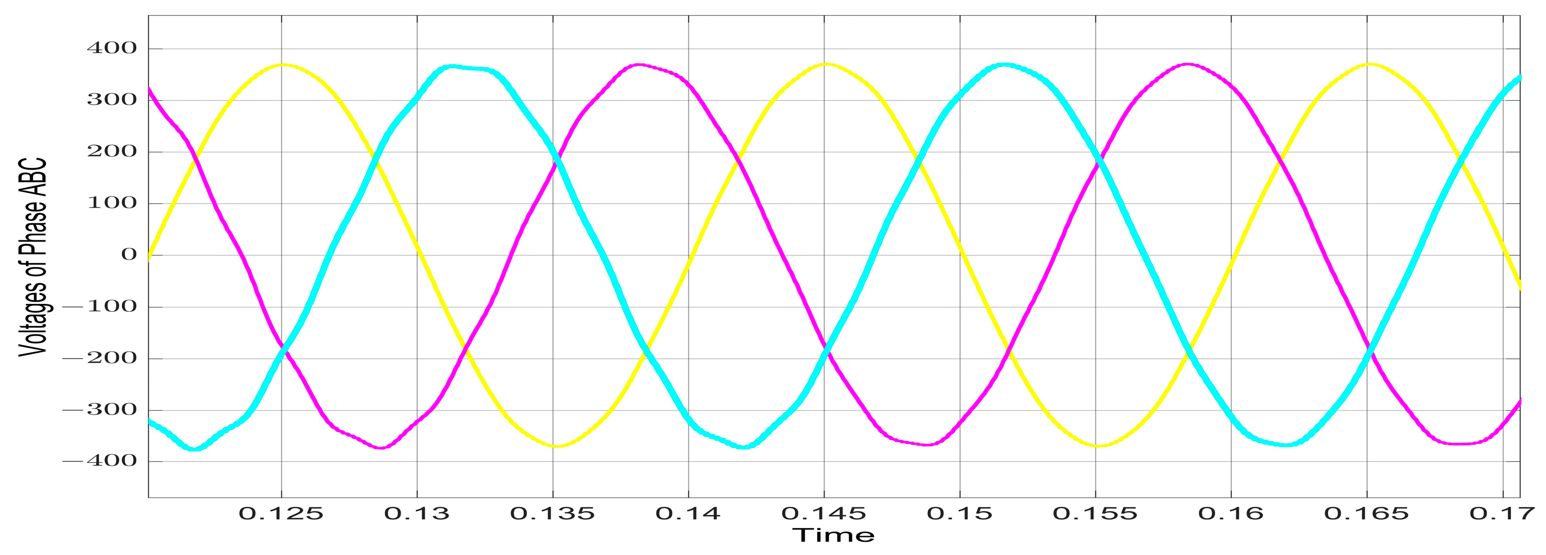
The open-loop performance of the three-phase seven-level ACMLI was evaluated using POD-SPWM to establish a baseline for the control strategy. The resulting output phase currents and the seven-level output phase voltages are illustrated in Figure 4 and Figure 5, respectively. In this uncompensated operating mode, the harmonic performance was analyzed as shown in Figure 6, where the THD values were measured as 0.16% for current (THDi) and 1.42% for voltage (THDv). With the input DC sources set at 150 V and 300 V, the output phase voltage reached an RMS value of 234 V and a peak-to-peak (Vp−p) value of 717 V, while the load current was recorded at 18.9 A.
Figure 4.
Output current waveforms of 3-phase 7-level ACMLI under open-loop control.
Figure 5.
Output voltage waveforms of 3-phase 7-level ACMLI under open-loop control.
Figure 6.
THD values of phase A in 7-level ACMLI under open-loop control: (a) THDi, (b) THDv.
The detailed harmonic decomposition of the output current under open-loop operation is illustrated in Figure 6a. Although the overall THDi is recorded at 0.16%, a closer inspection of the harmonic spectrum reveals that specific low-order components are particularly prominent. The third, fifth, seventh, and ninth harmonics exhibit magnitudes of 0.056%, 0.025%, 0.025%, and 0.105% relative to the fundamental component, respectively. Similarly, the harmonic analysis of the output phase voltage under open-loop conditions is presented in Figure 6b. While the THDv is measured at 1.42%, the impact of specific low-order harmonics is more pronounced in the voltage spectrum compared to the current. The magnitudes of the third, fifth, seventh, and ninth voltage harmonics are recorded as 0.16%, 0.105%, 0.15%, and 0.801% of the fundamental component, respectively. Although these values remain within the general limits of international standards for open-loop operation, the presence of these uncompensated components confirms the necessity of a closed-loop voltage-feedback strategy.
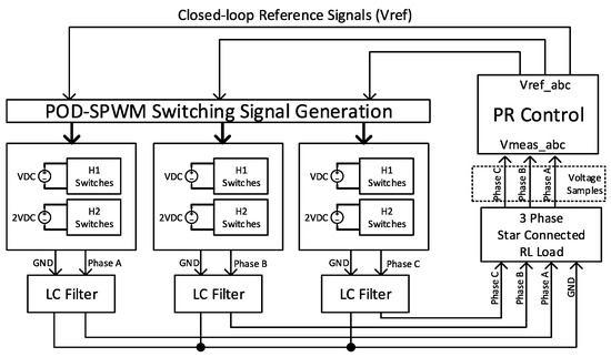
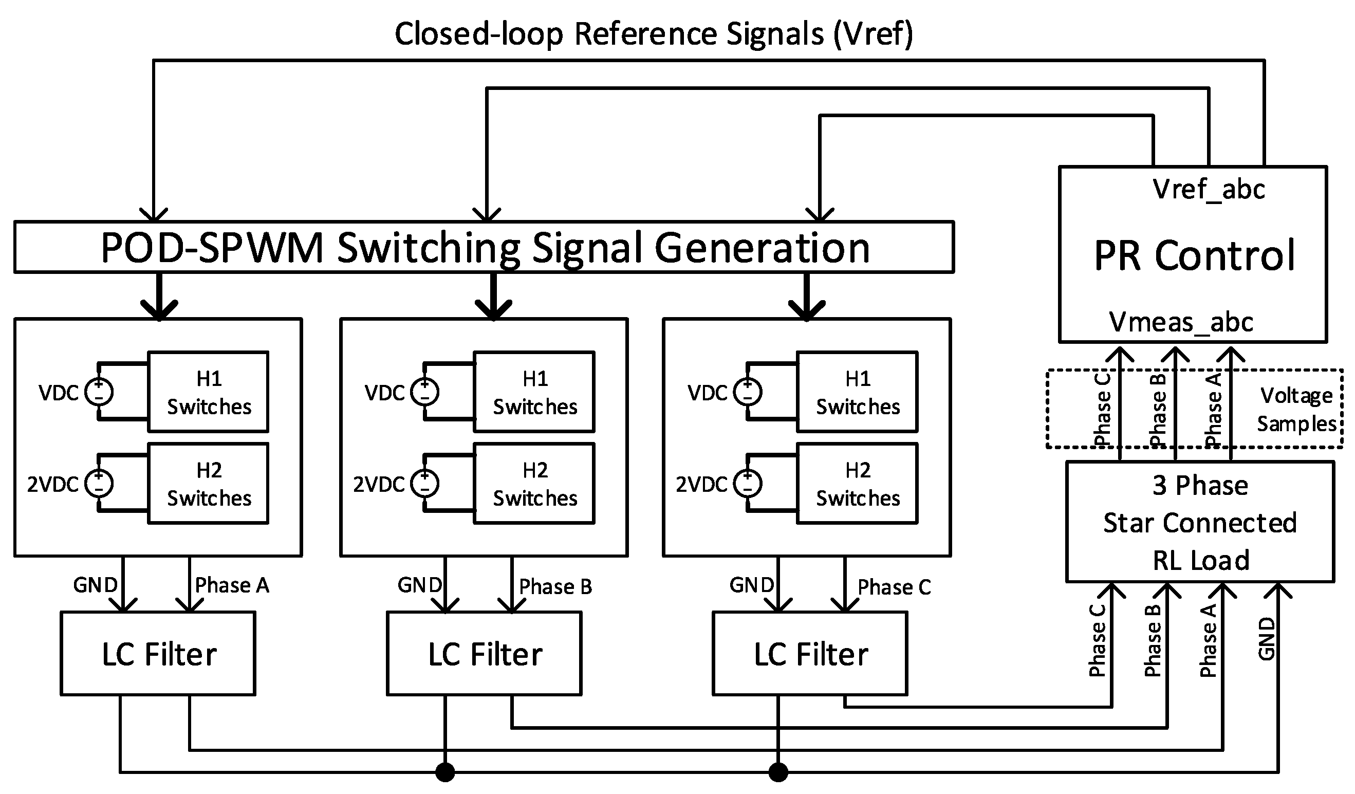
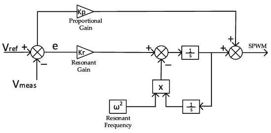
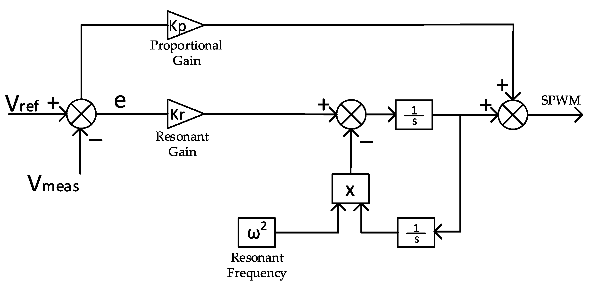
To overcome the limitations of the open-loop configuration and further suppress the specific low-order harmonics identified in the previous section, a closed-loop voltage-feedback PR control scheme is integrated into the modulation framework. The comprehensive architecture of the PR-controlled POD-SPWM system is illustrated in Figure 7. In this closed-loop structure, the output voltage is sensed and compared with a sinusoidal reference to generate an error signal, which is then processed by the PR controller to ensure zero steady-state error at the fundamental frequency. The internal mathematical structure of the resonant compensator, designed to provide high selective gain while maintaining system stability through ideal resonant controller formulation, is depicted in Figure 8. To ensure a valid performance comparison, the filter components and load parameters remain identical to those utilized in the uncompensated simulation, as previously specified in Table 4.
Figure 7.
Closed-loop control scheme of the 3-phase 7-level ACMLI, integrated with voltage-feedback PR control and POD-SPWM.
Figure 8.
Detailed internal control structure of the voltage-feedback PR controller.
To ensure hardware compatibility during the experimental validation stage, the output voltage is attenuated by a scale factor of 1/100 before being processed by the control block. The internal structure of the PR controller, illustrated in Figure 8 for a single phase, is applied identically to each phase of the three-phase system on a per-phase basis. Within this architecture, the proportional gain (Kp) directly influences the modulation index of the POD-SPWM scheme. To maintain the reference sinusoidal voltage at a standard level of 3 V (peak), the Kp value is selected close to unity (Kp ≈ 1). The optimization of the controller parameters was conducted through an iterative simulation process; initially, the resonant gain (Kr) was kept constant to identify the optimal Kp, followed by a systematic evaluation of various Kr values. The primary objective of this tuning process was to minimize the THD for both output current and voltage while ensuring system stability.
In the simulation environment, the ideal PR controller model was utilized to evaluate the theoretical maximum performance of the implemented seven-level ACMLI and its ideal harmonic suppression limits. Since the simulation platform provides an environment free from hardware-induced delays and numerical precision limits, the ideal form serves as a benchmark for the controller’s resonance capability.
The selection of the controller parameters was based on a comprehensive sensitivity analysis to ensure both system stability and high harmonic mitigation performance. During the tuning process, the system was evaluated across a range of Kp and Kr values. It was observed that the output sinusoidal waveform experienced significant distortion when the proportional gain was set below 0.75 or above 1.0. Comparative tests were conducted for Kp values of 0.75, 0.8, 0.9, and 1.0, where Kp = 0.9 was identified as the optimal value for maintaining modulation integrity. Similarly, the resonant gain was analyzed at levels of 0.0001, 0.01, 1, and 10. The results indicated that Kr = 0.01 provided the most effective suppression of low-order harmonics while preventing resonance-induced oscillations.
Consequently, these optimized parameters (Kp = 0.9, Kr = 0.01) were utilized for the final performance evaluation. The steady-state performance of the three-phase seven-level ACMLI under these optimized conditions is illustrated in the following figures:
- Figure 9 presents the balanced three-phase output current waveforms, demonstrating the high-quality sinusoidal reconstruction achieved by the PR controller.
- Figure 10 shows the corresponding seven-level output phase voltages, confirming the stable operation of the asymmetric cascaded topology.
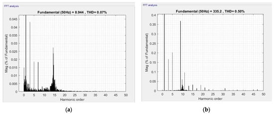
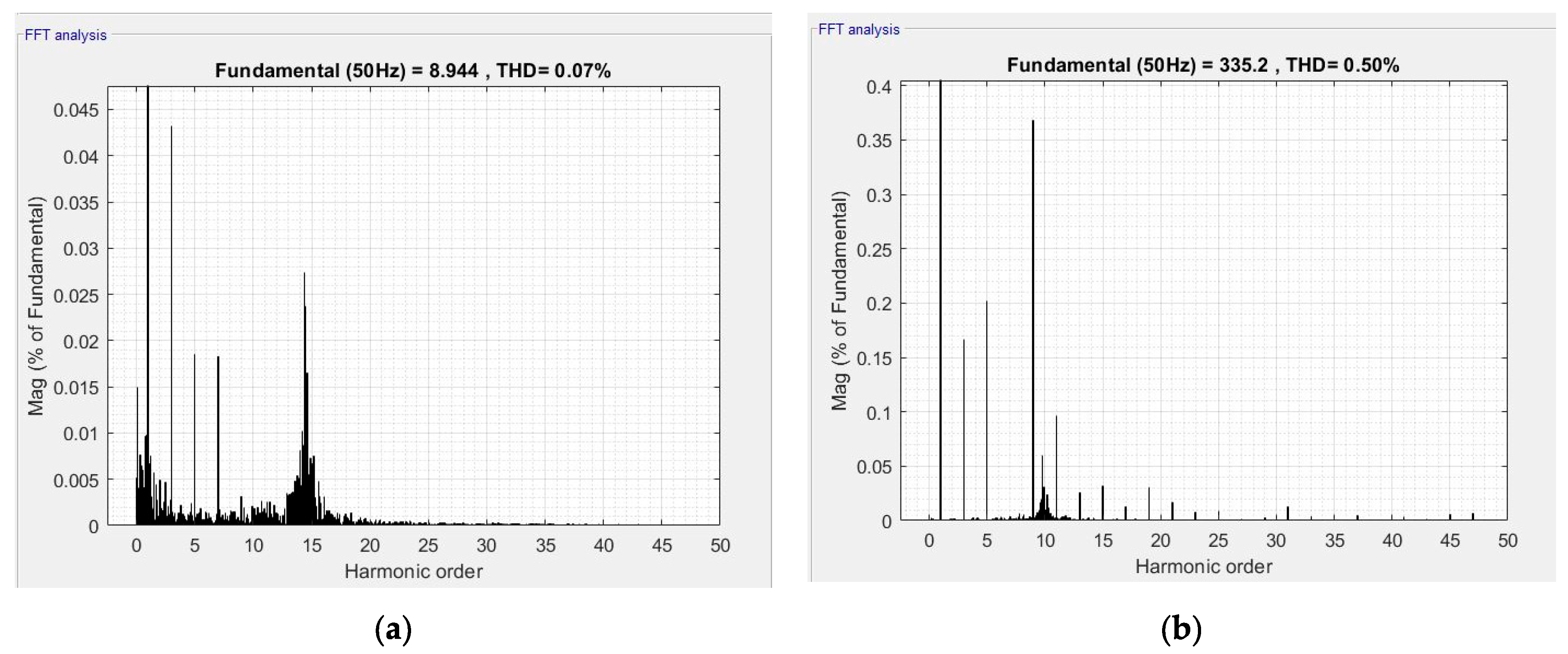
- Figure 11a,b provide the detailed FFT analysis for the output current and voltage, respectively.
Figure 9.
Waveforms of output current for Kp = 0.9 and Kr = 0.01 in simulation of PR controlled ACMLI using POD-SPWM technique.
Figure 10.
Waveforms of output voltage for Kp = 0.9 and Kr = 0.01 in simulation of PR controlled ACMLI using POD-SPWM technique.
Figure 11.
FFT analysis and harmonic spectrum of the output waves under PR control (parameters for Kp = 0.9 and Kr = 0.01). (a) Output current THDi = 0.07%. (b) Output voltage THDv = 0.50%.
Under these optimized conditions (Kp = 0.9, Kr = 0.01), the THDi of the output current was significantly reduced to 0.07%, while the THDv reached a superior level of 0.5%. A comparative analysis confirms the exceptional effectiveness of the Kr gain in suppressing low-order harmonics for both current and voltage. Specifically, for the output current, the ninth harmonic was suppressed to an almost negligible level of 0.003%, while the third, fifth, and seventh harmonics were mitigated to 0.043%, 0.0185%, and 0.0180%, respectively.
Similarly, the harmonic components of the output voltage exhibited significant improvement; the third, fifth, seventh, and ninth voltage harmonics were recorded at 0.165%, 0.203%, 0.001%, and 0.369%, respectively. The achievement of a 0.001% magnitude for the seventh voltage harmonic underscores the high resonance precision of the control architecture. Data from suboptimal configurations were excluded to maintain the focus on the high-performance control scheme and its ability to meet stringent power quality standards.
A comparative assessment between the theoretical harmonic distribution and the measured spectra in Figure 11 confirms the high precision of the utilized control strategy. The harmonic components observed in the high-frequency range are strictly aligned with the sidebands of the switching frequency and its multiples, which is a characteristic of the POD-SPWM technique. Specifically, the dominant clusters around the switching frequency validate that the implemented seven-level ACMLI topology effectively shifts the harmonic energy to higher frequencies, where they are easily attenuated by the output filter. This spectral distribution proves that the utilized PR controller maintains the low-order harmonics at nearly zero levels in the simulation environment, as expected from the ideal theoretical model.
The comparative performance analysis of the three-phase seven-level ACMLI under open-loop and closed-loop PR control is summarized in Table 5. The data clearly demonstrate that the integration of the voltage-feedback PR controller significantly improves the power quality of both the output current and voltage.
Table 5.
Comparative harmonic analysis of output current and voltage for open-loop and PR-controlled seven-level ACMLI.
Specifically, the THDi was reduced from 0.16% to 0.07%, while the THDv experienced a substantial decrease from 1.42% to 0.50%. A key observation from the table is the exceptional suppression of the seventh voltage harmonic, which reached a near-zero level of 0.001%, and the ninth current harmonic, which was mitigated to 0.003%. While most harmonic orders showed a consistent downward trend, the ninth voltage harmonic exhibited a slight increase (from 0.24% to 0.369%) due to the inherent interaction between the PR controller’s gain at the fundamental frequency and the modulation index, though it remained well within the limits of IEEE standards. Overall, these numerical results validate the effectiveness of the optimized Kp and Kr parameters in achieving superior waveform purity.
To verify the closed-loop stability and frequency response of the system, a frequency-domain analysis was conducted using the Bode plot illustrated in Figure 12. The analysis was performed with the optimized controller parameters (Kp = 0.9 and Kr = 0.01) for the ideal PR transfer function.
Figure 12.
Bode plot analysis of the ideal PR controller illustrating the magnitude and phase response for stability verification (Pm = 90°, Gm = Inf).
As shown in the magnitude plot, the controller exhibits an infinite gain peak precisely at the resonant frequency (fo = 50 Hz or ωo ≈ 314.16 rad/s), which ensures that the steady-state error is eliminated for the sinusoidal reference. The phase response indicates a Phase Margin (PM) of 90° at the gain crossover frequency, and the Gain Margin (GM) is identified as infinite (Inf dB). These stability margins confirm that the system is robustly stable and possesses an adequate damping characteristic to handle transients. Furthermore, the high-frequency gain remains sufficiently low to avoid the amplification of switching noise, validating the suitability of the selected Kp and Kr values for high-performance inverter control.
The Bode plot presented in Figure 12 represents the frequency response of the ideal PR controller used during the simulation phase. This ideal model is utilized to define the theoretical performance limits and to achieve near-zero steady-state error in a controlled environment. However, for the real-time implementation discussed in the next section, the digital controller inherently exhibits a non-ideal behavior due to finite sampling rates, computational delays, and the discretization process (e.g., Tustin transformation). These factors introduce a damping effect and provide a practical bandwidth (ωc), shifting the system from the ideal response shown in Figure 12 to a robust non-ideal characteristic that is physically realizable on the STM32F407 platform.
3. Hardware Implementation and Experimental Validation
To evaluate the real-time performance and practical viability of the seven-level ACMLI and the voltage-feedback PR control strategy, a laboratory-scale experimental prototype was developed. The hardware implementation aims to verify the theoretical findings and simulation results under actual operating conditions, accounting for non-idealities such as switching losses and sensor noise.
During the experimental validation on the STM32F407 microcontroller platform, the digital implementation of the PR controller inherently deviates from the ideal continuous-time model. When the controller is discretized using methods such as Tustin or Zero-Order Hold for real-time execution, the finite sampling time (Ts) and the numerical precision of the processor introduce a natural damping effect, making the system behave as a non-ideal PR structure [23,26]. Consequently, even when an ideal mathematical model is targeted, the actual implemented hardware response incorporates a specific bandwidth, which contributes to the overall stability and frequency tolerance of the utilized seven-level inverter system under experimental conditions.
3.1. Experimental Setup and Hardware Configuration
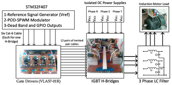
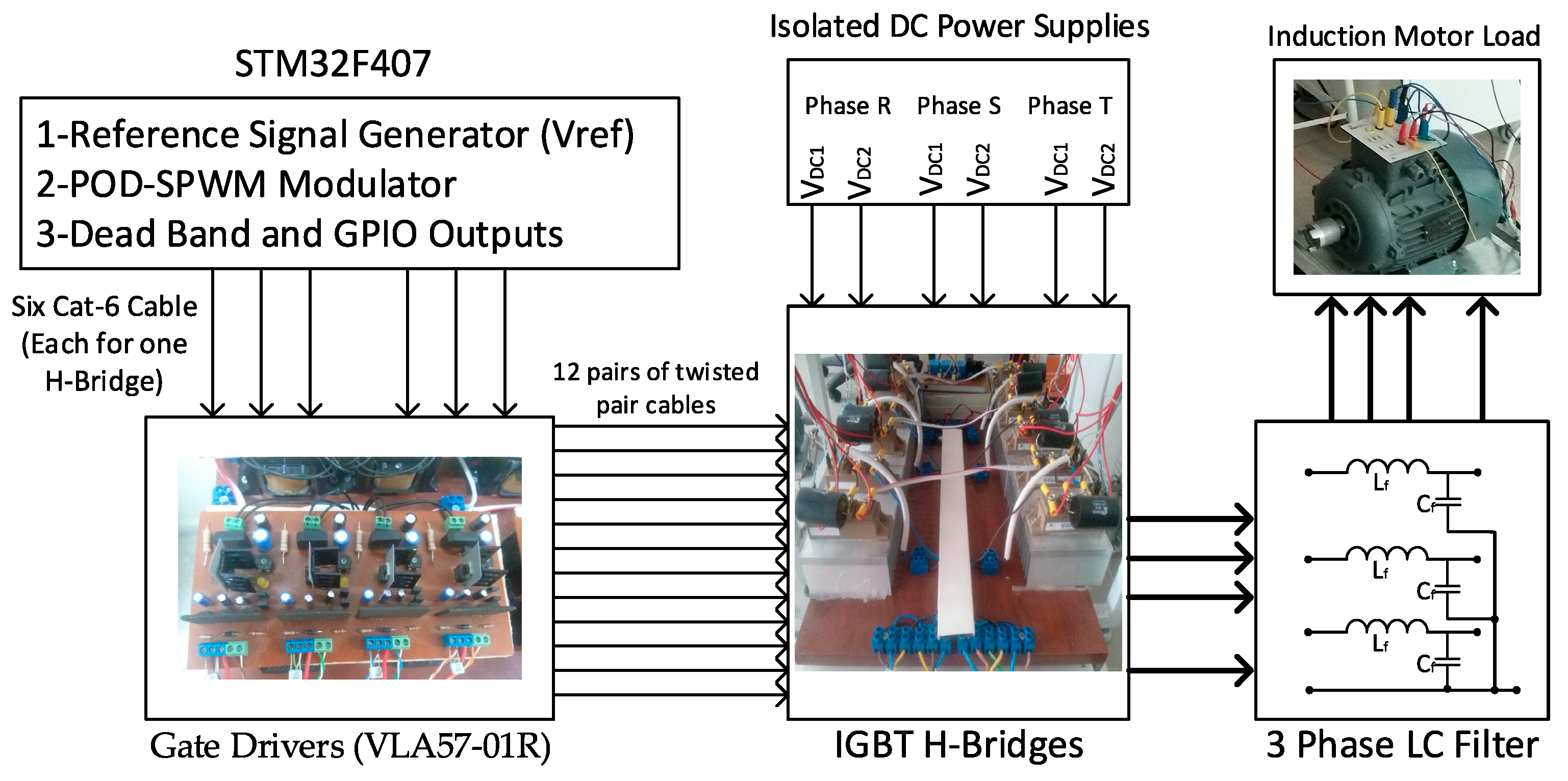
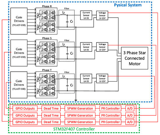
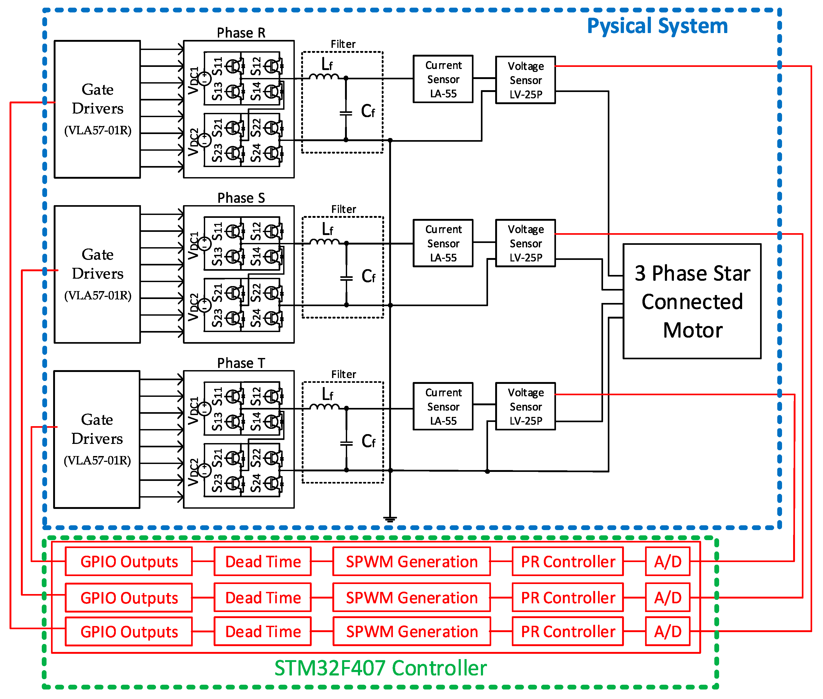
Following the validation of the ACMLI architecture through simulation studies, a laboratory-scale prototype was implemented to verify the practical feasibility of the system. In the initial phase, the power stage, consisting of the switching topology and gate driver circuits, was finalized to ensure reliable operation. A 32-bit ARM Cortex-M4-based STM32F407 microcontroller (STMicroelectronics, Plan-les-Ouates, Switzerland) was utilized to execute the control algorithms and generate the required SPWM switching signals. The comprehensive block diagram of the implemented inverter system, illustrating the integration of the control and power stages, is provided in Figure 13.
Figure 13.
Comprehensive hardware architecture and signal flow of the 3-phase 7-level ACMLI system, detailing the STM32F407 control unit, isolated gate drivers, and the induction motor load configuration.
To evaluate the system under realistic load conditions, a 4 kW star-connected asynchronous motor was utilized as the inverter output load. The specific electrical and mechanical parameters of this induction motor are detailed in Table 6. Furthermore, the LC filter parameters determined during the simulation phase were strictly maintained in the physical implementation to ensure consistency between theoretical and experimental results. The filter consists of a 6 mH inductor and a 20 µF capacitor, designed to mitigate high-frequency switching noise and provide a pure sinusoidal output.
Table 6.
Technical specifications of the 4 kW three-phase induction motor used as the experimental load.
The experimental implementation of the seven-level ACMLI was realized using twelve 2MBI100U4A-120-50 IGBT modules from Fuji Electric (Fuji Electric, Tokyo, Japan), each integrating two IGBTs (totaling 24 switches). These modules, featuring a 1200 V rating and 150 A capacity, ensure high power density. The control strategy was executed via an STM32F4 Discovery board using a Model-Based Design (MBD) approach. For this purpose, the Waijung blockset was integrated into the MATLAB R2022b/Simulink environment to manage peripheral interfaces such as ADC and GPIO.
To enhance signal integrity, an auxiliary interface board was developed to transmit switching signals via shielded RJ45 connectors, providing robust noise immunity. The gate drive stage utilizes VLA57-01R isolated drivers (Powerex, Youngwood, PA, USA), which offer essential galvanic isolation between the control and power circuits. For feedback acquisition, LV-25P and LA-55 sensors were employed for voltage and current measurements, respectively.
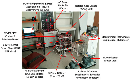
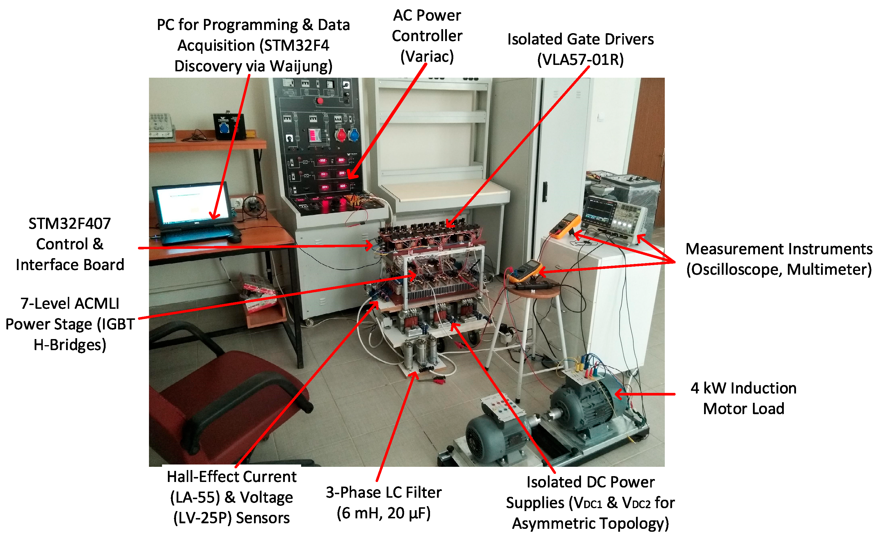
The physical hardware is organized in a three-tier rack configuration for optimal thermal management and electrical safety: the bottom tier contains the DC sources, the middle tier houses the ACMLI power stage and LC filters, and the top tier accommodates the control and driver boards. An overall view of the setup is provided in Figure 14. As illustrated in Figure 14, an AC Power Controller (Variac) was integrated to adjust these DC input levels to their nominal operating values. The initial tests were performed under open-loop POD-SPWM, incorporating a dead-band of 2.5 µs to prevent cross-conduction. For consistency with industrial standards, the inverter phases are designated as R, S, and T in the hardware implementation.
Figure 14.
Laboratory experimental setup of the 7-level ACMLI system, including the three-tier power rack, STM32F4 controller, and the 4 kW induction motor load.
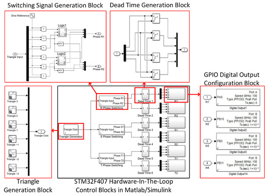
The experimental validation of the seven-level ACMLI was initially conducted in an open-loop configuration to establish a performance baseline. The switching signals were generated using a Model-Based Design (MBD) approach within the MATLAB/Simulink environment and executed by the STM32F407 microcontroller (STMicroelectronics, Plan-les-Ouates, Switzerland). The comprehensive block-based control architecture, including the internal logic for signal generation, is illustrated in Figure 15. As detailed in the hierarchical structure of Figure 15, the switching process begins with the generation of six distinct triangular carrier waves. These carriers are compared against sinusoidal reference signals to produce the Phase-Overlapping Discontinuous SPWM (POD-SPWM) patterns. To ensure the operational safety of the H-bridge topology, a specific dead-band logic was integrated into the control signal path, preventing potential short-circuit conditions during switching transitions. The finalized switching states were assigned to the digital output (GPIO) pins of the processor to drive the IGBT modules. For the experimental stage, the inverter phases are designated as R, S, and T, and the system’s open-loop response was evaluated using the 4 kW induction motor load prior to the implementation of the PR control strategy.
Figure 15.
Hierarchical MATLAB/Simulink control architecture for the STM32F407-based experimental system.
3.2. Open-Loop Experimental Results and Analysis
The performance of the ACMLI was initially evaluated in an open-loop configuration to establish a baseline for its switching characteristics and harmonic profile under realistic load conditions. The control algorithm was executed with a sampling period of 1 × 10⁻⁶ s, corresponding to a switching frequency of 8 kHz. To identify the optimal operating point, the system was analyzed across a range of ma (modulation index) values, where a value of 0.9 was selected based on yielding the minimum distortion.
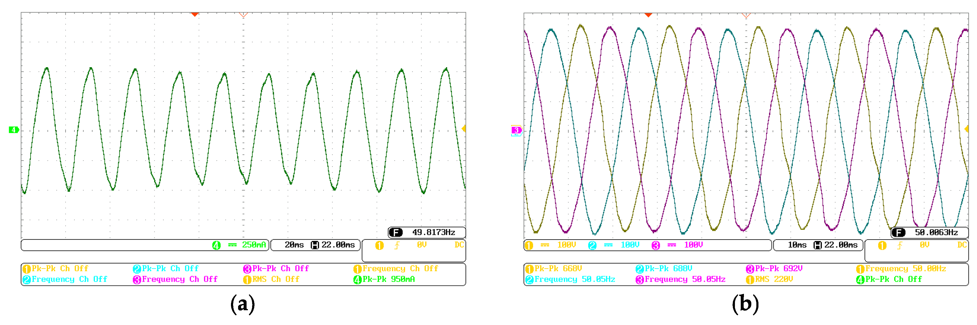
The experimental R-phase current waveform under the 4 kW induction motor load is presented in Figure 16a. The current exhibits a nearly sinusoidal profile with a peak-to-peak amplitude of approximately 950 mA. This smooth current waveform is a result of the high-frequency switching and the inherent inductive filtering capability of the motor.
Figure 16.
Experimental waveforms of the ACMLI under open-loop operation (without PR control): (a) R-phase load current (IR) and (b) three-phase output voltages (VRST).
Furthermore, the corresponding R-phase voltage waveform across the load is provided in Figure 16b. As observed, the voltage waveform follows a sinusoidal reference rather than a discrete stepped structure. This is due to the integration of a three-phase LC filter (6 mH and 20 µF) at the inverter output, which is utilized to suppress high-frequency switching harmonics and deliver a smoothed voltage profile to the motor terminals. The presence of the filter, combined with the dead-band effects and voltage drops across the switching elements, results in the final synthesized waveform shown. A more detailed spectral analysis will be conducted in the subsequent section to evaluate the baseline THDi and THDv levels.
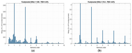
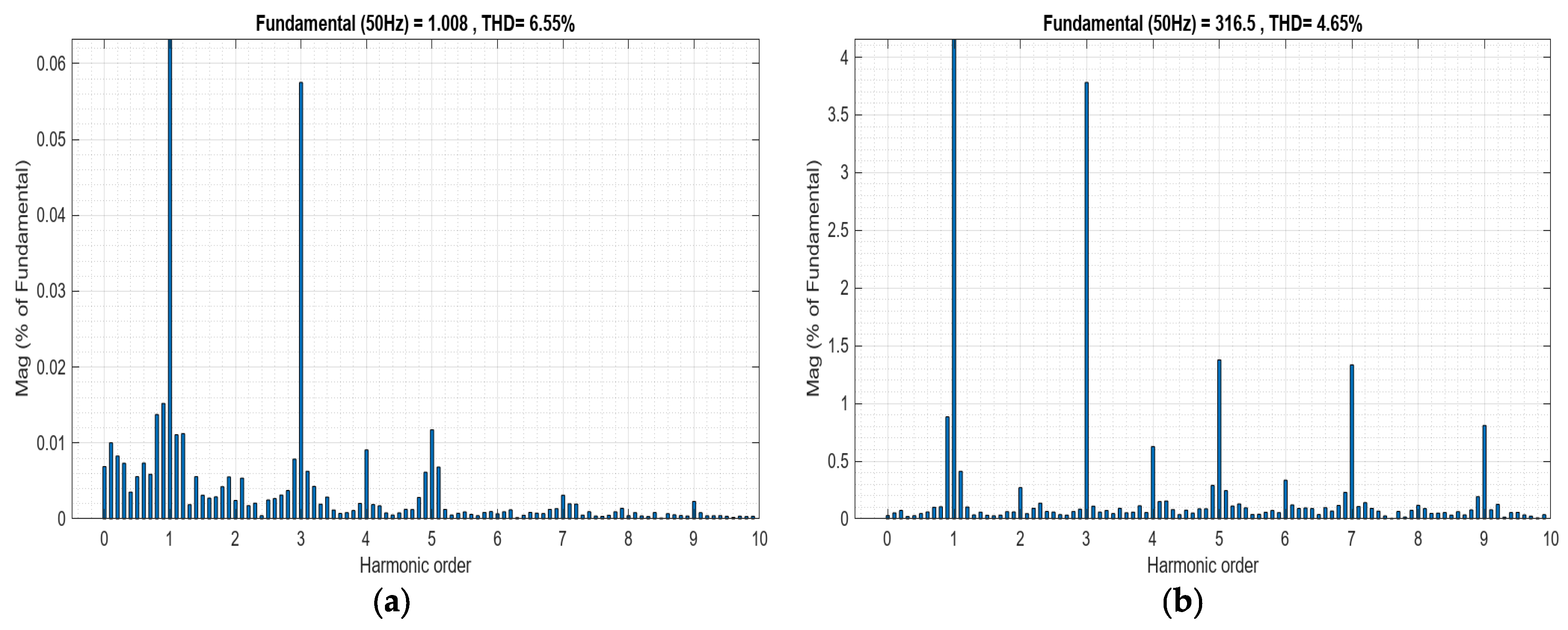
To comprehensively evaluate the baseline power quality of the ACMLI, a detailed spectral analysis was performed using FFT under open-loop operation. The harmonic profile and THD results for both current and voltage were obtained to serve as a reference for comparison with the closed-loop control scheme. Figure 17a illustrates the harmonic spectrum of the R-phase load current. The measured THDi was found to be 6.55%. A closer inspection of the specific harmonic orders, as detailed in Figure 17a, reveals that the third harmonic dominates the current spectrum with a magnitude of 5.70% relative to the fundamental component. This is followed by the fifth (1.16%), seventh (0.31%), and ninth (0.23%) harmonics. This baseline harmonic distribution highlights that although the multilevel structure effectively reduces high-frequency noise, lower-order harmonics remain significant under open-loop operation.
Figure 17.
Harmonic spectrum and spectral analysis of the ACMLI under open-loop operation: (a) R-phase load current (THDi) and (b) R-phase output voltage (THDv).
Furthermore, the spectrum of the synthesized output voltage is provided in Figure 17b. The voltage THD was recorded as 4.65%. Similar to the current profile, the third harmonic is the primary contributor, exhibiting a magnitude of 3.78%. The other low-order harmonics were measured as 1.38% (fifth), 1.33% (seventh), and 0.81% (ninth). These baseline results confirm that the integration of the three-phase LC filter effectively smooths the voltage steps and limits THDv to acceptable levels even before active compensation. The detailed distribution of these open-loop harmonic levels, dominated by third and fifth harmonics, underscores the necessity of implementing the PR control strategy to target and suppress these specific low-order harmonics.
A comparative evaluation of these recorded magnitudes against the IEEE 519-2022 standard confirms that the utilized PR controller effectively maintains the power quality within stringent international limits. The suppression levels achieved for the targeted low-order harmonics validate the resonance precision of the implemented control architecture under actual operating conditions. The marginal presence of the third and fifth harmonics, compared to the ideal simulation results, is an expected outcome of the hardware-induced non-idealities, such as dead-time effects and the non-linear voltage drops of the semiconductor switches. However, the overall spectral performance demonstrates that the utilized seven-level ACMLI system successfully shifts the harmonic energy to higher frequency bands, where it is effectively mitigated, ensuring a high-fidelity sinusoidal output.
3.3. Closed-Loop Experimental Results with PR Control
To actively address the low-order harmonics identified in the open-loop baseline analysis, particularly the significant third and fifth harmonics components, a PR control structure was integrated into the ACMLI system using the POD-SPWM technique. This closed-loop implementation aims to improve the output current and voltage quality by providing specific harmonic compensation at the fundamental and targeted resonant frequencies.
The complete closed-loop control architecture and signal flow are comprehensively illustrated in Figure 18. As shown in the system diagram, the voltage feedback is acquired from the filter output via a dedicated voltage sensing board. This acquired data is interfaced with the Analog-to-Digital Converter (ADC) inputs of the STM32F407 controller to be processed by the PR control block. Within the controller, the internal logic, as detailed in Figure 18, is executed based on the PR transfer function. The error signal (e) is first generated by comparing the incoming ADC data with an ideal 50 Hz sinusoidal reference (Vref), which is computationally synthesized within the STM32F407 processor. This error is then fed into the PR control block, designed with specific proportional (Kp) and resonant (Kr) gains tuned to minimize steady-state error at the fundamental frequency and suppress targeted harmonics. The PR controller’s output then serves as the dynamic reference signal for the final switching generation. The finalized switching signals are synthesized using the identical POD-SPWM logic from the open-loop stage (Figure 15) but are derived using this dynamic reference, as depicted in the ‘Switching signal generation’ portion of Figure 18.
Figure 18.
Comprehensive closed-loop control architecture for the STM32F407-based ACMLI system: integration of voltage feedback via ADC, implementation of the PR control block, and dynamic switching signal generation using POD-SPWM.
The selection of the PR control parameters (Kp and Kr) was conducted through a combination of theoretical analysis and simulation-based optimization. To ensure compatibility between the feedback loop and the internal reference signal of the controller, the voltage sampling amplitude was scaled to 3 V.
The proportional gain, Kp, primarily dictates the control signal amplitude and the resulting modulation index of the ACMLI. While simulation studies suggested a baseline value of 0.9, the parameter was tuned to 1.0 during the experimental phase to compensate for hardware-induced losses and signal attenuation in the voltage sensing stage. Stability tests were performed for Kp values ranging from 0.75 to 1.0; it was observed that values outside this range led to distortions in the sinusoidal output or insufficient modulation depth.
The resonant gain, Kr, plays a decisive role in targeting specific harmonic frequencies and determining the controller’s bandwidth. A parametric sweep was performed for Kr values (ranging from 0.0001 to 10) to evaluate their impact on THDi and THDv. It was found that excessively low Kr values resulted in inadequate gain at the resonant frequency, failing to suppress the targeted low-order harmonics. Conversely, high Kr values widened the bandwidth excessively, leading to the amplification of non-target frequencies and increasing the overall THD. Consequently, an optimal value of Kr = 0.01 was adopted, providing the best trade-off between harmonic rejection and system stability.
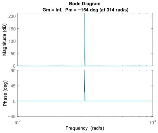
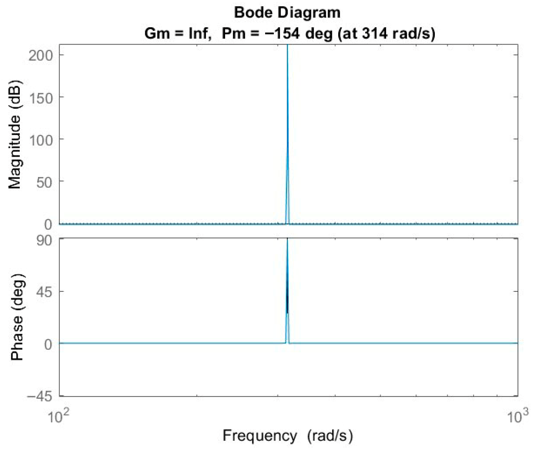
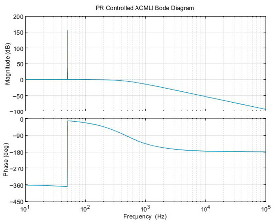
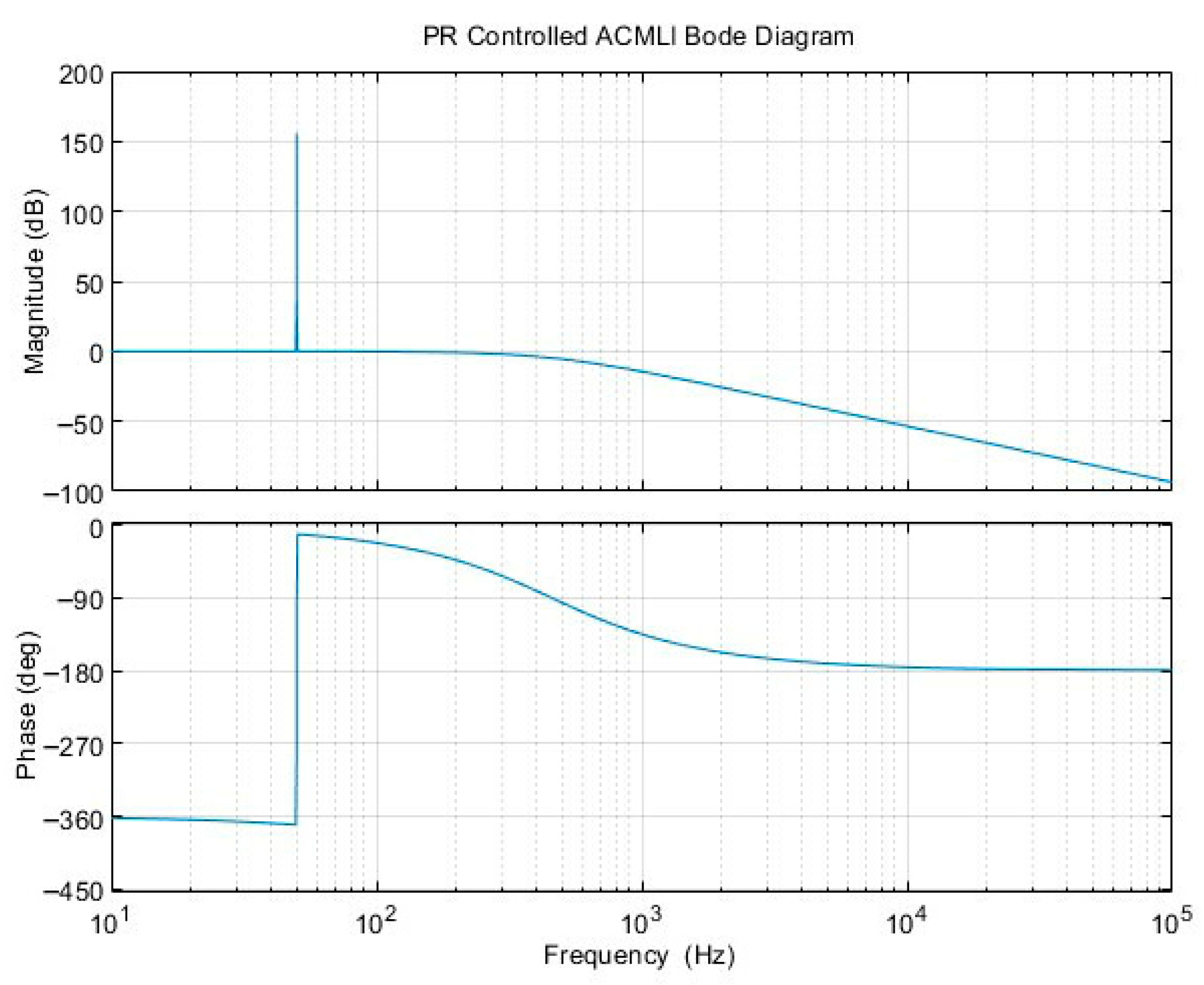
The stability and frequency response of the ACMLI system under the selected PR control parameters (Kp = 1.0, Kr = 0.01) are evaluated through the Bode diagram analysis shown in Figure 19. The open-loop frequency response, derived from the system’s transfer function, demonstrates the high-selectivity characteristic of the controller.
Figure 19.
Bode diagram of the ACMLI system illustrating the resonance effect and infinite gain at 50 Hz.
As observed in the magnitude plot, a sharp resonant peak is evident at the fundamental frequency of 50 Hz. This confirms the PR controller’s ability to provide high gain at the target frequency, which effectively minimizes the steady-state tracking error between the reference and measured signals. In the phase plot, the system maintains a positive phase margin for the specified Kp = 1.0 value, ensuring stable closed-loop operation. Furthermore, the analysis indicates that the selected Kp gain provides an optimal balance between dynamic response speed and stability margins. While increasing the proportional gain Kp would shift the gain-crossover frequency to a higher range, the current parameters ensure that the system operates within a safe stability region with sufficient damping, effectively preventing oscillations during transient states or load variations.
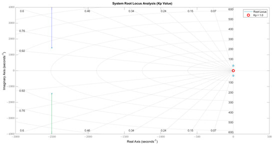
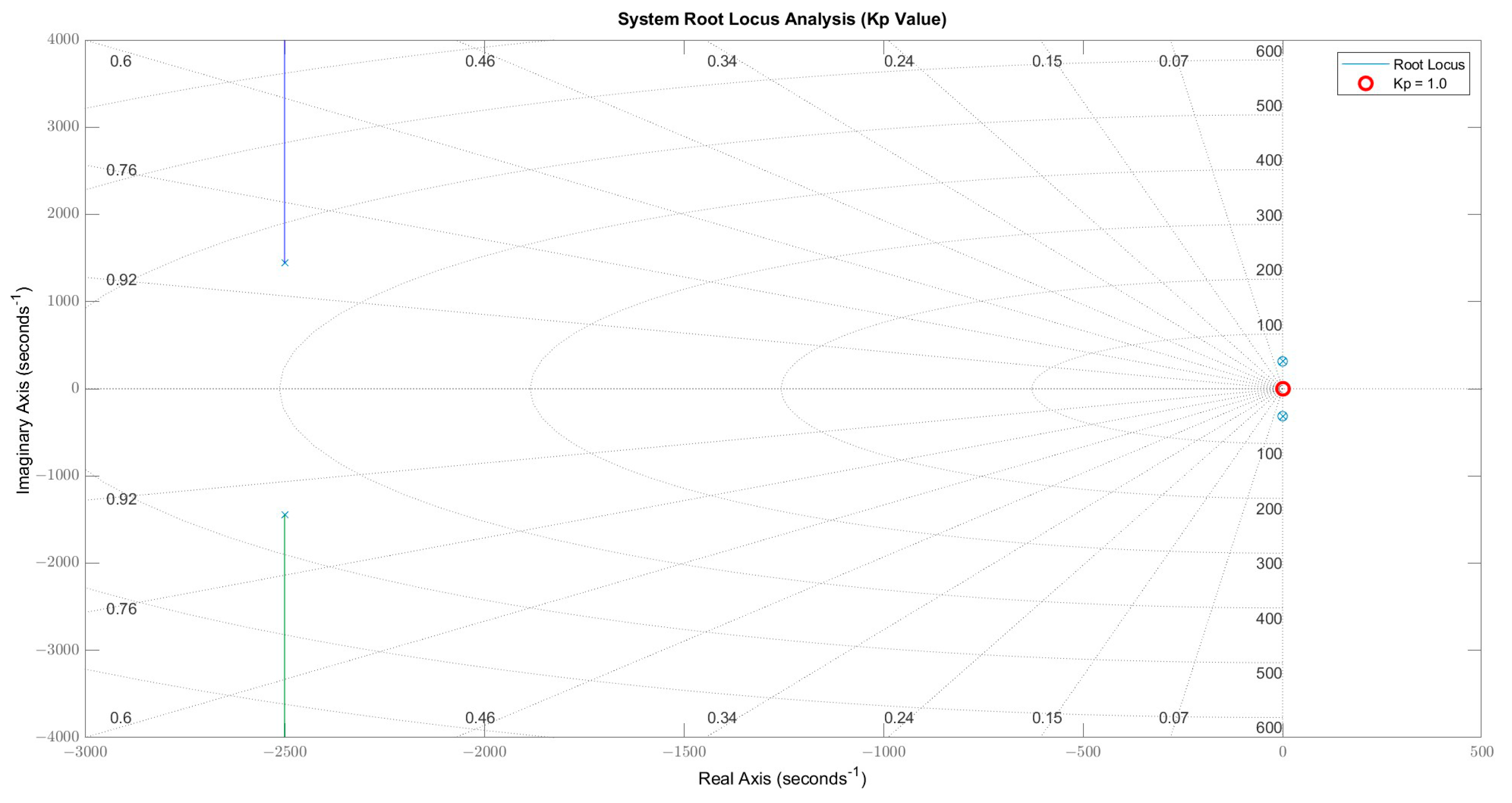
The trajectory of the system poles in the complex s-plane as a function of the proportional gain (Kp) is illustrated in the Root Locus analysis in Figure 20. This analysis provides a visual validation of the system’s stability regions and dynamic behavior under varying controller settings. For the selected value of Kp = 1.0, the dominant closed-loop poles are positioned in the left half-plane, ensuring asymptotic stability. At this operating point, the poles maintain a sufficient distance from the imaginary axis, providing a fast dynamic response while maintaining adequate damping to prevent undesired oscillations. The analysis reveals that if Kp is increased significantly beyond 1.0, the complex poles migrate closer to the imaginary axis; this reduces the damping ratio and leads to the undamped oscillations and sinusoidal distortions observed in the experimental phase.
Figure 20.
Root Locus analysis of the system, highlighting the trajectory of closed-loop poles for varying Kp values (Kp = 1.0 indicated).
Conversely, the effect of low Kp values was examined, showing that for Kp < 0.75, the poles move toward the real axis. This shift results in a more overdamped response, which slows down the system’s ability to track the 50 Hz reference signal and reduces overall harmonic suppression performance. Under the specific LC filter and load parameters of the experimental setup, the resonant poles of the PR controller effectively compensate for the voltage perturbations inherent in the asymmetric topology. Consequently, the parameters Kp = 1.0 and Kr = 0.01, optimized through both simulation and experimental tuning, were identified as the ideal operating point for achieving maximum harmonic rejection without compromising the system’s stability margins.
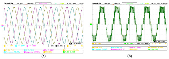
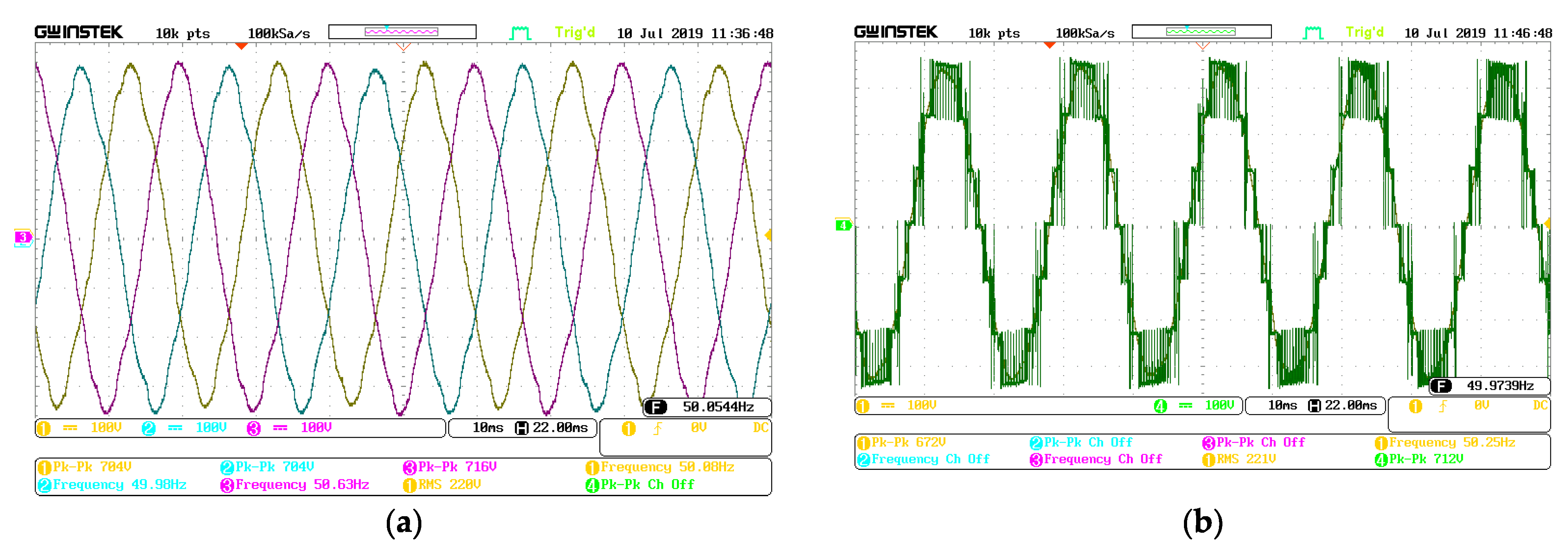
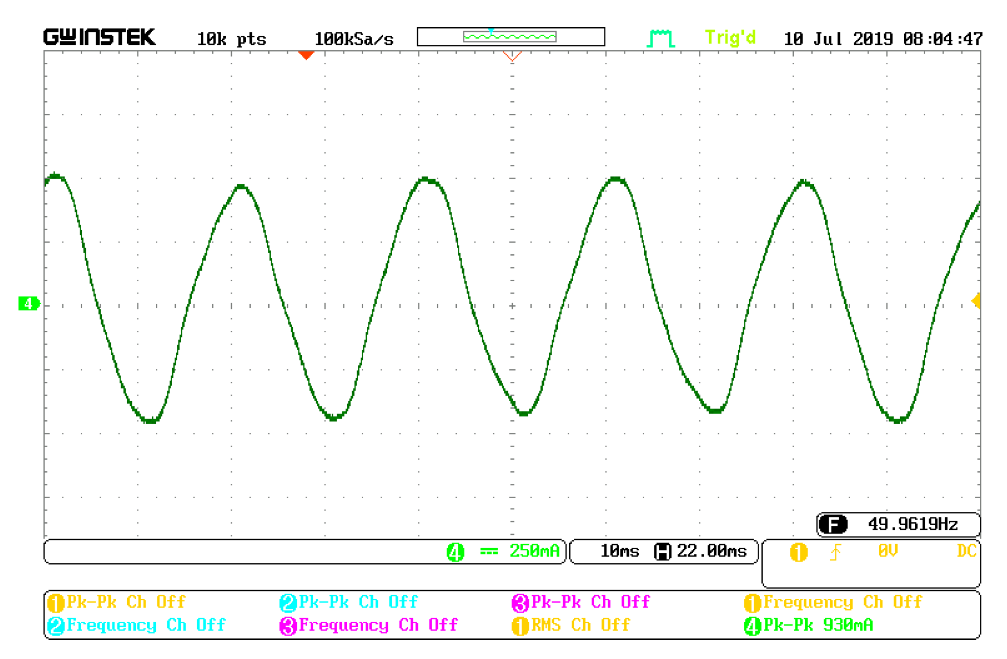
The experimental performance of the PR-controlled ACMLI was evaluated using the previously defined induction motor load and filter parameters, with the controller gains set to Kp = 1 and Kr = 0.01. Under these closed-loop conditions, the peak-to-peak (Vp−p) values of the RST phase voltages were measured as 660 V, 680 V, and 684 V, respectively. The balanced three-phase output voltage waveforms are illustrated in Figure 21a, while the unfiltered output voltage of the R-phase, showcasing the raw multilevel switching states, is presented in Figure 21b. The corresponding R-phase load current for the PR-controlled application is shown in Figure 22. The integration of the PR controller significantly improved the current periodicity compared to the open-loop stage. To quantify this improvement, spectral analyses were performed.
Figure 21.
Experimental results of the PR-controlled ACMLI (Kp = 1, Kr = 0.01): (a) RST phase output voltage waveforms and (b) non-filtered R-phase output voltage showing the raw switching levels.
Figure 22.
Measured R-phase load current waveform for the PR-controlled experimental system.
The step-wise output voltage of a single phase is detailed in Figure 21b. Each of the seven levels is generated by the precise coordination of the asymmetric DC links through the implemented POD-SPWM strategy. The uniform duration and amplitude across all levels, particularly at the transition points, validate the timing accuracy of the utilized digital control algorithm. This consistency ensures that the volt-second balance is maintained, which is essential for minimizing the low-order harmonic content in the utilized ACMLI configuration.
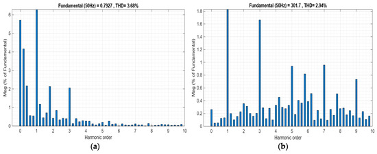
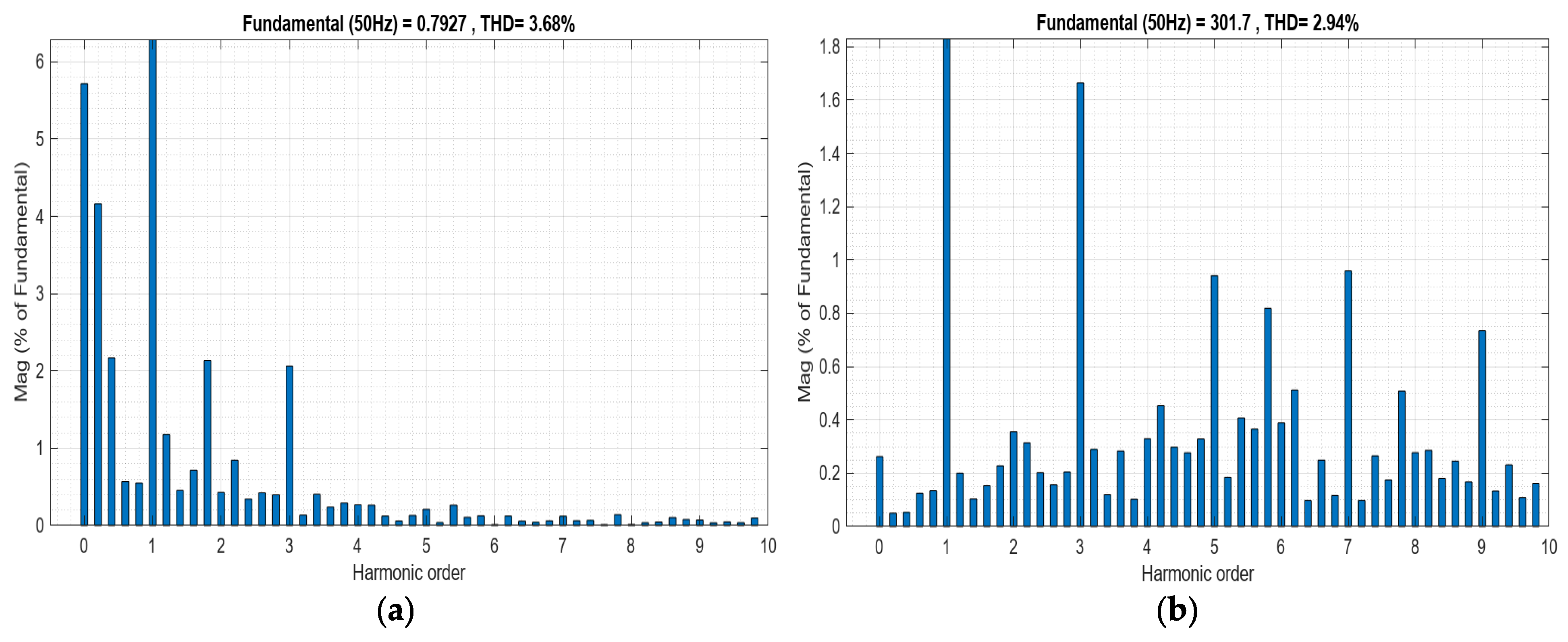
The spectral analysis of the PR-controlled ACMLI was conducted to evaluate the effectiveness of the resonant compensation at targeted frequencies. The resulting harmonic profiles for the R-phase output voltage and load current are illustrated in Figure 23a and Figure 23b, respectively. As summarized in the FFT analysis, the integration of the PR controller led to a significant reduction in low-order harmonics compared to the open-loop baseline. Specifically, the R-phase current harmonic profile showed a substantial improvement, with the Total Harmonic Distortion (THDi) dropping from 6.55% to 3.68%. A detailed examination of the harmonic orders reveals that the third harmonic (H3), which was the most dominant distortion source, was suppressed from 5.70% to 2.06%. Similarly, the fifth (0.21%), seventh (0.12%), and ninth (0.07%) harmonics were reduced to negligible levels.
Figure 23.
Spectral analysis and harmonic profile of the PR-controlled system: (a) R-phase load current THDi (3.68%) and (b) R-phase voltage THDv (2.94%).
Furthermore, the spectral distribution of the R-phase output voltage (THDv) was recorded as 2.94%, representing a significant decrease from the open-loop value of 4.65%. The individual harmonic components for the voltage were measured as 1.67% (H3), 0.94% (H5), 0.96% (H7), and 0.73% (H9). These results confirm that the PR controller provides exceptional gain at the resonant frequency, effectively neutralizing the periodic distortions inherent in the asymmetric switching process. The comparative results of the open-loop and closed-loop configurations are summarized in Table 7 to highlight the performance gains achieved through the PR control strategy.
Table 7.
Comparison of harmonic distortion levels between open-loop and PR-controlled operation.
The selection of the LC filter parameters is a trade-off between the harmonic attenuation performance and the physical size, cost, and dynamic response of the system. While a larger filter inductance or capacitance could further suppress high-frequency components, it would also increase the system’s weight, volume, and power losses. In this study, the LC filter is intentionally optimized to a minimal size by leveraging the high-frequency tracking and resonance-suppression capability of the PR controller. The PR controller provides high gain at the fundamental and selected harmonic frequencies, effectively reducing the filtering burden on the hardware. Regarding the filter stability, since the selected resonance frequency of the LC filter is well within the safe region and the PR controller’s bandwidth is carefully tuned, the system maintains stability without the need for additional active damping control. This single-loop strategy ensures both standard compliance and reduced hardware complexity.
4. Comparative Analysis and Validation of Results
The comparative analysis between the simulation models and experimental outcomes demonstrates that the integration of the PR controller significantly enhances power quality in both environments. As summarized in Table 8, the closed-loop system effectively suppresses harmonic components, ensuring that the ACMLI operates within the stringent limits defined by the IEEE 519 power quality standards.
Table 8.
Comprehensive comparison of THD results for simulation and experimental studies under open-loop and PR-controlled operation.
A high degree of correlation is observed between the theoretical models and the laboratory measurements. However, as expected in power electronic implementations, minor deviations exist due to the inherent complexities of hardware components. The experimental THDi and THDv values are consistently slightly higher than those obtained in simulations. This discrepancy is technically attributed to non-ideal factors such as:
- Switching and conduction losses in the power semiconductors;
- Measurement noise and quantization errors in the ADC sampling process;
- Parasitic resistance within the three-phase LC filter components.
Regarding the controller parameters, the optimal resonant gain (Kr = 0.01) identified during the simulation phase proved to be highly effective in the experimental setup for targeting low-order harmonics. To compensate for the voltage drops and signal attenuation within the physical feedback circuitry and sensing boards, the proportional gain (Kp) was precisely tuned from 0.9 in simulation to 1.0 in the hardware implementation. This adjustment was validated through the Bode and Root Locus analyses in Section 3, confirming that the system maintains robust stability margins at this operating point.
The voltage-feedback PR control strategy exhibits superior steady-state accuracy compared to open-loop operation. By providing high selective gain at the fundamental frequency, the controller successfully mitigates the third and fifth harmonics, which were the primary distortion sources in the open-loop configuration. The alignment between the simulation-based predictions and the experimental validation confirms that the implemented PR control approach is a robust and reliable solution for enhancing the performance of asymmetric cascaded multilevel inverters in islanded renewable energy applications.
The experimental results confirm that the utilized single-loop voltage-feedback PR control provides robust tracking performance and effectively mitigates harmonics without the need for an inner current loop. While dual-loop control structures are commonly used for current limiting and faster transient response, they increase the computational burden on the controller and require additional current sensors, which elevates the total system cost. For the islanded seven-level ACMLI application presented here, the implemented single-loop strategy offers a superior balance between simplicity and performance, maintaining full compliance with IEEE 519 standards while reducing hardware complexity.
4.1. Statistical Validation via Curve Fitting Analysis
To rigorously quantify the improvement in the sinusoidal quality of the output voltage provided by the PR controller, a statistical fitting analysis was performed using the MATLAB Curve Fitting Tool (CFT). This analysis evaluates how closely the experimental R-phase voltage waveforms (VR) under both open-loop and closed-loop operations align with an ideal sinusoidal model. The experimental data, captured as high-resolution time-series segments, were imported into the MATLAB workspace. A ‘Sum of Sine’ fitting model was applied to characterize the periodicity and deviation of the synthesized waveforms. The following statistical metrics were utilized to evaluate the fitting performance:
- SSE (Sum of Squares Due to Error): Indicates the total deviation of the experimental data points from the ideal sine fit; a value approaching zero represents minimal deviation.
- R-Square and Adjusted R-Square: Quantify the goodness-of-fit. Values approaching 1.0 indicate a near-perfect correlation with an ideal sine wave.
- RMSE (Root Mean Squared Error): Represents the standard deviation of the residuals, providing a measure of the fitting precision.
The comparative CFT results for the standard POD-SPWM (open-loop) and the PR-controlled POD-SPWM (closed-loop) are summarized in Table 9. The statistical evidence demonstrates a clear enhancement in the waveform quality upon activating the PR controller. Specifically, the SSE value decreased significantly from 1.178 × 10⁶ to 4.968 × 10⁵, reflecting a substantial reduction in total error. Furthermore, the R-Square value improved from 0.9976 to 0.9989. While this 0.0013 increase may appear marginal, in the context of high-precision power electronics, it indicates a significant reduction in harmonic residuals and a stronger alignment with the fundamental frequency. The reduction in RMSE from 10.86 to 7.049 further confirms the superior tracking performance and smoothed output characteristic achieved through the PR-based control strategy.
Table 9.
Statistical curve fitting results comparing open-loop and PR-controlled experimental waveforms.
4.2. Dynamic Response and Robustness Analysis Under Step-Load Disturbances
To rigorously evaluate the transient stability, disturbance rejection capability, and control bandwidth of the single-loop voltage-feedback PR strategy, a series of dynamic simulation tests was conducted. A critical concern in power electronic control is the system’s ability to maintain a stable output voltage under sudden load variations, which directly tests the controller’s effectiveness in compensating for internal impedance drops without a secondary current loop. In this context, a severe step-load disturbance was introduced at t = 0.1 s by connecting a parallel inductive-resistive load (5 Ω and 25 mH), effectively increasing the output current demand by approximately 150%. This operating point change provides a comprehensive benchmark to compare the open-loop system’s vulnerability against the PR-controlled system’s robust regulation performance. The following analyses of the voltage and current waveforms during this transient event demonstrate the high-speed recovery and spectral purity maintained by the proposed control architecture.
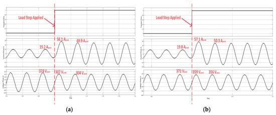
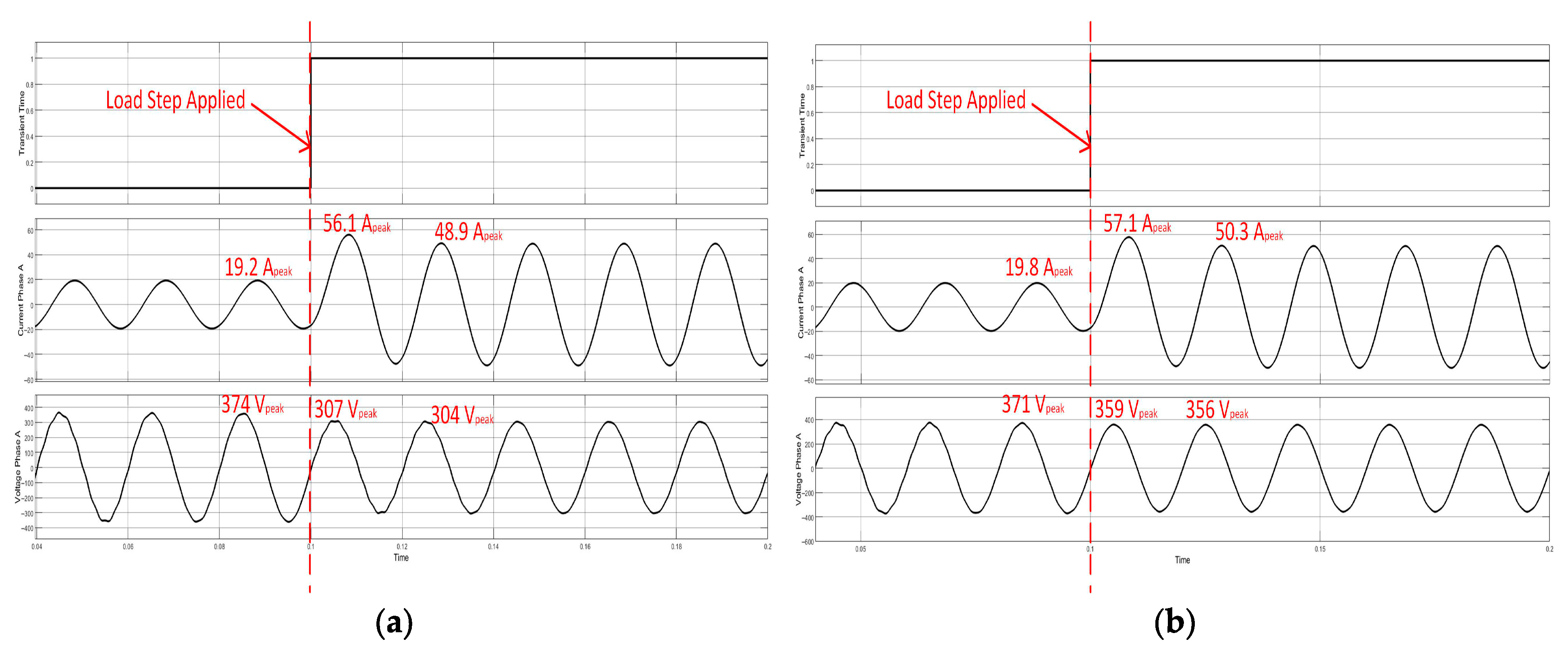
The comparative performance results under dynamic load conditions are presented in Figure 24. As illustrated in the time-domain waveforms, the open-loop system (Figure 24a) exhibits a significant and permanent voltage magnitude drop immediately following the load step at t = 0.1 s, failing to compensate for the increased voltage drop across internal impedances. In sharp contrast, the PR-controlled system (Figure 24b) demonstrates exceptional robustness; despite a 150% increase in current demand, the output voltage magnitude is fully restored to its reference value (356 Vpeak) within less than half a fundamental cycle (<10 ms). This rapid recovery effectively addresses the reviewer’s concerns regarding control bandwidth and proves that the high resonant gain of the PR controller at 50 Hz provides sufficient disturbance rejection without the necessity of a secondary current loop.
Figure 24.
Dynamic performance evaluation under a 150% step-load increase at t = 0.1 s: (a) Open-loop system showing permanent voltage sag; (b) PR-controlled system maintaining reference voltage magnitude.
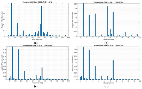
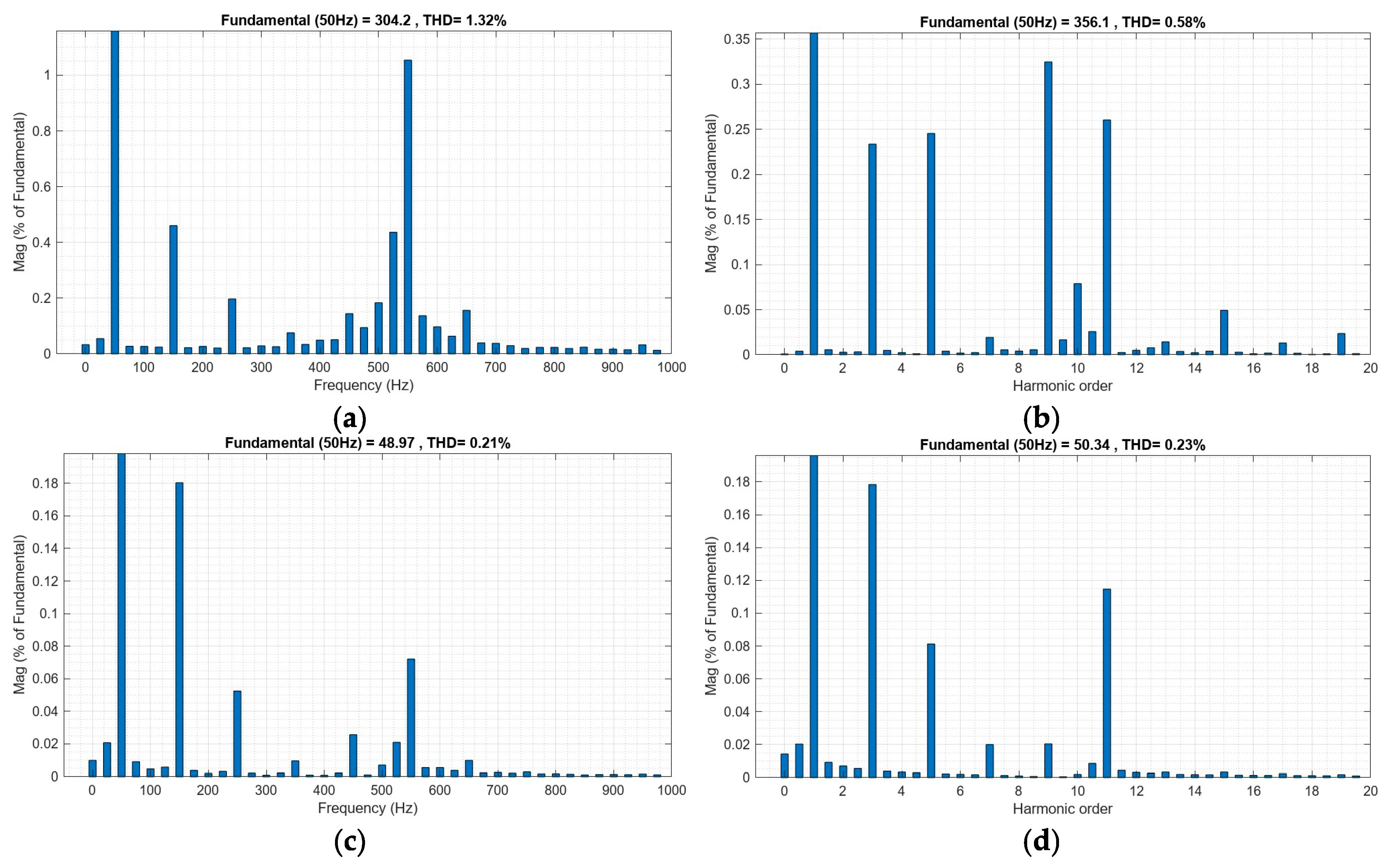
To comprehensively validate the controller’s effectiveness under severe operating point changes, the spectral purity of the output was analyzed following the step-load disturbance applied at t = 0.1 s. A post-transient window (specifically from 0.14 s to 0.18 s) was selected to ensure steady-state conditions, as mandatory for accurate FFT analysis. The comparative results, summarized in Figure 25 and detailed in Table 10, highlight substantial performance improvements. In the open-loop state (Figure 25a,c), the THDv increases to 1.32% due to uncontrolled internal impedance voltage drops under heavy load. Remarkably, under PR control (Figure 25b,d), the system not only prevents the voltage from sagging but also significantly enhances the spectral quality. The THDv is reduced by 56%, dropping from 1.32% to an impressive 0.58%. Furthermore, the THDi remains excellent at 0.23%, ensuring strict and continued compliance with IEEE 519 standards even under high-load stress. This dual achievement—simultaneous magnitude regulation and superior harmonic suppression without an auxiliary current loop—effectively addresses the concerns regarding control bandwidth and demonstrates the high robustness of the implemented single-loop voltage-feedback strategy.
Figure 25.
Comparative FFT harmonic analysis of output voltage and current under step-load conditions at t > 0.14 s: (a) Open-loop voltage THD; (b) PR-controlled voltage THD; (c) open-loop current THD; (d) PR-controlled current THD.
Table 10.
Comparative performance analysis following step-load disturbance in simulation.
According to the comparative results in Table 10, the open-loop system suffers from a substantial voltage sag, where the peak voltage drops from 374 V to 304 V (an 18.7% error). By implementing the PR control strategy, this deviation is successfully minimized, maintaining a robust peak voltage of 356 V (reducing the error to 4.04%) despite the heavy load. Furthermore, the THDv improvement from 1.32% to 0.58% confirms that the system not only regulates the magnitude but also maintains superior spectral purity, ensuring that the inverter output strictly conforms to IEEE 519 harmonic standards under dynamic disturbances.
The harmonic spectra presented in Figure 23 and Figure 25 clearly demonstrate the distribution of both low-order and high-order harmonics under PR-controlled operation. As observed, the dominant low-order harmonics (third, fifth, seventh, and ninth) are significantly suppressed compared to the open-loop case. In particular, the third harmonic component, which is typically dominant in asymmetric multilevel inverter structures, is reduced from 5.70% to 2.06% in the current spectrum and from 3.78% to 1.67% in the voltage spectrum. High-order harmonics, mainly originating from the switching process and PWM carrier frequency, are inherently attenuated by the LC output filter. Therefore, their contribution to the THD remains negligible. This confirms that the proposed voltage-feedback PR control effectively targets low-order harmonics, while the passive filter mitigates high-frequency components.
Theoretically, the harmonic components are expected to occur at integer multiples of the fundamental frequency (50 Hz). The experimental FFT results in Figure 23 and Figure 25 confirm that the measured harmonic frequencies (e.g., 150 Hz, 250 Hz, and 350 Hz) closely match the theoretical predictions (n.f0). Minor deviations observed in the frequency spectrum can be attributed to practical non-idealities such as switching delays, dead-time effects, measurement noise, and limited resolution of the FFT analysis. Despite these small discrepancies, the alignment between theoretical and experimental harmonic frequencies validates the accuracy of the system modeling and control design. In addition to integer-order harmonics, small inter-harmonic components can be observed in the experimental spectrum. These components typically arise from non-linear switching behavior, DC-link voltage imbalance, and modulation interactions in asymmetric cascaded structures.
Subharmonic components, although not dominant, may also appear due to modulation index variations and sampling-related effects in digital control implementation. However, their amplitudes remain significantly lower compared to the dominant low-order harmonics.
5. Conclusions
This study has successfully presented the design, implementation, and experimental validation of a voltage-feedback PR control strategy for a seven-level ACMLI. The research demonstrates that the implemented control architecture provides a robust and high-performance solution for medium-power applications, ensuring superior power quality and stable operation. By effectively managing the switching states of the asymmetric configuration, the system achieves a multi-level output that significantly reduces the voltage stress on power semiconductor components.
The primary advantage of the PR controller in this application is its ability to provide a high resonant gain at the fundamental frequency (50 Hz). This characteristic allows the controller to minimize steady-state tracking errors in the stationary reference frame without requiring the complex coordinate transformations associated with traditional PI-based schemes. The integration of voltage feedback is pivotal; by directly regulating the output voltage, the system gains enhanced control over the waveform purity, ensuring effective suppression of low-order harmonics and providing a fast dynamic response to load variations.
Specifically, the simulation results under a 150% step-load disturbance confirm that the PR controller can restore the output voltage to its reference magnitude in less than 10 ms. This rapid disturbance rejection capability, reducing the peak voltage error from 18.7% in open-loop to only 4.04% in closed-loop, validates the high control bandwidth of the single-loop architecture.
The performance of the PR-controlled ACMLI demonstrates a significant advantage over existing methods in the literature. The experimental voltage THD of 2.94% achieved in this study outperforms the results of Ponniran et al. (4.4%) using standard SPWM and Lemssaddak et al. (6.52%) using ANN + PI-based structures. Furthermore, the PR controller reduced the experimental current THD from 6.55% to 3.68%, confirming full compliance with the IEEE 519 power quality standards. Moreover, the robustness of the strategy was further evidenced under dynamic conditions, where the THDv was significantly enhanced by 56%, dropping from 1.32% to 0.58% during post-transient operation. This level of harmonic suppression under heavy load stress demonstrates a substantial improvement over uncontrolled systems and aligns with the most stringent power quality requirements. While some studies in the literature, such as Dehkordi et al., reported lower THD values (1.54%) for simple two-level inverters, the proposed study achieves a highly competitive result within a complex seven-level asymmetric architecture, even when accounting for real-world factors such as switching losses, sensor noise, and parasitic resistances. The ability of the proposed single-loop scheme to outperform complex dual-loop or AI-based structures in terms of both dynamic recovery and spectral purity highlights its practical efficiency and reduced computational burden.
The statistical validation performed via Curve Fitting Analysis (R2 = 0.9989) further confirms the high correlation between the theoretical models and the experimental outcomes. Future research will focus on enhancing the adaptability of the PR control scheme by integrating adaptive tuning algorithms to handle grid frequency fluctuations automatically. Additionally, extending this strategy to three-phase systems under unbalanced grid conditions remains a key area of interest. These advancements will further solidify the role of PR-controlled ACMLIs in the next generation of resilient renewable energy systems.
Author Contributions
Conceptualization, İ.Ç. and E.K.; methodology, E.K.; software, G.K.; validation, G.K., İ.Ç. and E.K.; formal analysis, G.K.; resources, E.K. and G.K.; writing—original draft preparation, G.K.; writing—review and editing, G.K.; supervision, İ.Ç. and E.K.; project administration, İ.Ç. and E.K. All authors have read and agreed to the published version of the manuscript.
Funding
This research received no external funding.
Data Availability Statement
The raw data supporting the conclusions of this article will be made available by the authors on request.
Conflicts of Interest
The authors declare no conflicts of interest.
Abbreviations
The following abbreviations are used in this manuscript:
| MLI | Multilevel Inverter |
| ACMLI | Asymmetric Cascaded Multilevel Inverter |
| THD | Total Harmonic Distortion |
| THDi | Total Harmonic Distortion of Current |
| THDv | Total Harmonic Distortion of Voltage |
| PR | Proportional-Resonant |
| CHB | Cascaded H-Bridge |
| PWM | Pulse Width Modulation |
| SPWM | Sinusoidal Pulse Width Modulation |
| POD-SPWM | Phase Opposition Disposition Sinusoidal PWM |
| ADC | Analog-to-Digital Converter |
| HIL | Hardware-in-the-Loop |
| CFT | Curve Fitting Tool |
| SSE | Sum of Squares Due to Error |
| RMSE | Root Mean Squared Error |
| R2 | R-Square (Coefficient of Determination) |
| Kp | Proportional Gain |
| Kr | Resonant Gain |
| IEEE | Institute of Electrical and Electronics Engineers |
References
- Benevieri, A.; Cosso, S.; Formentini, A.; Marchesoni, M.; Passalacqua, M.; Vaccaro, L. Advances and Perspectives in Multilevel Converters: A Comprehensive Review. Electronics 2024, 13, 4736. [Google Scholar] [CrossRef] [Scilit]
- Rohten, J.; Villarroel, F.; Silva, J.; Pulido, E.; Pierart, F.; Guzmán, J.; García-Santander, L. Power Converter Resonant Control for an Unbalanced and Non-Constant Frequency Supply. Sensors 2023, 23, 4884. [Google Scholar] [CrossRef] [Scilit]
- Isazadeh, A.; Adabi, J.; Rezanejad, M.; Adabi, M.E. Operation and control of a grid-connected asymmetric cascade multi-level inverter. IEEE J. Emerg. Sel. Top. Power Electron. 2020, 9, 1614–1623. [Google Scholar]
- Tackie, S.N.; Nur, Z.M.; Ozerdem, O.C.; Falana, W.O. An Asymmetric Minimal Component Count Three-Phase Multilevel Converter Suitable for PV Applications. In Proceedings of the 2nd International Conference on Advances in Electrical, Electronics, Energy, and Computer Sciences ICEEECS; SciTePress: Setúbal, Portugal, 2026; pp. 153–163. [Google Scholar] [CrossRef] [Scilit]
- Frequente, G.; Caruso, M.; Schettino, G.; Miceli, R. Assessment of a Hybrid Modulation Strategy for Asymmetrical Cascaded Multilevel Inverters Under Comparative Analysis. Electronics 2025, 14, 4354. [Google Scholar] [CrossRef] [Scilit]
- Wijaya, V.P.; Info, A.; Inverter, M. Analysis and Experimental Study of a Seven Level Inverter. J. Ind. Autom. Electr. Eng. 2025, 2, 144–151. [Google Scholar]
- Keven, G. Asimetrik Çok Seviyeli Kaskad Evirici Tasarımı ve Uygulaması. Ph.D. Thesis, Gazi University, Ankara, Türkiye, 2019. [Google Scholar]
- Ahmad, S.; Khan, I.; Iqbal, A.; Rahman, S. A Novel Pulse Width Amplitude Modulation for Elimination of Multiple Harmonics in Asymmetrical Multilevel Inverter. In Proceedings of the 2021 IEEE Texas Power and Energy Conference TPEC 2021, College Station, TX, USA, 2–5 February 2021. [Google Scholar] [CrossRef] [Scilit]
- Buccella, C.; Cimoroni, M.G.; Cecati, C. Mitigation Technique for Cascaded H-Bridge Multilevel Inverters Based on Pulse Active Width Modulation. IEEE J. Emerg. Sel. Top. Power Electron. 2023, 11, 999–1008. [Google Scholar] [CrossRef] [Scilit]
- Choudhury, S.; Bajaj, M.; Dash, T.; Kamel, S.; Jurado, F. Multilevel Inverter: A Survey on Classical and Advanced Topologies, Control Schemes, Applications to Power System and Future Prospects. Energies 2021, 14, 5773. [Google Scholar] [CrossRef] [Scilit]
- Samsudin, M.S.; Alias, A.; Said, N.A.M.; Patkar, F.; Lazi, J.M.; Talib, M.H.N.B.; Aihsan, M.Z. Comparative Study of Sinusoidal PWM Strategies in Cascaded Multilevel Inverters. J. Power Energy Eng. 2025, 13, 95–116. [Google Scholar] [CrossRef]
- Çakmak, F.; Meral, M.E. Comparative Analysis of PI and PR Control Strategies for Enhancing Voltage Quality in D-Statcom-Based Distribution Networks. Balk. J. Electr. Comput. Eng. 2025, 12, 282–293. [Google Scholar] [CrossRef] [Scilit]
- Munawar, S.; Iqbal, M.S.; Adnan, M.; Akbar, M.A.; Bermak, A. Multilevel Inverters Design, Topologies, and Applications: Research Issues, Current, and Future Directions. IEEE Access 2024, 12, 149320–149350. [Google Scholar] [CrossRef] [Scilit]
- Rana, R.A.; Patel, S.A.; Muthusamy, A.; Lee, C.W.; Kim, H.J. Review of Multilevel Voltage Source Inverter Topologies and Analysis of Harmonics Distortions in FC-MLI. Electronics 2019, 8, 1329. [Google Scholar] [CrossRef] [Scilit]
- Sunddararaj, S.P.; Rangarajan, S.S.; Subashini, N. An Extensive Review of Multilevel Inverters Based on Their Multifaceted Structural Configuration, Triggering Methods and Applications. Electronics 2020, 9, 433. [Google Scholar] [CrossRef] [Scilit]
- Hamidi, M.N.; Marzuki, A.; Ishak, D.; Salem, M.; Marzaki, M.H.; Ukaegbu, I.A. Asymmetrical Multilevel Inverter-Based PV System with Voltage Feedback Control: An Experimental Validation. Appl. Sci. 2022, 12, 3581. [Google Scholar] [CrossRef] [Scilit]
- Ponniran, A.; Yatim, M.H.; Kasiran, M.A.N.; Noor, M.K.R.; Hasanah, R.N.; Djuriatno, W. 7-Level of Asymmetric MLI with Reduced Number of Switching Devices Structure for High Power-Density Achievement Using Pareto-Front Method. Int. J. Integr. Eng. 2025, 17, 1–11. [Google Scholar] [CrossRef] [Scilit]
- Dehkordi, N.M.; Daneshmehr, A.; Hamzeh, M. Robust Tuning of Proportional Resonant Controllers for Islanded Three-Phase Inverters With Parametric Uncertainty and Interval Time Delay. IEEE Trans. Ind. Electron. 2025, 72, 13382–13393. [Google Scholar] [CrossRef] [Scilit]
- Babaie, M. Design and Development of Advanced Model-Based Robust Multi-Objective Controllers for Multilevel Converters. Ph.D. Thesis, École de Technologie Supérieure Université du Québec, Montreal, QC, Canada, 2023. [Google Scholar]
- Biricik, S.; Komurcugil, H.; Ahmed, H.; Sharifzadeh, M.; Mehrasa, M.; Al-Haddad, K. Proportional-Resonant Based Control Strategy for Grid-Connected Packed-E Cell Inverters with Lyapunov Filter-Based PLL. IET Gener. Transm. Distrib. 2023, 17, 645–654. [Google Scholar] [CrossRef] [Scilit]
- Salimin, S.; Noor, A.F.B.M.; Jumaat, S.A. Proportional Resonant Current Controller Strategy in Inverter Application. Int. J. Power Electron. Drive Syst. 2019, 10, 2238–2244. [Google Scholar] [CrossRef] [Scilit]
- Lim, K.; Choi, J. Seamless Grid Synchronization of a Proportional+resonant Control-Based Voltage Controller Considering Non-Linear Loads under Islanded Mode. Energies 2017, 10, 1514. [Google Scholar] [CrossRef] [Scilit]
- Rojas, C.A.; Kouro, S.; Inzunza, R.; Mitsugi, Y.; Alcaide, A.M. Harmonic Impedance Model of Multiple Utility-Interactive Multilevel Photovoltaic Inverters. Energies 2022, 15, 9462. [Google Scholar] [CrossRef] [Scilit]
- Colak, I.; Kabalci, E.; Keven, G. The Effects of PR Control in Three-Level Single-Phase Multilevel Inverter. 8th Int. Conf. Renew. Energy Res. Appl. ICRERA 2019, 2019, 821–826. [Google Scholar] [CrossRef] [Scilit]
- Lamkharbach, Y.; Aniba, G.; Chebak, A. Design and Implementation of Quasi-Proportional-Resonant Controller of LCL Filter Inverter with Grid Current Feedback Active Damping in Weak Grid to Enhance Stability. Ain Shams Eng. J. 2025, 16, 103724. [Google Scholar] [CrossRef] [Scilit]
- Leong, Y.F.; Ramlan, N.H.; Ab-Ghani, S.; Daniyal, H. Particle Swarm Optimization Based Proportional-Integral Online-Tuning by Fuzzy Logic Controller (PSOFLC-PI) for Cascaded Multilevel Inverter Different Load Scenarios. In Proceedings of the 2025 IEEE 8th International Conference on Electrical, Control and Computer Engineering (InECCE), Kuantan, Malaysia, 27–28 August 2025; pp. 31–36. [Google Scholar] [CrossRef] [Scilit]
- Wang, X.; Wang, S.; Wang, S.; Yang, C.; Zhao, X. A Digital Delay Compensation Method to Improve the Stability of LCL Grid-connected Inverters. Energies 2021, 14, 2730. [Google Scholar] [CrossRef] [Scilit]
- Matthews, P.D.; Narm, H.G.; Ebrahimi, J.; Eren, S. A Control Strategy for Parallel Three-Phase Inverters in Motor Drives. IEEE Open J. Power Electron. 2025, 6, 1815–1827. [Google Scholar] [CrossRef] [Scilit]
- Han, J.; Lv, X.; Chen, H.; Yao, G.; Wang, T. Virtual Voltage Vector–Based Polynomial-Fitted Sampled-Data Model Predictive Control for Single-Phase Asymmetric Cascaded H-Bridge Inverter. Int. J. Circuit Theory Appl. 2025, 1–13. [Google Scholar] [CrossRef] [Scilit]
- Ali, K.; Yang, G.; Imtiaz, S.; Altimania, M.R.; Memon, A.L.I.; Munir, H.M. Fault-Tolerant Control of CHB Multilevel Inverter Using Adaptive Multi-Objective MPC. IEEE Access 2026, 14, 13636–13650. [Google Scholar] [CrossRef] [Scilit]
- Lemssaddak, S.; Hakam, Y.; Tabaa, M.; Elmahjoub, A.A.; Zegrari, M. Intelligent Control of a 7-Level Multilevel Inverter Using ANN and PI Controllers Implemented on DSP TMS320F28379D. In Proceedings of the 2025 37th International Conference on Microelectronics (ICM); IEEE: New York, NY, USA, 2026; pp. 1–5. [Google Scholar]
- Valluvan, B.; Chandrasekaran, K. New-Level Generation Module Using Reduced Current Conducting Devices for Cascaded Multilevel Inverter Topology. Automatika 2026, 67, 37–48. [Google Scholar] [CrossRef] [Scilit]
- Colak, I.; Kabalci, E.; Keven, G. Comparision of Multi-Carrier Techniques in Seven-Level Asymmetric Cascade Multilevel Inverter. In Proceedings of the 4th International Conference on Power Engineering, Energy and Electrical Drives, Istanbul, Turkey, 13–17 May 2013; pp. 1619–1624. [Google Scholar] [CrossRef] [Scilit]

Disclaimer/Publisher’s Note: The statements, opinions and data contained in all publications are solely those of the individual author(s) and contributor(s) and not of MDPI and/or the editor(s). MDPI and/or the editor(s) disclaim responsibility for any injury to people or property resulting from any ideas, methods, instructions or products referred to in the content. |
© 2026 by the authors. Licensee MDPI, Basel, Switzerland. This article is an open access article distributed under the terms and conditions of the Creative Commons Attribution (CC BY) license.