


Abstract
This paper presents the fabrication and experimental characterization of a 316L stainless-steel WR-90 waveguide horn antenna manufactured using selective laser melting (SLM) and operating across the X-band (8.2–12.4 GHz). The antenna is designed based on standard WR-90 waveguide theory and incorporates a coaxial-to-waveguide transition and a flared radiating aperture to achieve stable aperture-based radiation. Full-wave electromagnetic simulations are performed to establish baseline impedance, radiation pattern, and gain performance prior to fabrication. The SLM-fabricated prototype is evaluated through reflection coefficient, radiation pattern, and realized gain measurements conducted in an anechoic chamber. Measured results confirm stable impedance matching across the entire band, with |S11| below −10 dB and a minimum of −22.34 dB near 10.1 GHz. The radiation patterns closely follow simulation predictions, with half-power beamwidth deviations below 4%. The realized gain increases from 11.2 dBi to 15.8 dBi across the band, with simulation–measurement deviation decreasing to within 0.5 dB above 10 GHz. Rather than focusing on antenna design novelty, this work employs a standardized WR-90 horn antenna as a benchmark structure to isolate fabrication-induced effects. A quantitative performance analysis is introduced by converting the gain deviation into an equivalent efficiency reduction, providing a practical framework for evaluating fabrication-induced electromagnetic degradation in SLM-fabricated waveguide components.
1. Introduction
Rectangular waveguide antennas operating in the X-band continue to play an important role in radar [1,2], sensing, and microwave measurement systems [3,4,5,6] due to their low transmission loss, high power-handling capability, and stable single-mode propagation characteristics [7,8,9]. Among standard waveguide formats, the WR-90 waveguide supports the dominant TE10 mode over the frequency range of 8.2–12.4 GHz and remains widely adopted for both guided-wave components and horn antenna structures in industrial and research applications.
Conventional fabrication of WR-90 waveguide antennas typically relies on precision machining processes, which provide excellent dimensional accuracy and surface quality. However, these methods are often associated with higher manufacturing cost, longer lead times, and limited flexibility for rapid design iteration. In recent years, metal additive manufacturing—particularly selective laser melting (SLM)—has emerged as an attractive alternative for the fabrication of microwave waveguide components and antennas [10,11,12]. SLM enables direct fabrication of fully metallic three-dimensional structures from digital models, offering advantages in rapid prototyping, geometric flexibility, and integration of complex features within a single build.
Several prior works have reported SLM-fabricated waveguide and horn antennas operating in the X-band and millimeter-wave regimes [10,11,12,13,14,15,16,17]. These studies demonstrate that additive manufacturing can achieve acceptable impedance matching, radiation patterns, and gain performance comparable to conventionally manufactured structures. However, many investigations primarily focus on antenna-level metrics while assuming idealized bulk material properties in electromagnetic simulations. The influence of fabrication-induced characteristics—such as surface morphology, layer-by-layer fusion features, and microstructural inhomogeneity—on practical RF performance is often discussed qualitatively rather than analyzed quantitatively.
For waveguide-based antennas, electromagnetic fields are strongly confined to the metallic boundaries, and conductor-related losses directly affect radiation efficiency and realized gain. Even moderate deviations between simulated and measured gain may therefore provide insight into the electromagnetic impact of additive manufacturing processes. A systematic comparison between full-wave simulation results obtained using nominal bulk conductivity values and experimental measurements can enable quantitative interpretation of fabrication-induced performance degradation without requiring explicit multi-scale surface modeling.
However, despite these developments, a clear and practical methodology for quantitatively interpreting fabrication-induced electromagnetic performance degradation in additively manufactured waveguide antennas remains limited. In particular, while prior studies report simulation and measurement results, a systematic approach to relate the observed gain deviation to an equivalent efficiency reduction using a standardized reference structure has not been sufficiently addressed. Rather than focusing on antenna design novelty, this work employs a standard WR-90 horn antenna as a benchmark structure to isolate fabrication-induced effects and enable controlled evaluation of SLM-related performance degradation. Therefore, this work aims to fill this gap by introducing a quantitative performance interpretation framework based on a well-defined WR-90 horn antenna, enabling direct assessment of SLM-induced loss mechanisms in a controlled and physically interpretable manner.
In this work, a WR-90 waveguide horn antenna fabricated from 316L stainless steel using SLM technology is experimentally investigated across the X-band (8.2–12.4 GHz). The antenna consists of a coaxial-to-waveguide transition and a flared radiating aperture designed according to standard waveguide theory. Full-wave electromagnetic simulations are performed using CST Microwave Studio [18] to establish baseline impedance, radiation pattern, and gain performance. The fabricated prototype is subsequently characterized through reflection coefficient measurement using a vector network analyzer, far-field radiation pattern analysis with a standard gain horn reference and realized gain evaluation across the operating band.
In addition to conventional performance validation, a quantitative performance analysis is performed by converting the measured gain deviation relative to simulation into an equivalent efficiency reduction. This approach provides a practical interpretation of conductor-related losses associated with the SLM-fabricated 316L structure and allows assessment of fabrication-induced degradation within the X-band. Surface morphology and elemental composition are examined using scanning electron microscopy (SEM) and energy-dispersive X-ray spectroscopy (EDX), verifying structural integrity and material consistency of the printed alloy.
The results demonstrate that SLM-based fabrication can reliably reproduce the intended WR-90 horn antenna behavior for X-band applications while introducing measurable but manageable performance deviations. The study provides an experimentally supported and quantitatively interpreted evaluation of SLM-fabricated waveguide horn antennas, offering practical guidance for implementing metal additive manufacturing in microwave antenna development.
2. Waveguide Propagation Theory and Antenna Design
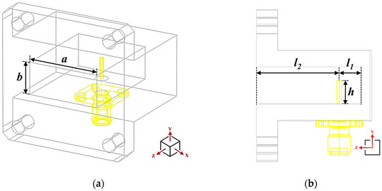
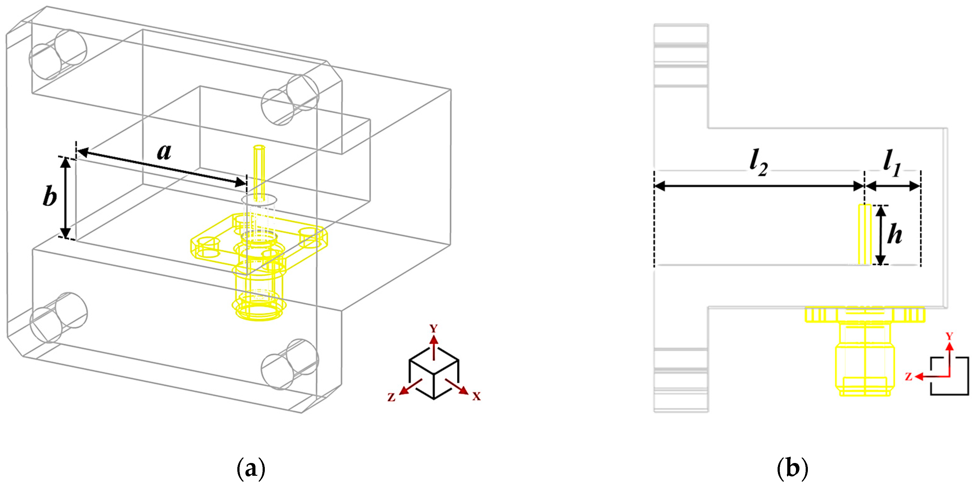
The proposed antenna is based on the standard WR-90 rectangular waveguide, which is widely employed in X-band microwave systems due to its stable single-mode operation, predictable electromagnetic behavior, and suitability for precision fabrication. The internal dimensions of the WR-90 waveguide are a = 22.86 mm and b = 10.16 mm, corresponding to the broad and narrow wall dimensions, respectively. The overall geometry of the waveguide structure and coaxial feeding configuration is illustrated in Figure 1. For a rectangular waveguide, the cutoff frequency of the dominant TE10 mode is given by [19]
where c is the speed of light in free space. Substituting a = 22.86 mm yields a cutoff frequency of approximately 6.56 GHz, ensuring single-mode operation across the X-band frequency range from 8.2 GHz to 12.4 GHz. For frequencies above cutoff, the phase propagation constant is expressed as [19]
where k0 is the free-space wavenumber and f is the operating frequency. These propagation characteristics govern the phase evolution of the guided wave and directly influence the radiation behavior of the antenna.
Figure 1.
Geometry of the WR-90 waveguide-to-coaxial transition used to excite the antenna: (a) three-dimensional perspective view and (b) cross-sectional view illustrating the insertion of the SMA coaxial feeding probe into the waveguide cavity.
As shown in Figure 1a, a coaxial-to-waveguide transition is employed to excite the dominant TE10 mode of the WR-90 waveguide. The transverse electromagnetic (TEM) mode of the SMA coaxial feed is converted into the guided waveguide mode through a probe inserted into the waveguide cavity. The probe position and penetration depth are selected to ensure efficient coupling and reduced reflection over the operating band. Figure 1b illustrates the detailed geometric parameters of the transition, including the probe height, h, the longitudinal offset, l1, measured from the waveguide short-circuit plane, and the distance, l2, between the transition region and the radiating aperture. The probe height, h, controls the capacitive coupling strength between the coaxial center conductor and the electric field of the TE10 mode, thereby influencing the input impedance of the transition. The offset distance, l1, is chosen to locate the probe at a position corresponding to a strong electric-field region within the standing-wave pattern inside the waveguide cavity, enabling efficient TEM-to-TE10 mode conversion. The parameter, l2, defines the guided-wave propagation length prior to radiation, allowing stable mode formation while suppressing unwanted higher-order modes. Collectively, these parameters govern the impedance matching and field excitation characteristics of the transition over the X-band frequency range. For the dominant TE10 mode, the electric-field distribution across the waveguide aperture can be approximated by
where x denotes the coordinate along the broad-wall dimension. Although an open-ended waveguide is capable of radiation, the abrupt discontinuity between the guided structure and free space introduces impedance mismatch and diffraction effects, limiting radiation efficiency.
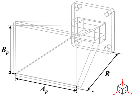
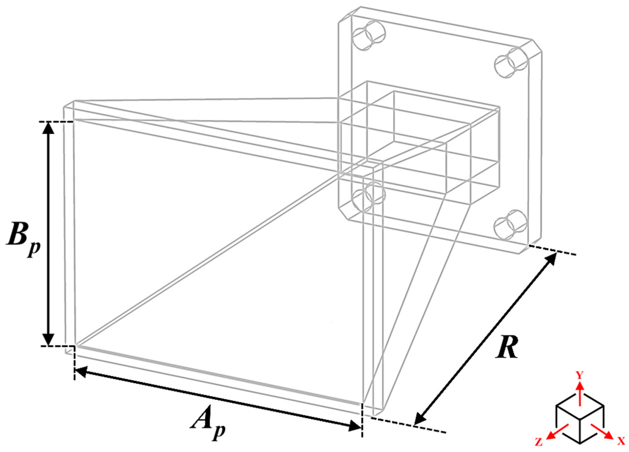
To mitigate these effects, a flared horn section is attached to the waveguide aperture, as illustrated in Figure 2. The horn provides a gradual transition from the waveguide cross section (a × b) to a larger aperture defined by (Ap × Bp), improving phase uniformity across the radiating aperture. The horn geometry is characterized by the aperture dimensions Ap and Bp, together with the flare radius R, which controls the expansion profile along the propagation direction. For a pyramidal horn, the flare angles in the E-plane and H-plane can be approximated as
Figure 2.
Geometrical configuration of the flared horn antenna, showing the aperture dimensions (Ap, Bp) and the flare radius (R) used to define the horn profile and aperture size.
The geometric parameters Ap, Bp, and R govern the aperture expansion rate and resulting phase distribution.
The gain of an aperture-type antenna is related to its effective aperture area and can be approximated by
where is the radiation efficiency, Aeff is the effective aperture area, and λ is the free-space wavelength. For the horn structure shown in Figure 2, the effective aperture is primarily controlled by the physical aperture dimensions (Ap × Bp) and the phase uniformity achieved through the flare radius R.
In this work, the horn geometry is selected using standard and well-established design relations to realize a target gain of approximately 15 dBi, providing a representative and repeatable WR-90 waveguide antenna configuration. The antenna is not intended as a novel design, but rather as a stable reference platform for investigating the impact of SLM on dimensional accuracy, electrical conductivity, and overall RF performance.
Accordingly, the primary focus of this paper is the experimental RF and material performance evaluation of SLM-fabricated WR-90 waveguide antennas, while the antenna geometry serves to ensure consistent electromagnetic behavior for meaningful comparison between simulation and measurement results presented in the subsequent sections.
3. Full-Wave Simulation Setup and Design Validation
Full-wave electromagnetic simulations are carried out using CST Microwave Studio to validate the antenna geometry and to establish a reference electromagnetic performance prior to fabrication. The simulations focus on evaluating realized gain and radiation characteristics of the proposed WR-90 waveguide horn antenna, with direct comparison to an open-ended WR-90 waveguide. The results presented in this section serve as a baseline for subsequent experimental evaluation of SLM-fabricated antennas.
3.1. Simulation Model and Reference WR-90 Geometry
The antenna geometry is modeled using standard WR-90 rectangular waveguide dimensions to ensure compatibility with commercially available waveguide components and measurement interfaces. The internal dimensions of the rectangular waveguide are a = 22.86 mm and b = 10.16 mm, consistent with widely adopted industrial standards [20,21]. This approach ensures that the simulated structure accurately represents practical off-the-shelf WR-90 hardware and facilitates a reliable transition from simulation to fabrication and measurement.
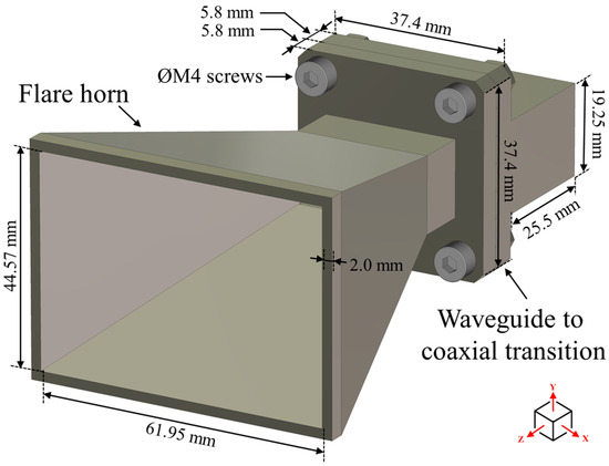
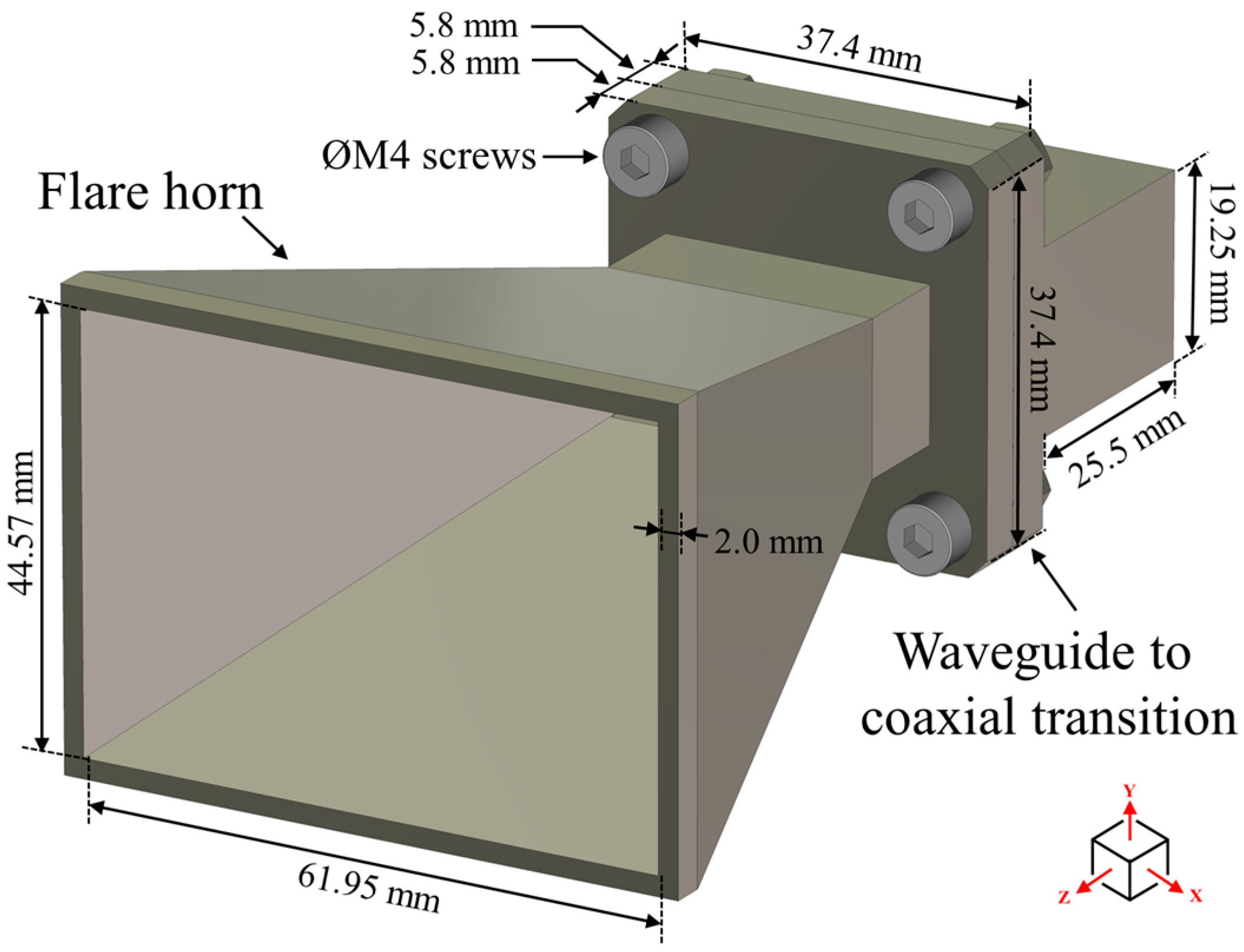
The optimized three-dimensional geometry of the WR-90 flared horn antenna used in the simulation is shown in Figure 3, including the waveguide-to-coaxial transition, flared radiating section, and mechanical mounting features. In the simulation model, all metallic components are initially treated as 316L stainless steel [22], which is the material used in the SLM process, to establish a reference electromagnetic response and to isolate the wave propagation and radiation behavior. Open (add space) boundary conditions are applied to emulate free-space radiation, and the computational domain is extended sufficiently beyond the antenna aperture to suppress artificial reflections from the boundaries.
Figure 3.
Optimized three-dimensional geometry of the WR-90 flared horn antenna used in the full-wave simulation, showing the coaxial-to-waveguide transition, flared radiating section, overall physical dimensions, and mechanical mounting features relevant to fabrication.
3.2. Coaxial-to-Open-Ended WR-90 Waveguide Simulation
In the first simulation stage, the coaxial-to-WR-90 waveguide transition is analyzed independently. A full-wave three-dimensional model is implemented in CST Microwave Studio, in which the SMA coaxial feed is explicitly modeled using a commercially representative connector geometry [23] consistent with practical implementations. This approach allows the transverse electromagnetic (TEM) mode supported by the coaxial line to be converted into the dominant TE10 mode within the waveguide while simultaneously capturing impedance mismatch effects arising from the connector geometry and probe excitation. By avoiding an idealized port excitation, the simulation provides a more realistic assessment of reflection behavior and mode conversion efficiency, enabling closer correspondence between simulated and measured results.
A frequency sweep covering the X-band range from 8.2 GHz to 12.4 GHz is performed to evaluate the reflection coefficient (S11) and to confirm stable single-mode propagation. This simulation stage verifies the effectiveness of the excitation mechanism and ensures that the open-ended WR-90 waveguide provides a well-matched guided-wave structure prior to integration with the flared radiating section.
3.3. Combined Coaxial-to-Open-Ended WR-90 Waveguide with Flared Antenna
In the final simulation stage, the flared radiating section is integrated with the coaxial-to-open-ended WR-90 waveguide to form the complete antenna structure. The two components are mechanically mounted using four M4 screws and secured with M4 nuts at the four corners. The flare geometry follows the design considerations described in Section 2 and is introduced to enlarge the effective aperture area and to improve the phase uniformity across the radiating aperture.
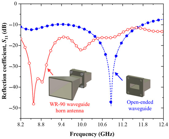
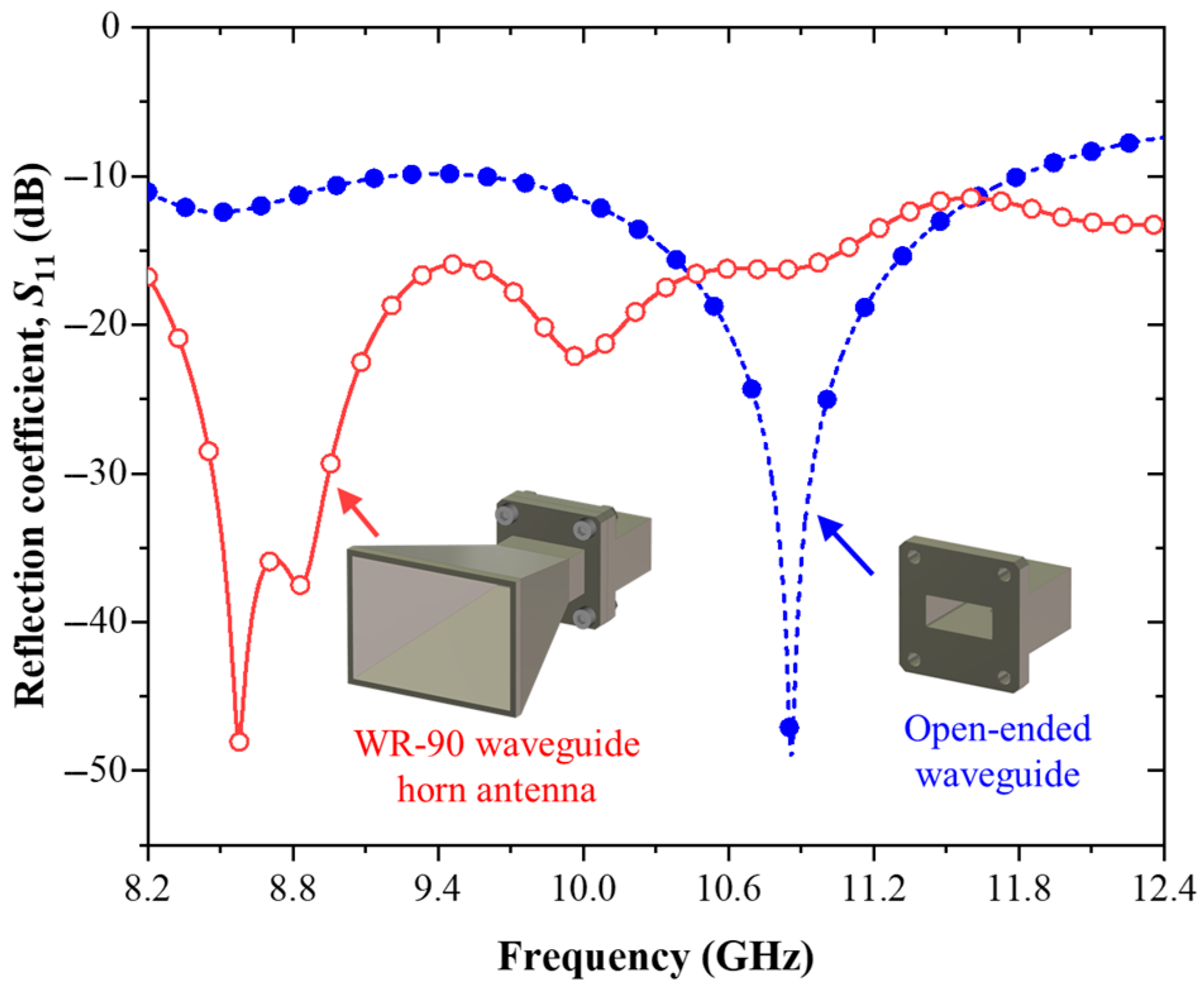
The simulated reflection coefficients of the open-ended waveguide and the WR-90 flared horn antenna are shown in Figure 4. For the flared horn antenna, the reflection coefficient remains below −10 dB across the entire operating band from 8.2 GHz to 12.4 GHz, confirming stable excitation of the dominant TE10 mode and effective impedance matching. In contrast, the open-ended waveguide exhibits degraded matching performance at higher frequencies, with the reflection coefficient increasing to approximately −9.5 dB above 11.6 GHz due to the abrupt aperture termination.
Figure 4.
Simulated reflection coefficient (S11) comparison between the open-ended WR-90 waveguide and the WR-90 flared horn antenna over the X-band frequency range from 8.2 to 12.4 GHz.
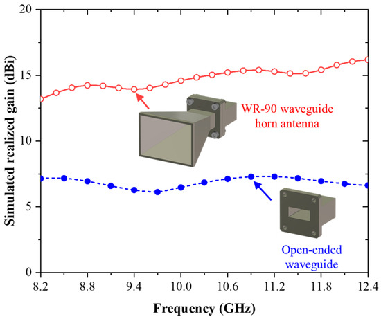
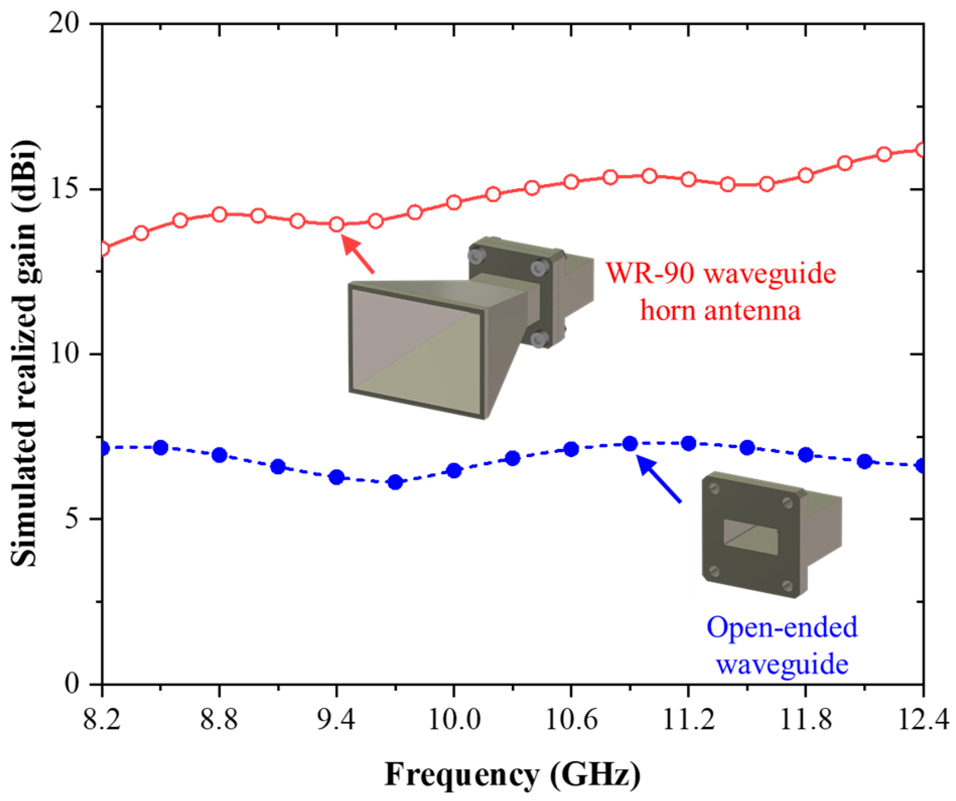
The simulated realized gain of both configurations is presented in Figure 5. The open-ended WR-90 waveguide exhibits a relatively low and stable gain, with an average value of approximately 7.5 dBi over the operating band. When the flared horn section is integrated, a substantial gain enhancement is observed. The realized gain of the WR-90 flared horn antenna increases from approximately 12.7 dBi at 8.2 GHz to 16.2 dBi at 12.4 GHz, following a monotonic upward trend with frequency. This behavior is consistent with aperture antenna theory, as the effective electrical size of the aperture increases with frequency. The resulting gain levels remain close to the intended design target of approximately 15 dBi, confirming that the selected geometry provides a stable and repeatable reference antenna configuration.
Figure 5.
Simulated realized gain comparison of the open-ended WR-90 waveguide and the WR-90 flared horn antenna across the X-band, demonstrating the gain enhancement achieved by the flared aperture.
3.4. Radiation Pattern Characteristics
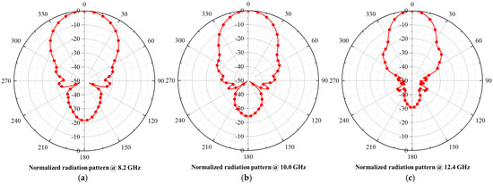
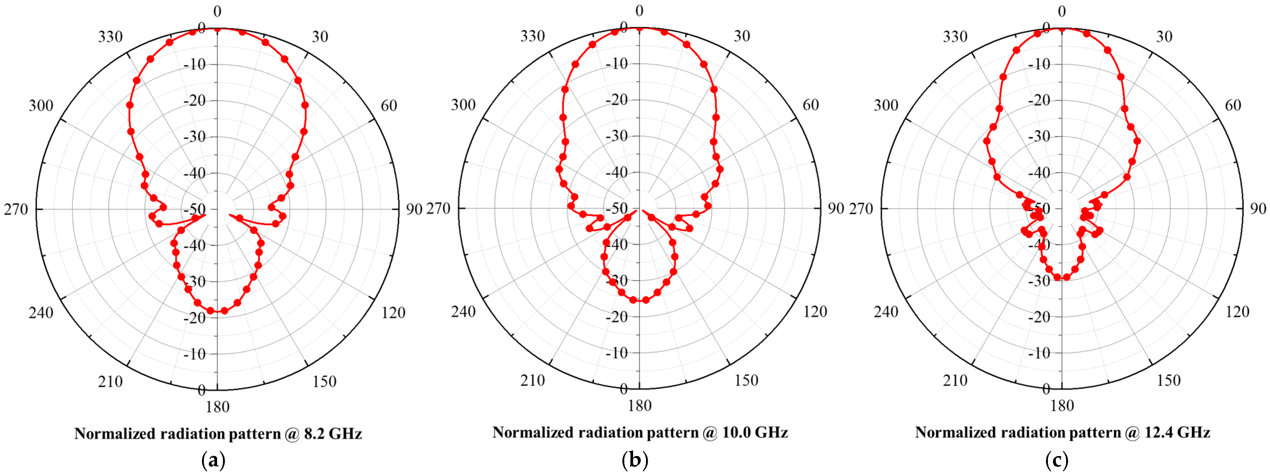
The normalized radiation patterns of the WR-90 flared horn antenna in the azimuth (XZ) plane are shown in Figure 6 at representative frequencies of 8.2 GHz, 10 GHz, and 12.4 GHz, corresponding to the lower, center, and upper portions of the operating band, respectively.
Figure 6.
Normalized radiation patterns of the WR-90 flared horn antenna in the azimuth (XZ) plane at representative frequencies of (a) 8.2 GHz, (b) 10 GHz, and (c) 12.4 GHz, corresponding to the lower, center, and upper portions of the X-band.
At 8.2 GHz, the antenna exhibits a half-power beamwidth (HPBW) of approximately 38.6°, with a sidelobe level of −21.7 dB. At 10 GHz, the beamwidth narrows to 32.7°, accompanied by a reduced sidelobe level of −24.3 dB.
At 12.4 GHz, further beam narrowing is observed, yielding an HPBW of 26.7° and a sidelobe level of −30.7 dB. This progressive improvement in directivity and sidelobe suppression with increasing frequency is consistent with the increasing electrical aperture size of the horn.
Across all sampled frequencies, the main radiation lobe remains aligned at 0°, indicating stable beam pointing and negligible beam squint throughout the X-band. These results confirm that the WR-90 flared horn antenna maintains consistent directional radiation characteristics suitable for reference measurements.
3.5. Scope and Limitations of the Simulation Model
It should be noted that the full-wave simulations presented in this section are performed using a simplified but physically representative material model. The finite electrical conductivity of the metal is taken into account by assigning conductivity values corresponding to the bulk material properties of the 3D-printing metal used in the SLM process, as specified in the material datasheet. The electrical conductivity of the 316L stainless steel used in the simulation is set to approximately 1.37 × 10⁶ S/m, derived from the reported bulk resistivity in the material datasheet [22]. This approach allows the simulations to reflect intrinsic ohmic losses associated with the printed metal.
However, surface roughness, microstructural inhomogeneity, and layer-by-layer fabrication effects inherent to the SLM process are not explicitly modeled in the simulation. These factors can introduce additional loss and scattering mechanisms that are difficult to capture accurately in full-wave electromagnetic solvers without extensive multi-scale modeling.
Accordingly, the simulated results represent a baseline electromagnetic response that includes bulk material conductivity but neglects surface roughness-induced effects. The electrical conductivity used in the simulation is derived from the bulk material properties reported in the datasheet [22]; however, it is recognized that the effective conductivity of SLM-fabricated metals is typically lower due to surface roughness, porosity, and microstructural inhomogeneity. Therefore, the use of bulk conductivity serves as an ideal reference baseline for quantifying fabrication-induced performance degradation. Any discrepancies observed between simulated and measured results are therefore primarily attributed to surface roughness, fabrication tolerances, and microstructural variations introduced during the SLM process. These effects are examined and discussed in detail based on experimental measurements in the subsequent sections.
4. SLM Fabrication and Material Composition Analysis
This section describes the SLM fabrication of the proposed WR-90 waveguide horn antenna and presents material characterization using SEM and EDX. The objective of this section is to document the practical fabrication workflow, verify the material integrity of the printed metal, and establish the suitability of the fabricated structure for X-band waveguide antenna applications prior to electromagnetic measurements.
4.1. Overview of the SLM Process
SLM is a powder bed fusion-based metal additive manufacturing technique capable of producing dense metallic components with complex geometries directly from digital models. The process begins with the creation of a three-dimensional computer-aided design (CAD) model, which is subsequently sliced into thin cross-sectional layers using dedicated preprocessing software.
During fabrication, a thin and uniform layer of metal powder is spread across the build platform inside a sealed chamber filled with an inert gas environment, typically nitrogen or argon, to suppress oxidation during laser exposure. A high-power laser beam is then selectively scanned across the powder bed, melting and fusing the metal particles according to the geometry defined for the current layer. The laser power, scan speed, hatch spacing, and scan strategy are carefully controlled to ensure complete melting and strong metallurgical bonding between adjacent tracks.
After each layer is completed, the build platform is lowered by a distance corresponding to the prescribed layer thickness, and a fresh powder layer is deposited. This layer-by-layer melting and solidification process is repeated until the entire component is fabricated. Upon completion, the printed part is allowed to cool gradually within the build chamber, resulting in a dense and mechanically robust metallic structure. Post-processing steps, such as powder removal, stress relief, and surface finishing, are typically required depending on application requirements.
4.2. SLM Fabrication Process and Parameters
The WR-90 waveguide horn antenna is fabricated using an industrial SLM system, BLT-A400 [24], employing a layer thickness of 0.05 mm. This layer thickness provides a practical balance between dimensional accuracy, surface quality, and fabrication efficiency suitable for microwave waveguide structures.
The antenna is printed using stainless steel 316L powder, which is selected due to its excellent corrosion resistance, mechanical robustness, and widespread adoption in metal additive manufacturing. According to the manufacturer’s specifications, the SLM-fabricated 316L stainless steel exhibits a typical dimensional tolerance of ±0.3 mm or within 0.4%, with a recommended wall thickness of 2.0 mm [25]. These tolerances are compatible with WR-90 waveguide dimensions and experimental X-band antenna evaluation.
The nominal mechanical and physical properties of the SLM-fabricated 316L stainless steel—such as tensile strength, elastic modulus, thermal conductivity, and electrical resistivity—are referenced from the manufacturer’s technical datasheets. The bulk electrical conductivity derived from the reported resistivity is used as an input parameter in the electromagnetic simulations, as discussed in Section 3. However, surface roughness-induced effects are not explicitly modeled in the simulation and are evaluated indirectly through experimental measurements.
In practical SLM fabrication, additional process-related constraints must be considered to ensure manufacturability and dimensional accuracy of microwave components. According to industrial design guidelines provided by [25] for metal additive manufacturing, the minimum wall thickness for stainless steel 316L structures is typically recommended to be in the range of 1.0–1.5 mm to ensure sufficient mechanical strength and complete fusion of powder particles. In addition, the minimum feature size is generally limited by the laser spot size and powder particle diameter, typically on the order of 0.3–0.5 mm, which restricts the realization of very fine geometrical details. The achievable dimensional tolerance for SLM-fabricated metal parts is commonly within ±0.1–0.2 mm, depending on geometry complexity and post-processing conditions. These fabrication constraints directly influence the design of waveguide structures, particularly for internal features such as narrow slots or thin walls, which must be carefully dimensioned to avoid incomplete melting or powder entrapment.
Furthermore, the layer thickness used in this work (0.05 mm) represents a trade-off between surface quality and fabrication time. While a smaller layer thickness improves surface finish and dimensional resolution, it increases the total build time due to the larger number of deposited layers. For the present WR-90 horn antenna, the total fabrication process, including layer-by-layer melting and subsequent cooling, typically requires several hours depending on scan strategy and build orientation. Additional time is required for post-processing steps such as support removal, powder cleaning, and mechanical finishing of critical interfaces. These process characteristics highlight that, although SLM enables complex three-dimensional geometries, it also imposes practical manufacturing constraints that must be carefully considered during antenna design and fabrication.
4.3. Fabrication Workflow and Post-Processing
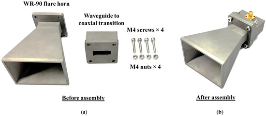
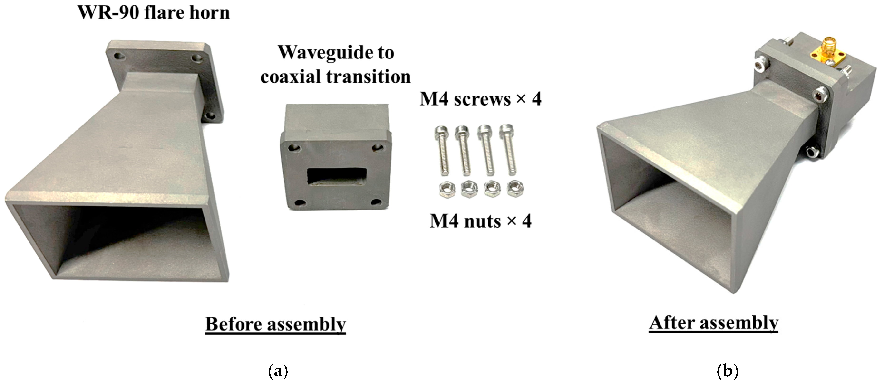
The individual components of the SLM-fabricated WR-90 waveguide horn antenna prior to assembly are shown in Figure 7a. The fabrication workflow of the WR-90 waveguide horn antenna follows the standard SLM printing sequence and is summarized here to clarify the practical implementation of the process.
Figure 7.
Photographs of the SLM-fabricated WR-90 waveguide horn antenna, consisting of the coaxial-to-waveguide transition and the flared horn section: (a) individual components before assembly and (b) fully assembled antenna structure.
First, the optimized three-dimensional antenna geometry obtained from the full-wave simulation results in Section 3 is prepared as a CAD model. This model is exported in standard STL format and subsequently sliced into thin cross-sectional layers using dedicated preprocessing software, defining the layer-by-layer fabrication sequence.
During fabrication, a thin and uniform layer of stainless steel 316L powder is deposited onto the build platform, which is located inside a sealed build chamber filled with an inert gas atmosphere to suppress oxidation of the metal powder. A high-power laser beam is then selectively scanned across the powder bed, melting and fusing the metal particles according to the geometry specified for the current sliced layer. The laser power, scan speed, and scan strategy are controlled to ensure complete melting and strong metallurgical bonding.
After completion of each layer, the build platform is lowered by an amount equal to the prescribed layer thickness (0.05 mm in this work), and a new powder layer is spread across the build area. This layer-by-layer melting and deposition process is repeated until the complete antenna structure is fabricated. Upon completion of the printing process, the fabricated part is allowed to cool gradually inside the build chamber to ensure solidification and structural stability.
Following printing, standard post-processing procedures are applied. These include removal of excess powder, detachment of support structures, and cleaning of the internal waveguide channel. Critical external interfaces, such as the waveguide flange and mating surfaces, are mechanically finished to ensure good electrical contact and compatibility with standard WR-90 measurement fixtures. No additional internal surface polishing is applied, allowing the fabricated antenna to represent a typical as-built SLM waveguide structure.
To further evaluate the fabrication accuracy of the SLM process, key geometrical parameters that strongly influence the radiation characteristics of the antenna were measured using a vernier caliper. The internal waveguide dimensions ( and ) were measured using the inner dimensions, while external dimensions, including the horn aperture dimensions ( and ), were measured using the outer dimensions of the caliper. The measured values were compared with the nominal CAD dimensions, and the corresponding percentage errors were calculated. The results, summarized in Table 1, show that all dimensional deviations are below 0.2%, indicating excellent agreement with the design values. These measured dimensional deviations, all below 0.2%, are well within the specified SLM fabrication tolerance of ±0.3 mm (or approximately 0.4%) reported in Section 4.2, confirming that the fabrication process achieves accuracy exceeding the nominal tolerance limits. These results confirm that the SLM fabrication process provides sufficient dimensional accuracy for X-band waveguide antenna applications, and that dimensional tolerances are not the dominant factor contributing to the observed RF performance degradation.
Table 1.
Dimensional comparison between the nominal (CAD) design and measured values of the SLM-fabricated WR-90 waveguide antenna.
4.4. Surface Morphology Observation Using SEM
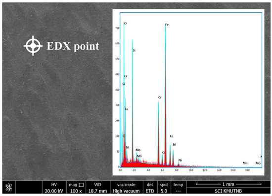
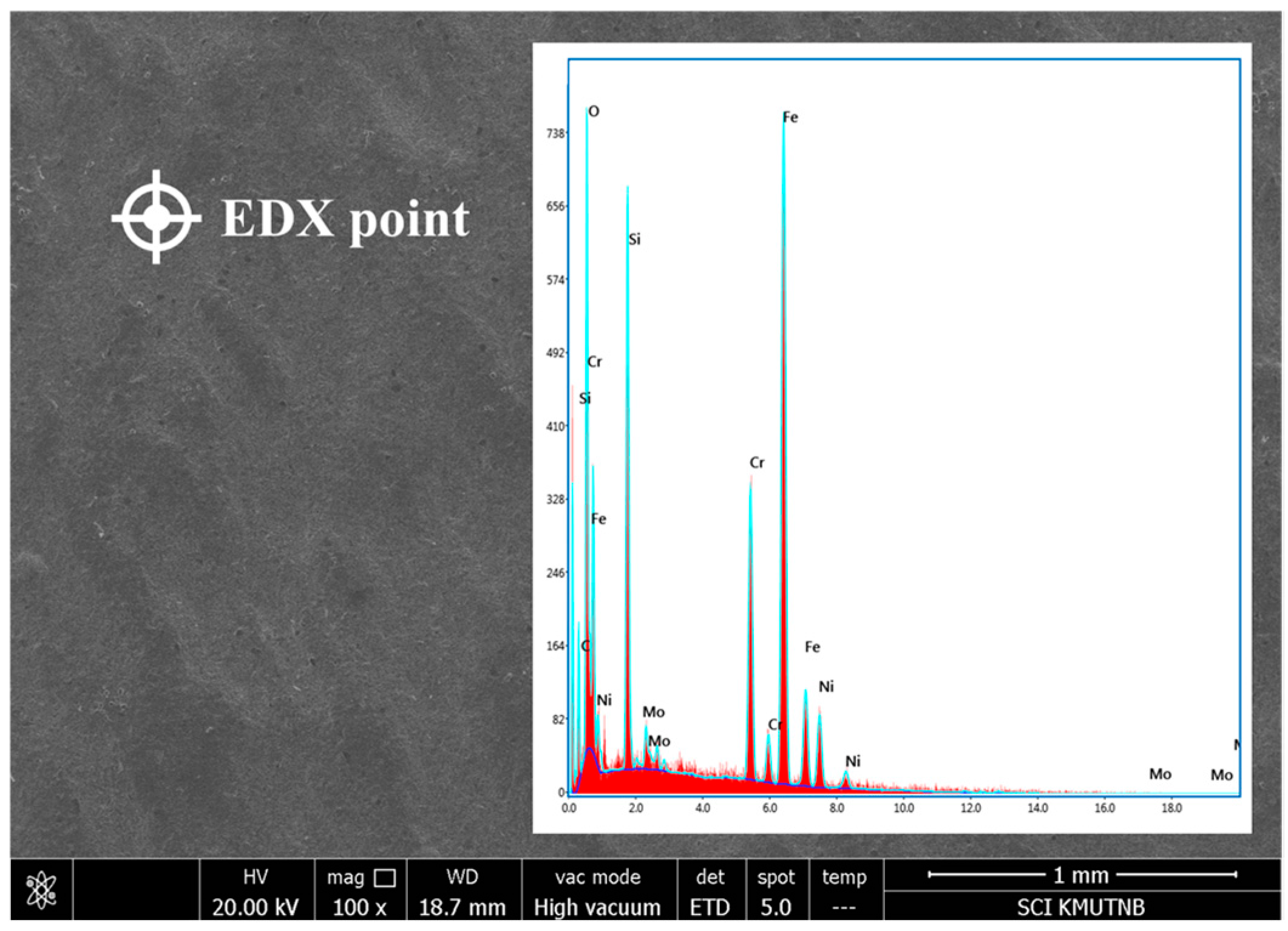
SEM is employed to qualitatively examine the surface morphology of the SLM-fabricated WR-90 waveguide horn antenna. SEM images are acquired at selected representative locations on the antenna surface, as shown in Figure 8, to observe surface features introduced by the layer-by-layer SLM fabrication process.
Figure 8.
Surface morphology and material composition analysis of the SLM-fabricated WR-90 flared horn antenna: scanning electron microscopy (SEM) image showing the characteristic surface features of the printed metal, with the EDX analysis point indicated, and the corresponding energy-dispersive X-ray spectroscopy (EDX) spectrum used to identify the elemental composition.
The SEM observations reveal characteristic surface features such as melt-pool textures, layer-wise morphology, and locally uneven surface regions resulting from rapid melting and solidification during laser scanning. No macroscopic cracks or delamination are observed in the inspected areas, indicating good structural integrity and adequate interlayer bonding. However, fine-scale asperities and partially fused surface features are evident, which are typical of SLM-fabricated stainless steel components.
It should be emphasized that the SEM analysis presented in this work is used solely for qualitative surface morphology observation. Quantitative surface roughness parameters, such as average roughness (Ra) or root-mean-square roughness (Rq), are not extracted from the SEM images. In addition, dedicated surface roughness measurement equipment, such as a contact profilometer or optical surface profiler, is not available in the authors’ laboratory at the time of this study. Typical surface roughness values (Ra) reported for SLM-fabricated 316L stainless steel are in the range of approximately 5–20 μm, depending on process parameters and post-processing conditions, which is consistent with the surface morphology observed in this work.
Nevertheless, the SEM observations provide valuable insight into the surface condition of the fabricated antenna and support qualitative discussion of potential surface-related loss mechanisms in the subsequent electromagnetic performance analysis.
The influence of surface roughness on conductor loss in microwave structures has been widely studied and can be described using established roughness correction models, such as the Hammerstad model and related formulations. These models indicate that increased surface irregularities effectively increase the surface resistance and current path length, resulting in higher attenuation in metallic waveguides. Although quantitative roughness parameters are not available in the present work, the observed surface features and the measured gain degradation are consistent with the expected behavior of SLM-fabricated metallic structures. Therefore, the SEM observations, combined with the quantitative efficiency analysis presented in Section 5.4, provide a physically consistent interpretation of fabrication-induced performance degradation.
The attenuation constant associated with conductor loss in rectangular waveguides can be expressed in a simplified form as
where is the surface resistance, is the frequency, is the permeability, and is the electrical conductivity of the conductor. This relationship indicates that conductor loss increases with frequency and decreases with higher conductivity.
To account for surface roughness effects, classical correction models such as the Hammerstad formulation introduce a roughness correction factor applied to the surface resistance:
where represents the surface roughness height and is the skin depth. This model shows that increasing roughness leads to higher effective surface resistance and therefore increased attenuation.
More advanced roughness models, such as the Huray model, provide a more detailed representation of multi-scale surface roughness by modeling conductive particles distributed on the surface. This approach is particularly relevant for additively manufactured metals with complex surface morphology; however, its application requires quantitative roughness parameters, which are not available in the present work.
4.5. Material Composition Analysis Using EDX
EDX is performed in conjunction with SEM analysis to verify the elemental composition of the SLM-fabricated antenna. The EDX analysis is conducted at the marked location indicated in Figure 8, and the corresponding spectrum is used to identify the constituent elements of the printed metal.
The EDX results reveal dominant peaks associated with iron (Fe), along with secondary peaks corresponding to chromium (Cr), nickel (Ni), and molybdenum (Mo). These elements are consistent with the nominal chemical composition of stainless steel 316L. Minor oxygen-related signals are also observed, which are commonly attributed to surface oxidation or residual oxide formation associated with metal powder processing and ambient exposure. No unexpected impurity elements are detected, indicating that the SLM fabrication process preserves the intended alloy composition without contamination.
4.6. Assembly of the Coaxial-to-Waveguide and Flared Antenna Structure
After fabrication and material composition verification, the antenna components are assembled to form the complete WR-90 waveguide horn antenna system. The assembly process consists of two primary stages: integration of the coaxial connector with the waveguide body, followed by attachment of the flared radiating section.
In the first stage, a standard SMA coaxial connector [23] is mechanically mounted to the coaxial-to-waveguide transition section of the SLM-fabricated structure, as illustrated in Figure 7a. The center conductor of the SMA connector is positioned to function as the excitation probe inside the rectangular waveguide, enabling efficient coupling of the transverse electromagnetic (TEM) mode from the coaxial line into the dominant TE10 mode of the WR-90 waveguide. Proper alignment and secure mechanical fastening are ensured to minimize impedance mismatch and maintain stable electrical contact during measurement.
In the second stage, the WR-90 waveguide body is assembled with the flared radiating section to form the complete antenna structure. The mating surfaces are aligned and fastened using M4 mechanical screws, ensuring accurate positioning and firm electrical contact across the joint interface. This modular assembly approach enables direct experimental realization of the simulated configuration described in Section 3.
The completed antenna assembly shown in Figure 7b is subsequently used for reflection coefficient, radiation pattern, and gain measurements, which are presented and discussed in the following section.
5. Experiment Setup and Measurement Results
This section presents the experimental setup and measured performance of the fabricated WR-90 waveguide antenna. The measurements include reflection coefficient characterization, radiation pattern measurement, and gain evaluation across the X-band frequency range. The measured results are compared with full-wave simulation outcomes to validate the antenna design and fabrication approach.
5.1. Antenna Measurement Setup and Calibration
The reflection coefficient and radiation measurements were performed using a PNA: N5227B vector network analyzer (VNA) [26] operating over a frequency range from 10 MHz to 67 GHz, enabling accurate characterization across the entire X-band. Prior to measurement, the system was calibrated using a full two-port short–open–load–through (SOLT) calibration to remove systematic errors associated with cables, connectors, and instrumentation and to reduce the influence of system noise.
The calibration established a well-defined reference plane at the coaxial connector interface, ensuring that the measured reflection coefficient accurately represents the input characteristics of the antenna. This full two-port calibration approach improved measurement stability and repeatability, particularly when comparing simulated and measured results.
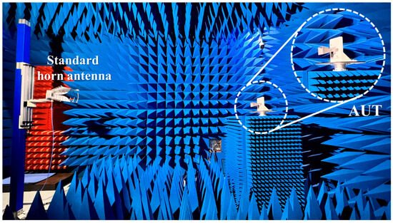
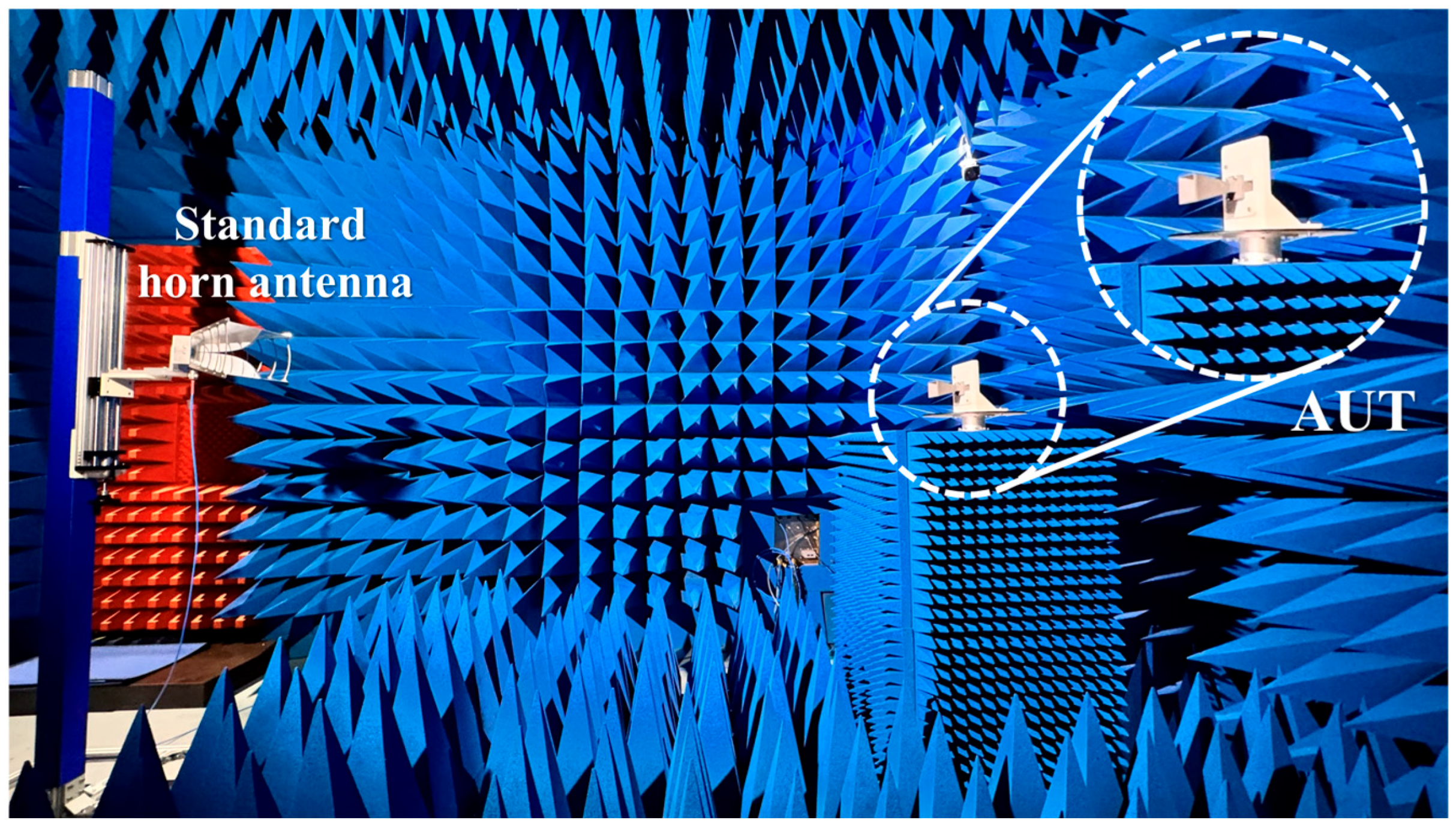
For radiation measurements, the antenna under test (AUT) was positioned at a distance satisfying the far-field condition, ensuring that the measured radiation patterns represent the true far-field characteristics of the antenna. A standard gain antenna [27] was selected and was used as the reference antenna. All measurements were conducted under controlled laboratory conditions inside an anechoic chamber, as illustrated in Figure 9, to suppress unwanted reflections and external electromagnetic interference. Multiple measurement sweeps were performed, and the averaged results were reported to mitigate the effects of random noise and connector repeatability.
Figure 9.
Experimental antenna measurement setup inside the anechoic chamber, illustrating the standard ridged horn antenna used as the transmitting antenna and the antenna under test (AUT) mounted on the rotation stage.
5.2. Reflection Coefficient Measurement Results
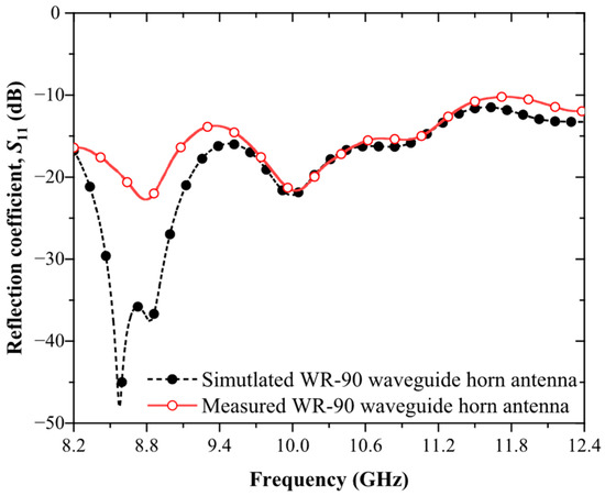
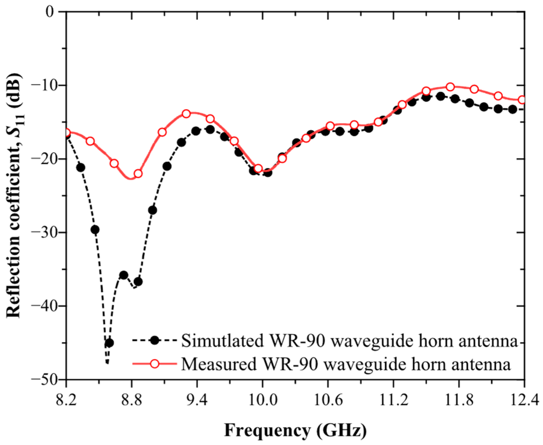
The measured reflection coefficient of the fabricated WR-90 waveguide horn antenna was compared with the simulated results in Figure 10. The measurements confirmed that the antenna operated effectively over the entire X-band frequency range from 8.2 to 12.4 GHz, with the reflection coefficient remaining below −10 dB across the full band.
Figure 10.
Comparison of the reflection coefficient (S11) of the WR-90 waveguide horn antenna obtained from full-wave simulation and experimental measurement over the X-band frequency range.
A pronounced impedance-matching minimum was observed at approximately 10.1 GHz, where the measured reflection coefficient reached −22.34 dB, indicating excellent impedance matching near the center of the operating band. The overall frequency trend of the measured response showed good agreement with the simulated results, validating the design of the coaxial-to-waveguide transition and the flared horn geometry.
Minor discrepancies between the simulated and measured reflection coefficients were primarily attributed to practical implementation effects not fully captured in the idealized simulation model. These included dimensional and assembly tolerances associated with the probe-based transition—such as probe penetration depth, longitudinal offset, and connector alignment—which could lead to small shifts in the impedance-matching frequency. In addition, the SLM fabrication process introduced surface roughness and material inhomogeneity in the 316L stainless-steel structure, as well as finite electrical contact resistance at the screw-mounted interface between the transition and horn sections. These non-ideal conductor effects increased effective RF loss and might reduce the depth of the reflection minimum, particularly toward the upper end of the X-band.
5.3. Radiation Pattern Measurement Results and Comparison
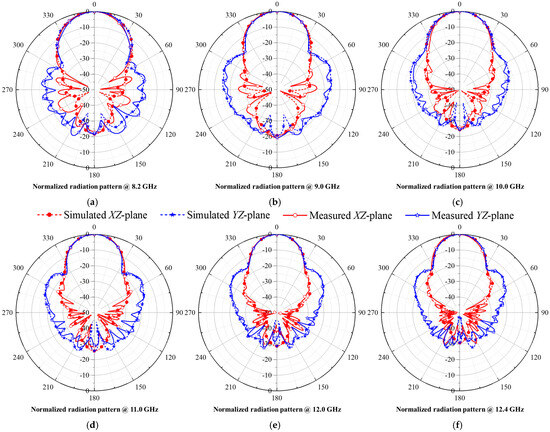
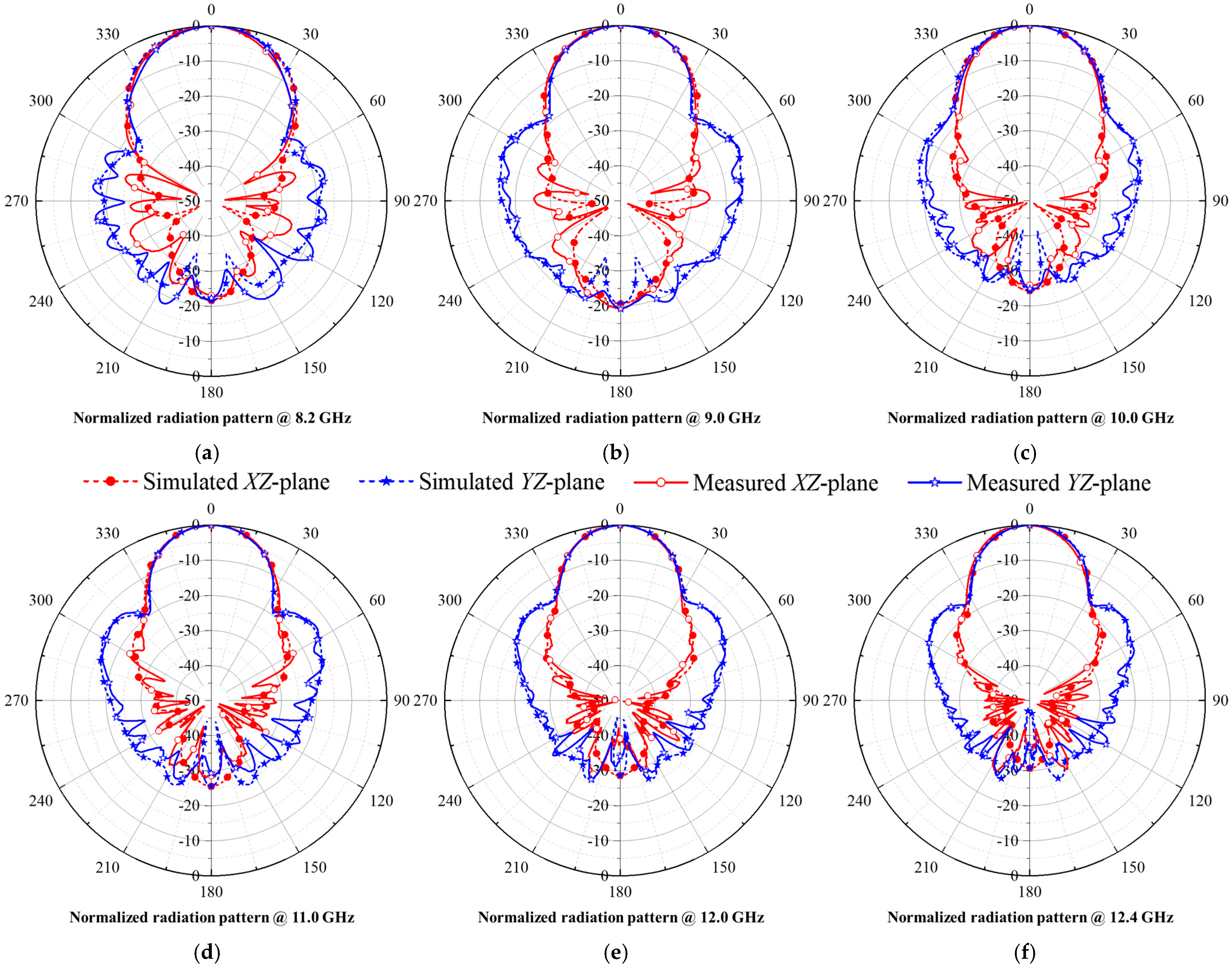
The radiation characteristics of the WR-90 waveguide horn antenna were evaluated through far-field measurements conducted inside an anechoic chamber. Normalized radiation patterns were measured at six representative frequencies across the X-band, namely 8.2, 9.0, 10.0, 11.0, 12.0, and 12.4 GHz, and comparisons between the simulated and measured results are presented in Figure 11a–f.
Figure 11.
Comparison of simulated and measured normalized radiation patterns of the WR-90 waveguide horn antenna in the azimuth (XZ) and elevation (YZ) planes at six representative frequencies: (a) 8.2 GHz, (b) 9.0 GHz, (c) 10.0 GHz, (d) 11.0 GHz, (e) 12.0 GHz, and (f) 12.4 GHz.
For each frequency, both simulated and measured radiation patterns were shown in the azimuth (XZ) plane and the elevation (YZ) plane, enabling direct comparison of directional behavior, beam symmetry, and frequency-dependent beam evolution. Across all frequencies, the measured radiation patterns exhibited a stable main-lobe direction aligned at broadside (0°), with beam shapes that closely followed the simulated predictions in both principal planes.
The HPBW values extracted from the simulated and measured radiation patterns were summarized in Table 2 for the azimuth (XZ) plane and Table 3 for the elevation (YZ) plane. In both planes, the measured HPBW decreased monotonically with increasing frequency, consistent with the simulated trend and aperture antenna theory. Quantitatively, the percentage deviation between simulated and measured HPBW values remained below approximately 4% across the entire X-band in both planes. The largest discrepancies were observed near the band edges and were attributed to fabrication tolerances, surface roughness inherent to the SLM process, and practical measurement uncertainties such as alignment and positioning.
Table 2.
Comparison of Half-Power Beamwidth (HPBW) Between Simulation and Measurement in the Azimuth (XZ) Plane.
Table 3.
Comparison of Half-Power Beamwidth (HPBW) Between Simulation and Measurement in the Elevation (YZ) Plane.
Overall, the close agreement between simulated and measured radiation patterns and HPBW values confirmed that the SLM-fabricated WR-90 waveguide horn antenna reproduces the intended radiation characteristics with high fidelity. These results demonstrate that metal additive manufacturing using SLM can achieve radiation performance comparable to conventional fabrication approaches for X-band waveguide antennas, while offering increased design flexibility and fabrication efficiency for rapid prototyping and experimental validation.
5.4. Realized Gain Measurement and Comparison
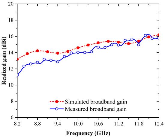
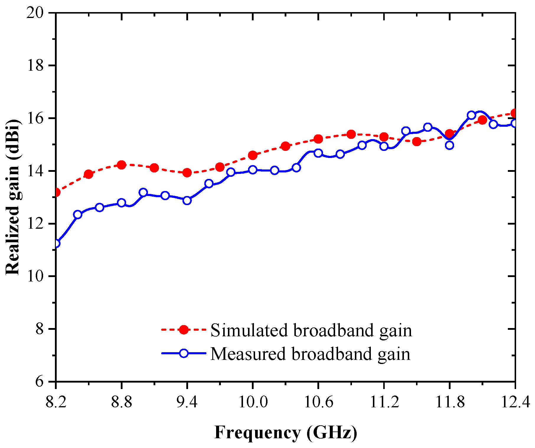
The realized gain performance of the WR-90 waveguide horn antenna was evaluated by comparing the measured results with full-wave simulation predictions, as illustrated in Figure 12. The comparison was conducted at broadside (0°) across representative frequencies within the X-band to assess the impact of fabrication and material effects on antenna performance.
Figure 12.
Comparison of the realized gain of the WR-90 waveguide horn antenna at broadside (0°) between full-wave simulation and experimental measurement across the X-band.
The simulated realized gain increased from approximately 13.2 dBi at 8.2 GHz to 16.2 dBi at 12.4 GHz, reflecting the expected behavior of a horn antenna as the effective electrical aperture size increases with frequency. The measured gain followed the same increasing trend, rising from approximately 11.2 dBi at 8.2 GHz to 15.8 dBi at 12.4 GHz. This consistency confirmed that the SLM-fabricated antenna preserves the intended aperture-based radiation mechanism.
A gain difference between simulation and measurement was observed across the band. At the lower end of the X-band (8.2–9.0 GHz), the measured gain is lower than the simulated value by approximately 1–2 dB. As the frequency increased, this difference gradually decreased, remaining within approximately 0.5 dB above 10 GHz. This trend indicated improved agreement between simulation and measurement at higher frequencies.
To provide a quantitative interpretation of this deviation, the gain difference was defined as
where and denote the simulated and measured realized gain, respectively.
The additional efficiency reduction associated with fabrication-induced losses was then estimated using
where represents the multiplicative efficiency factor relative to the simulated case.
For example, at 8.2 GHz, where the measured deviation was approximately
This indicated that the measured realized gain corresponds to approximately 63% of the simulated efficiency under the assumed bulk conductivity model. At higher frequencies, where the corresponding efficiency factor exceeded 0.89, indicating that fabrication-induced losses became comparatively less significant as frequency increased within the X-band.
To further interpret the observed performance deviation, it is useful to consider the interaction between conductor loss and aperture directivity.
In metallic waveguide structures, conductor attenuation generally increases with frequency. However, in the present horn antenna, the effective electrical aperture also increases with frequency, resulting in higher directivity. Consequently, although fabrication-induced loss remains present, its relative impact on realized gain became less significant at the upper end of the X-band.
The extracted efficiency factor therefore reflected the overall reduction in measured performance relative to the simulated reference, accounting for the combined influence of conductor loss, surface condition, and assembly-related effects rather than a single isolated mechanism. It should be noted that the extracted efficiency reduction factor represents the combined effect of multiple loss mechanisms, including conductor loss, transition loss, connector mismatch, assembly tolerances, and measurement uncertainty, rather than a single isolated contribution. The observed efficiency reduction was also consistent with established theoretical models describing the impact of surface roughness on conductor loss in microwave structures. In particular, roughness correction models, such as the Hammerstad formulation, indicated that surface irregularities increase the effective surface resistance and attenuation by modifying the current distribution along the conductor surface. Although quantitative roughness parameters were not available in the present work, the measured gain degradation and extracted efficiency reduction followed the expected trend for rough metallic surfaces produced by additive manufacturing. This provided further support that the dominant source of performance deviation was associated with surface-induced conductor loss rather than geometric or radiation-related effects.
For benchmarking purposes, it is noted that conventional WR-90 horn antennas typically exhibit realized gains in the range of approximately 13–17 dBi across the X-band, depending on aperture dimensions and design configuration. The measured gain of the proposed SLM-fabricated antenna (approximately 11.2–15.8 dBi) is in reasonable agreement with this range, with the observed reduction attributed to fabrication-induced effects such as surface roughness and finite conductivity. This comparison provides a practical reference for evaluating the performance of the SLM-fabricated antenna relative to conventional implementations.
For a rigorous comparison between SLM and conventionally manufactured (e.g., CNC-machined) waveguide antennas, both structures must share identical geometry, dimensions, and measurement conditions. In the present work, such a controlled comparison was not performed. Instead, the measured performance was compared with typical datasheet and literature values for CNC-machined WR-90 horn antennas [28,29], which are known to exhibit near-ideal conductor behavior. The observed gain deviation of approximately 2–3 dB can therefore be interpreted as fabrication-induced loss associated with the SLM process.
From a practical perspective, the extracted value at 8.2 GHz indicated a measurable but acceptable level of fabrication-induced efficiency degradation for X-band prototyping applications. While the reduction confirmed that surface condition and assembly effects influence RF performance, the antenna maintained stable radiation characteristics and expected gain trends across the operating band.
A more detailed partition of the observed loss into individual contributions, such as transition loss, conductor attenuation within the horn body, and surface roughness effects, would require additional calibration structures or dedicated simulation fitting procedures. Such analysis was beyond the scope of the present work and was identified as an important direction for future study.
The observed gain reduction was primarily attributed to practical factors not fully captured in the idealized simulation model, including finite electrical conductivity of the SLM-fabricated stainless steel, surface roughness introduced by the layer-by-layer manufacturing process, and additional losses associated with the coaxial-to-waveguide transition and mechanical assembly. Since radiation pattern shape and beamwidth remain consistent with simulation, the degradation was interpreted as predominantly conductor-related attenuation rather than geometric distortion of the radiating aperture.
From an analytical perspective, the conductor-related loss can be further interpreted using the concept of skin depth, defined as
where is the angular frequency, is the permeability, and is the electrical conductivity. As frequency increases, the skin depth decreases, resulting in current confinement to a thinner surface region and increased sensitivity to surface roughness. Consequently, deviations in surface quality and effective conductivity have a direct impact on attenuation in waveguide structures. The observed gain reduction and extracted efficiency factor were therefore consistent with increased effective surface resistance arising from both reduced conductivity and rough surface morphology in the SLM-fabricated structure.
Overall, the realized gain comparison, together with the quantitative efficiency estimation, demonstrated that the SLM-fabricated WR-90 waveguide horn antenna achieved performance levels close to full-wave simulation predictions, particularly in the mid-to-upper X-band. The results confirmed that SLM was a viable fabrication technique for producing waveguide horn antennas with competitive gain performance for practical microwave applications.
5.5. Practical Considerations and Implications for RF Applications
Based on the combined simulation, fabrication, and measurement results presented in this work, several practical considerations regarding the application of SLM for RF and microwave antenna systems can be identified.
One important consideration is the surface condition inherent to the SLM fabrication process. The layer-by-layer melting mechanism introduces surface features such as melt-pool boundaries and partially fused powder particles, as observed in the SEM analysis. Although these surface characteristics do not prevent satisfactory antenna operation at X-band frequencies, they can introduce additional conductor loss compared to conventionally machined waveguide structures. In practice, this effect may result in a modest reduction in radiation efficiency and realized gain. For higher-frequency or efficiency-critical applications, additional post-processing steps—such as internal surface polishing or conductive coating—may be required to further mitigate surface-related losses. These surface-related effects are consistent with the observed efficiency reduction discussed in Section 5.4, where the deviation between simulation and measurement reflects the cumulative influence of conductor-related loss mechanisms introduced by the SLM process. These observations are consistent with established theoretical models describing the impact of surface roughness on conductor loss in microwave structures. In particular, roughness correction models such as the Hammerstad formulation indicate that surface irregularities increase effective surface resistance and attenuation by modifying current distribution along the conductor surface. More advanced roughness models, such as the Huray model, can further account for multi-scale surface features and particle-based roughness typically observed in additively manufactured metals; however, their application requires quantitative roughness parameters (e.g., Ra or Rq), which are not available in the present work. Although quantitative roughness parameters are not available in the present work, the measured performance degradation and efficiency reduction are consistent with these well-known theoretical trends. Therefore, the observed gain deviation and extracted efficiency factor provide an indirect but physically consistent indication of roughness-induced conductor loss in the SLM-fabricated structure.
From an analytical standpoint, conductor loss in waveguide structures is strongly influenced by both electrical conductivity and skin depth. The skin depth is given by , indicating that reduced conductivity and increasing frequency lead to stronger current confinement near the surface. In SLM-fabricated metals, microstructural inhomogeneity and surface irregularities effectively reduce the conductivity and increase the effective surface resistance. These effects contribute to increased attenuation and are consistent with the observed efficiency reduction and gain deviation reported in this work.
Mechanical tolerances and assembly accuracy also play a critical role in determining RF performance. In this work, the antenna system consists of multiple assembled components, including the SMA coaxial connector, the WR-90 waveguide body, and the flared radiating section. Small misalignments at the coaxial-to-waveguide interface or imperfect electrical contact at waveguide joints can introduce additional impedance mismatch and measurement uncertainty. Careful mechanical alignment, precise mating of interfaces, and secure fastening are therefore essential to achieve repeatable and reliable RF measurements when using SLM-fabricated waveguide antennas.
Another important limitation arises from the geometric resolution constraints of the SLM process itself. Features with dimensions smaller than the minimum feature size supported by the SLM system—such as very narrow slots, thin gaps, or fine internal details—cannot be fabricated reliably. When the slot width or structural thickness approaches or falls below the practical resolution limit of the SLM technology, incomplete melting, powder trapping, or dimensional distortion may occur, leading to blocked openings or degraded electrical performance. As a result, RF structures that rely on extremely fine slots or sub-millimeter features may not be suitable for direct SLM fabrication without design modification or alternative manufacturing approaches.
Further practical consideration arises from the limitations of electromagnetic simulation models. While bulk electrical conductivity values derived from material datasheets are included in the simulations, surface roughness effects and microstructural variations inherent to the SLM process are not explicitly modeled. These factors can contribute to minor discrepancies between simulated and measured results. Incorporating more detailed material and surface models could further improve prediction accuracy; however, such approaches require advanced surface and microstructural characterization techniques that are beyond the scope of this study.
From a practical engineering perspective, the observed efficiency reduction and gain deviation remain within an acceptable range for X-band prototyping and experimental validation. For example, such efficiency levels remain acceptable in short-range radar sensing, laboratory measurement systems, or prototyping environments, where reduced radiation efficiency can be tolerated without significantly impacting overall system functionality. The results indicate that, although fabrication-induced losses are present, the SLM-fabricated antenna maintains stable impedance matching, radiation patterns, and overall functionality consistent with design expectations. This supports the suitability of SLM for rapid prototyping of waveguide antenna structures where moderate efficiency reduction can be tolerated. Consequently, the observed performance degradation should be interpreted as a system-level effect, and separation of individual loss contributions would require additional controlled measurements and calibration structures.
In addition, it should be noted that the present work is based on a single set of SLM fabrication parameters. Therefore, direct correlation between RF performance degradation and specific process parameters such as layer thickness, scan speed, or laser power cannot be established in this study. It should also be noted that a direct comparison between SLM and CNC fabrication techniques requires fabrication and measurement of identical antenna structures under controlled conditions. Such a study is beyond the scope of the present work and is identified as an important direction for future research. A more detailed investigation involving controlled variation in these parameters, as well as simulation-based approaches such as effective conductivity extraction through conductivity sweep, would enable improved understanding and quantitative separation of loss mechanisms. In particular, future work should include systematic fabrication of identical structures using varied SLM parameters (e.g., layer thickness, scan speed, and scan strategy), combined with direct surface roughness measurement (e.g., profilometry or optical methods) and post-processing studies such as internal polishing or conductive coating. These approaches would enable more rigorous correlation between fabrication conditions and RF performance degradation. A systematic investigation involving controlled variation in these parameters is required for quantitative process–performance correlation and is identified as an important direction for future work.
Furthermore, beyond the benchmark WR-90 horn structure used in this work, future studies should investigate more complex and integrated waveguide components, where the geometric flexibility of SLM provides clear advantages over conventional machining and where the proposed quantitative performance interpretation framework can be further validated.
Beyond the standard WR-90 horn antenna used in this work, SLM offers significant advantages in enabling the fabrication of complex and highly integrated microwave structures. These include embedded waveguide transitions, multi-port waveguide networks, and topology-optimized antenna geometries that are difficult or impractical to realize using conventional machining. Such capabilities enable compact, multifunctional designs and open new opportunities for advanced microwave system integration. The quantitative performance interpretation framework presented in this work can be extended to these more complex SLM-fabricated structures, providing a useful tool for evaluating fabrication-induced RF performance degradation in next-generation antenna systems.
Despite these considerations, the experimental results demonstrate that SLM-based metal additive manufacturing provides a robust and practical approach for fabricating WR-90 waveguide horn antennas operating in the X-band. The ability to realize complex three-dimensional waveguide geometries, integrated transitions, and customized antenna structures with reduced manufacturing complexity offers significant advantages for rapid prototyping and experimental validation. When appropriate design rules accounting for SLM resolution limits are followed, SLM-fabricated waveguide antennas can achieve performance levels suitable for practical RF and microwave applications.
6. Conclusions
This paper has presented the fabrication and experimental evaluation of a 316L stainless-steel WR-90 waveguide horn antenna manufactured using selective laser melting (SLM) technology and operating across the X-band (8.2–12.4 GHz). The antenna follows standard WR-90 waveguide propagation theory and incorporates a coaxial-to-waveguide transition and a flared radiating aperture to achieve stable aperture-based radiation. Full-wave electromagnetic simulations were used as a baseline reference to guide the design and to establish expected impedance and radiation performance.
Experimental measurements confirm stable impedance matching over the entire operating band, with the reflection coefficient remaining below −10 dB and reaching −22.34 dB near 10.1 GHz. The measured radiation patterns closely follow simulation predictions in both principal planes, with half-power beamwidth deviations below 4% across the band and consistent broadside beam alignment. The realized gain increases from approximately 11.2 dBi at 8.2 GHz to 15.8 dBi at 12.4 GHz, following the expected aperture-based trend.
A quantitative performance analysis was conducted by converting the simulation–measurement gain deviation into an equivalent efficiency reduction, enabling practical interpretation of conductor-related losses associated with the SLM-fabricated structure. The gain difference is most pronounced at the lower end of the X-band and decreases to within approximately 0.5 dB above 10 GHz, indicating that fabrication-induced losses remain moderate within this frequency range. This trend is also influenced by the difference between the bulk electrical conductivity assumed in simulation and the effective conductivity of the SLM-fabricated structure, which is reduced due to microstructural inhomogeneity and surface roughness. This behavior is consistent with surface roughness-induced conductor loss mechanisms described by established models (e.g., Hammerstad-type formulations and more advanced Huray-type approaches), although quantitative roughness parameters were not available in the present work. This quantitative interpretation provides a practical and physically meaningful approach for evaluating fabrication-induced electromagnetic degradation in additively manufactured waveguide antennas, particularly when direct material characterization is limited. However, it should be noted that quantitative surface roughness characterization was not performed in this work, and future studies incorporating direct roughness measurements and controlled variation in SLM process parameters will be essential for establishing a more rigorous process–performance correlation.
Material characterization using scanning electron microscopy (SEM) and energy-dispersive X-ray spectroscopy (EDX) verifies the structural integrity and elemental composition of the printed 316L stainless steel. Although surface morphology and fabrication tolerances inherent to the SLM process introduce measurable performance deviations compared to idealized simulations, these effects do not prevent reliable antenna operation for X-band applications.
From a practical engineering perspective, the observed efficiency reduction indicates that SLM-fabricated waveguide antennas remain suitable for X-band prototyping and experimental validation, where moderate performance degradation can be tolerated without compromising overall antenna functionality.
Overall, the results demonstrate that SLM-based metal additive manufacturing provides a practical and effective approach for WR-90 waveguide horn antenna fabrication. More importantly, the study establishes a benchmark experimental dataset and a quantitative performance interpretation framework that can be used to assess and compare fabrication-induced RF losses in SLM-based waveguide components. A direct comparison between SLM and conventionally manufactured (e.g., CNC-machined) antennas requires identical structures and measurement conditions, which is beyond the scope of the present study and is identified as an important direction for future work. Future work should include conductivity-sweep simulation to estimate effective electrical conductivity, as well as experimental methods to separate individual loss contributions, enabling more rigorous characterization of SLM-induced electromagnetic performance degradation. The combined experimental validation and quantitative performance interpretation presented in this work offer useful engineering insight into the RF implications of SLM fabrication and support the continued development of additively manufactured waveguide antennas for microwave applications.
Author Contributions
Conceptualization, N.C.; methodology, N.C., K.S. and K.B.; software, P.A.; validation, N.C., K.S. and K.B.; formal analysis, N.C.; investigation, K.S. and K.B.; resources, N.C.; data curation, K.S. and K.B.; writing—original draft preparation, N.C. and K.B.; writing—review and editing, N.C., K.B. and P.A.; visualization, P.A.; supervision, N.C. and P.A.; project administration, N.C.; funding acquisition, N.C. All authors have read and agreed to the published version of the manuscript.
Funding
This research was supported in part by the King Mongkut’s University of Technology North Bangkok, under Contract KMUTNB-67-KNOW-24.
Data Availability Statement
This research includes the original contributions offered in the article. Additional queries may be sent to the first and corresponding author.
Conflicts of Interest
The authors declare no conflicts of interest.
References
- Eiadkaew, S.; Boonpoonga, A.; Athikulwongse, K.; Kaemarungsi, K.; Torrungrueng, D. UAV Detection and Classification in Complex Environments Using Radar and Combined Machine-Learning Approaches. IEEE Trans. Microw. Theory Tech. 2025, 73, 5457–5470. [Google Scholar] [CrossRef] [Scilit]
- Phaebua, K.; Chudpooti, N.; Kittiwittayapong, S.; Lertwiriyaprapa, T.; Torrungrueng, D.; Chou, H.-T. One-Sixteenth Spherical Homogeneous Dielectric Lens Antenna Using Partially Reflective Surface for Size Reduction and High-Gain Radiation. IEEE Antennas Wirel. Propag. Lett. 2021, 20, 184–188. [Google Scholar] [CrossRef] [Scilit]
- Tao, J.; Meng, Y.; Zhengfeng, X.; Hui, N.; Zili, J.; Feng, Y. An X-Band Switched Energy Storage Microwave Pulse Compression System. IEEE Trans. Plasma Sci. 2019, 47, 4525–4529. [Google Scholar] [CrossRef] [Scilit]
- Li, C.; Lubecke, V.M.; Boric-Lubecke, O.; Lin, J. A Review on Recent Advances in Doppler Radar Sensors for Noncontact Healthcare Monitoring. IEEE Trans. Microw. Theory Tech. 2013, 61, 2046–2060. [Google Scholar] [CrossRef] [Scilit]
- Phakaew, T.; Oo, T.P.; Uzair, M.; Kowitwarangkul, P.; Chuchuay, P.; Yeetsorn, R.; Torrungrueng, D.; Chudpooti, N.; Chalermwisutkul, S. Additively Manufactured Mechanically Tunable Cavity Resonator for Broadband Characterization of Liquid Permittivity. Sensors 2025, 25, 7145. [Google Scholar] [CrossRef] [Scilit] [PubMed]
- Oo, T.P.; Phakaew, T.; Uzair, M.; Yeetsorn, R.; Akkaraekthalin, P.; Jeamsaksiri, W.; Chalermwisutkul, S. Ethanol Concentration Sensing Using a 3D-Printed Microwave Cavity Resonator. Metrology 2026, 6, 9. [Google Scholar] [CrossRef] [Scilit]
- Clemente, A.; Dussopt, L.; Sauleau, R.; Potier, P.; Pouliguen, P. Wideband 400-Element Electronically Reconfigurable Transmitarray in X Band. IEEE Trans. Antennas Propag. 2013, 61, 5017–5027. [Google Scholar] [CrossRef] [Scilit]
- Sangpet, P.; Chudpooti, N.; Akkaraekthalin, P. Additive Manufacturing of a Passive Beam-Steering Antenna System Using a 3D-Printed Hemispherical Lens at 10 GHz. Electronics 2025, 14, 3913. [Google Scholar] [CrossRef] [Scilit]
- Kong, G.; Li, X.; Wang, Q.; Zhang, J. A Wideband Reconfigurable Dual-Branch Helical Reflectarray Antenna for High-Power Microwave Applications. IEEE Trans. Antennas Propag. 2021, 69, 825–833. [Google Scholar] [CrossRef] [Scilit]
- Wu, S.; Li, J.; Chen, X.; Yan, S.; Zhang, X.Y. A Ka-Band SLM Printed Filtering Divider-Fed Magnetoelectric Dipole Antenna Array Using Embedded Gap Waveguide. IEEE Antennas Wirel. Propag. Lett. 2023, 22, 774–778. [Google Scholar] [CrossRef] [Scilit]
- Wu, S.; Li, J.; Li, Y.; Yan, S.; Zhang, X.Y. SLM Printed Dual-Band Dual-Polarized Shared-Aperture Filtering Antenna Array for Millimeter-Wave Integrated Sensing and Communication. IEEE Trans. Antennas Propag. 2024, 72, 2855–2860. [Google Scholar] [CrossRef] [Scilit]
- Li, J.; Wu, S.; Cao, Y.; Chen, X.; Li, Y.; Zhang, X.Y. SLM Printed Millimeter-Wave Multibeam Antenna Array Based on Filtering Butler Matrix. IEEE Trans. Antennas Propag. 2024, 72, 3813–3818. [Google Scholar] [CrossRef] [Scilit]
- Qi, H.; Liu, H. SLM Printed Wideband Filtering Antenna with Low Sidelobe and Controllable Bandwidth for K-Band Multibeam Applications. IEEE Trans. Antennas Propag. 2024, 72, 5331–5336. [Google Scholar] [CrossRef] [Scilit]
- Yuan, H.; Liu, Z.; Wang, L.; Si, L.; Sun, H.; Crupi, G.; Schreurs, D.; Bao, X. SLM Printed Wideband Circularly Polarized Multilayer Antenna Array with Reduced Impact by Manufacturing Imperfection. IEEE Access 2023, 11, 105368–105378. [Google Scholar] [CrossRef] [Scilit]
- Zhang, B.; Sun, H.; Wu, L.; Zhou, Y.; Yang, Y.; Zhu, H.; Cheng, F.; He, Y.; Huang, K. A Metallic 3-D Printed Airborne High-Power Handling Magneto-Electric Dipole Array with Cooling Channels. IEEE Trans. Antennas Propag. 2019, 67, 7368–7378. [Google Scholar] [CrossRef] [Scilit]
- Lv, S.; Li, J.; Cao, Y.; Yan, S.; Chen, J. SLM Printed Roll-Off Enhanced Wideband Millimeter-Wave ALTSA Array Based on Waveguide Mode Converter and Metallic Split Ring Resonator. IEEE Trans. Antennas Propag. 2026, in press. [Google Scholar] [CrossRef] [Scilit]
- Oosthuizen, H.; Gilmore, J. SLM 3D-Printed Active Phased Array for X-Band Satellite Communications. In Proceedings of the 2019 IEEE-APS Topical Conference on Antennas and Propagation in Wireless Communications (APWC), Granada, Spain, 9–13 September 2019; IEEE: New York, NY, USA, 2019; pp. 223–226. [Google Scholar] [CrossRef] [Scilit]
- CST. Microwave Studio; Computer Simulation Technology (CST): Framingham, MA, USA, 2017. [Google Scholar]
- Balanis, C.A. Antenna Theory: Analysis and Design, 3rd ed.; Wiley: Hoboken, NJ, USA, 2005. [Google Scholar]
- Pasternack Enterprises. WR-90 to SMA Female Waveguide Coax Adapter, 8.2–12.4 GHz (PE9804). Available online: https://www.pasternack.com/wr-90-sma-female-waveguide-coax-adapter-8.2-ghz-12.4-ghz-pe9804-p.aspx (accessed on 9 November 2025).
- A-INFO Inc. Right-Angle WR-90 to SMA Male Waveguide-to-Coaxial Adapter, 8.2–12.4 GHz (90WCASM-EP). Available online: https://www.ainfoinc.com/waveguide-components/waveguide-to-coaxial-adapter/right-angle-waveguide-to-coaxial-adapter/90wcasm-ep-right-angle-rectangular-waveguide-to-coaxial-adapter-8-2-12-4-ghz-wr90-to-sma-male-fep100-uer100 (accessed on 9 November 2025).
- JLC3DP. 316L Stainless Steel Material Properties. Available online: https://jlc3dp.com/help/article/316L-Stainless-Steel (accessed on 12 August 2025).
- Radiall. SMA Jack Flange-Mount Connector, 50 Ω (R125414000W). RS Components. Available online: https://export.rsdelivers.com/product/radiall/r125414000w/radiall-jack-flange-mount-sma-connector-50ω-solder/2956315 (accessed on 12 August 2025).
- Addvalue Technology. BLT-A400 Metal 3D Printer. Available online: https://addvalue.com.tr/EN/urun/23/blt-a400-3d-metal-printer (accessed on 12 August 2025).
- JLC3DP. 3D Printing Design Guidelines. Available online: https://jlc3dp.com/help/article/3D-Printing-Design-Guideline (accessed on 12 August 2025).
- Keysight Technologies. PNA-X Microwave Network Analyzer, N5227B. Available online: https://www.keysight.com/us/en/product/N5227B/pna-x-microwave-network-analyzer.html (accessed on 23 October 2025).
- A-INFO Inc. LB-10180-SF Broadband Horn Antenna, 1–18 GHz, 11 dBi Gain. Available online: https://www.ainfoinc.com/lb-10180-sf-broadband-horn-antenna-1-18-ghz-11db-gain-sma-female (accessed on 23 October 2025).
- Pasternack Enterprises. WR-90 Waveguide Horn Antenna Datasheet (PEWAN090-15SM). Available online: https://www.pasternack.com/images/ProductPDF/PEWAN090-15SM.pdf (accessed on 24 March 2026).
- A-INFO Inc. Standard Gain Horn Antenna, Model LB-90-15-C-SF, 8.2–12.4 GHz, 15 dB Gain. Available online: https://www.ainfoinc.com/antenna-products/horn-antennas/standard-gain-horn-antennas/lb-90-15-c-sf-standard-gain-horn-antenna-8-2-12-4-ghz-15db-gain-sma-female (accessed on 24 March 2026).

Disclaimer/Publisher’s Note: The statements, opinions and data contained in all publications are solely those of the individual author(s) and contributor(s) and not of MDPI and/or the editor(s). MDPI and/or the editor(s) disclaim responsibility for any injury to people or property resulting from any ideas, methods, instructions or products referred to in the content. |
© 2026 by the authors. Licensee MDPI, Basel, Switzerland. This article is an open access article distributed under the terms and conditions of the Creative Commons Attribution (CC BY) license.