


Abstract
Regarding the problems of fifth and seventh order characteristic harmonics existing in the operation of the dual three-phase permanent magnet synchronous motor, repetitive control is often used to improve the steady-state accuracy. However, traditional RC mostly adopts a fixed forward-learning gain and is set through trial-and-error methods, which requires a lot of time. Therefore, this paper proposes an improved repetitive control strategy based on fuzzy dynamic gain scheduling. This strategy precisely extracts the comprehensive distortion characteristic values of the target suppressed harmonics and the warning harmonics online; it designs a fuzzy adaptive adjustment mechanism to actively increase the gain to achieve rapid suppression when the target harmonic is severe, and rapidly reduce the gain to ensure the safety of operation when a low-frequency oscillation trend is detected. Simulation results show that the proposed method effectively reduces the total harmonic distortion of the current while maintaining the stability of the system and improves the harmonic suppression accuracy.
1. Introduction
In recent years, industries such as new energy vehicles [1], aerospace [2], and high-end intelligent manufacturing [3] have witnessed rapid development. The performance requirements for core driving components in these fields have been continuously increasing. Not only do they need to meet the demands for high power density and high reliability, but they also have higher requirements for the control accuracy, operating efficiency, and anti-interference ability of the motor drive system. Against this backdrop, the dual three-phase permanent magnet synchronous motor (DTP-PMSM), with its outstanding advantages of high power density, low torque pulsation, and strong fault tolerance, has gradually become the preferred driving motor in these fields and has been widely promoted and applied. However, due to the winding coupling effect [4], the nonlinear electromagnetic characteristics of the motor itself [5], and the comprehensive influence of the power converter [6], characteristic harmonics such as fifth and seventh harmonics are prone to occur during operation. These harmonics can lead to an increase in copper loss and iron loss of the motor, a significant decrease in operating efficiency, and seriously affect the control accuracy and torque stability of the motor, thereby restricting the full realization of its high-performance potential. Therefore, addressing the issue of current harmonic suppression for the dual three-phase permanent magnet synchronous motor and developing efficient and reliable control strategies has become a core prerequisite for ensuring its stable application in the high-end field.
Regarding the harmonic problem of the dual three-phase permanent magnet synchronous motor, the current mainstream harmonic control methods can be classified into two categories: motor body optimization and improvement in motor control strategies. Among them, the common methods in the motor body optimization category focus on fundamentally weakening the harmonics, including stator slotted and pole inclined, optimization of permanent magnet shape and magnetic circuit parameters, topology reconstruction of stator windings, etc. Although these methods can improve the sine degree of the air gap magnetic field and reduce the generation of harmonics, they often require sacrificing the power density of the motor and significantly increasing the complexity and cost of the processing technology [7]. The improvement in motor control strategies, with its advantages of strong flexibility and wide adaptability, has become the mainstream direction for suppressing harmonics in dual three-phase motors. Common methods include harmonic voltage compensation method, multi-rotational PI control [8], complex vector PI control [9], active disturbance rejection control [10], proportional resonance (PR) control [11], repetitive control (RC) [12], etc. Among these control methods, repetitive control demonstrates unique advantages—based on the internal model principle, it can remember and utilize the harmonic error from the previous cycle through the periodic delay link to precisely suppress the periodic characteristic harmonics generated during the operation of the dual three-phase motor, effectively reducing the control loop and providing a more efficient technical path for harmonic suppression of dual three-phase motors, and has also become a research hotspot in this field.
Repetitive control can effectively suppress periodic harmonics. However, when applied in actual motor drive systems, it still faces several problems. Firstly, the fixed sampling frequency is difficult to match the harmonic frequencies that vary with the rotational speed, resulting in fractional-order delay in the controller, causing resonance frequency deviation, and severely weakening the suppression performance. To address this issue, Reference [13] proposes an improved repetitive controller, whose core is to use Lagrange interpolation to approximate the fractional-order delay link, making the resonant frequency of the controller more consistent with the actual harmonic frequency of the motor; at the same time, this study moves the low-pass filter out of the internal model of the traditional repetitive control and designs a phase compensator to ensure system stability, thereby enhancing the suppression ability of current harmonics. Reference [14] proposes a fractional-order repetitive controller based on geometric constraint optimization. This method converts the optimization problem of interpolation coefficients into a geometric constraint problem and reconfigures the coefficients while introducing a combined filter outside the feedback loop to achieve less resonance frequency deviation and a peak distribution more in line with the harmonic energy law, effectively improving the system stability and current harmonic suppression performance over the full speed range. Secondly, the forward gain of traditional repetitive controllers is usually a fixed value, and its size needs to be balanced between suppressing speed and system stability: a too small gain leads to slow convergence and insufficient suppression effect; a too large gain may accelerate the suppression of characteristic sub-harmonics but may amplify other non-characteristic sub-harmonics, thereby threatening system stability. To enhance the robustness of the system under parameter uncertainty and disturbances, Reference [15] proposes a discrete-time sliding mode repetitive control. This method combines the strong robustness of sliding mode control with the periodic error suppression ability of repetitive control to enhance the tracking accuracy and stability of the servo system. Additionally, to overcome the fractional delay problem of traditional RC when the motor speed changes, Reference [12] proposes a repetitive controller based on average period delay. By synchronizing the update trigger mechanism of the internal model with the real-time electrical angle of the motor, it dynamically adjusts its delay period.
In conclusion, although the existing improvement methods have made progress in addressing the issue of fractional delay and enhancing robustness, they have paid less attention to the online optimization of the forward gain of the repetitive controller. The fixed gain strategy is difficult to achieve a dynamic optimal balance between rapid suppression of harmonics and stable operation of the system. Therefore, intelligent adaptive gain scheduling has become an important direction for improving the performance of controllers. Researchers have explored related strategies from various perspectives, mainly falling into the following two categories: 1. Structural gain scheduling: This method does not directly adjust the gain coefficient but achieves the “scheduling” of gain effects at the system level by combining with other control strategies. For example, combining repetitive control with active disturbance rejection control, using the expansion state observer of the latter to estimate and compensate for the total disturbance in real time, thereby reducing the reliance on the high gain of the repetitive controller and indirectly achieving the reduction of “gain requirements” during dynamic processes. This composite structure optimizes the “equivalent gain” characteristics of the system through the collaborative work of the controller [16]. 2. Parametric gain scheduling: This method directly adjusts the system parameters online. An advanced idea is to draw on the “on-demand scheduling” concept from event-triggered control [17]. For example, by designing an adaptive event-triggering mechanism and switching function, the control law can be updated only when the tracking error or system state change reaches a specific threshold [18]. Among the various methods for implementing online intelligent parameter scheduling, fuzzy logic control has been widely applied in complex system control due to its independence from precise mathematical models and its proficiency in handling nonlinearity and uncertainty. For instance, for discrete-time nonlinear systems where the states cannot be directly measured, an observer-based fuzzy control scheme has been proposed. This scheme constructs the closed-loop system using the descriptor system method and ensures the stability and specified performance indicators of the system based on Lyapunov theory [19]. In more complex multi-region power system load frequency regulation, in the face of uncertainties and nonlinearity brought by network attacks, a distributed control strategy based on interval type-2 fuzzy models have been proven to effectively enhance the system’s resilience [20]. These works indicate that embedding the decision-making and reasoning capabilities of fuzzy logic into the parameter scheduling link of the controller is an effective way to deal with system uncertainties and enhance overall robustness. Therefore, this paper proposes an improved repetitive control strategy based on fuzzy dynamic gain scheduling for the current harmonic suppression problem of dual three-phase PMSM. This strategy aims to extract the distortion characteristics of the target harmonic and the warning harmonic online, design a fuzzy adaptive mechanism, and adjust the repetitive control gain in real-time and dynamically, thereby enhancing the suppression speed when harmonics are severe and rapidly reducing the gain to ensure safety when a risk of instability is detected. Ultimately, it achieves a coordinated improvement in harmonic suppression accuracy and global stability of the system.
2. Analysis of Current Harmonics in Dual Three-Phase Permanent Magnet Synchronous Motors
In the dual d-q rotating coordinate system, disregarding the mutual inductance between the two sets of windings, the voltage equation of the dual three-phase permanent magnet synchronous motor can be expressed as Equation (1).
Among them, , , and represent the voltages of the d1 axis, q1 axis, d2 axis and q2 axis, respectively; , , and represent the currents of the d1 axis, q1 axis, d2 axis and q2 axis, respectively; R is the stator resistance; and are the d-axis and q-axis inductances; represents the external disturbance of the corresponding axis; is the electrical angular velocity.
The magnetic linkage equation can be expressed as Equation (2).
where and represent the d-axis and q-axis magnetic fluxes of the corresponding windings; and represent the d-axis and q-axis permanent magnet magnetic fluxes of the corresponding windings.
Taking into account magnetic saturation and stator slot effects will cause harmonic disturbances in the permanent magnet magnetic fluxes. The permanent magnet magnetic fluxes can be expressed as Equation (3).
Among them, represents the DC component of the magnetic flux; and are the amplitudes of the fifth and seventh harmonic components of the magnetic flux on the d-axis and q-axis, respectively. The inductance can be expressed as
Among them, , , , are the direct component and sixth harmonic self-inductance amplitudes of the d-axis and q-axis.
Furthermore, the distortion voltage disturbance caused by the dead zone effect of the inverter can be expressed as
Among them, and are the voltage errors of the d-axis and q-axis; is the DC bus voltage of the inverter; is the dead time; is the sampling time.
Then, the output current of the motor can be expressed as
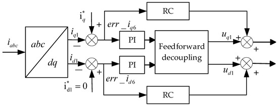
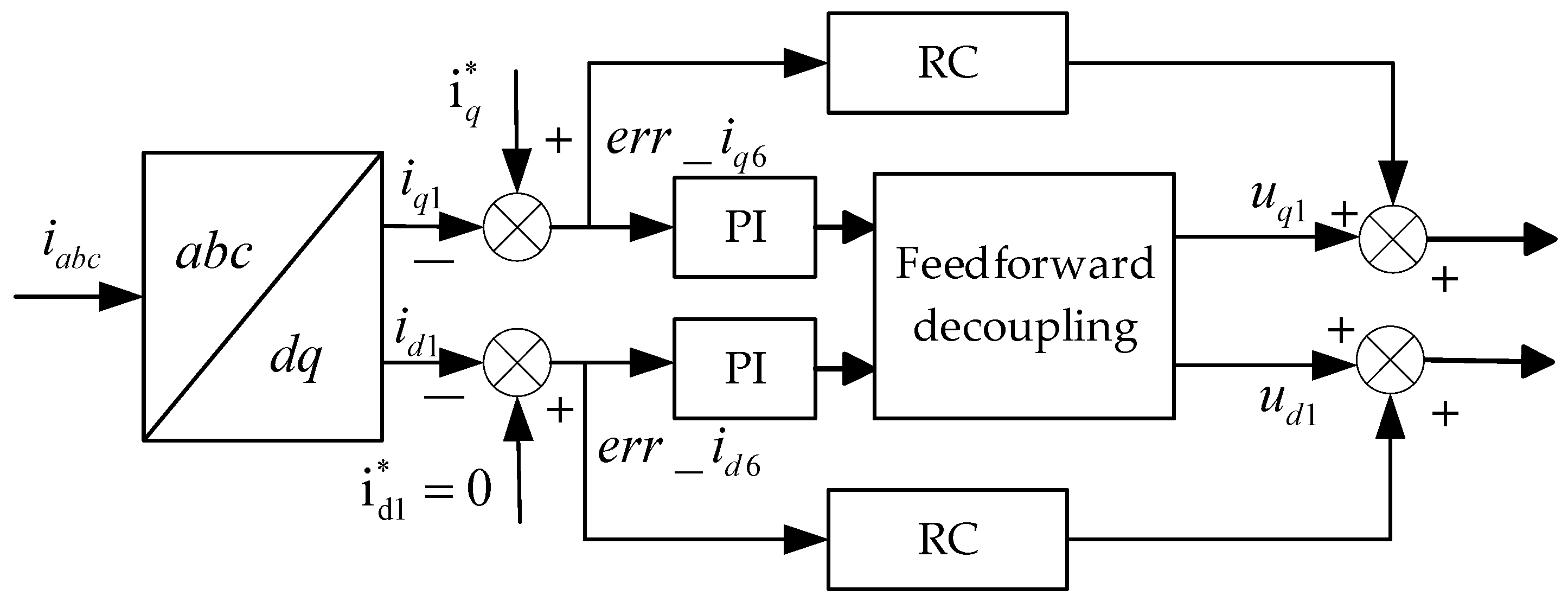
The block diagram of the control strategy system adopted in this paper is shown in Figure 1. Considering that the traditional PI controller has a relatively weak ability to track and suppress periodic harmonic signals, while repetitive control can achieve high-precision and error-free tracking of periodic signals based on the internal model principle, in this paper, repetitive control and PI control are designed in parallel to construct a composite current loop controller in order to balance the dynamic response speed of the system and the steady-state harmonic suppression accuracy.
Figure 1.
Current loop control block diagram.
3. Design of Repeat Controller Based on Pre-Filter
3.1. The Repetitive Controller Structure of the Pre-Filter
The core principle of the repetitive controller is based on the internal model principle. It can periodically store and iteratively correct the error between the given signal and the feedback signal within the historical cycle, thereby achieving precise suppression of repetitive AC errors in each cycle. In response to the harmonic characteristics of the permanent magnet synchronous motor and to reduce the inherent delay points of the internal model, this paper adopts an internal model structure with a control frequency of six times the fundamental frequency. The delay points of this structure are
Here, represents the sampling frequency of the system, and represents the fundamental frequency of the motor current.
The existence of the internal model introduces poles located on the unit circle to the control system, which reduces the system stability. Therefore, to enhance the system stability, an auxiliary compensator and a low-pass filter are usually introduced in the repetitive controller.
In practical applications, the position of the filter has a significant impact on the resonant characteristics of the repetitive control internal model. Existing research [13] has shown that, compared to embedding the filter in the inner loop, moving the filter outside the loop does not change the inherent resonant frequency of the internal model, and the phase characteristics remain consistent with the input, effectively ensuring the harmonic suppression accuracy and stability of the system.
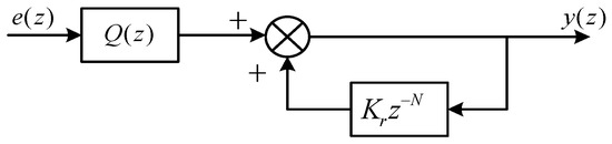
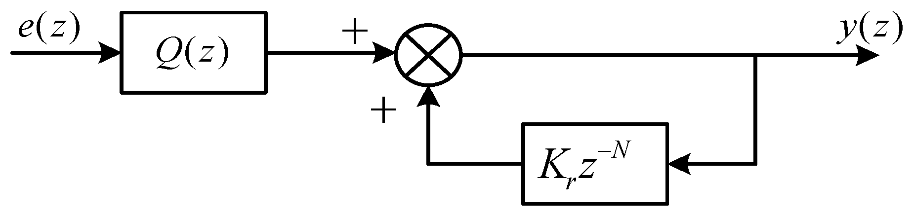
Therefore, this paper adopts a repetitive control structure based on a pre-filter as shown in Figure 2, and its transfer function is
Figure 2.
Block diagram of the repetitive control structure based on the pre-filter.
Furthermore, since traditional repetitive control exhibits a semi-resonant peak near 0 Hz, it is prone to causing error accumulation in the low-frequency range, thereby threatening the steady-state accuracy and stability of the system [14]. Therefore, in this paper, a band-pass filter composed of a low-pass filter and a high-pass filter is used to extract and suppress the harmonic features.
3.2. Fractional-Order Delay Compensation Based on Lagrange Interpolation Method
In practical digital control systems, due to the variation in motor speed, the sampling frequency often cannot be maintained as an integer multiple of the fundamental frequency, resulting in non-integer values for the delay steps of the repetitive controller. Direct rounding can cause resonance frequency shifts, severely weakening the harmonic suppression performance. Therefore, in this paper, the Lagrange interpolation method is used to approximate the fractional-order delay link. Through polynomial fitting, precise phase compensation is achieved to ensure that the resonance peak always maintains a high degree of matching with the target harmonic frequency within a wide range of rotational speeds.
In Equation (9), , are interpolation points, is the order of Lagrange interpolation, and the larger the value of , the more accurate the interpolation is, but the corresponding computational load will also be greater. To balance accuracy and speed, this paper adopts .
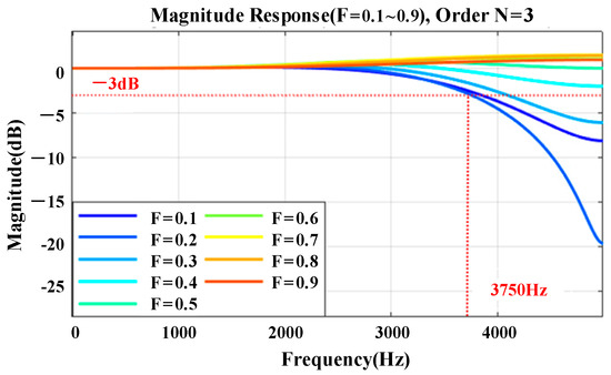
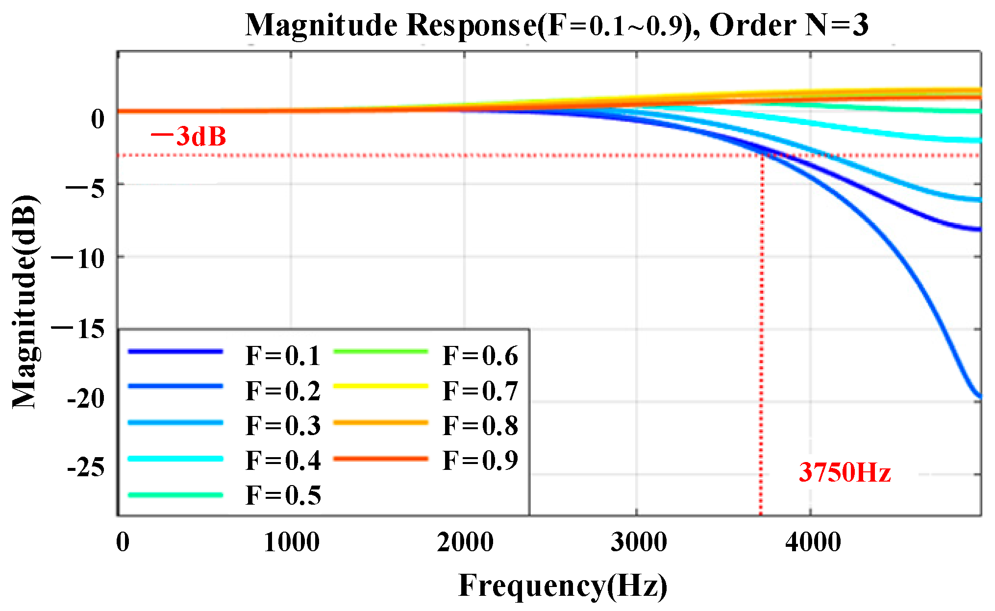
Figure 3 shows the amplitude–frequency characteristic curve of the third-order Lagrange interpolation polynomial of F from 0.1 to 0.9. The bandwidth is 3750 Hz. Therefore, when the harmonic frequency is lower than 3750 Hz, this method can achieve a good approximation for the fractional-order delay link.
Figure 3.
The amplitude–frequency characteristic curve of the Lagrange interpolation polynomial.
3.3. Stability Analysis
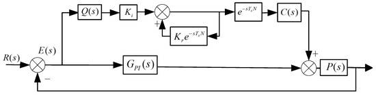
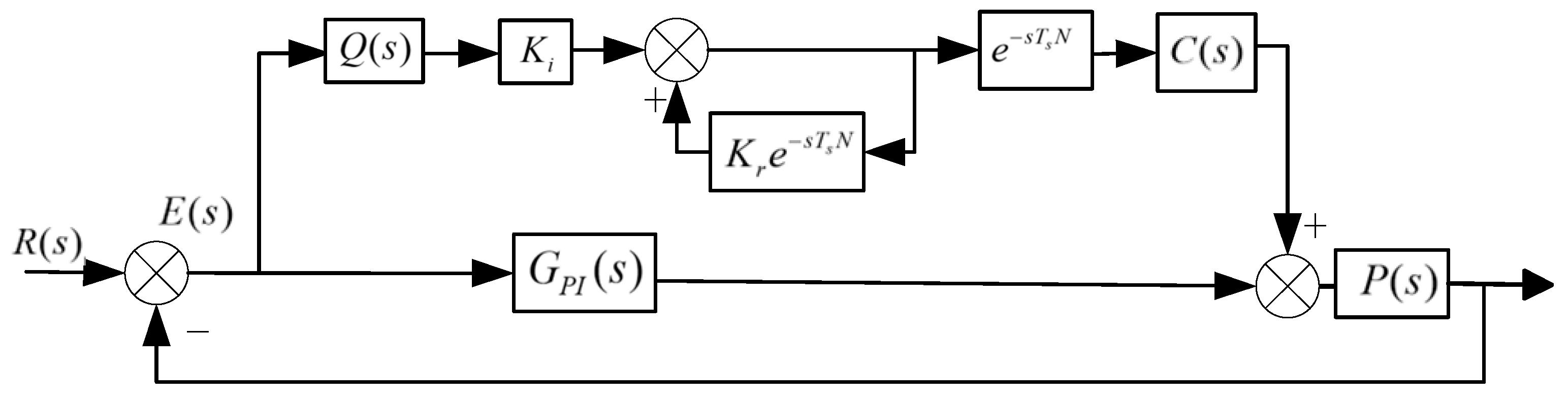
To ensure that the designed repetitive controller can be reliably applied to the DTP- PMSM drive system, the closed-loop stability will be analyzed theoretically. Figure 4 shows the current loop structure block diagram adopted in this paper. Here, represents the phase compensation link, is the gain coefficient, and is the compensation step number. The error transfer function is
Figure 4.
Current loop structure block diagram.
Then, the closed-loop characteristic equation is expressed as
In order to utilize the small gain theorem for stability analysis, we need to rewrite the characteristic equation in the standard form of . Therefore, by dividing both sides of Equation (11) by , we obtain
According to the small gain theorem, for a feedback system with a delay link, if the system is to be stable at all frequencies , then the magnitude of the loop gain of the closed-loop circuit must be less than 1. Due to the fact that the amplitude of the delay component in the frequency domain satisfies , the stability criterion of the system is transformed into the requirement that the magnitude of is less than 1 throughout the entire frequency range. Thus, we obtain Equation (13):
At the same time, design to make the phase shift in the mid- and low-frequency bands approximately zero, and at the same time, ensure the phase lag in the high-frequency end does not exceed 90°.
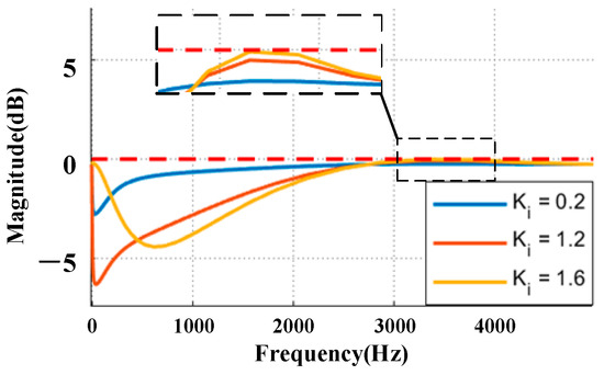
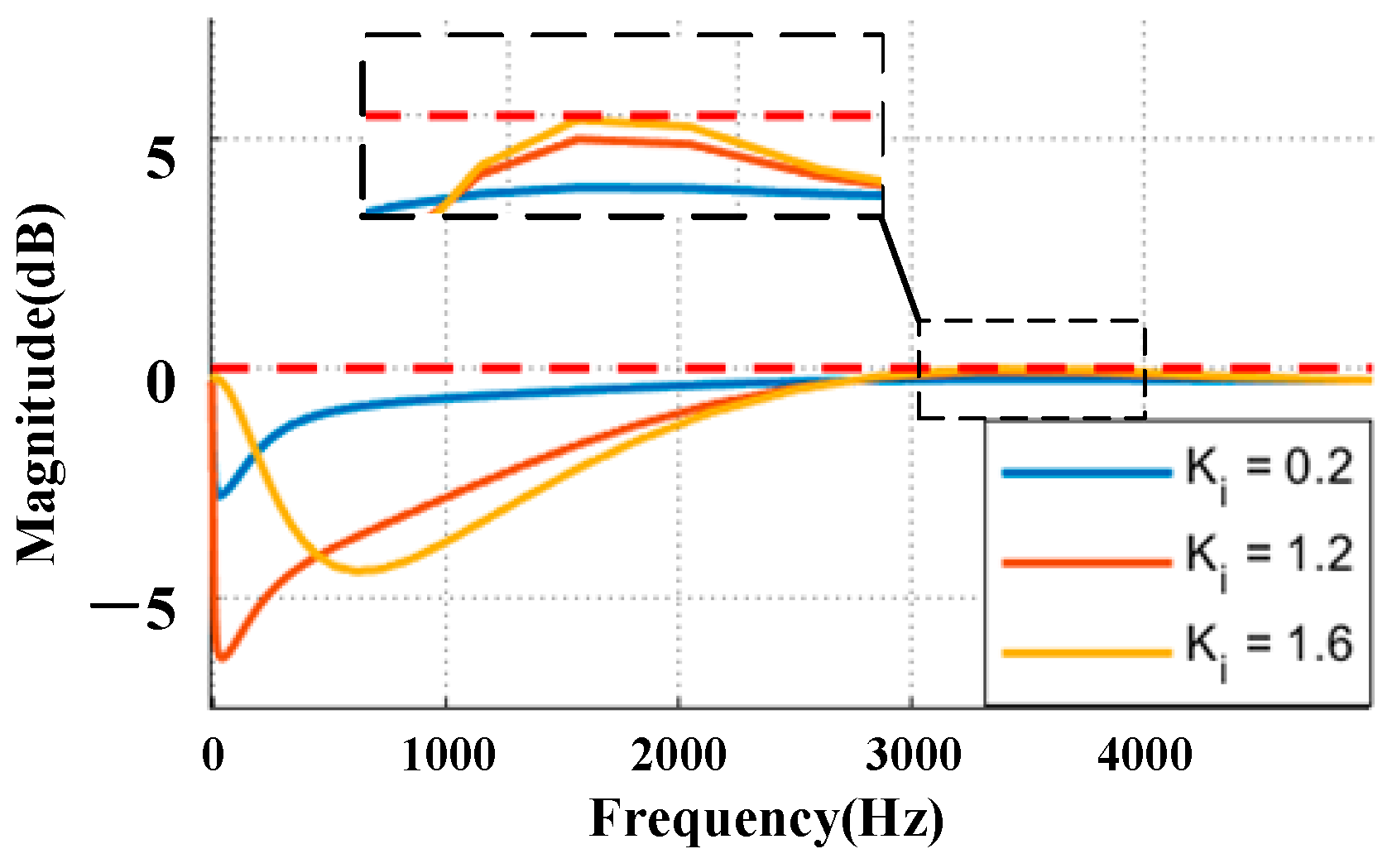
From Equation (13), it can be seen that to ensure the global stability of the motor control system, strict amplitude conditions must be met. Under the premise that all other parameters are determined, this criterion actually defines the theoretical stable boundary of the gain coefficient . By substituting the parameters of the motor in this paper, when the current loop bandwidth is 200 Hz, and , the theoretical upper limit of the gain for full-frequency band absolute stability is approximately 1.6198. Figure 5 shows the amplitude–frequency curve of , indicating that the smaller the , the higher the stability, and the larger the , the corresponding stability decreases.
Figure 5.
The amplitude–frequency curve of .
.
4. An Improved Repeated Control Method Based on Fuzzy Dynamic Gain Scheduling
Based on the stability analysis of the repeated controller in Section 3.3, it can be known that the forward-learning gain of the constructed controller needs to be within the theoretical stability boundary. The size of this gain directly affects the balance between the dynamic response speed of the system and the stability error: if the value is too large, the system’s suppression speed and accuracy for the target harmonic are higher, but it is prone to amplifying non-characteristic sub-harmonics, increasing the risk of system instability and divergence; conversely, if the value is too small, the system can maintain a higher steady-state robustness, but the error learning and integration process will become sluggish, resulting in a long steady-state convergence time and lower harmonic suppression accuracy. Currently, to balance the rapidity of harmonic suppression and the global stability of the system, the value of is often determined by trial and error. Simulation has found that in a stable system, a larger value of will lead to an increase in the content of the third harmonic on the d and q axes of the motor. Therefore, the fuzzy dynamic gain scheduling logic introduced in this paper can adaptively adjust this gain according to the real-time extracted harmonic size.
This paper uses a second-order infinite impulse response band-pass filter with a center frequency of to extract the third harmonic. Its difference equation in the discrete domain can be expressed as
where represents the system current tracking error; and are the discrete coefficients obtained after the band-pass filter undergoes the bilinear transformation.
Since the extracted harmonic components are high-frequency alternating oscillation signals, if they are directly used as the adjustment basis for the controller, it will cause the control variable to fluctuate violently. Therefore, in this paper, they are fully rectified, and a dual-cascaded first-order low-pass filter network is introduced to eliminate the double-frequency ripple caused by rectification and extract its smooth DC envelope amplitude :
where represents the envelope smoothing coefficient.
Then, the envelope components along the d-axis and q-axis are vectorially combined to obtain the comprehensive distortion characteristic value of this harmonic:
In the text, represents the overall comprehensive harmonic distortion characteristic value, and represents the comprehensive harmonic distortion characteristic value of the third harmonic.
To reduce the computing resources of the microprocessor, this paper adopts an analytical fuzzy penalty function to achieve dynamic adjustment of gain. The definition is as the maximum allowable gain of the system, and as the guaranteed steady-state gain. The scheduling logic consists of two adaptive factors:
- (1)
- Suppression demand factor: this assesses the severity of the current harmonic. When reaches the preset upper limit , this factor approaches 1, enabling the system to increase the gain:
- (2)
- Stable penalty factor: When approaches the upper limit , this factor rapidly decays to 0, causing the system to reduce its gain.
In this paper, is set to
, while
is 1.5 times the amplitude of the third harmonic on the
axes obtained when only PI control is employed.
Then, the target gain of the controller is
Under dynamic operating conditions (such as sudden changes in load), the target gain may undergo a step change. If it is directly applied to the feedback channel of the repetitive controller, the high-frequency sudden change instructions may cause current oscillations. Therefore, before the controller is discretized and updated, this paper inserts a first-order inertial link for processing:
where represents the damping smoothing coefficient.
5. Simulation Verification
To verify the effectiveness of the proposed control method, a simulation model was built in the Matlab R2021b/Simulink environment. The core simulation parameters are shown in Table 1. By comparing the current waveforms and harmonic characteristics of the “no repetitive controller”, “repetitive controller with ”, “repetitive controller with ”, and “repetitive controller with adaptive ” schemes under the conditions of 750 r/min with a load of 90 N, 1500 r/min with a load of 90 N, and 1500 r/min with a load of 45 N, the performance improvement effect of the proposed method was analyzed.
Table 1.
System parameters.
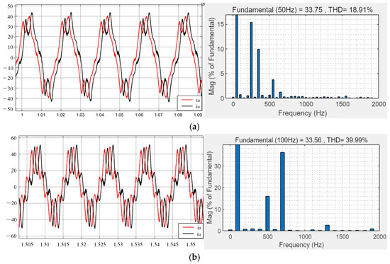
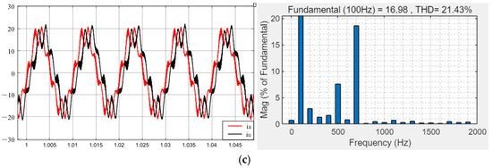
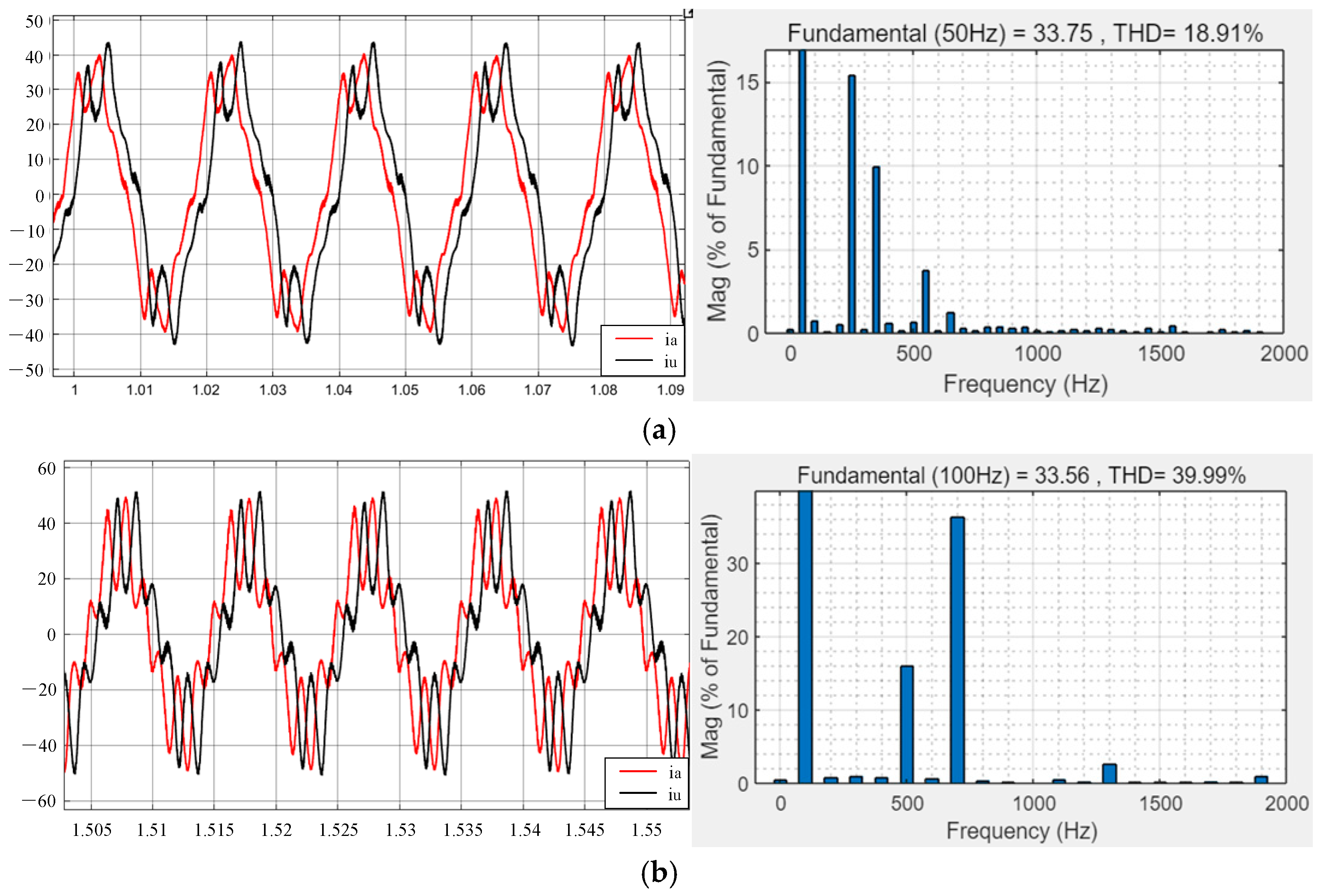
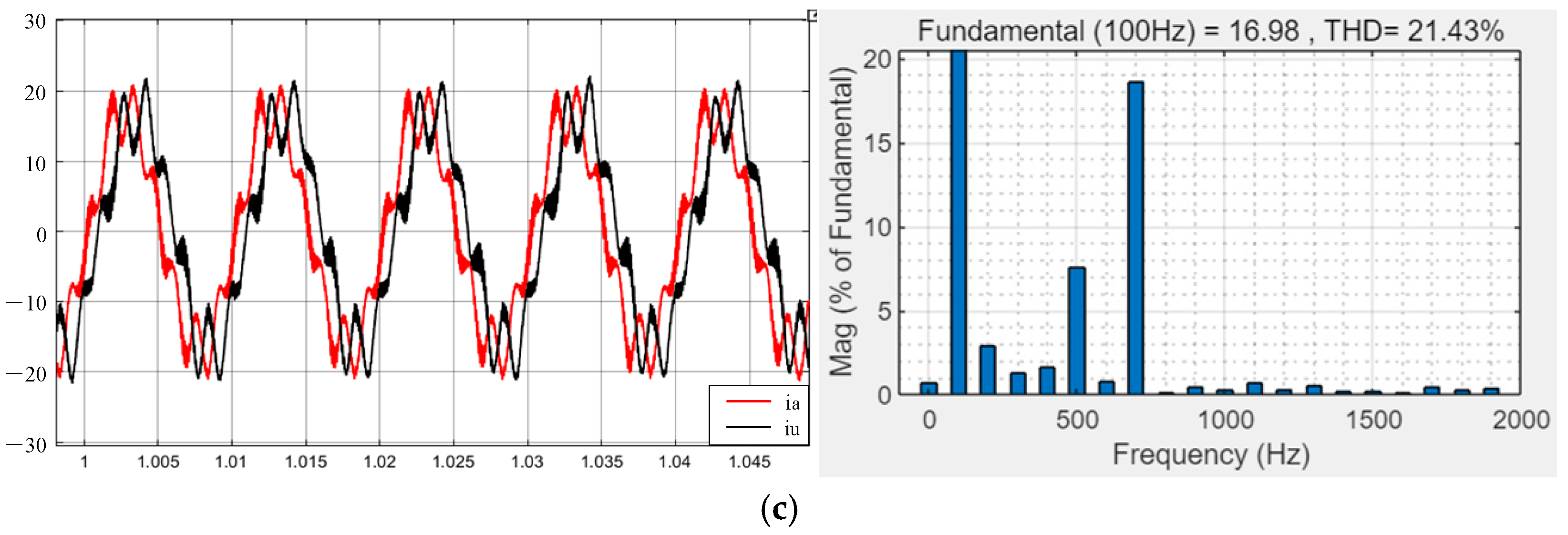
Figure 6 shows the current waveform and harmonic spectrum without repetitive control. The current waveform is severely distorted. The specific data are as follows:
Figure 6.
The current loop only uses the current waveform with PI control and FFT analysis. (a) The motor operates at 750 r/min with a load of 90 N. (b) The motor operates at 1500 r/min with a load of 90 N. (c) The motor operates at 1500 r/min with a load of 45 N.
When the motor is running at 750 rpm with a load of 90N, the THD is approximately 18.91%, with the 5th harmonic accounting for about 15.4%, the 7th harmonic about 9.99%, the 11th harmonic about 3.76%, the 13th harmonic about 1.28%, the 17th harmonic about 0.42%, the 19th harmonic about 0.43%, and the 2nd and 4th harmonics accounting for approximately 0.77% and 0.52% respectively.
When the motor is running at 1500 rpm with a load of 90 N, the THD is approximately 39.99%, with the 5th harmonic accounting for about 16.08%, the 7th harmonic about 36.31%, the 11th harmonic about 0.61%, the 13th harmonic about 2.7%, the 17th harmonic about 0.3%, the 19th harmonic about 1.06%, and the 2nd and 4th harmonics accounting for approximately 0.88% and 0.87% respectively.
When the motor is running at 1500 rpm with a load of 45N, the THD is approximately 21.43%, with the 5th harmonic accounting for about 7.58%, the 7th harmonic about 18.65%, the 11th harmonic about 0.71%, the 13th harmonic about 0.58%, the 17th harmonic about 0.49%, the 19th harmonic about 0.42%, and the 2nd and 4th harmonics accounting for approximately 2.88% and 1.62% respectively.
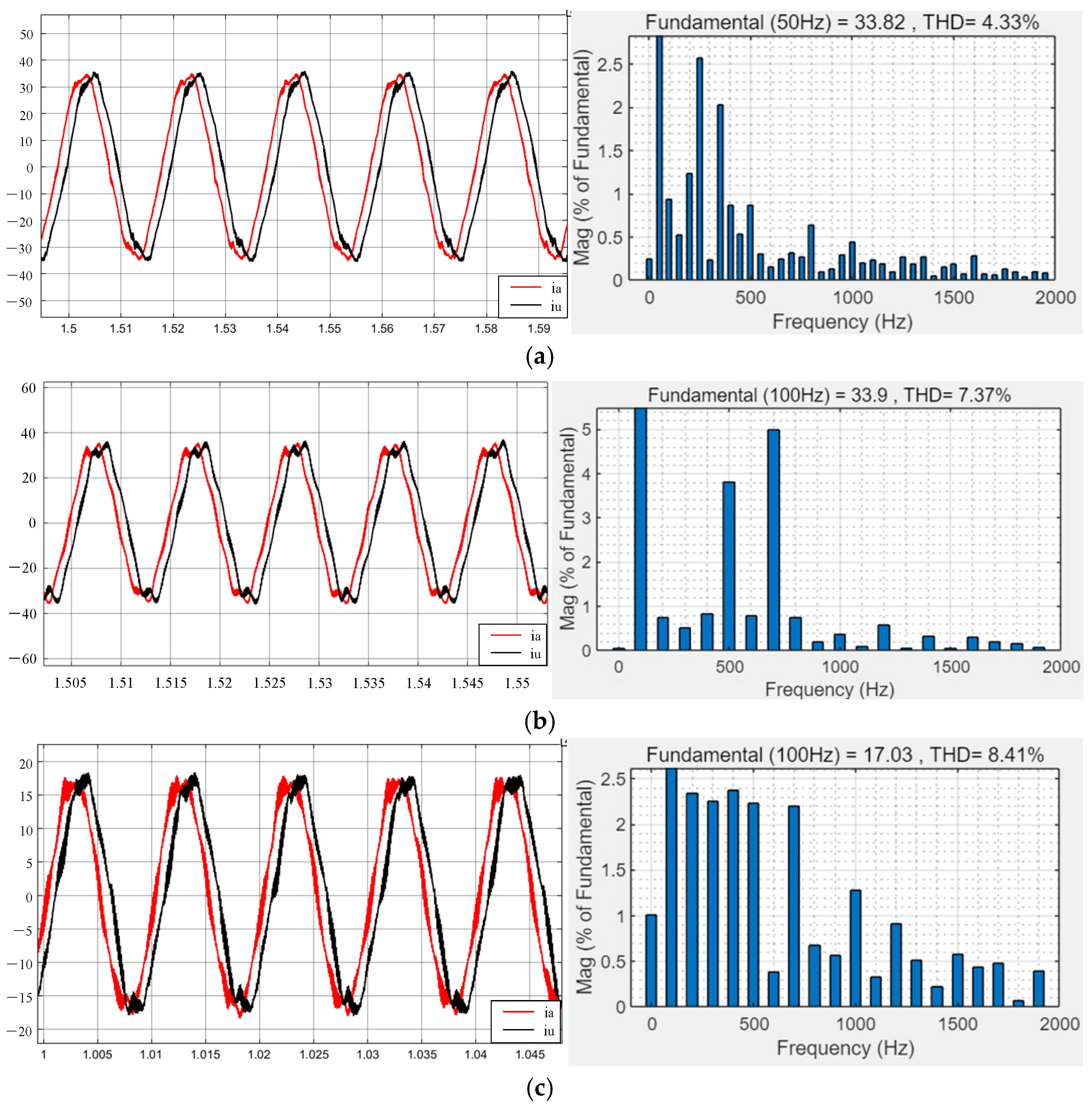
Figure 7 shows the current waveform and harmonic spectrum when . At this point, the harmonic analysis of the motors under various conditions is as follows:
Figure 7.
When the current loop adopts PI control and is in parallel with repetitive controller with , the current waveform and FFT analysis are presented. (a) The motor operates at 750 r/min with a load of 90 N. (b) The motor operates at 1500 r/min with a load of 90 N. (c) The motor operates at 1500 r/min with a load of 45 N.
When the motor rotates at 750 rpm with a load of 90 N, the current THD is approximately 4.33%, with the 5th harmonic accounting for about 2.57%, the 7th harmonic about 2.04%, the 11th harmonic about 0.31%, the 13th harmonic about 0.25%, the 17th harmonic about 0.1%, the 19th harmonic about 0.29%, the 2nd harmonic about 0.94%, and the 4th harmonic about 1.24%.
When the motor rotates at 1500 rpm with a load of 90 N, the current THD is approximately 7.37%, with the 5th harmonic accounting for about 3.82%, the 7th harmonic about 4.99%, the 11th harmonic about 0.1%, the 13th harmonic about 0.06%, the 17th harmonic about 0.19%, the 19th harmonic about 0.08%, the 2nd harmonic about 0.74%, and the 4th harmonic about 0.83%.
When the motor rotates at 1500 rpm with a load of 45 N, the current THD is approximately 8.41%, with the 5th harmonic accounting for about 2.57%, the 7th harmonic about 2.04%, the 11th harmonic about 0.31%, the 13th harmonic about 0.25%, the 17th harmonic about 0.1%, the 19th harmonic about 0.29%, the 2nd harmonic about 0.94%, and the 4th harmonic about 1.24%.
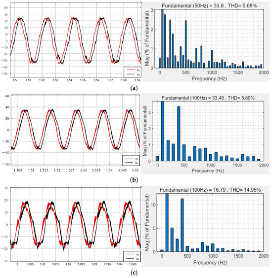
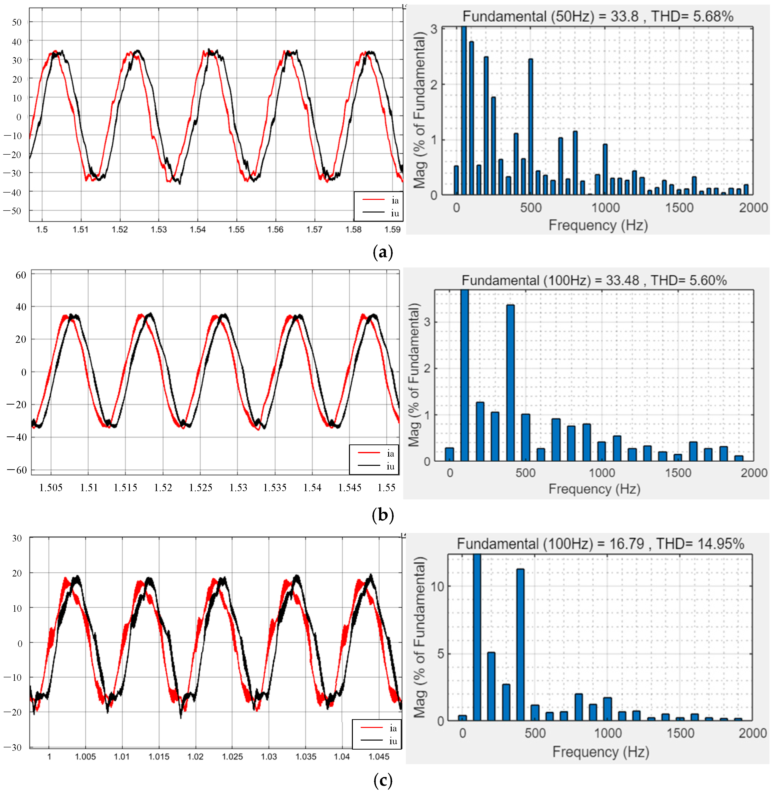
Figure 8 shows the current waveform and harmonic spectrum when . At this point, the harmonic analysis of the motors under various conditions is as follows:
Figure 8.
When the current loop adopts PI control and is in parallel with repetitive controller with , the current waveform and FFT analysis are presented. (a) The motor operates at 750 r/min with a load of 90 N. (b) The motor operates at 1500 r/min with a load of 90 N. (c) The motor operates at 1500 r/min with a load of 45 N.
When the motor rotates at 750 rpm with a load of 90 N, the current THD is approximately 5.68%, with the 5th harmonic accounting for about 1.77%, the 7th harmonic about 0.34%, the 11th harmonic about 0.44%, the 13th harmonic about 0.27%, the 17th harmonic about 0.26%, the 19th harmonic about 0.37%, and the non-characteristic sub-harmonics increase, with the 2nd harmonic accounting for about 2.77% and the 4th harmonic about 2.5%.
When the motor rotates at 1500 rpm with a load of 90 N, the current THD is approximately 5.6%, with the 5th harmonic accounting for about 1.01%, the 7th harmonic about 0.92%, the 11th harmonic about 0.55%, the 13th harmonic about 0.33%, the 17th harmonic about 0.28%, the 19th harmonic about 0.12%, and the non-characteristic sub-harmonics increase, with the 2nd harmonic accounting for about 1.28% and the 4th harmonic about 3.36%.
When the motor rotates at 1500 rpm with a load of 45 N, the current THD is approximately 14.95%, with the 5th harmonic accounting for about 1.17%, the 7th harmonic about 0.7%, the 11th harmonic about 0.69%, the 13th harmonic about 0.22%, the 17th harmonic about 0.22%, the 19th harmonic about 0.18%, and the non-characteristic sub-harmonics increase, with the 2nd harmonic accounting for about 5.08% and the 4th harmonic about 11.26%.
The results indicate that the fixed gain repetitive control has limitations: if the gain is too small, the harmonic suppression capability is insufficient; if the gain is too large, although the effect of suppressing characteristic harmonics is better, it is prone to increasing non-characteristic sub-harmonics, threatening the stability of the system.
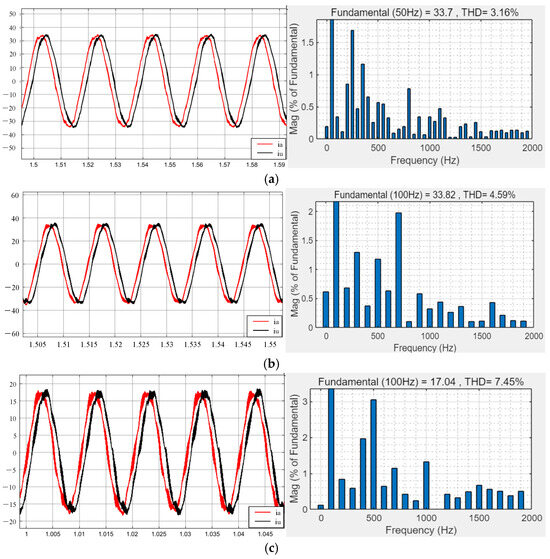
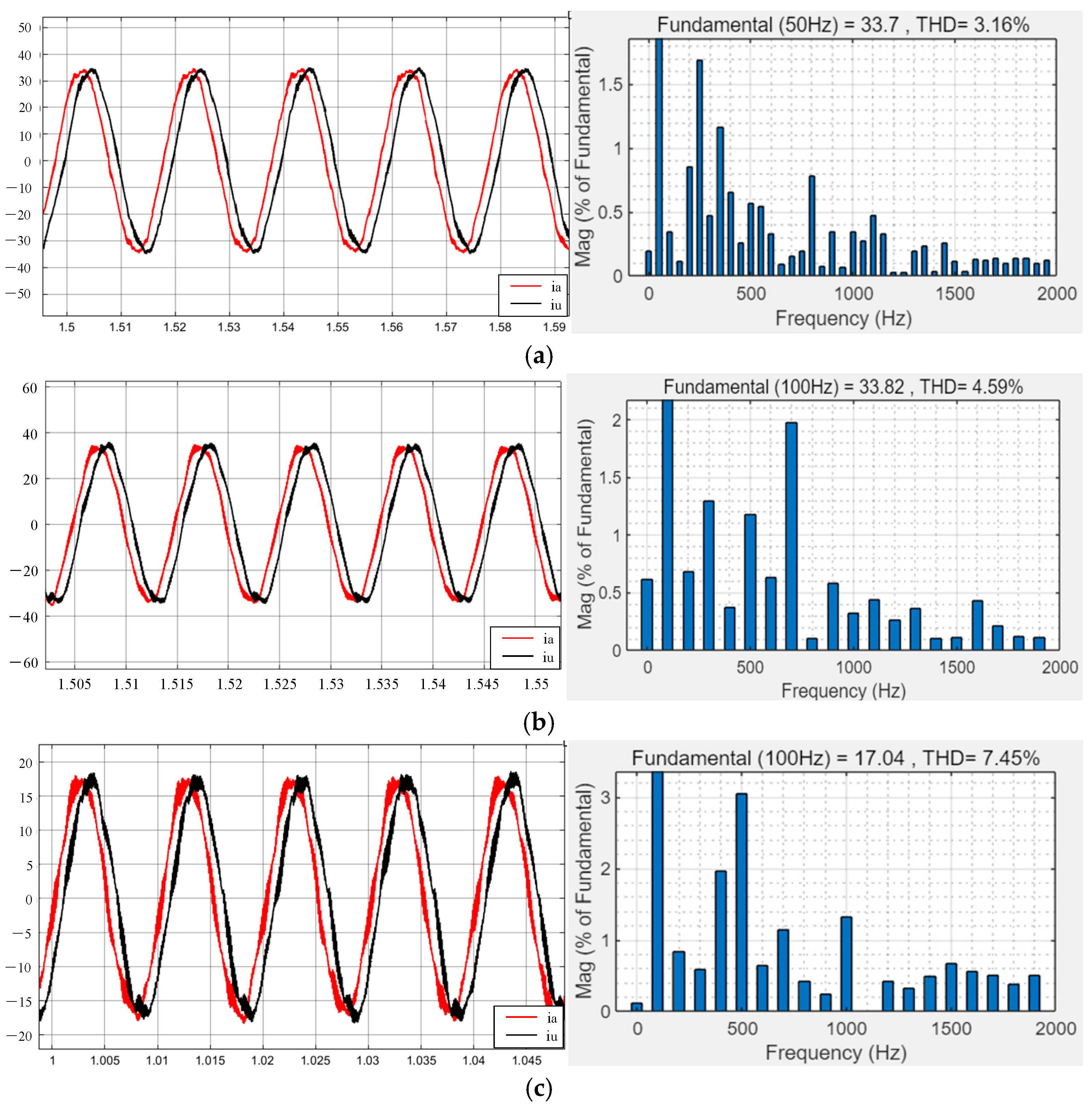
Figure 9 shows the repetitive control current waveform and harmonic spectrum when using the fuzzy adaptive method. The harmonic content under each operating condition is as follows:
Figure 9.
When the current loop adopts PI control and the parallel uses the repetitive controller method based on fuzzy adaptive algorithm, the current waveform and FFT analysis are conducted. (a) The motor operates at 750 r/min with a load of 90 N. (b) The motor operates at 1500 r/min with a load of 90 N. (c) The motor operates at 1500 r/min with a load of 45 N.
When the motor is running at 750 rpm with a load of 90 N, the total harmonic distortion (THD) is approximately 3.16%, among which the 5th harmonic accounts for about 1.69%, the 7th harmonic about 1.17%, the 11th harmonic about 0.55%, the 13th harmonic about 0.09%, the 17th harmonic about 0.07%, the 19th harmonic about 0.07%, the 2nd harmonic about 0.34%, and the 4th harmonic about 0.86%.
When the motor is running at 1500 rpm with a load of 90 N, the total harmonic distortion (THD) is approximately 4.59%, among which the 5th harmonic accounts for about 1.18%, the 7th harmonic about 1.98%, the 11th harmonic about 0.44%, the 13th harmonic about 0.36%, the 17th harmonic about 0.21%, the 19th harmonic about 0.11%, the 2nd harmonic about 0.68%, and the 4th harmonic about 0.38%.
The results prove that the proposed method has a superior suppression effect on the fifth and seventh harmonics, and effectively avoids the problem of non-characteristic harmonic amplification caused by a fixed high gain, verifying the effectiveness of the proposed method.
When the motor is running at 1500 rpm with a load of 45 N, the total harmonic distortion (THD) is approximately 7.45%, among which the 5th harmonic accounts for about 3.06%, the 7th harmonic about 1.15%, the 13th harmonic about 0.32%, the 17th harmonic about 0.52%, the 19th harmonic about 0.53%, the 2nd harmonic about 0.3%, and the 4th harmonic about 1.23%.
6. Conclusions
To address the current distortion of the current caused by the fifth and seventh characteristic harmonics during the operation of the dual three-phase permanent magnet synchronous motor, as well as the deficiency of the traditional repetitive control with fixed gain in being unable to balance the dynamic response speed and system stability, this paper designs an improved repetitive control strategy based on fuzzy dynamic gain scheduling. Through the specific harmonic feature extraction module, the comprehensive distortion characteristic values of the target harmonic and the warning harmonic are obtained in real time, and a fuzzy scheduling logic composed of the suppression demand factor and the stability penalty factor is constructed to achieve the dynamic adjustment of the forward-learning gain in repetitive control. Finally, the effectiveness of the proposed strategy is verified through simulation.
Author Contributions
This research article contains the authors’ contributions to the writing and completion of such an academic achievement project. The authors Y.N. and P.Z. mainly completed the physical model design, data analysis and writing of the article. The authors B.L. and S.L. mainly performed literature retrieval, the literature summary and literature analysis. All authors have read and agreed to the published version of the manuscript.
Funding
This research received no external funding.
Data Availability Statement
The datasets used and analyzed during the current study are available from the corresponding author on reasonable request.
Acknowledgments
During the process of writing this thesis, I received a lot of support and assistance. I would like to express my gratitude to my supervisor Peng Zhu. From the topic selection and conception, to the framework construction and final revision, he has always provided me with meticulous guidance and valuable support. Your rigorous academic attitude and profound professional knowledge have enabled me to achieve a higher level in my work.
Conflicts of Interest
The authors declare no conflicts of interest.
References
- Abdelwanis, M.I.; Hegab, A.; Albatati, F.; El-Sehiemy, R.A. Adaptive Speed Tuning of Permanent Magnet Synchronous Motors Using Intelligent Fuzzy Based Controllers for Pumping Applications. Processes 2025, 13, 1393. [Google Scholar] [CrossRef] [Scilit]
- König, P.; Sharma, D.; Konda, K.R.; Xie, T.; Höschler, K. Comprehensive Review on Cooling of Permanent Magnet Synchronous Motors and Their Qualitative Assessment for Aerospace Applications. Energies 2023, 16, 7524. [Google Scholar] [CrossRef] [Scilit]
- Luu, P.T.; Lee, J.-Y.; Lee, J.-H.; Park, J.-W. Electromagnetic and Thermal Analysis of Permanent-Magnet Synchronous Motors for Cooperative Robot Applications. IEEE Trans. Magn. 2020, 56, 7512804. [Google Scholar] [CrossRef] [Scilit]
- Satake, A.; Okamoto, Y.; Kato, S. Design of Coupling Cancellation Control for a Double-winding PMSM. IEEE J. Ind. Appl. 2017, 6, 29–35. [Google Scholar] [CrossRef] [Scilit]
- Fang, H.; Li, D.; Qu, R.; Yan, P. Modulation effect of slotted structure on vibration response in electrical machines. IEEE Trans. Ind. Electron. 2019, 66, 2998–3007. [Google Scholar] [CrossRef] [Scilit]
- Li, W.; Song, P.; Li, Q.; Li, Z.; Kar, N.C. Open-phase fault modeling for dual three-phase PMSM using vector space decomposition and negative sequence components. IEEE Trans. Magn. 2022, 58, 1–6. [Google Scholar] [CrossRef] [Scilit]
- Diab, A.M.; Bozhko, S.; Galea, M.; Gerada, C. Stable and robust design of active disturbance-rejection current controller for permanent magnet machines in transportation systems. IEEE Trans. Transp. Electrif. 2020, 6, 1421–1433. [Google Scholar] [CrossRef] [Scilit]
- Yan, L.; Zhu, Z.Q.; Qi, J.; Ren, Y.; Gan, C.; Brockway, S.; Hilton, C. Multiple synchronous reference frame current harmonic regulation of dual three phase PMSM with enhanced dynamic performance and system stability. IEEE Trans. Ind. Electron. 2022, 69, 8825–8838. [Google Scholar] [CrossRef] [Scilit]
- Su, J.; Zhang, J.; An, Q. Complex Vector PI Controller Based Current Harmonics Suppression of PMSM Drives. Electr. Mach. Control Appl. 2021, 48, 30–36. [Google Scholar]
- Tian, M.; Wang, B.; Yu, Y.; Dong, Q.; Xu, D. Adaptive Active Disturbance Rejection Control for Uncertain Current Ripples Suppression of PMSM Drives. IEEE Trans. Ind. Electron. 2024, 71, 2320–2331. [Google Scholar] [CrossRef] [Scilit]
- Zhang, Q.; Guo, H.; Guo, C.; Liu, Y.; Wang, D.; Lu, K.; Chen, D. An adaptive proportional-integral-resonant controller for speed ripple suppression of PMSM drive due to current measurement error. Int. J. Electr. Power Energy Syst. 2021, 129, 106866. [Google Scholar] [CrossRef] [Scilit]
- Shin, L.; Lee, S.; Cho, Y. Harmonic current control for dual three-phase PMSM using average periodic delay-based repetitive controller. J. Power Electron. 2025, 25, 1698–1708. [Google Scholar] [CrossRef] [Scilit]
- Wu, Y.; Song, X.; Li, H.; Chen, B. Suppression of Harmonic Current in Permanent Magnet Synchronous Motors Using Improved Repetitive Controller. Diangong Jishu Xuebao/Trans. China Electrotech. Soc. 2019, 34, 2277–2286. [Google Scholar] [CrossRef] [Scilit]
- Zhu, Y.; Zhu, L.; Xiao, M.; Meng, L. Repetitive Controller Based on Geometric Constraint Optimization and Its Application to Current Harmonic Suppression of PMSM. Diangong Jishu Xuebao/Trans. China Electrotech. Soc. 2024, 39, 1059–1073. [Google Scholar]
- Cao, Z.; Feng, Y.; Yu, X.; Khan, R.F.A. Discrete-Time Sliding Mode Repetitive Control for Servo Motor Systems. IEEE/ASME Trans. Mechatron. 2025, 30, 5444–5455. [Google Scholar] [CrossRef] [Scilit]
- Tian, M.; Wang, B.; Yu, Y.; Dong, Q.; Xu, D. Discrete-Time Repetitive Control-Based ADRC for Current Loop Disturbances Suppression of PMSM Drives. IEEE Trans. Ind. Inform. 2022, 18, 3138–3149. [Google Scholar] [CrossRef] [Scilit]
- Yan, Y.; He, X.; Wu, L.; Yu, Q. Adaptive event-triggered control for a family of uncertain switched nonlinear systems with full-state constraints. Inf. Sci. 2023, 624, 512–528. [Google Scholar] [CrossRef] [Scilit]
- Hu, Z.; Ma, R. Adaptive event-triggered tracking control via switching functions. Automatica 2026, 185, 112813. [Google Scholar] [CrossRef] [Scilit]
- Chang, X.-H.; Han, X. Observer-Based Fuzzy l2-l∞ Control for Discrete-Time Nonlinear Systems. IEEE Trans. Fuzzy Syst. 2024, 32, 2523–2528. [Google Scholar] [CrossRef] [Scilit]
- Hu, Z.; Liu, S.; Luo, W.; Wu, L. Resilient Distributed Fuzzy Load Frequency Regulation for Power Systems Under Cross-Layer Random Denial-of-Service Attacks. IEEE Trans. Cybern. 2022, 52, 2396–2406. [Google Scholar] [CrossRef] [Scilit] [PubMed]

Disclaimer/Publisher’s Note: The statements, opinions and data contained in all publications are solely those of the individual author(s) and contributor(s) and not of MDPI and/or the editor(s). MDPI and/or the editor(s) disclaim responsibility for any injury to people or property resulting from any ideas, methods, instructions or products referred to in the content. |
© 2026 by the authors. Licensee MDPI, Basel, Switzerland. This article is an open access article distributed under the terms and conditions of the Creative Commons Attribution (CC BY) license.