


Abstract
To meet the stringent requirements of broadband operations, high stability and low dispersion in high-power microwave systems, this paper proposes a broadband linearly polarized quasi-non-diffractive wave generation method based on a filter-equivalent circuit model. A metasurface structure centered at 75 GHz is designed for this method, which enables the generation of linearly polarized quasi-non-diffractive beams in the 60–90 GHz band with a 40% relative bandwidth and a maximum non-diffractive distance of 120 mm. By optimizing the metasurface’s phase response through the equivalent circuit model, the proposed method effectively suppresses the dispersion effects that limit bandwidth utilization in existing designs. Simulation results confirm that the generated beams maintain excellent stability across the entire operating band, with minimal variations in the maximum non-diffractive distance. This work fills the research gap in broadband achromatic linearly polarized quasi-non-diffractive beams, and its relative bandwidth outperforms all previous linear polarization designs. It thus provides a reliable technical solution for long-distance, high-efficiency electromagnetic wave transmission in defense, industrial and medical applications that rely on high-power microwave technology.
1. Introduction
With the rapid development of high-power microwave technology in defense, industry, and medical fields, greater requirements have been imposed on the long-distance and high-stability transmission of electromagnetic wave beams. Effectively avoiding diffraction while breaking the limitation of traditional focusing distances to achieve efficient long-range electromagnetic wave transmission is critically significant for these applications. To address these demands, non-diffraction beams [1] have been extensively studied, including Bessel beams [2,3,4], Airy beams [5,6,7], Mathieu beams [8], and others. Within specific propagation distances, these beams exhibit stable wavefronts and power density distributions, thereby mitigating electromagnetic energy attenuation. Consequently, investigating generation methods for non-diffraction electromagnetic waves holds substantial importance.
Traditional beam generation techniques based on parabolic antennas or focused systems are limited by diffraction, resulting in a narrow depth of field (i.e., the beam expands quickly after the focal point). This makes them unsuitable for applications requiring a consistent intensity over extended distances (long depth of field) in high-power scenarios, despite their broadband capabilities. Recently, metasurfaces [9,10] have emerged as a pivotal research direction due to their exceptional electromagnetic manipulation capabilities. Generating non-diffraction beams via metasurfaces [11,12,13] has become a prominent application focus. In 2020, Huang et al. [7] successfully generated Airy beams at 5.86 GHz. In 2021, He et al. [14] utilized dielectric metasurfaces to realize the simultaneous control of linearly polarized zeroth-order Bessel beams, orbital angular momentum, and beam deflection at 140 GHz. In 2022, Huang et al. [15] achieved the arbitrary modulation of zeroth-order Bessel beams and orbital angular momentum at 0.161 THz. In 2023, Li et al. [6] demonstrated the generation of linearly polarized Airy beams at 0.8 THz and circularly polarized vortex beams at 1.3 THz.
However, existing metasurfaces face challenges in broadband and high-power applications. (1) Dispersion effects: Frequency variations induce significant fluctuations in the non-diffraction distance of generated beams, limiting bandwidth utilization. The deliberately chromatic metasurfaces have also found novel applications, such as in computational imaging and 3D depth sensing [16,17]. This highlights the versatility of engineered dispersion. The present work focuses on the former challenge—suppressing dispersion to achieve stable beam properties over a wide bandwidth—which is critical for directed energy and communication links. (2) Power handling capacity: High-frequency metasurfaces are prone to performance degradation due to dielectric loss and thermal effects. Achieving stable maximum non-diffraction distances within a specific bandwidth requires effective achromatic metasurface design. In 2017, Wang et al. [18] proposed a dispersion elimination method by simultaneously controlling the resonant phase and geometric phase, successfully realizing a broadband achromatic performance. However, this approach is only applicable to circularly polarized electromagnetic waves. Leveraging this theory, Zhang et al. [19] employed dielectric metasurfaces to generate Airy beams with nearly invariant maximum non-diffraction distances across 0.4–0.8 THz, achieving a fractional bandwidth of 66.6%. Chen et al. [20] demonstrated achromatic focusing and imaging using dielectric metasurfaces in the 470–670 nm wavelength range. Nevertheless, few studies have reported broadband achromatic linearly polarized quasi-non-diffraction beams. In 2016, Zhong et al. [21] generated linearly polarized quasi-non-diffraction beams at 28.5 GHz using ideal phase-compensated dispersion units, attaining a relative bandwidth of 14%. In 2017, Zhong et al. [22] further achieved off-axis linearly polarized quasi-non-diffraction beams at 29 GHz with a fractional bandwidth of 13.8%. Significant challenges remain in realizing broadband linearly polarized achromatic quasi-non-diffraction beams at high-frequency bands.
This paper proposes a method utilizing a filter-based equivalent circuit model to design broadband linearly polarized achromatic metasurfaces. Based on this model, a metasurface is designed, operating from 60 GHz to 90 GHz with a relative bandwidth of 40%. Within this frequency range, the metasurface generates linearly polarized quasi-non-diffraction beams while maintaining stable maximum non-diffraction distances. Fundamentally, prior LP achromatic quasi-non-diffractive designs primarily relied on propagation phase manipulation using dielectric pillars or similar resonant elements, which inherently limits the bandwidth due to dispersion. In contrast, this work introduces a filter-based equivalent circuit model as the core design strategy. This approach allows for the direct synthesis and control of the phase response and its frequency derivative (group delay), enabling proactive dispersion compensation over a predetermined bandwidth. This model-driven methodology represents a distinct and more general design paradigm compared to the element tuning approaches commonly used previously.
The remainder of this paper is organized as follows. Section 2 details the design of the broadband linearly polarized achromatic metasurface, including the equivalent circuit analysis and the physical realization of the meta-atoms. Section 3 presents the simulation results and performance analysis of the proposed metasurface, along with comparisons to previous works. Finally, Section 4 concludes this paper.
2. Design of Broadband Linearly Polarized Achromatic Metasurface
2.1. Equivalent Circuit Analysis
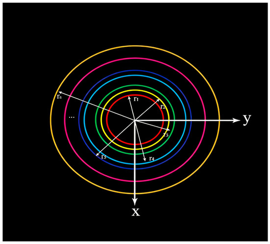
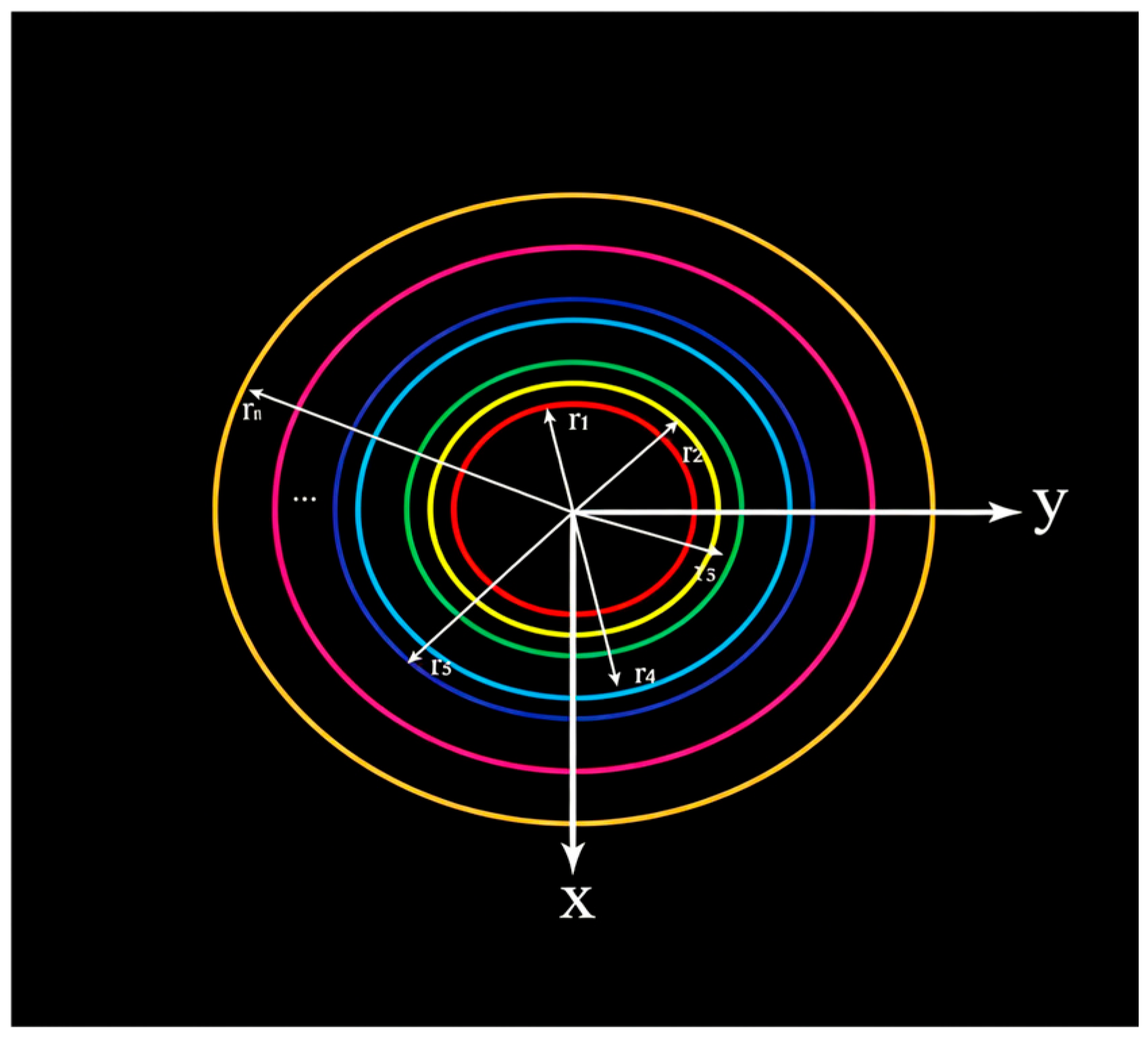
As illustrated in Figure 1, the array aperture is divided into N concentric annular regions, with identical meta-atoms within each region. For a reflectarray under a normal incidence, the required phase distribution to generate a zeroth-order Bessel beam must satisfy the following formula:
where is the frequency of the beam in free space, is the speed of light in free space, and denotes the Cartesian coordinates of each region. While Equation (1) is given for the normal incidence, the following synthesis method based on the equivalent circuit model can be generalized to an offset feed configuration by incorporating the appropriate linear phase gradient in the target phase function. To generate broadband achromatic quasi-non-diffraction beams based on the equivalent circuit method, the phase distribution of each region must be adjusted. Taking Region 1 as the reference, the relative phase of each region can be expressed as
Figure 1.
Region division of the array aperture, where r denotes the radius of the concentric annular regions. (Different color-lines represent the boundaries of different regions).
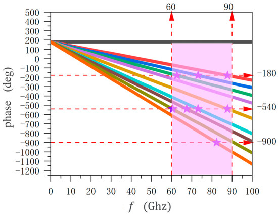
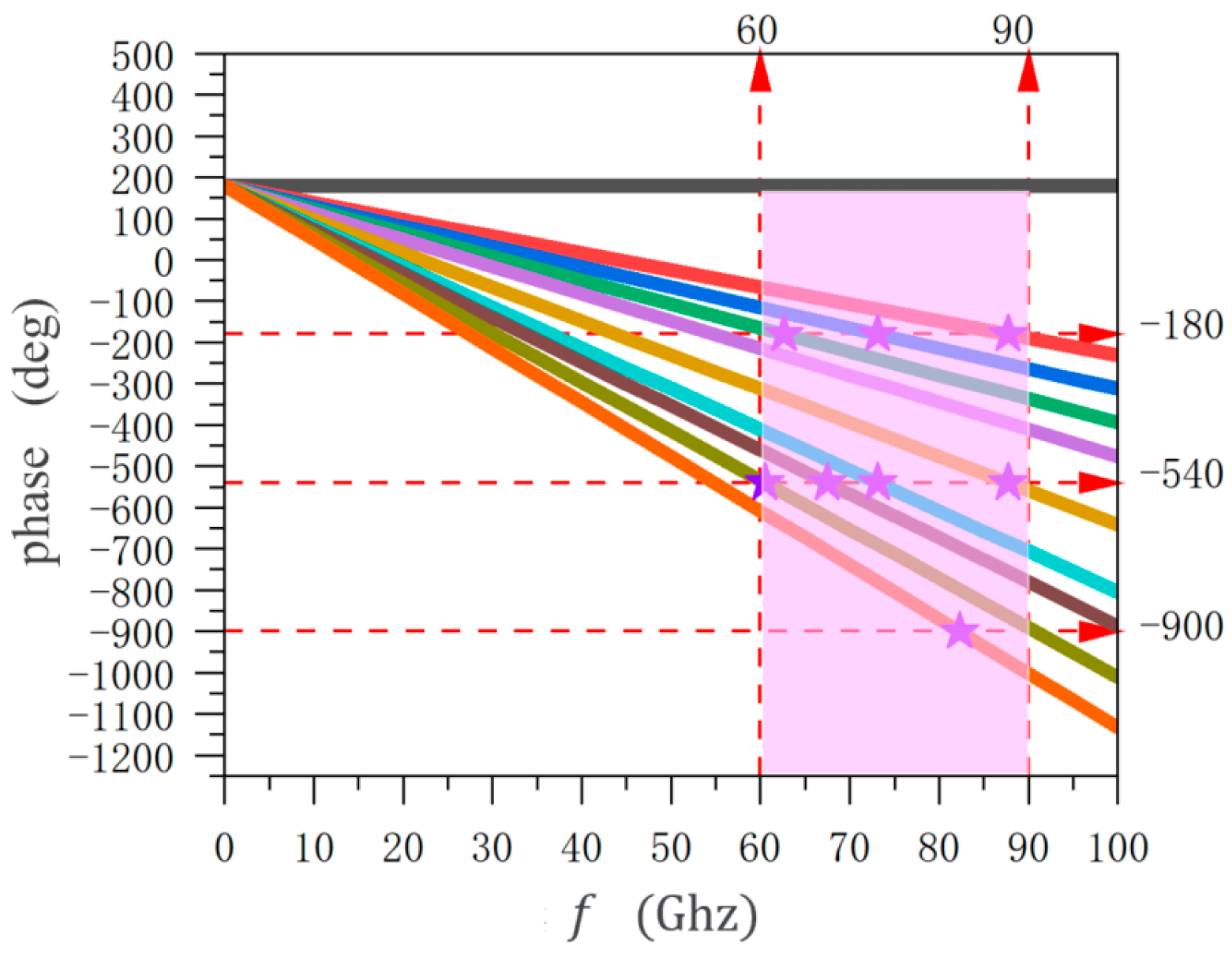
Here, the first region is a pure metallic structure. Figure 2 illustrates the frequency-dependent reflection coefficient phase of each metasurface region within the E-band. Since the central metallic region is selected as the phase reference, the resonant frequency in this work is defined as the frequency at which the phase reaches . Elements with lying within the operational bandwidth are termed resonant components, while those with outside the bandwidth are classified as non-resonant components. In Figure 2, only the meta-atoms in Region 1 exhibit resonant behavior. To ensure the resonance of meta-atoms within or near the operational bandwidth, the phase distribution formula requires an adjustment, as follows:
where is an integer, thus having no impact on the phase distribution across the regions. Table 1 lists the resonant frequencies, , , and , of meta-atoms in distinct regions, corresponding to phase values of , , and , respectively. The highlighted resonant frequencies in Table 1 are ultimately employed in the precise design of the reflective elements.
Figure 2.
Frequency-dependent ideal reflection phase of different regions in the reflectarray. The curves represent the phase-frequency variation curves of the unit cells in their respective regions. The black curve corresponds to Region 1, the red curve to Region 2, the blue curve to Region 3, the green curve to Region 4, the purple curve to Region 5, the brown curve to Region 6, the sky blue curve to Region 7, the dark brown curve to Region 8, the gold curve to Region9, and the orange curve to Region 10. The star symbols indicate the intersection points of these curves with the phase lines of −180°, −540°, and −900°.
Table 1.
Corresponding resonant frequencies of different regions in the reflectarray antenna.
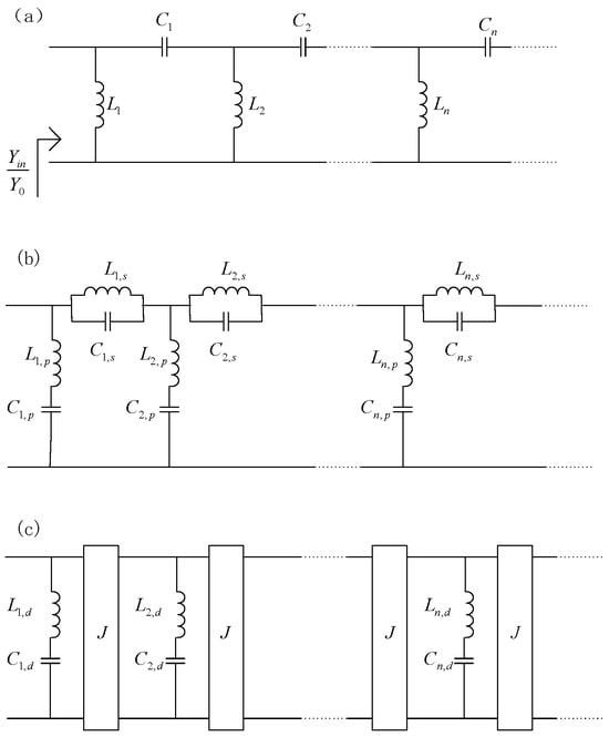
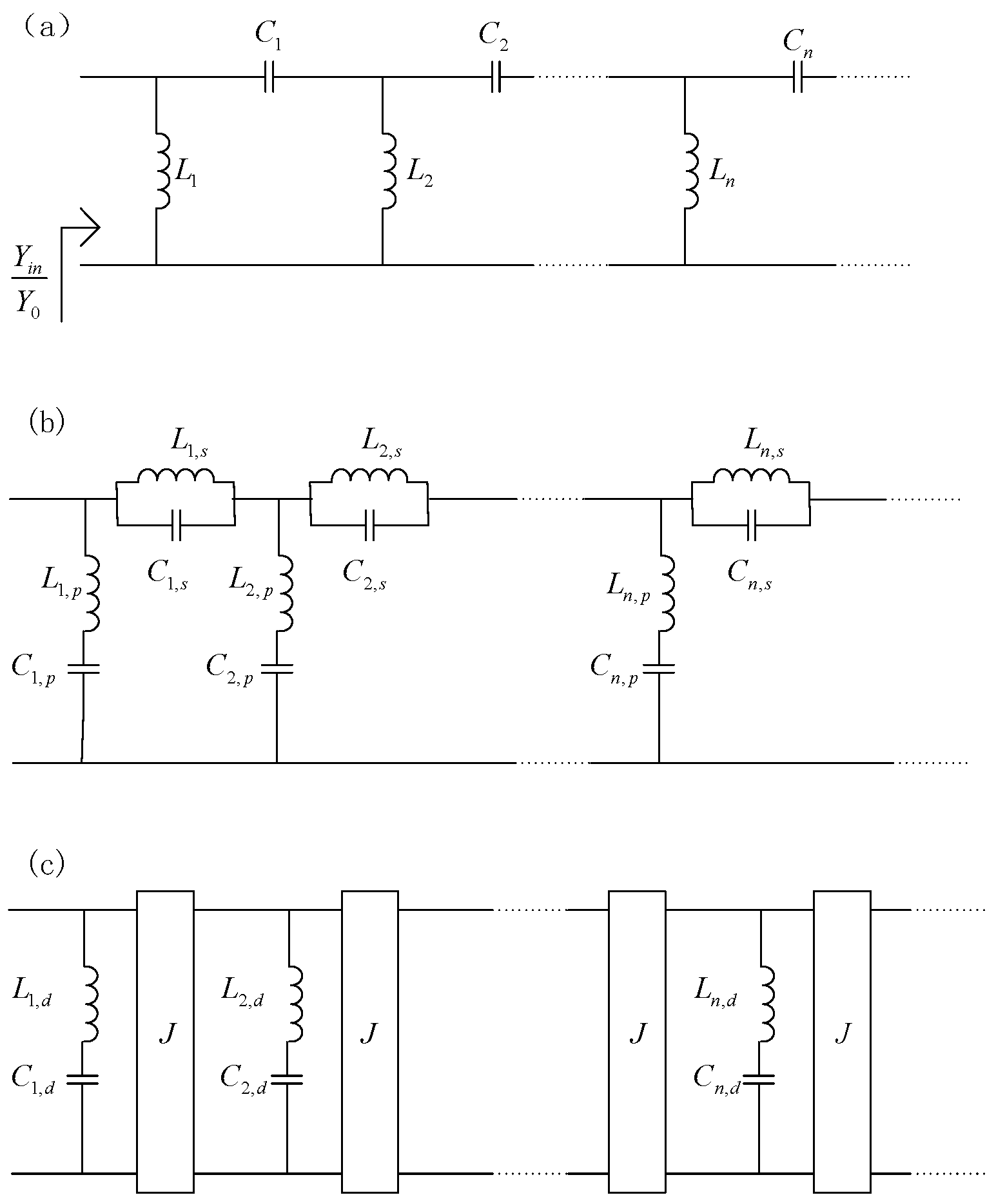
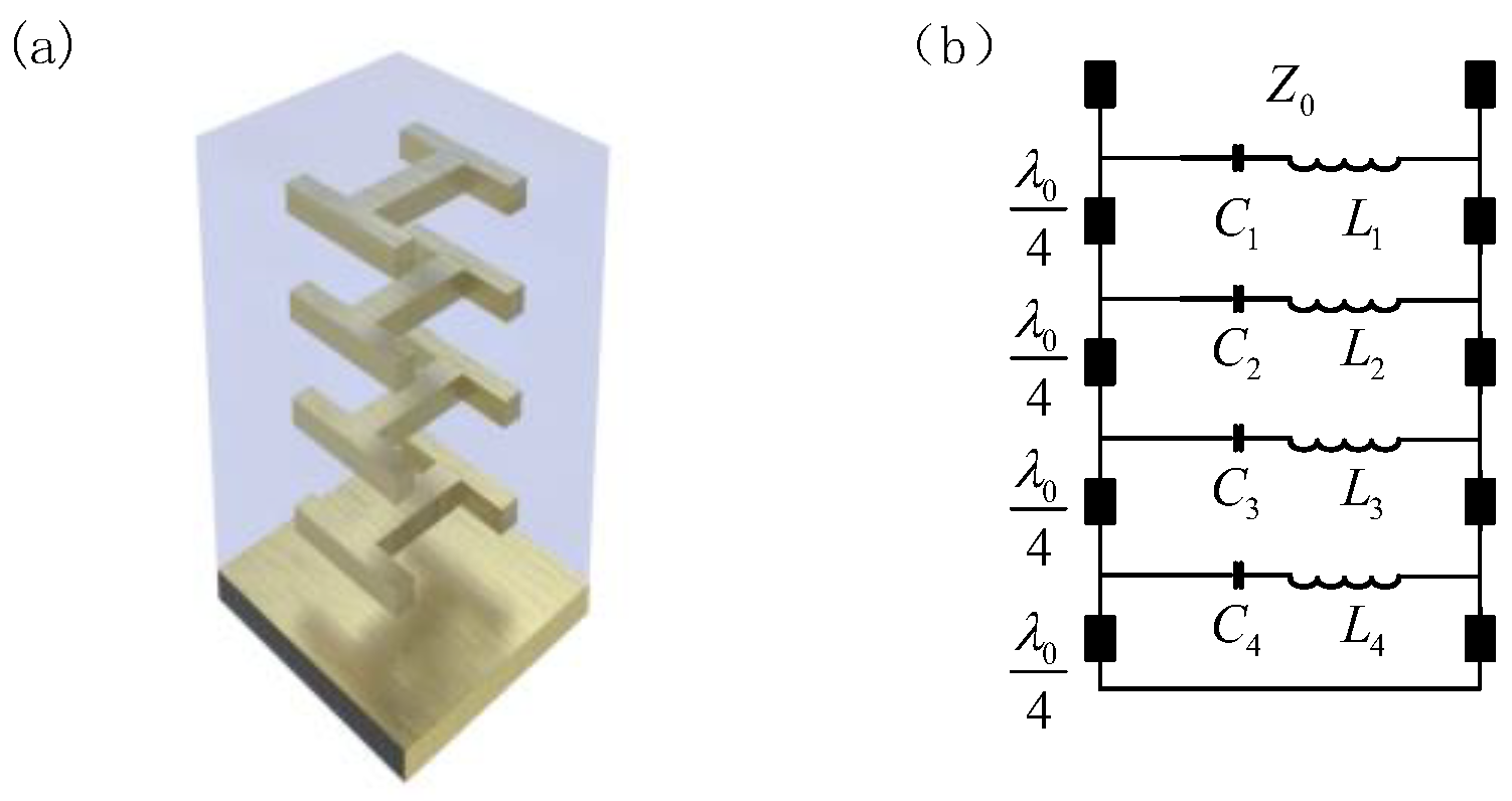
The equivalent circuit model is illustrated in Figure 3. The overall methodology can be divided into two steps: 1. The transformation of a low-pass circuit model into a band-pass circuit model. 2. The conversion of the band-pass circuit model into an equivalent band-pass circuit model physically realizable via multilayer structures. Based on the above derivation, the required capacitance and inductance values are expressed as follows:
where is the group delay of each region, denotes the cutoff frequency of the low-pass circuit shown in Figure 3a, represents the operational bandwidth of the designed band-pass circuit, and is the wave impedance of the free space.
Figure 3.
(a) Low-pass equivalent circuit diagram, (b) band-pass equivalent circuit diagram, and (c) physically realizable band-pass equivalent circuit diagram.
As shown in Figure 3c, the final equivalent circuit topology primarily comprises series-connected capacitors and inductors on the parallel branches, along with parallel admittance inverters. The series capacitors and inductors can be realized by selecting appropriate frequency-selective surfaces (FSSs). The admittance inverters are implemented using quarter-wavelength transformers, operating at the center frequency of the designed bandwidth (75 GHz). The required order of the FSS for the reflectarray depends on its phase variation capability over the operational bandwidth, i.e., the range of the group delay. A wider group delay range necessitates a higher-order FSS. For the quasi-non-diffraction metasurface proposed in this work, which operates across the entire E-band, a four-layer FSS suffices. Based on the derived formulas, Table 2 lists the capacitance and inductance values of the four-layer reflective elements for the three regions.
Table 2.
Capacitance and inductance values of the equivalent circuit models for meta-atoms in three regions.
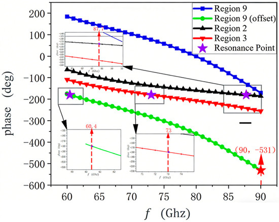
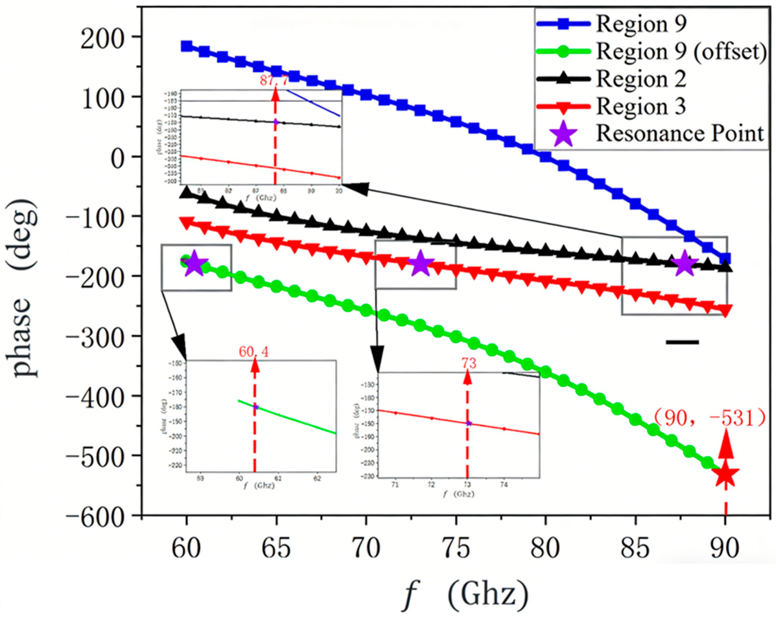
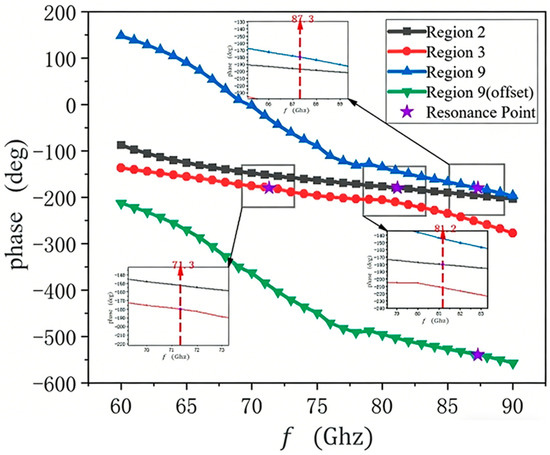
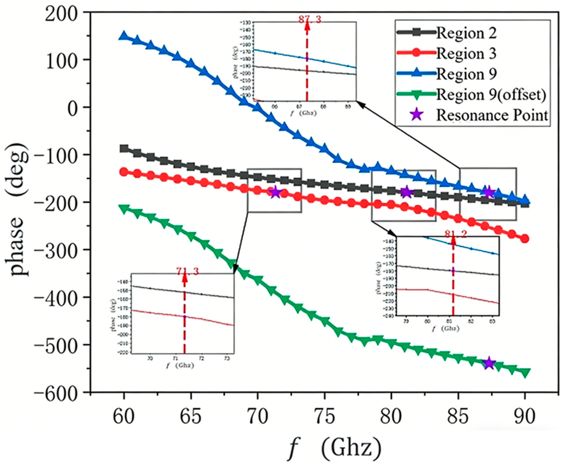
To validate the accuracy of the equivalent circuit, the equivalent capacitance and inductance values from Table 2 were simulated in an Advanced Design System (ADS). The frequency-dependent phase characteristics are plotted in Figure 4. Compared to the ideal phase trends in Figure 2, the slopes of the designed phase curves closely match, and the resonant frequencies for Regions 2, 3, and 9 are 87.7, 73, and 60.4 GHz, respectively, aligning with the values in Table 1. This consistency confirms the fidelity of the proposed circuit model. The genetic algorithm (GA) optimization was employed to fine-tune the extracted C and L values to precisely match the target phase slope. The GA used a population size of 50, a crossover probability of 0.8, and a mutation probability of 0.1. The fitness function was defined as the mean squared error between the phase response of the equivalent circuit model and the target phase from Equation (3) across the 60–90 GHz band. The optimization was terminated when the fitness value changed by less than 0.1% over 50 consecutive generations.
Figure 4.
Frequency-dependent reflection phase characteristics of the meta-atoms in the three regions simulated in ADS.
2.2. Physical Realization of Meta-Atoms
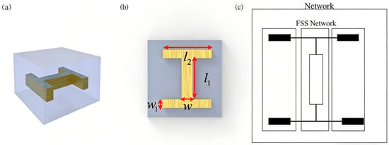
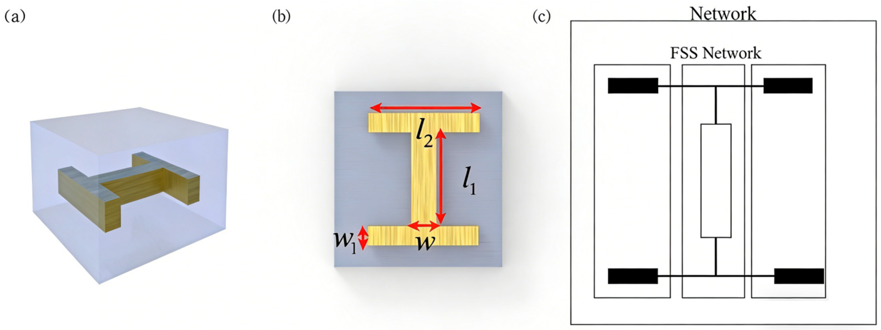
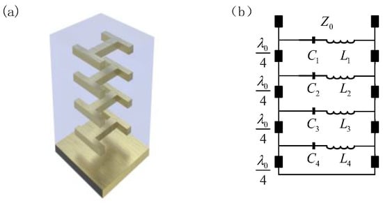
The series-connected capacitors and inductors on the parallel branches are realized using I-shaped FSSs, while the admittance inverters are implemented via appropriately spaced dielectric layers [23]. Since no precise analytical formulas exist to describe the electromagnetic response of the I-shaped FSS, it is essential to investigate the influence of physical parameters on the equivalent capacitance and inductance. Notably, in Ref. [24], the I-shaped FSS was only attached to a single dielectric layer (lower side) with air above, whereas practical applications often require FSSs embedded within multilayer dielectric stacks, as shown in Figure 5a. Figure 5b provides a top view schematic of the FSS embedded in such a multilayer dielectric configuration.
Figure 5.
(a) Front view of the multilayer dielectric FSS. (b) Top view of the multilayer dielectric FSS. (c) Equivalent circuit diagram of the multilayer dielectric FSS.
Therefore, the conventional equivalent circuit analysis method becomes inapplicable, necessitating a revised approach for re-extracting the equivalent circuit of the I-shaped patch embedded within multilayer dielectric stacks. Based on transmission line theory, the dielectric layer can be modeled as a series transmission line, while the FSS is equivalent to a shunt admittance, as illustrated in Figure 5c.
The network T comprises a cascaded connection of the left-side transmission line, the FSS network, and the right-side transmission line. Since only one dielectric layer is added on each side of the FSS, its transmission matrix can be expressed as
Here, represents the overall transmission matrix, denotes the transmission matrix of the dielectric layer, and corresponds to the transmission matrix of the FSS. The transmission matrix of the FSS can thus be expressed as
Here, refers to the inverse of the transmission matrix . Based on the conversion relationship between transmission and impedance matrices, can be expressed as
According to the microwave network theory and the definitions of impedance matrix elements, all four elements of are equal and correspond to the equivalent impedance of the FSS. As derived from the aforementioned equivalent circuit model, the FSS is represented by a series-connected capacitance and inductance. Thus, its series impedance can be expressed as follows:
Since the equivalent capacitance and inductance exhibit instability across the target frequency band, their values are averaged over the operational bandwidth to minimize errors and are further optimized using a genetic algorithm to extract the final C and L.
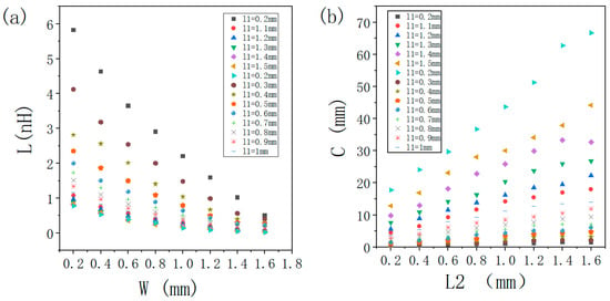
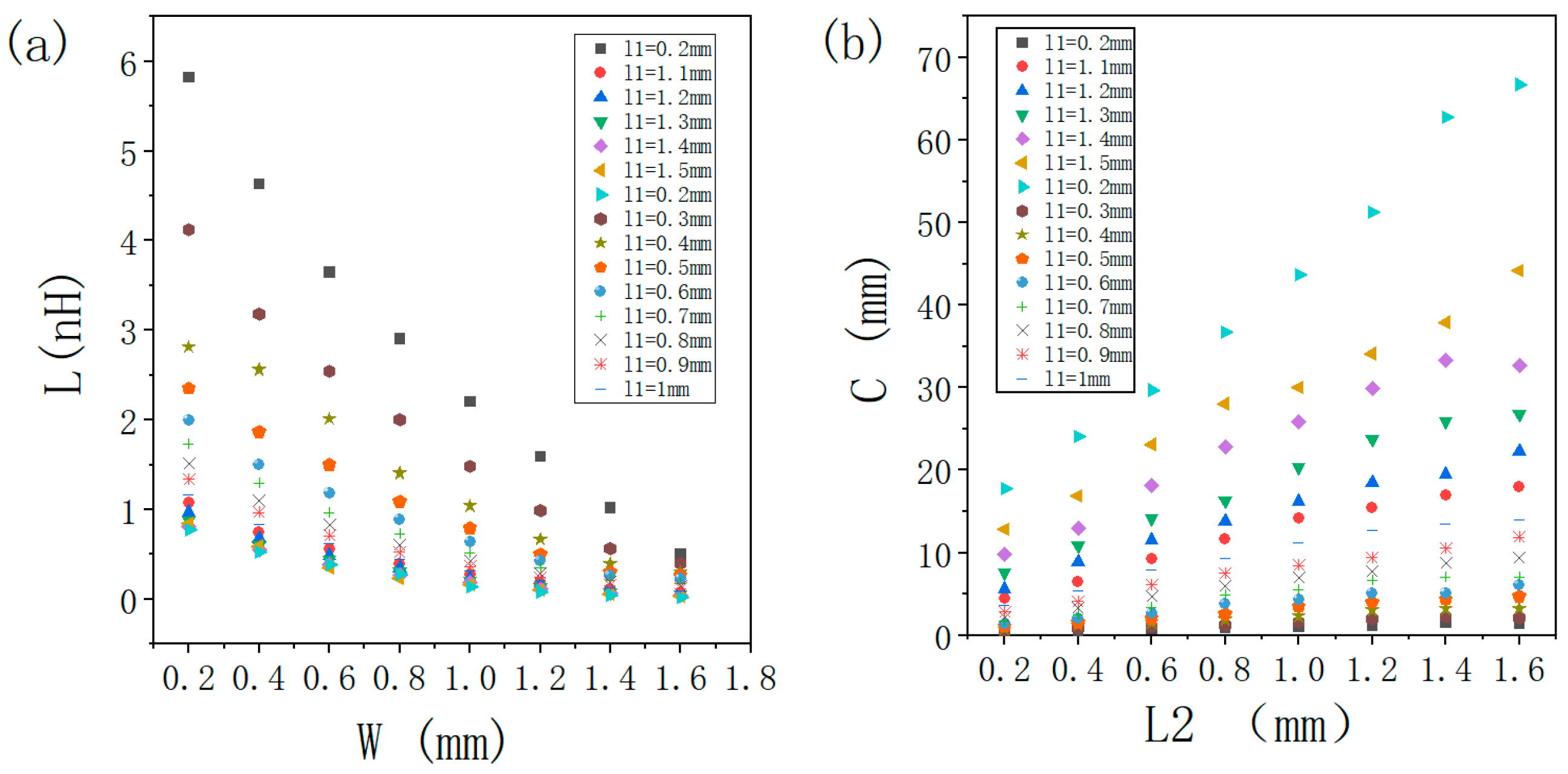
This study reveals that the parameter exerts a significant influence on capacitance while minimally affecting inductance, whereas predominantly modulates inductance with a negligible impact on capacitance. Therefore, is primarily adjusted to tune capacitance, and is optimized to control inductance. The variation trends of capacitance and inductance with respect to and are illustrated in Figure 6.
Figure 6.
(a) Inductance variation versus parameter W. (b) Capacitance variation versus parameter L2.
Table 3 lists the values of , , and corresponding to the three regions. To validate the accuracy of the physical parameters provided in the table, full-wave electromagnetic simulations were conducted in HFSS, with the model structure and equivalent circuit shown in Figure 7. The dielectric layers are modeled as Rogers RO4003C substrates with a relative permittivity (εr) of 3.55, a loss tangent (tan δ) of 0.0027, and a thickness of 0.508 mm. The conductive FSS patterns are modeled as perfect electric conductors (PECs). The full-wave simulations were performed in Ansys HFSS. The simulation domain used Floquet port excitation with master/slave boundary conditions to model the infinite periodic array of the metasurface unit cell. The mesh was set to refinement within the dielectric and near the FSS patterns. An x-polarized plane wave was incident from the z-direction. And Figure 8 illustrates the frequency-dependent phase variations in the three regions. A comparison with the phase variation trends in Figure 4 (simulated in ADS) demonstrates that the overall trends remain consistent. However, the resonant frequencies exhibit a minor low-frequency shift across all regions. Notably, the shift magnitude is small and highly consistent, confirming the accuracy of the extracted physical parameters listed in Table 3.
Table 3.
Key physical parameters of the three regions.
Figure 7.
(a) The structural model of the meta-atom. (b) The corresponding equivalent circuit model for the meta-atom under the x-polarized incidence.
Figure 8.
Frequency-dependent reflection phase characteristics of the meta-atoms in the three regions simulated in HFSS.
3. Simulation Results and Analysis
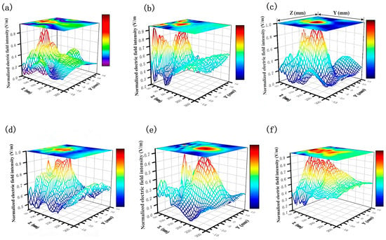
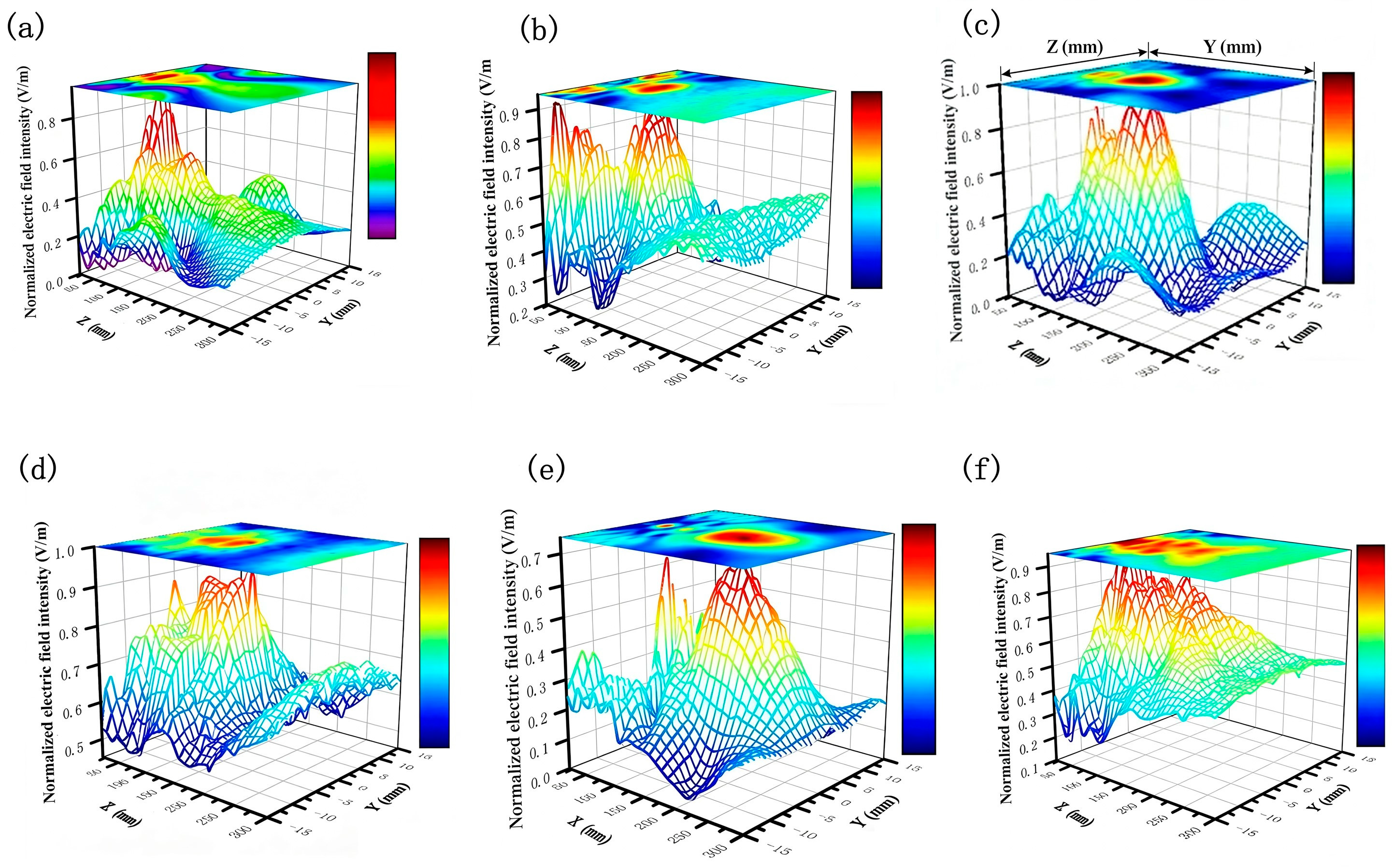
As a proof of concept, a one-dimensional achromatic quasi-non-diffraction metasurface was designed with an overall array periodicity of 80 mm × 80 mm. The one-dimensional model was simulated in Ansys HFSS under x-polarized plane wave illumination along the z-axis. The x-polarized radiation patterns were observed in the yoz plane over 60–90 GHz. Figure 9b,d,f display the electric field distributions in the yoz plane at 60 GHz, 75 GHz, and 90 GHz, respectively. The results demonstrate that quasi-non-diffraction beams are generated at all three frequencies, with minimal variation in the maximum non-diffraction distance. This minor variation arises from slight phase errors introduced during region partitioning and deviations from ideal linear phase curves yet remains within acceptable tolerances.
Figure 9.
Normalized electric field intensity distributions in the yoz plane: (a) 60 GHz without dispersion compensation; (b) 60 GHz with dispersion compensation; (c) 75 GHz without dispersion compensation; (d) 75 GHz with dispersion compensation; (e) 90 GHz without dispersion compensation; and (f) 90 GHz with dispersion compensation.
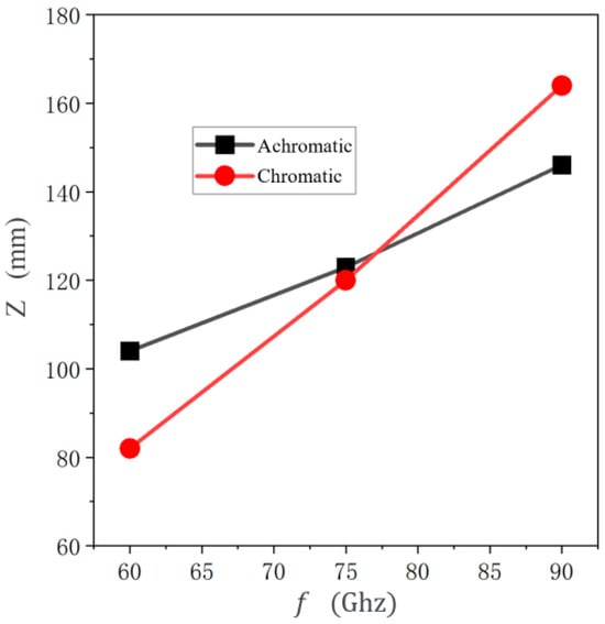
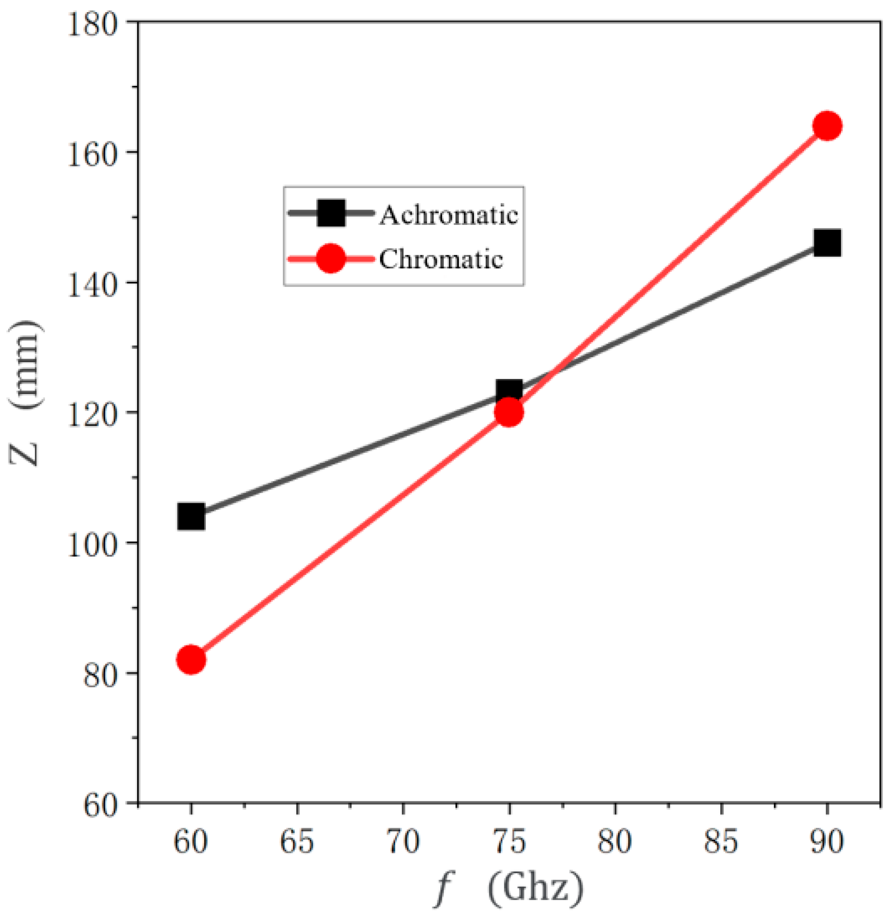
For comparison, a dispersive quasi-diffracting metasurface was designed using dielectric pillars of varying heights for phase adjustments, centered at 75 GHz. Figure 9a,c,e show its electric field distributions at 60 GHz, 75 GHz, and 90 GHz. While quasi-diffracting beams are produced across the band, the maximum non-diffraction distance exhibits significant frequency-dependent variations. Figure 10 shows the trend of the maximum non-diffraction distance for both the proposed achromatic metasurface and a reference dispersive metasurface versus frequency. It can be seen that at the central design frequency (75 GHz), the maximum non-diffraction distances generated by both metasurfaces are nearly identical. However, across the entire 60–90 GHz band, the variation in the maximum non-diffraction distance for the proposed achromatic metasurface is significantly smaller than that of the dispersive metasurface. Specifically, the relative variation for the achromatic design is less than 8%, compared to over 25% for the dispersive design. This demonstrates the effectiveness of our method in suppressing dispersion over a broad bandwidth. Table 4 shows a comparison with previous work in terms of polarization, operating frequency bands, relative bandwidth, etc. The work in this paper can generate a broadband linearly polarized achromatic quasi-diffraction beam while achieving a relative bandwidth of 40%. To the best of the authors’ knowledge, this represents a significant improvement in bandwidth for linearly polarized achromatic quasi-nondiffracting beams at millimeter-wave frequencies compared to existing LP designs and provides a reliable technical solution.
Figure 10.
Frequency-dependent maximum non-diffraction distance of metasurfaces with and without dispersion compensation.
Table 4.
Comparison of different achromatic designs.
4. Conclusions
Based on equivalent circuit theory, this work designs a broadband linearly polarized achromatic metasurface for quasi-non-diffractive wave generation, operating over the 60–90 GHz E-band with a 75 GHz center frequency. The phase response of meta-atoms was optimized via the filter-equivalent circuit model, and full-wave HFSS simulations verified the rationality of the physical structure and its phase characteristics (Figure 8). Simulation results demonstrate that the metasurface generates stable linearly polarized quasi-non-diffractive beams across the entire band: Figure 9 shows well-defined quasi-non-diffractive electric field distributions at 60, 75 and 90 GHz, and Figure 10 quantifies that the relative variation in the maximum non-diffraction distance of the achromatic metasurface is less than 8%, which is far lower than the >25% variation in the conventional dispersive metasurface, confirming effective broadband dispersion suppression. While the simulation results are promising, experimental validation is a vital next step. The proposed structure is amenable to standard printed circuit board (PCB) fabrication processes. The I-shaped FSS patterns can be fabricated using photolithography, and the multiple dielectric layers can be assembled via precision alignment and bonding. The tolerance analysis indicates that the performance is most sensitive to the lengths l1 and l2 of the I-shaped element. A ±5% variation in these dimensions leads to a shift in the resonant frequency of less than 3%, which the bandwidth of the design can accommodate. Future work will focus on the fabrication and measurement of a prototype to validate the simulation results.
As summarized in Table 4, this work achieves a 40% relative bandwidth for linearly polarized achromatic quasi-non-diffractive beams. The proposed method enables precise metasurface design for targeted dispersion compensation, with its validity confirmed by both ADS circuit simulations and HFSS full-wave simulations. Currently, the design process involves a complex multi-step transformation and parameter optimization; future research will focus on streamlining the design workflow, extending this method to other high-power microwave frequency bands, investigating the power handling capacity of the multilayer structure to address dielectric loss and thermal effects, and exploring two-dimensional achromatic quasi-non-diffractive beam generation for practical large-area coverage applications. This study primarily demonstrates the phase engineering and dispersion compensation principle. For practical high-power microwave applications, the reflection efficiency and power handling capacity are critical. The use of low-loss dielectric (Rogers RO4003C) and PEC patterns is beneficial. A preliminary analysis of the reflection coefficient magnitude (|S11|) for the designed meta-atoms shows it remains above −1.2 dB across the band, indicating good impedance matching and low dielectric loss. However, a detailed thermal analysis under high continuous-wave (CW) or pulsed power is beyond the scope of this paper and is identified as essential future work for practical implementation.
Author Contributions
Conceptualization, G.Y., L.C. (Lijie Chen) and F.H.; methodology, G.Y. and L.C. (Lijie Chen); software, G.Y.; validation, L.C. (Lijie Chen) and F.H.; formal analysis, L.X. and M.Y.; investigation, J.C. and L.C. (Liang Chen); resources, Z.L., C.N. and X.D.; data curation, P.W., Y.L. and S.L.; writing—original draft preparation, G.Y.; writing—review and editing, L.C. (Lijie Chen), F.H., L.D. and X.J.; supervision, X.J. and Z.Y. All authors have read and agreed to the published version of the manuscript.
Funding
This research received no external funding.
Data Availability Statement
Data are unavailable due to privacy or ethical restrictions.
Conflicts of Interest
The authors declare no conflicts of interest.
References
- Durnin, J. Exact solutions for nondiffracting beams. I. The scalar theory. J. Opt. Soc. Am. A 1987, 4, 651–654. [Google Scholar]
- Ettorre, M.; Pavone, S.C.; Casaletti, M.; Albani, M. Experimental Validation of Bessel Beam Generation Using an Inward Hankel Aperture Distribution. IEEE Trans. Antennas Propag. 2015, 63, 2539–2544. [Google Scholar] [CrossRef] [Scilit]
- Pavone, S.C.; Ettorre, M.; Casaletti, M. Analysis and Design of Bessel Beam Launchers: Transverse Polarization. IEEE Trans. Antennas Propag. 2021, 69, 5175–5180. [Google Scholar] [CrossRef] [Scilit]
- Comite, D.; Valerio, G.; Albani, M. Exciting Vorticity Through Higher Order Bessel Beams with a Radial-Line Slot-Array Antenna. IEEE Trans. Antennas Propag. 2017, 65, 2123–2128. [Google Scholar] [CrossRef] [Scilit]
- Zhao, Z.; Ding, X.; Zhang, K. 2-D Airy Beam Generation and Manipulation Utilizing Metasurface. IEEE Trans. Magn. 2022, 58, 1–5. [Google Scholar]
- Li, J.; Zhong, M. Airy Beam Multifunctional Terahertz Metasurface. IEEE Photon. Technol. Lett. 2023, 35, 245–248. [Google Scholar] [CrossRef] [Scilit]
- Huang, Y.; Li, J.; Xu, H.X. Experimental Demonstration of Microwave Two-Dimensional Airy Beam Generation Based on Single-Layer Metasurface. IEEE Trans. Antennas Propag. 2020, 68, 7507–7516. [Google Scholar] [CrossRef] [Scilit]
- Vasiljevic, J.; Timotijevic, D.V.; Jovic, S.D.M. Light propagation in disordered aperiodic Mathieu lattices generated with two different randomization methods. In Proceedings of the Nonlinear Optics and its Applications, Strasbourg, France, 3–7 April 2022; p. 41. [Google Scholar]
- Bao, L.; Wu, R.Y.; Fu, X. Multi-Beam Forming and Controls by Metasurface with Phase and Amplitude Modulations. IEEE Trans. Antennas Propag. 2019, 67, 6680–6685. [Google Scholar] [CrossRef] [Scilit]
- Chu, H.; Li, Q.; Liu, B. A Hybrid Invisibility Cloak Based on Integration of Transparent Metasurfaces and Zero-Index Materials. Light Sci. Appl. 2018, 7, 50. [Google Scholar] [CrossRef] [Scilit]
- Zhong, Y.C.; Cheng, Y.J. Generating and Steering Quasi-Nondiffractive Beam by Near-Field Planar Risley Prisms. IEEE Trans. Antennas Propag. 2020, 68, 7767–7776. [Google Scholar] [CrossRef] [Scilit]
- Zhi, J.; Hu, B.; Guo, Y. Generation of non-diffractive Lommel beams based on all-dielectric metasurfaces. Opt. Express 2022, 30, 42214–42223. [Google Scholar] [CrossRef] [Scilit] [PubMed]
- Wu, X.; Cao, H.; Peng, J.; Meng, Z. Terahertz quasi non-diffraction Bessel vortex beam generation using three lattice types reflective metasurface. Opt. Express 2022, 30, 31653–31668. [Google Scholar] [CrossRef] [Scilit]
- He, X.; Yang, Y.; Deng, L. 3D Printed Sub-Terahertz All-Dielectric Lens for Arbitrary Manipulation of Quasi-Nondiffractive Orbital Angular Momentum Waves. ACS Appl. Mater. Interfaces 2021, 13, 20770–20778. [Google Scholar] [CrossRef] [Scilit]
- Huang, H.; Wang, J. Switchable terahertz orbital angular momentum Bessel beams based on spin-decoupled multifunctional reflective metasurfaces. Opt. Express 2023, 31, 34855–34870. [Google Scholar] [CrossRef] [Scilit]
- Song, N.; Xu, N.; Shan, D. Broadband Achromatic Metasurfaces for Longwave Infrared Applications. Nanomaterials 2021, 11, 2760. [Google Scholar] [CrossRef] [Scilit]
- Aieta, F.; Kats, M.; Genevet, P. Multiwavelength Achromatic Metasurfaces by Dispersive Phase Compensation. Science 2015, 347, 1342. [Google Scholar] [CrossRef] [Scilit]
- Wang, S.; Wu, P.C.; Su, V.C. Broadband Achromatic Optical Metasurface Devices. Nat. Commun. 2017, 8, 187. [Google Scholar] [CrossRef] [Scilit]
- Zhang, S.; Huo, P.; Wang, Y. Generation of achromatic auto-focusing Airy beam for Visible light by an all-dielectric metasurface. J. Appl. Phys. 2022, 131, 043104. [Google Scholar] [CrossRef] [Scilit]
- Chen, W.T.; Khorasaninejad, M.; Zhu, A.Y. Generation of wavelength-independent subwavelength Bessel beams using metasurfaces. Light. Sci. Appl. 2017, 6, e16259. [Google Scholar] [CrossRef] [Scilit] [PubMed]
- Zhong, Y.C.; Cheng, Y.J. Ka-Band Wideband Large Depth-of-Field Beam Generation Through a Phase Shifting Surface Antenna. IEEE Trans. Antennas Propag. 2016, 64, 5038–5045. [Google Scholar] [CrossRef] [Scilit]
- Zhong, Y.C.; Cheng, Y.J. Wideband Quasi-Nondiffraction Beam with Accurately Controllable Propagating Angle and Depth-of-Field. IEEE Trans. Antennas Propag. 2017, 65, 5035–5042. [Google Scholar] [CrossRef] [Scilit]
- Delafkar, H.; Pirhadi, A. An Accurate Method for Synthesis of Reflecting Elements to Design Wideband Reflectarray Antenna. IEEE Trans. Antennas Propag. 2018, 66, 2392–2400. [Google Scholar] [CrossRef] [Scilit]
- Costa, F.; Monorchio, A. An Overview of Equivalent Circuit Modeling Techniques of Frequency Selective Surfaces and Metasurfaces. Appl. Comput. Electromagn. Soc. J. 2014, 29, 960–976. [Google Scholar]

Disclaimer/Publisher’s Note: The statements, opinions and data contained in all publications are solely those of the individual author(s) and contributor(s) and not of MDPI and/or the editor(s). MDPI and/or the editor(s) disclaim responsibility for any injury to people or property resulting from any ideas, methods, instructions or products referred to in the content. |
© 2026 by the authors. Licensee MDPI, Basel, Switzerland. This article is an open access article distributed under the terms and conditions of the Creative Commons Attribution (CC BY) license.