


Abstract
Securing resource-constrained Industrial Internet of Things (IIoT) devices requires guarantees of integrity and confidentiality. This paper presents a security framework developed under the CERTIFY project to document and justify trustworthy execution of sensitive software running on resource-constrained devices. Our architecture model assumes the presence of a separation kernel, that employs hardware Memory Protection Units to enforce Memory isolation and mediate communications during boot, provisioning, and run-time. On the other side, the paper does not cover implementation aspects, but leaves them to the choice of the user intending to adopt the proposed solution architecture. To systematically show the trustworthiness of this proposed architecture, we develop an assurance case using Goal Structuring Notation: we map system requirements to architecture-specific security objectives and introduce a novel “attacker action” graphical element to explicitly integrate threat modeling into our arguments. The resulting assurance case provides a structured, auditable, and reusable foundation architecture for the secure implementation of the CERTIFY IIoT framework.
1. Introduction
The CERTIFY European project [1,2] (funded by EU grant agreement no. 101069471 and Swiss SERI grant agreements no. 22.00165 1292 and 22.00191) provides tools and mechanisms to enforce and maintain cybersecurity of a complex network of Industrial Internet of Things (IIoT) nodes, encompassing their entire lifecycle. As part of the project’s scope, CERTIFY designed, implemented, and demonstrated a secure architecture for Industrial Internet of Things nodes. Despite different capabilities offered by nodes of different class, the CERTIFY project has the objective of ensuring baseline services and guarantees of trustworthiness, on top of which the overall CERTIFY architecture can be built and operated securely. The current work reports on the efforts made in the scope of CERTIFY to provide evidence of the design principles behind key building blocks in order to increase assurance on claimed guarantees.
The target application domain of IIoT demands for providing usable justification of adequacy of the security design to satisfy the claimed set of security properties against a defined threat landscape. This usability requirement is formulated with the perspective of increasing customer trustworthiness, by producing structured and auditable justification linked to architectural aspects, as well as supporting certification efforts or better documentation of cybersecurity aspects, also considering traceability and maturity management. As a consequence, the objectives of the current work are (1) the definition of a reference security architecture model for an embedded platform, and (2) the definition of a method and a fully executed example, for the production of technical documentation with evidence that the proposed architecture provides adequate mitigation against a defined threat landscape, relying on a set of Platform Security Enablers.
The current work adopts Goal Structuring Notation (GSN) as it offers a clear, graphical method for structuring complex arguments, improving comprehension among stakeholders, enhancing traceability between requirements and evidence, supporting modularity for better maintenance and reuse, and enabling explicit documentation of context and assumptions. This structured approach makes assurance cases more robust, efficient, and suitable for regulatory approval in safety-critical industries. GSN notation supports modularity and, therefore, facilitates reuse by referring to common sub-goals in different parts of the assurance case, thus reducing effort and improving usability of documentation. GSN has been largely used to formulate functional and safety arguments and, to a smaller extent, cybersecurity arguments. It has also been subject to standardization efforts [3]. The approach proposed in the current paper distinguishes itself by applying these principles to a low-end, open-hardware IIoT platform, and introducing a novel “attacker action” notation to make threat modeling explicit in the GSN arguments. In addition, the current work has the intent of providing reusable assurance arguments, by decomposing them into objectives and relying on a reference architecture. Overall, this is meant to be a further contribution in the direction of adopting GSN notation for cybersecurity applications.
The current work attempts at developing assurance cases guided by architectural and behavioral elements. For this reason, it has been necessary to define, at high level, both the hardware and software architectures of the considered IIoT node, as well as to represent the operational behavior. This approach has led to the creation of models to achieve the desired abstraction level that would, on one side, retain sufficient details for justifying assurance, and on the other side, be adequately abstract to manage the possible explosion of complexity of the assurance case.
While the primary focus of this paper is to justify the role of the different security functions in achieving the target security properties, it is recognized that applying this security architecture in practice may face significant costs. A cost–benefit analysis remains a necessity for real-world deployments. Consequently, the reference architecture should be viewed as a baseline; adopters planning to implement it can remove, reduce, or modify individual security measures to accommodate the cost constraints and needs of the specific domain.
The rest of this paper has been structured as follows: Section 2 provides an overview of related work, Section 3 describes the high-level security architecture of the target IIoT device, Section 4 defines the security requirements to be satisfied, Section 5 details the translation of the security requirements into architecture-dependent security objectives, Section 6 and Section 7 specify at high level the design decisions taken at platform level to satisfy the security requirements, Section 8 explains the approach taken for documenting the assurance cases, Section 9 consists of the actual assurance case, covered by several GSN diagrams, and Section 10 provides a summary of the paper results and next steps.
2. Related Work
The research reported in this paper is built on two key foundations that drive both the security design and the demonstrated assurance approach. First, we rely on the separation kernel concept that Rushby [4] originally developed, which CERTIFY calls “security monitor” and implements in a manner that is suitable for resource-constrained IIoT devices. Second, we draw from Kelly and Weaver’s [5] work on GSN, though our CERTIFY assurance case uses a simplified graphical notation that is better suited for documenting IIoT platforms.
Several models for isolated execution have been defined in the literature. Rushby [6] was the first to address the safety and security implications of transitioning from distributed systems to a single platform supporting multiple functions, introducing the concept of a separation kernel. Rushby’s separation kernel is intended to enable the coexistence of different levels of security on the same platform by dividing the platform into multiple isolated partitions, interacting only by means of carefully controlled interfaces. The concept of a separation kernel allowing multiple applications with different levels of security to be executed on the same platform was later incorporated in the so-called MILS architecture (Multiple Independent Levels of Security) [6,7], a high-assurance security architecture based on the concepts of isolation and information-flow control, which lets multiple applications with different security levels run on the same platform without interfering with each other. The NSA Separation Kernel Protection Profile (SKPP) [8] establishes the security requirements for a separation kernel. Separation kernels may be represented by formal security models [9], which are the abstraction of the concrete kernel implementations. The security of a separation kernel is usually claimed by demonstrating that its security model preserves a set of formally specified security policies or properties. Two typical security policies for MILS architecture are the inter-partition flow policy (IPFP) and the partitioned information-flow policy (PIFP). Data separation properties require instead that resources of a partition must be completely independent of other partitions (MASK, ED). Information flow security properties are instead state-based properties (non-interference [10]).
The use of structured arguments to demonstrate security properties is a well-established practice in high-assurance systems. Using GSN for security arguments in separation kernels is a proven approach that has been developed and tested in different research settings. We follow the pattern-based reasoning framework that d’Amato and Massacci [11] created for MILS architectures [12], using similar structured arguments to show how the CERTIFY platform maintains its security properties. This paper was inspired also by the work from the D-MILS project, where GSN has been used to represent key design principles behind the MILS concept [13] and demonstrated on cryptographic applications. The main approach of building security assurance cases for separation kernels, as shown by Ledge and Atkey [14], gives us our core methodology, though we have adapted it for the specific challenges and needs of IIoT device environments. While our current work focuses on self-defined security policies rather than formal certification processes, we share the same basic goal that Hanebutte and Lescher [15] described: building convincing security cases that are grounded in established industry standards. Our structured approach to building assurance cases follows the systematic practices that Goodenough et al. [16] laid out, making sure we have clear, evidence-backed arguments. Our specific focus on security properties matches the specialized methods that Hawkins et al. [17] presented for explicitly reasoning about security threats and how to counter them. For future improvements, the confidence argument patterns that Bloomfield and Khlaaf [18] explored suggest ways we could develop higher-level arguments about whether our assurance case is sufficient and robust enough. Our entire documentation approach adheres to the current GSN Community Standard [3], while potentially adding specialized tools, as Denney and Pai [19] discussed, could further strengthen how we manage and validate the complex argument structures we have developed for the CERTIFY platform.
While this paper builds its assurance case mainly through design-time evidence and structured logical arguments, it fits into a broader field of increasingly advanced verification techniques and architectural innovations. The formal verification work that Klein et al. [20] achieved with the seL4 kernel, a high-assurance microkernel designed for security- and safety-critical systems, sets the current standard for proving separation properties. seL4 defining feature is a comprehensive formal verification story, which provides a mathematical proof that its C-code implementation is functionally correct with respect to its high-level specification. This verification, unique in the OS kernel space, demonstrates that the kernel is free from an entire class of implementation bugs and enforces strong security properties, such as integrity and confidentiality. seL4’s design, which includes a minimal trusted computing base and capability-based access control, makes it a provably secure foundation for partitioning systems and running mixed-criticality workloads. This enables a single platform to safely host diverse applications, from highly sensitive software to untrusted code, ensuring strict isolation between them. The work of this paper is different from seL4 in a few aspects: (1) it targets a different and more constrained class of embedded devices, without Memory management unit, (2) it relies on much less formalized but more human readable GSN-based artifacts, (3) it covers a broader scope than only separation, and (4) it is meant to provide reusable artifacts in terms of GSN arguments, applicable to a more heterogeneous class of hardware platforms. Also, the compositional security analysis approaches that Cofer et al. [21] discussed align well with the trust assumptions behind the CERTIFY platform, which fundamentally depend on the certified correctness of individual hardware components including the CPU, system bus, and MPU. The possibility of combining formal verification evidence with GSN frameworks, as Myreen and Gordon [22] explored, points to promising ways we could increase the assurance levels of platforms like CERTIFY in future developments.
Our general reliance on hardware-enforced separation through Memory Protection Unit (MPU) technology makes the approach quite applicable to several microcontroller-class devices. In our specific case, we focused on developing our IIoT solution based on a RISC-V-derived architecture, but that is not a mandatory aspect for our assurance story and also, several other commercially available IIoT devices share a similar architecture. A different approach is the one characterizing the ARM TrustZone security architecture, for which it is possible to find a detailed analysis in Pinto and Santos [23], which not only relies on Memory Protection but also on augmented execution modes and distinguishing CPU execution states across security domains. Such a design is beyond the scope of this work but may be a nice extension for the application of our results.
The approach we use in this paper not only relies on architectural security and assurance cases documentation, but also on inherently secure software development practices. The way modern programming languages can help with security in a separation kernel is demonstrated by how the Tock operating system uses Rust for in-kernel protection, as Levy et al. [24,25] described. The Memory safety guarantees that Rust provides, as Jung et al. [26] analyzed in detail, give us extra layers of fine-grained access control that strengthen the overall security posture.
3. CERTIFY Low-End IIoT Device
The current section is dedicated to the definition of a reference security architecture for the CERTIFY IIoT node, represented in Figure 1. The figure contains three main types of blocks: (1) applications, hosted on the node to accomplish the end-user tasks, (2) CERTIFY Security Services, hosted on the IIoT node to support the CERTIFY security ecosystem and enforce established security policies, and (3) Platform Security Enablers, offering support for the CERTIFY Security Services execution.
Figure 1.
Key elements of the CERTIFY IIoT Platform (from D4.1).
The CERTIFY Security Services play a key role in establishing trust in the IIoT node and in the hosted applications. One of the roles of Platform Security Enablers is to guarantee to the CERTIFY Security Services the following security properties: (1) authenticity, (2) integrity, (3) confidentiality of data required for offering the security services, such as crypto material, and (4) confidentiality and authenticity of code realizing the security services, e.g., measurement logic for attestation. Besides protection of the CERTIFY Security Services, the Platform Security Enablers offer several other basic security support functions, typically implemented in hardware for improved security.
3.1. IIoT Node Architecture
Figure 2 represents a logic schematization of the CERTIFY IIoT node architecture model. CERTIFY assumes that the IIoT platform includes trustworthy hardware modules and platform software, on top of which application SW including trusted and untrusted applications (Apps) can be deployed. As expected, CERTIFY Security Services shall be trusted Apps. The proposed model guarantees separation among Apps to enforce the above-mentioned security properties on CERTIFY Security Services, and it is aligned to the requirements of notable security specifications (MILS, SKPP) [7]. Then, it allows user-specified information flows between Apps, Peripherals, and separation kernel (Kernel or Security Monitor, from now on). The CERTIFY IIoT Configurable Platform guarantees that only user-specified information flows are allowed, and no other information flow can be established by Apps/Peripherals.
Figure 2.
CERTIFY IIoT Configurable Platform and its key Configuration Elements.
At the hardware level, the proposed model considers a single-core IIoT node, including the following elements:
- A central processing unit (CPU) that is in charge of executing the platform software stack. The CPU provides at least one privileged mode of execution and one normal mode of execution. It includes hardware support for Memory access control, usually by means of a dedicated MPU regulating access to the rest of platform resources.
- System interconnect (BUS), an on-chip communication infrastructure supporting the communication between the CPU and the other platform resources (memories and Peripherals).
- Memory elements, including ROM and RAM memories (usually on-chip) and non-volatile memories (possibly off-chip). The access to a Memory element may be mediated by a Memory controller, not represented in the picture.
- Peripherals, including critical computing modules that are part of the Platform Security Enablers (crypto primitives) and other non-critical Peripherals (e.g., communication interfaces). All Peripherals are Memory-mapped.
Several real-world platforms are aligned to the proposed model (for example, single-core nodes based on the ARM Cortex M family of processors) [27]. At the software level, the platform assumes the existence of two types of software components:
- The Kernel, i.e., a software module executing in a privileged mode of the CPU that is in charge of platform configuration and that controls the access to the platform resources. The Kernel is responsible for the configuration of the MPU, scheduling of user Apps, management of CPU exceptions. The Kernel is also in charge of mediation of access to Peripherals. The latter assumption requires the Kernel to include Peripherals drivers.
- The Apps, that have their own required level of security, may be subject to vulnerabilities, and possibly include security services.
Note that including Peripherals drivers in the Kernel is only one possible approach—a different approach considers user-level drivers. The decision has been to focus on the first approach (Kernel-mediated access), as the second does not differ much from general access control for Apps (the Kernel is responsible for granting access to the Peripherals, as part of the System Security Policy).
3.2. System Operational View
Figure 3 represents a dynamic, or “operational”, view of the system as a state machine, where states and transitions are identified based on the security requirements and on the assurance objectives introduced earlier in the text. In this section, an overview is provided, while a more thorough description of the abstract system execution steps, represented by transitions, will be given in Section 7.
Figure 3.
Device operational states.
As a preliminary assumption, we establish a perimeter (represented with a red dashed line) that is trusted, meaning that an attacker is not able to interact with the system in the trusted domain. Typically, this perimeter corresponds to the manufacturer’s premises (design, production, …). Beyond such a perimeter, the environment is untrusted because the attacker is able to interact with the system.
The first state of interest, “Ready”, is where the system is still off, the volatile Memory MEM is clean, the non-volatile read-only Memory ROM contains platform boot code and the non-volatile Memory NVM contains code and data, organized according to the model of Section 6.2.
On power-on, a Trusted Boot procedure loads the Kernel to Memory and starts its execution. Kernel Initialization takes place with several activities, among which (i) setting Kernel data structures and Memory access policies, (ii) loading in advance all the Apps (fixed and known a priori) and Peripherals drivers, (iii) loading the information necessary to allow shared Memory-based communication and to set Apps Memory access policies on demand.
At this point, the system, unless powered off or sent back for maintenance/repairs, enters an ideal cycle of alternation between Security Monitor (SM) and Apps execution, where the former is responsible for scheduling Apps, handling communication between Apps and with Peripherals, and managing Memory access control by relying on the MPU capabilities. Apps execute on the device as if they were alone, except for the user-specified information flows that explicitly allow App-to-App communications (and, therefore, awareness of other Apps).
4. Security Requirements
The main security requirements are summarized by the following list:
- Manufacturer Provisioning:
- (a)
- The platform allows the configuration of the following elements at provisioning time: (1) Boot logic, (2) Apps configuration, (3) Keys for authentication of boot image, Kernel image, and Trusted Apps images, and (4) allowed information flows.
- (b)
- Configuration is protected to guarantee integrity and authenticity.
- Boot and Initialization:
- (a)
- Kernel loading:
- i.
- The Kernel image has its integrity successfully verified by means of a signature, before execution.
- ii.
- The Signature Key is protected from tampering (and disclosure, if it is a symmetric key).
- (b)
- Apps loading:
- i.
- Authenticated Apps have their integrity successfully verified by means of a signature, before execution.
- ii.
- The Signature Key is protected from tampering (and disclosure, if it is a symmetric key).
- (c)
- Kernel/Apps Memory and access control policy (System Security Policy) is established:
- i.
- Apps and Kernel data in Memory are set as disjoint and there is no default access other than the one for the owner.
- ii.
- The communication policy (Com Policy) is established so that Apps, Kernel, and Peripherals can exchange data by using shared Memory regions (note that interaction of Apps with Peripherals is mediated by the Kernel).
- (d)
- System Security Policy cannot be modified after Kernel Initialization.
- Kernel Execution (after “Boot and Initialization”):
- (a)
- The Kernel is subject to System Security Policy during execution:
- i.
- Apps’ data and code Memory are kept isolated, protecting confidentiality and integrity of ongoing computations (except for regions authorized by Com Policy).
- (b)
- If an App A requests interaction with an App or Peripheral B:
- i.
- The Kernel should be the intermediary to authorize and establish communication (as per Com Policy).
- ii.
- If an App is authenticated, then the other App should have the guarantee of its identity.
- (c)
- During Kernel execution, if a Peripheral has a driver subject to a vulnerability, this does not affect the enforcement of the System Security Policy and Com Policy.
- Apps Execution:
- (a)
- Apps are subject to System Security Policy during execution:
- i.
- Other Apps’ data and code Memory are kept isolated, protecting confidentiality and integrity of ongoing computations (unless for regions authorized by Com Policy).
- ii.
- Kernel data and code integrity is guaranteed.
5. Assurance Objectives
The definition of the assurance case for the IIoT device has the following main objectives:
- Demonstrate that, starting from the device in OFF state, Trusted Boot and Kernel Initialization can bring the device to a known secure state satisfying the System Security Policy, considering the exceptions allowed by the Com Policy, independently from what an attacker can do.
- Demonstrate that, once the device is initialized and ready, any execution continues to satisfy the System Security Policy, considering the exceptions allowed by the Com Policy, independently from what an attacker can do.
Below, we summarize key properties ensuring satisfaction of the security requirements of Section 4.
- Secure boot: Ensures that only authenticated and integral binaries can be loaded and executed on the platform. In case of an unexpected condition (i.e., a modification in the code is detected), the boot process is interrupted.
- Isolated execution: Ensures Apps execute completely isolated from others and guarantees that any code and data is protected at run-time. It is guaranteed by a Security Monitor running on the platform.
- Secure scheduling: Ensures that Apps are executed on the platform according to an expected plan, guaranteeing their availability and responsiveness. For this reason, the scheduler is usually part of the Security Monitor, executed in the privileged state and generally designed to be preemptive.
- Secure communication, in accordance with user-specified information flows:
- –
- Between Apps—i.e., across the boundaries of the isolated execution environment in which the applications run.
- –
- Between Apps and I/O elements, providing access to Peripherals for the Apps.
- –
- Both types of communication shall preserve Memory and time isolation, as well as keep the data structures supporting the communication protected.
The definition of the assurance case will be articulated in the following phases:
- Definition of a platform architecture model and of an abstract behavioral model of the platform operations (including boot, initialization, Kernel, Apps)—addressed in Section 6.
- Definition of an adversary model—i.e., a description of what an attacker can do, in terms of its capabilities—addressed in Section 5.2.
- Derivation of evidence for the above-mentioned assurance objectives by means of an assurance case structured as an (implicitly) inductive proof:
- (a)
- The base case consisting in demonstrating that the system can achieve a secure state—referred to as the Security Invariant (satisfying the System Security Policy, considering the exceptions allowed by the Com Policy).
- (b)
- The inductive step, consisting in demonstrating that, starting from any secure state, the Kernel can preserve the Security Invariant, for any next state allowed by the System Security Policy, considering the exceptions allowed by the Com Policy.
5.1. Trust Assumptions and Certification
In order to provide the desired guarantees, some assumptions are made on trustworthiness of selected components. Such trust can be provided by certification means. Figure 4 provides a slightly refined architectural view (where the Kernel is decomposed into building blocks) and shows in green the trusted components. Similarly, in red are shown untrusted components.
Figure 4.
Trust and distrust assumptions.
Below, the trust assumptions are summarized:
- Hardware
- –
- Trusted—certified correct and with no vulnerabilities:
- *
- CPU, BUS, MPU, ROM, HW Crypto Primitives.
- *
- BUS guarantees authenticity of sender/recipient and integrity of data.
- *
- ROM immutable after factory write.
- –
- Semi-trusted—certified correctness and limited vulnerabilities:
- *
- Kernel:
- ∙
- Partition Manager (PM) is correct with respect to specifications, may have vulnerabilities;
- ∙
- Scheduler (SC) is correct with respect to specifications, may have vulnerabilities;
- ∙
- Support Services (SR) are correct with respect to specifications, may have vulnerabilities (drivers may be incorrect and have vulnerabilities).
- *
- NVM / MEM:
- ∙
- Read and write can be trusted.
- *
- Other Peripherals:
- ∙
- Firmware/hardware behavior may have vulnerabilities;
- ∙
- They can be trusted on access to mapped Memory;
- Software
- –
- Trusted—certified correct and with no vulnerabilities:
- *
- ROM, Init, all configuration data.
- –
- Semi-trusted—certified correctness and limited vulnerabilities:
- *
- Security Monitor is correct but may have some vulnerabilities affecting its behavior.
- *
- Support Services—Peripherals drivers can be compromised due to a vulnerability.
- –
- Untrusted:
- *
- Apps can be compromised due to vulnerabilities.
- *
- Apps can be malicious (including impersonation of other Apps).
5.2. Attacker Model
Leveraging Figure 4, it is possible to describe the assumptions on the attacker capabilities. In particular, the attacker has the following:
- Limited physical access to the device
- –
- Can read and write on NVM;
- –
- Can interact with Peripherals on a physical interface;
- –
- Cannot perform physical attacks, such as fault injections, probing, physical side channels, physical sniffing, etc.
- Logical access to a number of components
- –
- Through an App, can read and write on MEM, subject to MPU access control;
- –
- From external devices, can interact with Other Peripherals and use Other Peripherals to perform malicious activities;
- –
- Through an App, can send inputs to other Apps.
Relevant threat scenarios are listed as follows:
- Kernel or Apps binaries (and related data) can be compromised on NVM;
- An untrusted App can compromise integrity or confidentiality of Kernel or other Apps data and code;
- An authenticated App is affected by a vulnerability that allows an attacker to take control over it and try to use it to compromise integrity or confidentiality of Kernel or other Apps data and code;
- An untrusted App tries to impersonate an authenticated App;
- A malicious external actor uses Other Peripherals to gain unauthorized access to Kernel Memory regions and compromise integrity of stored data and code.
6. Platform Abstraction Model
The current section describes the platform at a defined level of abstraction that allows the assurance case to be feasible for documentation.
6.1. Hardware Platform Model
As shown in Figure 5, we assume the system is composed of the following hardware elements:
Figure 5.
HW platform model.
- A single-core CPU, without HW support for multithreading;
- A non-volatile and non-modifiable (read-only) Memory (ROM);
- A volatile Memory (MEM);
- A non-volatile Memory (NVM);
- A set of Peripherals, including devices implementing hardware cryptographic primitives;
- A BUS, that allows data transfer between CPU and Memory, storage and Peripherals;
- An MPU, interposed between the CPU and the BUS.
6.1.1. Memory
A single address space (Memory) includes MEM and Peripherals’ registers (see below); access to this space is mediated by the MPU. The MPU monitors and controls access to the entire Memory, including all Memory-mapped Peripherals.
6.1.2. CPU
The CPU performs in-order execution in one of two modes: user mode (U-mode) or machine mode (M-mode). The CPU requests Memory access through the bus with either execution rights (during the fetch stage of the instruction cycle) or read/write rights (during the execution stage); the requests are received by the MPU, that monitors access to any Memory-mapped Peripheral on the BUS, based on access rights associated to the corresponding Memory location.
6.1.3. Peripherals
Peripherals, for our purposes, can be seen as state machines, with a local Memory in the form of one or more registers. By design, direct Memory access is not allowed, and Peripherals have only access to their own registers. As mentioned, some of the registers are Memory-mapped to the common address space and can be accessed by the CPU through the BUS, subject to MPU constraints.
6.1.4. MPU
As represented in Figure 6, the MPU evaluates Memory access requests from the CPU. Memory access requests contain target address and access type, plus current execution mode as contextual information. Essential components of the MPU are its Configuration Registers (MPU_CR), storing the information necessary to determine whether an access request should be granted or refused, in which case an exception is raised to the CPU.
Figure 6.
MPU model.
Each MPU Configuration Register entry contains the following information: allowed CPU execution mode (user or machine), start Memory address, size of the Memory region, allowed access rights (one or more among execute, read, write), locked bit. For a given Memory access request, if the current execution mode corresponds to the required one, the target address falls into the region determined by start address and size, and the requested access right is among the allowed ones, then there is a match, and the request can be granted. Register content can be modified only by the CPU executing in M-mode, unless the locked bit is set. In such a case, the register cannot be written on until the next system reboot.
Note that, in presence of an access request, MPU Configuration Register entries, intended as an array of registers, are evaluated in order, so that entries with smaller index have priority over those with larger index; after the first match occurs, the evaluation stops, the authorization decision is taken, and any other potential match is disregarded. If no match occurs, the default behavior is to grant access to the SM and to deny access to any App. This model complies with RISC-V PMP specifications [28].
6.2. Stored Code and Data Model
6.2.1. ROM
The ROM contains the platform boot code necessary to start the system on power-on and authenticate the Kernel retrieved from the NVM. The platform boot code includes the public key PK to authenticate the Kernel binary via digital signature verification (see Section 7.1).
6.2.2. NVM
The system is assumed to be provisioned with a Kernel and a fixed set of applications (Apps) that can be executed. This data is stored in the NVM as follows (Figure 7):
Figure 7.
NVM model.
- Kernel.
A Kernel binary K_bin is provided as an image K_img, together with its digitally signed hash sgn(H(K_img)). The image contains:
- Kernel Initialization code, in binary form (K_init_code);
- Security Monitor code, in binary form (SM_code);
- Peripherals drivers, in binary form (P_D);
- Security Monitor configuration data (SM_config);
- Apps configuration data (Apps_config).
The latter can be seen as a list, one element per App, such that each element contains the following information:
- A unique App identifier (App_ID).
- App binary identifier (Bin_ID), a binary on the NVM uniquely associated with the App.
- Public key (App_PK), for authenticating the App via digital signature verification; this information is accompanied by an authentication bit (Auth_bit), denoting whether the App requires authentication. The field is present even if the authentication bit is zero, in which case App_PK is assumed to be zeroed.
- A list of identifiers of peripherals (Peripherals), to be used by the App; note that Peripheral sharing is prohibited, so that an identifier is assumed to appear associated with one App only.
- A specification of the other Apps, with which shared Memory-based communication is allowed; this is represented as a list (Com_Policy) of structures, with fields:
- –
- Identifier of the other communication actor; (App_ID)
- –
- Size of the shared Memory region (Sh_Size);
- –
- Communication model (Com_Model).
The foreseen communication models are managed and unmanaged: the former can be either unidirectional (uni-com) or bidirectional (bi-com), whereas the latter can grant the other actor either only read rights (R) or both read and write rights (R + W) to the shared Memory region.
- Apps.
There is one image A_img per App binary App_bin, paired with the digital signature of the binary hash sgn(H(A_img)) in case the App requires authentication. The image contains App code, in binary form, and App data.
6.3. Additional Means for Memory Access Control
As detailed in Section 3, the Kernel is a semi-trusted entity of the reference platform model. In particular, its components (Partition Manager, Scheduler, Support Services) may have vulnerabilities. Device drivers, which are frequently executed in Kernel mode, may be incorrect and have vulnerabilities. For these reasons, more fine-grained access control mechanisms may need to be adopted, extending the basic capabilities provided by the combination of the privileged and normal modes of execution and MPU. In the following, two possible approaches are summarized: Extended Privilege levels (currently under exploration by the RISC-V standardization community) and Memory-Safe Languages. The current work adopts the latter approach and uses it to discharge some of the overall assurance case sub-goals.
6.3.1. Extended Privileged Levels
Several processing architectures provide support for extended hardware-based access control by introducing multiple separate execution modes (or execution environments). The concept of execution environment is orthogonal to the other capabilities of the processor, in particular to the privileged levels. By introducing a secure and a non-secure execution environment, a processor can thus support four combinations of modes:
- Secure, privileged: usually dedicated to running critical software components, such as the security-critical functions of the Security Monitor
- Non-secure, privileged: usually dedicated to non-critical functions, such as run-time executives or device drivers
- Secure, normal: usually dedicated to security-related services
- Non-secure, normal: dedicated to standard-user applications
- Several commercial and open-source processors provide support for this approach. A relevant example is the TrustZone by Arm [23].
6.3.2. Memory-Safe Languages
Several modern programming languages provide support for Memory safety, i.e., native protection from security vulnerabilities that are related to Memory access. A notable example from this point of view is the Rust programming language [26]. Rust promotes Memory safety by means of several mechanisms, such as ownership, borrowing rules, and lifetime management. Rust Memory safety has a significant impact on software security, helping in preventing Memory vulnerabilities and reducing the attack surface for software components. It also provides a strong foundation for isolation between different components, enforcing boundaries and promoting safe inter-process communication. Rust capabilities can be leveraged to provide support for Kernel-level separation. A Kernel written in Rust may provide in-Kernel protection for specific components, avoiding unintended interaction while still executing in a privileged mode. The Tock operating system [25] is a relevant example of a Kernel leveraging the Rust capabilities to support Kernel-level protection, by means of the so-called capsules (drivers written in Rust that live in the Kernel and are subject to Rust’s protection mechanisms).
6.4. Device Lifecycle
Relying on the trusted perimeter at the manufacturer’s premises, the ROM is immutably initialized with the specific Trusted Boot configuration and the NVM is configured with the required Kernel and Apps binaries. Such a setup is expected to protect the system as it enters the untrusted perimeter.
7. Operational Specification
This section builds on the perspective introduced in Section 3.2, further elaborating and detailing each of the macro execution steps labeling the state machine transitions in Figure 3.
7.1. Trusted Boot
On power-on, the CPU executes platform boot code from the ROM in M-mode. The code performs the following operations, and the resulting Memory state is represented in Figure 8:
Figure 8.
Memory state as a result of Trusted Boot.
- Copy K_bin from NVM to Memory, extract K_img and sgn(H(K_img)) from K_bin.
- Extract H(K_img) from sgn(H(K_img)) and compute a new hash H2 of K_img, using hardware cryptographic primitives and PK stored in the ROM.
- Reorganize Memory content:
- –
- Create a Kernel Memory region partitioned into a sub-region hosting code (K_Code) and a sub-region hosting data (K_Data);
- –
- Copy K_init_code and SM_code into K_Code;
- –
- Copy SM_config and Apps_config into K_Data.
- Check hash consistency: if H(K_img) is equal to H2, then jump to K_init_code, otherwise halt CPU.
7.2. Kernel Initialization
Kernel Initialization is executed by K_init_code in M-mode, and the following actions are performed (Figure 9).
Figure 9.
Memory state as a result of Kernel Init.
- A data structure (K_M_Layout) is created that describes the layout of the Kernel Memory region; it contains:
- Start address and size of K_Code and K_Data, and of their content, as loaded at the Trusted Boot step.
- Start address and size of K_Imm_Data, a sub-region to host data that is expected not to change after the initialization step completion; immutability relies on Kernel and Apps Memory access control policies, as discussed in this section.
- Start address and size of the other Kernel sub-regions that are introduced in this section.
- A data structure (App_Auth_Keys) is created within K_Data, based on Apps_config, to host public keys App_PK for the digital signature verification of the Apps that require authentication.
- Another data structure (App Memory Access Control Policy, or AMACP) is created within K_Imm_Data, based on Apps_config; it is a list of structures, one per App, with the following fields:
- App identifier (App_ID).
- Start address and size of the App code (Code_Addr, Code_Size).
- Start address and size of the App data (Data_Addr, Data_Size).
- Entities allowed for shared Memory-based communication, based on Com_Policy, each represented by a structure with fields:
- –
- Entity identifier, let it be an App or a Peripheral (E_ID);
- –
- Start address and size of the App shared Memory region (Sh_Addr, Sh_Size);
- –
- Communication model, as per Apps_Config (Com_Model).
Note that Com_Policy only contains information for an App to establish communication with other Apps. Shared regions A_P_Share for communicating with Peripherals are determined as part of the Memory layout definition, while Com_Model grants R+W rights both to App and SM, responsible for executing the Peripherals drivers. - Each App is loaded into Memory, by: (i) copying App_bin from NVM to Memory, (ii) executing digital signature verification, if required by the Auth_bit, and (iii) reorganizing the App content according to AMACP. Apps’ digital signature verification consists of the following two steps:
- Extract A_img and sgn(H(A_img)) from App_bin;
- Extract H(A_img) from sgn(H(A_img)) and compute a new hash H2 of A_img, using hardware cryptographic primitives and App_PK stored in the App_Auth_Keys data structure.
If signature verification fails, then the App is marked in the AMACP as having failed authentication. - The drivers P_D of each Peripheral occurring in Apps_config are copied into K_Code. For each Peripheral, registers are Memory-mapped and represented in a P_Config data structure created within K_Data, by defining start address and size of a corresponding MM_P region.
- The Kernel Memory access control policy (KMACP) is implemented at the MPU level, consistently with K_M_Layout and AMACP, by configuring MPU_CR and setting the locked bit to prevent further modifications. The MPU_CR rules are summarized as follows:
- (a)
- Kernel can access K_Code in X mode;
- (b)
- Kernel can access K_Data in R+W mode;
- (c)
- Kernel can access K_Imm_Data in R mode;
- (d)
- For every App A in AMACP and Peripheral P assigned to A, Kernel can access A_P_Share in R+W mode;
- (e)
- Kernel cannot access Apps’ Memory regions.
It is important to underline that the Kernel access request evaluation policy is “allow unless deny” (Section 6.1.4) and that MPU_CR rules are examined in order until the first matching rule (if any). This means that the Kernel has access to Apps’ Memory, if explicitly authorized (6.d), but, if the requested address falls in the Apps region and does not match 6.d, then the “default deny” rule at the end prevents unwanted accesses.
The AMACP and the KMACP are guaranteed to be well-formed, e.g., Kernel and Apps code and data Memory regions are disjoint and within the system Memory boundaries.
7.3. Security Monitor Execution
This section gives an overview of the Security Monitor components and of the main activities performed by the SM, including Apps scheduling and context switch, and three scenarios of communication by means of shared Memory: (i) unmanaged communication between two Apps, (ii) managed communication between two Apps, and (iii) managed communication between an App and a Peripheral.
The Security Monitor is thought as made of three components (and nothing else), fulfilling different responsibilities:
- Scheduler (SC): Keeps track of the running Apps, evaluates their priorities, and schedules the next one to execute.
- Partition Manager (PM): Saves and loads Apps state on context switch, sets MPU_CR to enforce Memory access control policies.
- Support Services (SR): Serve system calls, including App-to-App/Peripheral communication or Peripherals operations.
According to the operational view adopted (Figure 10), after Kernel Initialization, the system behavior can be represented as an interleaving of SM and App turns (execution cycles).
Figure 10.
Kernel and App interleaving.
An SM turn is observed through the time window that begins immediately after the previous App turn (or Kernel Initialization, in case of the first SM execution) and ends just before the next App turn; it consists of a sequence of steps that is assumed to be uninterrupted:
- 1.
- (SM) Set the CPU to M-mode.
- 2.
- (PM) Set temporary entries in the MPU_CR, if any, to zero.
- 3.
- (PM) Save the previous App state to its data Memory region, unless coming from Kernel Initialization; an App state is intended as the content of the CPU registers, PC included, at the end of the App turn.
- 4.
- (SR) Handle system calls from the queue of App requests; if the system call involves executing a Peripheral driver, then execute P_D.
- 5.
- (SC) Schedule next App.
- 6.
- (PM) Set temporary entries in the MPU_CR, implementing the Memory access control policy of the next App (and, in presence of a communication activity, of the other entity).
- 7.
- (PM) Load the next App state (assuming an initial state, in case of first execution) from its data Memory region.
- 8.
- (SM) Set the CPU to U-mode.
- 9.
- (SM) Jump to next App for execution.
- App–App Unmanaged Communication.
Suppose App1 and App2 intend to communicate. In the AMACP, in correspondence of App1, an entry for App2 should be present, specifying Sh_Addr, Sh_Size, and Com_Model, the latter being R or R+W, depending on whether App2 is allowed to write on App1 shared Memory region A1_A2_Share (and vice versa, in correspondence of App2).
Communication between App1 and App2 can take place across multiple SM-App execution cycles; let App1 be the one to start, w.l.o.g.:
- …(steps 1–4 of the SM execution model).
- App1 is scheduled (step 5)
- MPU_CR entries are set, for App1 code and data Memory regions, for A1_A2_Share, and for A2_A1_Share (in case A2 has shared a region with A1): App1 is granted R+W rights on A1_A2_Share, R or R+W on A2_A1_Share based on Com_Model (step 6)
- …(steps 7–9)
- …App1 reads and/or writes on A1_A2_Share and/or A2_A1_Share …(App turn)
Once App1 execution is completed, control is given back to SM, that might schedule App2, App1 again, or yet another App; coordination of Apps in communicating via shared Memory is left to the Apps’ designer.
- App–App Managed Communication.
Differently from the previous case, managed communication consists in App1 issuing a single message to App2 via App1 shared Memory; communication ends after App2 has processed the message, possibly leaving a response.
Communication from App1 to App2 spans over multiple SM-App execution cycles, and might be interleaved with cycles pertaining to other Apps:
- …App1 registers for sending messages to App2 via a system call …(App1 turn)
- …
- …App1 system call is handled by SM …(SM turn)
- …
- …App2 registers for receiving messages from App1 via a system call (App2 turn)
- …
- …App2 system call is handled by SM; SM adds a temporary data structure TmpShR to K_Data, to keep track of the communication between App1 and App2 … (SM turn)
- …
- …App1 is scheduled (steps 1–5 of the SM execution model)
- MPU_CR entries are set for App1 code and data Memory regions; App1 is granted W rights on A1_A2_Share (steps 6–9)
- …App1 writes on the shared region, then sends a notification to SM via system call …(App1 turn)
- …
- …App1 system call is handled by SM; App2 is scheduled (steps 1–5 of the SM execution model)
- MPU_CR entries are set for App2 code and data Memory regions; based on TmpShR and Com_Model, App2 is granted R (if uni-com) or R+W (if bi-com) rights on A1_A2_Share (steps 6–9)
- …App2 reads and possibly writes (if bi-com) on A1_A2_Share, then sends a notification to SM via a system call …(App2 turn)
- …
- [if bi-com] …App2 system call is handled by SM; App1 is scheduled (steps 1–5 of the SM execution model)
- [if bi-com] MPU_CR entries are set for App1 code and data Memory regions; App1 is granted R rights on A1_A2_Share (steps 6–9)
- [if bi-com] …App1 reads from the shared region, then sends a notification to SM via system call …(App1 turn)
- …
- …SM handles the system call (from App2, if uni-com, from App1, if bi-com) and removes TmpShR from K_Data …(SM turn)
- App-Peripheral Managed Communication.
If a Peripheral P, rather than an App, is the second entity in the communication, then SM is further involved, since responsible for executing P drivers P_D stored in K_Code. Recall that P registers are Memory-mapped to a region MM_P and that there is a Memory region A_P_Share reserved to communication between the App and P. Com_Policy in this case assigns R+W rights for A_P_Share both to App and SM.
The communication flow is then as follows (Figure 11):
Figure 11.
Components involved in communication with a Peripheral and related MPU access control enforcement.
- …App is scheduled (steps 1–5 of the SM execution model)
- MPU_CR entries are set for App code and data Memory regions; App is granted R+W rights on A_P_Share (steps 6–9)
- …App writes P input on A_P_Share, and requests P functions execution via a system call …(App turn)
- …
- …SR handles the syscall requested by App to P (steps 1–4); SR executes P_D in M-mode without interruptions, acting as a bridge to exchange information between MM_P and A_P_Share. P_D has R+W rights on A_P_Share due to KMACP rules set by the Kernel Initialization process; …(steps 5–9)
- …
- …App is scheduled (steps 1–5 of the SM execution model)
- MPU_CR entries are set for App code and data Memory regions; App is granted R+W rights on A_P_Share (steps 6–9)
- …App reads P output from A_P_Share (App turn)
- Application Execution Model.
No particular constraint is imposed on Apps behavior. The main assumption is that an App execution stops and control returns to SM in two cases, either (i) if an exception is raised during the App execution (e.g., when the amount of time allocated to App execution is over), or (ii) if the App issues a system call (including termination), which is immediately queued for handling by the SM.
8. Assurance Case Documentation Approach
An entity is trustworthy if there is sufficient evidence leading one to believe that the system will meet a set of given requirements. Trust is a measure of trustworthiness, relying on the evidence provided. Security assurance is the confidence that an entity meets its security requirements based on specific evidence provided by the application of assurance techniques. Example assurance techniques are design methodologies and processes, including traceability, testing, and application of formal methods, besides other means. The higher the rigor of those techniques, the higher the assurance provided through their use. The notion of assurance is used in several regulatory frameworks, such as: Evaluation Assurance Levels (EAL)—Common Criteria Part 5, Security Assurance Levels (SAL)—ED-203/DO-326 on Cybersecurity Airworthiness [29], and Design Assurance Levels (DAL)—DO-178 on Software Certification for Airborne Systems.
8.1. Assurance Cases Introduction
Assurance cases are well-established in various industries as part of safety and reliability processes. An assurance case is defined as a structured, evidence-backed argument that a system, service, or organization will perform as intended in a specific context and environment. In this context, an argument consists of interconnected claims, forming a logical structure where each claim is supported by sub-claims and ultimately by evidence. This creates a hierarchical chain of reasoning that establishes the overall conclusion. Different types of assurance cases focus on different aspects—safety cases argue that a system is acceptably safe, while security cases focus on justifying a system’s security properties [30]. For assurance cases to be effective throughout the product lifecycle, they must be clearly documented. The argument must be understandable to all stakeholders and show how the evidence supports each claim. Goal Structuring Notation (GSN) has been developed by a number of industrial partners to facilitate assurance cases documentation by making the reasoning transparent and traceable, thus improving communication, enabling more effective reviews, and accelerating consensus. A standard for GSN notation exists and is being maintained by the industrial community [3].
8.2. Goal Structuring Notation
Goal Structuring Notation (GSN) is a formal language used to explicitly represent the structure of arguments, including claims, supporting evidence, and contextual information. GSN is domain-agnostic and can be applied to structure arguments in any field.
We adopt a simplified form of GSN and graphical notation (as represented in Figure 12), compliant with the latest standard [3]:
Figure 12.
Simplified GSN graphical notation.
- Claims are expressed as goals;
- Evidence is represented as solutions;
- Reasoning steps connecting claims to sub-claims are expressed as strategies;
- Assumptions can be explicitly included to clarify the conditions under which a claim holds, and to explain the rationale behind it.
- GSN uses two key relationship types:
- “SupportedBy” (thin, solid arrows), which indicates logical or evidential support for claims;
- “InContextOf” (hollow arrows and squared arrows start), which links to assumptions.
- The resulting goal structure shows the logical chain of reasoning, from high-level claims down to supporting evidence, while explicitly stating the context in which the argument is made. Frequently, the GSN diagrams become very large and harder to read. So, to improve readability and facilitate reuse, two additional graphical notations have been added: the FROM (a triangle above a goal) and a TO (a triangle below a goal). They help decompose a GSN diagram into multiple sub-diagrams and (where possible) sub-diagrams can be reused if the reasoning is repeated across multiple assurance cases.
A goal that is not followed by a sub-goal or a solution, and that does not reference another diagram, is intended to be supported by an assumption that appears earlier in the argument. Whenever, in presence of a sub-goal that is shared by multiple goals in a diagram, it is not convenient to draw multiple arrows pointing to it, then the sub-goal is repeated, only specifying its ID.
8.3. Attacker Extension
GSN notation helps in the documentation of the reasoning process to go from a higher-level goal (likely corresponding to a customer requirement or a general property of the system design) down to more concrete goals, where it is possible to provide design evidence of satisfaction. A reader going through a GSN diagram may ask a question on why a set of sub-goals is sufficient to satisfy a top goal and whether there are any missing sub-goals. The notion of Strategy is used to clarify the reasoning through which a top goal is satisfactorily decomposed into lower goals.
In the authors’ experience, this approach can be acceptable for functional assurance cases, but it may be insufficient for safety or security assurance cases. The reason behind this is that, both in safety and security, the designer does not have the whole system under control, but there is an external ’player’ that is involved and should be considered. For what concerns safety, faults and their effects shall be considered in order to assess whether the system can guarantee a certain claim. For what concerns security, an external malicious actor (intentionally disrupting the system operations) shall be considered (e.g., see the assumptions made in Section 5.2).
To address this challenge on security assurance documentation, the authors decided to introduce the notion of “attacker action” (represented as a red hexagon in Figure 13), representing a possible attempt of an attacker to compromise the system and violate a claim. An attacker action can be placed on a branch below a goal and shall be addressed by the related sub-goal, providing evidence of protection against the specific Action. Similarly, an attacker action can be addressed by an Assumption. While not mandatory to use (in [30], for example, the authors use traditional GSN notation for documenting security assurance), enumerating all attacker actions that may compromise satisfaction of a specific goal has proven to be helpful to confirm that all sub-goals have been considered or whether any additional sub-goals have to be added to provide sufficient evidence of satisfaction of the top goal. From the reader perspective, explicit enumeration of all attacker actions can provide more context and motivation for several design decisions, making more explicit the threats that have been considered in the design.
Figure 13.
GSN graphical notation extended with attacker actions.
9. Assurance Case
The current section documents the assurance cases developed to provide evidence of the claims expressed in the assurance objectives described in Section 5.
9.1. Proof Structure
The documentation of evidence of the assurance objectives is organized around three arguments: Trusted Boot (documented in Section 9.4), Kernel Initialization (documented in Section 9.5), and Security Monitor Execution (documented in Section 9.6). As anticipated in Section 5, it follows a structure of an (implicitly) inductive proof:
- 1.
- The base case, consisting in demonstrating that the system can achieve a secure state referred to as the Security Invariant (satisfying the System Security Policy, considering the exceptions allowed by the Com Policy)—relying on Trusted Boot and Kernel Initialization arguments.
- 2.
- The inductive case, consisting in demonstrating that (starting from any secure state) the Kernel can preserve the Security Invariant, for any next state allowed by the System Security Policy, considering the exceptions allowed by the Com Policy—relying on Security Monitor and Apps Execution arguments.
9.2. Security Invariant
Section 5 and Section 9.1 mention the notion of “secure state” and related Security Invariant, discussed in the current section. First, the notion of Invariant is used to represent some property that shall be preserved no matter in what state the device is. In practice, any secure device has an initialization procedure that supports the initial stages of power-up and boot to ensure the device is configured properly. Therefore, the Invariant is expected to be satisfied after the completion of such a boot and initialization procedure. Second, in the proposed SW architecture, there is a component (the Security Monitor) in charge of keeping the Invariant valid across execution of the other components (including Peripherals drivers and Apps). The following description adopts Memory region names from Figure 9 of Section 7.2.
- System Security Policy (SSP).
- Kernel
- –
- Can access K_Code in X mode;
- –
- Can access K_Data in R+W mode;
- –
- Can access K_Imm_Data in R mode;
- –
- Cannot access Apps Memory regions (except for what specified in CP).
- App A
- –
- Can access A_Code in X mode;
- –
- Can access A_Data in R+W mode;
- –
- Cannot access other Apps Memory regions (except for what specified in CP).
- Com Policy (CP).
- Kernel
- –
- Can access A_P_Share in R+W mode if A is assigned Peripheral P.
- App A
- –
- Can access A_P_Share in R+W mode if A is assigned Peripheral P;
- –
- Can access A_B_Share in R+W mode if A shared a Memory region with App B;
- –
- Can access B_A_Share in R or R+W mode if B shared a Memory region with App A (in R or R+W mode, respectively);
- –
- Can access A_B_Share in W (R+W) mode if A has a uni-com (bi-com) managed communication with App B;
- –
- Can access B_A_Share in R (R+W) mode if B has a uni-com (bi-com) managed communication with App A.
9.3. Shared Arguments
This section presents some short arguments that occur one or more times in the main arguments discussed in the next sections.
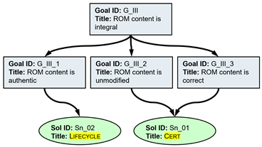
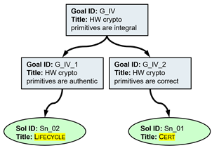
In the following, the integrity of code/data is intended as the combination of three properties:
- Authentic—i.e., its provenance can be verified in terms of identity of the source;
- Unmodified—i.e., the item has not been intercepted and changed while in transfer/use;
- Correct—i.e., code/data complies with specifications.
Six recurring arguments have been identified:
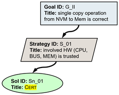
- I.
- A single copy operation from NVM to Memory is correct: the hardware involved in the execution of the operation is certified to be reliable (Section 5.1); the copied code/data is not modified by the copy operation.
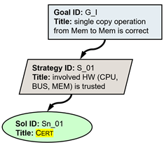
- II.
- A single copy operation from Memory to Memory is correct: the hardware involved in the execution of the operation is certified to be reliable (Section 5.1); the copied code/data is not modified by the copy operation.
- III.
- The ROM content is integral: authenticity is guaranteed by the manufacturing environment (Section 6.4), while absence of modifications after manufacturing, and correctness, are certified (Section 5.1).
- IV.
- The hardware cryptographic primitives are integral: authenticity is guaranteed by the manufacturing environment (Section 6.4), while correctness is certified (Section 5.1). Absence of modifications after manufacturing is implicitly guaranteed by the primitives being implemented in hardware.
- V.
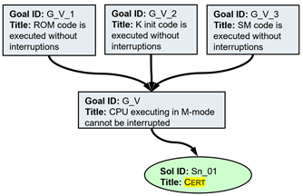
- The execution of platform boot code, Kernel Initialization code, and Security Monitor code cannot be interrupted, including transitions from one macro step to the next: this property is guaranteed by certification (Section 5.1).
- VI.
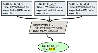
- During the execution of platform boot code, Kernel Initialization code, and Security Monitor code, the involved hardware behaves as per its specification: this property is also guaranteed by certification.
9.4. Trusted Boot Argument
The main goal of the argument shown in Figure 14 is to provide evidence that the Trusted Boot process, implemented by the Platform Boot Code (PBC) and illustrated in Section 7.1, satisfies the manufacturer’s requirements described by the invariant in Section 9.2.
Figure 14.
Trusted Boot assurance case.
The argument examines the operations performed by the process, and shows that, at the end of it, the requirements are satisfied, despite potential interferences in line with the attacker model presented in Section 5.2.
The reasoning stands on shared arguments from Section 9.3:
- The ROM content, consisting of PBC and public key PK for K_img authentication, is integral, and cannot be compromised by the attacker (III);
- PBC execution cannot be interrupted by the attacker, neither within steps, nor between steps (V);
- The hardware cryptographic primitives are integral, and cannot be compromised by the attacker (IV);
- Copy operations from NVM to Memory and from Memory to Memory are correct, and cannot be tampered with by the attacker (II,I);
- The relevant hardware behaves as expected (VI).
The reasoning follows the Trusted Boot process steps, in order.
- Step 1.
Copy K_bin from NVM to Memory, extract K_img and sgn(H(K_img)) from K_bin.
K_img is correctly copied from NVM to Memory (D).
- Step 2,4.
Extract H(K_img) from sgn(H(K_img)) and compute a new hash H2 of K_img, using hardware cryptographic primitives and PK stored in the ROM. Check hash consistency: if H(K_img) is equal to H2, then jump to K_init_code, otherwise halt CPU.
Authentication of K_img succeeds if and only if K_img corresponds to the Kernel image provisioned by the manufacturer. In fact:
- PK is integral (A);
- Its corresponding private key is confidential, and cannot be disclosed to the attacker (Section 6.4);
- The cryptographic primitives that use PK and private key for authentication are integral (C).
- Then, in step 4, Trusted Boot fails and CPU halts if authentication fails; Trusted Boot succeeds and starts Kernel Initialization if authentication succeeds.
- Step 3.
Reorganize Memory content:
- 1.
- Create a Kernel Memory region partitioned into a sub-region hosting code (K_Code) and a sub-region hosting data (K_Data);
- 2.
- Copy K_init_code and SM_code into K_Code;
- 3.
- Copy SM_config and Apps_config into K_Data.
The reorganization operations preserve data and code integrity and comply with the intended Memory layout: the code responsible for reorganization is integral (A), and copy operations are correct (D).
Summarizing, the Trusted Boot process runs without interferences, and, at the end, Kernel Initialization starts if and only if code in K_init_code, SM_code, and data in SM_config, Apps_config, are integral in Memory and comply with the layout, consistently with the invariant in Section 9.2.
9.5. Kernel Initialization Argument
The main goal of the argument shown in Figure 15 is to provide evidence that the Kernel Initialization process, implemented by K_init_code in Memory, and illustrated in Section 7.2, satisfies the manufacturer’s requirements in Section 4 and the invariant in Section 9.2.
Figure 15.
Kernel Initialization assurance case.
The argument examines the operations performed by the process, and shows that, at the end of it, the requirements are satisfied, despite potential interferences in line with the attacker model presented in Section 5.2.
The reasoning stands on shared arguments from Section 9.3:
- Kernel Initialization execution cannot be interrupted by the attacker, neither within steps, nor between steps (V);
- The hardware cryptographic primitives are integral, and cannot be compromised by the attacker (IV);
- Copy operations from NVM to Memory and from Memory to Memory are correct, and cannot be tampered with by the attacker (I,II);
- The relevant hardware behaves as expected (VI).
- On the properties argued to hold at the end of the Trusted Boot process, K_init_code, SM_code, SM_config, Apps_config are integral.
The reasoning follows the Kernel Initialization process steps, in order.
- Step 1.
A data structure (K_M_Layout) is created, that describes the layout of the Kernel Memory region; it contains:
- Start address and size of K_Code and K_Data, and of their content, as loaded at the Trusted Boot step;
- Start address and size of K_Imm_Data, a sub-region to host data that is expected not to change after the Kernel Initialization process completion; immutability relies on Kernel and Apps’ Memory access control policies, as discussed in this section;
- Start address and size of the other Kernel sub-regions that are introduced in this section.
K_M_Layout is correct. It is created by the uninterrupted execution of K_init_code, based on SM_config loaded in Memory; both K_init_code and SM_config are integral.
- Step 2.
A data structure (App_Auth_Keys) is created within K_Data, based on Apps_config, to host public keys App_PK for the digital signature verification of the Apps that require authentication.
App_Auth_Keys is correct. It is created by the uninterrupted execution of K_init_code, based on Apps_config loaded in Memory; both K_init_code and Apps_config are integral.
- Step 3.
Another data structure (App Memory Access Control Policy, or AMACP) is created within K_Imm_Data, based on Apps_config; it is a list of structures, one per App, with the following fields:
- App identifier (App_ID).
- Start address and size of the App code (Code_Addr, Code_Size).
- Start address and size of the App data (Data_Addr, Data_Size).
- Entities allowed for shared Memory-based communication, based on Com_Policy, each represented by a structure with fields:
- –
- Entity identifier, let it be an App or a Peripheral (E_ID);
- –
- Start address and size of the App shared Memory region (Sh_Addr, Sh_Size);
- –
- Communication model, as per Apps_Config (Com_Model).
- Note that Com_Policy only contains information for an App to establish communication with other Apps. Shared regions for communicating with Peripherals are determined as part of the Memory layout definition, while Com_Model grants R+W rights both to App and SM, responsible for executing the Peripherals drivers.
AMACP is correct w.r.t. the System Security Policy and Com Policy of Section 9.2: AMACP is created by the uninterrupted execution of K_init_code, based on Apps_config in Memory. K_init_code and Apps_config are integral.
- Step 4.
Each App is loaded into Memory, by: (i) copying App_bin from NVM to Memory, (ii) executing digital signature verification, if required by the Auth_bit, and (iii) reorganizing the App content according to AMACP. Apps digital signature verification consists of the following two steps:
- Extract A_img and sgn(H(A_img)) from App_bin;
- Extract H(A_img) from sgn(H(A_img)) and compute a new hash H2 of A_img, using hardware cryptographic primitives and App_PK stored in the App_Auth_Keys data structure.
- If signature verification fails, then the App is marked in the AMACP as having failed authentication.
Apps binaries are correctly copied from NVM to Memory (C).
Apps are correctly authenticated. In fact, K_init_code is executed without interruptions:
- Authentication by means of digital signature verification occurs if and only if an App is identified as authentic by the Auth_bit in Apps_config (K_init_code and Apps_config are integral).
- Digital verification of an A_img marked authentic succeeds if and only if A_img corresponds to the App image provisioned by the manufacturer. In fact:
- –
- App_PK is integral, as per step 2 and Apps_config integrity;
- –
- Its corresponding private key is confidential, and cannot be disclosed to the attacker; this is guaranteed by the manufacturing environment (Section 6.4);
- –
- The cryptographic primitives that use App_PK and private key for authentication are integral (B).
- An App is marked in the AMACP as having failed authentication if and only if digital verification fails (K_init_code is integral); correctness of the AMACP is then preserved by this update. Apps’ content reorganization preserves data and code integrity and comply with the intended Memory layout, due to K_init_code integrity, AMACP correctness (step 3), and copy operations correctness (C).
- Step 5.
The drivers P_D of each Peripheral occurring in Apps_config are copied into K_Code. For each Peripheral, registers are Memory-mapped and represented in a P_Config data structure created within K_Data, by defining start address and size of a corresponding MM_P region.
All and only the drivers of Peripherals relevant to Apps, according to Apps_config, are correctly copied from K_img into K_Code: K_init_code is integral, Apps_config is integral, and copy from Memory to Memory is correct (C).
Memory-mapping of the registers is implemented in hardware; the content of P_Config is correct, due to K_init_code integrity.
- Step 6.
The Kernel Memory access control policy (KMACP) is implemented at the MPU level, consistently with K_M_Layout and AMACP, by configuring MPU_CR and setting the locked bit to prevent further modifications. The MPU_CR rules are summarized as follows:
- 1.
- Kernel can access K_Code in X mode;
- 2.
- Kernel can access K_Data in R+W mode;
- 3.
- Kernel can access K_Imm_Data in R mode;
- 4.
- For every App A in AMACP and Peripheral P assigned to A, Kernel can access A_P_Share in R+W mode;
- 5.
- Kernel cannot access Apps Memory regions.
KMACP MPU_CR entries correctly define Kernel Memory regions and access control. In fact:
- K_M_Layout is correct, as per step 1;
- AMACP is correct, as per step 3;
- MPU_CR entries are correctly set and locked: K_init_code is integral and executes based on correct information.
Summarizing, the Kernel Initialization process runs without interference, and, at the end, Security Monitor execution starts if and only if:
- K_M_Layout is integral;
- AMACP is correct and unmodifiable, since in K_Imm_Data;
- Apps are correctly loaded and authenticated: only Apps that are identified as authentic, and have been successfully authenticated, and Apps that are not identified as authentic, are executable;
- Peripherals drivers are correctly loaded, P_Config is correct, and registers are correctly Memory-mapped;
- KMACP is correct and unmodifiable, due to the locked bit being set.
- This is consistent with the invariant in Section 9.2.
Moreover, the execution of K_init_code does not compromise the integrity of SM_code, SM_config, Apps_config, and K_init_code itself, which is then maintained through the Kernel Initialization process.
9.6. Security Monitor Execution Argument
The main goal of the argument shown in Figure 16 is to provide evidence that the Security Monitor execution process, implemented by SM_code in Memory and illustrated in Section 7.3, satisfies the manufacturer’s requirements described by the invariant in Section 9.2.
Figure 16.
Security monitor assurance case.
The argument examines the behavior of the Security Monitor in an execution cycle, and in the three scenarios of shared Memory-based communication, across multiple cycles; the argument shows that, at the end of an SM turn, the requirements are satisfied, despite potential interferences in line with the attacker model presented in Section 5.2.
The reasoning stands on shared arguments from Section 9.3:
- Security Monitor execution cannot be interrupted by the attacker, neither within steps, nor between steps (V);
- The relevant hardware behaves as expected (VI).
- On the property argued to hold at the end of the Kernel Initialization process, and at the beginning of each SM turn: K_M_Layout is correct, AMACP and KMACP are correct (the latter unmodifiable), Apps and Peripherals drivers are correctly loaded; moreover, SM_code, SM_config, Apps_config are still integral after Kernel Initialization.
The reasoning is more complex than in the cases of Trusted Boot and Kernel Initialization, since it is not sufficient to consider a single sequence of steps, and the Security Monitor itself includes multiple components with different responsibilities. The top-level goal depends on four high-level goals:
- 1.
- The Security Monitor executes in compliance with System Security Policy (SSP) and Com Policy (CP);
- 2.
- The Security Monitor preserves both confidentiality and integrity of Apps, according to SSP and CP;
- 3.
- The Partition Manager component of the Security Monitor sets MPU_CR entries related to Apps Memory regions as per SSP and CP, before context switching to App execution;
- 4.
- No other Security Monitor component sets MPU_CR entries related to Apps Memory regions.
- Each of these goals will be examined in one of the following subsections.
- Sub-Goal 1: The Security Monitor executes in compliance with SSP and CP.
Sub-goal 1 is shown in Figure 17. On one side, the MPU Configuration Register entries defining the KMACP cannot be modified to induce the Kernel to cause a violation of the policies. First, the entries set during the Kernel Initialization process are locked and unmodifiable, as described in Section 9.5 step 6. Second, any entry potentially set by an attacker after Kernel Initialization cannot override existing entries: Kernel and Apps’ code and data regions are covered by KMACP, there are no gaps between entries, and entries are evaluated in order, first to last added.
Figure 17.
Security monitor assurance case, Sub-goal 1.
On the other side, it is not feasible to exploit SM vulnerabilities at run-time, leading to a violation of SSP or CP; in fact, each of the three SM components is compliant with the policies. The Partition Manager and the Support Services are respectively discussed in Sub-goals 1.1 and 1.2. The Scheduler, responsible for choosing which App to run each time, cannot be induced to access other Memory areas than those determined by its code; as for these areas, they do not include Apps regions, AMACP, or Apps notification registry. The Scheduler does not modify any MPU_CR entry and is protected from potentially hostile behaviors of Peripherals drivers.
- Sub-Goal 1.1: The Partition Manager accesses Memory in compliance with SSP and CP.
Sub-goal 1.1 is shown in Figure 18. The Partition Manager is responsible for saving and loading Apps state, and for setting MPU_CR entries. An attacker might try to induce the PM to cause a violation of the policies either (i) on the Kernel side, or (ii) on the Apps side.
Figure 18.
Security monitor assurance case, Sub-goal 1.1.
(i) On the Kernel side, the PM is constrained to access Apps Memory regions exclusively for the sake of saving and loading their state; moreover, the AMACP, according to which MPU_CR entries are set, has been made unmodifiable after the Kernel Initialization process.
(ii) On the Apps side, the PM correctly saves and loads Apps states. Apps SSP and CP are correctly implemented by setting and setting to zero MPU_CR entries based on AMACP, and temporary data structures are properly, created, deleted, and accessed during App-to-App managed communications.
- Sub-Goal 1.2: The Support Services (including Peripherals drivers) access Memory in compliance with SSP and CP.
Sub-goal 1.2 is shown in Figure 19. The Support Services address system calls, particularly those related to communication activities or Peripherals operations. An attacker might try to induce the SR to cause a violation of the policies either (i) on the Kernel side, or (ii) on the Apps side.
Figure 19.
Security monitor assurance case, Sub-goal 1.2.
(i) On the Kernel side, the SR are constrained to execute a Peripherals drivers, during App-to-Peripheral managed communication, having access only to Memory-mapped MM_P and shared A_P_Share regions, according to AMACP, which is not modifiable.
(ii) On the Apps side, SR activities do not have any impact on the MPU_CR entries.
- Sub-Goal 2: The Security Monitor preserves integrity and confidentiality of Apps in compliance with SSP and CP.
Sub-goal 2 is shown in Figure 20. The argument relies on three sub-arguments, one for each of the three SM components.
Figure 20.
Security monitor assurance case, Sub-goal 2.
The Partition Manager, as discussed in Sub-goal 1.1, only accesses Apps Memory regions for saving and loading their state. States are temporarily stored in a dedicated data structure in K_Data, the access to which is enforced by KMACP since the Kernel Initialization process. While loading or saving, the PM does not disclose any information about the Apps state to other entities.
The Scheduler, as argued in Sub-goal 1, cannot be induced to access other Memory areas than those determined by its code, which do not relate to Apps regions.
- Sub-Goal 2.1: The Support Services preserve integrity and confidentiality of Apps in compliance with SSP and CP.
Sub-goal 2.1 is shown in Figure 21. An attacker might try to induce the SR to compromise integrity and confidentiality either (i) on the Kernel side, or (ii) on the Apps side. The same reasoning as in Sub-goal 1.2 applies here.
Figure 21.
Security monitor assurance case, Sub-goal 2.1.
(i) On the Kernel side, the SR are constrained to execute Peripherals drivers, during App-to-Peripheral managed communication, having access only to Memory-mapped MM_P and shared A_P_Share regions, according to AMACP, which is not modifiable.
(ii) On the Apps side, the SR activities do not have any impact on the MPU_CR entries.
- Sub-Goal 3: The Partition Manager component of the Security Monitor sets MPU_CR entries related to Apps Memory regions as per SSP and CP, before context switching to App execution.
Sub-goal 3 is shown in Figure 22. Recalling that the PM is the only component authorized to update the MPU_CR (see next Sub-Goal), an attacker could either (i) compromise the sources of information, based on which the content of the MPU_CR is determined, or (ii) tamper with the functions that actually set the entries.
Figure 22.
Security monitor assurance case, Sub-goal 3.
In the first case, it is sufficient to remark that AMACP is unmodifiable, since in K_Imm_Data, and that the KMACP entries in the MPU_CR are unmodifiable, due to the locked bit.
In the second case, AMACP information is correctly employed to set and set to zero MPU_CR entries as per policies. During App-to-App managed communications, temporary data structures are properly created, deleted, and accessed according to CP.
- Sub-Goal 4.
Sub-goal 4 is shown in Figure 23. Certification guarantees and software-based methods ensure that, in the Security Monitor, only the Partition Manager can make modifications to the entries of the MPU_CR.
Figure 23.
Security monitor assurance case, Sub-goal 4.
- Peripherals.
The goals related to Peripherals are shown in Figure 24. Software mechanisms are put in place to ensure that Security Monitor code and data are protected from unexpected behaviors during Peripheral drivers’ code execution by the Support Services; Memory safety is then guaranteed for PM, SC, and SR.
Figure 24.
Security monitor assurance case, Peripherals.
10. Conclusions
In this section, we summarize the results reported in the current paper and possible next steps.
Our research explored approaches for documenting security architectures, related design decisions, and how they contribute in establishing desired security requirements. The adoption of (a subset of) GSN notation has been motivated by the need of a rigorous approach while not going to the extreme of a formal language and consequential complexity. The proposed approach has the objective to be usable and scalable while adhering to a syntax and guidelines that should support improved coverage of all design aspects, better accuracy, and consistency. Further support in this direction has been provided by extending the GSN notation with the notion of attacker action, which has the intent of considering multiple scenarios where the attacker can compromise the achievement of the topmost goal and how the design is able to cover those scenarios. The validation activity successfully relied upon modularization and reuse of GSN arguments, with arguments covering both hardware and software aspects. The high-level security model developed for the validation is based on architectural approaches that are common to many IIoT platforms and therefore amenable to reuse with limited adaptation. Overall, the entire set of assurance objectives has been covered and assurance cases are of limited complexity, allowing their review for auditing and traceability purposes.
A practical consideration is how end users maintain the assurance case during system updates, such as deploying new applications, modifying policies, or adding peripherals. An important next step is how to better link assumptions with related assurance case goals, expanding on considerations shared in Section 5.1. Modifications on trusted, untrusted, and semi-trusted elements have different impact on the assurance case. By focusing on sub-goals, users can update only the affected assurance case branches, thus limiting the effort to the changed components rather than rebuilding the entire assurance case from scratch. Developing robust approaches for traceability and impact analysis, particularly in case of assumption revision, would facilitate long-term maintenance of the assurance case.
There are multiple next steps that can be considered. On one side, the adopted fragment of GSN notation may be amenable to formalization, to increase confidence of the discharging of the upper-level goal based on lower-level goals, as well as to assess consistency of different goals. Another important area where the current work makes strong assumptions is the role of untrusted peripherals. For example, confused-deputy attacks are best mitigated by capability-based security models. This is the approach adopted by seL4 [20], which is however a much more complex design and represents a multi-year/multi-project effort. In contrast, our work focuses on a significantly smaller scope, with the intent of demonstrating a feasible and yet cost-effective method for documenting (at a reasonable level of detail) assurance arguments for highly resource-constrained computing nodes. While our approach leaves certain gaps and unaddressed threats that a more robust design could mitigate, it raises an interesting question: whether the proposed GSN approach would be capable of scaling to greater complexities, with less effort than fully formal modeling and proof methods as in seL4. A partial mitigation for untrusted devices threats is achieved through the ordering and first-match behavior of MPU rule evaluation (discussed in Section 6.1.4); together with the guarantees provided by the the Rust language, this offers partial support to threats mitigation in the assurance argument.
On the other side, considering the methodological aspect, it would be interesting to explore the relation with threat modeling and cyber risk assessments, for example, to identify all possible attacker actions applicable to a specific goal. In this context, for reasons of simplicity and to manage the complexity of the assurance case, the proposed attacker model was intentionally limited to a subset of potential physical attacks. Several threats relevant to the IIoT ecosystem were excluded, but could be considered in an extension of the present work: all the attacks (such as power consumption, electromagnetic, and timing analysis, as well as attacks exploiting speculative execution) leveraging side-channels for obtaining the disclosure of secrets; attacks leveraging microarchitecture design weaknesses to cause interference or control flow modification; attacks relying on hardware faults to bypass or modify the logic in charge of building the chain of trust; attacks to external memories with the intent of bypassing separation enforcement; attacks to communication buses by eavesdropping, spoofing, or tampering messages and leading to impersonation, secrets stealing, or interference; attacks leveraging weak or untrusted peripherals for DMA access or Kernel compromise; attacks leveraging privileged hardware access (e.g., via JTAG) to cause firmware integrity compromise, privilege escalation, and data/code integrity compromise at execution time. On one side, reasoning about these attacks would rely on the same GSN principles and modeling primitives shown in this work. On the other side, though, the interplay between lower hardware layers and upper software mechanisms was proven hard to understand and address also by experts. Therefore, we believe that exploring these specific threats would present interesting challenges in defining the proper abstraction level to express goals and their hardware-software interdependencies.
From the perspective of applicability and usability, it would be interesting to further explore the relation between assurance cases and architecture decomposition, to understand how to leverage parallelisms between the two representations. On the same line, it would be interesting to study how any architectural or design change can be handled and how the GSN notation can help reduce the overall burden of change management. The latter point relates well to certification and it would be important to explore how the GSN-based documentation can be leveraged effectively for earning certification credits. Finally, it would be important to perform a broader exploration of different security properties and how well they are handled in the GSN notation, given the limited exploration of application of GSN to security in the literature.
Existing literature [31,32,33] discusses risks and limitations of adopting GSN for cybersecurity assurance. First, GSN can promote acceptance of “after-the-fact” assurance: constructing an argument around an already designed system, rather than integrating security into the architecture from the beginning. For large and complex systems, underestimation of this risk can make serious design flaws very hard or too expensive to identify, until the argument reveals them, possibly leading to ex-post retrofits or to the acceptance of logically weak arguments. Second, GSN’s graphical style does not inherently enforce logical rigor; studies show that standard GSN lacks the precision to specify exactly how premises support conclusions, capturing the logical relations between nodes, which can result in logically flawed or overconfident security claims. Related research [34] notes that natural-language GSN arguments are prone to ambiguity and require extensive manual review, making them error-prone and difficult to scale. Third, realistic cybersecurity assurance cases (e.g., for IoT or automotive systems) quickly become large, and hidden gaps may result in unsupported claims. Finally, effectively using GSN for security requires specialized expertise in both security engineering and argumentation; without proper skills, assurance cases may be superficially convincing, but misrepresent the actual system design. Being aware of these challenges, our approach keeps the assurance argument sufficiently simple and at a manageable abstraction level. This serves as a basis to document assurance and justify the adequacy of the design. While not being the ultimate solution, it enhances auditing and reviews processes, beyond daily practices in non-critical application domains. Moving to critical application domains, instead, the assurance argument needs to be refined into a formally supported argument, where gaps and inconsistencies can be systematically identified and resolved to achieve the required level of assurance.
Author Contributions
Methodology—V.S.; formalization, application, and validation—F.F., S.F.R. and V.S.; paper writing and review—F.F., S.F.R. and V.S. All authors have read and agreed to the published version of the manuscript.
Funding
This research was funded by the EU through the Horizon research and innovation program CERTIFY (grant agreement no. 101069471) and the Swiss SERI (grant agreements no. 22.00165 and 22.00191). The European Commission’s and Swiss SERI’s support for the production of this publication does not constitute an endorsement of the contents, which reflects the views of the authors only, and neither the Commission nor the Swiss Confederation can be held responsible for any use which may be made of the information contained therein.
Data Availability Statement
The original contributions presented in this study are included in the article. Further inquiries can be directed to the corresponding author.
Conflicts of Interest
Authors Valerio Senni, Simone Fulvio Rollini and Fabio Federici were employed by the company Collins Aerospace.
References
- Matheu, S.; Sebastio, S.; Skarmeta, A.; Orizio, R.; Vasileiadis, S.; Kalos, V.; Müller, K.; Grübl, T.; Mancilla, R.O.; Tuck, S.; et al. Active Security for Connected Device Lifecycle: The CERTIFY Architecture. In Proceedings of the Distributed Computing and Artificial Intelligence, Special Sessions I, 21st International Conference; Mehmood, R., Hernández, G., Praça, I., Wikarek, J., Loukanova, R., Monteiro dos Reis, A., Skarmeta, A., Lombardi, E., Eds.; Springer: Cham, Switzerland, 2025; pp. 301–310. [Google Scholar]
- Sebastio, S.; Matheu, S.; Skarmeta, A.; Orizio, R.; Karras, D.; Schumm, D.; Stiller, B.; Mancilla, R.O.; Giampaolo, F.; Tuck, S.; et al. Cybersecurity Management Throughout the IoT Systems Lifecycle—The CERTIFY Approach. In Proceedings of the Distributed Computing and Artificial Intelligence, Special Sessions I, 21st International Conference; Mehmood, R., Hernández, G., Praça, I., Wikarek, J., Loukanova, R., Monteiro dos Reis, A., Skarmeta, A., Lombardi, E., Eds.; Springer: Cham, Switzerland, 2025; pp. 281–290. [Google Scholar]
- Safety Critical System Club. Goal Structuring Notation (GSN) Community Standard—Version 3. 2021. Available online: https://scsc.uk/gsn-standard (accessed on 19 August 2025).
- Rushby, J. Design and Verification of a Secure Operating System Kernel; Technical Report; SRI International: Menlo Park, CA, USA, 1981. [Google Scholar]
- Kelly, T.; Weaver, R. The Goal Structuring Notation—A safety argument notation. In Proceedings of the 2004 International Conference on Dependable Systems and Networks (DSN’04), Florence, Italy, 28 June–1 July 2004. [Google Scholar]
- Rushby, J. Separation and integration in mils (the mils constitution). In Computer Science Laboratory SRI International; Technical Report SRI-CSL-08-XX; SRI International: Menlo Park, CA, USA, 2008. [Google Scholar]
- Alves-Foss, J.; Oman, P.W.; Taylor, C.; Harrison, W.S. The MILS architecture for high-assurance embedded systems. Int. J. Embed. Syst. 2006, 2, 239–247. [Google Scholar] [CrossRef] [Scilit]
- Information Assurance Directorate. U.S. Government Protection Profile for Separation Kernels in Environments Requiring High Robustness. 2007. Available online: https://www.commoncriteriaportal.org/files/ppfiles/pp_skpp_hr_v1.03.pdf (accessed on 19 August 2025).
- Zhao, Y.; Sanán, D.; Zhang, F.; Liu, Y. High-assurance separation kernels: A survey on formal methods. arXiv 2017, arXiv:1701.01535. [Google Scholar] [CrossRef] [Scilit]
- Greve, D.; Wilding, M.; Vanfleet, W.M. A separation kernel formal security policy. In Proceedings of the Fourth International Workshop on the ACL2 Theorem Prover and Its Applications, Boulder, CO, USA, 13–14 July 2003. [Google Scholar]
- d’Amato, F.; Massacci, F. A GSN pattern for security in service-oriented architectures based on MILS. In Proceedings of the 2010 ACM Workshop on Assurable and Usable Security Configuration, Chicago, IL, USA, 4 October 2010; pp. 45–48. [Google Scholar]
- DeLong, R.; Rudina, E. MILS Architectural Approach to Trustworthy IIoT Systems; Technical Report; IIC—Industry IIoT Consortium: Boston, MA, USA, 2021. [Google Scholar] [CrossRef]
- Hawkins, R.; Kelly, T.; Habli, I. Developing Assurance Cases for D-MILS Systems. In Proceedings of the International Workshop on MILS: Architecture and Assurance for Secure Systems, Amsterdam, The Netherlands, 19–21 January 2015. [Google Scholar]
- Ledge, D.J.; Atkey, R. Assurance of security properties of a separation kernel using GSN. In Proceedings of the 1st International Workshop on Assurance Cases for Software-Intensive Systems, San Francisco, CA, USA, 19 May 2013; pp. 33–38. [Google Scholar]
- Hanebutte, N.; Lescher, C. Building a safety case for a separation kernel according to Common Criteria and DO-178B. In Proceedings of the Computer Safety, Reliability, and Security, Naples, Italy, 19–21 September 2011; pp. 146–159. [Google Scholar]
- Goodenough, J.B.; Weinstock, C.B.; Klein, A.Z. Toward a Practice of Assurance Case Development; Technical Report; Software Engineering Institute—Carnegie Mellon University: Pittsburgh, PA, USA, 2013. [Google Scholar]
- Hawkins, R.; Kelly, T.; Gorski, J. Arguing Security: Creating Security Assurance Cases; Lulu. Com: Durham, NC, USA, 2013. [Google Scholar]
- Bloomfield, R.; Khlaaf, H. Confidence argument patterns for security cases. In Proceedings of the 2017 5th International Conference on Reliability, Infocom Technologies and Optimization (Trends and Future Directions) (ICRITO), Dubai, United Arab Emirates, 18–20 December 2017; pp. 568–575. [Google Scholar]
- Denney, E.; Pai, G. Tool-supported assurance cases for software. Innov. Syst. Softw. Eng. 2018, 14, 197–207. [Google Scholar]
- Klein, G.; Elphinstone, K.; Heiser, G.; Andronick, J.; Cock, D.; Derrin, P.; Elkaduwe, D.; Engelhardt, K.; Kolanski, R.; Norrish, M.; et al. seL4: Formal verification of an OS kernel. In Proceedings of the ACM SIGOPS 22nd Symposium on Operating Systems Principles, Big Sky, MT, USA, 11–14 October 2009; pp. 207–220. [Google Scholar]
- Cofer, D.; Gacek, A.; Whalen, M.W. Compositional analysis of system-on-chip security properties. In Proceedings of the 2013 18th IEEE International Conference on Engineering of Complex Computer Systems, Singapore, 17–19 July 2013; pp. 100–109. [Google Scholar]
- Myreen, M.O.; Gordon, M.J. Verified separation kernels: A formal basis for security assurance cases. In Proceedings of the 2010 23rd IEEE Computer Security Foundations Symposium, Edinburgh, UK, 17–19 July 2010; pp. 238–250. [Google Scholar]
- Pinto, S.; Santos, N. Demystifying arm trustzone: A comprehensive survey. ACM Comput. Surv. (CSUR) 2019, 51, 1–36. [Google Scholar] [CrossRef] [Scilit]
- Levy, A.; Campbell, B.; Ghena, B.; Gummadi, P.; Dutta, P.; Levis, P. The tock operating system for low-memory, low-power devices. In Proceedings of the 26th Symposium on Operating Systems Principles, Shanghai, China, 28–31 October 2017; pp. 241–254. [Google Scholar]
- Tock Embedded Operating System. Available online: https://tockos.org/ (accessed on 19 August 2025).
- Jung, R.; Jourdan, J.H.; Krebbers, R.; Dreyer, D. Safe systems programming in Rust. Commun. ACM 2021, 64, 144–152. [Google Scholar] [CrossRef] [Scilit]
- Sabt, M.; Achemlal, M.; Bouabdallah, A. Trusted execution environment: What it is, and what it is not. In Proceedings of the 2015 IEEE Trustcom/BigDataSE/Ispa, Helsinki, Finland, 20–22 August 2015; Volume 1, pp. 57–64. [Google Scholar]
- Waterman, A.; Asanovic, K.; Hauser, J.; Division, C. Risc-V Instruction Set Manual—Volume II: Privileged Architecture. 2025. Available online: https://lf-riscv.atlassian.net/wiki/spaces/HOME/pages/16154769/RISC-V+Technical+Specifications (accessed on 19 August 2025).
- AdaCore. ED-203A/DO-356A Airworthiness Security Methods and Considerations. 2021. Available online: https://www.adacore.com/papers/guidelines-and-considerations-around-ed-203a-do-356a-security-refutation-objectives (accessed on 19 August 2025).
- Weinstock, C.B.; Lipson, H.F.; Goodenough, J. Arguing Security-Creating Security Assurance Cases; Technical Report; Software Engineering Institute—Carnegie Mellon University: Pittsburgh, PA, USA, 2007. [Google Scholar]
- Leveson, N. White Paper on Limitations of Safety Assurance and Goal Structuring; GSN—The Goal Structuring Notation; Springer Nature: Berlin/Heidelberg, Germany, 2020; Available online: http://sunnyday.mit.edu/safety-assurance.pdf (accessed on 19 August 2025).
- Janisar, A.A.; Kalid, K.S.; Sarlan, A.; Gilal, A.R.; Iqbal, M.A.; Khan, M.A. A Security Assurance Case for IoT Systems Using Goal Structure Notation. J. Inf. Technol. Manag. (JISTM) 2025, 10, 381–395. [Google Scholar] [CrossRef] [Scilit]
- Meng, B.; Paul, S.; Moitra, A.; Siu, K.; Durling, M. Automating the Assembly of Security Assurance Case Fragments. In Proceedings of the Computer Safety, Reliability, and Security; Habli, I., Sujan, M., Bitsch, F., Eds.; Springer: Cham, Switzerland, 2021; pp. 101–114. [Google Scholar]
- Cârlan, C.; Ratiu, D. FASTEN.Safe: A Model-Driven Engineering Tool to Experiment with Checkable Assurance Cases. In Proceedings of the Computer Safety, Reliability, and Security; Casimiro, A., Ortmeier, F., Bitsch, F., Ferreira, P., Eds.; Springer: Cham, Switzerland, 2020; pp. 298–306. [Google Scholar]
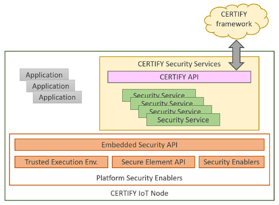
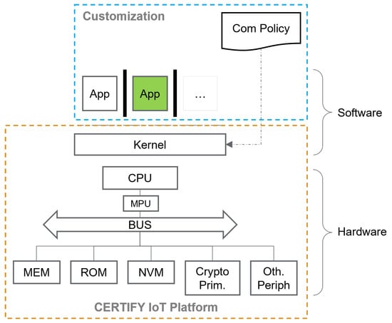
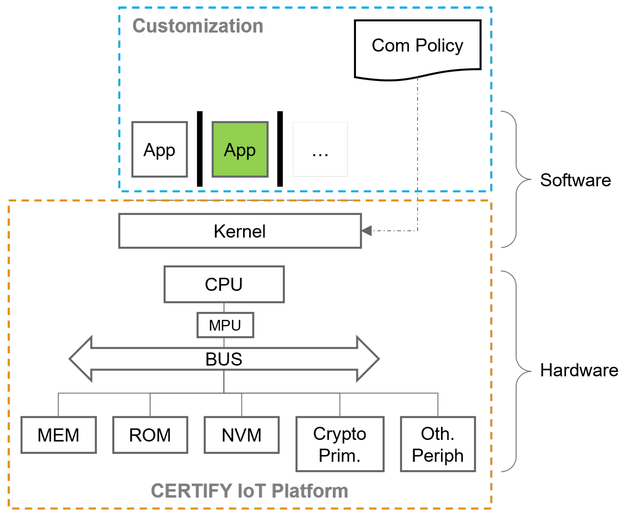
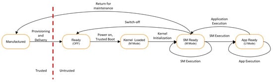
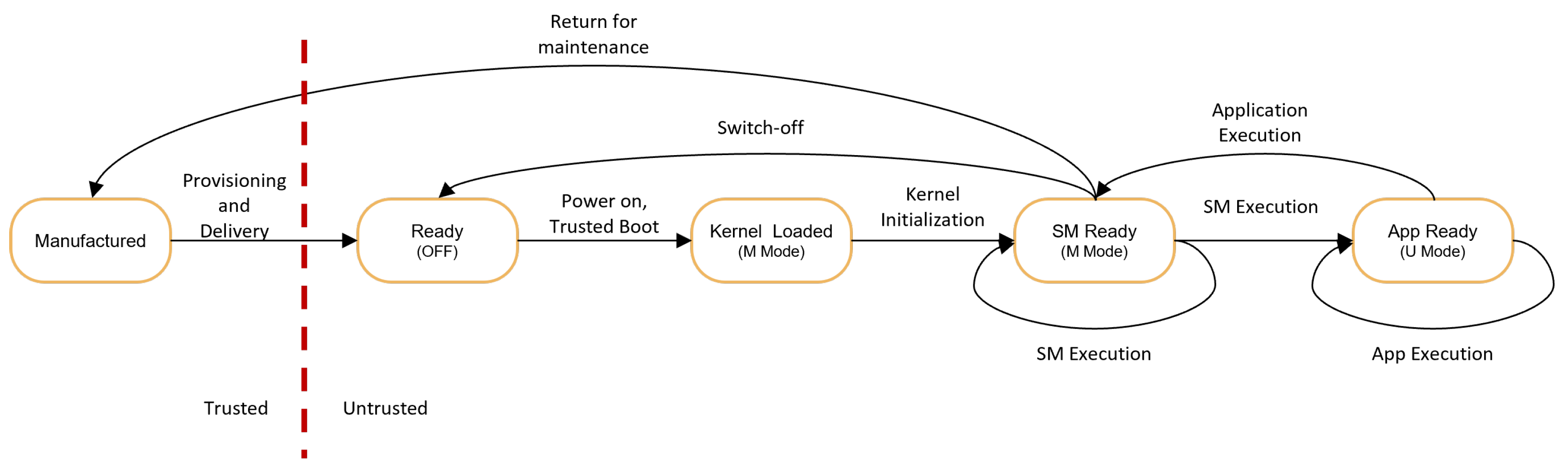
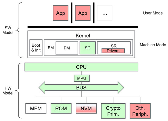
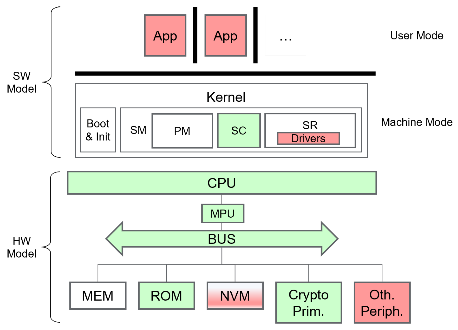
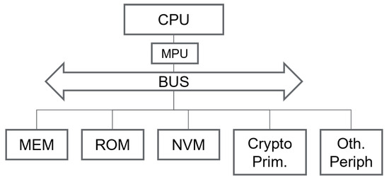
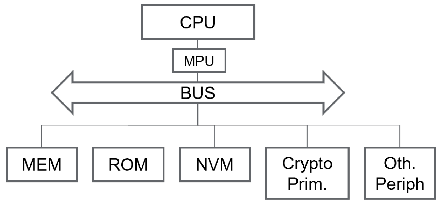
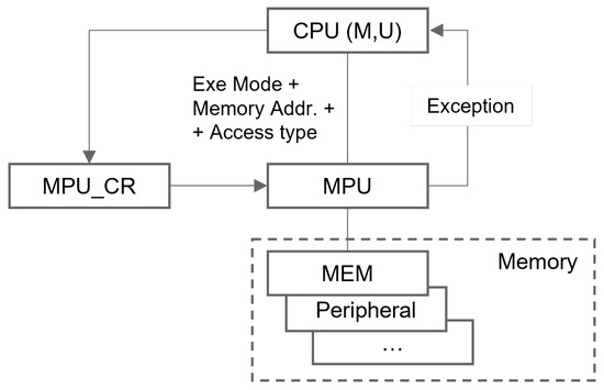
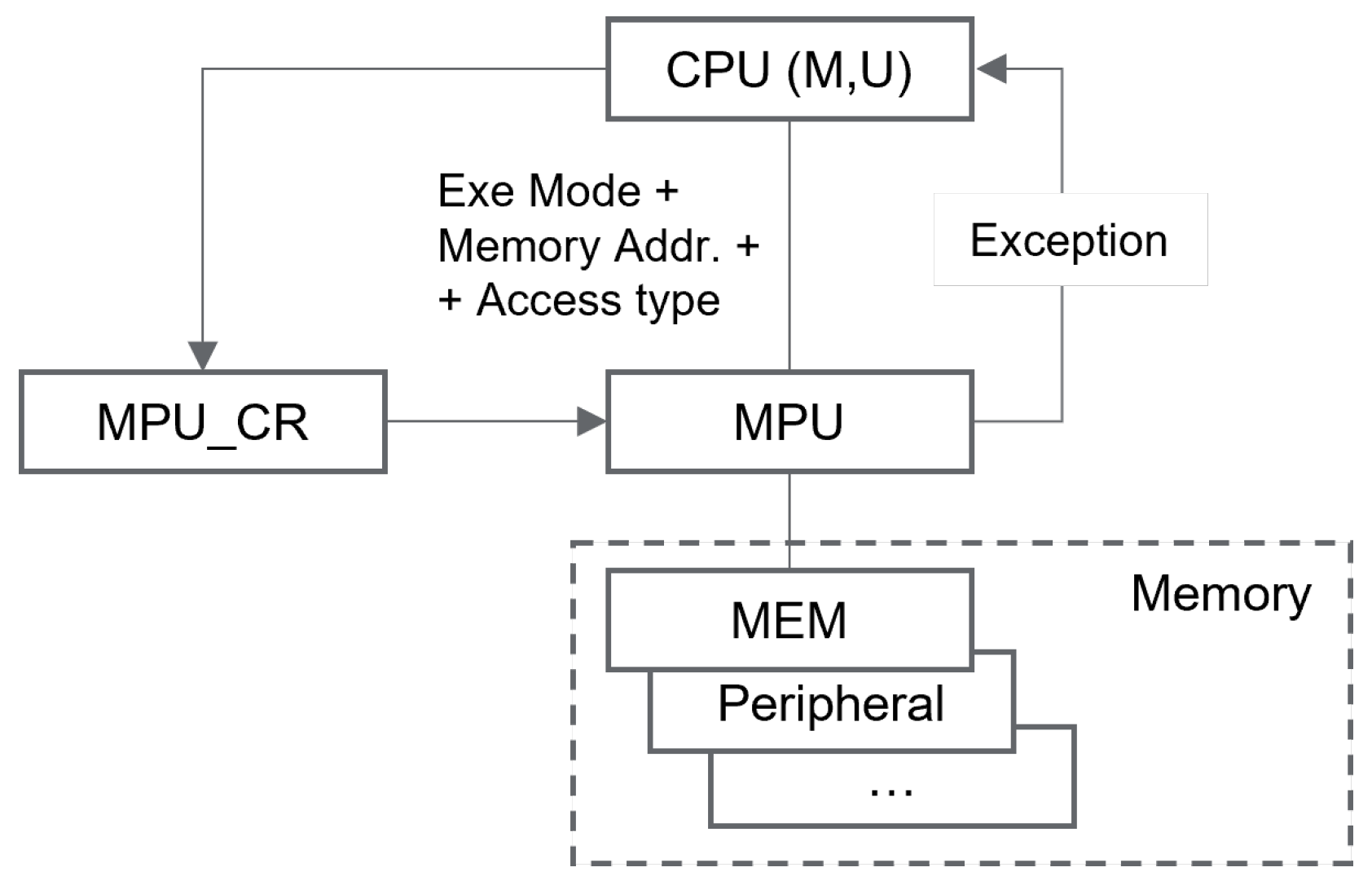
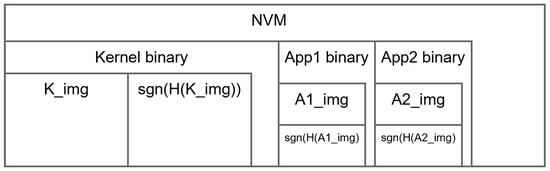
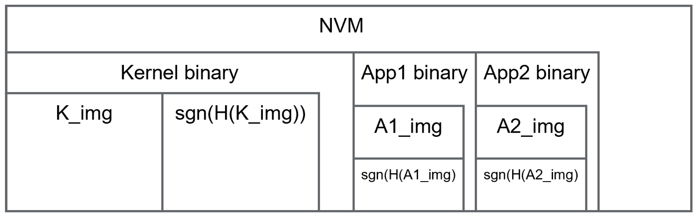
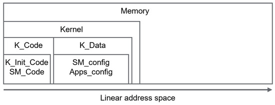
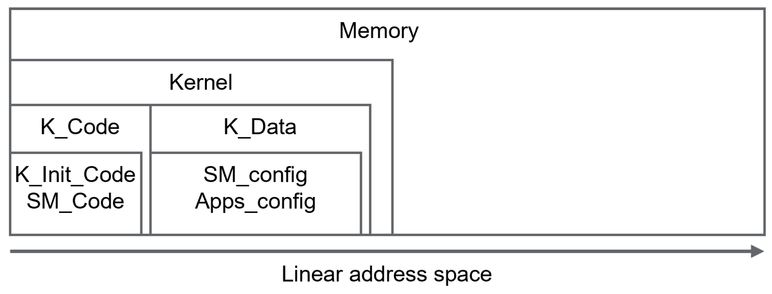
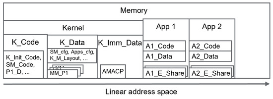
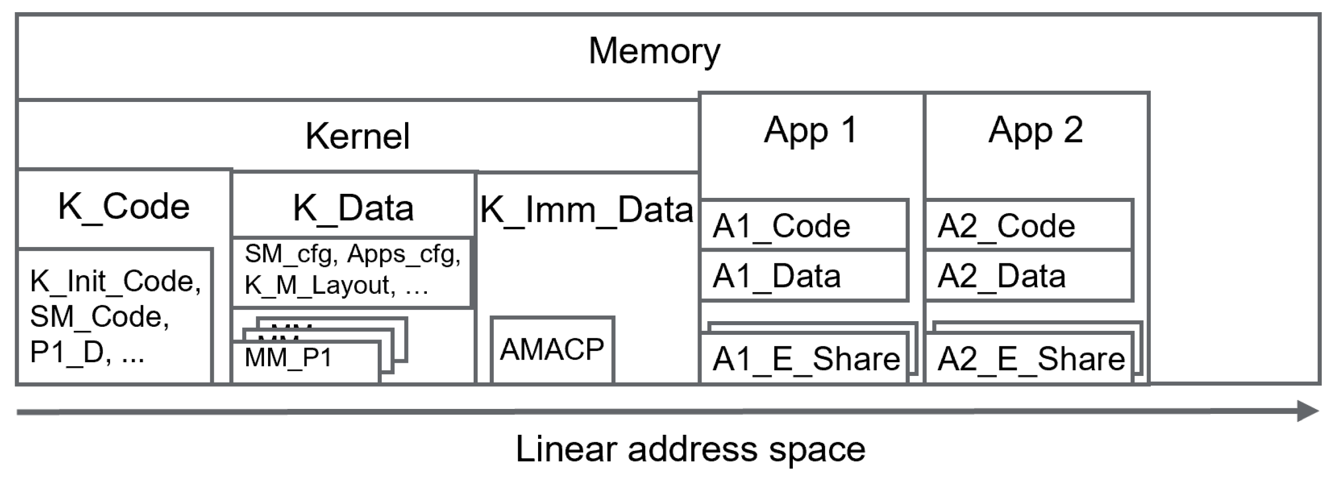


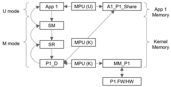
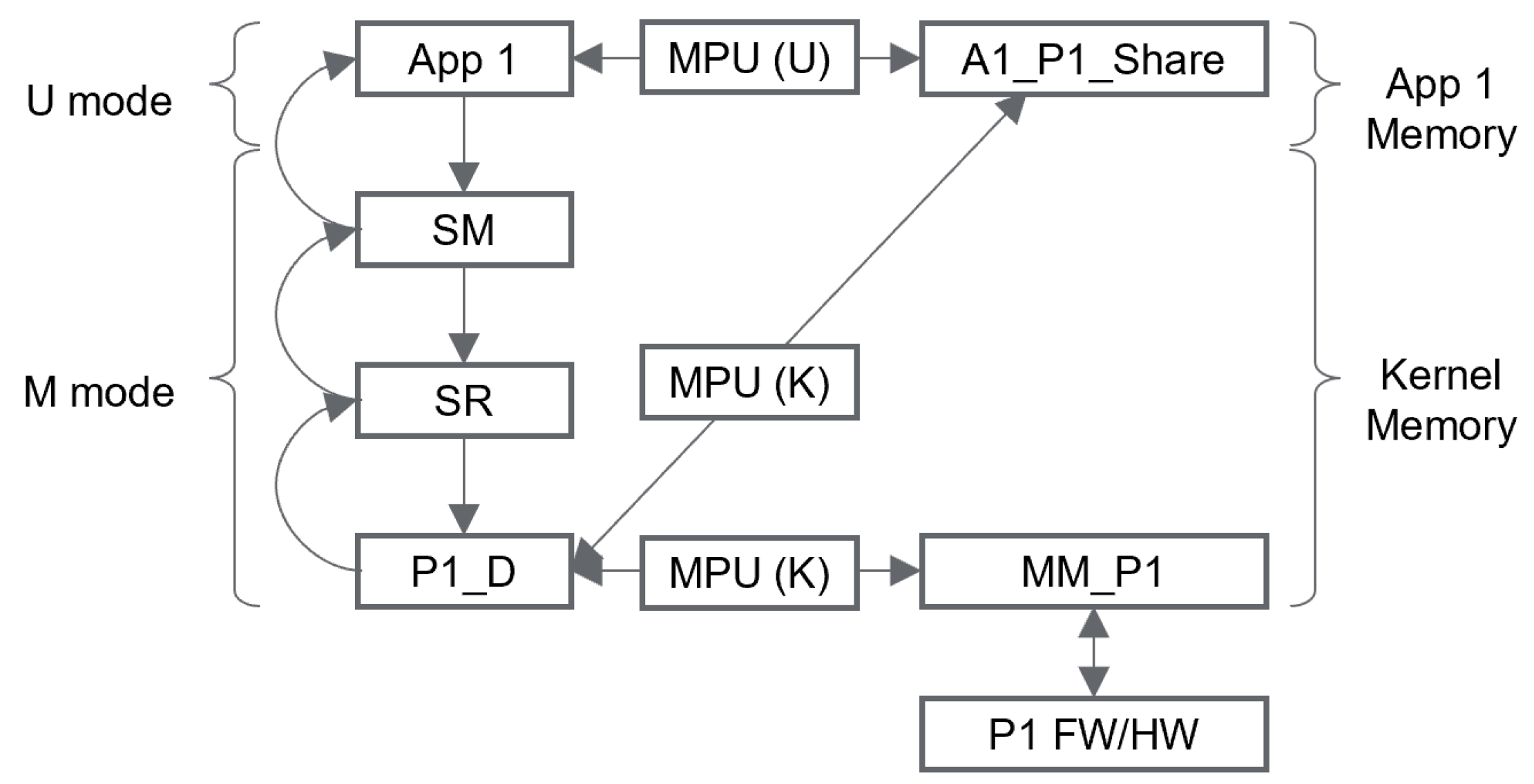
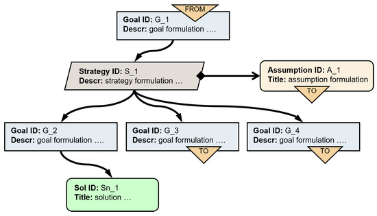
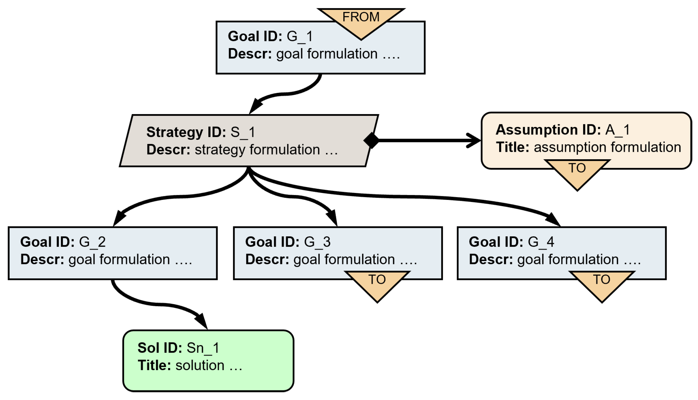
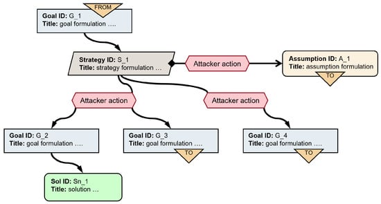
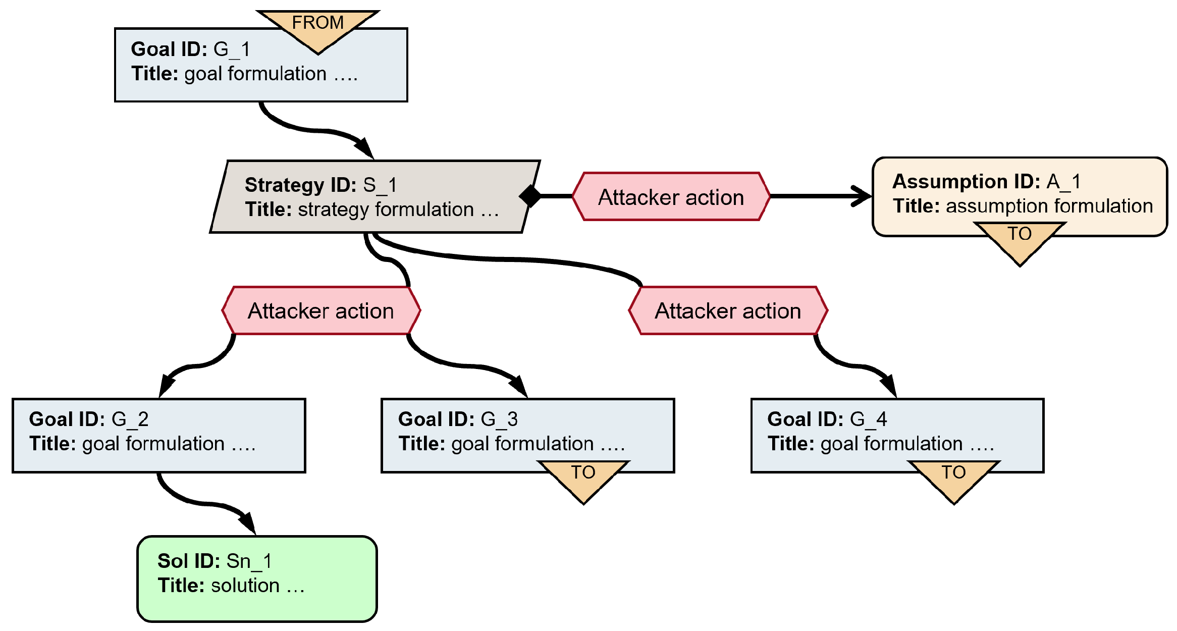
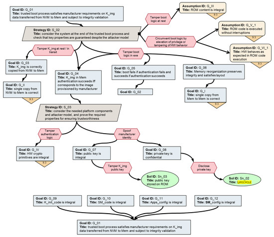
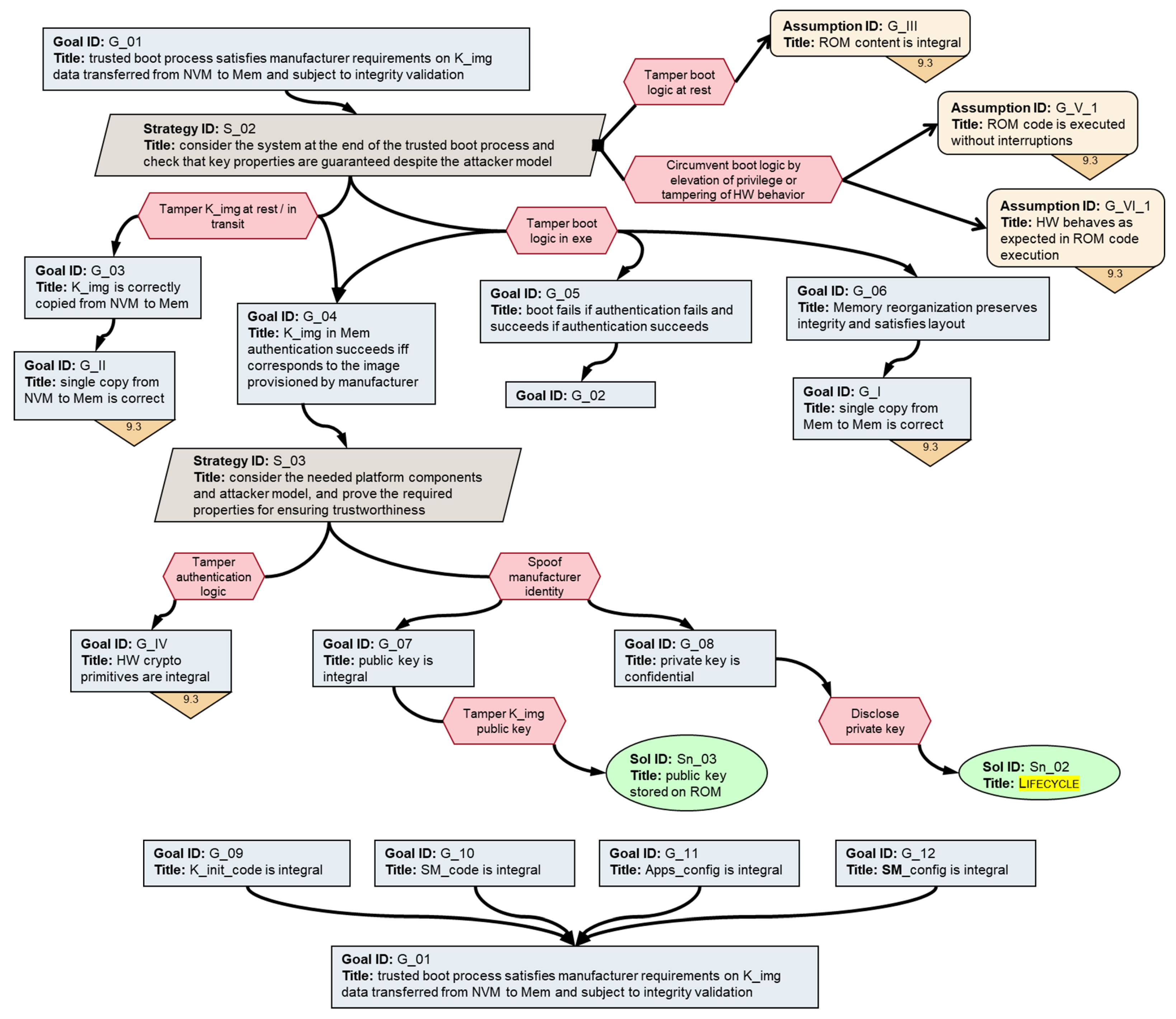
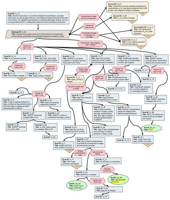
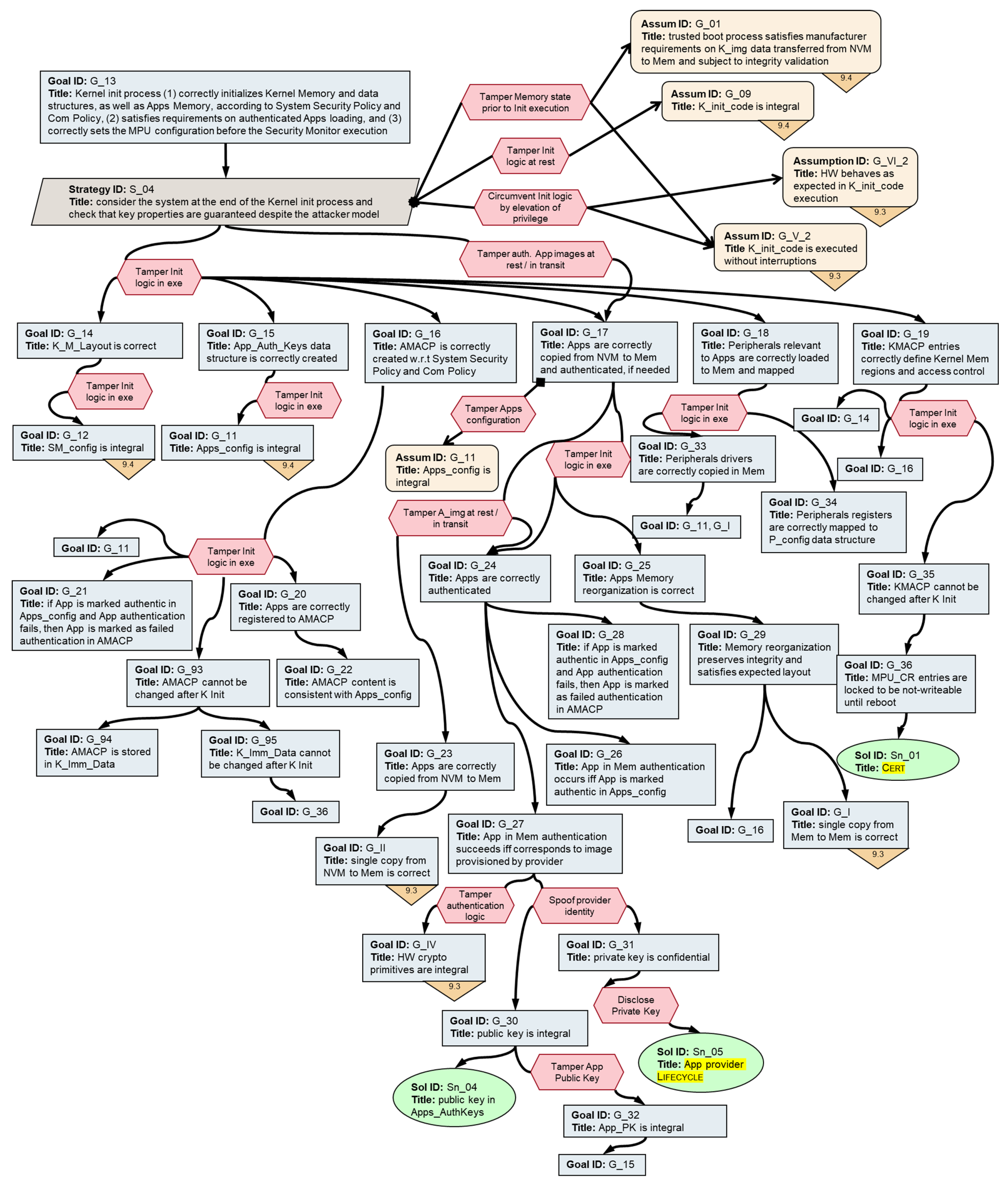
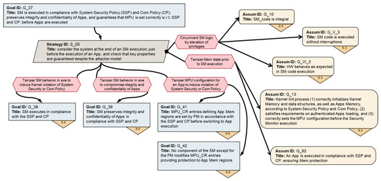
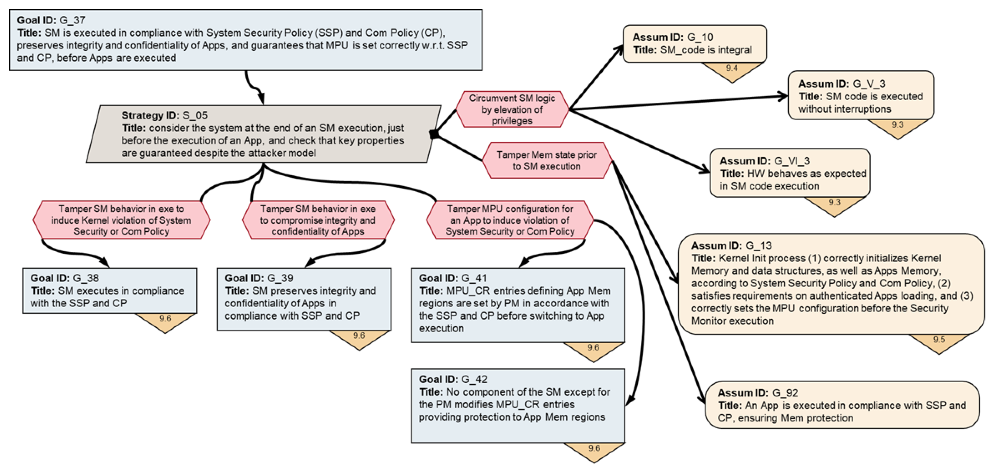
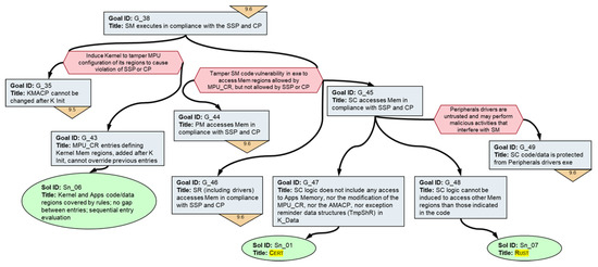
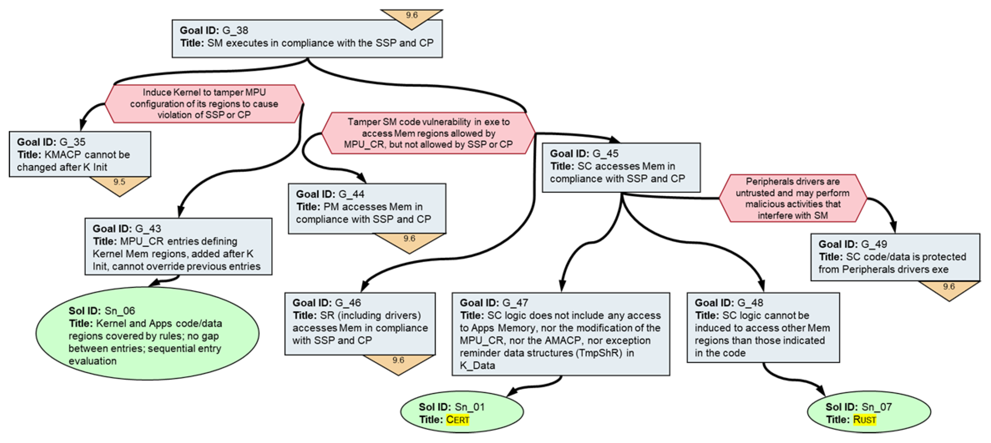
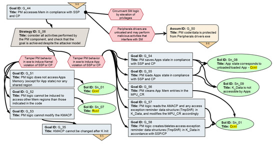
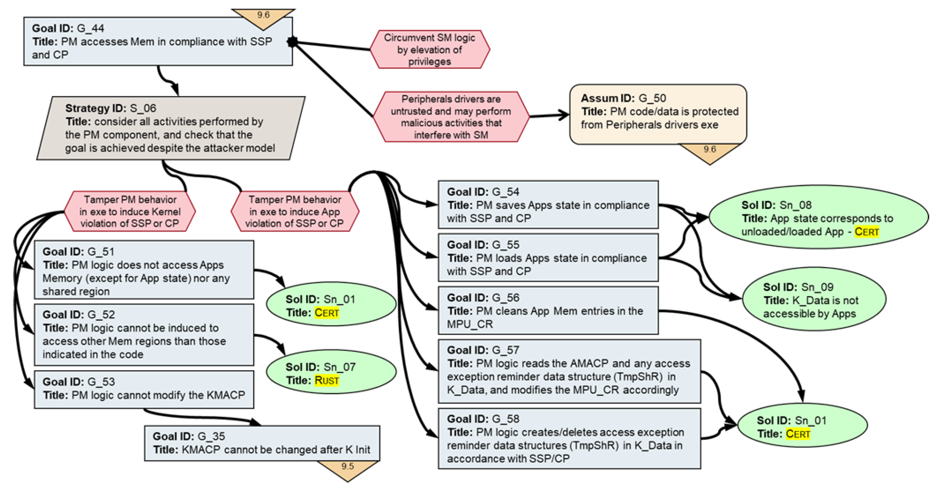
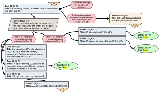
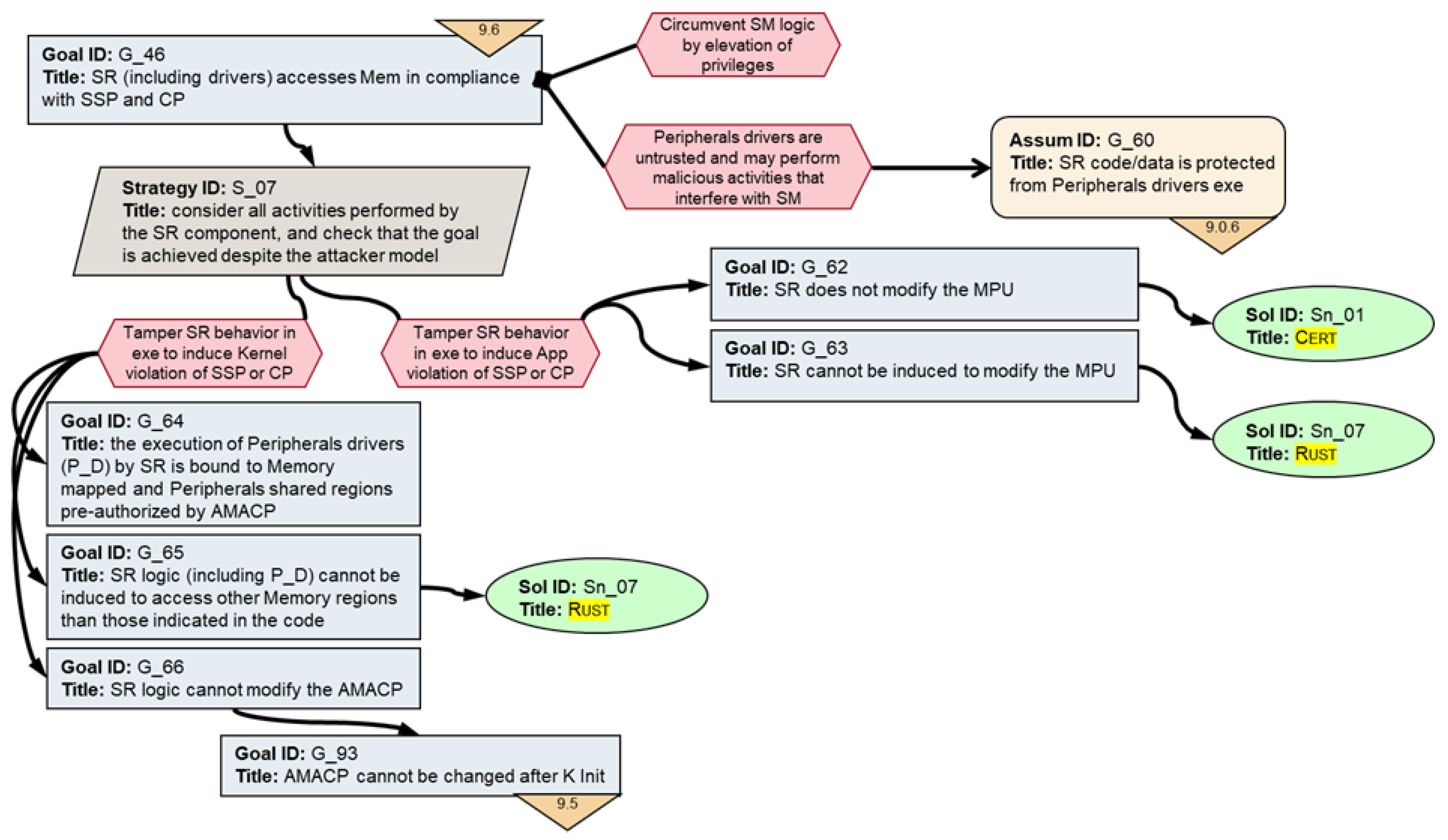
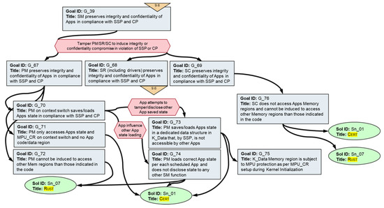
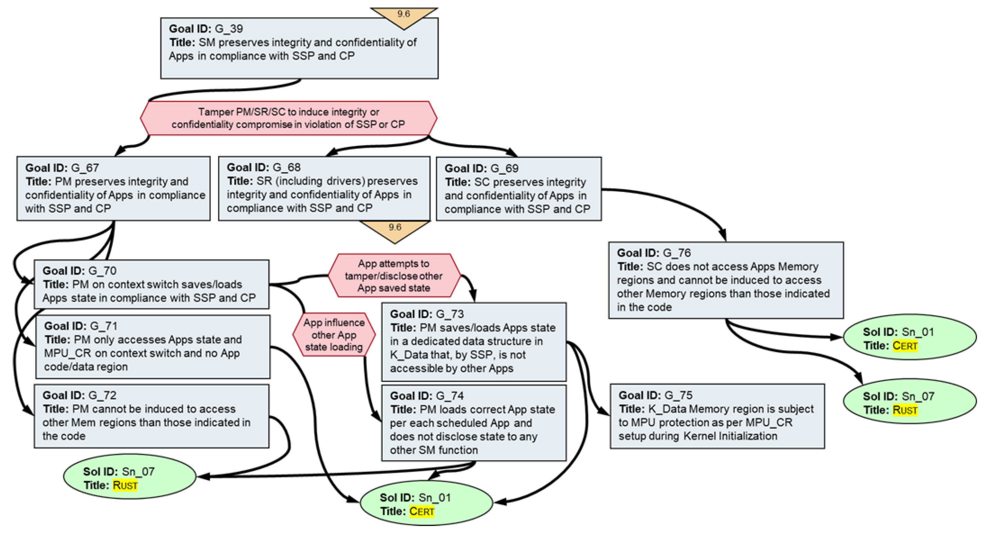
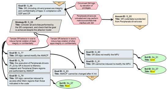
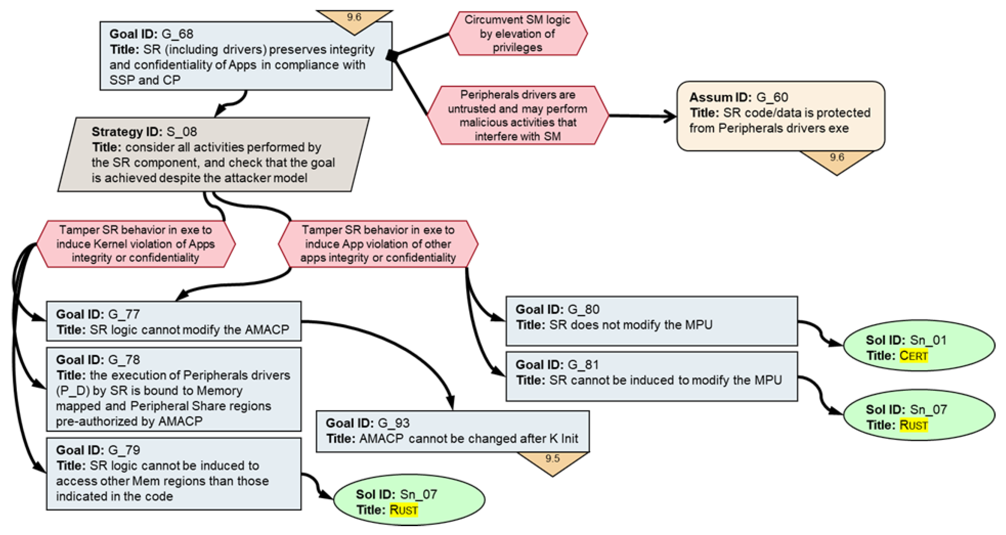
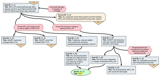
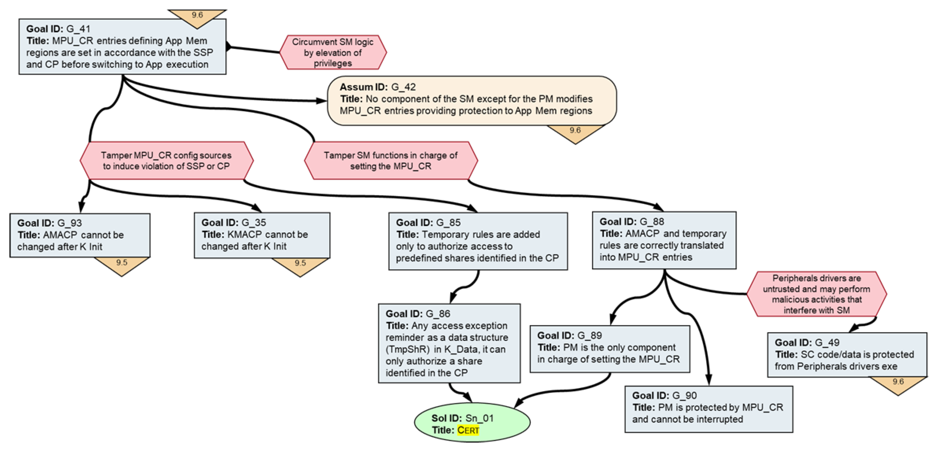
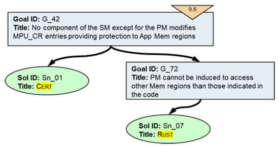
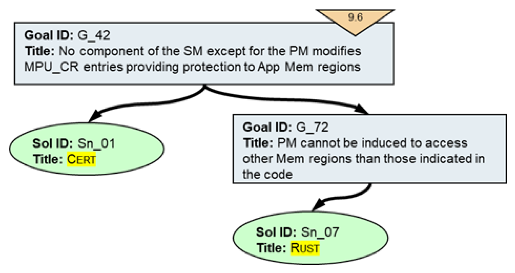
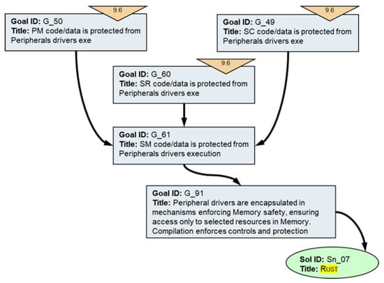
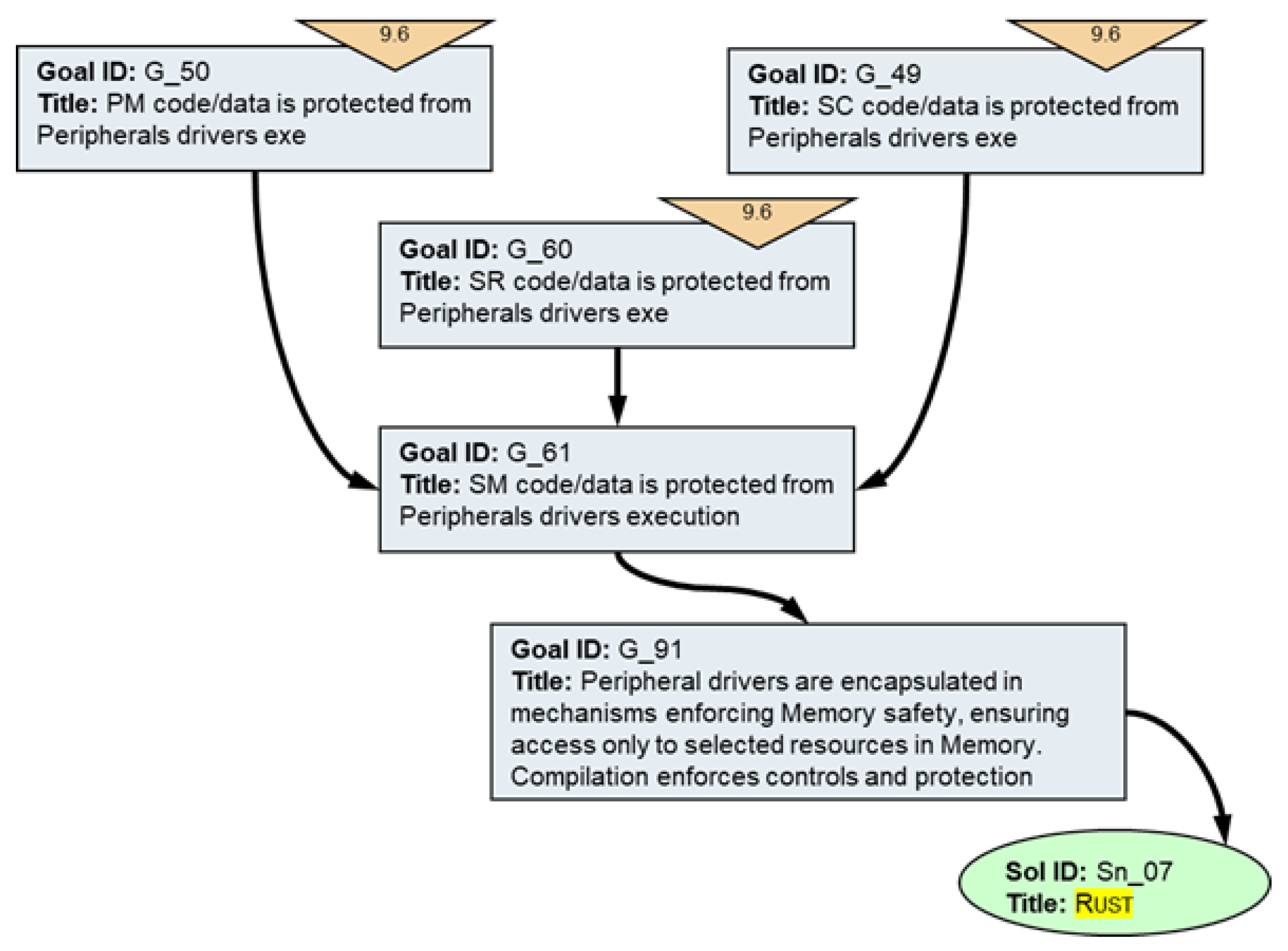
Disclaimer/Publisher’s Note: The statements, opinions and data contained in all publications are solely those of the individual author(s) and contributor(s) and not of MDPI and/or the editor(s). MDPI and/or the editor(s) disclaim responsibility for any injury to people or property resulting from any ideas, methods, instructions or products referred to in the content. |
© 2026 by the authors. Licensee MDPI, Basel, Switzerland. This article is an open access article distributed under the terms and conditions of the Creative Commons Attribution (CC BY) license.