


Abstract
With the large-scale integration of renewable energy sources, grid-forming (GFM) converters with inherent voltage and frequency support capabilities have attracted significant attention. However, due to the limited overcurrent withstand capability of power electronic devices, the stable operation of GFM converters under grid faults such as grid voltage sags remains a critical challenge. To address this issue, this paper systematically investigates the mechanisms of power angle instability and overcurrent generation during grid faults by a unified equivalent impedance model. Based on this analysis, a comprehensive control strategy that simultaneously considers power angle stability and overcurrent suppression is proposed. By introducing an adaptive improved observer control (AIOC), the active power reference is adaptively adjusted to enhance the power angle stability of the system. Meanwhile, the voltage reference is dynamically regulated to effectively limit the fault current while enhancing the voltage support capability. Finally, comprehensive theoretical analysis and experimental validation are provided. The experimental results demonstrate that the proposed strategy is capable of ensuring power angle stability and limits the overcurrent to within 1.5 p.u. Meanwhile, the voltage magnitude is increased by approximately 6%. The results demonstrate the robustness and adaptability of the proposed method under various conditions.
1. Introduction
With the continuous increase in renewable energy penetration in power systems, renewable energy generation—represented by wind and photovoltaic power—is rapidly replacing conventional fossil-fuel-based generation and gradually becoming a dominant component of modern power systems [1]. Recent energy systems research has highlighted the need for adaptive operational frameworks to accommodate high renewable penetration and associated uncertainties [2]. In parallel, studies on photovoltaic performance under climate change scenarios indicate that future grids must rely on inherently resilient and grid-supportive converter technologies [3]. As the key interface for integrating renewable energy, converter control strategies play a critical role in ensuring system stability and operational security. Conventional grid-following control schemes rely on the magnitude and phase of the grid voltage and therefore exhibit satisfactory performance under strong grid strengths with well-defined operating points. However, in weak grid strengths with high renewable penetration, the effective grid impedance increases and operating points become highly variable, rendering traditional grid-following converters more susceptible to instability and disconnection [4].
Against this background, grid-forming (GFM) control technology has emerged. GFM converters emulate the physical characteristics of synchronous generators and actively provide voltage and frequency support to the grid. They exhibit inertia and damping characteristics analogous to those of virtual synchronous machines, which can significantly enhance grid stability and robustness. Consequently, the GFM converter is widely regarded as a key enabling technology for the development of high-renewable-penetration power systems [5].
Although GFM control can enhance grid support capability, it still faces significant challenges under grid fault conditions, particularly the overcurrent and loss of synchronization (LOS) issues caused by grid faults. Unlike grid-following converters, which rely on phase-locked loop (PLL) to rapidly align with the grid phase, the output voltage phase of the GFM converter is autonomously determined by the internal control loops. When grid faults occur, the rapid sag in the point of common coupling (PCC) voltage creates a substantial potential difference between the converter terminal voltage and the faulted grid voltage, thereby inducing transient currents far exceeding the rated value [6]. Due to the limited overload capability and thermal capacity of power electronic devices, such overcurrent can easily trigger protection mechanisms, forcing the converter into current-limiting, blocking, or disconnection modes. This significantly degrades the fault ride through capability of renewable energy units and may further amplify operational uncertainties in the power system [7,8]. Meanwhile, during grid faults, the output power of the converter is constrained, and the stable equilibrium point (SEP) may disappear or shift, increasing the risk of power angle instability [9]. Therefore, achieving a coordinated design that ensures both “controllable current” and “guaranteed synchronous stability” under fault scenarios has become one of the critical challenges that must be addressed for the practical deployment of the GFM technologies.
To address the aforementioned issues, extensive research has been conducted. In the area of fault overcurrent suppression, studies in [10,11] propose switching GFM control to grid-following control during fault conditions to directly limit the converter output current. However, such approaches may compromise the GFM characteristics of the converter, potentially leading to additional transient disturbances in systems with high renewable energy penetration. In [12], a fault ride-through strategy based on the controllable line-commutated converter (CLCC) is proposed, in which forced commutation in coordination with surge arresters is employed to effectively suppress overcurrent and overvoltage during fault conditions. Virtual impedance–based methods have attracted increasing attention in recent years. Reference [13] proposes a strategy that combines external power commands with virtual impedance, where the power command regulates the steady-state fault current while the virtual impedance suppresses transient overcurrent. Reference [14] further develop adaptive virtual impedance schemes that dynamically adjust the impedance according to real-time evaluation of short-circuit current exceedance, thereby effectively limiting transient currents. Nevertheless, the introduction of virtual impedance inevitably reduces the output power capability. By contrast, current-saturation-based limiting strategies, owing to simple structure and ease of implementation, have been widely applied in the GFM converter. These methods directly introduce saturation constraints on the current reference within the inner current loop to restrict the output current. Depending on the specific implementation, common approaches include d-axis limiters, q-axis limiters, and circular current limiters [15].
Regarding the enhancement of synchronous stability, considerable efforts have been devoted to related control strategies. References [16,17] improve fault ride-through capability by suppressing power angle excursions through the reduction of the active power reference, thereby mitigating the risk of LOS during grid faults. Reference [18] further proposes reshaping the power angle characteristic curve of the GFM converter via the introduction of auxiliary control loops, which effectively enhances transient synchronous stability. In addition, reference [19] presents a virtual power control strategy that preserves the existence of a SEP without decreasing the active power reference. Although this approach can improve stability from a control perspective, it does not accurately reflect the actual output power of the converter, which may limit its practical applicability.
To fill the identified research gap, this paper proposes a comprehensive transient performance enhancement strategy for the GFM converter during grid faults. Specifically, an adaptive improved observer control (AIOC) method is introduced to dynamically regulate the power reference, thereby improving synchronization stability. Furthermore, a voltage reference regulation mechanism is integrated to achieve precise current limitation while simultaneously enhancing voltage support capability. Through the coordinated implementation of these methods, comprehensive performance improvement of the GFM converter under fault conditions is realized.
The rest of this paper is organized as follows. In Section 2, the potential power angle instability and overcurrent issues of the GFM converter under grid faults are analyzed, based on virtual admittance combined with PI control. In Section 3, the proposed method is presented in detail, where the AIOC is employed to enhance system synchronous stability, and the voltage reference is adjusted to effectively limit overcurrent. In Section 4, validates the effectiveness of the proposed strategy through experiments and examines its adaptability under various grid voltage sags. Finally, the conclusions are drawn in Section 5.
2. Transient Stability of the Grid-Forming Converter
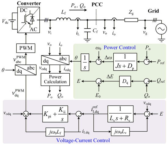
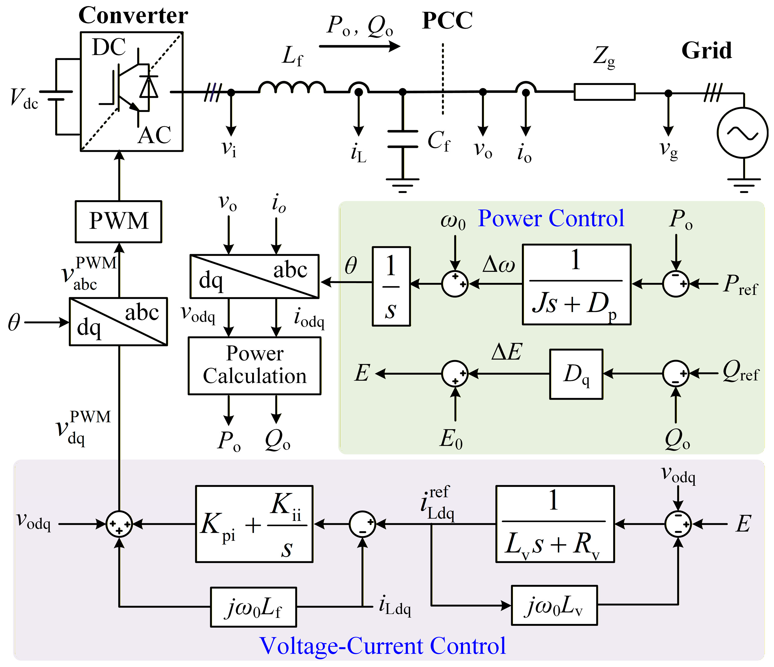
Figure 1 illustrates the overall structure of the grid-forming (GFM) converter investigated in this paper. The system mainly consists of a main power circuit, a power calculation unit, a power control loop, a voltage control loop, a current control loop, coordinate transformation modules, and a pulse width modulation (PWM) unit, forming a hierarchical control architecture from the outer loops to the inner loops.
Figure 1.
The overall structure of the GFM converter.
On the dc side, the converter is typically connected to an energy storage battery through the dc link. Owing to the fast power response capability of the energy storage system, the dc side can be approximately regarded as an ideal constant dc voltage source, denoted by Vdc. On the ac side, the inverter is connected to the point of common coupling (PCC) through an output filter, where Lf and Cf represent the filter inductance and filter capacitance, respectively. These components are employed to suppress switching harmonics and improve the quality of the output voltage and current waveforms.
The inverter output voltage and current are denoted by vo and io, respectively. The PCC is connected to the utility grid through an equivalent grid impedance Zg, which is typically modeled as a series combination of resistance and inductance to characterize the grid strength and its dynamic behavior. The corresponding grid voltage is represented by vg.
The power control loop primarily consists of an active power–frequency control loop and a reactive power–voltage control loop, which are employed to regulate the active power and voltage amplitude of the converter, respectively. In the active power control loop, the controller generates the phase angle θ, which serves as the synchronous reference for coordinate transformation. The sampled voltage and current signals undergo Park transformation, mapping the system variables to the synchronous rotating dq-reference frame (the subscript “dq” in this paper consistently denotes variables in the d-q coordinate system). In the reactive power control loop, a Qo-E control strategy is adopted to generate the internal voltage reference signal. To enhance the stability and robustness of the GFM converter under wide short-circuit ratio (SCR) operating conditions, this paper employs a combined virtual admittance and PI-based voltage–current dual-loop control structure. Specifically, the voltage outer loop generates the reference command for the current loop based on voltage deviation to achieve effective output voltage regulation. The current inner loop utilizes a PI controller for fast and accurate tracking of the current reference signal, thereby suppressing current tracking errors and improving the system’s dynamic response performance.
The output of the current loop is converted from the dq-reference frame back to the abc-reference frame. Subsequently, the PWM modulation signal is generated and applied as the switching drive signal to the power devices, ultimately realizing stable output of approximately sinusoidal voltage and current on the AC side.
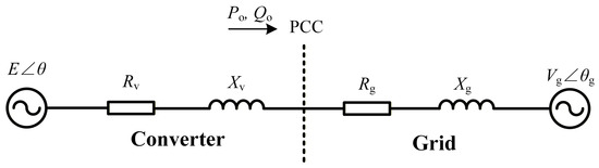
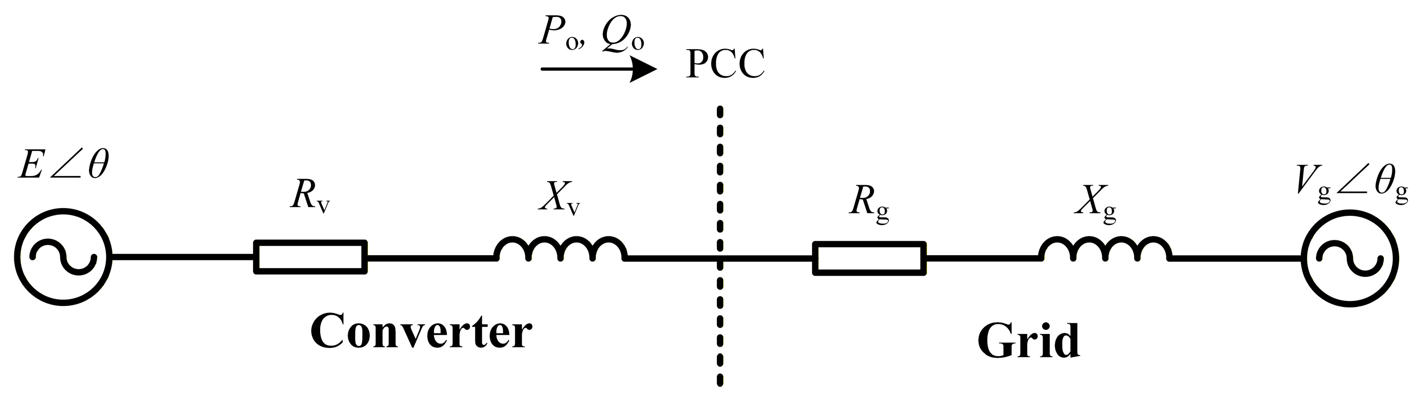
Figure 2 illustrates the equivalent circuit model of the system, which mainly consists of two parts: the equivalent circuit of the converter and the equivalent impedance of the grid. The equivalent impedances on both sides are represented by series-connected resistive and inductive components.
Figure 2.
Equivalent circuit model of the GFM converter.
In Figure 2, Rv and Xv represent the resistive and reactive components of the virtual impedance introduced by the GFM converter, respectively, while Rg and Xg denote the equivalent resistance and inductive reactance of the grid impedance. In practical scenarios, the resistive component is typically much smaller than the inductive component, i.e., R ≪ X. However, this assumption is invalid for distribution network applications with high R/X ratios. Therefore, to simplify the analysis without compromising the representation of key physical mechanisms, this paper neglects the resistive elements of the system and considers only the influence of inductive impedance.
Regarding the coordinate system definition, this paper stipulates that the internal voltage reference E aligns with the d-axis. Furthermore, δ is defined as the power angle, characterized by the phase difference between the internal voltage reference and the grid voltage, defined as δ = θ − θg, where θ and θg represent the phase angles of the internal voltage reference and the grid voltage, respectively.
Based on the above analysis, the output power expression of the GFM converter can be further derived as:
where XΣ represents the equivalent total inductive reactance of the system, expressed as: XΣ = Xv + Xg.
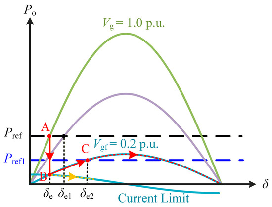
Based on Equation (1), considering the fault scenario of the grid voltage sag, the Po-δ characteristic curves of the GFM converter under different magnitudes of the grid voltage Vg are plotted for both pre-fault and post-fault conditions, as illustrated in Figure 3.
Figure 3.
Po-δ curves of the GFM converter.
As shown in Figure 3, under normal operating conditions (green curve), the system exhibits a stable equilibrium point (SEP) A with a corresponding power angle δe, where the system remains in a stable state. Upon the occurrence of a grid voltage sag, the Po-δ characteristic curve shifts to the purple curve, maintaining a SEP at δe1.
However, as the grid voltage further sags (e.g., Vg = 0.2 p.u.), no SEP exists under the original active power reference Pref, leading to loss of synchronization (LOS). To restore system stability, it becomes necessary to reduce the active power reference to Pref1, at which point the system regains a SEP with a power angle of δe2.
During fault progression, the operating point migrates along the trajectory A→B→C, as indicated by the solid red line. Notably, under current-limiting operation, the Po-δ curve shifts further downward (yellow dashed curve), eliminating the stable equilibrium point even at Pref1.
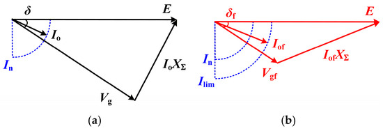
Figure 4 illustrates the phasor diagrams of the GFM converter under normal operating and grid fault conditions.
Figure 4.
Vector diagrams of the GFM converter under different operating conditions. (a) Normal mode. (b) Grid fault mode.
As shown in Figure 4a, under normal mode, the magnitude of the output current Io of the GFM converter is effectively regulated within the range of the rated current value In, ensuring stable system operation. However, when the grid voltage Vg sags, the converter is forced to increase the output current in order to maintain the predefined power transfer requirement. As a result, the magnitude of the output current may rise sharply within a short time interval. In the case of severe voltage sag, the output current can rapidly exceed the rated value, potentially reaching several times the rated current, which may trigger overcurrent stress on power electronic devices or activate protection mechanisms, as depicted in Figure 4b. To distinguish the during-fault operating state from the normal condition, electrical variables after the fault are denoted by the subscript “f”.
Given that the aperiodic inrush current generated during the initial stage of a grid fault has a short duration and its impact on subsequent operation characteristics is relatively limited, this paper reasonably neglects this transient process. Accordingly, the periodic overcurrent under grid faults can be expressed in the following form [20].
As evidenced by the preceding analysis, transient power angle instability and fault induced overcurrent emerge as two predominant challenges during grid faults. To address these issues, this paper proposes a novel control methodology specifically designed to enhance the transient performance of the GFM converters.
3. Proposed Transient Performance Enhancement Strategy
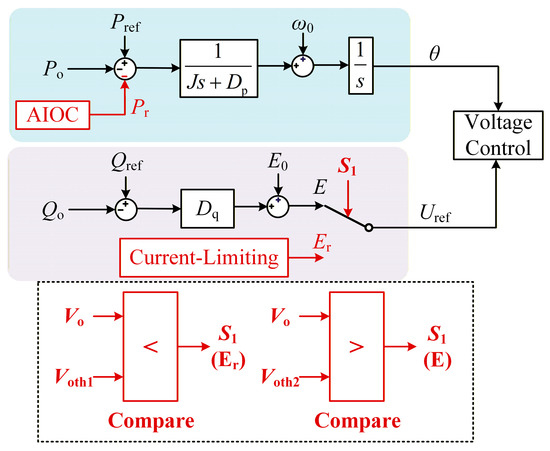
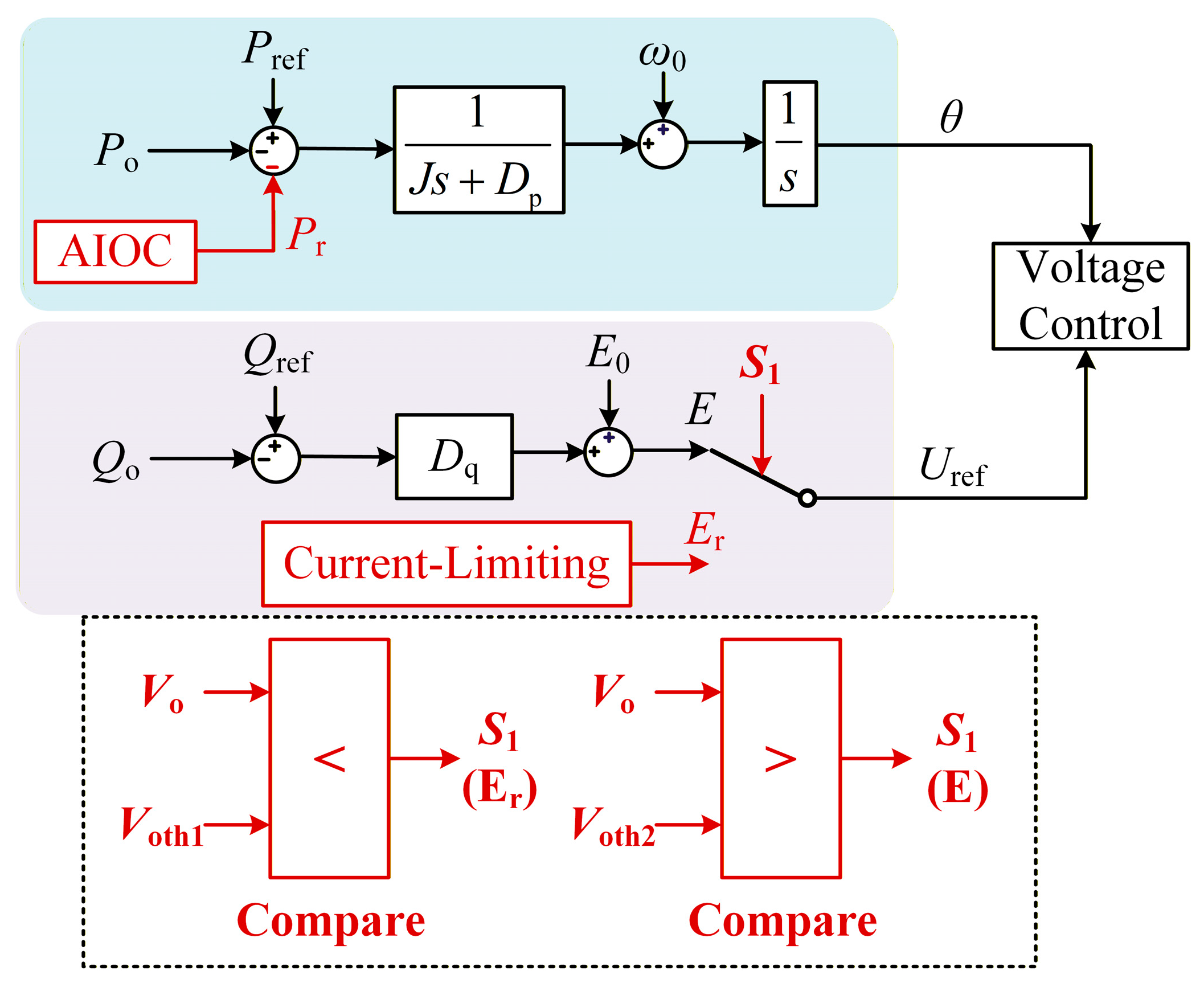
In Section 2, the adverse impacts of grid faults on the transient power angle stability of the GFM converter, as well as the pronounced increase in fault current, are analyzed. Building upon these findings, a novel control strategy is proposed in this paper. The overall control architecture of the proposed strategy is illustrated in Figure 5.
Figure 5.
The overall control architecture of the proposed strategy.
The proposed strategy primarily employs adaptive improved observer control (AIOC) to regulate the reference active power Pref of the GFM converter, thereby ensuring transient power angle stability. Subsequently, the reference voltage at the output of the reactive power control loop is adjusted to limit the steady-state fault current. Detailed analysis of these components will be presented in subsequent sections.
3.1. Adaptive Power Reference Regulation Based on AIOC
As analyzed in Section 2, under grid faults, the mismatch between the converter output power and the reference power leads to an increase in the power angle, which may eventually result in LOS. This issue can be effectively mitigated by reducing the active power reference. Based on the swing equation of the GFM converter, this paper develops an adaptive optimal observer-based control strategy. The proposed approach dynamically regulates the active power reference by monitoring system states in real time, thereby suppressing excessive power-angle deviation and enhancing transient stability.
Accordingly, the dynamic equation of the active power control loop illustrated in Figure 1 can be expressed as:
where J denotes the virtual inertia introduced by the GFM converter, Dp represents the virtual damping coefficient, ω is the angular frequency generated by the active power control loop, and ω0 denotes the rated angular frequency.
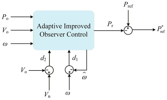
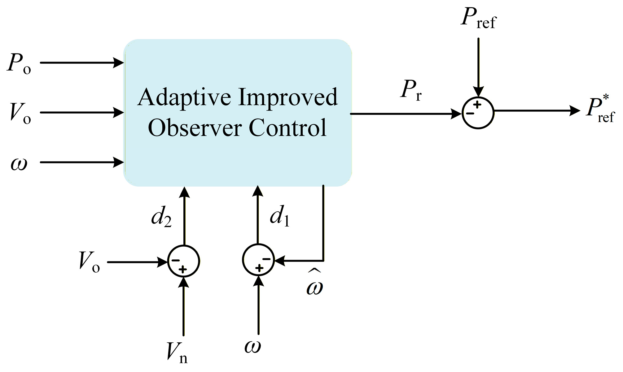
Based on Equation (3), an AIOC model is formulated by jointly considering the voltage and frequency signals, as expressed as follows:
where the symbol ‘^’ represents the estimated variable, while the superscript ‘·’ indicates a differentiation of variables. The term d denotes the deviation between the estimated angular frequency and the actual angular frequency, d1 represents the angular frequency error, and d2 represents the voltage magnitude error, where Vₙ represents the rated voltage and Vₒ corresponds to the magnitude at the PCC, i.e., Vo = (Vod2 + Voq2)1/2. The observer gain coefficients are defined as kv, kp, and kω, respectively.
It can be observed from Equation (4) that, under grid faults, Vₒ decreases to different levels depending on the depth of the grid voltage sag, while ω varies according to the severity of the fault. Consequently, when the grid voltage sags, the total disturbance acting on the system becomes nonzero. This disturbance term is jointly related to the voltage sag depth and the power angle and thus exhibits a pronounced nonlinear characteristic. Based on this term, the active power reference Pref is adjusted to eliminate the system error while enhancing transient stability. The corresponding expression is given by:
where, Pr denotes the adjustment of the active power reference, aimed at compensating the disturbance and achieving steady-state operation. The detailed structure of this regulation strategy is illustrated in Figure 6.
Figure 6.
The structure of the AIOC.
Therefore, it can be concluded from the above equation that the power reference observation generated by the AIOC method serves as a critical control variable for enhancing power system synchronization stability. Consequently, the observation accuracy and dynamic performance of AIOC are of paramount importance. The parameter design can be achieved by constructing an error dynamic system.
Based on the above analysis, the variable error is defined as the dynamic deviation between the actual output and the estimated value from the AIOC observer, expressed mathematically as:
By substituting Equations (3) and (4) into Equation (6), the following expression is derived through derivation:
where the symbol ‘~’ denotes the corresponding error variables, and K represents the coefficient relating the voltage and the power angle, which is derived from (1), i.e., .
Furthermore, Equation (7) can be simplified, and the equivalent form can be expressed as follows:
Therefore, the corresponding parameters of the AIOC controller can be determined based on Equation (8) in conjunction with the system stability criteria.
3.2. Overcurrent Suppression
As analyzed in Section 2, when the grid voltage sags, the vectorial relationship between voltage and current may lead to overcurrent in the converter, potentially compromising system operational safety.
According to Equation (2), under grid faults, the magnitude of the overcurrent is primarily influenced by the grid voltage Vg, the internal voltage reference E, the equivalent impedance XƩ, and the power angle δ.
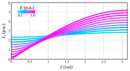
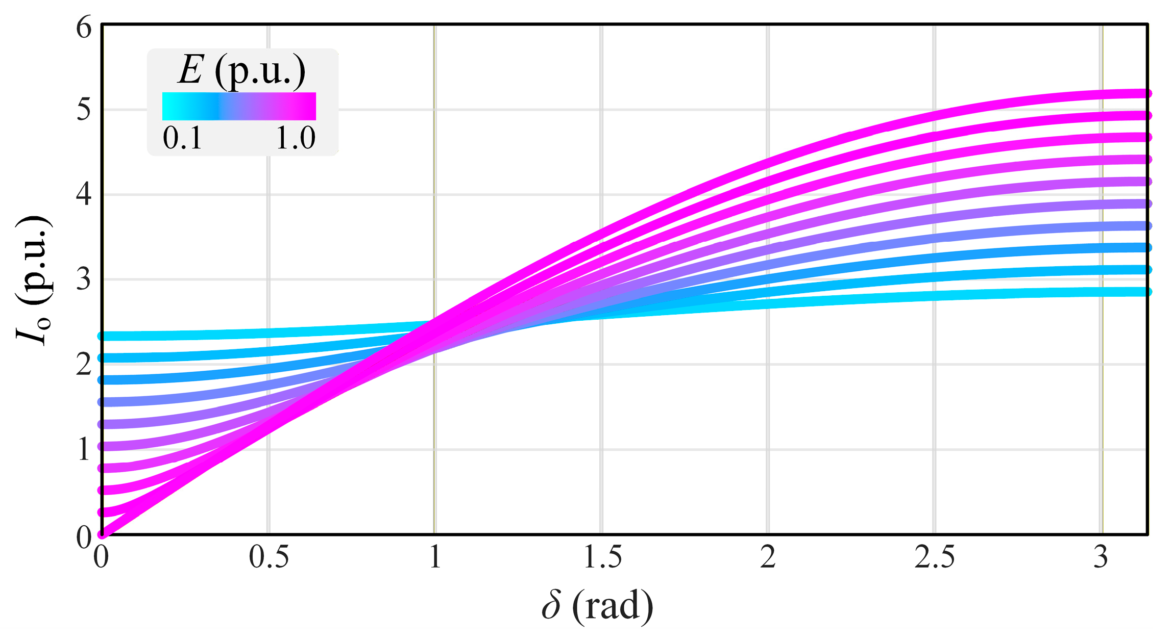
Figure 7 illustrates the influence of different internal voltage references on the output current. As shown in Figure 7, when the power angle is within a small range, decreasing the internal voltage reference results in an increase in the magnitude of the output current. However, as the power angle increases beyond a certain point, the trend reverses, and a reduction in voltage leads to a decrease in the current magnitude. Furthermore, even with a constant internal voltage, the output current magnitude still exhibits significant fluctuations with changes in the power angle. These observations indicate that the power angle not only determines the phase relationship between voltage and current but also significantly affects the magnitude of the current during fault conditions, revealing the coupled effect of voltage magnitude and power angle on the current response.
Figure 7.
The influence of different E on the output current.
Since Vg and δ are difficult to directly control, and impedance-based regulation is relatively complex, this paper proposes an effective current-limiting approach by adjusting the internal voltage reference.
The proposed method simplifies the control strategy while enhancing the operability and responsiveness of the current-limiting action. The control structure is illustrated by the purple region in Figure 2. Under normal operating conditions, switch S1 remains inactive, the reactive power control loop structure remains unchanged, and the internal voltage reference E is output, with E = Uref, where Uref denotes the voltage reference signal. When the output voltage magnitude falls below the threshold Voth1 (Voth1 corresponds to the voltage magnitude at which the GFM converter can operate normally under conditions of low SCR.) a fault is detected, causing S1 to switch and bypass the reactive power control loop. At this point, Er = Uref, and the output current is indirectly limited by adjusting the voltage reference signal. When the output voltage magnitude exceeds the upper threshold Voth2 (with Voth2 > Voth1), the system is considered to have returned to normal operation. At this point, S1 switches back, and the voltage reference is restored to E.
The primary objective of the current limiting strategy is to constrain the magnitude of the output current. According to Equation (2), the expression of the current magnitude can be written as:
Since the power angle is difficult to directly control and accurately measure, it is necessary to eliminate the power angle terms in Equation (9) during the analysis and control design.
Based on Equation (1), the sine expression of the power angle can be derived as:
By combining Equations (9) and (10), and exploiting the trigonometric identity sin2δ + cos2δ = 1, the terms related to the power angle in the current magnitude expression can be eliminated, yielding the following result.
Equation (11) can be further reformulated as:
Based on Equation (12), the expression of the internal voltage reference incorporating the current magnitude constraint can be derived as:
where A and B respectively denote:
According to (13), different current magnitudes correspond to different Er. Therefore, when the output current equals the current limit value, i.e., Io = Ilim, the corresponding Er can be selected to effectively constrain the current magnitude to the desired level under grid faults.
The grid impedance is obtained using the method proposed in [21]. However, in practical operation, accurate measurement of the grid voltage is challenging, making it difficult to directly apply in the control loop. To address this issue, the magnitude of the output voltage Vo is employed as a substitute, thereby avoiding reliance on hard-to-measure parameters. Meanwhile, a regulation coefficient KL is introduced to compensate for the deviation caused by the parameter substitution, enabling effective correction and adaptive adjustment of the voltage regulation term.
Therefore, under the current-limiting mode, the expressions of Er, A and B are correspondingly modified as follows:
4. Experiment Verification
Due to the complex operating conditions associated with grid voltage sags and the low voltage ride through (LVRT) response testing of the GFM converter, experimental validation is conducted using a Hardware-in-the-Loop (HIL) platform to verify the effectiveness of the proposed transient stability enhancement strategy. The real-time simulator StarSim 6020 is used to model power circuits. The controller for the GFM inverter was implemented on the MT1038 controller using the DSP TMS320F28388D. Compared with conventional experimental approaches, HIL technology enables real-time validation of control algorithms while ensuring experimental safety. Additionally, the HIL framework supports model-based interaction with realistic environments, combining high-fidelity simulation with the repeatability of experimental testing. In the experimental setup, the DC-side voltage is set to 1300 V, and an LC filter is employed at the output to suppress high frequency harmonic components. The main circuit and control parameters used in the experiment are consistent with those listed in Table 1.
Table 1.
GFM Converter Parameters.
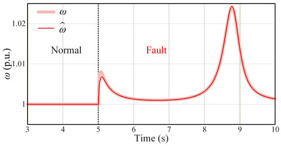
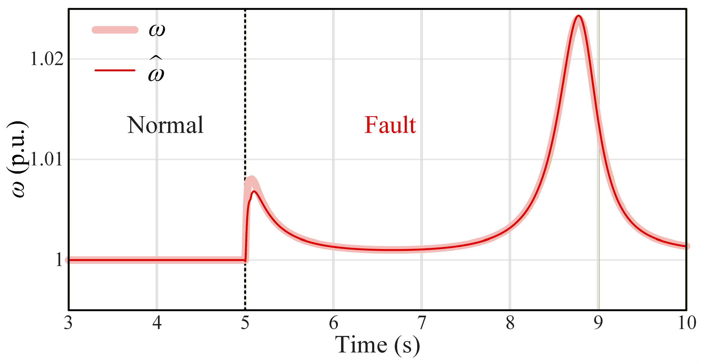
Figure 8 illustrates the comparison between the estimated angular frequency under the proposed AIOC strategy. and the actual output of the active power loop. At t = 5 s, a grid fault occurs, causing the grid voltage to sag sharply from 1 p.u. to 0.2 p.u. It can be indicated that under normal mode, AIOC achieves high-accuracy estimation of the angular frequency, with the estimated value closely matching the actual value. After the system enters the fault mode, despite the severe voltage sag, the estimated angular frequency can still rapidly and smoothly track the actual variation, with only a brief deviation observed at the instant of fault occurrence. These results demonstrate that the proposed AIOC strategy exhibits excellent dynamic performance and robustness under different operating states.
Figure 8.
Comparison between the estimated angular frequency based on AIOC and the actual value.
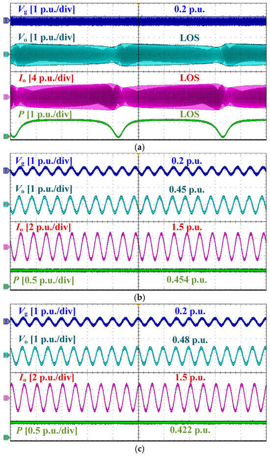
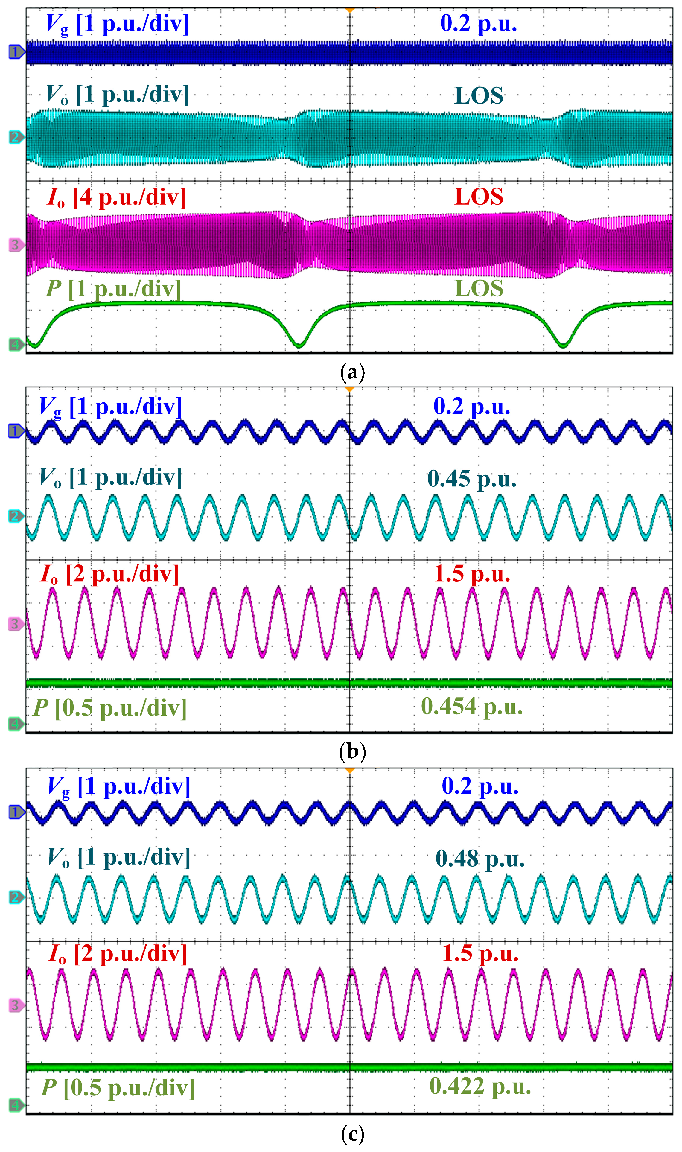
Figure 9 presents a comparative experimental evaluation of the FRT responses of the GFM converter under different control strategies when the grid voltage sags to 0.2 p.u. Figure 9a corresponds to the case without any strategy. It can be observed that after the voltage sag, the absence of a SEP leads to pronounced oscillations in the active power of the GFM converter, which progressively diverge and ultimately result in LOS. Meanwhile, the current magnitude significantly exceeds the rated value, giving rise to a pronounced overcurrent condition.
Figure 9.
Comparison of output waveforms under a grid voltage sag to 0.2 p.u.: (a) Without any strategy. (b) With reduced power reference and a circular current limiter. (c) With the proposed strategy (AIOC method considering current limitation).
Figure 9b illustrates the dynamic response under the power regulation strategy combined with a circular current limiter [22], while Figure 9c presents the experimental response using the proposed strategy. The results indicate that, under grid faults, both strategies are capable of reducing the power reference to maintain synchronous stability and effectively limiting the fault current to below 1.5 p.u. However, compared with the output voltage magnitude of approximately 0.45 p.u. in Figure 9b, the proposed strategy achieves an increased output voltage magnitude of about 0.48 p.u., corresponding to an improvement of approximately 6%. According to the research in [23], a higher voltage magnitude at the PCC during grid faults generally indicates stronger voltage support capability. Therefore, the obtained waveforms further verify the superior voltage support capability of the proposed strategy.
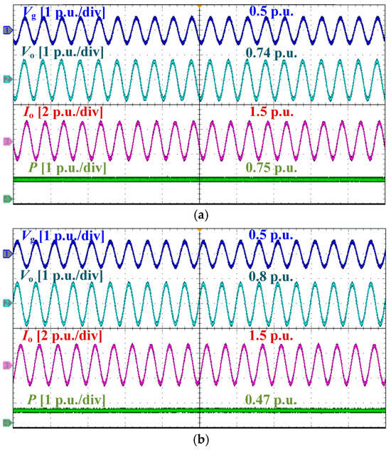
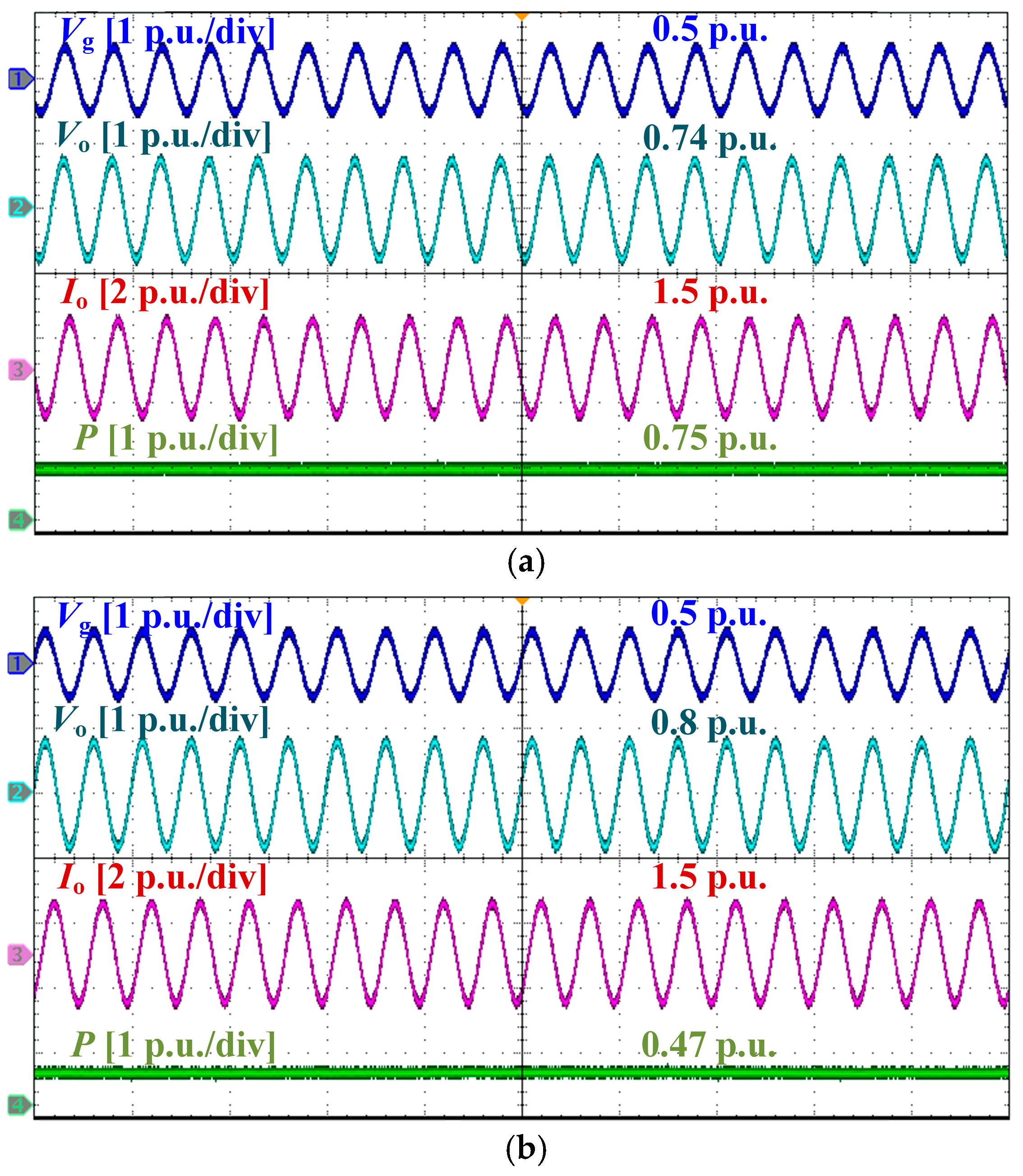
Figure 10 presents a comparison of the dynamic responses under different control strategies when the grid voltage sags to 0.5 p.u. It can be observed that, with the proposed strategy, the system not only maintains synchronous stability and effectively limits the fault current, but also achieves an output voltage magnitude of 0.8 p.u., representing a notable improvement over the case with the power regulation strategy combined with a circular current limiter.
Figure 10.
Comparison of output waveforms under a grid voltage sag to 0.5 p.u.: (a) With reduced power reference and a circular current limiter. (b) With the proposed strategy (AIOC method considering current limitation).
In summary, under various grid fault conditions, the proposed strategy effectively enhances the synchronization stability of the grid-forming converter, ensures reliable fault current limitation, and improves the voltage support capability, demonstrating sustained effectiveness.
5. Conclusions
This paper focuses on the problems of LOS and overcurrent encountered by the GFM converter under grid faults. Firstly, based on the equivalent impedance model, the mechanisms of synchronous instability and the key factors affecting fault current under grid faults are systematically analyzed. On this basis, to improve the transient performance, a comprehensive control strategy that considers both power angle stability and overcurrent suppression is proposed. By introducing an adaptive improved observer control, the active power reference is adaptively adjusted when a grid fault occurs, thereby enhancing the transient power angle stability of the system. Meanwhile, by dynamically regulating the voltage reference, effective current limiting during faults is achieved and the voltage support capability is improved. Finally, the effectiveness of the proposed strategy is thoroughly validated through theoretical analysis and experimental results. The results demonstrate that the proposed method exhibits adaptability under different depths of voltage sags.
Author Contributions
Methodology, W.C., H.Z., J.Z. and F.W. (Feng Wang); software, D.W., F.W. (Feixing Wang) and K.L.; validation, Y.X.; writing—original draft, Z.X. and W.L.; supervision, D.Z., X.Y. and Y.W. All authors have read and agreed to the published version of the manuscript.
Funding
This research received no external funding.
Data Availability Statement
The original contributions presented in the study are included in the article; further inquiries can be directed to the corresponding author.
Conflicts of Interest
Authors Wei Chen, Dingyun Wen and Feixing Wang were employed by State Grid Gansu Electric Power Company, Lanzhou, China. Authors Hang Zhang, Jia Zhang, Feng Wang and Kang Liu were employed by State Grid Gansu Electric Power Research Institute, Lanzhou, China. Author Yuanzhen Xu was employed by NR Electric Co., Ltd., Nanjing, China. The remaining authors declare that the research was conducted in the absence of any commercial or financial relationships that could be construed as a potential conflict of interest.
Abbreviations
The following abbreviations are used in this manuscript:
| GFM | Grid-forming |
| LOS | Loss of synchronization |
| SCR | Short circuit ratio |
| SEP | Stable equilibrium point |
| AIOC | Adaptive improved observer control |
References
- Kouro, S.; Leon, J.I.; Vinnikov, D.; Franquelo, L.G. Grid-Connected Photovoltaic Systems: An Overview of Recent Research and Emerging PV Converter Technology. IEEE Ind. Electron. Mag. 2015, 9, 47–61. [Google Scholar] [CrossRef] [Scilit]
- Wu, H.; Qiu, D.; Zhang, L.; Sun, M. Adaptive multi-agent reinforcement learning for flexible resource management in a virtual power plant with dynamic participating multi-energy buildings. Appl. Energy 2024, 374, 123998. [Google Scholar] [CrossRef] [Scilit]
- Wu, H.; Kong, Q.; Huber, M.; Sun, M.; Craig, M.T. Climate change will increase high-temperature risks, degradation, and costs of rooftop photovoltaics globally. Joule 2025, 10, 102218. [Google Scholar] [CrossRef] [Scilit]
- Rosso, R.; Wang, X.; Liserre, M.; Lu, X.; Engelken, S. Grid-Forming Converters: Control Approaches, Grid-Synchronization, and Future Trends—A Review. IEEE Open J. Ind. Appl. 2021, 2, 93–109. [Google Scholar] [CrossRef] [Scilit]
- Fan, B.; Liu, T.; Zhao, F.; Wu, H.; Wang, X. A Review of Current-Limiting Control of Grid-Forming Inverters Under Symmetrical Disturbances. IEEE Open J. Power Electron. 2022, 3, 955–969. [Google Scholar] [CrossRef] [Scilit]
- Wang, X.; Blaabjerg, F. Harmonic stability in power electronic based power systems: Concept, Modeling, and Analysis. IEEE Trans. Smart Grid 2018, 10, 2858–2870. [Google Scholar] [CrossRef] [Scilit]
- Bottrell, N.; Green, T.C. Comparison of current-limiting strategies during fault ride-through of inverters to prevent latch-up and wind-Up. IEEE Trans. Power Electron. 2013, 29, 3786–3797. [Google Scholar] [CrossRef] [Scilit]
- Baeckeland, N.; Chatterjee, D.; Lu, M.; Johnson, B.; Seo, G.-S. Overcurrent Limiting in Grid-Forming Inverters: A Comprehensive Review and Discussion. IEEE Trans. Power Electron. 2024, 39, 14493–14517. [Google Scholar] [CrossRef] [Scilit]
- Shuai, Z.; Shen, C.; Liu, X.; Li, Z.; Shen, Z.J. Transient angle stability of virtual synchronous generators using Lyapunov’s direct method. IEEE Trans. Smart Grid 2018, 10, 4648–4661. [Google Scholar] [CrossRef] [Scilit]
- Schweizer, M.; Almer, S.; Pettersson, S.; Merkert, A.; Bergemann, V.; Harnefors, L. Grid-Forming Vector Current Control. IEEE Trans. Power Electron. 2022, 37, 13091–13106. [Google Scholar] [CrossRef] [Scilit]
- Almesri, Z.M.; Hussain, H.A.; Kamel, R.M. Low Voltage Ride-Through Capability of Grid-Connected PV Systems: A Comparative Study of Grid-Following and Grid-Forming Converters Under Current Limits. IEEE Access 2025, 13, 105590–105607. [Google Scholar] [CrossRef] [Scilit]
- Liu, K.; Li, B.; Jiang, Q.; Zhang, Y.; Liu, T. Fault Ride-Through Strategy for Hybrid Cascaded HVdc Systems Based on Controllable LCC. IEEE Trans. Circuits Syst. II Express Briefs 2025, 73, 88–92. [Google Scholar] [CrossRef] [Scilit]
- Liu, T.; Wang, X.; Liu, F.; Xin, K.; Liu, Y. A Current Limiting Method for Single-Loop Voltage-Magnitude Controlled Grid-Forming Converters During Symmetrical Faults. IEEE Trans. Power Electron. 2021, 37, 4751–4763. [Google Scholar] [CrossRef] [Scilit]
- Paquette, A.D.; Divan, D.M. Virtual Impedance Current Limiting for Inverters in Microgrids With Synchronous Generators. IEEE Trans. Ind. Appl. 2014, 51, 1630–1638. [Google Scholar] [CrossRef] [Scilit]
- Zhang, Y.; Zhang, C.; Yang, R.; Molinas, M.; Cai, X. Current-Constrained Power-Angle Characterization Method for Transient Stability Analysis of Grid-Forming Voltage Source Converters. IEEE Trans. Energy Convers. 2023, 38, 1338–1349. [Google Scholar] [CrossRef] [Scilit]
- Wu, H.; Wang, X. A mode-adaptive power-angle control method for transient stability enhancement of virtual synchronous generators. IEEE J. Emerg. Sel. Top. Power Electron. 2020, 8, 1034–1049. [Google Scholar] [CrossRef] [Scilit]
- Taul, M.G.; Wang, X.; Davari, P.; Blaabjerg, F. Current Limiting Control with Enhanced Dynamics of Grid-Forming Converters During Fault Conditions. IEEE J. Emerg. Sel. Top. Power Electron. 2019, 8, 1062–1073. [Google Scholar] [CrossRef] [Scilit]
- Deng, H.; Qi, Y.; Fang, J.; Tang, Y.; Debusschere, V. A Robust Low-Voltage-Ride-Through Strategy for Grid-Forming Converters Based on Reactive Power Synchronization. IEEE Trans. Power Electron. 2022, 38, 346–357. [Google Scholar] [CrossRef] [Scilit]
- Baeckeland, N.; Yang, B.; Seo, G.-S. Transient Stability-Enhancing Method for Grid-Forming Inverters Under Current Limiting. IEEE Trans. Power Electron. 2025, 40, 6714–6725. [Google Scholar] [CrossRef] [Scilit]
- Xie, Z.; Zhao, T.; Tang, H.; Gong, L.; Dai, Y.; Wu, C.; Wang, Y.; Blaabjerg, F. Transient inrush current analysis and suppression for grid-forming converters under grid faults. IEEE Trans. Ind. Electron. 2025, 73, 4064–4075. [Google Scholar] [CrossRef] [Scilit]
- Wang, Q.; Li, Z.; Zhang, Z.; Zhang, Z.; Shi, S. An Accurate Reactive Power Sharing Strategy Based on adaptive Virtual Impedance Optimization. In Proceedings of the 2023 IEEE 6th International Electrical and Energy Conference (CIEEC), Hefei, China, 12–14 May 2023; pp. 4439–4444. [Google Scholar]
- Wu, C.; Zou, Z.; Xiong, X.; Wang, Y.; Blaabjerg, F. Fast active power recovery for grid-forming converter during postfault under different R/X ratios of grid impedance. IEEE Trans. Ind. Electron. 2025, 72, 10130–10140. [Google Scholar] [CrossRef] [Scilit]
- National Grid ESO. Great Britain Grid Forming Best Practice Guide. 2023. Available online: https://www.neso.energy/document/278491/download (accessed on 11 March 2026).

Disclaimer/Publisher’s Note: The statements, opinions and data contained in all publications are solely those of the individual author(s) and contributor(s) and not of MDPI and/or the editor(s). MDPI and/or the editor(s) disclaim responsibility for any injury to people or property resulting from any ideas, methods, instructions or products referred to in the content. |
© 2026 by the authors. Licensee MDPI, Basel, Switzerland. This article is an open access article distributed under the terms and conditions of the Creative Commons Attribution (CC BY) license.