


Abstract
With the deepening of fifth-generation mobile communication technology (5G) commercialization and the surge in demand for intelligent connectivity of all things, the sixth-generation mobile communication technology (6G) has entered a phase of technological breakthroughs. The innovation in antenna design will determine the upper limits of 6G communication. This paper systematically reviews the research progress on antenna technology for 6G communications, focusing on operating frequency bands, antenna structure design, and materials and packaging technologies. The development of 6G communication technology drives antenna research toward higher-frequency bands, with the current research focus extending from the millimeter wave (mmWave) band to the terahertz (THz) band. Compared to the traditional mmWave band, the THz band shows significant advantages in performance indicators. At the antenna structure level, its development trend is mainly reflected in the following three aspects: size miniaturization, scale expansion and distributed deployment, and expansion of frequency bands and functions. New materials and advanced packaging have become key enabling technologies: materials with low-loss characteristics and tunable surface conductivity have become research focuses. Meanwhile, advanced packaging processes achieve miniaturization and high-performance integration of antenna systems. This review aims to provide a systematic technical reference for the research and engineering development of next-generation 6G antennas.
1. Introduction
1.1. Background
Through decades of continuous evolution, communication technology has achieved profound development across various fields such as industry, healthcare, transportation, and public safety. By the end of 2024, the global annual flow of communication data had exceeded 3000 exabytes (EB), and it is projected that global mobile data traffic will reach 5016 EB by 2030 [1]. Enabled by 5G-Advanced networks, artificial intelligence (AI)-driven network optimization, and low earth orbit (LEO) satellite systems, the real-time transmission of information is facilitated. This transmission encompasses audio, images, and videos, and is carried out through end-user devices such as smartphones, the Internet of Things (IoT) terminals, and augmented reality/virtual reality (AR/VR) devices. As a result, communication technology has become an indispensable driver of the global economy’s digital transformation.
With the rapid development of mobile communications, the performance of mobile devices has also been continuously improving. Antennas, serving as the core hardware for transmitting and receiving electromagnetic signals, are key components for information transmission. As mobile phones have become widely adopted, their integrated antennas have likewise undergone continuous evolution. The representative device of the first-generation mobile communication technology (1G) was the world’s first mobile phone terminal, the Motorola DynaTAC 8000X, introduced in 1983. It employed external antennas such as telescopic, helical, and whip antennas, offering only voice call services with low data rates and without essential security standards [2]. In 1991, the second-generation mobile communication technology (2G) adopted digital modulation technology. The reduced size and cost of antennas facilitated the miniaturization of mobile terminals like phones while adding capabilities for short message service (SMS) and mobile internet beyond the 1G baseline. In 2000, the third-generation mobile communication technology (3G), with code division multiple access (CDMA) as its core technology, provided greater bandwidth and flexibility to meet more diverse user needs. It was characterized by simple frequency planning, large system capacity, high frequency reuse, strong anti-multipath performance, good communication quality, soft capacity, and soft handoff. However, it also introduced challenges such as spectrum scarcity and signal interference. In 2010, the fourth-generation mobile communication technology (4G) incorporated core technologies including orthogonal frequency division multiplexing (OFDM), Internet Protocol version 6 (IPv6), software-defined radio, and smart antennas. It delivered faster data rates, enhanced security, and enabled services like video calls, teleconferencing, and VR. This era saw a dramatic increase in the number of mobile devices and rapid growth in data usage per device [3]. In 2019, 5G leveraged MIMO and orthogonal frequency division multiple access (OFDMA) technologies, utilizing both low-frequency and high-frequency spectrum resources. It provides higher data rates and wider bandwidth, achieves significant gains in spectrum efficiency, and is extensively applied in domains such as intelligent transportation, smart homes, and smart manufacturing. Meanwhile, the development of antenna technology has always been built upon a mature framework of electromagnetic theory and engineering. In recent years, the critical demands for 6G have driven the rapid evolution of related technologies [4].
Against the backdrop of large-scale commercial deployment of 5G technology and the maturing of relevant international standards and regulatory frameworks, current mobile communication technologies still face challenges arising from the continuous deepening of emerging application scenarios. The International Telecommunication Union (ITU) defined the minimum requirements for 5G radio interface technology performance in Recommendation M.2410 [5], laying a crucial foundation for global 5G deployment. However, as scenarios such as holographic communication, digital twins, immersive extended reality (XR), and the smart industrial internet demand higher-dimensional communication capabilities, 5G is gradually exhibiting limitations in key performance metrics like peak data rate, latency, reliability, and connection density. Consequently, both industry and academia have initiated research and strategic planning for 6G. The ITU further proposed a future technology development framework and overall goals for 2030 and beyond in Recommendation M.2160 [6], which systematically defines new requirements that 6G must meet in terms of key performance indicators. A comparison with 5G is presented in Table 1. Beyond significant improvements in traditional communication metrics, 6G places greater emphasis on the integration and expansion of multi-dimensional capabilities. These include emerging capability dimensions such as intelligent coverage, integrated sensing and communication (ISAC), AI-native support, sustainability, system interoperability, and high-precision positioning. The enhanced and newly introduced performance scopes of 6G relative to 5G are illustrated in Figure 1. Thus, 6G represents not merely a linear enhancement in communication speed and capacity, but an evolution towards an intelligent, integrated, green, and trustworthy all-domain digital capability system. It thereby aims to lay the foundation for building a society of intelligent connectivity of all things.
Table 1.
Comparison of key performance indicators for 5G and 6G.
Figure 1.
6G capabilities.
In June 2021, the IMT-2030 (6G) Promotion Group published “White Paper on 6G Vision and Candidate Technologies,” which outlined ten potential 6G key technologies. These include New Network with Native AI, Enhanced Wireless Air Interface Technologies, Wireless Transmission Technologies on New Physical Dimensions, THz and Visible Light Technologies, ISAC, Distributed Autonomous Network Architecture, Deterministic Network, Computing-Aware Network, Integrated Terrestrial and Non-Terrestrial Network, and Native Network Security based on Multi-Lateral Trust Model [7]. In 2023, the ITU’s “Framework and Overall Objectives of the Future Development of IMT for 2030 and Beyond” (hereafter referred to as the ITU Framework Report) proposed six major application scenarios for 6G. These are Immersive Communication, Hyper Reliable and Low-Latency Communication, Massive Communication, Ubiquitous Connectivity, AI and Communication, and ISAC [6], as illustrated in Figure 2. In August 2025, the 3rd Generation Partnership Project (3GPP), an international telecommunication standards organization, held its first 6G Radio Access Network (RAN) working group meeting in Bengaluru, India, marking the formal entry of 6G technology into the standardization research phase. In this paper, the THz frequency band is defined as 0.1–10 THz (100 GHz–10,000 GHz), which deviates from the IEEE standard definition of 300 GHz–1 THz. This range is adopted throughout this text.
Figure 2.
Usage scenarios and overarching aspects of IMT-2030.
1.2. Scope and Contribution of This Review
In recent years, with the advancement of 6G, research on 6G antenna technology has expanded rapidly. Several comprehensive review articles have systematically organized this field from various perspectives. Y. Jay Guo et al. introduced key antenna technologies, including metasurfaces and reconfigurable intelligent surfaces (RISs), in-band full-duplex, mmWave and THz antennas, and wearable antennas, providing detailed analyses of multi-beam and multi-frequency antennas [8]. Shah Zaib Aslam et al. focused on cutting-edge technologies for scalable 6G antenna array systems, with emphasis on design challenges in the D-band (110–170 GHz). Their work also analyzed various device fabrication processes, including Complementary Metal Oxide Semiconductor (CMOS), BiCMOS, and III-V semiconductors, along with heterogeneous integration (HI) techniques [9]. Kimmo Rasilainen et al. paid closer attention to 6G antenna hardware technology, providing an overview of key hardware in the 100–300 GHz frequency range, including antennas, RISs, and reconfigurable antenna systems based on state-of-the-art technologies [10].
However, existing reviews tend to focus on in-depth vertical analyses of specific antenna types or single technical dimensions, lacking a holistic framework that horizontally correlates and systematically coordinates multi-dimensional design factors. Key dimensions that determine final antenna performance—such as frequency, structure, materials, and packaging—are often treated in isolation in the literature without reflecting their mutual constraints and synergistic relationships. This paper focuses on the core design dimensions of 6G antenna systems. Therefore, a key research gap lies in the absence of a comprehensive review that systematically elucidates the intricate synergistic relationships among the four core dimensions—frequency, structure, materials, and packaging—while clearly highlighting the evolutionary trend in antenna design paradigms from isolated optimization toward systemic co-design.
This paper addresses the aforementioned gap by focusing on the core design dimensions of 6G antenna systems. The panoramic view of 6G antenna technology is presented in Figure 3, and this paper is organized as follows: The Section 2 will argue for the inevitability and potential benefits of extending the operational frequency band to THz, clarifying the resulting opportunities and challenges. The Section 3 will comprehensively outline the three major evolutionary trends in antenna structures for adapting to new frequency bands and applications: miniaturization, large-scale distributed deployment, and multifunctional/multi-band integration. Miniaturized antennas, covering both low-frequency and THz ranges, involve distinct design approaches. Scale expansion and distributed deployment extend antenna arrays toward grid-based, communication–sensing–computing integration, and dynamic intelligence. Multifunctional/multi-band integration combines antennas with application scenarios, with wearable antennas, vehicle-conformal antennas, and aircraft conformal antennas being notable examples of functional fusion design. The Section 4 will systematically analyze the new material systems and advanced packaging solutions essential for achieving THz antenna performance, comparing the advantages and limitations of different materials at high frequencies and their packaging integration pathways. In conclusion, based on a synthesis of the above dimensional discussions, this paper will analyze key achievements in antennas, performance gaps, technology readiness level (TRL) assessments, and future research directions. It will particularly focus on the intrinsic logic, practical challenges, and future pathways for the multi-dimensional technical synergy of “frequency–structure–material–packaging.” Additionally, it will propose a multi-dimensional integrated solution combining “communication, sensing, and algorithms,” outlining a developmental vision for 6G antenna technology as it evolves from isolated innovation to systematic integration.
Figure 3.
6G antenna technology landscape.
2. Operating Frequency Bands for 6G Antennas
2.1. Frequency Band Allocations by International Organizations
To eliminate confusion arising from the misuse of letter-band nomenclature by other microwave frequency users, the Institute of Electrical and Electronics Engineers (IEEE) published a standard for letter designations of radar-frequency bands in 2019 [11], as shown in Table 2.
Table 2.
IEEE standard letter designations for radar-frequency bands.
In 2022, the ITU released the report “Future Technology Trends of Terrestrial International Mobile Telecommunications Systems Towards 2030 and Beyond.” The report stated that the application scenarios for IMT systems towards 2030 and beyond will require spectrum resources ranging from low frequencies to extremely high frequencies (i.e., the THz band). The higher anticipated capacity demands of future networks are driving the industry to seek wider bandwidths. This encompasses not only the THz band but also lower-frequency bands that require enhanced capacity while maintaining wide-area coverage. The spectrum resources above 100 GHz are currently underutilized, presenting potential for new services and applications to exploit these bands. Therefore, it is essential to conduct research on sub-THz and THz band resources ranging from around 100 GHz to 3 THz to secure sufficient bandwidth support [12].
In the ITU Framework Report, the IMT-2030 plan encompasses a broad range of frequency bands, from below 1 GHz to above 100 GHz. Low-frequency bands will remain crucial for achieving nationwide coverage, playing a significant role particularly in bridging the digital divide and extending deep indoor coverage. Mid-frequency bands strike a balance between wide-area coverage and capacity [6].
In June 2025, 3GPP released the study report “Study on 6G Radio,” which indicates that, from a technical perspective, the study will address frequencies up to 52.6 GHz, encompassing at least the full range of FR1 (up to 7.125 GHz), the range between FR1 and FR2-1 (covering approximately 7 GHz), and FR2-1 (24.25 GHz–52.6 GHz) [13].
2.2. Frequency Band Classifications in Related Literature
Currently, 6G communication standards are still in the research phase, and the industry is actively exploring candidate frequency bands. Multiple organizations and companies have proposed preliminary frequency band plans. For example, Samsung will conduct in-depth 6G research on the 7–24 GHz band, while Ericsson considers the 7–15 GHz band essential for meeting 6G’s high-capacity use case requirements. Similarly, Nokia anticipates that the 7–20 GHz band will serve 6G urban outdoor cells, and Qualcomm has included the 7–16 GHz band in its 6G considerations. On the regulatory front, China’s Ministry of Industry and Information Technology (MIIT) has proposed allocating the 6425–7125 MHz band for IMT (including 5G/6G) systems. Meanwhile, the U.S. Federal Communications Commission (FCC) plans to allocate the 12.7–13.25 GHz band for mobile broadband or other expanded uses [14].
Furthermore, relevant studies have systematically reviewed and classified potential frequency bands available for 5G/6G. For example, Naser Al-Falahy et al. summarized candidate frequency bands in a tabular form [15]. Among them, the centimeter wave (cmWave) and mmWave bands (approximately 3–300 GHz) are regarded as the primary shared frequency resource for both 5G and 6G. Potential candidate bands include 6.425–7.125 GHz, 7–24 GHz, 26 GHz, 28 GHz, 40 GHz, 60 GHz, 70 GHz, 80 GHz, and 90 GHz. Additionally, the study also points out that the higher sub-THz bands represent a cutting-edge spectrum direction dedicated to 6G, with possible candidate bands including 102–109 GHz, 151.5–164 GHz, 167–174.8 GHz, 209–226 GHz, and 252–275 GHz.
Michele Polese et al. point out that to target the terabit-per-second (Tbps) data rate, future 6G networks will require tens of GHz of continuous bandwidth, and that frequency bands above 100 GHz offer a potential solution [16]. The article lists the ITU allocations in this frequency range, with bands already allocated for fixed/mobile (including satellite) communications, including 122.25–130 GHz, 158.5–164 GHz, 167–174.8 GHz, 191.8–200 GHz, 231.5–235 GHz, and 238–241 GHz. Bands shared with the radio astronomy service (RAS) and permitted for fixed/mobile communications include 102–109.5 GHz, 111.8–114.5 GHz, 141–148.5 GHz, 151–155.5 GHz, 155.5–158.5 GHz, 209–226 GHz, and 252–265 GHz [16]. Therefore, the former are ideal candidate bands for 6G, while the latter would require spectrum-sharing technologies to enable 6G deployment.
In summary, based on the classification above, the 6G spectrum is envisioned to cover the sub-6 GHz band (<6 GHz), the cmWave band (6 GHz–30 GHz), the mmWave band (30–300 GHz), and the THz band (>100 GHz). Since the visible light band (400 THz to 800 THz) is not relevant to antenna design and application, it will not be discussed in this paper. It is worth emphasizing that as a key low-frequency resource shared with 5G, the sub-6 GHz band will continue to play a foundational role in 6G. It will not be replaced but will achieve further performance enhancement through key technologies such as the 6G new radio interface and intelligent network architecture. This will enable it to provide wide-area continuous coverage and high-reliability mobility support for 6G. Working in tandem with mid-to-high frequency bands, it will help build a comprehensive 6G three-dimensional network that supports all-scenario capabilities.
2.3. The THz Band: An Extension for 6G
The THz band (0.1–10 THz), as an extension of existing spectral resources, lies between microwaves and optical waves. It boasts extremely abundant spectrum resources and features such as high transmission rates, strong anti-interference capability, and ease of ISAC. This band will further meet the growing demand from diverse technologies and applications for antenna systems with Tbps-level massive capacity and ultra-high transmission rates. The THz band partially overlaps with the mmWave band (30–300 GHz). The term “sub-THz” found in some research [10] refers to the 100–300 GHz band, which is shared between the mmWave and THz bands. Meanwhile, the term “low-THz” [17] refers to the 100 GHz–1.0 THz band, all of which are potentially available for 6G communication.
Compared to lower-frequency bands, the THz band offers significant transmission advantages, which are reflected in improvements in directivity and gain, operational bandwidth, and data rate [18]. For a given physical size, a THz antenna achieves much higher gain than a low-frequency antenna. Specifically, a 300 GHz antenna has a 20 dB higher gain and a more focused beam than a 30 GHz antenna of the same size. This allows electromagnetic energy to be highly concentrated within an extremely narrow beam—a fundamental advantage dictated by its short-wavelength physical properties. For instance, the silicon lens antenna array designed by Maria Alonso-delPino et al. achieves 36 dBi directivity and 32 dBi gain across the 450–650 GHz band [19]. Similarly, the graphene hexagonal microstrip-fed MIMO antenna designed by Ruchi Agarwal et al. achieves a wide impedance bandwidth from 0.25 to 2 THz, with isolation exceeding 20 dB and a maximum peak gain above 12.5 dBi by superstrate metasurface [20]. These examples demonstrate the high gain and directivity of THz antennas. In addition, these antennas also show that THz-band antennas can achieve bandwidths exceeding 100 GHz—a capability unattainable in 5G mmWave or lower-frequency bands. This bandwidth expansion exploits abundant spectral resources and simultaneously increases the antenna’s transmission rate by tens of times. For example, the wideband 8 × 8 Butler matrix designed by Hirofumi Sasaki et al. enables 1.58 Tbps wireless transmission based on orbital angular momentum (OAM) multiplexing, with isolation greater than 15 dB spanning the 135–170 GHz range [21], which significantly enhances the wireless data rate.
THz communications will serve as a valuable addition to existing transmission schemes. Potential key applications encompass holographic communications, miniature-scale communications (inter-chip and nano-communications), ultra-high-capacity data backhaul, and short-distance ultra-high-speed transmission. Furthermore, the use of THz communication signals for high-precision positioning and high-resolution sensing constitutes another major application direction.
As a 6G key enabling technology, THz communication faces fundamental challenges in its deployment arising from the physical properties of high frequencies. These include severe path loss, high sensitivity to obstacles, significant atmospheric absorption, and the resulting limited link distance. Overcoming these challenges requires addressing the following core technologies and difficulties:
In transceiver architecture design, the constraints of short wavelengths and weak diffraction at THz frequencies necessitate transceivers with dynamic reconfigurability. This allows for rapid switching or adjustment of beams to find new propagation paths when blockage occurs. Currently, THz communication systems have three typical transceiver architectures. These include all-solid-state mixing and modulation-based systems, direct modulation-based systems, and photonic–electronic hybrid systems. A THz transceiver architecture that is miniaturized, low-cost, high-efficiency, and capable of supporting agile beam control remains a technical problem urgently needing resolution. In terms of Radio Frequency (RF) devices, to compensate for extremely high path loss and atmospheric absorption, the transmitter side requires high-output power, high-efficiency power amplification, and frequency generation devices. The receiver side relies on high-sensitivity, low-noise amplification, and frequency conversion devices, such as THz frequency converters, mixers, multipliers, and amplifiers. Currently, the operating frequencies and output power of THz devices still struggle to meet commercial demands. This necessitates exploring RF devices based on new semiconductor materials like silicon germanium (SiGe) and indium phosphide (InP). Enhancing device performance is the foundation for breaking through link distance limitations and achieving practical coverage. In baseband signal processing, fast time-varying channels originate from high mobility and blockage sensitivity. Supporting real-time Tbps-rate transmission requires ultra-fast channel sounding and estimation, high-precision beam tracking, and low-latency link control. Therefore, breakthroughs in advanced, high-speed baseband signal processing technology with low complexity and low power consumption are a prerequisite for the commercialization of THz systems. Regarding THz antennas, to directly compensate for severe path loss, it is necessary to form highly directional, strong beams. The high-frequency characteristics of the THz band force the individual antenna element dimensions to be miniaturized. To achieve high gain, a massive number of miniature elements must be integrated into ultra-large-scale arrays to synthesize an effective high-gain beam in a specific direction. The core technical bottleneck lies in the feed loss, element coupling, and manufacturing precision issues arising from ultra-high-density integration. In terms of channel measurement and modeling, the design and optimization of all the aforementioned technologies depend on a deep understanding and precise quantification of the unique and severe propagation characteristics of the THz channel. This process includes systematic measurement and research on path loss exponents in different scenarios, the attenuation and shadowing statistical characteristics of obstacles, the impact of atmospheric absorption lines, and the boundaries of effective communication distance. Therefore, conducting targeted THz channel measurements and establishing accurate, practical channel models form the theoretical foundation and essential path for assessing link feasibility, guiding system design, developing anti-blockage algorithms, and planning network deployment [6].
3. Architecture of 6G Antennas
The evolution of 6G antenna technology is underpinned by the accumulated and optimized foundations of prior generations. Concurrently, the proliferation of diverse communication requirements and application scenarios is imposing stringent demands for enhanced adaptability. These structural innovations primarily materialize in three dimensions: miniaturization in size, expansion in scale with distributed deployment, and extension in operating frequency bands and functionality.
3.1. Size Miniaturization
As the fundamental hardware for communication, antenna integration in mobile devices has been continuously optimized with technological advancement. To meet the multifunctional capabilities of modern smartphones and the portability demands intrinsic to mobile devices, the miniaturization of antennas remains an ongoing imperative. Compact antenna structures reduce the spatial footprint and overall device dimensions while maintaining performance, thereby facilitating deployment and research.
In the mid-to-low frequency bands of 6G, a series of antennas have achieved miniaturized design and deployment. Through strategies such as structural sharing, multi-mode integration, and system-level optimization, these antennas achieve maximized performance or diversify functionalities within constrained spatial configurations. Huanchu Huang et al. designed a smartphone antenna that integrates a 5G FR2 mmWave antenna module based on an ultrathin flexible printed circuit (FPC) with a 5G FR1 microwave antenna based on a metal frame. The antenna module includes a 1 × 4 mmWave antenna array, an integrated circuit shield, and connectors. It is integrated onto a metal cantilever extending from the metal frame, achieving size reduction. The liquid crystal polymer (LCP)-based FPC with a bottom ground plane has a total thickness of 0.30 mm. The individual element measures only 3 mm × 2.8 mm, as shown in Figure 4a. The microwave antenna exhibits a total efficiency of no worse than −4 dB, supports 4G, 5G, and Wireless Local Area Network (WLAN) frequency bands, and achieves isolation better than 30.0 dB. The mmWave antenna operates in the 3GPP 5G mmWave n261 band, with isolation greater than 14.5 dB and in-band total efficiency of no worse than −1.08 dB. The operating frequency of the antenna covers part of the 6G spectrum, enabling its application in smartphones that integrate 6G with 4G, 5G, and WLAN bands [22]. Kin-lu Wong et al. designed a miniaturized eight-port MIMO antenna based on four modified dual-polarized patch antenna elements. Two such elements are arranged side-by-side to form a sub-array, deployed in the back-cover area of a smartphone, with a shorted disk added to enhance port isolation. An air layer is introduced to reduce the effective dielectric constant, resulting in a total antenna height of only 1 mm, as shown in Figure 4b. The antenna array covers the promising 6G candidate band of 6.425–7.125 GHz, achieving a high spectral efficiency of approximately 56 bps/Hz. It exhibits port isolation better than 10 dB and antenna efficiency exceeding 45%. With its excellent isolation performance and compatibility with 6G’s candidate frequency band, this miniaturized eight-port MIMO antenna is a 6G-ready solution with significant potential for smartphone applications [23].
Figure 4.
(a) Smartphone antenna [22]; (b) eight-port MIMO antenna array [23]; (c) trowel-shaped planar antenna [24]; (d) low-profile wideband metasurface antenna [25]; (e) conformal antenna [26]; (f) planar polarization-independent RCA [27]. (g) CP MIMO DRA antenna [28].
Permanand Soothar et al. designed a trowel-shaped planar antenna (TSPA) with high-performance characteristics, using Rogers RT/Duroid RO5880 as the substrate material. By employing a tapered transition to optimize the feeding structure, the current path is smoothed, and the design of the triangular tapered feedline effectively broadens the operating bandwidth. The overall dimensions are 21 mm × 15.5 mm, with a height of only 0.508 mm, facilitating deployment in compact spaces, as shown in Figure 4c. It exhibits an impedance bandwidth covering 15−54 GHz, with stable resonances observed at 22.1, 27.9, 34.1, 44.2, and 51.8 GHz. Within the bandwidth where S11 ≤ −10 dB, it achieves a gain ratio of 113.05%, delivers a high gain of 9.67 dBi at 51.8 GHz, and maintains a radiation efficiency exceeding 92%. Given its ultra-wide impedance bandwidth, high radiation efficiency, and compact footprint, this antenna is a promising candidate for mmWave 6G wireless communication systems [24]. Wen Huang et al. designed a low-profile wideband metasurface antenna fed by an L-shaped probe, with dimensions of 55 mm × 55 mm × 3.5 mm. The antenna utilizes two F4B dielectric substrates, with thicknesses of 2 mm and 1.5 mm for the upper and lower substrates, respectively. By adjusting the local patch dimensions and segmenting the metasurface unit, the design effectively extends the antenna bandwidth and suppresses sidelobe levels, as shown in Figure 4d. The antenna operates in the frequency band of 4.94–7.47 GHz, achieving an impedance bandwidth of 40.8% and a peak gain of 9.6 dBi. In the main radiation direction of the E-plane and H-plane, the cross-polarization levels are below −29 dB and −18 dB, respectively, demonstrating high polarization purity and low interference. With its low profile, high front-to-back ratio, and stable gain, this metasurface antenna is well-suited for 6G Wireless Fidelity (Wi-Fi) communication systems requiring high polarization purity [25]. Khalid H. Alharbi et al. designed a conformal antenna structure. It connects ten antenna elements in series via a microstrip feed line. The dimensions are only 7 mm × 35 mm, with a thickness of 0.8 mm (Figure 4e). It operates at 60 GHz, producing a directional radiation beam within a hemispherical coverage and providing a gain exceeding 14.7 dBi. In various wireless applications such as guided missiles, radar, aircraft, and satellites, this conformal antenna can be conformally mounted onto the carrier surface, demonstrating significant application advantages [26]. Mehrab Ramzan et al. proposed a planar polarization-independent resonant cavity antenna (RCA). It comprises a broadband metasurface, a resonant cavity, a circular patch antenna, and an H-shaped slot-coupled feeding structure. The dimensions are only 64 mm × 64 mm, with a substrate thickness of 0.813 mm, as shown in Figure 4f. The antenna operates from 8.97 GHz to 13.1 GHz. It achieves a gain as high as 14.67 dBi. The measured input-matching bandwidth (<−10 dB) exceeds 4 GHz, with a relative bandwidth of 37.4%. This performance makes it applicable for wireless communication systems in the 6G era [27]. Javed Iqbal et al. designed a compact circularly polarized (CP) MIMO dielectric resonator antenna. It employs a unique H-shaped strip to feed each 7 mm × 12 mm × 13 mm dielectric resonator antenna (DRA) element arranged diagonally. This configuration achieves a wide impedance bandwidth of 37.5% from 3.40 to 4.75 GHz. High isolation better than −25.3 dB and a low ECC below 0.01 are also obtained. Furthermore, circular polarization is realized by exciting higher-order modes via conformal strips. This enhances the antenna’s gain for 5G Sub-6 GHz and WiMAX applications [28].
When the antenna frequency extends to the THz band, the increase in frequency and the corresponding decrease in wavelength lead to a reduction in antenna size to the micrometer scale. Unlike in lower-frequency bands, size reduction in the THz band primarily results from the decrease in wavelength. Consequently, the focus of antenna manufacturing shifts from size reduction to addressing the challenges of manufacturability, low loss, and high radiation efficiency under the stringent conditions of the micrometer scale. Thus, fabricating antenna structures with higher precision has become one of the key challenges for 6G antennas.
To address this fundamental new challenge, the goal of THz antenna design has evolved to address three core issues at the inherent micrometer scale determined by wavelength: manufacturability, low loss, and high integration. Annadurai Chinnamuthu et al. proposed a four-port THz MIMO antenna. It is based on fractal radiating elements, graphene tunability, and a defective ground structure (DGS). The antenna is designed on a compact 130 µm × 130 µm polyimide substrate, as illustrated in Figure 5a. Advanced microfabrication techniques, such as UV lithography and electron beam evaporation (EBE), were used. These enabled ultra-wideband (62 THz) operation, high gain (15.24 dB), and high isolation (43 dB). This demonstrates its potential for future 6G networks. However, the antenna’s complex multi-slot fractal structure and heterogeneous graphene integration impose extreme demands. These include lithography alignment precision, edge roughness control, and material interface management. This presents the core challenge in translating this design from simulation to practical fabrication [29]. Ammar Armghan et al. proposed a graphene-based MIMO antenna with dimensions of 136 µm × 68 µm. By introducing slot structures at the four corners of the radiating patch, the antenna performance is effectively enhanced, as illustrated in Figure 5b. The antenna exhibits ultra-wideband characteristics across the 4 THz to 50 THz frequency range. It achieves a gain as high as 14 dBi and an extremely low Envelope Correlation Coefficient (ECC) of only 0.00005. Its exceptional performance makes it an ideal choice for high-speed wireless devices. It is noteworthy that fabricating graphene at the µm scale requires chemical vapor deposition (CVD). Patterning is then achieved using an electron beam or nano-imprint lithography. However, large-scale manufacturing still requires a balance among performance, complexity, cost, and reliability. Roll-to-roll transfer and laser-based direct writing are two technologies that can help improve production efficiency while reducing costs [30]. Jeremiah O. Abolade et al. proposed a compact Viburnum tinus leaf-based bio-inspired wideband antenna (VTB-A). The antenna consists of a Viburnum tinus leaf-shaped radiating patch, a defective ground plane, a folded-ring slot, and parasitic elements, boasting an ultra-compact footprint of merely 536 µm × 211 µm, as shown in Figure 5c. By incorporating a band-notched characteristic centered within the 0.3 to 0.65 THz range, the antenna achieves a total operational bandwidth of 0.536 THz, spanning from 0.18 THz to 0.72 THz. It exhibits a peak gain of up to 5 dBi and a high radiation efficiency of 99.8%. The antenna demonstrates outstanding performance in terms of compactness, bandwidth, gain, efficiency, and band-notched capability, making this bio-inspired design a distinctive and viable option for next-generation 6G THz communication systems. The complex bio-inspired shape and multilayer slot-line structure rely on micrometer-level critical dimensions. The impact of dimensional deviations on antenna performance is not discussed in the literature. This represents a potential challenge for the large-scale manufacturing of this antenna [31]. Shobhit K. Patel et al. designed an O-shaped fractal antenna. By etching slots into a square patch, the initial square patch antenna evolves into an O-shaped fractal structure. A two-element MIMO antenna is then developed based on this O-shaped patch, with dimensions of only 130 µm × 65 µm, as shown in Figure 5d. The MIMO antenna operates in two bands: one at 18 THz with a 113% fractional bandwidth, and the other at 21 THz with a 56% fractional bandwidth, and achieves a gain of 5.18 dBi. The antenna structure is relatively simple, reducing manufacturing difficulty while maintaining compact dimensions and preserving performance advantages. It integrates characteristics of miniaturization, ultra-wideband operation, and high gain, meeting the requirements for emerging 6G applications in high-speed mobile communications. Meanwhile, the practical fabrication of this antenna has only been verified at the millimeter scale. This indicates it remains in the theoretical and simulation stage at the micrometer level, revealing limitations in its manufacturability [32]. Mohammed EL Ghzaoui et al. designed a novel high-gain CP antenna. It employs a near-zero refractive index (NZRI) and mu negative (MNG) metamaterial (MTM) slab structure, based on substrate integrated waveguide (SIW) technology, and is loaded with a compact square split ring resonator (SSRR). Six elements form an array with overall dimensions of 11 mm × 10.8 mm, as shown in Figure 5e. The antenna achieves an impedance bandwidth of 176.5–285 GHz, a 3 dB axial ratio bandwidth covering 177–204 GHz, and a peak gain of 11.3 dBi at 223 GHz. The gain remains around 10 dBi across the CP bandwidth, with good cross-polarization suppression. The transmittance within the operating band is 80–90%, making it an ideal candidate for sub-THz 6G communication applications. The antenna’s performance relies on the precise shape and periodic arrangement of the metamaterial unit cells. Therefore, tolerance control and multilayer alignment accuracy in manufacturing will become key challenges for its practical application [33].
Figure 5.
(a) Four-port THz MIMO antenna [29]; (b) graphene-based MIMO antenna [30]; (c) VTB-A [31]; (d) O-shaped fractal antenna [32]; (e) high-gain CP antenna [33].
3.2. Scale Expansion and Distributed Deployment
To enhance the performance of designed antennas, a single radiating element is often extended to multiple elements, forming an antenna array. Antenna arrays can achieve superior performance compared to single-element antennas while offering high integration density, making them highly applicable to base station antenna design.
Matthieu Egels et al. designed a fully screen-printed 1 × 4 quasi-Yagi-Uda antenna array, in which the microstrip line comprises a signal strip printed on the top side of the substrate and a ground plane printed on the bottom side. This design is shown in Figure 6a. Using a highly transparent and high-transparency flexible Zeonor thin-film substrate, the array achieves a maximum insertion loss of 0.8 dB within the 22 GHz to 28 GHz frequency range, with isolation between port 2 and port 3 better than 25 dB. At 27 GHz, the maximum measured gain of the array reaches 12.8 dB. This antenna excels in wearable applications, and its superior RF performance makes it a viable solution for 6G’s high-frequency connectivity requirements [34]. Jamal Hossain Nirob et al. designed a MIMO antenna, with machine learning (ML) techniques applied to performance optimization and complex slot structure design. The MIMO array incorporates a stepped parasitic decoupling structure on top of the original L-shaped layout, significantly reducing mutual coupling between ports and achieving high isolation, as shown in Figure 6b. The antenna operates in a low-frequency band covering 0.081–1.36 THz with a gain of 11.91 dB and radiation efficiency of 92.42%, as well as a high-frequency band covering 1.81–3.43 THz with a gain of 12.21 dB and radiation efficiency of 86.93%. Its resonance points include 0.31 THz with a return loss of −35.4 dB, 1.07 THz with −30.03 dB, and 2.19 THz with −55.38 dB. The ECC is as low as 0.00015, demonstrating excellent isolation performance. With characteristics such as compact size, good isolation, and high efficiency, this antenna presents itself as a competitive 6G solution for communication applications [35]. Dapeng Chu et al. proposed a fixed-frequency beam-scanning leaky-wave antenna array with three switchable dual-polarized beams. The array consists of six impedance-modulated spoof surface plasmon polariton transmission lines and a Direct Current (DC) control circuit. By tuning varactor diodes to steer the beam direction and controlling the excitation lines to switch between single-beam and multi-beam modes, the array achieves flexible beam scanning performance, as shown in Figure 6c. The antenna operates in the 3.3–3.8 GHz frequency band, achieving a scanning range of approximately 35° in multi-beam mode and about 55° in single-beam mode. It exhibits a peak gain of 12.1 dBi and a radiation efficiency exceeding 60%. This design represents a promising candidate for application in future 6G communication systems within integrated space–air–ground networks [36]. Ayman A. Althuwayb et al. proposed a metamaterial antenna array composed of a 3 × 3 matrix of closely spaced and interconnected patch radiators. Rows of radiators are separated by horizontal microstrip transmission lines, with both ends of these lines shorted to the ground plane. Embedding a rhombic slot in each square patch radiator increases the antenna’s effective aperture, as shown in Figure 6d. The antenna achieves a peak gain of 13.6 dBi and a maximum radiation efficiency of 89.54% within the 33.0–37.0 GHz frequency band. This design offers low fabrication complexity and requires no additional decoupling structures, making it suitable for emerging 6G applications in wireless communication [37]. In summary, the deployment of distributed MIMO antenna arrays and innovations in network architecture provide an effective approach to mitigating the inherent interference issues faced by cell-edge users in cellular networks. The evolution and scaling of distributed MIMO serve as an effective means to enhance system capacity. Furthermore, their inherent “user-centric” coverage characteristic itself functions as a powerful mechanism for suppressing cell-edge user interference, thereby laying a key technological foundation for high-performance cell-free networks.
Figure 6.
(a) 1 × 4 quasi-Yagi-Uda antenna array [34]; (b) MIMO antenna with complex slot structure [35]; (c) fixed-frequency beam-scanning leaky-wave antenna array [36]; (d) metamaterial antenna array [37].
In comparison to 5G, 6G is expected to deliver significant improvements in speed, latency, operating frequency, maximum mobility, AI integration, energy efficiency, spectral efficiency, and connectivity. Consequently, its massive MIMO technology is evolving and optimizing in three key aspects: grid-based architecture; integrated communication, sensing and computing; and dynamic intelligence. The design of antenna systems for 6G high-frequency bands and ultra-large-scale arrays must adapt to more complex propagation environments and standardized channel constraints [38].
Scaling up antenna arrays enhances system capacity and spectral efficiency. However, centralized massive arrays face limitations in coverage flexibility, deployment costs, and channel hardening effects. Consequently, transitioning from centralized to distributed architectures represents a necessary evolution for large-scale antenna array development. Grid-based distributed MIMO deployment substantially improves coverage and robustness, yet also dramatically increases the complexity of channel estimation. Traditional centralized or fixed-model-based processing methods struggle to address this challenge efficiently. To achieve coordinated optimization across massive distributed nodes, intelligent sensing and processing mechanisms must be integrated at the physical layer. This has propelled research toward integrated sensing, communication, and computing, whose essence lies in deeply embedding AI and sensing capabilities into distributed antenna architectures, thereby forming a key technological bridge from distributed MIMO toward integrated intelligent networks.
Unlike centralized deployment, distributed deployment refers to antennas arranged in a grid-like distribution. This layout can expand coverage, reduce interference, improve system reliability, and adapt to complex environments, making it widely used in research on ultra-massive MIMO. For instance, Pere Garau Burguera et al. addressed the issue of cluster-edge user interference caused by distributed antenna arrays in cell-free massive MIMO by proposing a multi-partition remote radio head (RRH) architecture. They connected multiple distributed units (DUs) to the RRHs at cluster boundaries. Then, they divided the total bandwidth into orthogonal resource blocks and allocated these blocks sequentially to different partitions. Subsequently, a system framework incorporating cluster partitioning, functional split, channel, and rate models was established. Based on this framework, a two-level scheme was designed, where the central unit (CU) centrally optimizes resource allocation and the DUs locally schedule users. The rate expression was derived using Gamma approximation, followed by solving a convex optimization problem. The simulation results showed that with 5 RRH partitions, the downlink user 5th percentile spectral efficiency was improved by up to 45.11% compared to a single-partition deployment. Furthermore, the functional split based on the enhanced common public radio interface (eCPRI) kept the fronthaul load nearly unchanged. This confirmed that the proposed architecture can effectively enhance edge user performance, providing key technical support for user-centric cell-free communication systems [39]. Eduardo Noboro Tominaga et al. focused on distributed massive MIMO antenna technology for Industrial Internet of Things (IIoT) scenarios. Addressing the issues that 5G struggles to meet the stringent requirements of machine-type communications and traditional centralized massive MIMO faces interference bottlenecks, they comparatively studied the performance of centralized, distributed, and wireless strip-deployed antenna arrays. They established a system model for an indoor industrial uplink scenario, employed a 3GPP-verified path loss model, and derived closed-form expressions for the average channel gain under different deployment schemes. Through Monte Carlo simulations analyzing macro-diversity gain and received signal strength variability, the results indicated that grid-deployed distributed massive MIMO arrays achieved the highest average channel gain, while wireless strip deployment exhibited the lowest signal variability. Furthermore, more dispersed antenna distribution led to better system performance [40].
Integrated sensing, communication, and computing is built upon and centered around communication. It perceives wireless signals to detect, identify, locate, track, and image objects and environments in the physical world. Furthermore, it processes, analyzes, reasons, and makes decisions based on information and data. Sensing transitions from being an external add-on to an inherent capability. It no longer relies on peripheral sensors like cameras or radars, but becomes a native function of the communication network itself. Base stations and distributed antennas perceive the environment by analyzing the reflected or scattered signals while simultaneously transmitting communication signals. Computing likewise becomes an intelligent and endogenous capability. Computing power is no longer concentrated solely in cloud data centers but is downsourced and distributively embedded into components of the wireless access network, such as base stations, distributed antenna units, and even end-user devices, forming a “network-as-a-computer” architecture. To address interference issues in the system, it is generally necessary to integrate multiple solutions to enhance overall performance [41].
Qian Gao et al. studied an ISAC system based on an extremely large-scale antenna array (ELAA). For user mobility scenarios, they proposed a dimension-reduction-assisted multiagent proximal policy optimization (DR-MAPPO) algorithm. They designed an order convolution (OrderConv) layer and adopted a multi-agent architecture to collaboratively perform antenna selection and beamforming optimization tasks in a distributed manner. This algorithm can improve the computational efficiency of joint antenna selection and beamforming optimization while reducing the scale of the input dimension [42]. Two antenna selection schemes were proposed by Qian Gao et al. for low-complexity and high-flexibility beamforming design: movable subarray selection (MSS) and adjustable antenna selection (ASS). Using the DR-MAPPO algorithm, they jointly optimized antenna selection and beamforming strategies to achieve low-complexity and high-flexibility beamforming design. Numerical simulation results indicated that the MSS scheme achieved performance improvement due to its greater degrees of freedom. Furthermore, the ASS scheme, by introducing variable subarray shapes, further outperformed the MSS scheme. The DR-MAPPO algorithm was able to achieve a superior data transmission rate while enhancing computational efficiency [43]. Shiquan Wang et al. proposed a dual-functional quasi-uniform beam-scanning antenna array (BSAA) with end-fire radiation capability for ISAC applications. By leveraging the fast-wave characteristics of the excitation mode and adjusting the capacitance of varactor diodes, the array achieves both frequency scanning (FS) and fixed-frequency electronic scanning (ES) capabilities. For a single controllable beam, the array achieves a continuous scanning coverage of over 50° through FS and a scanning range exceeding 65° via ES. It operates in the frequency range of 5.6–6.3 GHz, covering the dedicated short-range communication (DSRC) band for vehicle-to-infrastructure (V2I) applications. With high gain, low cost, and low system complexity, the array represents a promising solution to enhance the performance of roadside units (RSUs) in their deployment [44].
The dynamic intelligent network is a requirement for 6G scenarios and functions. 6G will construct a new network architecture enabling intelligent interconnection among humans, machines, and things, and efficient inter-agent communication. Building upon significantly enhanced network capabilities, it will possess new functionalities such as endogenous intelligence, multi-dimensional sensing, digital twin, and endogenous security [6]. The intelligent trend in 6G antenna deployment is reflected in the evolution of its network topology from static pre-configuration towards dynamic self-organization. This evolution is not driven by a single technology, but results from the synergistic evolution of the physical layer (RISs), the control layer (software-defined networking, SDN), and the algorithm layer (AI). Collectively, they constitute an intelligent closed loop of “sensing-decision-execution.” In 6G distributed antenna systems, the dynamic intelligent network topology, through the synergy of SDN and RISs, achieves a transition from “the network adapting to services” to “the network anticipating and shaping services.”
Distributed antenna deployments provide wireless signals. RISs can proactively alter the wireless propagation environment by controlling the amplitude, phase, polarization, and frequency of signals, thereby increasing wireless network capacity and coverage [45] and enabling dynamic regulation of the electromagnetic wave propagation environment. However, the control of RISs over the wireless network requires coordination from SDN, which represents the control layer. Meeting dynamic adaptation requirements necessitates the separation of network control and forwarding, along with possessing global programmability. Sally. R. Aldaeabool et al. provided a distributed open radio access network (DO-RAN) architecture, utilizing open RAN and SDN to reduce signaling overhead and improve network performance. This indicates that SDN is transitioning from network management to endogenous control within 6G networks, providing a global view of network-wide resources and a unified downward programming interface [46]. Faced with the ultra-high-dimensional and nonlinear problems of joint node optimization, the decision layer requires data-driven AI/ML. By learning the complex mapping between network states and optimal topology configurations, it achieves millisecond-level response and enables real-time intelligent decision-making. S. Gomathi et al. proposed a framework leveraging edge AI for real-time signal optimization, energy efficiency, and low-latency holographic data processing. They discussed the feasibility of integrating holographic beamforming and AI-driven RISs in applications such as holographic calls, edge AI processing, and secure communication. They concluded that AI-driven RISs has the potential to revolutionize 6G networks, providing seamless, secure, and energy-efficient connectivity for next-generation applications [47].
The dynamic intelligent network will construct a real-time intelligent closed loop of “sensing-decision-execution.” This loop achieves a global resource view and programmable interfaces through the centralized control architecture of SDN; utilizes AI algorithms for high-dimensional, real-time optimal decision-making; and employs distributed antennas and RISs as execution units to accomplish precise shaping of the physical wireless environment. Recently, research on their pairwise integration has emerged, and antenna systems that integrate all three present a promising direction for further investigation.
3.3. Bandwidth Expansion and Conformal Structures
The frequency band expansion of 6G antennas first encounters the practical constraint of backward compatibility and the industrial requirement for smooth evolution. In the foreseeable future, 4G, 5G, and 6G networks will coexist for a long period. This implies that an ideal 6G antenna must be a broadband- or multi-band-converged RF front-end that provides seamless coverage of a wide spectrum ranging from sub-6 GHz to mmWave, covering existing 4G/5G bands and even higher-frequency bands.
Junghyeon Kim et al. proposed a novel pentagonal fractal antenna, which forms a dual-pentagonal fractal structure by embedding a secondary pentagonal ring within a conventional pentagonal radiator. It measures a compact 30 mm × 41 mm × 0.9 mm, as shown in Figure 7a. This design significantly enhances the impedance bandwidth, enabling ultra-wideband operation. The antenna achieves a −10 dB impedance bandwidth from 3.84 GHz to 22.4 GHz, corresponding to a fractional bandwidth of 141.5%, and delivers a peak gain of 10.2 dBi. Its operating frequency band spans C, X, Ku, and K bands, making it a versatile candidate for diverse communication scenarios, particularly for 6G systems requiring multi-band compatibility and wideband performance [48]. Amin Al Ka’bi designed a microstrip antenna capable of providing dual-band and dual-CP radiation. The antenna employs a structure integrating a left-sided arrow-shaped stub and a right-sided T-shaped stub, with dimensional parameters of the stubs enabling independent tuning of each operating frequency band. It achieves right-hand circular polarization in one band and left-hand circular polarization in the other, as illustrated in Figure 7b. A 2 × 2 antenna array based on this element achieves impedance bandwidths of 10.9% at 18.6 GHz and 4.75% at 30.8 GHz, along with axial ratio bandwidths of 3.65% and 2.25%, respectively. The measured gains of the array reach 9.35 dBic and 10.65 dBic in the respective bands. This antenna is suitable for applications in small autonomous aerial vehicles (AAVs) and LEO satellite systems operating in the K/Ka bands [49]. Md Ashraful Haque et al. designed a graphene-based MIMO antenna, in which both the radiating patch and the ground plane are made of graphene, the substrate is polyimide, and ML is employed for parameter optimization. The slot designs, including a central elliptical slot, two-side vertical elliptical slots, a top star-shaped slot, and a bottom triangular ground slot, effectively expand the bandwidth and enhance the gain. The integration of a graphene-based decoupling structure between the two MIMO antenna ports effectively suppresses mutual coupling and improves isolation performance, as shown in Figure 7c. The antenna covers three wide frequency bands: 1.00–3.49 THz, 3.64–4.156 THz, and 4.50–6.20 THz, with a peak gain of 13.41 dB. It achieves a maximum radiation efficiency of 90% and a minimum isolation of −34.2 dB. This graphene MIMO antenna is an ideal 6G and biomedical THz antenna [50].
Figure 7.
(a) Pentagonal fractal antenna and its frequency bands [48]; (b) microstrip antenna and its frequency bands [49]; (c) graphene-based MIMO antenna and its frequency bands [50].
One trend in 6G antenna development is that, unlike traditional antennas that use discrete antenna elements, antennas can be conformally integrated with other structures in the environment, serving as an extension of the original structure to achieve communication functions. Wearable antennas, vehicle conformal antennas, and aircraft conformal antennas are typical examples, serving the communication needs of their carriers.
Wearable antennas integrate antennas with human-worn devices, aligning with the 6G concept and requirement of “ubiquitous connectivity.” Sima Noghanian designed a wearable planar antenna using lightweight and portable textile materials, balancing practicality and wearing comfort. The antenna employs a 6 mm thick felt substrate, with its conductive ground plane and radiating patch made from electronic textiles. The antenna structure consists of concentric rings and a small central patch. Figure 8a illustrates the simulation model of the antenna when bent on the human body surface, under which the antenna achieves a gain of 6.3 dBi at 6.5 GHz. The antenna covers the 2.4 GHz, 5 GHz, and 6 GHz frequency bands, with −10 dB return loss bandwidths of 2.4 GHz–2.5 GHz and 4.6 GHz–7.2 GHz. By combining a dipole antenna with the wearable textile antenna, a 2 × 2 MIMO array is realized, increasing channel capacity by 5–15%. This lightweight textile-based wearable antenna, featuring stable performance, is ideally positioned for the evolution toward 6G in body-area networks and smart connectivity [51]. Ilaria Marasco et al. developed a fully biocompatible planar inverted-F antenna (PIFA), using chitosan material with a thickness of 55 μm as the substrate. With a structure of two L-shaped regions, the antenna exhibits high flexibility and approximately 80% transparency, as illustrated in Figure 8b, demonstrating the potential of chitosan as a dielectric substrate for antenna applications. Operating in the 3–6 GHz frequency band, the antenna achieves a peak gain of 1.38 dBi at 4.5 GHz, with a 10 g average specific absorption rate (SAR) value of 0.41 W/kg, which remains within safe limits. Its sustainable, plastic-free characteristics align with the requirements of 6G green communication, making it suitable for wearable devices and similar applications [52]. Mohammed E. Yassin et al. proposed a wideband low-profile G-shaped radiating patch antenna based on a flexible substrate. The antenna features a semicircular patch, with a horizontal branch extending from its lower end and a corner-shaped branch connecting a small circular patch at its upper end—forming an overall “G”-shaped structure. The overall antenna dimensions are only 25 mm × 27 mm × 0.13 mm, as shown in Figure 8c. The antenna maintains good impedance matching bandwidth and 3 dB axial ratio bandwidth when bent longitudinally and transversely at angles less than 55°. The antenna operates in the 5–19 GHz frequency band, with a maximum gain of 5.37 dBi and a radiation efficiency of 98%. This flexible wideband G-shaped antenna is well-suited for biomedical applications in 6G body-area communication scenarios [53].
Figure 8.
(a) Wearable planar antenna [51]; (b) fully biocompatible PIFA [52]; (c) low-profile G-shaped radiating patch antenna [53]; (d) slot-ring antenna formed by a metal-mesh transparent antenna film and a metal–glass frame [54]; (e) dual-band 6 × 6 MIMO glasses antenna [55].
In the field of wearable antennas, smart glasses are a research hotspot, aligning with the demands and trends of XR in the 6G era. Yasuo Morimoto et al. proposed a slot loop antenna formed by a metal-mesh-based transparent antenna film and a metallic glass frame, as shown in Figure 8d. It addresses the coexistence issue of the RF loss layer within the antenna and lens stack, thereby reducing its negative impact on antenna performance and advancing the application of transparent antenna technology in smart glasses and AR glasses [54]. Ming-An Chung et al. proposed a dual-band 6 × 6 MIMO glasses antenna for Wi-Fi 6E and Wi-Fi 7 indoor wireless communications. Six F-shaped monopole antennas are placed at the left and right temples and the upper and lower ends of the frames, maximizing the structural space of the eyeglasses. The antenna element dimensions are only 9 mm × 50 mm × 0.8 mm, as illustrated in Figure 8e. The antenna operates across three frequency bands: 2.4 GHz, 5 GHz, and 6 GHz. It achieves a peak antenna efficiency of 86.5%, a gain of 4.4 dB, and an isolation of −20 dB. The ECC is below 0.1, and its electromagnetic radiation impact on the human head remains below the safety limits specified by international regulations. Its robust gain and comprehensive coverage elevate smart glasses performance, positioning this antenna as an ideal 6G-ready solution for wearable systems [55].
6G requires Vehicle to Everything (V2X) not only to be “connected” but also to support cooperative fully autonomous driving and real-time sharing of massive sensor data, which imposes more stringent requirements on communication rate, latency, and reliability.
Changhyeon Im et al. proposed a glass antenna that can be directly printed on thick vehicle window glass. The antenna consists of a coplanar waveguide, a printed monopole radiator, parasitic elements, a linear array patch director, and a slotted patch reflector, as shown in Figure 9a. With vehicle window glass as the substrate and a K-type connector for feeding, the antenna achieves an impedance bandwidth of 24.1–31.0 GHz. At 28 GHz, the return loss is −33.1 dB and the peak gain reaches 6.2 dBi. Combining practicality and cost efficiency, this antenna meets the high-connectivity demands of 6G vehicular networks [56]. Yi Zhao et al. proposed an embedded broadband vehicular antenna for Frequency Modulation (FM) broadcasting applications. A 1:10 scale model was used for testing, with the antenna structure employing a T-shaped capacitive coupling element. The horizontal arm has a width of 650 mm to optimize impedance matching in the low-frequency band, while the vertical arm has a length of 240 mm to enhance matching performance in the central frequency band. The antenna is embedded in the middle of the vehicle side window, as shown in Figure 9b. The antenna operates in the 87–108 MHz frequency band, with the scaled model achieving a measured peak gain of 7.4 dBi and an efficiency range of 83–97%. It exhibits quasi-omnidirectional radiation characteristics in the xoy, xoz, and yoz planes, consistent with the multi-modal radiation behavior of the vehicle body. Endowed with quasi-omnidirectional radiation patterns and high radiation efficiency, this window-embedded vehicular antenna fulfills the signal reception needs of 6G-connected vehicles while showing excellent compatibility with diverse vehicle types, including SUVs [57]. Umais Tayyab et al. proposed a dual-band nested CP antenna array. The design integrates a 2 × 2 aperture-coupled microstrip patch array operating at 3.5 GHz with a 4 × 4 single-layer microstrip slot array operating at 28 GHz in a nested configuration, sharing a common ground plane. Isolation is achieved through substrate layering and feed network separation, as shown in Figure 9c. The entire antenna is embedded in the acrylonitrile butadiene styrene (ABS) plastic of an automotive rear-spoiler, with its surface coated with acrylic paint and the backside exposed to air to ensure radiation performance, as illustrated in Figure 9d. At the 3.5 GHz band, the antenna covers 3.3–3.8 GHz, with a measured gain of 9.9 dBi, radiation efficiency of 67%, and an uplink rate of 21 Mbps, meeting the requirements for applications such as high-definition map sharing and vehicle collaboration. At the 28 GHz band, it covers 26.5–29.5 GHz, achieving a measured gain of 13.7 dBi, radiation efficiency of 56%, and an uplink rate of 6 Mbps, suitable for low-latency vehicular IoT applications. Boasting stable gain, efficient isolation, and dual-band operation tailored to vehicular scenarios, this antenna emerges as a key 6G vehicular technology, facilitating the realization of fully connected and autonomous driving [58].
Figure 9.
(a) Vehicle window glass antenna structure [56]; (b) embedded broadband vehicular antenna [57]; (c) dual-band nested CP antenna array [58]; (d) structure of the antenna embedded in rear-spoiler [58].
To achieve 6G space–air–ground–sea integrated coverage, aerial platforms require high-speed and highly reliable communication capabilities. Antennas conformal with the skin of aircraft and unmanned aerial vehicles (UAVs) can enable functions such as positioning and signal coverage without compromising aerodynamic profiles, thus emerging as a key research direction within 6G antenna development.
Zubair Akhter et al. designed a dual-mode low-profile broadband MIMO antenna system using semi-flexible Rogers 5880 as the substrate material. The system employs a circular-driven patch and four parasitic patches as radiating elements, with three antenna units arranged in an equilateral triangle to form a MIMO array. Isolation is enhanced by optimizing the element spacing, and the array can be seamlessly integrated onto UAV wings or fuselage surfaces, as shown in Figure 10a. The MIMO array operates in the frequency bands of 2.42–2.52 GHz and 5.03–5.39 GHz. Inter-element isolation is better than 20 dB, and the ECC is lower than 0.005. The directive gain remains stable at approximately 10 dBi, and the total active reflection coefficient (TARC) is below −10 dB. This dual-mode MIMO antenna array, tailored for UAV deployment, offers notable application value for advancing the development of 6G integrated space–air–ground networks [59]. Bala Ankaiah Nunna et al. proposed a dual-band linearly polarized C/X-band conformal shared-aperture antenna. Both frequency bands employ square patch designs, achieving dual-band resonance through dimensional differences: the C-band element measures 18 mm × 18 mm, while the X-band element is 10 mm × 10 mm. The dual-band elements are arranged coplanarly on the same substrate and separately excited by independent corporate feed networks to avoid signal interference. The array can be bent to conform to cylindrical structures with radii of 60–70 mm, as shown in Figure 10b. In the C-band, the antenna achieves an impedance bandwidth of 65 MHz at 5.35 GHz, with a peak gain of 12.1 dBi and a sidelobe level of −12.5 dB. In the X-band, it achieves an impedance bandwidth of 354 MHz at 9.65 GHz, with a peak gain of 9.7 dBi and a sidelobe level of −14.8 dB. Tailored for aircraft and satellite platforms, this C/X-band shared-aperture antenna delivers stable dual-band performance that aligns perfectly with the connectivity requirements of 6G integrated space–air–ground networks [60]. S. Huang et al. designed a broadband conformal metasurface antenna array, which adopts a 0.5 mm thick two-layer F4b substrate to enable conformal bending. The design employs L-probe feeding and achieves desired antenna performance through co-optimization of the metasurface element dimensions, L-probe structure, and array spacing, as shown in Figure 10c. By adjusting the carrier curvature, optimizing element spacing, and compensating the feed network phase, the conformal array achieves impedance matching within the 2.8–3.63 GHz frequency band. The antenna achieves a measured peak gain of 20.2 dBi, radiation efficiency above 84%, a front-to-back ratio better than 16 dB under bending conditions, and cross-polarization discrimination below −22 dB, with good unidirectional radiation characteristics. With advantages of low profile, wide bandwidth, and high gain, this antenna is an ideal 6G candidate for aviation, UAV, and vehicular applications [61].
Figure 10.
(a) Dual-mode low-profile broadband MIMO antenna [59]; (b) broadband conformal metasurface antenna array [60]; (c) dual-band linearly polarized conformal shared-aperture antenna [61].
A comparative analysis of representative designs for various antenna trends is provided in Table 3 within Section 3. Data in the table reveal that THz band antennas can achieve bandwidths far exceeding those of traditional low-frequency antennas, while performance can be enhanced through novel materials and specialized structural designs. Conformal antennas, which accommodate shape variations, exhibit relatively lower gain and antenna efficiency. Traditional low-frequency antennas are typically on the millimeter scale, whereas THz antennas leverage their wavelength advantage to shrink sizes down to the micrometer scale—a difference of nearly three orders of magnitude. This significant size gap leads to fundamental differences in their manufacturing processes, integration methods, and application scenarios.
Table 3.
Performance comparison of typical antennas.
3.4. Intelligent and Reconfigurable Antenna Systems
The RIS actively and intelligently controls electromagnetic waves through digital coding, transforming the traditionally uncontrollable propagation environment. It redirects electromagnetic waves to desired areas, converting them into an electromagnetic field with controllable amplitude, phase, polarization, and frequency, thereby addressing interference issues at the system level [6,62]. RISs employ metasurfaces as their fundamental elements, which exhibit properties distinct from natural materials. The reflection, refraction, and absorption characteristics of individual elements can be controlled and arranged into two-dimensional patterns on surfaces or interfaces to construct intelligent and programmable radio environments. Benefiting from advantages such as ease of design, straightforward fabrication and deployment, low loss, low cost, and ultrathin profiles, metasurfaces have become a key enabling technology for antenna design. They directly contribute to performance enhancements in antennas, including bandwidth expansion, beam pattern shaping, and multi-beam generation.
RIS antennas are used for coverage enhancement in communication systems [6], significantly improving network transmission rates, signal coverage, and energy efficiency while supporting higher spatial resolution than conventional antenna arrays. Due to their ability to conform to various shapes, they can adapt to diverse application scenarios and integrate with existing objects such as walls, buildings, and lamp posts, reducing deployment costs and thereby enhancing the feasibility of large-scale implementation. By actively customizing the wireless propagation environment, wireless signals can be flexibly controlled according to desired functionalities, such as reducing electromagnetic pollution and aiding in positioning and sensing. Intelligent metasurface technology eliminates the need for radio-frequency chains composed of filters, mixers, and power amplifiers as in traditional transmitters, thereby reducing hardware complexity, cost, and energy consumption [11].
In smart radio environments (SREs) that employ nearly passive RISs, channel estimation is a critical problem that urgently needs to be solved [63]. When constructing an SRE using RISs, supervised learning, unsupervised learning, reinforcement learning, and federated learning are all feasible control strategies [64]. Supervised learning-based multilayer perceptron algorithms can intelligently optimize the activation and deactivation of RIS units, ensuring communication performance while promoting energy-efficient system operation. Meanwhile, intelligent spectrum learning strategies can accurately identify and separate interference signals from useful signals, effectively reducing interference levels in RIS-assisted networks. Unsupervised learning-based custom deep neural network training enables real-time prediction of phase shifts. By enabling neural networks to autonomously learn signal features from extensive unlabeled channel data, this method accomplishes precise control over RIS reflection coefficients without requiring manual annotation. Consequently, it substantially lowers the cost and time involved in data preparation relative to conventional approaches. Reinforcement learning provides an adaptive solution for the intelligent control of RISs. For example, Deep Q-Networks (DQN) can be used to achieve real-time phase control of RISs, enabling the system to autonomously adjust reflection parameters according to dynamically changing channel conditions. This continuously optimizes communication performance without human intervention, making it particularly suitable for complex and variable wireless communication scenarios. Federated learning allows each RIS node to train models locally using its own data, uploading only the model update parameters to the base station for global aggregation, without sharing raw data. This approach protects user privacy while achieving global beamforming optimization, providing a secure and efficient solution for multi-RIS collaborative control.
Cell-Free massive MIMO (CF mMIMO) represents an evolution of distributed MIMO [65], structured in three layers: the central processing unit (CPU), access point (AP), and user equipment (UE). The RIS-assisted CF mMIMO system architecture introduces a 3.5-layer structure by incorporating RIS cascading links, which enables its application in diverse scenarios due to its flexibility and reliability. The RIS can bypass obstacles between APs and UEs, enhance the reliability and coverage of satellite communications as a terrestrial communication enhancement device, and mitigate interference by serving as a signal reflector. RIS-aided CF mMIMO enhances electromagnetic signals to overcome human body blockages, compensates for long-distance power loss, and reduces frequent base station handovers. Additionally, it incorporates phase compensation to counteract Doppler shifts, supports underwater acoustic communications, and improves network intelligence, thereby delivering efficient and reliable physical-layer support for wireless communications. When the number of access points is large, with a density reaching approximately 1000 per square kilometer, favorable propagation conditions can be achieved [66].
An RIS faces three core challenges in practical applications: First, passive beamforming design encounters issues of quantization errors and optimization complexity. Discrete amplitude and phase shifters degrade performance, while direct optimization proves excessively complex. Second, channel acquisition for RISs is inherently difficult. Accurate channel state information is essential for effective beamforming, but the passive nature of RISs prevents these from actively transmitting signals, thereby increasing channel estimation complexity. Currently, it is generally necessary to acquire channel information by designing known reflection patterns in coordination with the base station and users, where methods such as the alternating maximization algorithm can be employed to enhance energy efficiency [67]. Finally, large-scale deployment involves cost and integration issues. With smaller coverage areas than base stations, an RIS requires denser deployment, which raises hardware costs and introduces co-channel interference among multiple RIS units. Consequently, a core challenge in making an RIS practically viable lies in balancing cost control, interference suppression, and compatibility with existing systems while maintaining performance [68].
4. 6G Antenna Materials and Packaging Technologies
4.1. Antenna Substrate Materials
The structure of an antenna element typically features the radiating patch as its core, comprising a substrate, a feedline, and a ground plane. During antenna design, there are various material choices for substrate and radiating patch. By combining different materials and structures, the antenna can operate within the designated frequency band while achieving the desired performance parameters. Common materials for antenna substrates include the Rogers series, FR4, silicon, silicon dioxide, and polyimide. Their dielectric parameters and frequency range are summarized in Table 4. Among these, Rogers materials are used across various frequency bands, and FR4 is widely applied in the mmWave range, while silicon, silicon dioxide, and polyimide are more suitable for the THz band.
Multiple materials within the Rogers series are widely used in antenna design. The Rogers RT5880 series is a typical antenna substrate material [20,69,70,71], featuring a low dielectric constant of approximately 2.2, which helps minimize signal delay, increase signal speed, and maintain optimal performance and signal integrity [70]. Owing to its low dielectric loss (0.0009) along with its dispersion and moisture absorption characteristics, it is well-suited for high-frequency and ultra-high-frequency applications under conditions such as those in the 6G spectrum [69]. The Rogers 3000 series includes materials such as Rogers RO3003 [20,72,73] and Rogers RO3010 [73,74,75]. Rogers RO3003 typically exhibits low dielectric loss (0.0013), which minimizes signal attenuation in high-frequency ranges and ensures efficient transmission. Its relatively high dielectric constant (3) enables compact antenna design by reducing the physical size of microstrip patch elements within an array. The combination of these properties contributes to a wider bandwidth, allowing the antenna array to operate over a broader frequency range [72]. Rogers RO3010 has a dielectric constant of 11.2. The propagation speed of electromagnetic waves is slower in materials with high dielectric constant values, effectively increasing the wavelength and reducing the physical size required to achieve resonance. This leads to a reduction in the antenna’s physical dimensions, facilitating miniaturization [75]. The Rogers 4000 series includes materials such as Rogers 4003 [76,77] and Rogers 4350 [75,76]. Their relative dielectric constants are 3.55 and 3.66, with loss tangent values of 0.0027 and 0.0037, respectively. These materials offer thermal stability and are highly compatible with conventional PCB manufacturing techniques, facilitating antenna fabrication and processing.
In the mmWave band, FR4 is a widely used antenna substrate material with a dielectric constant of around 4.4 and a loss tangent of 0.02, and possesses excellent mechanical and electrical properties. Changes in temperature or humidity do not alter its insulation or dimensional stability. It offers resistance to radiation, chemical corrosion, and thermal shock. With a simple manufacturing process and low cost, it can meet the requirements of various complex circuit designs [78,79,80]. These materials and their combinations play distinct roles in the fabrication of 6G antennas.
In the THz band, the core requirement for substrate materials is extremely low dielectric loss, specifically a very low loss tangent. This ensures effective energy radiation rather than absorption. High material uniformity at the microscopic scale is a crucial prerequisite for meeting this requirement. Silicon and silicon dioxide are typical substrate materials for THz-band antennas. Silicon is a material with a high dielectric constant (11.7) [71,76,81,82]. It is compatible with CMOS/micro-electro-mechanical systems (MEMS) processes, enabling antenna–circuit integration and significantly enhancing antenna gain. However, it suffers from a relatively high loss tangent (0.0021) [81] and significant surface wave loss, which reduces radiation efficiency and necessitates optimization through methods such as resonant cavity structures. Furthermore, the manufacturing processes involving high-precision lithography and etching increase production costs [82]. Silicon dioxide has a dielectric constant around 3.9. Like silicon, it maintains a stable dielectric constant at high temperatures. With a loss tangent of 0.004, it performs well in high-frequency ranges (THz band). However, its manufacturing process is relatively complex [74,83,84].
In the design of MIMO antennas for the THz band, polyimide is an advantageous substrate material. It offers excellent mechanical stability and flexibility, enabling fabrication into micron-level ultrathin structures (1.6 μm thickness) while maintaining structural integrity during installation and use, thus minimizing performance degradation due to deformation. It possesses good chemical stability and heat resistance, enabling stable performance under varying environmental conditions such as temperature fluctuations and mild chemical exposure. With a low loss factor (0.0023) [85], it significantly reduces energy loss of THz signals within the substrate, preventing additional signal attenuation. Its relative dielectric constant of 3.5 helps reduce electromagnetic interference between adjacent radiating elements, suppresses mutual coupling, and enhances isolation among antenna elements [86].
Table 4.
Dielectric parameters of various materials.
4.2. Novel Radiating Element Material—Graphene
In addition to common materials like copper, a novel material—graphene—has emerged as a popular choice for radiating elements in the THz band. The conductivity of graphene comprises intraband and interband contributions. By tuning parameters such as angular frequency (ω), relaxation time (τ), chemical potential (µc), and temperature (T), its conductivity can be adjusted to target specific frequency bands. Graphene’s conductivity influences radiation, polarization, and electromagnetic wave propagation [71], exhibiting characteristics of high electrical conductivity, adjustable surface impedance, and low ohmic losses [87]. By exploiting graphene’s unique properties, surface plasmon polaritons (SPP) can be generated and controlled within the THz frequency range [20], thereby reducing transmission loss. Furthermore, owing to graphene’s excellent thermal conductivity, stable performance can be achieved even at elevated temperatures [73]. Therefore, by combining graphene radiating elements with various substrate materials, antenna performance can be effectively enhanced.
Smrity Dwivedi proposed a microstrip patch antenna operating in the THz band. This antenna uses graphene as both the radiating patch and ground layer, with silicon dioxide as the substrate. Through optimization of the antenna structure and substrate materials, a six-layer structure incorporating three layers of silicon dioxide and one layer of perfect electric conductor (PEC) was designed. This resulted in a bandwidth increase to 52.9 GHz and a gain increase to 10.9 dB for the antenna centered at 0.45 THz. The antenna features a simple structure and low manufacturing cost, making it suitable for applications in 6G networks [83]. Amit Sharma et al. proposed a graphene-based cross-dipole patch antenna. The antenna consists of two orthogonally placed dipole antennas fed with a 90° phase difference. The substrate is a two-layer structure comprising silicon dioxide and epoxy resin. Simulations show that at chemical potentials of 3 eV, 4 eV, and 6 eV, the antenna resonates at 1 THz, 1.05 THz, and 1.1 THz, respectively, indicating its frequency tunability. It provides bidirectional radiation, achieving a radiation efficiency of 69.79%, a total efficiency of 69.78%, and a gain of approximately 0.5 dBi [84]. Gurjeevan Singh et al. proposed a dual-resonant graphene patch antenna for THz applications and conducted a comparative analysis of its substrate material selection. The substrate consists of two parts made of different materials: silicon combined with Rogers RT5880LZ, Teflon (PTFE), Rogers RT5880, or Taconic TLY-3; and Teflon (PTFE) combined with Taconic RF-10, Rogers RO3210, Rogers RO3010, or Rogers TMM 13i. By comparing the antenna performance with these different materials in the same structure, the analysis found that antennas with substrates of silicon paired with Rogers RT5880 LZ and Teflon (PTFE) paired with Taconic RF-10, operating at 0.45 THz, achieved the best overall performance in terms of return loss, bandwidth, directivity, efficiency, and gain [71]. Similarly, Lia Moni et al. also conducted a comparative performance analysis of THz antennas using graphene as the radiating patch with FR4, Rogers RO3003, and Rogers RO3010 as substrate materials. Among them, the antenna with the Rogers RO3003 substrate, operating at 8.552 THz with a return loss of −75.92 dB and a voltage standing wave ratio (VSWR) of 1.0003198, showed the most superior performance [73]. Md. Mahmudul Hasan et al. designed a four-port MIMO antenna, also using graphene as the radiating element. During antenna optimization, they performed a comparative analysis using FR4, silicon, Rogers RO3006, Rogers RT5880, and Rogers RO3010 as substrates. Among these, Rogers RO3006 exhibited the widest bandwidth (0.6 THz) and the highest isolation (70 dB) within the 1–3 THz frequency range [74]. The studies cited above collectively demonstrate that graphene-based antennas can achieve good performance in the THz band through appropriate substrate pairing.
However, despite graphene’s attractive electrical and mechanical properties for antenna applications, its path toward large-scale commercialization faces multiple significant barriers. First, manufacturing processes pose a core challenge. Producing high-quality monolayer graphene with uniform electronic properties in a controlled, large-area manner remains difficult [88]; mainstream methods such as chemical vapor deposition are costly and struggle to avoid defects and grain boundary issues. More importantly, graphene’s processing workflow is incompatible with existing mainstream semiconductor manufacturing lines. Its specific requirements for cleanliness, processing temperature, and subsequent treatments make seamless integration into standard radio-frequency front-end module mass production challenging. In terms of technological readiness, graphene materials currently achieve a TRL of 5–6 in energy storage applications [88]. However, most graphene antenna research remains at TRL 3–4, spanning from laboratory proof-of-concept to component-level prototyping, indicating a significant gap before reaching the integrated product stage, which typically requires TRL 6–7 or higher. In terms of cost effectiveness, traditional copper-based antennas still hold a clear advantage. While graphene antennas offer benefits in flexibility, tunability, and potential miniaturization, their unit cost is significantly higher than that of copper, and their performance advantages in mainstream communication bands (e.g., sub-6 GHz) have not yet been demonstrated to justify replacing the mature and low-cost copper-based solutions. Furthermore, comparisons of antennas based on different radiating materials reveal that graphene antennas exhibit lower gain than their copper counterparts. However, impedance matching and radiation characteristic analyses indicate that graphene can serve as a high-quality alternative to copper in ultra-wideband MIMO conformal antennas [89]. Graphene is advancing toward commercial maturity at an unprecedented pace [90]. Recently, graphene antennas have completed preliminary technological validation in niche fields such as flexible wearables, yet they remain constrained by material costs and scalable fabrication processes. Overall, the technology is transitioning from the “early development” phase to “early commercialization,” with an estimated 5–8 years of iterative cycles still required before reaching mature commercial deployment.
4.3. Electromagnetic Metamaterial
Metamaterials are artificially engineered composite materials or structures whose electromagnetic properties depend not on the materials themselves but on the precise design of their microstructures. Shobhit K. Patel et al. designed an ultra-wideband MIMO antenna by cutting slots on the antenna and adding microstrip lines above the patch to introduce metamaterial effects, as shown in Figure 11a. The unique geometry and dimensions of the C-shaped slots induce specific metamaterial effects, altering the antenna’s electromagnetic response, thereby enhancing bandwidth and gain. The antenna achieves a bandwidth of 44.8 THz, with impedance improved by 163% and a gain of 25.6 dB, making it suitable for modern portable devices, THz wireless personal area networks, and 6G applications [91]. Sherif A. Khaleel et al. designed a new graphene plasmonic dual-port THz MIMO antenna, with a 180° orientation difference between the two elements. To reduce mutual coupling between the radiating elements, a complementary dumbbell-shaped MTM unit cell is etched on the ground plane to block the coupling mode without affecting the dominant mode, as shown in Figure 11b. The MTM structure reduces the antenna’s mutual coupling from −25 dB to −55 dB. The antenna resonates at 3.5 THz with a return loss of −35 dB, covering the 3.2–3.8 THz spectrum, with an ECC of 0.000168, a diversity gain of 9.999, and a channel capacity loss (CCL) of 0.006. It is suitable for THz-band biomedical applications, security scanning, sensing, IoT, and 6G high-speed wireless communication [92]. Adel Y. I. Ashyap et al. proposed a multi-band metamaterial antenna operating in the THz band. To achieve multi-band operating frequencies, a slot and a stripline were introduced in the center of the radiating patch. An additional slot was added on the left side, and two complementary split-ring resonators were incorporated. These modifications replaced the conventional shape with the proposed metamaterial, as shown in Figure 11c. The antenna has multiple operating bands. At 0.36, 0.49, 0.69, 0.87, and 1.04 THz, the achieved gains are 4.81, 6.5, 8.41, 6.02, and 7.96 dB, respectively. The corresponding efficiencies are 83.91%, 96.28%, 90.80%, 91.71%, and 92.99%. This antenna will be useful for future medical applications in the THz band [93]. Younes Siraj et al. developed a THz patch antenna with a defective ground structure. Its performance was enhanced using MTM. The radiating element comprises three rectangular slots and two square slots, as shown in Figure 11d. The MTM is placed 13.8 µm beneath the antenna. It consists of 30 split-ring resonator (SRR) units. Each unit contains both inner and outer ring structures, as shown in Figure 11e. The MTM structure reduces the reflection coefficient from −30.85 dB to −42.33 dB, increases the antenna gain from 3.89 dB to 6.04 dB, and improves the directivity from 5.00 dB to 7.54 dB, thereby enhancing the antenna’s overall performance. This demonstrates the suitability of MTM structures for 6G networks and biomedical imaging systems [94].
Figure 11.
(a) Ultra-wideband MIMO antenna [91]; (b) graphene plasmonic dual-port THz MIMO antenna [92]; (c) multi-band metamaterial antenna [93]; (d) THz patch antenna [94]; (e) the MTM array [94].
4.4. Antenna Packaging Technology
In the antenna fabrication process, across both currently utilized non-THz bands and future THz bands, various packaging and manufacturing techniques that integrate the antenna with system components such as the power, signal-processing units, and feedlines constitute a critical step for antenna integration and miniaturization. A comparison of packaging technologies in terms of fabrication complexity, cost, long-term reliability, and compatibility with large-scale manufacturing is listed in Table 5.
Low-temperature co-fired ceramic (LTCC) technology is an advanced manufacturing technique that co-fires ceramic materials with metal conductors (e.g., silver, copper) at low temperatures (850–900 °C) to form three-dimensional integrated circuits, enabling higher antenna integration. Lu Teng et al. proposed a W-band high-gain antenna array. Utilizing LTCC as an ideal multilayer ceramic substrate processing technology enables the integration of an SIW-based feed network and a substrate-integrated cavity (SIC)-based antenna element structure, resulting in a more compact design, as shown in Figure 12a. The gain is above 18 dBi across the 88–98 GHz band, reaching a maximum of 20.4 dBi [95]. You Wu et al. designed a rectangular aperture-coupled patch antenna based on a glass–ceramic composite material. The antenna employs 0.75LAB (Li2O-Al2O3-B2O3 glass) and 0.25CaTiO3 as the substrate material, with a four-layer structure: a patch layer, dielectric substrate, aperture-coupled layer, and ground plane, as shown in Figure 12b. The antenna operates at a center frequency of 6.54 GHz with a bandwidth of 140 MHz. Within the operating frequency band, its efficiency exceeds 87%, and the maximum measured gain reaches 7.858 dBi. Therefore, this LTCC-based antenna is well-suited for high-density, high-reliability microwave communication equipment in next-generation 6G systems, owing to its low-temperature integrability, high-stability, and low-loss characteristics [96].
Figure 12.
(a) High-gain antenna array based on LTCC [95]; (b) rectangular aperture-coupled patch antenna [96]; (c) scalable D-band phased array [97]; (d) 16-element phased array transceiver chip [98]; (e) high-power surface-emitting active antenna array [99].
Hyunjin Kim et al. designed an antenna-in-package (AiP) structure for a scalable D-band phased array. The structure integrates a 4 × 4 antenna array, a power divider, and interlayer interconnects within a 12-layer PCB package substrate. Flip-chip bonding combined with a micro-via transition structure enables efficient signal connection between the radio-frequency integrated circuit (RFIC) and the antenna, as shown in Figure 12c. The antenna covers the D-band from 110–170 GHz, with port-to-port isolation better than 15 dB, a peak gain of 17.2 dBi, and a radiation efficiency of up to 80.7%. Its simple fabrication, low cost, and excellent scalability make this D-band AiP phased array a standout 6G candidate for high-speed wireless communications [97]. Hyohyun Nam et al. proposed a D-band 16-element phased array transceiver chip with integrated dual-polarized antennas. The design employs dual-polarized proximity-coupled stacked patch antenna elements to form a 64-element array, fed through 1-to-4 power dividers. The antennas and transceivers are integrated via flip-chip bonding and fabricated using a 28 nm CMOS process, as shown in Figure 12d. The chip supports five carriers within the 138–150 GHz frequency band and achieves a scanning range of ±55°. It exhibits a sidelobe level of better than 11.2 dB across the scanning range and offers wide 3 dB scanning coverage. The effective isotropic radiated power is 45.5 dBm, with a gain of 19.5 dBi and a data rate of up to 30 Gbps. This high-performance D-band phased-array chip is ideally suited for ultra-high-speed, high-capacity wireless communication systems envisioned under the 6G framework [98]. Yasushi Koyama et al. proposed a high-power surface-emitting active antenna array, which integrates resonant-tunneling diodes (RTDs) as key components into the patch antennas. The chip is mounted in a dual in-line package on an Al-N substrate, with 6×6 elements arranged at a pitch of 400 μm and connected to feeding ports via bonding wires, as shown in Figure 12e. The antenna operates at 0.446 THz, achieving a peak radiation power of 11.8 mW and a sidelobe level ≤ −13 dB. With characteristics of compactness, high power, and high directivity, it is suitable for THz imaging and 6G communication application scenarios [99].
Table 5.
Comparison of Antenna Manufacturing Technologies.
5. Discussion and Conclusions
5.1. Key Technical Achievements
This chapter systematically summarizes the key technological achievements of this research in antenna structure design, material innovation, and packaging processes, addressing the requirements of 6G communications for ultra-wide bandwidth, high efficiency, and high integration. Quantitative data comparisons verify the performance advantages and engineering feasibility of the proposed solutions.
To address the requirements of ultra-wideband applications, various antennas have been developed to achieve over 100% relative bandwidth within limited dimensions. For instance, the planar trowel-shaped antenna proposed by Soodhar et al. provides coverage from 15 to 54 GHz with a compact size of 21 mm × 15.5 mm, attaining a relative bandwidth of 114%. Similarly, the pentagonal fractal antenna presented by Junghyeon Kim et al. operates from 3.84 GHz to 22.4 GHz, achieving a relative bandwidth of up to 141.5%. These innovative designs offer diverse technical pathways for antenna design in 6G communication terminals, effectively balancing broad bandwidth coverage, miniaturization, and high performance.
In the THz frequency band, the abundant spectral resources enable antennas to cover bandwidths ranging from tens to hundreds of GHz, providing significant advantages for high-speed information transmission. However, the complex high-frequency characteristics of THz waves necessitate materials and fabrication techniques distinct from those used in lower frequencies, presenting a key challenge to the widespread adoption of THz antennas. Although silicon-based materials, graphene, CMOS fabrication, and metasurface technologies have all been applied to THz antennas, the current technological approaches still encounter fundamental bottlenecks. These include difficult-to-control transmission losses, insufficient signal stability, and immature large-scale integration processes—all resulting from the inherently extremely high operating frequency of the THz band.
5.2. Critical Performance Gaps
Current THz antennas still fall short of meeting the commercial requirements for radiation efficiency and gain in 6G communication systems, leaving significant room for further improvement in areas such as efficiency enhancement, bandwidth expansion, and integration optimization within existing solutions. Hyohyun Nam et al. achieved a gain of 19.5 dBi within the 138–150 GHz frequency band using a CMOS-designed antenna, enabling a data rate of up to 30 Gbps [98]. However, this remains 40% below even the lowest of the 6G peak data rate targets (50, 100, and 200 Gbps), indicating that CMOS-based antenna manufacturing technology has not yet fully met the expected level for 6G. The antenna designed by Md Ashraful Haque et al. achieves a radiation efficiency of up to 90% and a peak gain of 13.41 dB in the THz frequency band. However, when a coverage distance of 50 m is required, the received power is only −100.49 dBm. This value still falls short of the required receiver sensitivity S (−50.99 dBm at a 20 GHz channel bandwidth) by 49.5 dB, thus not yet reaching the expected 6G level [50]. The antenna system designed by Pere Garau Burguera et al. serves 5000 users within an area of 2.25 km2, achieving a connection density of 2.22 × 10³ devices/km2, with a single 2 × 2 sub-array size of 1 mm2. The connection density of this system still lags behind the minimum 6G requirement of 106–108 devices/km2 by three orders of magnitude. Under equivalent conditions, the total array area required to meet the 6G connection density demand is approximately 0.18 m2. This is significantly larger than the scale of the current system’s array. This indicates that there remains a substantial gap between this antenna system and the performance targets for 6G high-density connectivity [39]. Subodh Kumar Tripathi et al. compared the performance of graphene and copper radiating elements with the same antenna structure at 0.3 THz. The results show that the graphene antenna achieves a gain of 7.47 dB, an improvement of approximately 1.8 dB over the copper antenna’s 5.68 dB. This suggests that graphene material has a potential performance advantage in the THz frequency band [102].
The aforementioned performance gaps indicate that current THz antenna technology still requires breakthroughs at both material and structural levels. First, a core bottleneck to be overcome lies at the device-level performance constraints: the intrinsic losses of CMOS processes coupled with high transmission losses in the THz band restrict the improvement in antenna efficiency. Second, contradictions at the system level in networking and integration need to be resolved. At the system capability fusion level, the high loss of THz channels and the complexity of large-scale arrays are coupled, which restricts theoretical exploration and optimization of integrated system performance—such as in integrated sensing, communication, and computing. Consequently, existing approaches still fall short of meeting 6G’s dual requirements for dense networking and high-speed transmission. Third, from the perspective of industrial implementation, the long-term challenge involves addressing the practical deployment of new material processes. Specifically, the controllable fabrication techniques for novel materials such as graphene are incompatible with existing semiconductor production lines. Simultaneously, the fine processing and dynamic control of innovative structures like metasurfaces face trade-offs among precision, speed, and power consumption, which collectively hinder efficient synergy within the “material–structure–algorithm” framework. Overcoming these technical bottlenecks must be based on an objective analysis of the maturity of current technology pathways. Fourth, at the engineering and manufacturing integration level, multi-physics challenges—including interconnections, heat dissipation, and reliability—are significantly amplified when heterogeneously integrated smart antenna units and radio-frequency front-ends are packaged at high density. Consequently, this imposes extremely high demands on integrated coordination across the entire process from design to manufacturing.
5.3. Technology Readiness Assessment
Graphene, regarded as a primary candidate material for 6G antennas, currently resides in an early research and development phase, with its TRL falling within the TRL 3 to 4 range, as detailed in Section 4.2. Regarding Reconfigurable Intelligent Surface technology, a substantial body of literature has already been published, indicating a high level of research activity. In the work by Jieao Zhu et al., a prototype RIS-aided communication system has been developed, signifying the technology’s transition from proof-of-concept to laboratory functional prototyping. This places it at a critical juncture on the maturity curve, advancing from TRL 4 toward TRL 5 [103]. This progress not only validates the beamforming capability of RISs in complex communication scenarios but also establishes essential hardware foundations and debugging experience for its subsequent transition to TRL 5, which involves environmental testing.
A W-band antenna array prototype leveraging LTCC technology has been successfully fabricated, as detailed in the study by Lu Teng et al., with its complete radiation performance rigorously tested within an anechoic chamber using standard waveguide interfaces. This milestone signifies a transition from simulation-based design to laboratory prototype validation, achieving a TRL of 6 on the maturity curve. This advancement confirms the feasibility of employing LTCC technology to realize high-gain, highly integrated antenna arrays within the millimeter-wave and THz frequency bands. Furthermore, it establishes the essential hardware foundation for the subsequent progression to TRL 7 demonstrations in real-world environments. It also supplies the testing expertise necessary for tasks such as the integration of active chips and the execution of wireless communication link tests. Based on a synthesis of recent literature, the overall technological maturity of LTCC-based THz integration can be assessed as falling within the TRL 6–7 [95]. In the research presented by Hyohyun Nam et al., a D-band 16-channel phased-array transceiver chip has been successfully designed and manufactured using 28 nm CMOS technology. This chip was subsequently integrated with an antenna-in-package to form a complete AiP module and underwent over-the-air link testing at a distance of 2 m. This achievement indicates that the CMOS AiP solution has moved past the chip-level validation stage and entered the domain of system-level prototype demonstration. The technology now stands at a critical juncture on the technology readiness curve, transitioning from TRL 5 toward TRL 6. While confirming the viability of a D-band phased-array system implemented in CMOS technology, this development simultaneously furnishes a reusable hardware platform and empirical data foundation for subsequent extension to TRL 7 field environment testing [98].
Within the millimeter-wave spectrum, metamaterial-based antenna technology has reached a relatively mature stage. A metamaterial antenna array, conceived by Neda Khiabani et al., leverages heterogeneous integration of silicon IPD with HDI-PCB and demonstrates operational frequency coverage spanning from 16.2 to 100 GHz. This research endeavor encompassed physical fabrication, empirical S-parameter measurement, and far-field pattern characterization, culminating in a fully integrated antenna-in-package solution. This signifies that metamaterial antennas operating in millimeter-wave frequencies have attained a TRL of 5 [77]. Within the THz frequency range, metamaterial antennas remain in an early stage of investigation. A graphene-based metamaterial MIMO antenna operating at 3.5 THz was proposed by Sherif A. Khaleel et al. Although characteristic mode analysis was employed for systematic design and dumbbell-shaped metamaterial structures were introduced to mitigate mutual coupling, this work remains confined to the simulation domain, with no evidence of physical fabrication or experimental validation. Consequently, metamaterial antennas in this frequency band correspond to a TRL of 3 [92]. In summary, metamaterial antenna technology collectively resides within the TRL 3 to 5 range, exhibiting notably higher maturity in millimeter-wave bands compared to the THz regime. Owing to the heightened complexity of fabrication and processing in the THz spectrum, this technology demands additional breakthroughs to advance its readiness level.
Conformal antenna technology has achieved considerable maturity for vehicular platforms. A dual-band nested circularly polarized antenna array, operating at 3.5 GHz and 28 GHz, has been developed by Umais Tayyab et al. Beyond fabrication and anechoic chamber characterization, this work embedded the antenna within the rear spoiler of an actual passenger vehicle for on-vehicle validation, demonstrating excellent agreement between the measured results and simulations. This demonstrates that vehicular conformal antennas have reached a TRL ranging from 5 to 6 [58]. Significant strides have also been made in conformal antennas for aerospace platforms. A low-profile wideband MIMO conformal antenna system, intended for seamless integration onto unmanned aerial vehicles and functioning at 2.4 GHz and 5.2 GHz, has been introduced by Zubair Akhter et al. This research encompassed physical fabrication, performance evaluation under various bending angles, and installation validation on an actual UAV wing, thereby demonstrating robust conformal adaptability. However, as link-level testing under authentic flight conditions has yet to be conducted, this technology corresponds to TRL 5 [59]. It is evident that conformal antenna systems exhibit greater technological maturity on vehicular platforms, achieving TRL 5 to 6, while their readiness on aerial platforms is slightly lower at TRL 5. Overall, this technology spans the TRL 4 to 6 range.
5.4. Future Research Directions
This review has systematically examined research progress in antenna technologies for the 6G mobile communication system. Analysis indicates that to meet the extreme demands of future 6G networks in terms of peak data rate, connection density, and scenario diversity, antenna technology is evolving synergistically along three major trajectories: enhanced spectrum utilization, deep integration, and embedded intelligence. Based on a comprehensive assessment of existing technical pathways, it is concluded that the development of 6G antenna technology has shifted from single-parameter performance breakthroughs toward the deep integration of multi-dimensional technical capabilities.
Therefore, future research must shift from “isolated breakthroughs” to “coordinated breakthroughs,” focusing on three key directions. These directions include establishing new theoretical models to support the co-design of THz and massive antennas; developing integration methods that facilitate the fusion of new materials, new structures, and chip processes; and developing multi-physics co-design and verification tools for heterogeneous integration.
The timeline for 6G antenna technology evolution from 2020 to 2030 is illustrated in Figure 13. This timeline clearly depicts the maturity milestones and industrialization pathways for core technologies such as THz antennas and intelligent metasurfaces. This development path centered on deep integration marks a fundamental shift in the 6G antenna design paradigm. Traditional antenna design has largely been “discrete” and “a posteriori,” meaning devices and systems are optimized separately before integration. In contrast, 6G design must be “symbiotic” and “a priori,” requiring that the characteristics of antennas, chips, packaging, and even algorithms be jointly considered and co-optimized from the outset. This necessitates a transition in the research and development processes from a traditional chain structure to cross-domain networked collaboration, thereby fostering new capabilities at the system level that cannot be achieved by any single technology.
Figure 13.
Evolution timeline of 6G antenna technologies (2020–2030).
In summary, the 6G antenna is evolving from an independent, passive radiating element into an active system component that deeply integrates spectrum, materials, packaging, and intelligent algorithms. The most promising antenna technologies will be those designs capable of achieving cross-layer collaborative innovation across the physical, circuit, and system levels. We expect that through the deep integration and sustained focused research in fields such as material science, integrated circuits, wireless communications, and AI, these innovative antenna technologies will be developed. These technologies will ultimately be able to robustly and efficiently support the world envisioned by 6G, a future world of universal intelligent connectivity and digital twins. As the cornerstone connecting the physical and digital worlds, the antenna’s own deep intelligent transformation is an indispensable prerequisite for unleashing the full potential of 6G and truly realizing universal intelligent connectivity. Continued exploration and targeted research in this frontier field is of critical importance.
Author Contributions
G.L.: investigation, writing—original draft, writing—review and editing. M.L.: conceptualization, funding acquisition, resources, supervision, writing—original draft, writing—review and editing. All authors have read and agreed to the published version of the manuscript.
Funding
This work is supported in part by the National Nature Science Foundation of China (No. 52467026, No. 51867014), the Key Consulting Project of the Chinese Academy of Engineering (Grant No. 2025-XZ-21) and the Department of Education of Gansu Province (Grant Number 2024CXPT-11).
Data Availability Statement
No new data were created or analyzed in this study.
Conflicts of Interest
The authors declare no conflicts of interest. The funders had no role in the design of this study; in the collection, analyses, or interpretation of data; in the writing of the manuscript; or in the decision to publish the results.
Abbreviations
The following abbreviations are used in this manuscript:
| 5G | Fifth-Generation Mobile Communication Technology |
| 6G | Sixth-Generation Mobile Communication Technology |
| mmWave | Millimeter Wave |
| THz | Terahertz |
| MIMO | Multiple-Input Multiple-Output |
| EB | Exabytes |
| AI | Artificial Intelligence |
| LEO | Low Earth Orbit |
| IoT | Internet of Things |
| AR | Augmented Reality |
| VR | Virtual Reality |
| 1G | First-Generation Mobile Communication Technology |
| 2G | Second-Generation Mobile Communication Technology |
| SMS | Short Message Service |
| 3G | Third-Generation Mobile Communication Technology |
| CDMA | Code Division Multiple Access |
| 4G | Fourth-Generation Mobile Communication Technology |
| OFDM | Orthogonal Frequency Division Multiplexing |
| IPv6 | Internet Protocol version 6 |
| OFDMA | Orthogonal Frequency Division Multiple Access |
| ITU | International Telecommunication Union |
| XR | Extended Reality |
| ISAC | Integrated Sensing and Communication |
| Gbps | Gigabits Per Second |
| Mbps | Megabits Per Second |
| eMBB | Enhanced Mobile Broadband |
| TRxP | Transmission Reception Points |
| URLLC | Ultra-Reliable Low Latency Communications |
| IMT | International Mobile Telecommunications |
| 3GPP | 3rd Generation Partnership Project |
| RAN | Radio Access Network |
| RIS | Reconfigurable Intelligent Surface |
| CMOS | Complementary Metal Oxide Semiconductor |
| HI | Heterogeneous Integration |
| TRL | Technology Readiness Level |
| IEEE | Institute of Electrical and Electronics Engineers |
| MIIT | Ministry of Industry and Information Technology |
| FCC | Federal Communications Commission |
| cmWave | Centimeter Wave |
| Tbps | Terabit Per Second |
| RAS | Radio Astronomy Service |
| OAM | Orbital Angular Momentum |
| RF | Radio Frequency |
| SiGe | Silicon Germanium |
| InP | Indium Phosphide |
| FPC | Flexible Printed Circuit |
| LCP | Liquid Crystal Polymer |
| WLAN | Wireless Local Area Network |
| TSPA | Trowel-Shaped Planar Antenna |
| Wi-Fi | Wireless Fidelity |
| RCA | Resonant Cavity Antenna |
| CP | Circularly Polarized |
| DRA | Dielectric Resonator Antenna |
| DGS | Defective Ground Structure |
| EBE | Electron Beam Evaporation |
| ECC | Envelope Correlation Coefficient |
| CVD | Chemical Vapor Deposition |
| VTB-A | Viburnum Tinus leaf-based Bio-inspired Wideband Antenna |
| NZRI | Near Zero Refractive Index |
| MNG | Mu Negative |
| MTM | Metamaterial |
| SIW | Substrate Integrated Waveguide |
| SSRR | Square Split Ring Resonator |
| ML | Machine Learning |
| DC | Direct Current |
| RRH | Remote Radio Head |
| DUs | Distributed Units |
| CU | Central Unit |
| eCPRI | Enhanced Common Public Radio Interface |
| IIoT | Industrial Internet of Things |
| ELAA | Extremely Large-scale Antenna Array |
| DR-MAPPO | Dimension Reduction Assisted Multiagent Proximal Policy Optimization |
| OrderConv | Order Convolution |
| MSS | Movable Subarray Selection |
| ASS | Adjustable Antenna Selection |
| BSAA | Beam-Scanning Antenna Array |
| FS | Frequency Scanning |
| ES | Electronic Scanning |
| DSRC | Dedicated Short-Range Communication |
| V2I | Vehicle-to-Infrastructure |
| RSUs | Roadside Units |
| SDN | Software-Defined Networking |
| DO-RAN | Distributed Open Radio Access Network |
| AAVs | Autonomous Aerial Vehicles |
| PIFA | Planar Inverted-F Antenna |
| SAR | Specific Absorption Rate |
| V2X | Vehicle to Everything |
| FM | Frequency Modulation |
| ABS | Acrylonitrile Butadiene Styrene |
| UAVs | Unmanned Aerial Vehicles |
| TARC | Total Active Reflection Coefficient |
| SREs | Smart Radio Environments |
| DQNs | Deep Q-Networks |
| CF mMIMO | Cell-Free massive MIMO |
| CPU | Central Processing Unit |
| AP | Access Point |
| UE | User Equipment |
| MEMSs | Micro-Electro-Mechanical Systems |
| SPPs | Surface Plasmon Polaritons |
| PEC | Perfect Electric Conductor |
| VSWR | Voltage Standing Wave Ratio |
| CCL | Channel Capacity Loss |
| SRR | Split-Ring Resonator |
| LTCC | Low Temperature Co-fired Ceramic |
| SIC | Substrate-Integrated Cavity |
| AiP | Antenna-in-Package |
| RFIC | Radio Frequency Integrated Circuit |
| RTDs | Resonant-Tunneling Diodes |
References
- Monika; Taneja, A.; Saluja, N.; Kumar, S. Reconfigurable Antennas for Future Wireless Communication: An Analytical Review. In 2022 IEEE Conference on Interdisciplinary Approaches in Technology and Management for Social Innovation (IATMSI); IEEE: Gwalior, India, 2022; pp. 1–6. [Google Scholar] [CrossRef] [Scilit]
- Zhang, G.; Khesbak, S.; Agarwal, A.; Chin, S. Evolution of RFIC Handset PAs. IEEE Microw. Mag. 2010, 11, 60–69. [Google Scholar] [CrossRef] [Scilit]
- Khan, R.; Al-Hadi, A.A.; Soh, P.J. Recent Advancements in User Effect Mitigation for Mobile Terminal Antennas: A Review. IEEE Trans. Electromagn. Compat. 2019, 61, 279–287. [Google Scholar] [CrossRef] [Scilit]
- Stutzman, W.L.; Thiele, G.A. Antenna Theory and Design, 3rd ed.; John Wiley & Sons: Hoboken, NJ, USA, 2012; ISBN 978-0-470-57664-9. [Google Scholar]
- ITU-R M.2410-0; International Telecommunication Union, Radiocommunication Sector. Minimum Requirements Related to Technical Per-formance for IMT-2020 Radio Interface(s). International Telecommunication Union: Geneva, Switzerland, 2017.
- ITU-R M.2160; International Telecommunication Union, Radiocommunication Sector. Framework and Overall Objectives of the Future Development of IMT for 2030 and Beyond. International Telecommunication Union: Geneva, Switzerland, 2022.
- IMT-2030 (6G); Promotion Group. White Paper on 6G Vision and candidate Technologies. Ministry of Industry and Information Technology: Beijing, China, 2021.
- Guo, Y.J.; Guo, C.A.; Li, M.; Latva-aho, M. Antenna Technologies for 6G—Advances and Challenges. IEEE Trans. Antennas Propag. 2026. early access. [Google Scholar] [CrossRef] [Scilit]
- Aslam, S.Z.; Wilcher, A.; Chatterjee, B.; Yoon, Y.K.; Arnold, D.P.; Sinha, S. Challenges and Opportunities in D-Band Transmitter Architectures and Antenna Design, Integration, and Scalability for 6G Communications: A Brief Review. IEEE Access 2025, 13, 33849–33873. [Google Scholar] [CrossRef] [Scilit]
- Rasilainen, K.; Phan, T.D.; Berg, M.; Pärssinen, A.; Soh, P.J. Hardware Aspects of Sub-THz Antennas and Reconfigurable Intelligent Surfaces for 6G Communications. IEEE J. Sel. Areas Commun. 2023, 41, 2530–2546. [Google Scholar] [CrossRef] [Scilit]
- 521-2019 (Revision of IEEE Std 521-2002); IEEE Standard Letter Designations for Radar-Frequency Bands. IEEE: Piscataway, NJ, USA, 2020. [CrossRef] [Scilit]
- ITU-R M.2516; International Telecommunication Union, Radiocommunication Sector. Future Technology Trends of Terrestrial International Mobile Telecommunications Systems Towards 2030 and Beyond. International Telecommunication Union: Geneva, Switzerland, 2022.
- 3GPP RP-252912; 3rd Generation Partnership Project. Study on 6G Radio. 3GPP: Sophia Antipolis, France, 2025.
- Zhang, J.; Miao, H.; Tang, P.; Tian, L.; Liu, G. New Mid-Band for 6G: Several Considerations from the Channel Propagation Characteristics Perspective. IEEE Commun. Mag. 2025, 63, 175–180. [Google Scholar] [CrossRef] [Scilit]
- Al-Falahy, N.; Alani, O.Y. Unveiling the Impact: Human Exposure to Non-Ionizing Radiation in the Millimeter-Wave Band of Sixth-Generation Wireless Networks. Electronics 2024, 13, 246. [Google Scholar] [CrossRef] [Scilit]
- Polese, M.; Cantos-Roman, X.; Singh, A.; Marcus, M.J.; Maccarone, T.J.; Melodia, T.; Jornet, J.M. Coexistence and Spectrum Sharing above 100 GHz. Proc. IEEE 2023, 111, 928–954. [Google Scholar] [CrossRef] [Scilit]
- Dang, S.; Amin, O.; Shihada, B.; Alouini, M.-S. What Should 6G Be? Nat. Electron. 2020, 3, 20–29. [Google Scholar] [CrossRef] [Scilit]
- Xu, R.; Gao, S.; Izquierdo, B.S.; Gu, C.; Reynaert, P.; Standaert, A.; Gibbons, G.J.; Bosch, W.; Gadringer, M.E.; Li, D. A Review of Broadband Low-Cost and High-Gain Low-Terahertz Antennas for Wireless Communications Applications. IEEE Access 2020, 8, 57615–57629. [Google Scholar] [CrossRef] [Scilit]
- Alonso-delPino, M.; Bosma, S.; Jung-Kubiak, C.; Bueno, J.; Chattopadhyay, G.; Llombart, N. A Transmit Lens Array with High-Gain and Beam-Steering Capabilities at Submillimeter Wavelengths. IEEE Trans. Terahertz Sci. Technol. 2023, 14, 64–75. [Google Scholar] [CrossRef] [Scilit]
- Agarwal, R.; Saxena, G.; Kumari, R.; Srivastav, H.; Yadav, D.; Vishwakarma, I. High Isolation and High Gain Graphene Based THz MIMO Antenna. In 2024 International Conference on Electrical Electronics and Computing Technologies (ICEECT); IEEE: Greater Noida, India, 2024; pp. 1–6. [Google Scholar] [CrossRef] [Scilit]
- Sasaki, H.; Yagi, Y.; Kudo, R.; Lee, D. 1.58 Tbps OAM Multiplexing Wireless Transmission with Wideband Butler Matrix for Sub-THz Band. IEEE J. Sel. Areas Commun. 2024, 42, 1613–1625. [Google Scholar] [CrossRef] [Scilit]
- Huang, H.-C.; Wu, J.; Cui, S. Maximally PCB-Space-Saving Hybrid Integration of Millimeter-Wave and Microwave Antennas for 5G and B5G Smartphones. IEEE Access 2025, 13, 22812–22819. [Google Scholar] [CrossRef] [Scilit]
- Wong, K.-L.; Hong, S.-E.; Tseng, Y.-S.; Li, W.-Y. Low-Profile Compact 8-Port MIMO Antenna Module and Its 1 × 2 Array for 6G 16 × 8 Device MIMO Application. IEEE Access 2023, 11, 137011–137024. [Google Scholar] [CrossRef] [Scilit]
- Soothar, P.; Wang, H.; Dayo, Z.A.; Kakepoto, F.G.; Shaikh, F.K. A Compact Trowel-Shaped Antenna for next-Generation 6G Wireless Communication Systems. Sensors 2025, 25, 7224. [Google Scholar] [CrossRef] [Scilit] [PubMed]
- Huang, W.; Wang, P.; Zhan, Z. Design of a Low-Profile Broadband Metasurface Antenna Fed by an L-Shaped Probe Based on Characteristic Mode Analysis. J. Electromagn. Eng. Sci. 2025, 25, 533–540. [Google Scholar] [CrossRef] [Scilit]
- Alharbi, K.H.; Kamili, J.B.; Nella, A.; Aldhaheri, R.W.; Sheikh, M.M. A Series-Fed Conformal Antenna at 60 GHz for 6G and beyond Applications. Elektron. Elektrotechnika 2024, 30, 38–45. [Google Scholar] [CrossRef] [Scilit]
- Ramzan, M.; Sen, P. Wideband Polarization Independent Resonant Cavity Antenna for 6G Applications. IEEE Access 2023, 11, 26945–26952. [Google Scholar] [CrossRef] [Scilit]
- Iqbal, J.; Abdulrazak, L.F.; Celik, K.; Ali, M.U.; Kiani, G.I. Low-Profile Miniaturized Circularly Polarized MIMO DRA with Diagonal Technique for 5G Sub-6 GHz and Improved Mutual Coupling Suppression. Int. J. Microw. Wirel. Technol. 2025, 17, 683–693. [Google Scholar] [CrossRef] [Scilit]
- Chinnamuthu, A.; Iruthayanathan, N.; Ramprabhu, S.; Arjunan, R.V.; Shailesh, T. Fractal-Based Compact Quad-Port THz MIMO Antenna with Ultra-Wideband and High Isolation for 6G and TWPAN Applications. Sci. Rep. 2025, 15, 35670. [Google Scholar] [CrossRef] [Scilit]
- Armghan, A.; Patel, S.K.; Lavadiya, S.; Aliqab, K.; Alsharari, M. Graphene-Based Four-Corner Meandered Slotted THz Antenna Design for 6G/TWPAN High Speed Wireless Communication Devices. Ain Shams Eng. J. 2025, 16, 103542. [Google Scholar] [CrossRef] [Scilit]
- Abolade, J.O.; Konditi, D.B.O.; Kumar, P.; Olaleru, G. Compact Bio-Inspired Terahertz Ultrawideband Antenna: A Viburnum Tinus-Based Approach for 6G and beyond Applications. J. Sens. Actuator Netw. 2025, 14, 107. [Google Scholar] [CrossRef] [Scilit]
- Patel, S.K.; Baz, A. O-Shape Fractal Antenna Optimized Design with Broad Bandwidth and High Gain for 6G Mobile Communication Devices. Fractal Fract. 2023, 8, 17. [Google Scholar] [CrossRef] [Scilit]
- El Ghzaoui, M.; Belkadid, J.; Benbassou, A. Near Zero Index Metamaterial-Based SIW Antenna for 6G Sub-Terahertz Applications. Results Opt. 2023, 12, 100468. [Google Scholar] [CrossRef] [Scilit]
- Egels, M.; Venouil, A.; Hannachi, C.; Pannier, P.; Benwadih, M.; Serbutoviez, C. Screen-Printed 1 × 4 Quasi-Yagi-Uda Antenna Array on Highly Flexible Transparent Substrate for the Emerging 5G Applications. Electronics 2025, 14, 2850. [Google Scholar] [CrossRef] [Scilit]
- Nirob, J.H.; Das, I.; Nahin, K.H.; Tiang, J.J.; Nahas, M.; Sawaran Singh, N.S.; Haque, M.A. High Performance Grid Structured MIMO Antenna with Regression Machine Learning for High-Speed Sub THz and THz 6G IoT Applications. Sci. Rep. 2025, 15, 31410. [Google Scholar] [CrossRef] [Scilit] [PubMed]
- Chu, D.; Mao, Y.; Li, H.; Bie, H.; Zhou, Y. Dual-Polarized Multi-Beam Fixed-Frequency Beam Scanning Leaky-Wave Antenna. Sensors 2023, 23, 5070. [Google Scholar] [CrossRef] [Scilit] [PubMed]
- Althuwayb, A.A.; Alibakhshikenari, M.; Virdee, B.S.; Benetatos, H.; Rashid, N.; Kaaniche, K.; Ben Atitallah, A.; Elhamrawy, O.I. Design Technique to Mitigate Unwanted Coupling in Densely Packed Radiating Elements of an Antenna Array for Electronic Devices and Wireless Communication Systems Operating in the Millimeter-Wave Band. AEU-Int. J. Electron. Commun. 2023, 159, 154464. [Google Scholar] [CrossRef] [Scilit]
- TR 38.901 V19.1.0; 3rd Generation Partnership Project (3GPP). Study on Channel Model for Frequencies from 0.5 to 100 GHz. 3GPP: Sophia Antipolis, France, 2025.
- Burguera, P.G.; Al-Tous, H.; Tirkkonen, O. Distributed User-Centric Cell-Free Massive MIMO with Architectural Constraints. In 2024 Joint European Conference on Networks and Communications & 6G Summit (EuCNC/6G Summit); IEEE: Antwerp, Belgium, 2024; pp. 541–546. [Google Scholar] [CrossRef] [Scilit]
- Tominaga, E.N.; Lopez, O.L.A.; Souza, R.D.; Alves, H. Statistical Analysis of Received Signal Strength in Industrial IoT Distributed Massive MIMO Systems. In 2022 Joint European Conference on Networks and Communications & 6G Summit (EuCNC/6G Summit); IEEE: Grenoble, France, 2022; pp. 100–105. [Google Scholar] [CrossRef] [Scilit]
- Tang, A.; Wang, X.; Zhang, J.A. Interference Management for Full-Duplex ISAC in B5G/6G Networks: Architectures, Challenges, and Solutions. IEEE Commun. Mag. 2024, 62, 20–26. [Google Scholar] [CrossRef] [Scilit]
- Gao, Q.; Zhong, R.; Liu, Y. Antenna Selection and Beamforming in ELAA-Based ISAC System: A Distributed Approach. In GLOBECOM 2024—2024 IEEE Global Communications Conference; IEEE: Cape Town, South Africa, 2024; pp. 1979–1984. [Google Scholar] [CrossRef] [Scilit]
- Gao, Q.; Zhong, R.; Mu, X.; Peng, M.; Shin, H.; Liu, Y. Distributed Antenna Selection and Beamforming for ELAA Based Downlink ISAC Systems. IEEE Trans. Veh. Technol. 2025, 74, 17865–17878. [Google Scholar] [CrossRef] [Scilit]
- Wang, S.; Wang, W.; Zheng, Y. Dual-Functional Quasi-Uniform Beam-Scanning Antenna Array with Endfire Radiation Capability for Integrated Sensing and Communication Applications. IEEE Trans. Veh. Technol. 2025, 74, 17829–17839. [Google Scholar] [CrossRef] [Scilit]
- Shafique, K.; Alhassoun, M. Going beyond a Simple RIS: Trends and Techniques Paving the Path of Future RIS. IEEE Open J. Antennas Propag. 2024, 5, 256–276. [Google Scholar] [CrossRef] [Scilit]
- Aldaeabool, S.R.; Al-Zubaedi, W.H.; Abbod, M.F.; Al-Raweshidy, H.S. Enhancing 6G Network Performance by Reducing Signaling Load via Distributed Open RAN and SDN. In 2025 4th International Conference on Robotics, Electrical and Signal Processing Techniques (ICREST); IEEE: Dhaka, Bangladesh, 2025; pp. 205–210. [Google Scholar] [CrossRef] [Scilit]
- Gomathi, S.; Kanakaraja, V.; Vasudevan, N.; Mahalingam, K.; Katrina Rachael, D. Integrating Edge AI with Holographic Beamforming Using AI-Driven Reconfigurable Intelligent Surfaces (RIS) in 6G Networks. In 2025 International Conference on Computing and Communication Technologies (ICCCT); IEEE: Chennai, India, 2025; pp. 1–6. [Google Scholar] [CrossRef] [Scilit]
- Kim, J.; Jang, T.; Lim, S. Ultra-Wideband Double-Pentagonal Fractal Antenna for C-, X-, Ku- and K-Band Wireless Applications. Micromachines 2025, 16, 1237. [Google Scholar] [CrossRef] [Scilit]
- Al Ka’bi, A. Novel Design of a Dual-Band Microstrip Antenna Array for 6G mmWave Applications. Sci. Rep. 2025, 15, 37601. [Google Scholar] [CrossRef] [Scilit] [PubMed]
- Haque, M.A.; Arafat, M.M.; Das, I.; Alyami, G.; Billah, M.; Singh, N.S.S.; Abdallah, H.A.; Ateya, A.A.; Shaman, H. Predictive Modelling and High-Performance Enhancement Smart Thz Antennas for 6 g Applications Using Regression Machine Learning Approaches. Sci. Rep. 2025, 15, 34640. [Google Scholar] [CrossRef] [Scilit]
- Noghanian, S. Textile Omnidirectional Antenna for Wearable WiFi-7 Applications Using Higher Order Modes. Front. Antennas Propag. 2024, 2, 1419391. [Google Scholar] [CrossRef] [Scilit]
- Marasco, I.; Niro, G.; De Marzo, G.; Rizzi, F.; D’Orazio, A.; Grande, M.; De Vittorio, M. Design and Fabrication of a Plastic-Free Antenna on a Sustainable Chitosan Substrate. IEEE Electron Device Lett. 2023, 44, 341–344. [Google Scholar] [CrossRef] [Scilit]
- Yassin, M.E.; Hussein, K.F.A.; Abbasi, Q.H.; Imran, M.A.; Mohassieb, S.A. Flexible Antenna with Circular/Linear Polarization for Wideband Biomedical Wireless Communication. Sensors 2023, 23, 5608. [Google Scholar] [CrossRef] [Scilit]
- Morimoto, Y.; Shiu, S.; Huang, I.W.; Fest, E.; Ye, G.; Zhu, J. Optically Transparent Antenna for Smart Glasses. IEEE Open J. Antennas Propag. 2023, 4, 159–167. [Google Scholar] [CrossRef] [Scilit]
- Chung, M.-A.; Hsiao, C.-W. Dual-Band 6 × 6 MIMO Antenna System for Glasses Applications Compatible with Wi-Fi 6E and 7 Wireless Communication Standards. Electronics 2022, 11, 806. [Google Scholar] [CrossRef] [Scilit]
- Im, C.; Lim, T.H.; Choo, H. Design of a mmWave Antenna Printed on a Thick Vehicle-Glass Substrate Using a Linearly Arrayed Patch Director and a Grid-Slotted Patch Reflector for High-Gain Characteristics. Sensors 2022, 22, 6187. [Google Scholar] [CrossRef] [Scilit] [PubMed]
- Zhao, Y.; Li, Q.; Liu, X.; Wang, P.; Liao, D.; Jing, L.; Cheng, Y. A Window-Embedded Broadband Vehicle-Mounted Antenna for FM Broadcast Application Based on the Characteristic Mode Theory. Electronics 2025, 15, 103. [Google Scholar] [CrossRef] [Scilit]
- Tayyab, U.; Kumar, A.; Petry, H.-P.; Asghar, M.E.; Hein, M.A. Dual-Band Nested Circularly Polarized Antenna Array for 5G Automotive Satellite Communications. Appl. Sci. 2023, 13, 11915. [Google Scholar] [CrossRef] [Scilit]
- Akhter, Z.; Bilal, R.M.; Shamim, A. A Dual Mode, Thin and Wideband MIMO Antenna System for Seamless Integration on UAV. IEEE Open J. Antennas Propag. 2021, 2, 991–1000. [Google Scholar] [CrossRef] [Scilit]
- Nunna, B.A.; Kothapudi, V.K. A Novel C/X-Band Linear Polarized Conformal Shared Aperture Antenna Array for Spaceborne SAR Applications. IEEE Access 2023, 11, 101045–101054. [Google Scholar] [CrossRef] [Scilit]
- Huang, S.; Zhou, C.F.; Sun, J.X.; Yuan, S.S.; Li, H.; Ding, X.M.; Wu, Q.; Tang, X.B. A Wideband L-Probe Fed Conformal Antenna Array Using Metasurface. IEEE Open J. Antennas Propag. 2021, 2, 1175–1183. [Google Scholar] [CrossRef] [Scilit]
- Lykakis, E.; Vardiambasis, I.O.; Kokkinos, E. Data Traffic Prediction for 5G and beyond: Emerging Trends, Challenges, and Future Directions: A Scoping Review. Electronics 2025, 14, 4611. [Google Scholar] [CrossRef] [Scilit]
- Di Renzo, M.; Zappone, A.; Debbah, M.; Alouini, M.-S.; Yuen, C.; De Rosny, J.; Tretyakov, S. Smart Radio Environments Empowered by Reconfigurable Intelligent Surfaces: How It Works, State of Research, and the Road Ahead. IEEE J. Sel. Areas Commun. 2020, 38, 2450–2525. [Google Scholar] [CrossRef] [Scilit]
- Zaoutis, E.A.; Liodakis, G.S.; Baklezos, A.T.; Nikolopoulos, C.D.; Ioannidou, M.P.; Vardiambasis, I.O. 6G Wireless Communications and Artificial Intelligence-Controlled Reconfigurable Intelligent Surfaces: From Supervised to Federated Learning. Appl. Sci. 2025, 15, 3252. [Google Scholar] [CrossRef] [Scilit]
- Shi, E.; Zhang, J.; Du, H.; Ai, B.; Yuen, C.; Niyato, D.; Letaief, K.B.; Shen, X. RIS-Aided Cell-Free Massive MIMO Systems for 6G: Fundamentals, System Design, and Applications. Proc. IEEE 2024, 112, 331–364. [Google Scholar] [CrossRef] [Scilit]
- Akyildiz, I.F.; Kak, A.; Nie, S. 6G and beyond: The Future of Wireless Communications Systems. IEEE Access 2020, 8, 133995–134030. [Google Scholar] [CrossRef] [Scilit]
- Huang, C.; Zappone, A.; Alexandropoulos, G.C.; Debbah, M.; Yuen, C. Reconfigurable Intelligent Surfaces for Energy Efficiency in Wireless Communication. IEEE Trans. Wirel. Commun. 2019, 18, 4157–4170. [Google Scholar] [CrossRef] [Scilit]
- Wu, Q.; Zhang, R. Towards Smart and Reconfigurable Environment: Intelligent Reflecting Surface Aided Wireless Network. IEEE Commun. Mag. 2020, 58, 106–112. [Google Scholar] [CrossRef] [Scilit]
- Hyasat, Y.M.; Faouri, Y.S. Dual Nonagon-Shaped Elements UWB MIMO for 5G and Expected Mid-Band 6G Communications. In 2022 4th IEEE Middle East and North Africa COMMunications Conference (MENACOMM); IEEE: Amman, Jordan, 2022; pp. 111–115. [Google Scholar] [CrossRef] [Scilit]
- Firdaus Mukhtar, M.F.; Bahari, N.; Rahim, H.A.; Mat, M.H. Design and Analysis of Graphene-Based Antenna Using Various Substrate Materials for 6G Applications. In 2024 IEEE 1st International Conference on Communication Engineering and Emerging Technologies (ICoCET); IEEE: Kepala Batas, Malaysia, 2024; pp. 1–4. [Google Scholar] [CrossRef] [Scilit]
- Singh, G.; Sandha, K.S.; Kansal, A. Impact of Sole Layer Duple Substrates on GA-Based Optimised Graphene Antennas for THz Applications. NanoCommun. Netw. 2024, 40, 100508. [Google Scholar] [CrossRef] [Scilit]
- Saeed, M.A.; Obi, E.R.; Nwajana, A.O. A Compact Linear Microstrip Patch Beamformer Antenna Array for Millimeter-Wave Future Communication. Sensors 2024, 24, 4068. [Google Scholar] [CrossRef] [Scilit]
- Moni, L.; Rahman Zishan, M.S.; Hasan, R.R.; Eshan, S.H. Design and Performance Analysis of Graphene Based Tera Hertz Patch Antenna for 6G Applications. In 2024 6th International Conference on Electrical Engineering and Information & Communication Technology (ICEEICT); IEEE: Dhaka, Bangladesh, 2024; pp. 881–886. [Google Scholar] [CrossRef] [Scilit]
- Hasan, M.M.; Shihab, M.H.; Mannan, L.; Biswas, E.; Mahtab, S.S.; Anonto, R.A. Graphene-Based Four-Port MIMO Antenna for Enhanced Terahertz Communication and Multifaceted Applications. In 2025 4th International Conference on Robotics, Electrical and Signal Processing Techniques (ICREST); IEEE: Dhaka, Bangladesh, 2025; pp. 444–448. [Google Scholar] [CrossRef] [Scilit]
- Xiang, L.; Wu, F.; Chen, K.; Li, Y.; Ma, S.; Xia, X.; Yu, C.; Jiang, Z.H.; Yu, Y.; Hong, W. A Wideband Differentially Fed Dual-Polarized Antenna Array for 5G/6G mmWave Application. IEEE Antennas Wirel. Propag. Lett. 2024, 23, 903–907. [Google Scholar] [CrossRef] [Scilit]
- Chung, M.-A.; Chuang, B.-R. Design a Broadband U-Shaped Microstrip Patch Antenna on Silicon-Based Technology for 6G Terahertz (THz) Future Cellular Communication Applications. In 2021 10th International Conference on Internet of Everything, Microwave Engineering, Communication and Networks (IEMECON); IEEE: Jaipur, India, 2021; pp. 1–5. [Google Scholar] [CrossRef] [Scilit]
- Khiabani, N.; Chiang, C.-W.; Liu, N.-C.; Chen, P.-Y.; Kuan, Y.-C.; Wu, C.-T.M. Metamaterial-Enabled Ultrawideband mmWave Antenna-in-Package Using Heterogeneously-Integrated Silicon IPD and HDI-PCB for B5G/6G Applications. IEEE J. Emerg. Sel. Top. Circuits Syst. 2024, 14, 7–18. [Google Scholar] [CrossRef] [Scilit]
- Cao, H.; Xie, Y.-Z.; Wu, Y.-Y.; Gao, C.; Cheng, Y.-H. Mutual Coupling Reduction for a Miniaturized MIMO Antenna at 6G Millimeter-Wave Band. In 2024 IEEE International Workshop on Radio Frequency and Antenna Technologies (iWRF&AT); IEEE: Shenzhen, China, 2024; pp. 45–47. [Google Scholar] [CrossRef] [Scilit]
- Hyasat, Y.M.; Faouri, Y.S. A Glass Shaped with Circular Slot Patch Antenna for UWB Applications and Potential 6G Wireless Communications. In 2022 4th IEEE Middle East and North Africa COMMunications Conference (MENACOMM); IEEE: Amman, Jordan, 2022; pp. 106–110. [Google Scholar] [CrossRef] [Scilit]
- Singh Shekhawat, S.; Lodhi, D.; Singhal, S. Dual Band Notched Superwideband MIMO Antenna for 5G and 6G Applications. AEU-Int. J. Electron. Commun. 2024, 184, 155419. [Google Scholar] [CrossRef] [Scilit]
- Xu, W.; Zhang, D.; Ding, Z.; Juan, Y.; Bian, B.; Chen, C.-P. Symmetrical Multi Slot Terahertz 6G Communication Application Band Antenna Based on Butterfly like Structure. In 2021 International Conference on Microwave and Millimeter Wave Technology (ICMMT); IEEE: Nanjing, China, 2021; pp. 1–3. [Google Scholar] [CrossRef] [Scilit]
- Gomez-Torrent, A.; Campion, J.; Beuerle, B. Scalable E-Band Waveguide Array Antennas for 5G and Beyond. In 2023 Joint European Conference on Networks and Communications & 6G Summit (EuCNC/6G Summit); IEEE: Gothenburg, Sweden, 2023; pp. 602–605. [Google Scholar] [CrossRef] [Scilit]
- Dwivedi, S. Proposed Design for beyond 5G Antenna for Upgraded Applications with Review. In 2023 14th International Conference on Computing Communication and Networking Technologies (ICCCNT); IEEE: Delhi, India, 2023; pp. 1–6. [Google Scholar] [CrossRef] [Scilit]
- Sharma, A.; Vishwakarma, D.K. Graphene Based Turnstile Antenna for Terahertz (6G) Applications. In 2022 URSI Regional Conference on Radio Science (USRI-RCRS); IEEE: Indore, India, 2022; pp. 1–5. [Google Scholar] [CrossRef] [Scilit]
- Thiruppathi, P.; Balasubrahmaniam, L.D.; Manoharan, K.G.; Ananthakirupa Balasubramanian, A.A. Multiband Plasmonic MIMO Antenna Array for 6G Communications. Opt. Quantum Electron. 2024, 56, 969–988. [Google Scholar] [CrossRef] [Scilit]
- Dhandapani, G.; Lavadiya, S.; Aldosary, S.; El-Shafai, W. Fractal-Shaped Super UWB (96THz) of Quadpot MIMO Antenna for 6G Communication. Opt. Quantum Electron. 2024, 56, 1613. [Google Scholar] [CrossRef] [Scilit]
- Bouzid, H.A.; Belkheir, M.; Mokaddem, A.; Rouissat, M.; Ziani, D. Enhancing the Performance of Graphene and LCP 1x2 Rectangular Microstrip Antenna Arrays for Terahertz Applications Using Photonic Band Gap Structures. Comput. Electr. Eng. 2024, 120, 109858. [Google Scholar] [CrossRef] [Scilit]
- Akinwande, D.; Huyghebaert, C.; Wang, C.-H.; Serna, M.I.; Goossens, S.; Li, L.-J.; Wong, H.-S.P.; Koppens, F.H.L. Graphene and Two-Dimensional Materials for Silicon Technology. Nature 2019, 573, 507–518. [Google Scholar] [CrossRef] [Scilit]
- Khan, M.S.; Capobianco, A.-D.; Asif, S.M.; Iftikhar, A.; Braaten, B.D.; Shubair, R.M. A Properties Comparison between Copper and Graphene-Based UWB MIMO Planar Antennas. In 2016 IEEE International Symposium on Antennas and Propagation (APSURSI); IEEE: Fajardo, PR, USA, 2016; pp. 1767–1768. [Google Scholar] [CrossRef] [Scilit]
- Barkan, T. The Graphene Commercialization Maturity Journey. Graphene 2D Mater. 2024, 9, 343–349. [Google Scholar] [CrossRef] [Scilit]
- Patel, S.K.; Baz, A. Design and Measurement of a Compact MIMO Antenna Using C-Shaped Metamaterial for 5G/6G Wireless Communication Circuit. Alex. Eng. J. 2025, 118, 159–173. [Google Scholar] [CrossRef] [Scilit]
- Khaleel, S.A.; Hamad, E.K.I.; Parchin, N.O.; Saleh, M.B. MTM-Inspired Graphene-Based THz MIMO Antenna Configurations Using Characteristic Mode Analysis for 6G/IoT Applications. Electronics 2022, 11, 2152. [Google Scholar] [CrossRef] [Scilit]
- Ashyap, A.Y.; Inam, M.; Kamarudin, M.R.; Dahri, M.H.; Shamsan, Z.A.; Almuhanna, K.; Alorifi, F. Multi-Band Metamaterial Antenna for Terahertz Applications. Comput. Mater. Contin. 2023, 74, 1765–1782. [Google Scholar] [CrossRef] [Scilit]
- Siraj, Y.; Khardioui, Y.; Saidi Alaoui, K.; Foshi, J. High-Performance Terahertz Patch Antenna with Metamaterials for Advanced 6G and Biomedical Technologies. Sci. Afr. 2025, 28, e02716. [Google Scholar] [CrossRef] [Scilit]
- Teng, L.; Yu, Z.; Zhu, D.; Hao, C.; Jiang, N. Antenna Array Design Based on Low-Temperature Co-Fired Ceramics. Micromachines 2024, 15, 669. [Google Scholar] [CrossRef] [Scilit]
- Wu, Y.; Zhang, W.; Chen, W.; Wang, H.; Nie, Y.; Huang, F.; Zhou, H. Dielectric Properties of Temperature-Stable Li2O–Al2O3–B2O3–CaTiO3 Glass-Ceramic Composite for LTCC Application. J. Mater. Res. Technol. 2025, 36, 653–660. [Google Scholar] [CrossRef] [Scilit]
- Kim, H.; Oh, J. D-Band Scalable Phased Array Antenna-in-Package Using Stripline Power Divider-Based Sub-Array. IEEE Access 2024, 12, 185618–185629. [Google Scholar] [CrossRef] [Scilit]
- Nam, H.; Kim, H.; Oh, S.; Kim, J.; Lee, C.J.; Kim, M.; Lee, H.S.; Kim, S.H.; Kwon, J.; Yeom, K.; et al. A Scalable 16-Element and 45.5 dBm-EIRP D-Band CMOS Phased-Array Transceiver Integrated with Antenna-in-Package for 6G Communications. IEEE Access 2025, 13, 27007–27023. [Google Scholar] [CrossRef] [Scilit]
- Koyama, Y.; Kitazawa, Y.; Yukimasa, K.; Uchida, T.; Yoshioka, T.; Fujimoto, K.; Sato, T.; Iba, J.; Sakurai, K.; Ichikawa, T. A High-Power Terahertz Source over 10 mW at 0.45 THz Using an Active Antenna Array with Integrated Patch Antennas and Resonant-Tunneling Diodes. IEEE Trans. Terahertz Sci. Technol. 2022, 12, 510–519. [Google Scholar] [CrossRef] [Scilit]
- Le, T.H.; Schwanitz, O.; Ndip, I.; Mueller, F.; Braun, T.; Schneider-Ramelow, M. Design, Fabrication and Measurement of FOWLP-Based Series-Fed Antennas for 6G D-Band MIMO Applications. In 2022 IEEE 9th Electronics System-Integration Technology Conference (ESTC); IEEE: Sibiu, Romania, 2022; pp. 593–596. [Google Scholar] [CrossRef] [Scilit]
- Zhang, C.; Xiao, P.; Zhao, Z.; Xia, J.; Yu, J.; Li, G. Transparent Ionic Liquid Antenna Based on Multi-Modes Using Multiple Feeding Structures. AEU-Int. J. Electron. Commun. 2024, 179, 155310. [Google Scholar] [CrossRef] [Scilit]
- Tripathi, S.K.; Kumar, A. Performance Comparison of Graphene Terahertz Antenna and Copper Terahertz Antenna. Adv. Comput. Intell. Commun. Technol. 2021, 1086, 489–497. [Google Scholar] [CrossRef] [Scilit]
- Zhu, J.; Gu, Z.; Ma, Q.; Dai, L.; Cui, T.J. A Self-Controlled Reconfigurable Intelligent Surface Inspired by Optical Holography. Nat. Electron. 2025, 8, 1108–1118. [Google Scholar] [CrossRef] [Scilit]
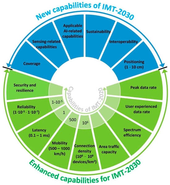
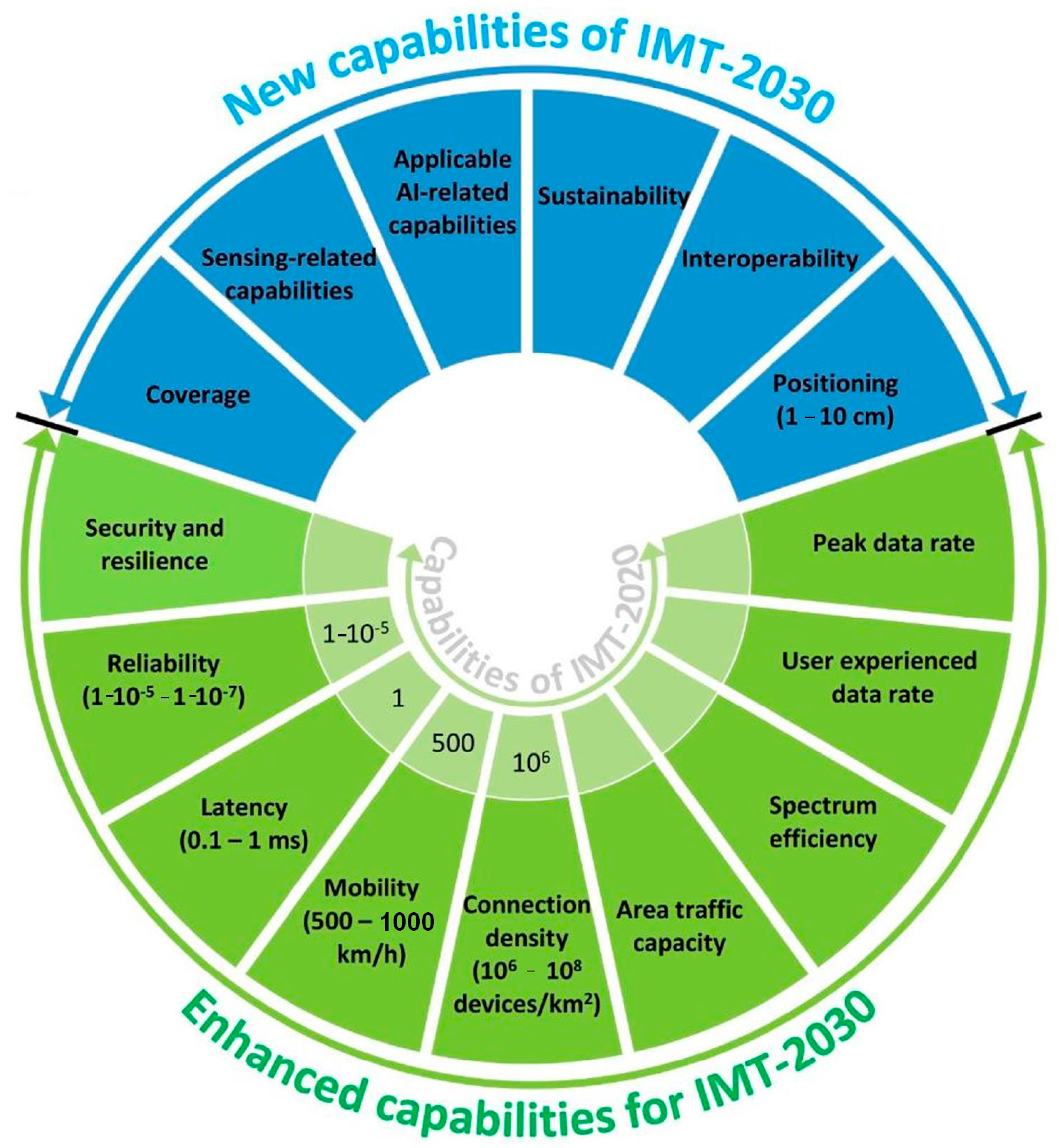
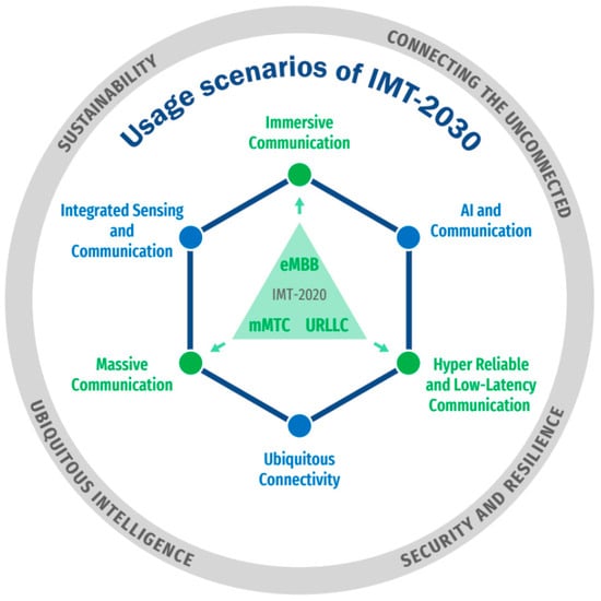
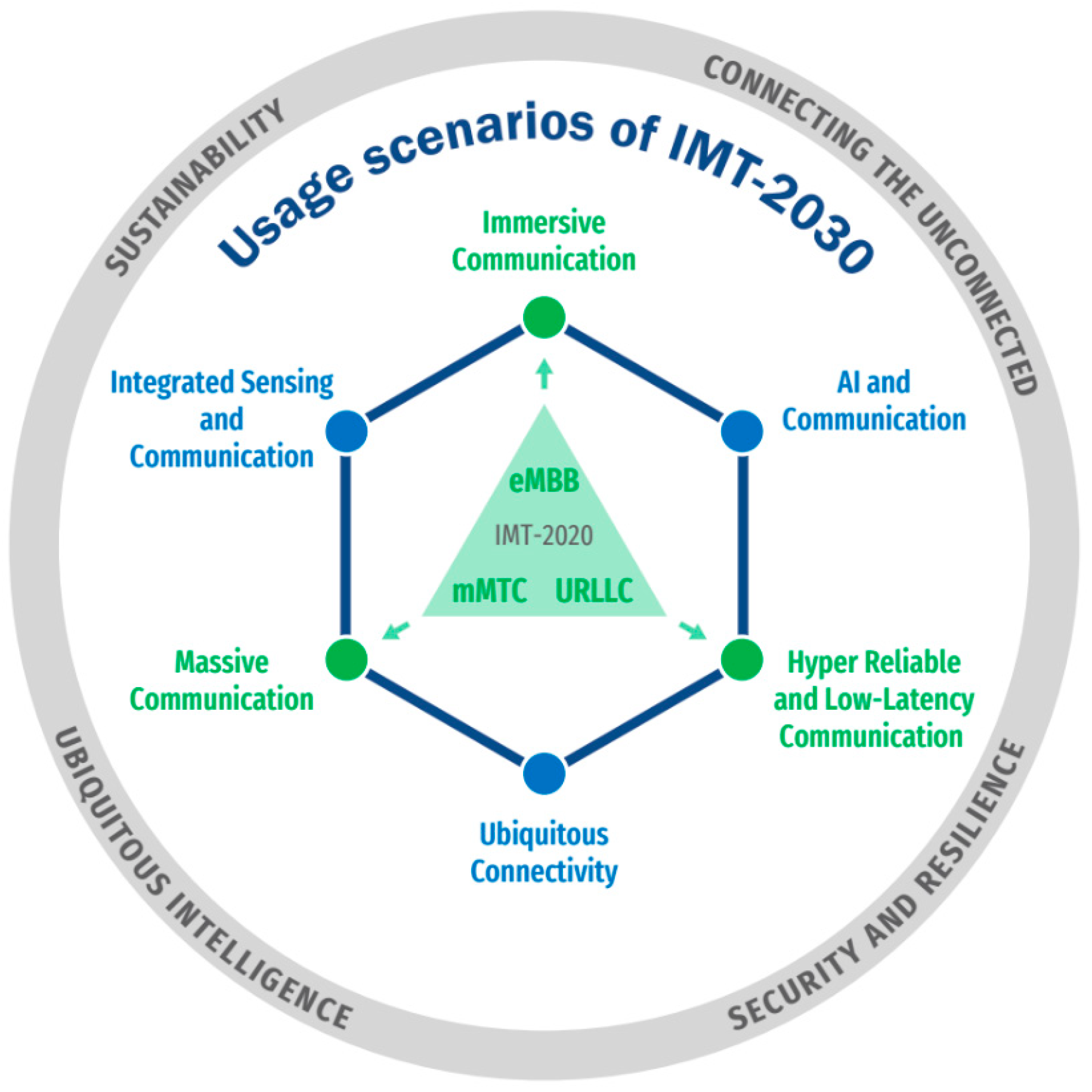
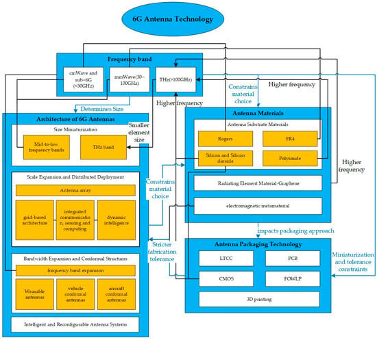
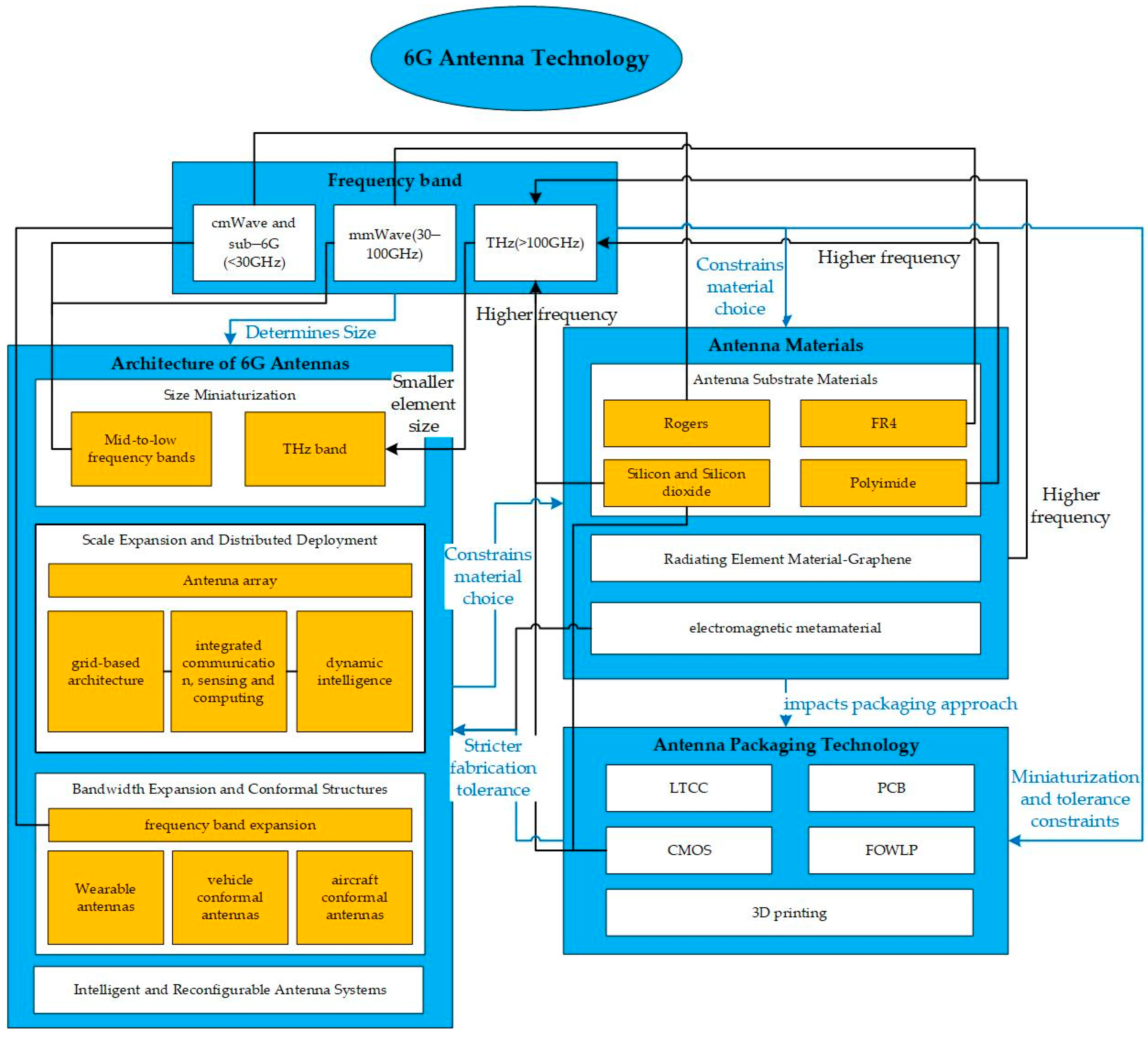
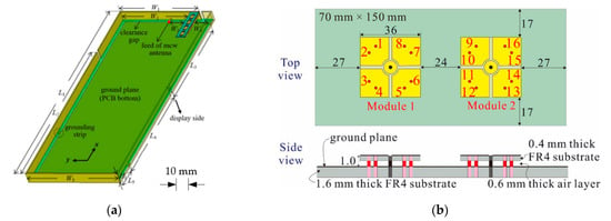
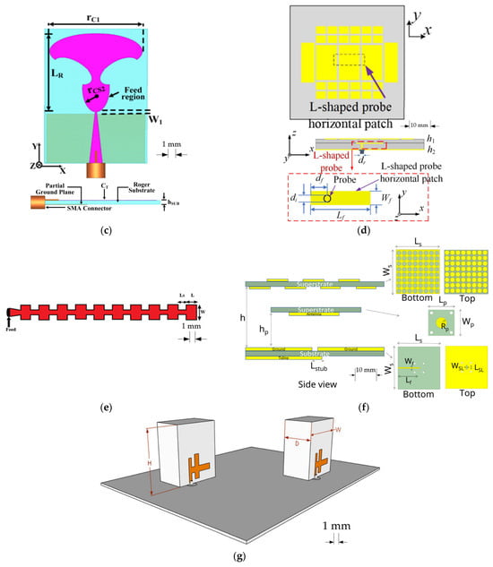
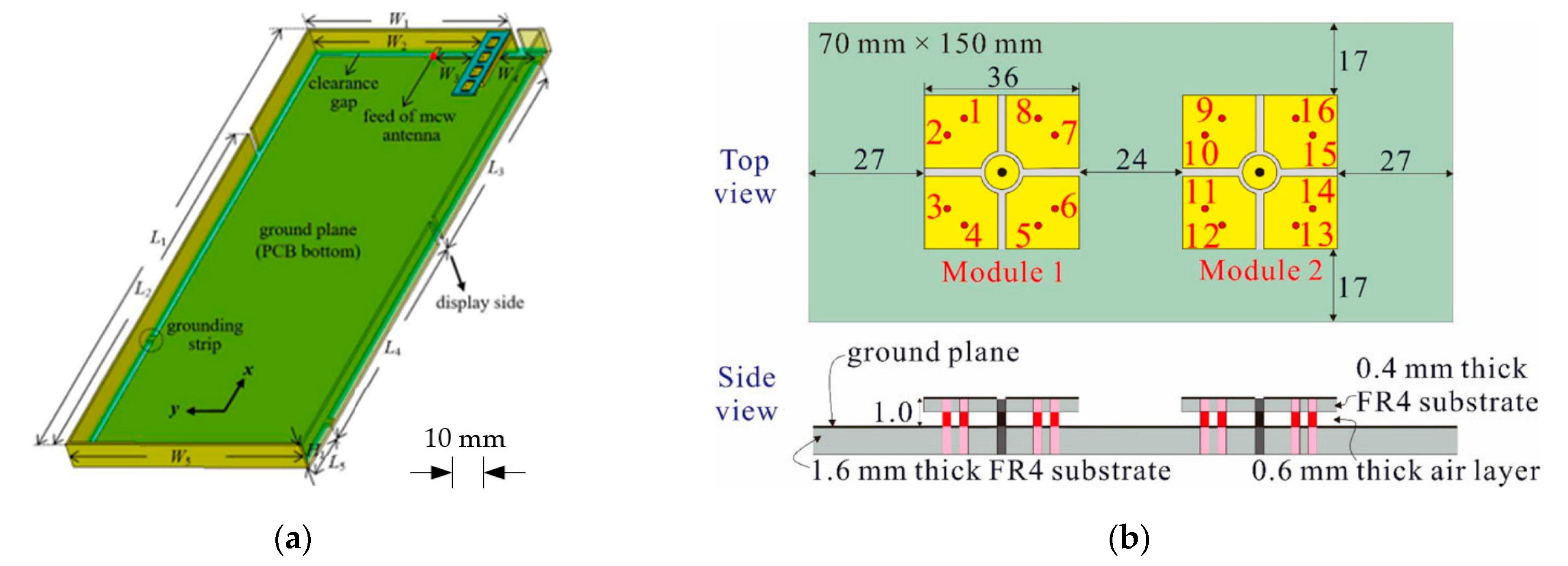
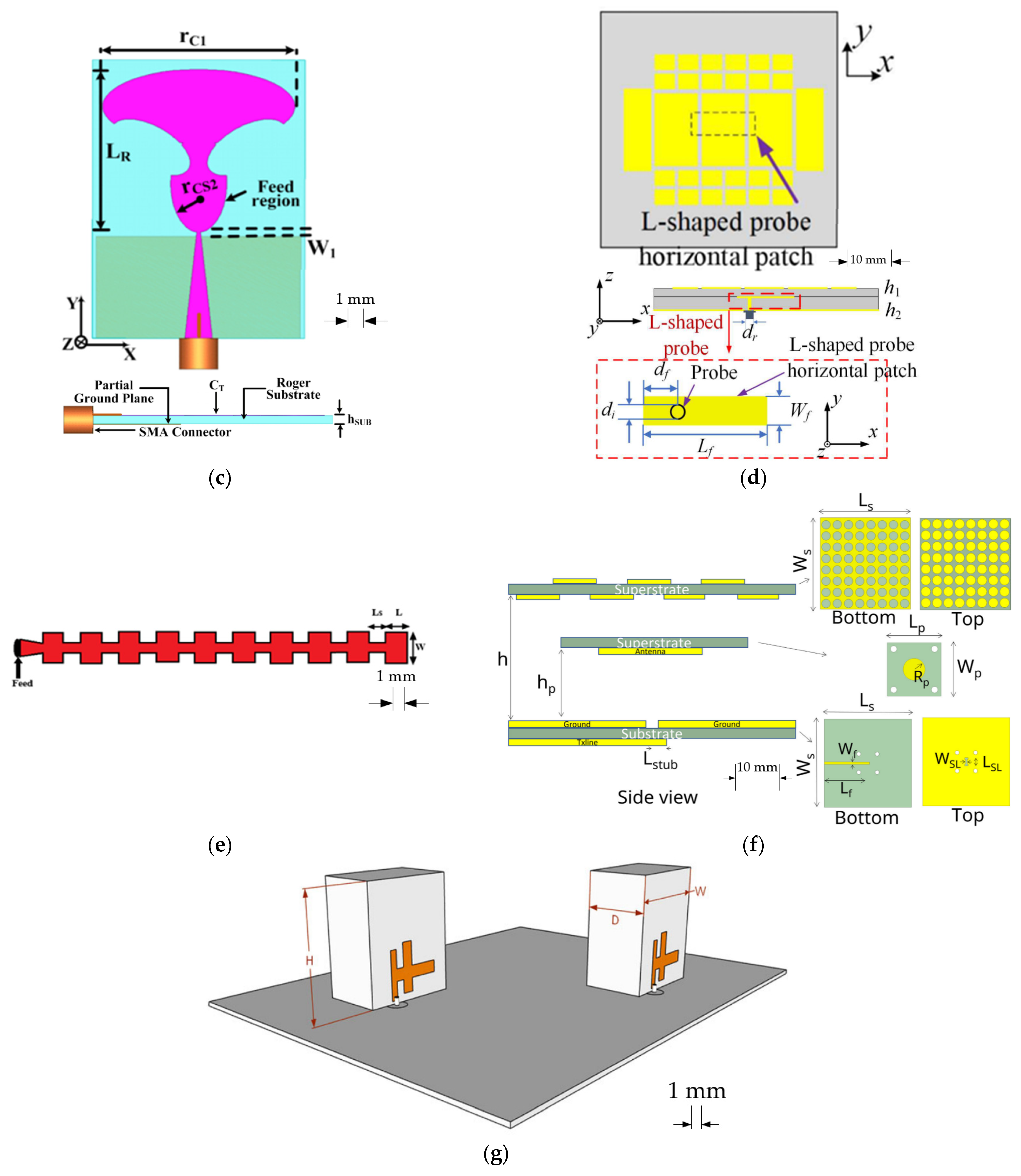
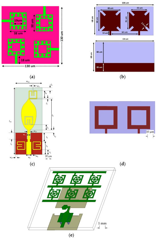
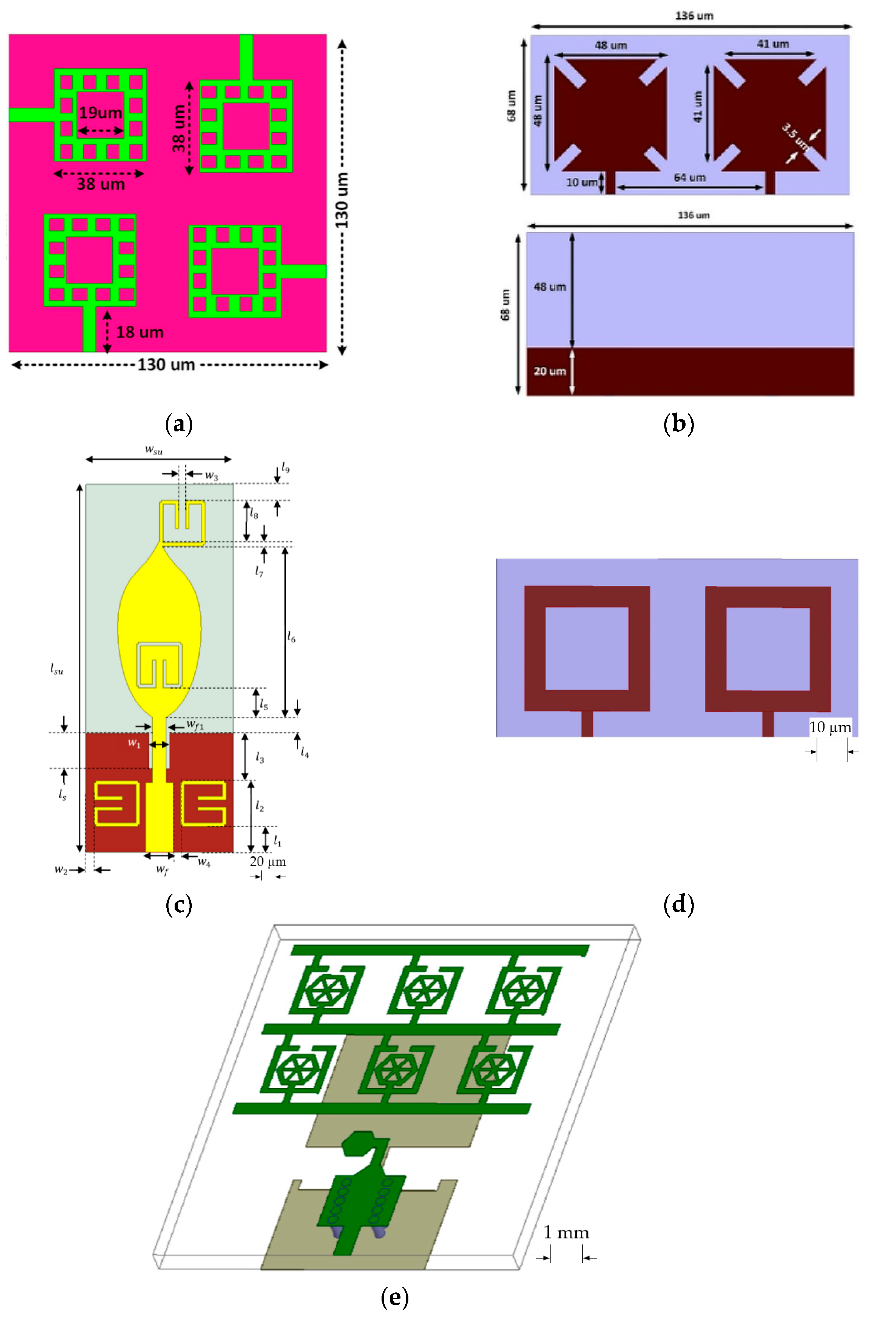
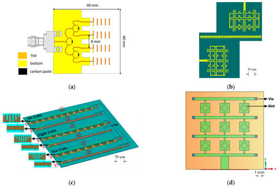
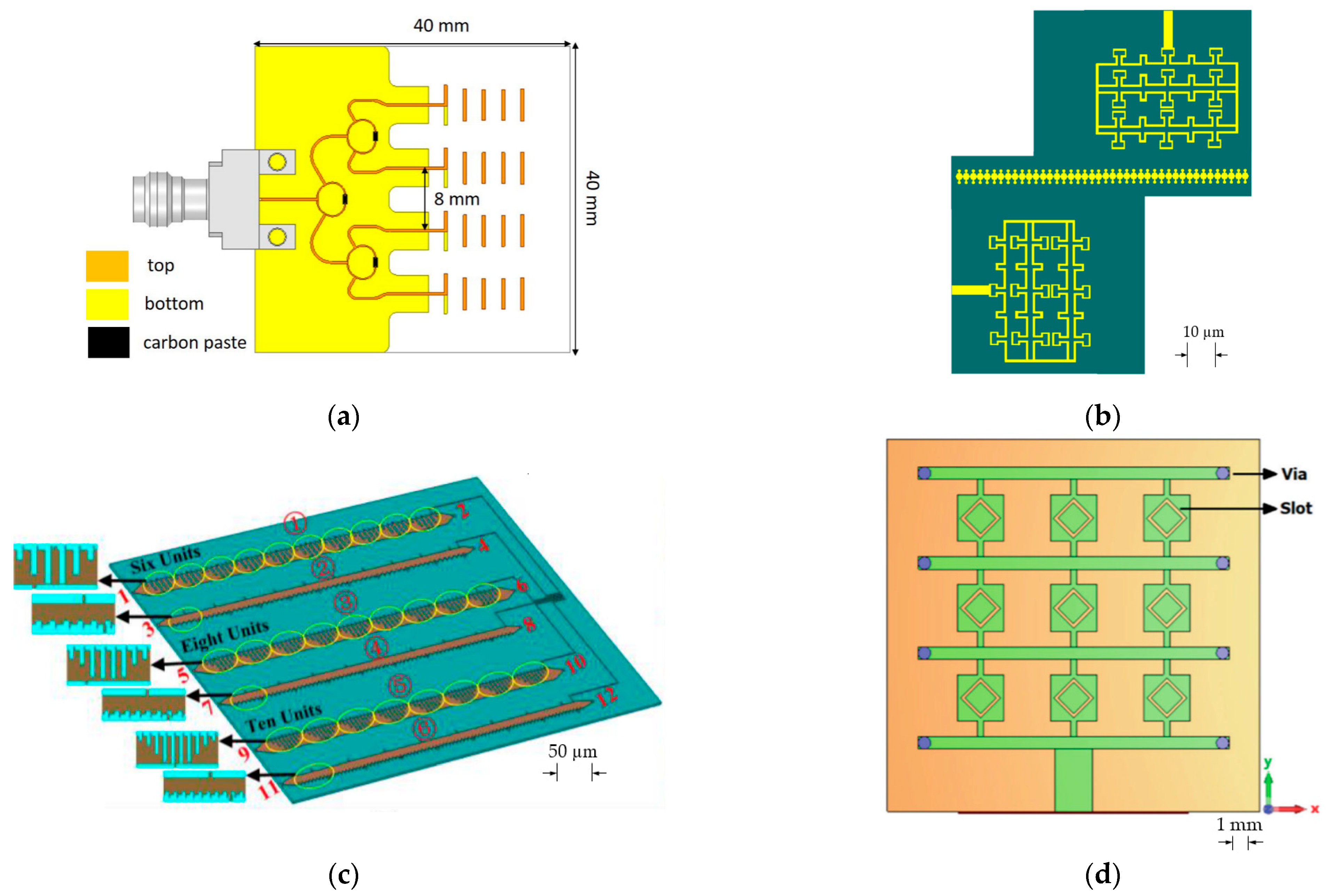
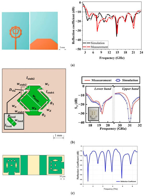
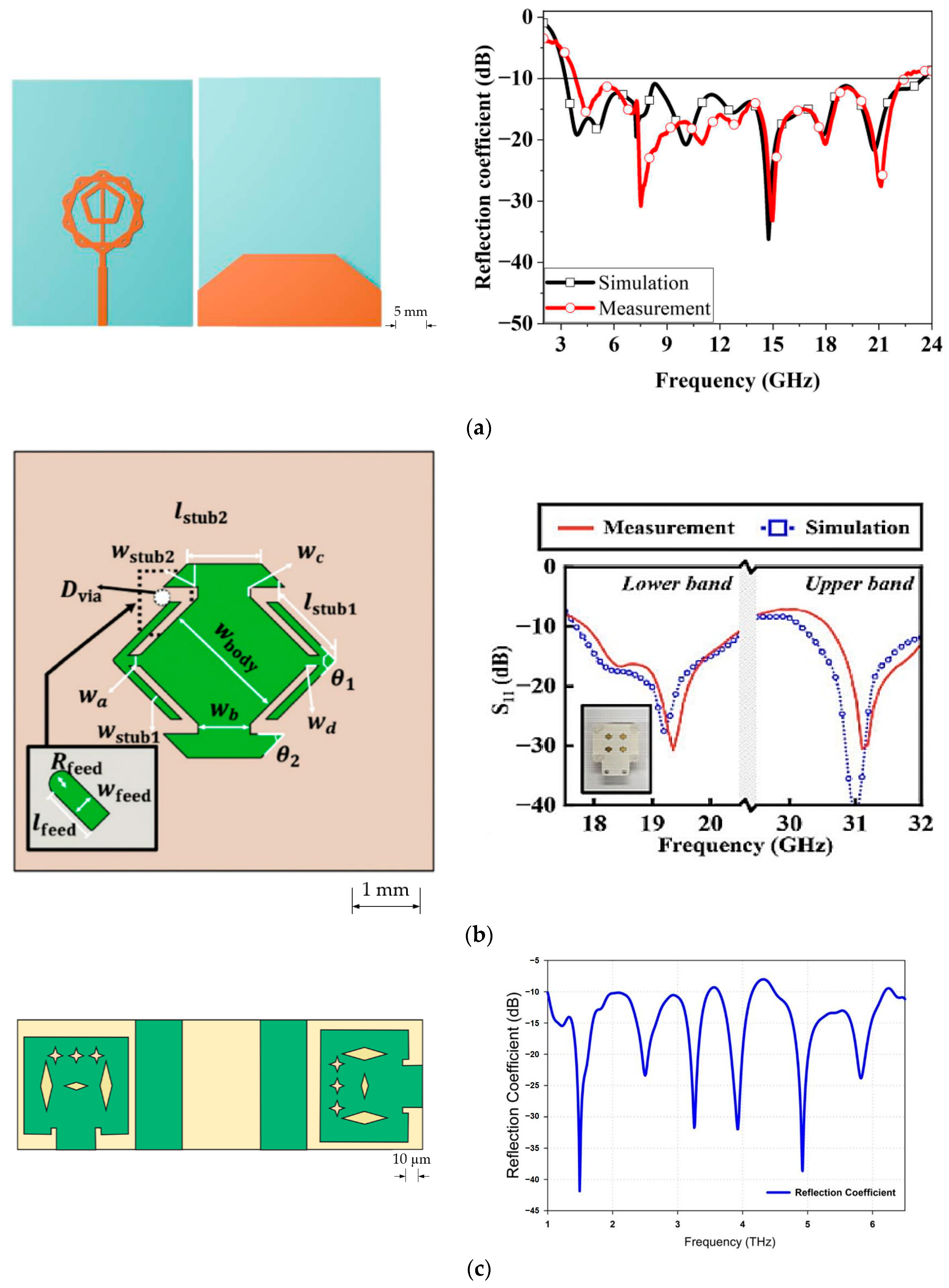
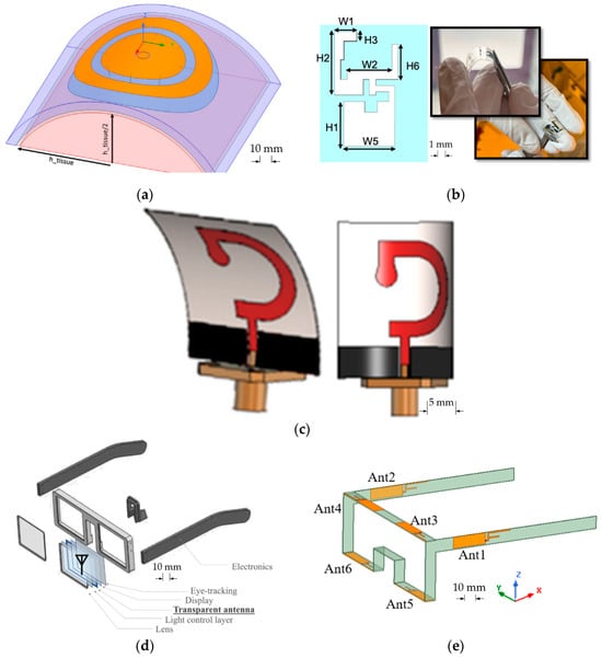
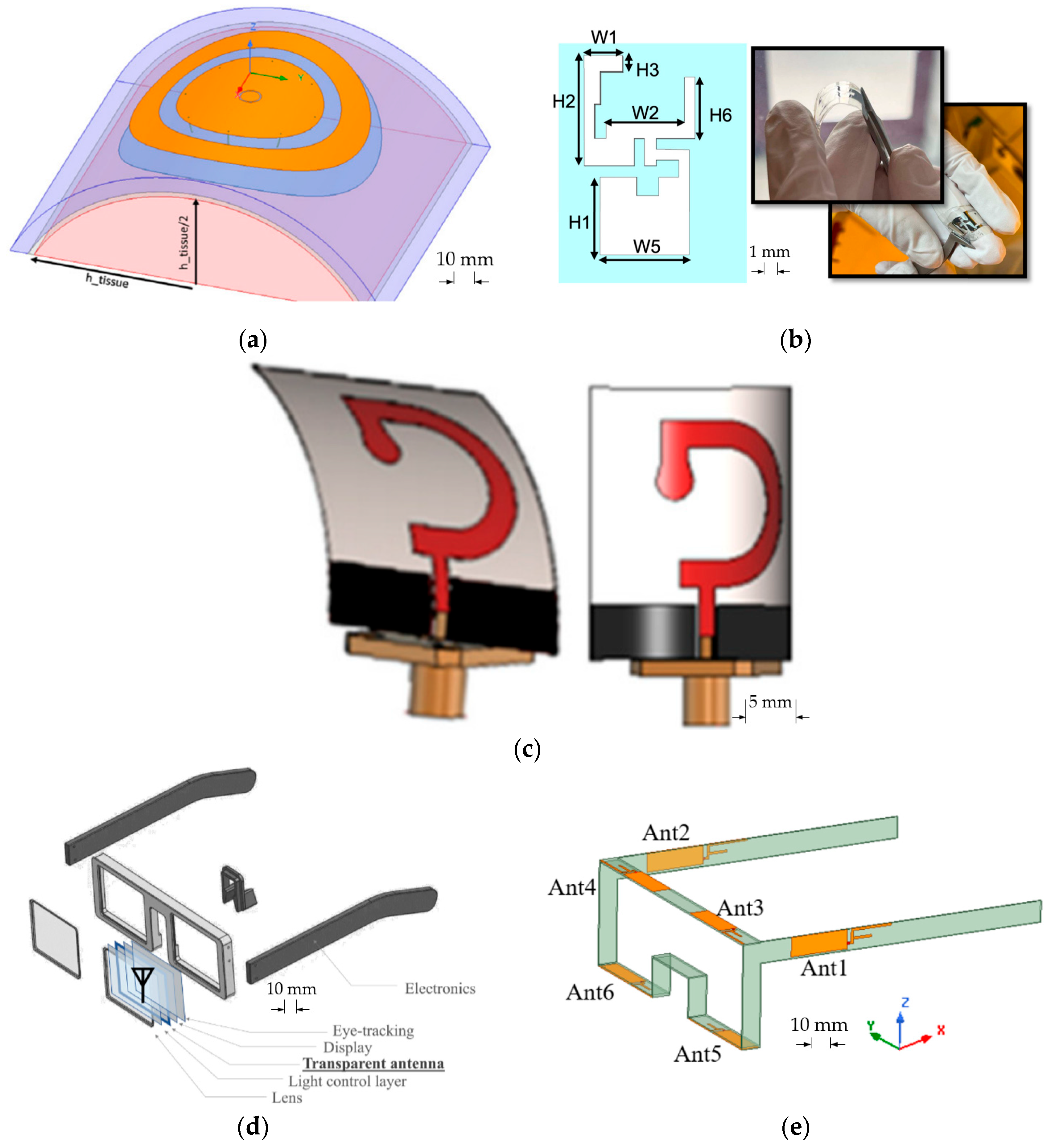
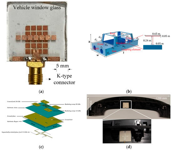
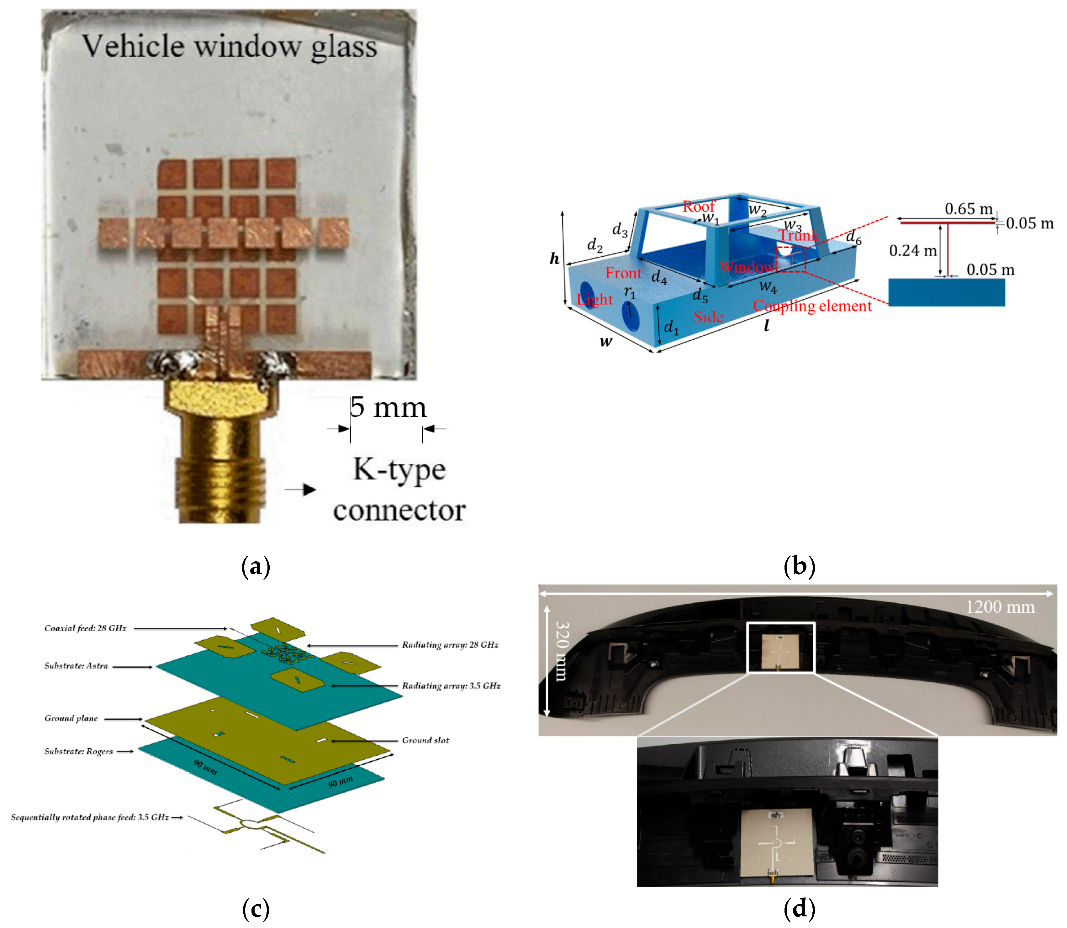
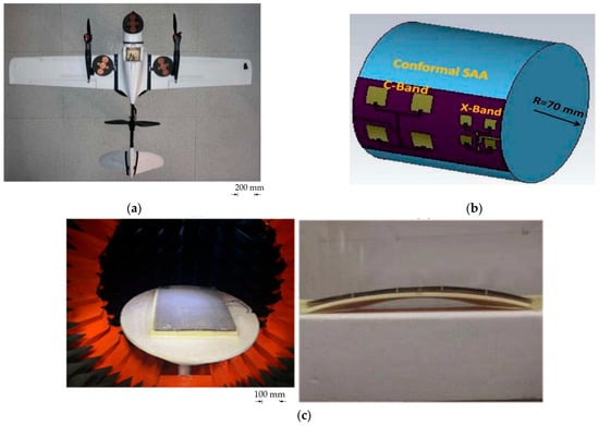
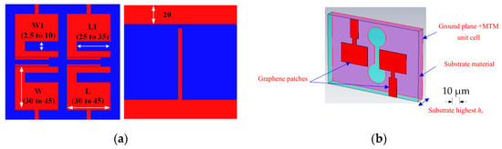
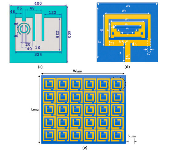
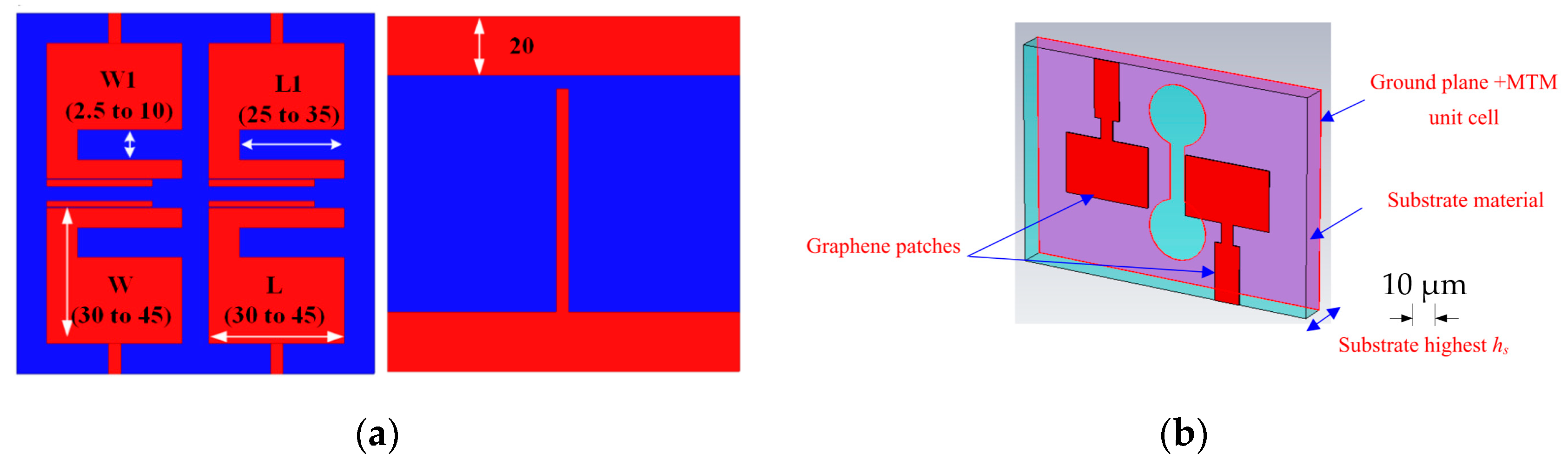
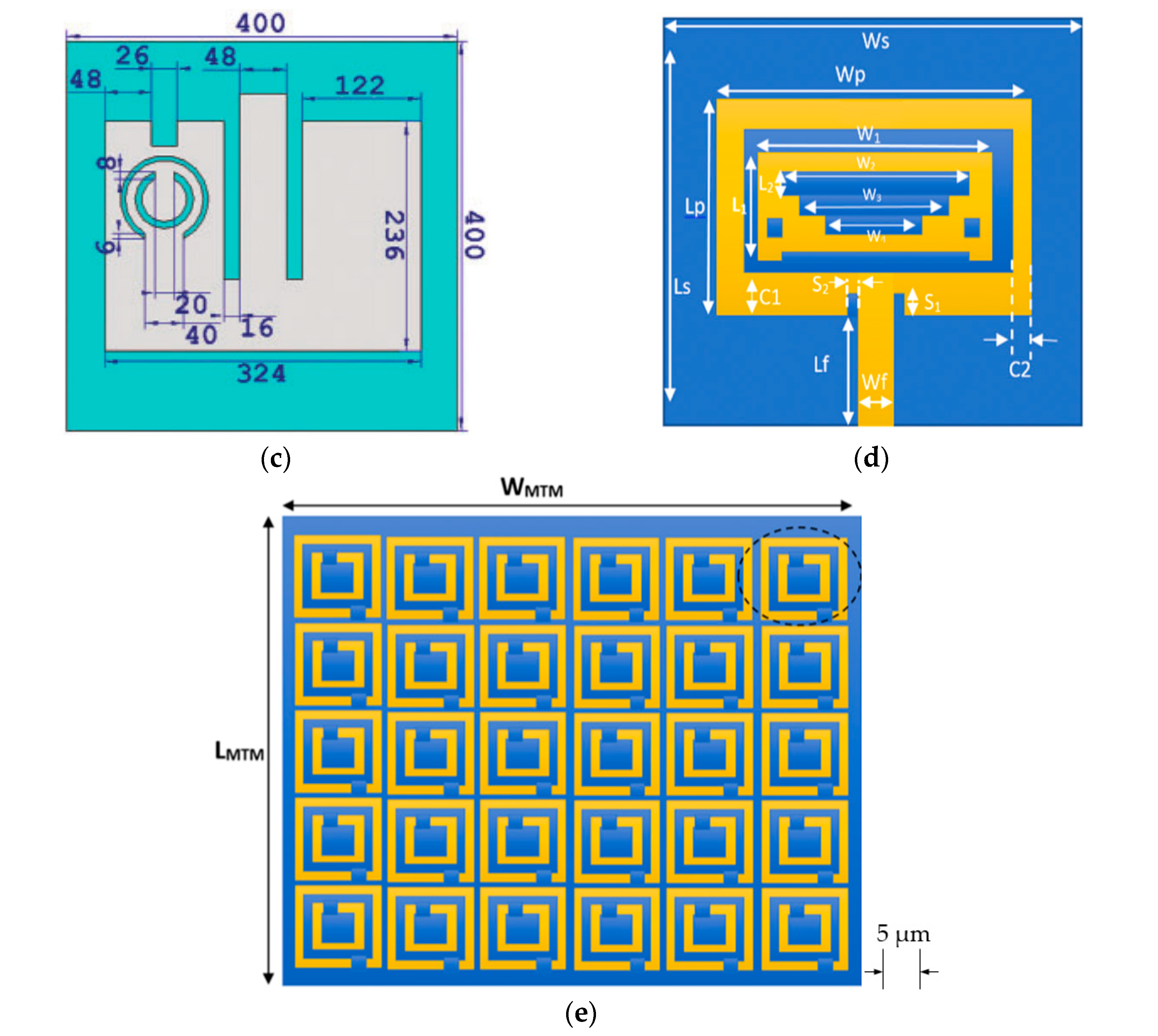
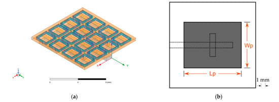
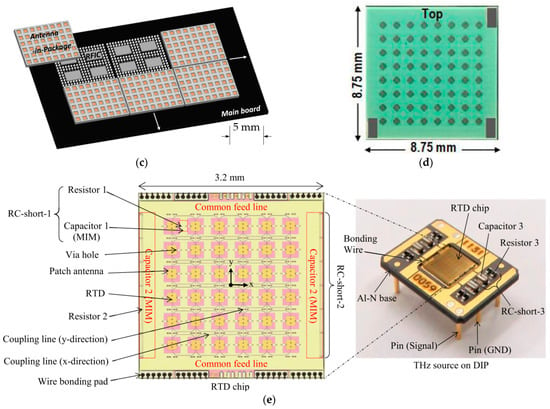
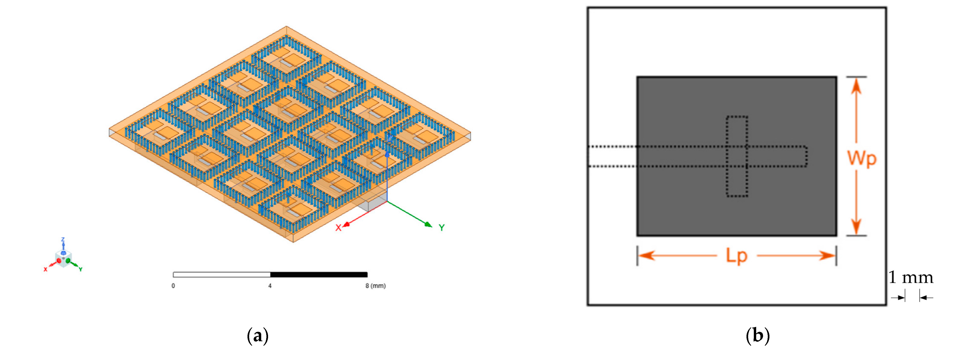
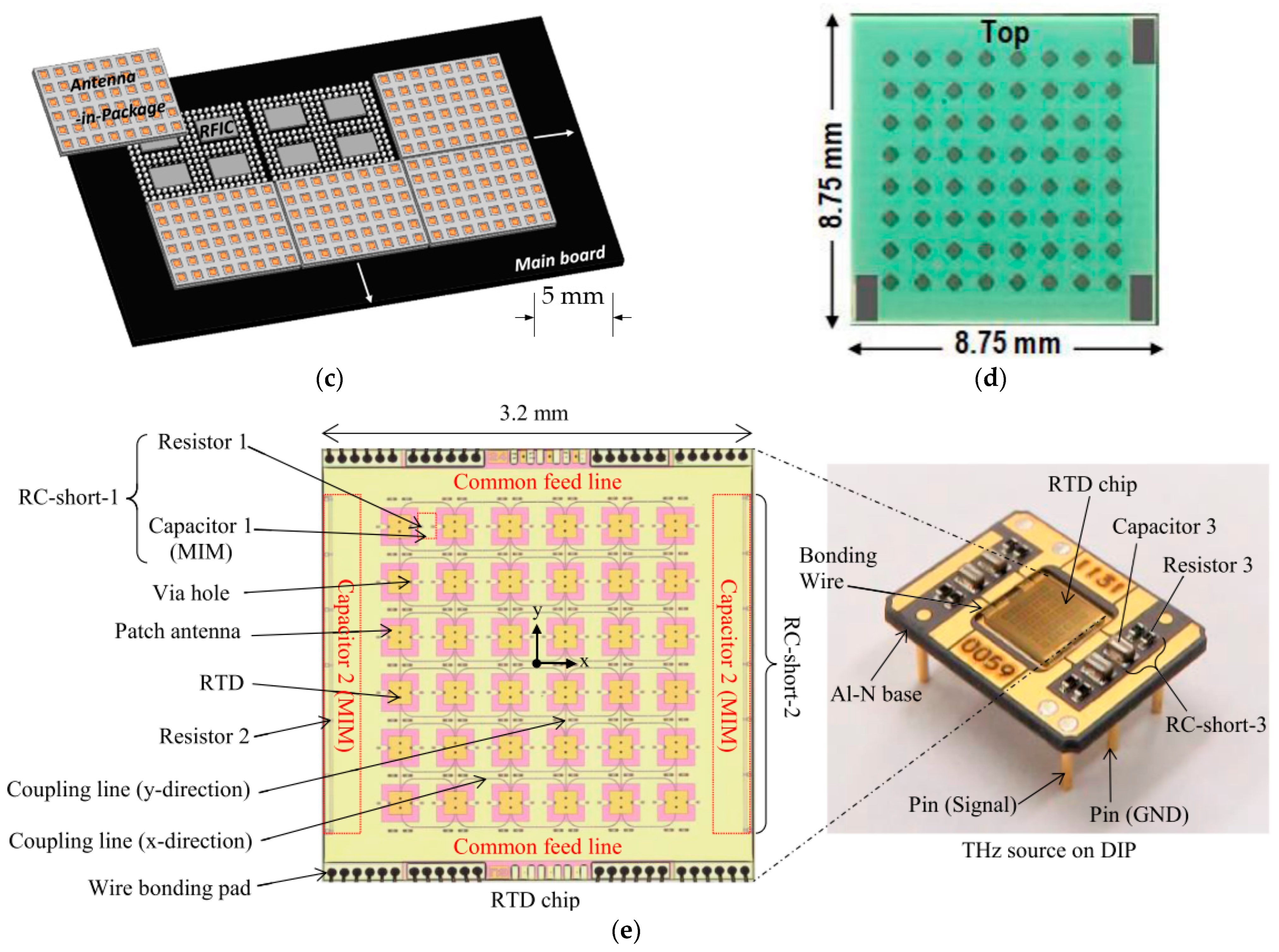
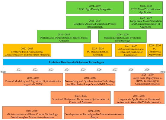
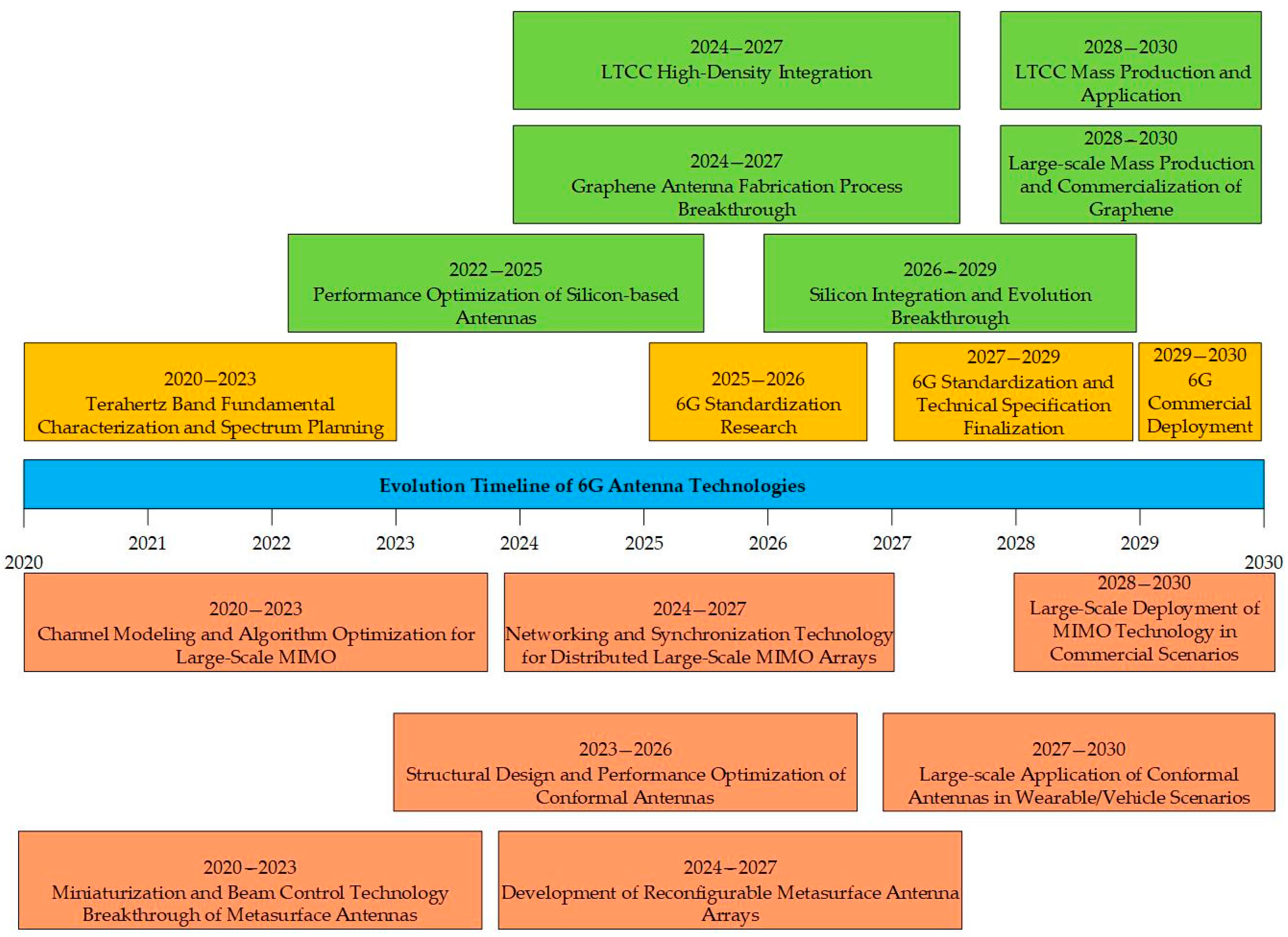

Disclaimer/Publisher’s Note: The statements, opinions and data contained in all publications are solely those of the individual author(s) and contributor(s) and not of MDPI and/or the editor(s). MDPI and/or the editor(s) disclaim responsibility for any injury to people or property resulting from any ideas, methods, instructions or products referred to in the content. |
© 2026 by the authors. Licensee MDPI, Basel, Switzerland. This article is an open access article distributed under the terms and conditions of the Creative Commons Attribution (CC BY) license.