


Abstract
This paper reports a magnetically tunable U-band metallic waveguide isolator based on the ferromagnetic resonance (FMR) absorption effect. The device features a BaFe12O19 (BaM) single-crystal array integrated into a rectangular waveguide. By leveraging the high intrinsic magnetocrystalline anisotropy and narrow FMR linewidth of the single-crystal material, the isolator achieves high-frequency operation with a significantly reduced external bias field. Experimental results demonstrate a broad continuous tuning range from 50 GHz to 66 GHz. The device exhibits exceptional efficiency, with a typical insertion loss of less than 0.5 dB (minimum 0.24 dB) and an isolation exceeding 15 dB across the operating band. The cascaded array configuration ensures uniform magnetization and stable performance. This combination of ultra-low insertion loss and frequency agility makes the proposed isolator an ideal candidate for next-generation adaptive millimeter-wave communication and radar systems.
1. Introduction
Microwave and millimeter-wave isolators are fundamental nonreciprocal components in modern electromagnetic communication systems. They play a crucial role in maintaining the stable operation of signal sources by permitting wave propagation in only one direction while effectively suppressing reverse transmission [1,2]. Among various types of microwave isolators, the most common ones mainly include the Faraday rotation-based transmission isolators [3,4,5], circulator-type absorption isolators [6,7], and ferromagnetic resonance (FMR) absorption-based isolators [8,9]. Faraday rotation-based transmission isolators offer relatively wide operational bandwidth; however, their implementation at sub-terahertz frequencies faces substantial fabrication challenges. The miniaturization of ferrite and alumina components demands extremely precise alignment to ensure optimal performance. Furthermore, the performance of such isolators is constrained by their dependence on a static magnetic bias field, which limits their applicability in systems requiring frequency agility [10,11].
Circulator-type absorption isolators typically adopt a structure similar to circulators, achieving unidirectional transmission through the absorption of electromagnetic waves at a third port. However, their operational frequency is inherently constrained by the fixed magnetic bias configuration [12]. To overcome these challenges, magnetically tunable isolators utilizing the FMR absorption effect present a promising solution, offering reconfigurable isolation. The origins of this work can be traced back to 1954, when A. G. Fox et al. systematically analyzed the nonreciprocal properties of ferrite materials at microwave frequencies. They discussed the nonreciprocal phase shift and absorption characteristics of ferrite-loaded waveguides and proposed the fundamental principles for constructing nonreciprocal components such as isolators and circulators [13]. By varying the external magnetic field, the resonance frequency and absorption bandwidth can be dynamically adjusted, providing greater flexibility in tuning isolation performance within a specific operational frequency range. This adaptive mechanism opens new opportunities for implementing intelligent microwave components in future high-frequency systems [14,15].
Magnetically tunable isolators in the U-band (40–60 GHz) are scarce due to key challenges, including the difficulty of providing a strong bias magnetic field, increased dielectric and insertion losses at high frequencies, and ferrite linewidth broadening. These factors lead to reduced resonance efficiency and make achieving both high resonance efficiency and low insertion loss a significant challenge [16]. In 2007, Capraro et al. proposed an integrated, self-biased coplanar isolator using BaFe12O19 (BaM) films, demonstrating its potential for high-frequency applications. However, their work encountered significant limitations, including high insertion losses and weak isolation performance, with insertion losses reaching up to 18 dB at 50 GHz [17]. In Li’s 2015 dissertation on 60 GHz resonance isolators, the performance of the device was significantly affected by high insertion loss, with single-side ferrite strip isolators showing losses up to −8 dB. Despite the use of BaM thin films and an H-plane resonance structure, the insertion loss remained considerable, which limits the device’s performance in high-frequency applications [18]. To address these issues, this study presents a U-band isolator that uses BaM single-crystal material. The high magnetocrystalline anisotropy of BaM allows efficient resonance with a relatively low external bias field, while the narrow FMR linewidth of the single crystal ensures very low insertion loss.
Additionally, strong coupling between the waveguide mode and the ferromagnetic medium is essential for achieving stable and tunable isolation. In conventional designs, the entire ferrite ferrimagnetic sheet is inserted into the waveguide. However, large ferrite pieces tend to cause uneven magnetization, which results in higher-order mode interference, thereby worsening the insertion loss. On the other hand, reducing the size of the ferrite pieces weakens the FMR absorption effect, which in turn leads to insufficient isolation performance of the device [19,20].
To address these challenges, this work proposes a fundamentally different approach: a cascaded BaM single-crystal array. By segmenting the material into an optimized array, we achieve a highly uniform internal magnetic field and suppressed parasitic resonances. To the best of our knowledge, this is the first report of a U-band isolator utilizing a cascaded single-crystal array architecture, demonstrating a record-low insertion loss of −0.24 dB and a broad tuning range of 50–66 GHz. This design not only declares a new performance benchmark but also provides a robust physical solution for low-loss, frequency-agile millimeter-wave systems.
2. Operation Principle of Isolator
A linearly polarized electromagnetic wave can be decomposed into two circularly polarized fields of the same frequency with the same amplitude and opposite rotation direction, which can be expressed as
Based on the relationship between the magnetization m and h, it can be derived that [21]
The following can be obtained:
Split the real part and imaginary part as follows:
When ω = ω0, and (ω0 − ω)2 + (αω)2 are very small values, μ+ reaches a maximum value, which produces a strong FMR absorption for the right-hand circularly polarized component h+. However, μ- is very small and far from the resonance range, so the left-handed component is hardly absorbed [22].
It should be noted that unlike optical frequencies where μ ≈ 1 and ñ ≈ (ε)1/2, BaM ferrite in the U-band (40–60 GHz) exhibits a strong gyromagnetic response. In this regime, spin magnetization effectively interacts with the field, resulting in a dispersive complex permeability tensor μ that enables nonreciprocal isolation. Additionally, as the U-band is far below dielectric relaxation frequencies, εr is treated as a constant scalar.
Suppose that the shape of the rectangular waveguide is as follows: wide side a (x-direction), narrow side b (y-direction), and the electromagnetic wave propagation direction is the z-direction.
The field distribution of the main mode is as follows:
The magnetic field component can be obtained from the Maxwell equation:
The magnetic field at point x0 is a time-varying vector, which can be expressed as
The field vector rotates along an ellipse in the x-z plane, becoming circular only at specific positions.
Define the circularly polarized component of TE10 mode at x0:
Substitute Equation (6) into Equation (8):
For the dominant TE10 mode, the propagation constant β satisfies
If H+(xA) = 0, then only H− exists at the xA point, resulting in pure left-handed circular polarization.
If H−(xB) = 0, then only H+ exists at the xB point, resulting in pure right-handed circular polarization.
Solve for the positions of the circular polarization points:
- For H+(xA) = 0:
- For H−(xB) = 0:
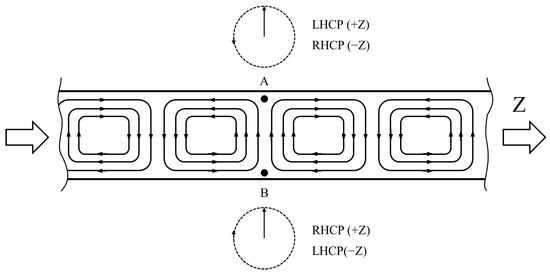
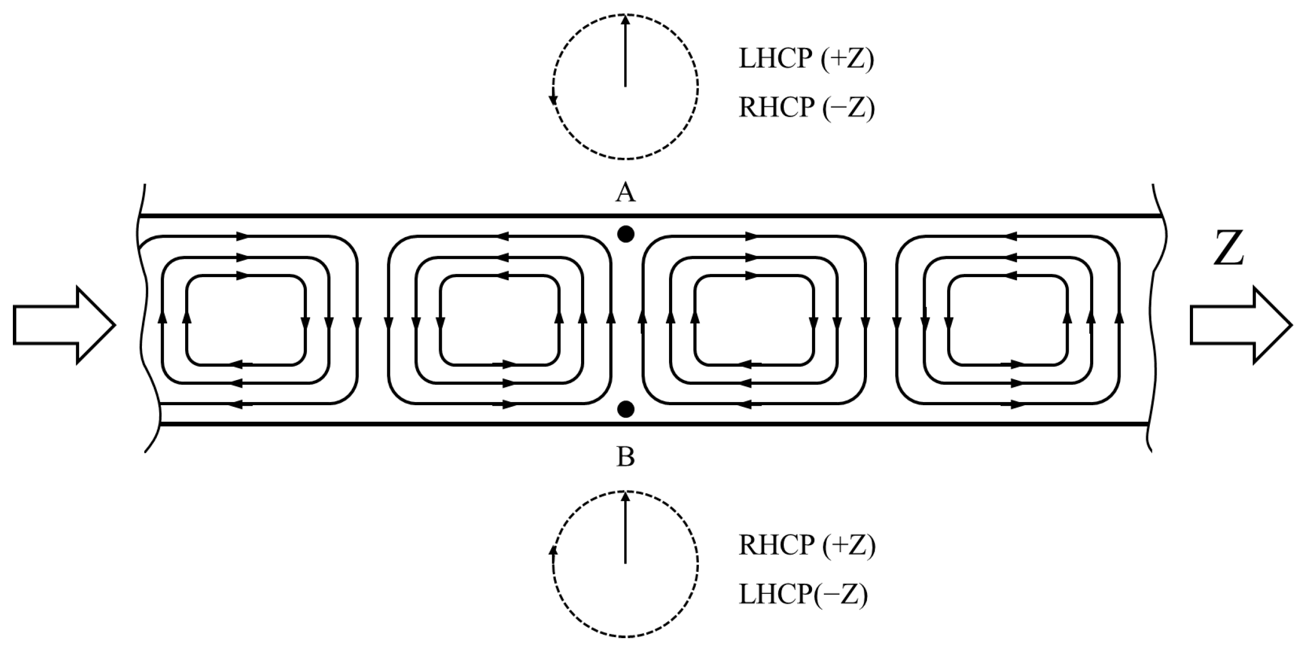
It is established that at point A only a left-handed circularly polarized (LHCP) wave exists, whereas point B exclusively supports a right-handed circularly polarized (RHCP) wave (as shown in Figure 1). By placing a biased ferrite at either point, forward-propagating microwaves experience the polarization state that is not absorbed by the ferrite, enabling low-loss transmission. In contrast, under reverse propagation, the effective handedness becomes the one strongly absorbed by the ferrite, leading to rapid energy attenuation and thus preventing significant signal reflection toward the input. This mechanism effectively realizes unidirectional transmission isolation [23,24].
Figure 1.
TE10 mode field distribution in a rectangular waveguide.
3. FMR Linewidth of Material
The FMR linewidth exerts a critical influence on isolator performance. While a broader linewidth can enhance isolation, it simultaneously leads to increased insertion loss. In this study, the BaM single crystal is employed as the core material for fabricating the isolator. Compared to polycrystalline and thin-film materials, the BaM single crystal exhibits a significantly narrower FMR linewidth, which enables a substantial reduction in the insertion loss of the device. Furthermore, this single crystal possesses a high magnetocrystalline anisotropy field about 17 kOe [25]. This property allows the FMR absorption to be achieved under a relatively small external bias field (e.g., ~2 kOe), which is significantly lower than the field required by low-anisotropy ferrites (such as YIG) to reach resonance at the same U-band frequencies. It is noteworthy that the BaM single crystals used in this work were grown independently by the liquid-phase epitaxy (LPE) method. The specific growth process can be found in our previous research [26].
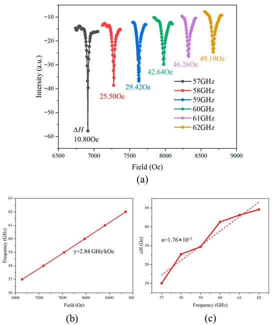
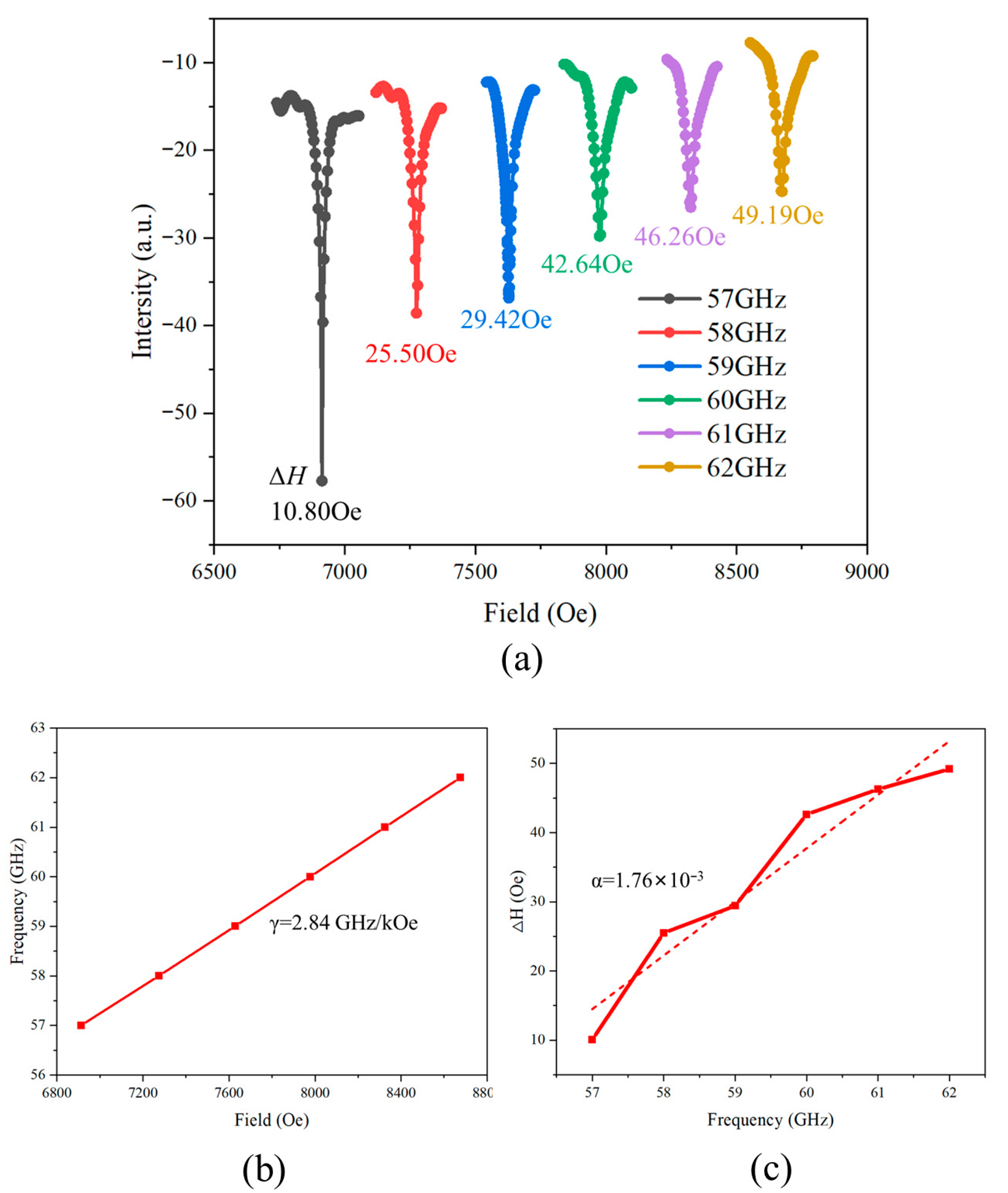
Figure 2a presents the FMR absorption spectra of BaM single crystal in the frequency range of 57~62 GHz. It is evident that the sample exhibits an extremely narrow FMR linewidth. At 57 GHz, the linewidth is only 10.80 Oe, and it gradually increases with frequency, finally rising to the maximum value of 49.19 Oe at 62 GHz. At each frequency, the absorption curves exhibit symmetric and sharply defined resonance peaks, indicating a highly uniform magnetic resonance response. In addition, the peak shapes remain well preserved and free of distortion as the magnetic field increases, further confirming the excellent magnetic homogeneity and low defect density of the BaM single crystal. Furthermore, by fitting the linear relationship between the resonance frequency and resonance field, the gyromagnetic ratio is determined to be
which agrees well with the typical values reported, confirming that the magnetic anisotropy field and internal exchange interactions of the sample are in an ideal state [27,28]. Meanwhile, fitting the linewidth ΔH as a function of frequency yields a damping coefficient of
which is significantly lower than that of polycrystalline. This result indicates that the single crystal possesses very low magnetic loss and a slow magnetization relaxation process, both of which are beneficial for minimizing the additional attenuation in isolator applications.
Figure 2.
(a) Ferromagnetic resonance absorption spectrum of the BaM single crystal. (b) Linear relationship between resonance frequency and resonance field. (c) Dependence of FMR linewidth ΔH on frequency f.
4. Simulation and Analysis
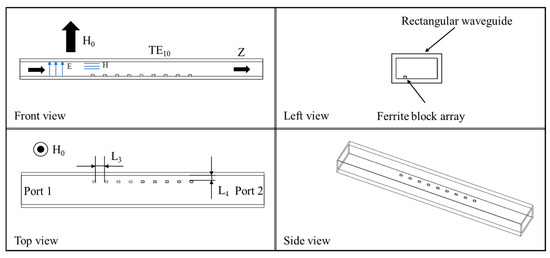
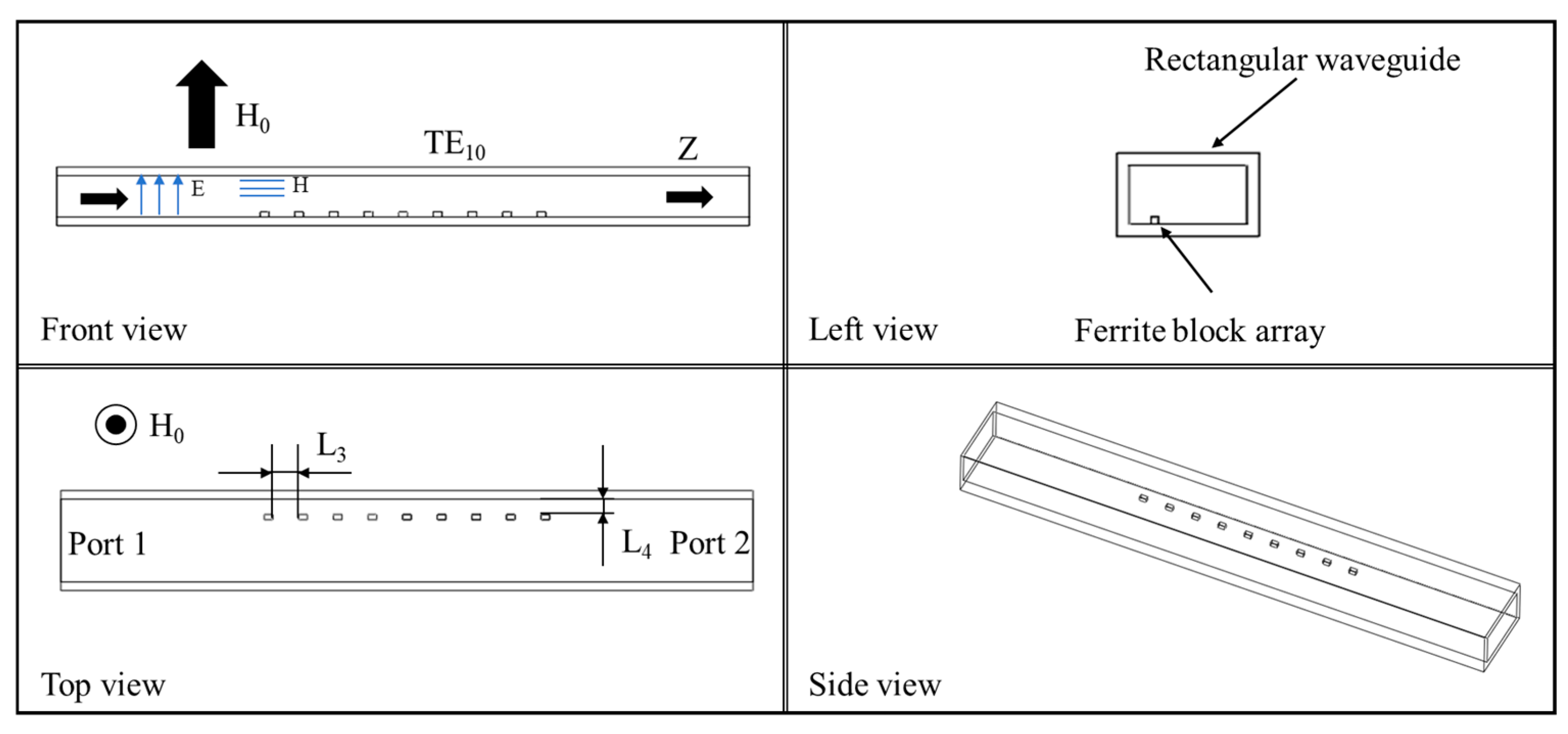
All simulations are conducted in Ansys HFSS 2019. The proposed isolator structure is shown in Figure 3. The device consists of a WR18 (4.775 × 2.388 mm) rectangular waveguide loaded with a linear array of nine BaM blocks. Each BaM element is a rectangle measuring L1 × L2 × h1 = 0.5 × 0.3 × 0.3 mm3, which is uniformly bonded to the broad wall (H-plane) of the waveguide using a thin conductive adhesive layer. The BaM blocks are arranged along the longitudinal propagation direction of the waveguide, forming a periodic loading structure. The spacing between adjacent blocks is defined as L3, which is kept constant across the array. In addition, the distance between the BaM block and the waveguide boundary is denoted as L4. These parameters determine the resonance coupling strength, and the resulting nonreciprocal attenuation induced by the BaM. This array-based loading approach enhances the interaction between the electromagnetic field and the ferrite blocks, enabling strong FMR absorption.
Figure 3.
Structure of the designed device from multiple viewing angles.
In this work, H0 is applied perpendicular to the H-plane of the waveguide to satisfy the coupling condition for FMR absorption effect. The BaM single crystal is oriented with its crystallographic c-axis aligned parallel to H0, capitalizing on the material’s strong uniaxial magnetocrystalline anisotropy along this direction. This configuration maximizes the utilization of the intrinsic anisotropy field, enabling a higher FMR frequency under a relatively low H0. Such a feature is particularly advantageous for millimeter-wave isolators, as it ensures stable high-frequency operation while maintaining a compact bias magnet system. The key magnetic parameters of the BaM crystal are summarized in Table 1.
Table 1.
BaM single-crystal ferrite parameters.
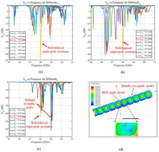
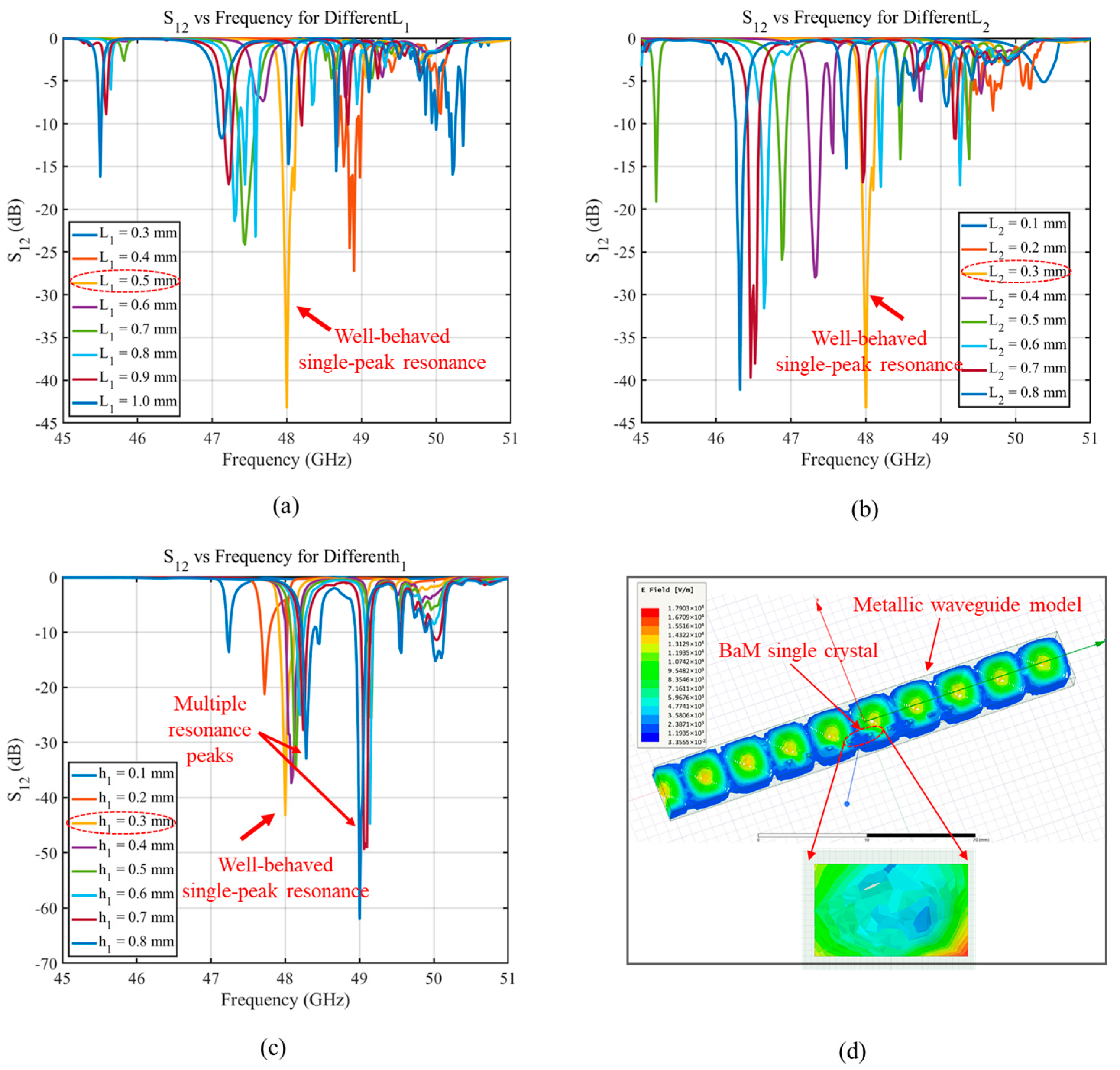
Figure 4a–c illustrate the simulated S12 responses for different ferrite dimensions, while Figure 4d presents the electric field distributions within the metallic waveguide. For small ferrite dimensions, the effective interaction volume between the electromagnetic field and the ferrite is limited, leading to a relatively weak FMR absorption. This results in shallow resonance dips and reduced isolation. As the ferrite size increases, the FMR absorption strengthens and yields a well-defined single resonance peak, which corresponds to the uniform precession of magnetic moments. This behavior is desirable for isolator operation, where a clean and strong resonance is necessary to achieve high reverse attenuation.
Figure 4.
Simulated S12 characteristics of the isolator under different ferrite dimensions and field distributions. (a) S12 vs. frequency for different L1; (b) S12 vs. frequency for different L2; (c) S12 vs. frequency for different h1; (d) electric field distribution in rectangular waveguide.
However, when the ferrite becomes excessively large, the field distribution inside the ferrite block becomes increasingly nonuniform, as shown in the zoomed-in field map in Figure 4d. The nonuniform field excitation promotes the formation of higher-order spin-wave modes in addition to the fundamental uniform FMR mode. These nonuniform spin-wave resonances lead to multiple resonance dips and a fragmented absorption spectrum. Consequently, the S12 curve exhibits multiple peaks and degraded isolation performance due to the coexistence of several competing precession modes, which disrupts the clean and selective resonance essential for isolator functionality.
The simulation results reveal that the ferrite dimension of 0.5 × 0.3 × 0.3 mm3 supports uniform magnetization precession, producing a clean single resonance dip in the S12 spectrum.
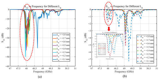
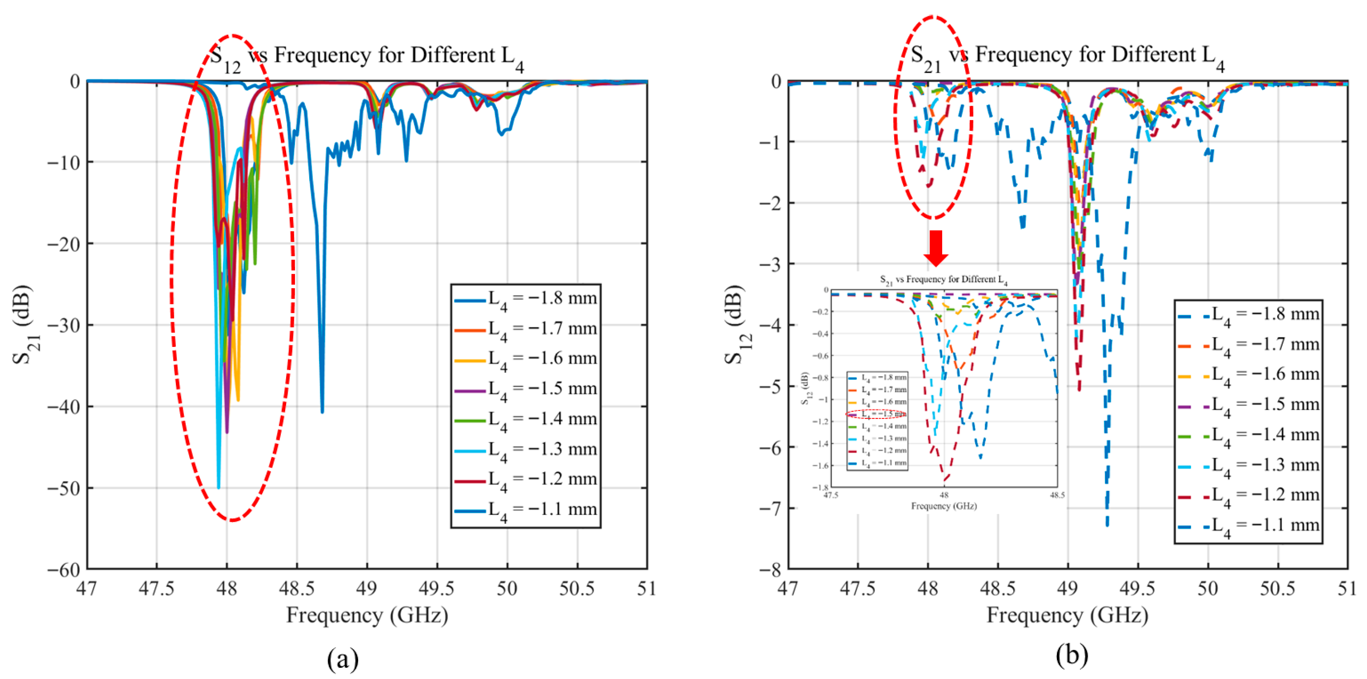
Figure 5 shows the simulated S21 and S12 responses of the isolator for different L4 values. As shown, each L4 value creates a distinct absorption dip in the S12 curve, indicating absorption of waves traveling in the reverse direction. However, S21 also shows resonance dips for most L4 values, suggesting that the ferrite is not positioned at the special circular-polarization points. When L4 = −1.5 mm, S21 shows minimal absorption, while S12 shows a strong absorption dip. This indicates that the ferrite is located at point A or B, where the wave contains only one type of circular polarization, allowing the ferrite to absorb only the reverse-propagating wave and enabling high isolation and nonreciprocal transmission.
Figure 5.
S21 and S12 versus frequency for different ferrite positions L4. (a) S12 vs. frequency for different L4; (b) S21 vs. frequency for different L4.
5. Fabricated Device Measurement Results
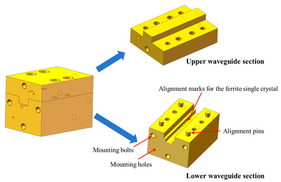
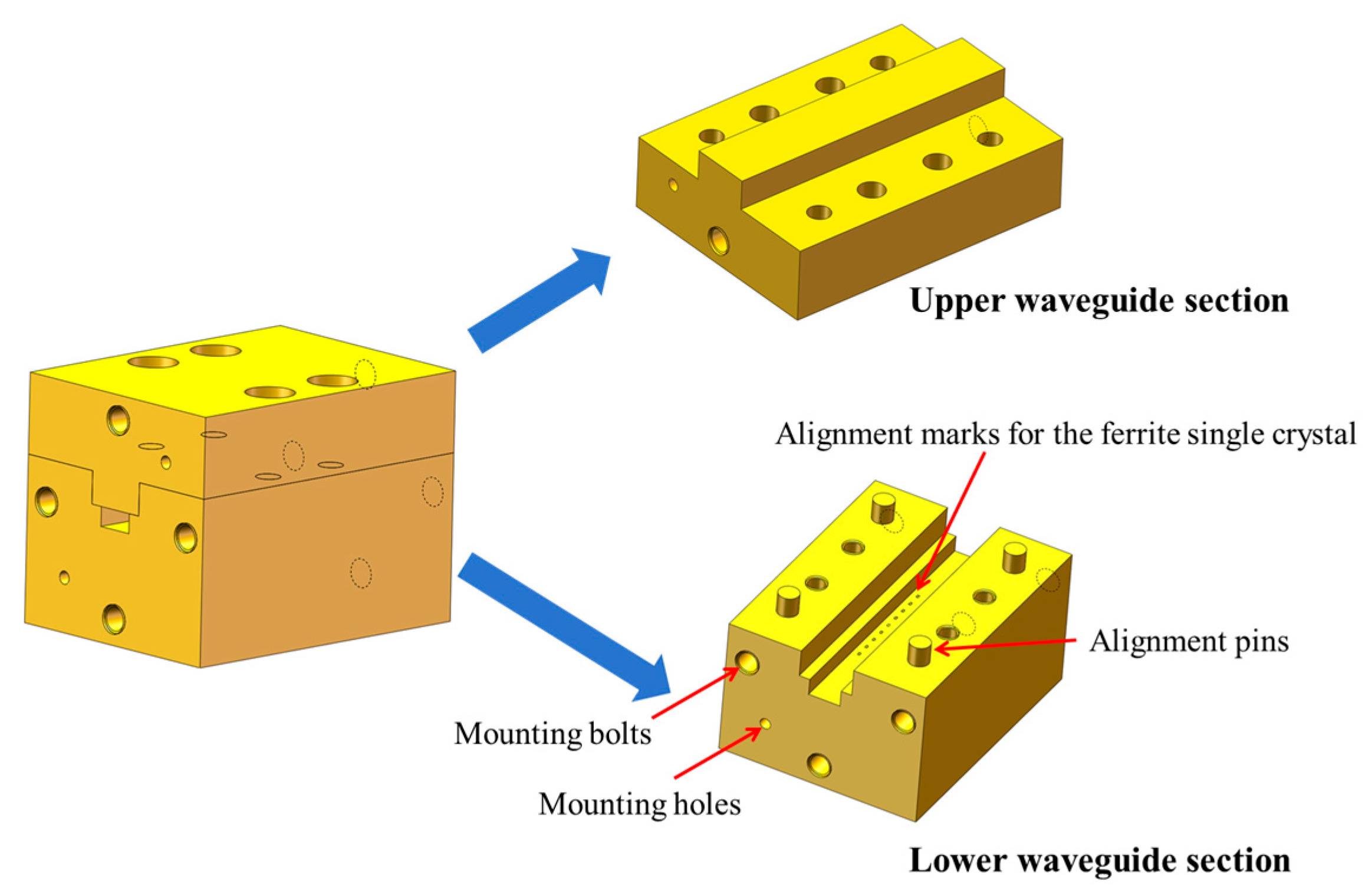
The isolator structure, shown in Figure 6, consists of an upper and lower housing, aligned with positioning dowel pins, and secured with bolts for mechanical stability and RF sealing. The waveguide cavity is machined as part of the lower housing, while the upper housing features a top-opening structure that covers the cavity. The contact area between the upper lid and lower body is minimized to reduce RF leakage. The opening interface is slightly larger than the waveguide’s broad wall, improving the electromagnetic seal and reducing sensitivity to surface flatness errors. Standard waveguide-to-coax adapters are mounted at both ends for easy connection to measurement equipment. Alignment markers inside the cavity guide the precise placement of the BaM single-crystal array, ensuring consistency during assembly.
Figure 6.
Schematic of the designed isolator.
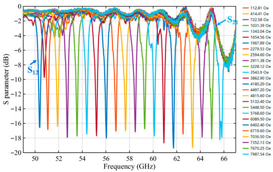
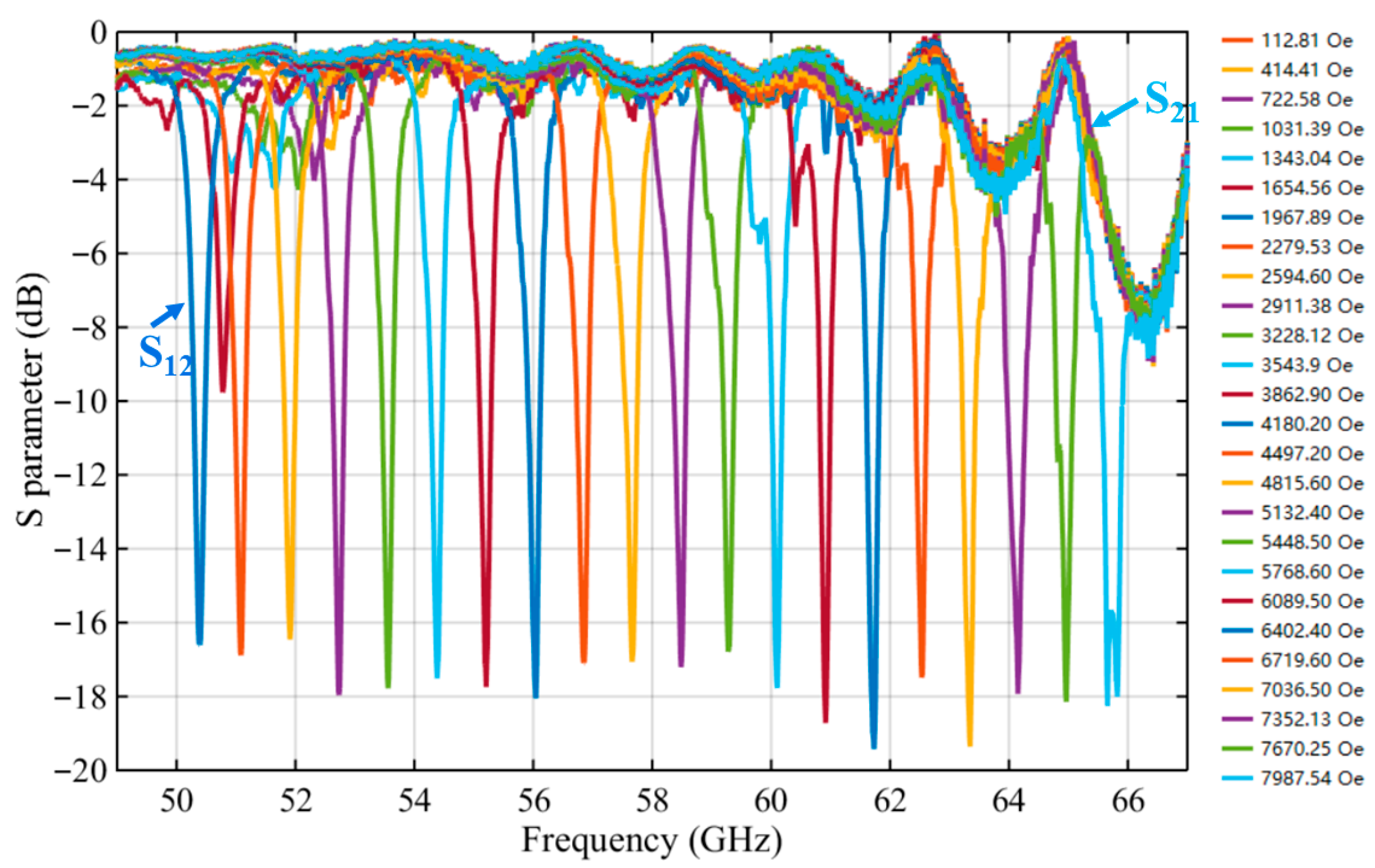
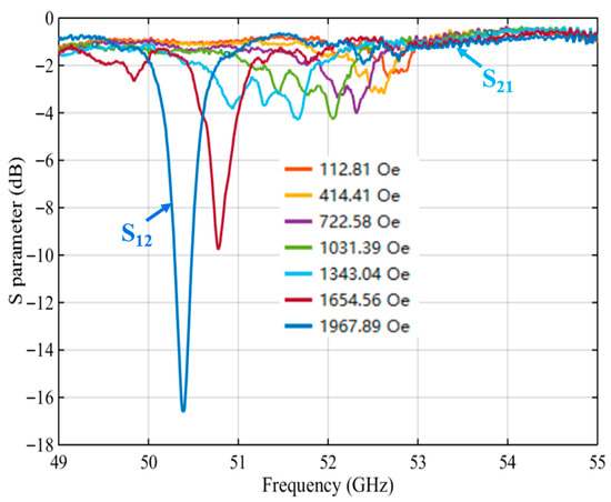
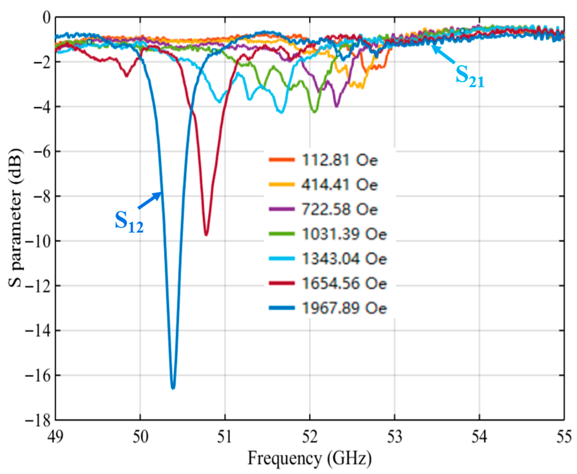
Figure 7 shows the frequency responses of S21 and S12 of the isolator under various H0, while Figure 8 presents an enlarged view of the weak-field region in Figure 7. The measurement results clearly indicate that the resonance frequency shifts progressively to higher values as the H0 intensifies. This is because the ferromagnetic resonance frequency is directly related to H0, as expressed by Equation (15) (ignoring the demagnetizing field). Under a weak H0, the magnetic moments within the ferrite are not yet fully aligned with the field direction. As a result, the off-diagonal components of the permeability tensor remain relatively weak, and the nonreciprocal effect is not sufficiently established. This leads to inadequate reverse isolation performance, manifested as limited attenuation depth in S12 and thus insufficient isolation. As the magnetic field continues to increase, the ferrite approaches magnetic saturation, leading to a more pronounced nonreciprocal response. This is reflected in the S12 curve by a significantly increased attenuation depth. At a H0 of approximately 1967.89 Oe, a distinct resonance dip appears in S12, indicating that the isolation performance has reached an optimized level.
Figure 7.
S21 and S12 versus frequency under different magnetic bias fields.
Figure 8.
Isolator S-parameters under weak bias field (close-up of Figure 7).
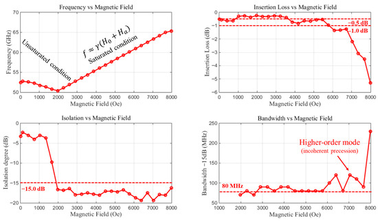
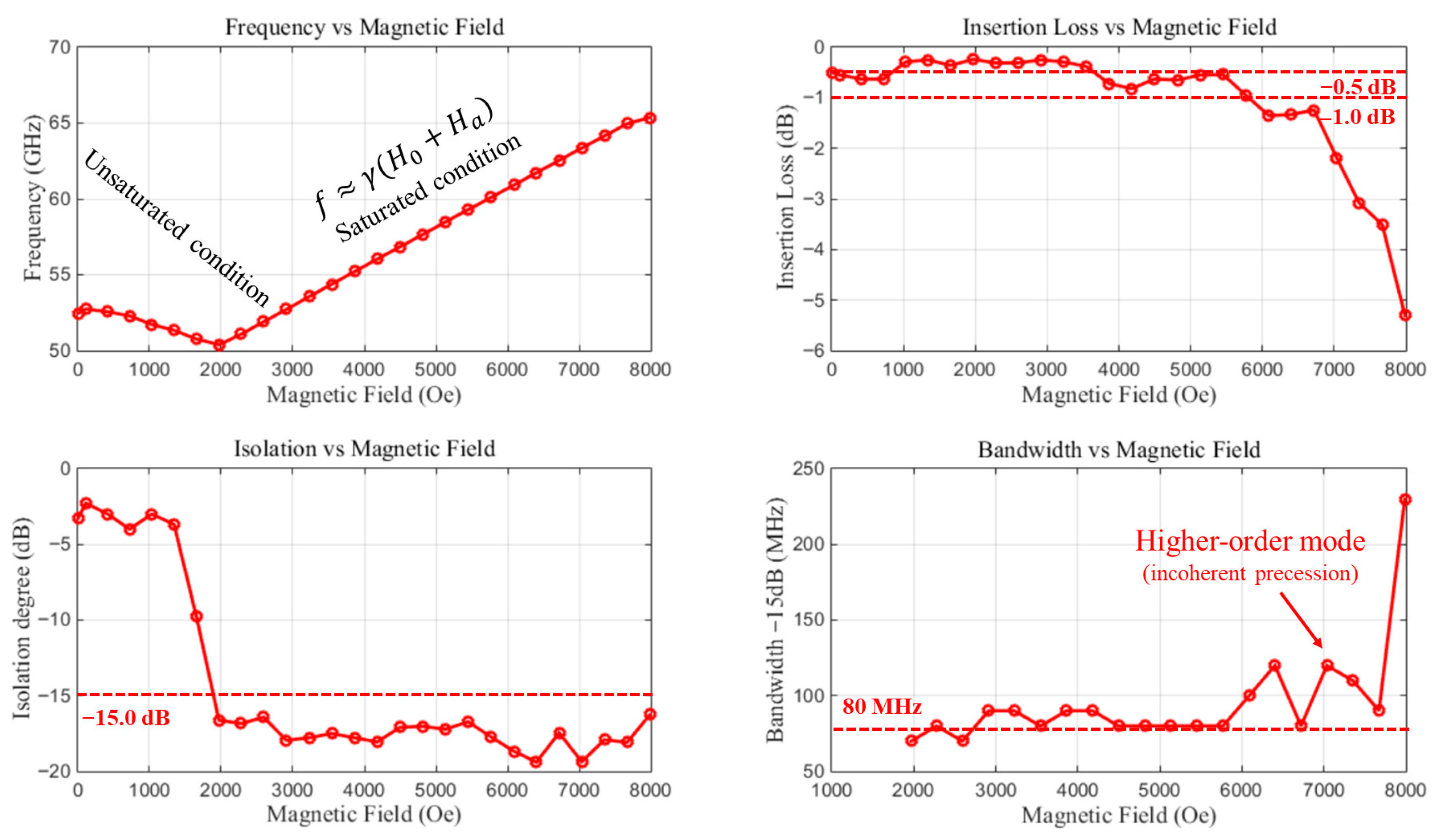
Figure 9 presents the evolution of the operating frequency, insertion loss, isolation, and bandwidth of the isolator as a function of the bias magnetic field. As the H0 increases, the operating frequency initially decreases and subsequently transitions into a monotonic rise that follows the trend predicted by Equation (14). The initial frequency reduction arises from the fact that, under low bias, the ferrite is not fully magnetized and contains multi-domain structures with non-uniform magnetization orientations. In this unsaturated regime, the magnetic resonance behaves as a non-uniform precession mode whose resonance frequency is inversely related to the external field. Once the bias field becomes sufficiently strong to align all magnetic moments and drive the ferrite into magnetic saturation, the material enters the ferromagnetic-resonance-dominated regime, where the resonance frequency increases approximately linearly with the applied field.
Figure 9.
Variation in operating frequency, insertion loss, isolation, and bandwidth with magnetic bias field.
The device exhibits exceptionally low insertion loss, remaining below −0.5 dB across the frequency range of 51.73~54.38 GHz. A minimum insertion loss of approximately −0.24 dB is achieved at H0 around 1967.89 Oe, corresponding to a frequency of 50.39 GHz. At both low and excessively high bias fields, however, the insertion loss deteriorates. In the weak-field region, the degradation is attributed to insufficient magnetization and enhanced magnetic losses associated with domain-wall and non-uniform precession processes. At high magnetic fields, the resonance-enhanced operating frequency shifts well beyond the single-mode transmission band of the WR18 waveguide (39.2–59.6 GHz). Operation in the over-cutoff or multi-mode region inevitably leads to additional propagation loss, thereby increasing the insertion loss.
The isolation characteristics exhibit a similar dependence on the magnetization state. In the weak-field region, the isolation is poor due to limited resonance selectivity and the absence of a well-defined FMR absorption peak. As the magnetic field increases, the isolation improves markedly. When the bias field exceeds approximately 1967.89 Oe, the isolation consistently surpasses −15 dB, and the maximum isolation of about −19.39 dB is obtained at 6402.40 Oe.
The operational bandwidth remains around 80 MHz for most bias fields, which is primarily limited by the intrinsically narrow ferromagnetic resonance linewidth of the ferrite material. When the bias field exceeds roughly 6000 Oe, the bandwidth increases significantly. This broadening originates from the transition from uniform FMR to non-uniform spin-wave excitations, where higher-order spin-wave modes contribute to additional absorption. While this expansion widens the usable operating band, it is accompanied by increased magnetic loss, which explains the simultaneous deterioration of insertion loss in the high-field region.
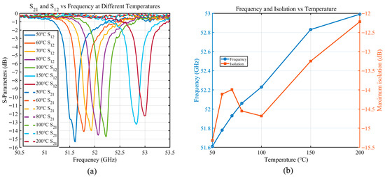
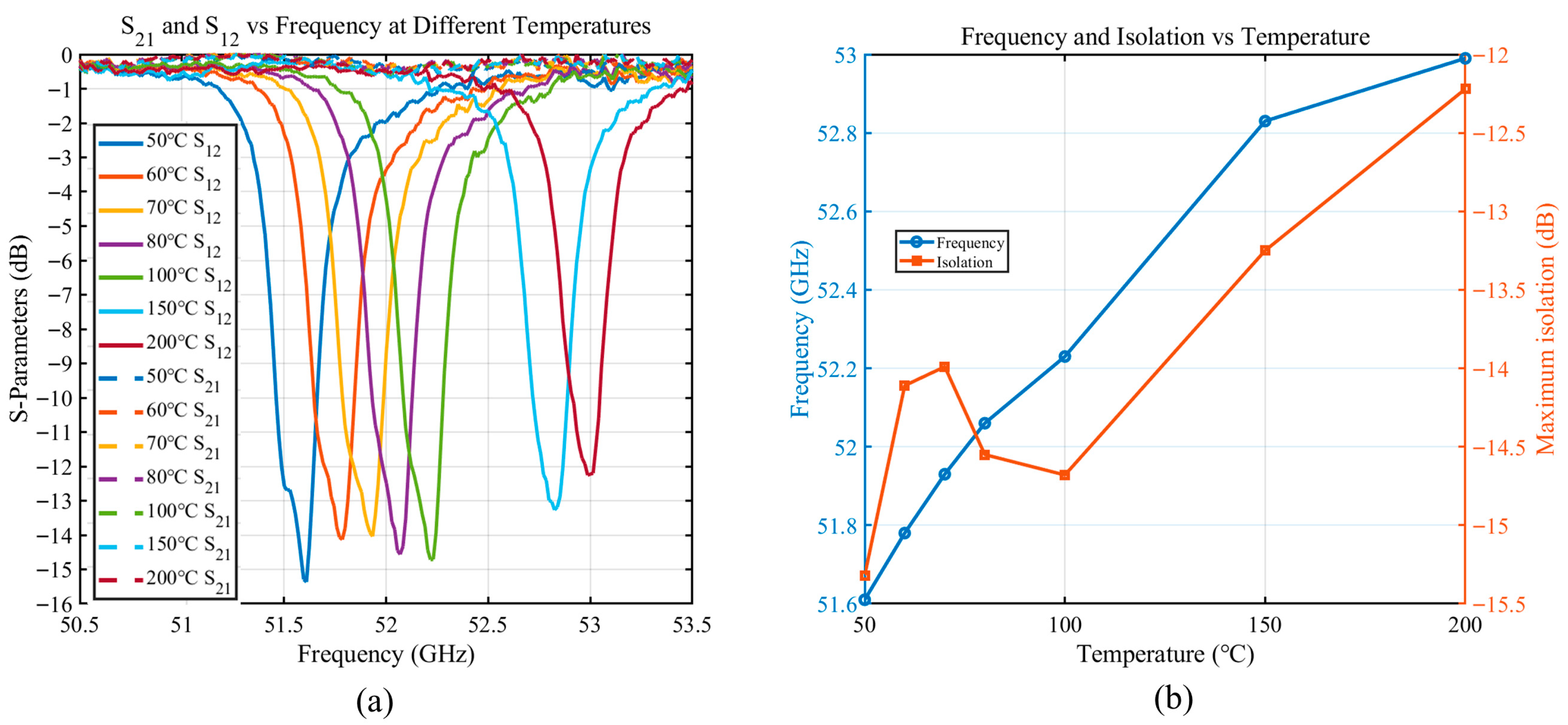
Figure 10 shows the measured S21 and S12 responses of the isolator under different operating temperatures. As the temperature increases, the operating frequency of the device exhibits a clear upward shift. This behavior can be attributed to the intrinsic temperature dependence of the ferrite’s magnetic properties. Specifically, Ms decrease with temperature, effectively modifying the FMR condition and causing the resonance frequency to move toward higher values. As a result, when the temperature increases from 50 °C to 200 °C, the operating frequency shifts from 51.6 GHz to approximately 53 GHz, corresponding to a total shift of 1.4 GHz. A linear fit reveals an approximately linear temperature coefficient of 9 MHz/°C. In addition to the frequency shift, the maximum isolation decreases gradually as temperature rises. The isolation level drops from −15.32 dB at 50 °C to −12.2 dB at 200 °C, corresponding to a degradation of about 3.12 dB. In practical applications, magnetic compensation can be employed to maintain stable device performance.
Figure 10.
Temperature-dependent S-parameters and isolation characteristics of the isolator. (a) Measured S21 and S12 responses at different temperatures. (b) Variation in operating frequency and maximum isolation with temperature.
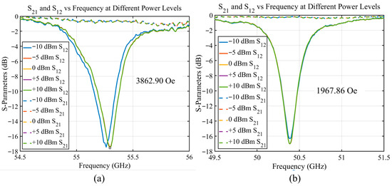
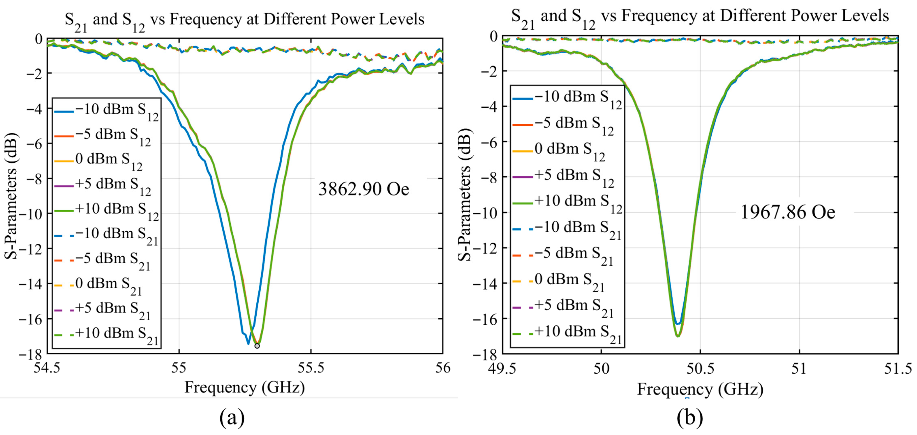
Figure 11 shows the measured S21 and S12 parameters of the device under different input power levels. Figure 11a corresponds to a bias field of 3862.90 Oe, while Figure 11b corresponds to 1967.86 Oe. Across a wide range of input powers from −10 dBm to +10 dBm, the resonance frequency, insertion loss, and isolation level exhibit almost no observable variation. This indicates that the device maintains highly stable nonreciprocal behavior over the tested power range, with no evidence of power-dependent nonlinear effects in the ferrite. A slight deviation observed in the S12 curve at −10 dBm in Figure 11a is likely attributed to measurement uncertainty or instrument noise rather than an actual degradation of device performance. Overall, the measurement results demonstrate that the isolator exhibits excellent power stability under both high-field and low-field operating conditions.
Figure 11.
S21 and S12 vs. frequency at different power levels. (a) 3862.90Oe; (b) 1967.86 Oe.
6. Conclusions
This work presents a novel magnetically tunable U-band isolator that utilizes the FMR absorption effect for nonreciprocal transmission. By integrating a BaM single-crystal array into a rectangular waveguide, the device leverages BaM’s high magnetocrystalline anisotropy to achieve efficient operation in the U-band with a relatively low external bias field. The narrow FMR linewidth of the BaM single crystal ensures exceptionally low insertion loss, with a minimum of −0.24 dB at 50.39 GHz and remaining below −0.5 dB across the 51.73–54.38 GHz frequency band, while maintaining isolation greater than −15 dB. The device demonstrates broad magnetic tunability, with the operating frequency dynamically adjustable via the external bias field. Temperature stability tests show a temperature coefficient with a frequency of approximately 9 MHz/°C, with isolation fluctuations within 3.12 dB, confirming the device’s stability under varying environmental conditions. Furthermore, power handling tests demonstrate stable operation up to 10 dBm input power. This isolator offers a promising solution for low-loss, adaptive isolators in next-generation millimeter-wave communication, radar, and sensing systems, with significant advantages in efficiency, tunability, and environmental stability.
Author Contributions
Conceptualization, F.W. and H.L.; methodology, F.W.; software, Z.L.; validation, S.Y. and W.L.; formal analysis, F.W.; investigation, H.L.; resources, H.Z.; data curation, Q.Y.; writing—original draft preparation, F.W.; writing—review and editing, Q.Y.; funding acquisition, Q.Y. All authors have read and agreed to the published version of the manuscript.
Funding
This work was supported by the National Natural Science Foundation of China (U2341286, 51472046, and 52072062); the National Key Research and Development Program of China (SQ2018YFE0205600); and the Sichuan Science and Technology Support Program (2023YFG0072).
Data Availability Statement
Data are available on request from the authors.
Conflicts of Interest
The authors declare no conflicts of interest.
References
- Wang, G.; Lu, L. Topological Microwave Isolator with >100-dB Isolation. Nat. Photon. 2025, 19, 1064–1069. [Google Scholar] [CrossRef] [Scilit]
- Demarets, M.; Vadiraj, A.M.; Caloz, C.; De Greve, K. Broadband Magnetless Isolator Using Adiabatic Flux Modulation. arXiv 2025, arXiv:2509.24551. [Google Scholar] [CrossRef] [Scilit]
- Erickson, N.R. Very Low Loss Wideband Isolators for Mm-Wavelengths. In Proceedings of the 2001 IEEE MTT-S International Microwave Sympsoium Digest (Cat. No.01CH37157), Phoenix, AZ, USA, 20–24 May 2001; IEEE: New York, NY, USA, 2001; Volume 2, pp. 1175–1178. [Google Scholar]
- Barnes, C.E. Broad-Band Isolators and Variable Attenuators for Millimeter Wavelengths. IEEE Trans. Microw. Theory Tech. 1961, 9, 519–523. [Google Scholar] [CrossRef]
- Kord, A.; Sounas, D.L.; Alu, A. Microwave Nonreciprocity. Proc. IEEE 2020, 108, 1728–1758. [Google Scholar] [CrossRef] [Scilit]
- Zhou, W.; Xiong, Y.; Chen, C.; Su, S.; Yang, Y. Design of Low-Loss Microstrip Circulator Based on NiCuZn Ferrite Material. In Proceedings of the 2025 4th International Conference on Electronics, Integrated Circuits and Communication Technology (EICCT), Chengdu, China, 11–13 July 2025; IEEE: New York, NY, USA, 2025; pp. 169–172. [Google Scholar]
- Masui, S.; Kojima, T.; Uzawa, Y.; Onishi, T. A Novel Microwave Nonreciprocal Isolator Based on Frequency Mixers. IEEE Microw. Wirel. Technol. Lett. 2023, 33, 1051–1054. [Google Scholar] [CrossRef] [Scilit]
- Noguchi, T. New Edge-Guided Mode Isolator Using Ferromagnetic Resonance Absorption. IEEE Trans. Microw. Theory Tech. 1977, 25, 100–106. [Google Scholar] [CrossRef] [Scilit]
- Hines, M.E.; Anderson, W.W. Wide-Band Resonance Isolator. IEEE Trans. Microw. Theory Tech. 1961, 9, 63–67. [Google Scholar] [CrossRef] [Scilit]
- Porterfield, D.W. Broadband Millimeter-Wave Hybrid Circulators. IEEE Trans. Microw. Theory Tech. 2023, 71, 3501–3507. [Google Scholar] [CrossRef] [Scilit]
- Porterfield, D.W. Recent Advancements in mmWave Isolator Technology. Microw. J. 2019, 62, 31908. [Google Scholar]
- Laur, V.; Gouavogui, J.P.; Balde, B. C-Band Hybrid 3-D-Printed Microwave Isolator. IEEE Trans. Microw. Theory Tech. 2021, 69, 1579–1585. [Google Scholar] [CrossRef] [Scilit]
- Fox, A.G.; Miller, S.E.; Weiss, M.T. Behavior and Applications of Ferrites in the Microwave Region. Bell Syst. Tech. J. 1955, 34, 5–103. [Google Scholar] [CrossRef] [Scilit]
- Enander, B. A New Ferrite Isolator. Proc. IRE 1956, 44, 1421–1430. [Google Scholar] [CrossRef] [Scilit]
- Taft, D.R.; Harrison, G.R.; Hodges, L.R. Millimeter Resonance Isolators Utilizing Hexagonal Ferrites. IEEE Trans. Microw. Theory Tech. 1963, 11, 346–356. [Google Scholar] [CrossRef] [Scilit]
- Dmitriev, V.; Zimmer, D.; Portela, G. Vortex-Based Ferromagnetic Resonance Isolator in 2D Photonic Crystal Waveguide. In Proceedings of the 2017 SBMO/IEEE MTT-S International Microwave and Optoelectronics Conference (IMOC), Aguas de Lindoia, Brazil, 27–30 August 2017; IEEE: New York, NY, USA, 2017; pp. 1–5. [Google Scholar]
- Capraro, S.; Rouiller, T.; Le Berre, M.; Chatelon, J.-P.; Bayard, B.; Barbier, D.; Rousseau, J.J. Feasibility of an Integrated Self Biased Coplanar Isolator with Barium Ferrite Films. IEEE Trans. Compon. Packag. Technol. 2007, 30, 411–415. [Google Scholar] [CrossRef] [Scilit]
- Li, Q. 60GHz Resonance Isolator. Ph.D. Dissertation, University of Minnesota, Minneapolis, MN, USA, December 2015. [Google Scholar]
- Dillon, B.M.; Gibson, A.A.P. Nonuniform Magnetization in Microwave Ferrite Components by Finite Element Analysis. Electromagnetics 2002, 22, 345–355. [Google Scholar] [CrossRef] [Scilit]
- Seewald, C.K.; Bray, J.R. Ferrite-Filled Antisymmetrically Biased Rectangular Waveguide Isolator Using Magnetostatic Surface Wave Modes. IEEE Trans. Microw. Theory Tech. 2010, 58, 1493–1501. [Google Scholar] [CrossRef] [Scilit]
- Polder, D., VIII. On the Theory of Ferromagnetic Resonance. Lond. Edinb. Dublin Philos. Mag. J. Sci. 1949, 40, 99–115. [Google Scholar] [CrossRef] [Scilit]
- Adam, J.D.; Davis, L.E.; Dionne, G.F.; Schloemann, E.F.; Stitzer, S.N. Ferrite Devices and Materials. IEEE Trans. Microw. Theory Tech. 2002, 50, 721–737. [Google Scholar] [CrossRef] [Scilit]
- Vartanian, P.H.; Ayres, W.P.; Melchor, J.L. Broadband Ferrite Microwave Isolator. IEEE Trans. Microw. Theory Tech. 1956, 4, 8–13. [Google Scholar] [CrossRef] [Scilit]
- Noferesti, M.; Djerafi, T. A Tunable Ferrite Isolator for 30 GHz Millimeter-Wave Applications. IEEE Trans. Magn. 2021, 57, 4001707. [Google Scholar] [CrossRef] [Scilit]
- Wittenauer, M.A.; Nyenhuis, J.A.; Schindler, A.I.; Sato, H.; Friedlaender, F.J.; Truedson, J.; Karim, R.; Patton, C.E. Growth and Characterization of High Purity Single Crystals of Barium Ferrite. J. Cryst. Growth 1993, 130, 533–542. [Google Scholar] [CrossRef] [Scilit]
- Wang, F.; Zhang, Y.; Li, H.; Yang, S.; Zhang, H.; Yang, Q. Study on the Faraday Rotation Angle of La-Substituted Barium Hexaferrite in the Terahertz Band. Opt. Express 2024, 32, 25165. [Google Scholar] [CrossRef] [Scilit] [PubMed]
- Wang, X.; Wang, B.; Wei, S.; Wang, Y.; Liang, Y. Effect of Sintering Temperature on the Microstructure, Magnetic, and Microwave Absorption Properties of M-Type Barium Ferrite Nanoparticles Prepared by Sol–Gel Method. J. Mater. Sci. Mater. Electron. 2023, 34, 1045. [Google Scholar] [CrossRef] [Scilit]
- Wagner, D.V.; Kareva, K.V.; Zhuravlev, V.A.; Bugrova, T.A.; Tsimmerman, A.I.; Minin, R.V. Study of the Phase Composition, Structural and Magnetic Properties of M−type Hexaferrites Produced by Self-Propagation High-Temperature Synthesis. J. Magn. Magn. Mater. 2025, 618, 172887. [Google Scholar] [CrossRef] [Scilit]

Disclaimer/Publisher’s Note: The statements, opinions and data contained in all publications are solely those of the individual author(s) and contributor(s) and not of MDPI and/or the editor(s). MDPI and/or the editor(s) disclaim responsibility for any injury to people or property resulting from any ideas, methods, instructions or products referred to in the content. |
© 2026 by the authors. Licensee MDPI, Basel, Switzerland. This article is an open access article distributed under the terms and conditions of the Creative Commons Attribution (CC BY) license.