


Abstract
Since the thermal reliability issues of terahertz traveling wave tubes (THz TWTs) severely limit their power capacity, we propose a thermal analysis and optimization process for THz TWTs in this paper. The measurement results from the accessible test points exhibited good consistency with those of the thermal analysis. Based on the analysis of the heat generation mechanisms of each component of the THz TWT, two novel thermal conduction structures were introduced that decreased the operating temperature of the output window from 81 °C to 34 °C and decreased the operating temperature of the slow wave structure (SWS) from 103 °C to 56 °C. According to the simulation results for the maximum allowable internal power dissipation under the optimized structure, these novel optimization strategies theoretically double the power capacity of the SWS. This work demonstrates an experimentally validated full-tube thermal model and establishes a transferable optimization principle based on identifying and eliminating thermal bottlenecks through a strategic heat conduction path design. This study provides an effective approach for improving the thermal reliability and power capacity of THz TWTs, providing technical support for the engineering application of high-power THz TWTs.
1. Introduction
As the operational frequencies of traveling wave tubes (TWTs) are continuously extended to higher frequency bands, terahertz traveling wave tubes (THz TWTs) have broad application prospects in various fields, including wireless communications, imaging, plasma diagnostics, healthcare, security inspection, and scientific research [1].
To support the development of high-frequency vacuum electronic devices, the U.S. Defense Advanced Research Projects Agency (DARPA) launched several research programs aimed at developing THz vacuum electronic amplifiers. A prominent example was the “High Frequency Integrated Vacuum Electronics (HiFIVE)” program, which aimed to develop highly integrated, high-power amplifiers for broadband, high-power transmitters by leveraging microfabrication techniques. The primary research directions of this program included enhancing the bandwidth, power, and efficiency of these devices; optimizing thermal management under high thermal loads; and reducing the device size for compact high-power amplifiers.
Under the HiFIVE program, Northrop Grumman (NGC) developed a 220 GHz folded-waveguide TWT amplifier. In subsequent tests at 214 GHz, the amplifier achieved a maximum output power of 55.5 W over a 5 GHz bandwidth [2]. Additionally, DARPA launched the “Terahertz Electronics (THzE)” program, which focused on the development of key devices and integration technologies for compact, high-performance electronic circuits operating above 1 THz. The program was divided into three phases to explore viable compact THz devices in the sub-millimeter wavelength range, with Phase 1 targeting 670 GHz, Phase 2 targeting 850 GHz, and Phase 3 targeting 1.03 THz.
Supported by the THzE program, NGC also developed a 670 GHz folded-waveguide TWT amplifier, which achieved an output power of 108 mW [3]. Subsequently, NGC designed an 850 GHz folded-waveguide TWT amplifier and fabricated its slow-wave circuit. The test results for this fabricated amplifier indicated that it achieved an output power of 39.4 mW at 850 GHz [4]. Ultimately, NGC completed the development of a 1.03 THz folded-waveguide TWT with an output power of 29 mW [5].
DARPA’s third relevant initiative was the Video Synthetic Aperture Radar (ViSAR) program, which aimed to develop a video synthetic aperture radar system capable of tracking maneuvering targets in adverse weather conditions, such as clouds, dust, and dense fog. A core task of this program was the development of a compact, airborne-compatible, and medium-power amplifier in the extremely high-frequency band. Under this program, Northrop Grumman developed a THz TWT capable of delivering a maximum output power of 79 W in the 232.6–234.6 GHz range [6]. Building on this TWT, Raytheon further developed a 235 GHz airborne radar system [7].
Additionally, the European Union launched the OPTHER program, which focused on THz vacuum electronic amplifiers [8]. The aim of this program was to overcome the power limitations of THz-band amplifiers by developing a novel, compact, efficient, and reliable vacuum THz amplifier to enhance the performance of THz radiation sources. An Italian research team, supported by OPTHER, proposed a THz TWT design that incorporated a double corrugation rectangular waveguide to form the slow-wave structure (SWS) [9].
In China, multiple research teams, including the Aerospace Information Research Institute (AIR), the Beijing Vacuum Electronics Research Institute (BVERI), and the China Academy of Engineering Physics (CAEP), have conducted extensive research on THz TWTs. Their achievements included the development of a 0.22 THz TWT with an average output power of 12 W [10], a broadband 0.33–0.355 THz TWT with an output power of 1 W [11], and a 0.336 THz TWT with an output power exceeding 3.1 W [12].
These reports indicate that, with the support of various institutions, many research teams have endeavored to improve the performance of THz TWTs, but their output power is severely limited compared with that of low-frequency TWTs. A primary reason for this is the “size-scaling effect”. Higher operating frequencies require proportionally smaller dimensions for the SWS and the electron beam channel. Specifically, the internal dimensions of the SWS must be scaled down to sub-millimeter or even micron levels to maintain effective synchronous interaction between the electron beam and the electromagnetic waves. This miniaturization of the SWS, combined with the demand for high device integration, limits the device’s thermal load capacity. Furthermore, the miniaturization of the electron beam channel increases the likelihood of electron interception by the channel walls due to space charge repulsion and diffusion, thereby accelerating heat accumulation. Consequently, the output power of a THz TWT is fundamentally limited by its thermal capacity and heat dissipation capability. Therefore, any effort to increase the average output power will likely lead to the melting or burnout of thermally vulnerable components (e.g., the SWS) due to heat accumulation. This limitation impedes the broader application of THz TWTs.
To address the thermal reliability issues of these THz TWTs, we note that the conventional design methods for low-frequency vacuum electronic devices are no longer applicable [13,14]. Published studies on THz TWTs mainly focus on the electrical design of the entire tube [15,16], with some reports only involving the thermal analysis of the electron gun [17] or collector [18,19]. However, there are no relevant reports on the thermal reliability enhancement design for thermally vulnerable structures (e.g., high-frequency systems) in THz TWTs. As a result, it is imperative to optimize the thermal design of the main heat-generating structures and mitigate the thermal vulnerability of critical weak points in THz TWTs, thereby improving their heat dissipation capability and unlocking greater potential for power capacity enhancement.
Based on the targeted redesign of the internal thermal conduction path, this work makes the following novel contributions:
- The design of a full-tube thermal model of a 0.22 THz TWT validated against experimental measurements at multiple locations;
- The identification of thermal bottlenecks through heat flux mapping;
- The development of two innovative internal heat conduction structures that leverage existing component geometries;
- The description of a transferable methodology for thermal optimization applicable to other THz TWT architectures.
With the thermal challenges and limitations of existing research clarified, Section 2 presents a systematic analysis of the heat generation mechanisms in each TWT component.
2. Heat Generation Analysis of the THz TWT
The primary structures of a TWT comprise several key modules, including an electron gun, a slow-wave structure (SWS), a focusing system, an output waveguide, an input waveguide, a collector, a base plate, and support components.
2.1. Electron Gun
The primary function of the electron gun (which typically employs an indirectly heated cathode for electron emission) is to generate an electron beam with a specific shape and current density. The design of the indirectly heated cathode helps maintain the potential and uniform temperature of the cathode, achieve a high emission current density, and guarantee the stability and quality of the electron beam. When energized, the filament generates heat that is conducted to the ceramic material inside the cathode-supporting cylinder. This heat is then transferred to the cathode, causing it to heat up. Once the cathode surface reaches the target temperature, the energy of the electrons exceeds the cathode material’s work function, causing electrons to be emitted from the surface. The anode then accelerates these emitted electrons to a specific velocity via an electric field, enabling them to exchange energy with the electromagnetic field within the SWS.
Compared to lower-frequency TWTs, the electron guns used in THz TWTs are further miniaturized to the sub-millimeter scale. Consequently, to ensure key performance metrics such as electron efficiency, lifespan, gain, and linearity, all components of the electron gun must be redesigned. When the core components meet electrical performance requirements, they can reach temperatures exceeding 1000 °C. If the electron gun is not properly designed, excess heat can be transferred through its structure and can potentially damage other TWT components.
2.2. Slow-Wave Structure (SWS)
The SWS is the core component of a TWT. Its function is to receive the input electromagnetic waves from the input structure and the electron beam from the electron gun. Through its structural and dimensional design, the SWS creates an environment for continuous energy exchange between the electron beam and the electromagnetic waves. To achieve this, the axial phase velocity of the electromagnetic waves must be reduced to match the velocity of the electron beam. This synchronization allows electrons to be decelerated by the electromagnetic field components, thereby enabling them to transfer their energy to the electromagnetic waves, which are then amplified. The amplified waves are then coupled out through the output structure. Thus, the SWS critically determines the TWT’s operating frequency, bandwidth, output power, and gain.
Furthermore, to confine the electron beam and ensure that it passes unimpeded through the entire SWS without being intercepted by the channel walls during energy exchange, a magnetic focusing system is typically constructed around the SWS. This system uses a magnetic force to counteract the space charge repulsion of the electron beam, preventing high-energy electrons from bombarding the beam channel.
The heat generation within the SWS stems from two sources: thermal energy generated by electron beam bombardment, and ohmic losses from the propagation of electromagnetic waves. This heat accumulation is particularly problematic in the small-scale structure of a THz TWT SWS, potentially leading to the burnout of the SWS. This is a key factor limiting the output power of THz TWTs. Therefore, improving the heat dissipation of the SWS is crucial for enhancing its thermal capacity and thus increasing the sustainable output power of the THz TWT. For this reason, it is crucial to focus on the thermal distribution and heat conduction in this area and to perform targeted thermal optimization.
2.3. Collector
The collector’s function is to receive the spent electrons from the end of the SWS. As these electrons still have high kinetic energy, their impact on the collector converts their kinetic energy into thermal energy. This energy must be dissipated rapidly to prevent overheating and damage.
2.4. Base Plate and Support Structures
After the design of the main components responsible for the TWT’s electrical performance is completed, support structures for these components typically need to be designed. Support structures serve to facilitate the tube’s mounting and to conduct and dissipate heat.
2.5. Simplification of the Model
The 3D CAD model of the THz TWT was created based on the structural design drawings. However, the original 3D CAD model that was directly derived from the design drawings often contained features that are unsuitable for computer-aided engineering (CAE) analysis. Thus, some processing and simplification of the model are required. The simplification principles are as follows:
- The simplified model must retain key physical properties of the original model, such as mass and stiffness.
- The simplified model should facilitate meshing.
- Important areas should be subjected to minimal or no simplification.
- Structural components should be simplified in the order solids → solid shells → shells → beams → rods → springs → mass points.
Based on these principles, the following simplification methods were applied:
- Small chamfers and fillets were removed.
- Non-essential components (e.g., wires, adhesives) were removed.
- The model was divided into regular structures by component type to facilitate meshing.
- Unnecessary engravings and markings were removed.
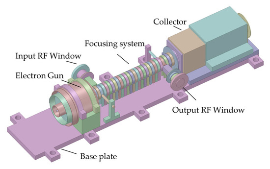
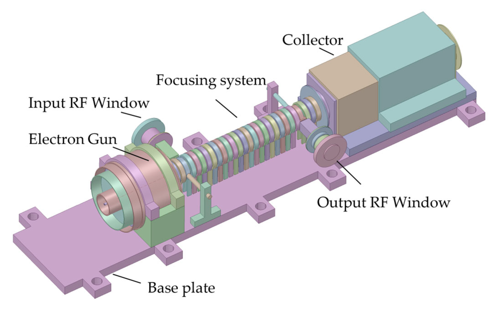
A simplified model of a THz TWT is shown in Figure 1.
Figure 1.
A simplified model of a THz TWT suitable for CAE simulation analysis.
Understanding the heat generation mechanisms in each component provides the foundation for establishing appropriate thermal loads in the finite element model. Section 3 describes how these heat loads are implemented in the simulation, along with mesh optimization to ensure numerical accuracy.
3. Preprocessing
Following the construction of the THz TWT model, preprocessing for the simulation was performed using CAE software (Ansys Workbench 2020). Preprocessing includes operations such as material assignment and meshing.
3.1. Material Parameter Setting
Material parameters critically influence the results of finite element analysis (FEA). A THz TWT typically employs more than ten types of materials. The core components of the electron gun (cathode, filament, anode, focusing electrode) were made of materials such as tungsten, tungsten–rhenium, and molybdenum. Insulating materials with low thermal conductivity were also widely used in the electron gun to prevent heat conduction from the hot cathode to other TWT components and to avoid arcing. The magnetic focusing system consisted of Sm-Co permanent magnets (which were supported and positioned by nickel–copper alloy support spacers) combined with pure iron to generate the focusing field. The RF window was made of diamond. The SWS was typically fabricated from oxygen-free high-conductivity (OFHC) copper, which ensured excellent electrical and thermal conductivities. The collector was also fabricated from oxygen-free copper to guarantee superior electrical and thermal conductivities, while its support was made of alumina with excellent dielectric and thermal barrier properties. The base plate and other support components were primarily fabricated from duralumin or iron–nickel–cobalt magnetic sealing alloys. Specific material parameters were obtained from material handbooks, while key component parameters were derived from experimental results. To facilitate the temperature field analysis under operating conditions, temperature-dependent properties were assigned to the materials, allowing the software to select the corresponding properties based on the calculated temperatures during simulation.
3.2. Manual Control of Mesh Quality and Density
To perform an FEA, the model must be meshed. After meshing, element metrics can be used to evaluate the mesh quality, with skewness being one of the primary element metrics. Skewness (Skewness = (Optimal Cell Size − Cell Size)/Optimal Cell Size) indicates how close a face or a cell is to the ideal shape (i.e., equilateral or equiangular). The smaller the skewness, the higher the quality of the mesh elements. Its classification is shown in Table 1.
Table 1.
Classification of skewness.
After automatic meshing was performed on the aforementioned model, the average skewness was 0.50979 with a standard deviation of 0.28531.
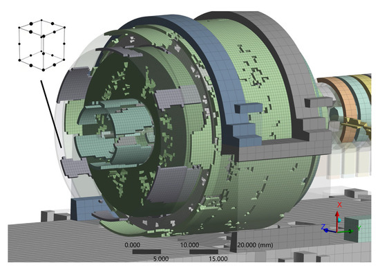
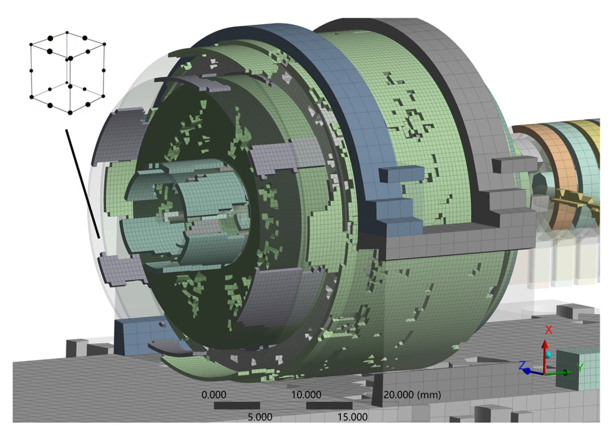
To improve the mesh quality, we used a meshing method primarily based on 20-node high-order hexahedral elements and reduced the mesh size for components with poor skewness. After optimization, the average skewness decreased from 0.50979 to 0.26968, and the standard deviation was only 0.1818. Detailed skewness analysis and figures are provided in the Supplementary Materials. The hexahedral meshes with skewness values below 0.25 after mesh optimization are shown in Figure 2.
Figure 2.
The positions of the hexahedral meshes with a skewness below 0.25 after mesh optimization, which demonstrates that the 20-node hexahedral high-order elements predominate.
With an optimized mesh and properly assigned material properties, the thermal model is now ready for application of heat loads and boundary conditions. Section 4 describes the determination of these loads, presents the baseline thermal simulation results, and validates the model against experimental measurements before proceeding to optimization.
4. Thermal Simulation and Optimization for THz TWT
After preprocessing tasks such as material assignment and meshing were completed, the device loads could be set.
4.1. Determination of Thermal Loads and Boundary Conditions
The thermal load during TWT operation stems from power dissipation, which is primarily distributed in three locations: the electron gun, the SWS, and the collector.
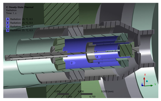
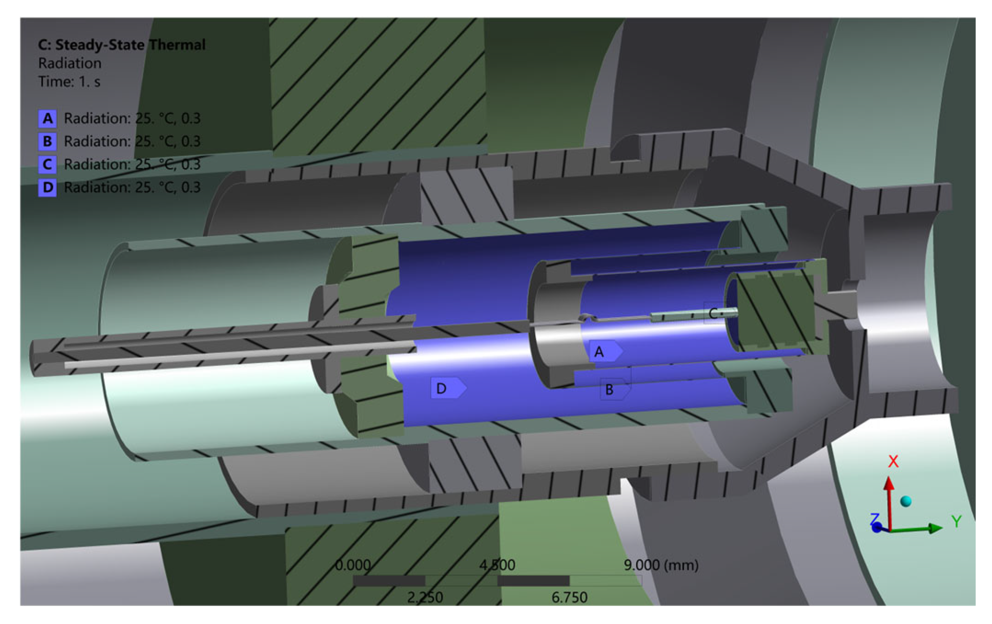
The filament of the electron gun operated at 0.68 A and 6.96 V, resulting in a thermal load of 4.73 W. The filament was encapsulated in alumina powder to ensure a uniform heat distribution. Since the volume of the alumina powder was 9.2084 mm3, the internal heat generation rate was set to 0.514 W/mm3 (4.73 W/9.2084 mm3). Additionally, due to the high temperature of the heat source and the vacuum environment, thermal radiation cannot be ignored. Therefore, four thermal radiation pairs were established at high-temperature locations, as shown in Figure 3.
Figure 3.
Loads of internal thermal radiation in the electron gun.
The power dissipation of the SWS comes from two sources: electron interception loss by the SWS, and ohmic loss due to wave propagation in the waveguide. When the TWT is powered, ohmic losses in the SWS and energy deposition from electron beam bombardment in the beam channel cause heating. Since the cathode voltage of the THz TWT was 22 kV and the measured intercepted current of the SWS during device operation was 8 mA, the power loss of the SWS was calculated as 176 W (22 kV × 8 mA). The volume of the SWS was 657.32 mm3. Therefore, the internal heat generation was set to 0.268 W/mm3 (176 W/657.32 mm3) for the SWS.
The power loss of the output window was 1 W, which accounted for 10% of the measured 10 W output power. The volume of the output window was 1.4267 mm3. Therefore, the internal heat generation was set to 0.701 W/mm3 (1 W/1.4267 mm3) for the output window.
Heat in the collector originates from the impact of the spent electron beam on its inner surface. Therefore, it is more reasonable to convert the dissipated power into heat flux density than into internal heat generation. The collector voltage of the THz TWT was 15 kV, the measured current of the collector during device operation was 19.25 mA, and the calculated dissipated power at the collector was 288.7 W (15 kV × 19.25 mA). Since the inner surface area of the collector is 886.54 mm2, an average heat flux density of 0.326 W/mm2 (288.7 W/886.54 mm2) was applied to its inner surface. The thermal loads and boundary conditions (excluding radiation) are shown in Table 2.
Table 2.
Thermal loads and boundary conditions, excluding radiation.
After the thermal loads are set, the remaining boundary conditions need to be defined. During operation, the base plate is liquid-cooled. Since the temperature across the base plate was measured to remain stable at a constant 25 °C during the verification test, to align the simulation with the test environment, a constant temperature of 25 °C was applied to the base plate as a thermal boundary condition. Furthermore, as the TWT’s outer surface is subject to natural convection, a convection coefficient of 10 W/(m2·K) was applied to all exposed faces, with an ambient temperature of 25 °C.
A sensitivity analysis of the convection coefficient (50–150% of the nominal 10 W/(m2·K)) was performed due to its strong influence on the simulation results. As shown in Table 3, the relative variation of the simulated temperatures of critical THz TWT components is within 0.6%, so the impact of this convection coefficient variation is negligible.
Table 3.
Sensitivity analysis of the convection coefficient.
4.2. Thermal Simulation Results and Verification
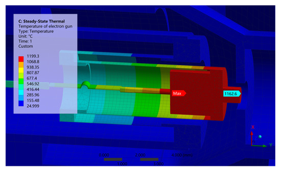
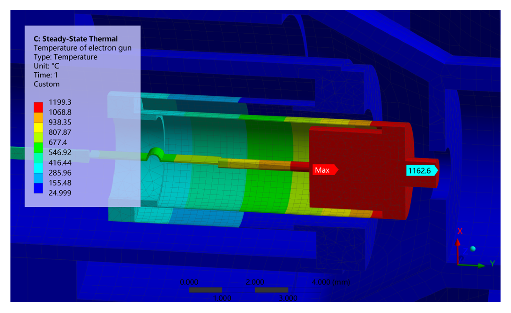
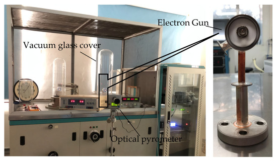
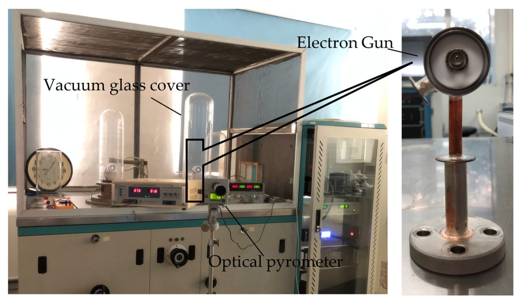
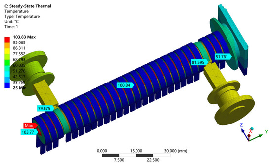
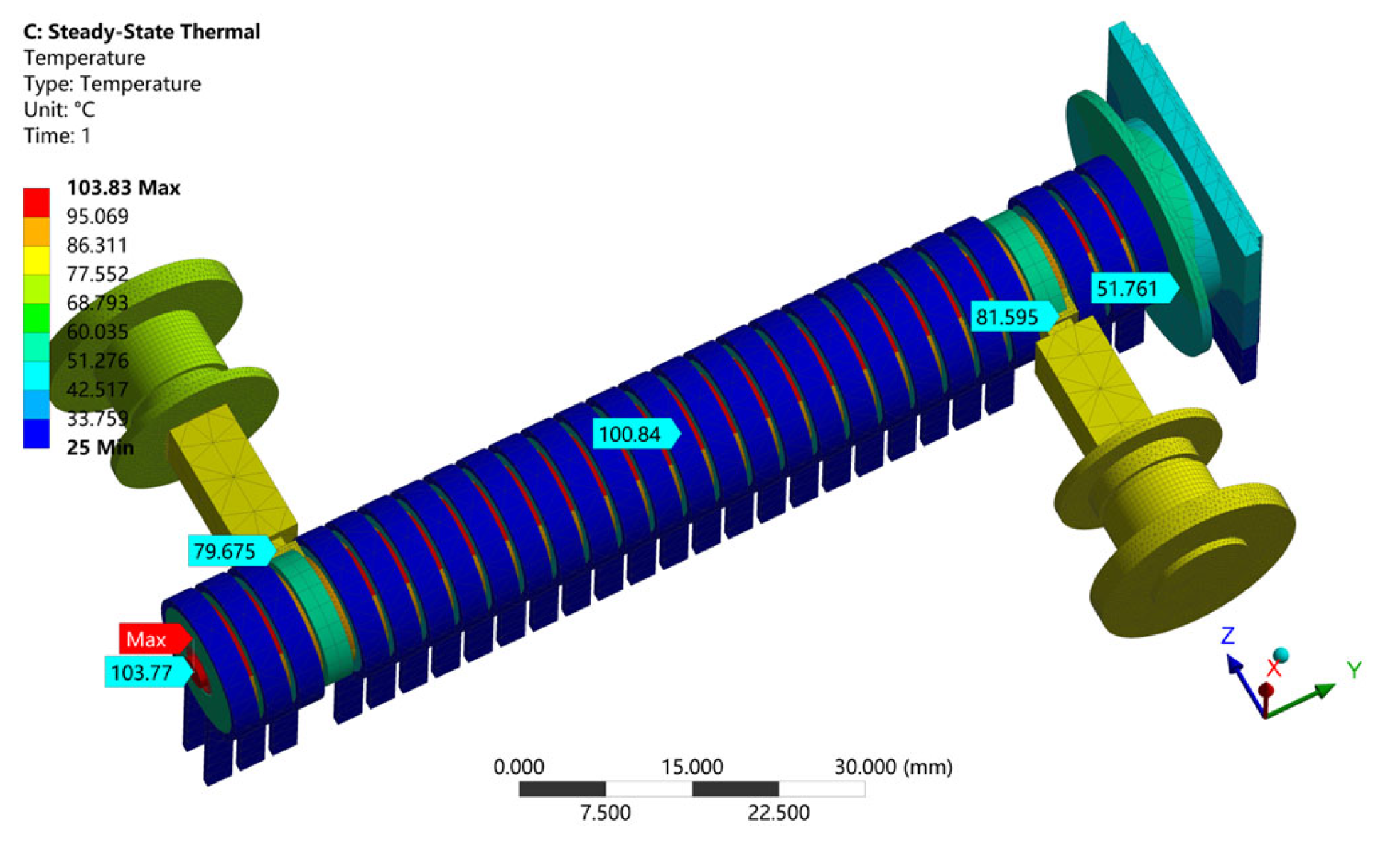
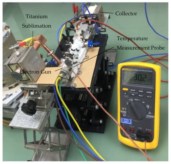
With the thermal loads and boundary conditions applied to the finite element model of the entire TWT, a steady-state thermal analysis was performed to obtain the temperature field distribution at thermal equilibrium during operation. The simulated cathode temperature was 1162.9 °C (Figure 4), closely matching the measured value of 1163 °C. A photograph of the experimental site is shown in Figure 5. The outer surface temperature of the collector is 51.761 °C (Figure 6), which is also close to the measured value of 51 °C.
Figure 4.
The simulated temperature of the electron gun assembly, which closely matched the measured value.
Figure 5.
Photograph of the experimental site.
Figure 6.
Temperature distribution of the high-frequency system, the RF window, and the collector.
Several limitations must be acknowledged:
- Inaccessible internal components: The SWS, which is the most thermally critical component, operates inside the vacuum envelope surrounded by the magnetic focusing system, making direct temperature measurement impossible. The SWS temperatures of 103 °C (pre-optimization) and 56 °C (post-optimization) are therefore model-based inferences.
- Sensor accuracy: Temperature measurements were performed using a multimeter connected to an 80 BK temperature probe with an accuracy of ±2.2 °C or 2% (whichever is greater) for collector and body surface measurements and an optical pyrometer with an accuracy of 0.6% of reading between 800 °C and 2000 °C for cathode temperature measurement.
- Repeatability: Three independent thermal cycles were performed, with temperature measurements repeated at 30 min intervals after the device reached thermal steady state. The standard deviation across measurements was <2 °C for all monitored points, indicating good repeatability.
- Measurement uncertainty: The combined uncertainty in temperature difference (ΔT) between simulated and measured values is estimated at ±9 °C for cathode measurements and ±4.2 °C for other components. All simulated values fall within these uncertainty bounds.
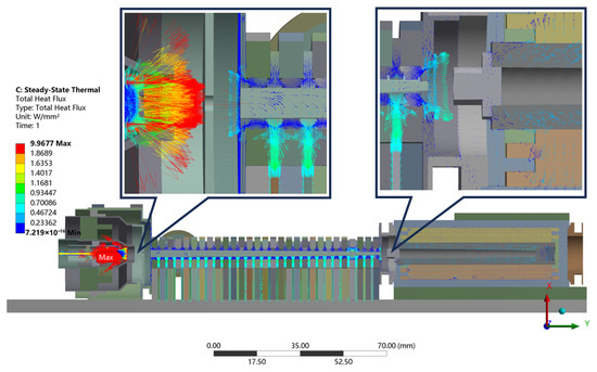
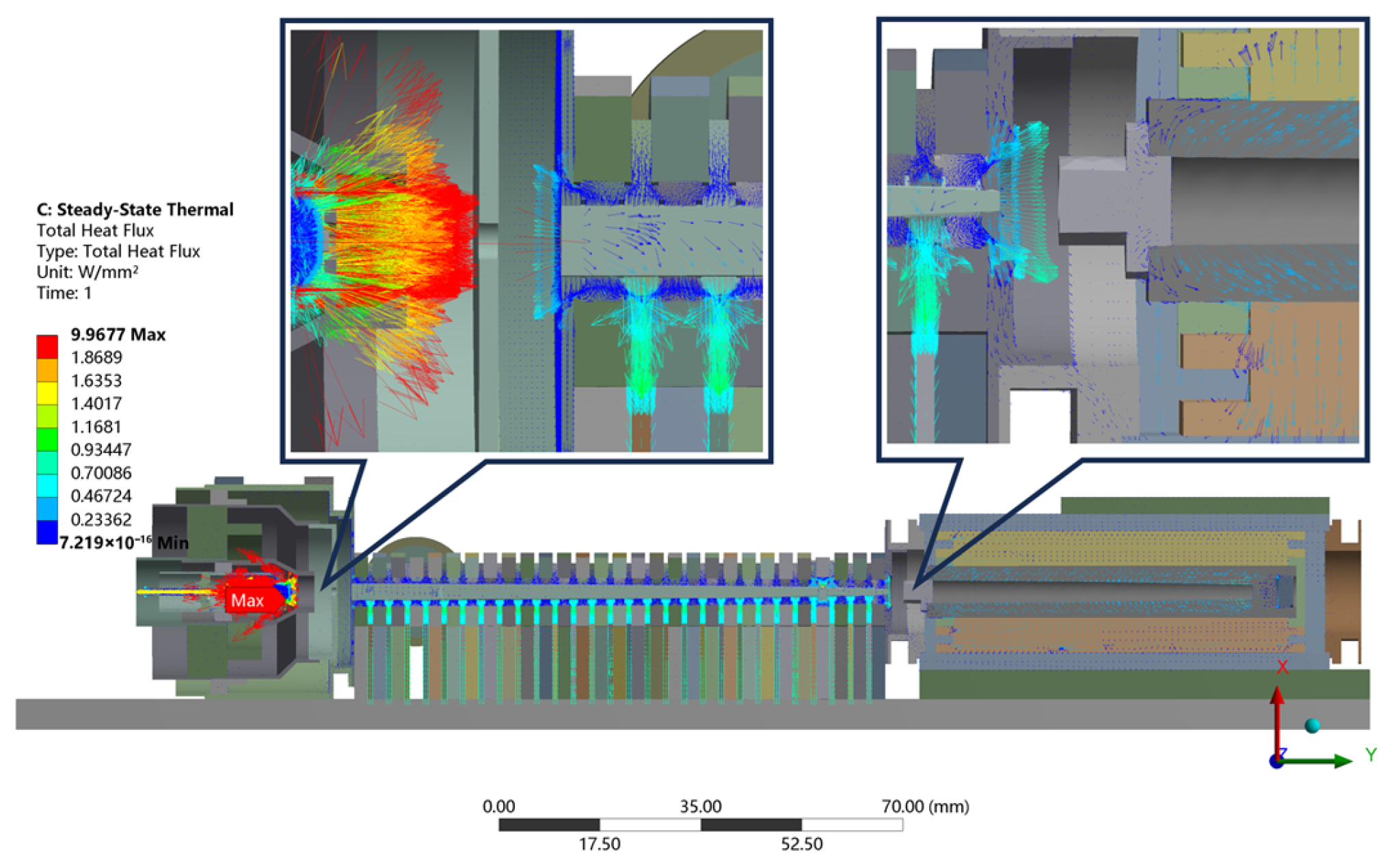
After the steady-state temperature of the entire tube was obtained, the internal heat flux distribution in each component at thermal equilibrium was extracted. The heat dissipation in each component is shown in Figure 7. Figure 7 shows the internal heat conduction direction and heat dissipation pathways of the device under operating conditions, the results of which guide the thermal optimization design.
Figure 7.
Heat flux map of the entire tube, which guides the thermal optimization design. The arrow on the left indicates that little heat is transferred from the electron gun to the high-frequency system. The arrow on the right indicates that little heat is transferred from the collector to the high-frequency system.
As shown in Figure 7, the region with the highest heat flux is the cathode assembly in the electron gun, as it is the area with the highest power density. However, an analysis of the electron gun’s material properties indicates that its components have high thermal reliability, and little heat is transferred from the electron gun or the collector to the high-frequency system. This map shows that the heat from the electron gun or the collector is effectively isolated by their respective thermal insulation design.
4.3. Optimizations and Verification
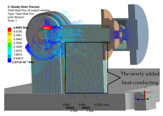
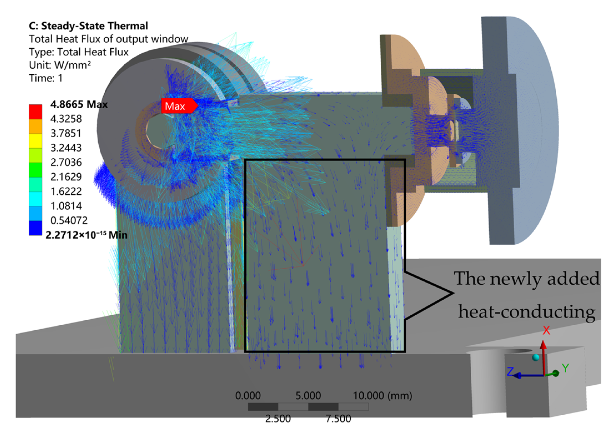
The sealing integrity of the output structure is critical for the TWT. Thermal deformation of the output structure could lead to vacuum leakage. Therefore, it is necessary to rapidly conduct the accumulated heat from the output window to the base plate. Considering that the waveguide structure within the output assembly was fabricated from OFHC copper, we designed an additional thermal conduction structure between the output window and the base plate to create a direct heat dissipation shortcut, as shown in Figure 8. The temperature of the optimized output window when the added conduction structure was made of OFHC copper (thermal conductivity: 330 W/(m·K)) decreased from 81 °C to 34 °C.
Figure 8.
Heat flux near the output window with the thermal conduction structure, which guides the thermal optimization design. The part inside the rectangular box in the figure is the newly added heat conduction structure.
The thermal design for the SWS is more complex, as its exterior typically houses the magnetic focusing system, whose functional design takes precedence. Around the cylindrical SWS, a periodic permanent magnet (PPM) focusing system is typically formed by alternately stacking Sm-Co permanent magnets and pole pieces. Pole pieces made of pure iron can guide magnetic flux lines to maximize the magnetic flux density along the electron beam direction. During PPM design, support spacers are used to position the permanent magnets. To assemble the hollow cylindrical permanent magnets onto the integrally formed SWS, each magnet is split into two halves for manufacturing and installation.
It is evident from Figure 8 that a substantial amount of heat, upon reaching the support spacers and pole pieces, encounters a thermal barrier that prevents further conduction to peripheral components, leading to localized heat accumulation.
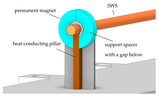
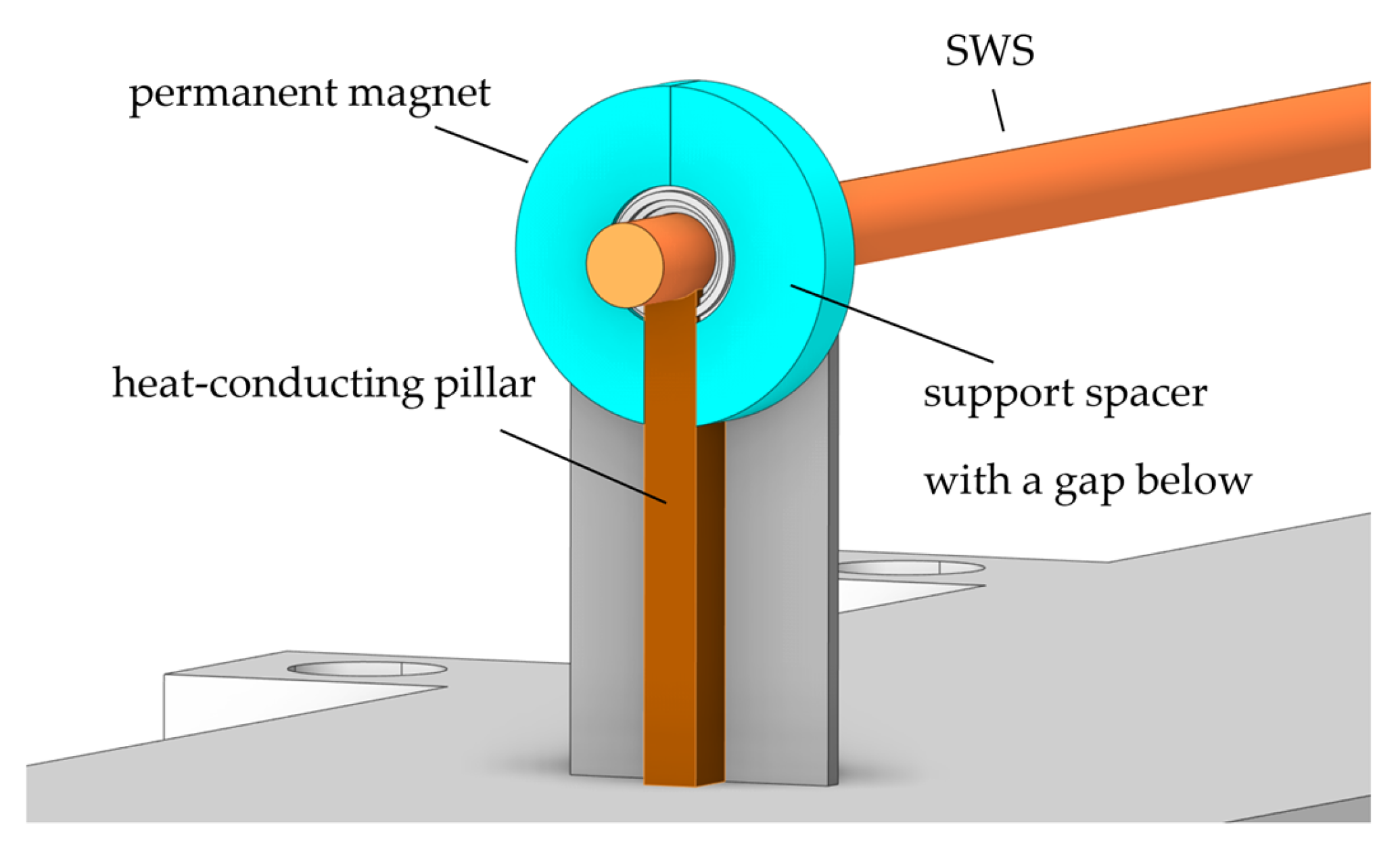
Therefore, in each period of the magnetic focusing system, a slot is designed in the support spacer, and a gap is also left between the two hollow semi-cylindrical permanent magnets. We designed a thermal conduction pillar connecting the SWS to the base plate through these slots and gaps to directly transfer the accumulated heat to the base plate.
Figure 9 shows the optimized design of the heat-conducting pillars added to one period of the magnetic focusing system.
Figure 9.
The optimized design of the heat-conducting pillars, which form multiple heat conduction paths directly to the base plate.
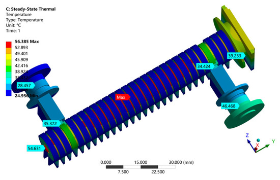
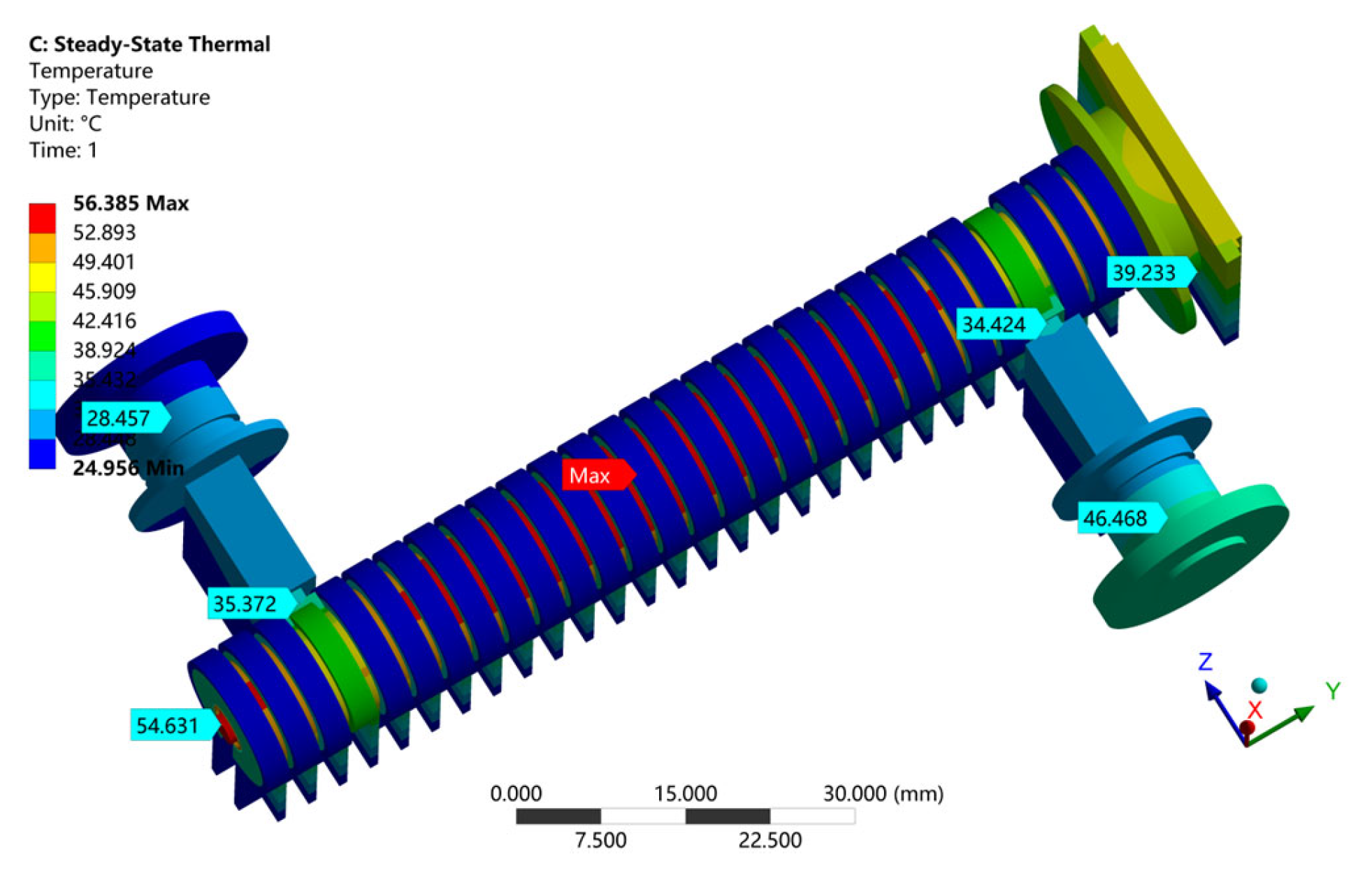
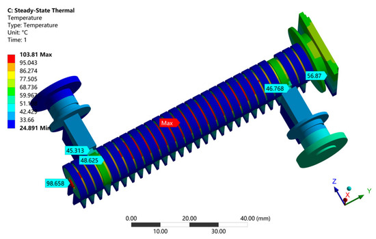
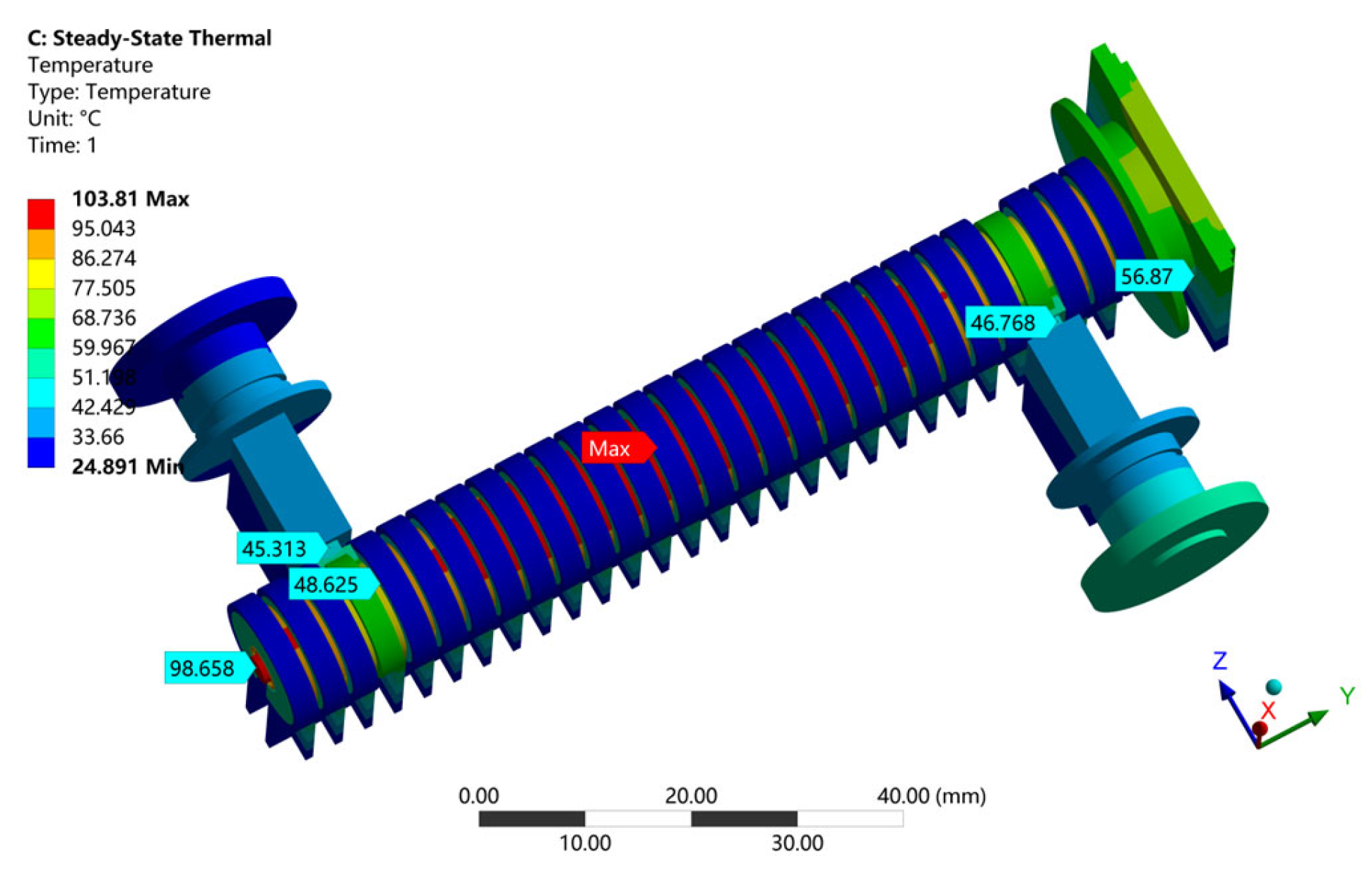
The simulated temperature of the SWS when oxygen-free copper was used as the material for the heat-conducting pillars of the support spacers is shown in Figure 10. The results indicate that the temperature decreased from 103 °C to 56 °C.
Figure 10.
The temperature of the optimized high-frequency system with heat-conducting pillars, which suggests a potential improvement in thermal power handling capability.
In the original structure, the heat generated by the slow-wave structure (SWS) and the output window must be conducted along the SWS, and then through the collector or electron gun, passing through multiple interfaces with high thermal contact resistance before finally reaching the heat sink (base plate). In the optimized design, the newly added oxygen-free copper pillars (thermal conductivity: 330 W/(m·K)) form multiple heat conduction paths directly to the base plate at 25 °C, so that most of the heat is dissipated through the new paths without passing through high-thermal-resistance regions.
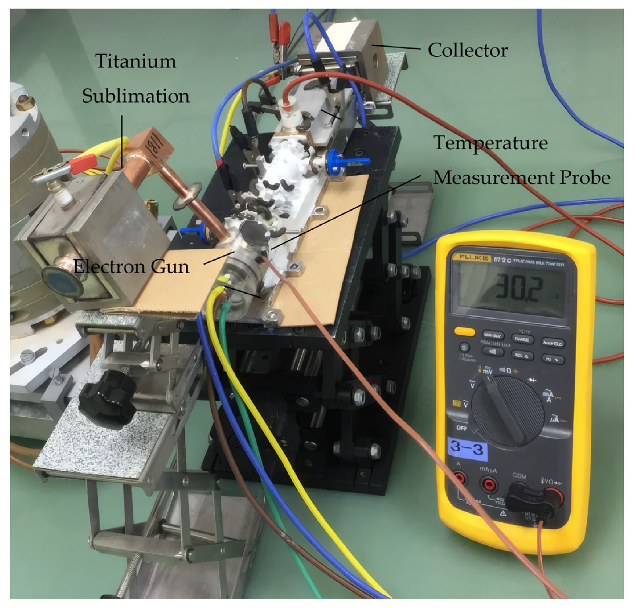
To investigate the increase in power capacity (thermal capacity) that the heat-conducting pillar can provide to the SWS, we incrementally increased the magnitude of the internal heat generation load on the SWS. It was found that when the internal heat generation load of the SWS was increased to 2.5 times the original value, the SWS reached a temperature of 103 °C, as shown in Figure 11. The testing of the temperature is shown in Figure 12, and a comparison between the tested temperature and the simulated temperature is shown in Table 4.
Figure 11.
The temperature of the optimized high-frequency system when the internal heat generation load increased to 2.5 times its original value, which suggests that this optimization could theoretically accommodate up to 2.5 times the original heat load.
Figure 12.
THz TWT surface temperature testing.
Table 4.
Comparison between the tested temperature and the simulated temperature.
Thus, it could be inferred that, from a purely thermal perspective, this optimized design approximately doubles the power capacity of the SWS.
It is important to emphasize that this represents a thermally inferred power capacity improvement, not a demonstrated increase in RF output power. Realizing such an improvement in practice would require addressing additional constraints:
- Beam interception: Higher beam power would increase electron interception losses, potentially offsetting thermal gains.
- RF breakdown: Higher electric fields at increased power levels could cause vacuum arcing.
- Magnetic saturation: The PPM focusing system’s performance might degrade at elevated temperatures.
- Vacuum integrity: Thermal expansion differences could compromise vacuum seals.
4.4. Design Generality and Transferability
The thermal optimization strategies demonstrated in this work are specific to the THz TWT architecture with PPM focusing. However, the underlying principles are transferable to other THz TWT configurations.
The principle of creating a direct thermal path between thermally vulnerable components (SWS or output window) and the heat sink (base plate) is universally applicable. The heat conduction structure can be adapted to the specific SWS or output window geometry while maintaining the same functional concept. The key requirement is that the conduction path material has high thermal conductivity (e.g., OFHC copper) and does not interfere with RF transmission.
5. Conclusions
To address the power limitation caused by thermal reliability issues in THz TWTs, we propose a thermal analysis method, as well as thermal optimization methods to enhance their power capacity. In the output window assembly, a novel thermal conduction structure was added between the output window and the base plate to provide a direct path for heat dissipation. The temperature of the optimized output window decreased from 81 °C to 34 °C. In the high-frequency system, novel heat-conducting pillars that passed through the slots of support spacers and the gaps between the magnets were added to connect the SWS to the base plate, thus forming a direct thermal conduction path. After OFHC copper heat-conducting pillars were added to the high-frequency system, the temperature of the SWS decreased from 103 °C to 56 °C, and this optimization of the high-frequency system doubled the power capacity of the SWS from a purely thermal perspective. This improvement in power capacity lays a solid foundation for the performance enhancement of terahertz vacuum electronic devices in applications such as wireless communication and imaging. Although the specific methods currently established are limited to the thermal optimization of specific structures, the underlying thermal management principles (identifying thermal bottlenecks and creating strategic heat conduction paths) constitute a transferable methodology applicable to various THz TWT architectures. Future research should focus on the full experimental validation of the thermally inferred power capacity improvement, and this thermal optimization methodology can be extended to THz TWTs operating at higher-frequency bands (e.g., 0.34 THz and 0.67 THz).
Supplementary Materials
The following supporting information can be downloaded at: https://www.mdpi.com/article/10.3390/electronics15051092/s1, Figure S1. The distribution of skewness after automatic meshing; Figure S2. The positions of tetrahedral meshes with a skewness of 0.75 or above; Figure S3. The distribution of skewness after mesh optimization.
Author Contributions
Conceptualization, T.W. and Y.G.; methodology, T.W.; validation, T.W., F.S. and J.Z.; formal analysis, Y.G.; investigation, T.W.; resources, Y.G.; data curation, S.F.; writing—original draft preparation, T.W.; writing—review and editing, S.F.; visualization, J.Z.; supervision, Y.G.; project administration, F.S. All authors have read and agreed to the published version of the manuscript.
Funding
This research received no external funding.
Data Availability Statement
The original contributions presented in this study are included in the article. Further inquiries can be directed to the corresponding author.
Conflicts of Interest
The authors declare no conflicts of interest.
Abbreviations
The following abbreviations are used in this manuscript:
| THz | Terahertz |
| TWT | Traveling Wave Tube |
| SWS | Slow-Wave Structure |
| FEA | Finite Element Analysis |
| DARPA | Defense Advanced Research Projects Agency |
| HiFIVE | High Frequency Integrated Vacuum Electronics |
| NGC | Northrop Grumman |
| ThzE | Terahertz Electronics |
| ViSAR | Video Synthetic Aperture Radar |
| OPTHER | Optical and THz Amplifier Research |
| AIR | Aerospace Information Research Institute |
| BVERI | Beijing Vacuum Electronics Research Institute |
| CAEP | China Academy of Engineering Physics |
| CAE | Computer-Aided Engineering |
References
- Paoloni, C.; Gamzina, D.; Letizia, R.; Zheng, Y.; Luhmann, N.C., Jr. Millimeter Wave Traveling Wave Tubes for the 21st Century. J. Electromagn. Waves Appl. 2021, 35, 567–603. [Google Scholar] [CrossRef] [Scilit]
- Kreischer, K.E.; Tucek, J.C.; Basten, M.A.; Gallagher, D.A. 220 GHz Power Amplifier Testing at Northrop Grumman. In Proceedings of the 2013 IEEE 14th International Vacuum Electronics Conference (IVEC), Paris, France, 21–23 May 2013; pp. 1–2. [Google Scholar]
- Tucek, J.C.; Basten, M.A.; Gallagher, D.A.; Kreischer, K.E. 670 GHz Power Amplifier Development at Northrop Grumman. In Proceedings of the 2011 Abstracts IEEE International Conference on Plasma Science, Chicago, IL, USA, 26–30 June 2011; p. 1. [Google Scholar]
- Tucek, J.C.; Basten, M.A.; Gallagher, D.A.; Kreischer, K.E. 0.850 THz Vacuum Electronic Power Amplifier. In Proceedings of the IEEE International Vacuum Electronics Conference, Monterey, CA, USA, 22–24 April 2014; pp. 153–154. [Google Scholar]
- Tucek, J.C.; Basten, M.A.; Gallagher, D.A.; Kreischer, K.E. Operation of a Compact 1.03 THz Power Amplifier. In Proceedings of the 2016 IEEE International Vacuum Electronics Conference (IVEC), Monterey, CA, USA, 19–21 April 2016; pp. 1–2. [Google Scholar]
- Basten, M.A.; Tucek, J.C.; Gallagher, D.A.; Kreischer, K.E. 233 GHz High Power Amplifier Development at Northrop Grumman. In Proceedings of the 2016 IEEE International Vacuum Electronics Conference (IVEC), Monterey, CA, USA, 19–21 April 2016; pp. 1–2. [Google Scholar]
- Kim, S.-H.; Fan, R.; Dominski, F. ViSAR: A 235 GHz Radar for Airborne Applications. In Proceedings of the 2018 IEEE Radar Conference (RadarConf18), Oklahoma City, OK, USA, 23–27 April 2018; pp. 1549–1554. [Google Scholar]
- Di Carlo, A.; Paoloni, C.; Brunetti, F.; Terranova, M.L.; Durand, A.; Marchesin, R.; Pham, K.; Krozer, V.; Fiorello, A.; Dispenza, M.; et al. The European Project OPTHER for the Development of a THz Tube Amplifier. In Proceedings of the 2009 IEEE International Vacuum Electronics Conference, Rome, Italy, 28–30 April 2009; pp. 100–101. [Google Scholar]
- Brunetti, F.; Cojocarua, C.-S.; de Rossi, A.; Di Carlo, A.; Dispenza, M.; Dolfi, D.; Durand, A.; Fiorello, A.; Gohier, A.; Guiset, P.; et al. European Research on THz Vacuum Amplifiers. In Proceedings of the 35th International Conference on Infrared, Millimeter, and Terahertz Waves, Rome, Italy, 5–10 September 2010; pp. 1–2. [Google Scholar]
- Liu, W.; Zhang, Z.; Liu, W.; Jin, Z.; Zhao, K.; Zhao, C.; Guo, X.; Zhang, Z.; Yin, S.; Zhang, Z. Demonstration of a High-Power and Wide-Bandwidth G-Band Traveling Wave Tube with Cascade Amplification. IEEE Electron Device Lett. 2021, 42, 593–596. [Google Scholar] [CrossRef] [Scilit]
- Pan, P.; Zhang, L.; Cui, H.; Feng, J. Terahertz Power Module Based on 0.34 THz Traveling Wave Tube. IEEE Electron Device Lett. 2022, 43, 816–819. [Google Scholar] [CrossRef] [Scilit]
- Hu, P.; Lei, W.; Jiang, Y.; Huang, Y.; Song, R.; Chen, H.; Dong, Y. Demonstration of a Watt-Level Traveling Wave Tube Amplifier Operating Above 0.3 THz. IEEE Electron Device Lett. 2019, 40, 973–976. [Google Scholar] [CrossRef] [Scilit]
- Lipari, G.; Muratore, A.; Paterna, G.; Traina, E.; Comparato, G.; Busacca, A.; Livreri, P.; Stivala, S. Design and Thermal Analysis of a Coupled-By-Rods Interaction Structure for Traveling-Wave Tubes. In Proceedings of the 2024 Joint International Vacuum Electronics Conference and International Vacuum Electron Sources Conference (IVEC + IVESC), Monterey, CA, USA, 22–25 April 2024; IEEE: Piscataway, NJ, USA, 2024; pp. 1–2. [Google Scholar]
- Mistry, C.; Guha, R.; Chakraborty, S.; Choudhury, A.R.; Alaria, M.K.; Ghosh, S.K. Design and Thermal Simulation of the H-Plane Waveguide Coupling for High Power Ku Band Helix TWT. In Proceedings of the 6th URSI Regional Conference on Radio Science—RCRS 2024, Uttarakhand, India, 22–25 October 2024; URSI—International Union of Radio Science: Bhimtal, India, 2024. [Google Scholar]
- Shin, Y.-M.; Baig, A.; Barnett, L.R.; Tsai, W.-C.; Luhmann, N.C. System Design Analysis of a 0.22-THz Sheet-Beam Traveling-Wave Tube Amplifier. IEEE Trans. Electron Devices 2012, 59, 234–240. [Google Scholar] [CrossRef] [Scilit]
- Bian, X.; Pan, P.; Du, X.; Song, B.; Zhang, L.; Cai, J.; Feng, J. Demonstration of a High Efficiency and Wide Band 30-W G-Band Continuous Wave Traveling Wave Tube. IEEE Electron Device Lett. 2024, 45, 1969–1972. [Google Scholar] [CrossRef] [Scilit]
- Ou, Y.; Liu, W.; Zhao, K.; Jin, Z.; Wei, Y.; Yang, Z.; Yin, W. Optimum Design of Electron Gun for 0.22-THz Traveling Wave Tubes. IEEE Trans. Microw. Theory Tech. 2022, 70, 307–314. [Google Scholar] [CrossRef] [Scilit]
- Xia, G.; Liu, W.; Zhou, D.; Jiao, A.; Li, H.; Lin, R. Design and Thermal-Mechanical Analysis of a 220 GHz TWT Collector. In Proceedings of the 2023 Cross Strait Radio Science and Wireless Technology Conference (CSRSWTC), Guilin, China, 10–13 November 2023; IEEE: Piscataway, NJ, USA, 2023; pp. 1–3. [Google Scholar]
- Xia, G.; Liu, W.; He, Y.; Li, H.; Zhou, D.; Jiao, A.; Lin, R. Design and Reliability Simulation of a G-Band Traveling-Wave Tube Multistage Depressed Collector with Curving Radiators Using FEA Method. IEEE Trans. Plasma Sci. 2024, 52, 3072–3078. [Google Scholar] [CrossRef] [Scilit]

Disclaimer/Publisher’s Note: The statements, opinions and data contained in all publications are solely those of the individual author(s) and contributor(s) and not of MDPI and/or the editor(s). MDPI and/or the editor(s) disclaim responsibility for any injury to people or property resulting from any ideas, methods, instructions or products referred to in the content. |
© 2026 by the authors. Licensee MDPI, Basel, Switzerland. This article is an open access article distributed under the terms and conditions of the Creative Commons Attribution (CC BY) license.