


Abstract
Dynamic wireless power transfer (DWPT) has attracted significant interest due to its ability to transfer power to moving electric vehicles. Most existing DWPT research focuses on vehicles traveling along fixed paths. However, modern warehouses increasingly employ indoor electric vehicles (IEVs), such as autonomous mobile robots, that move along non-fixed paths. Although several solutions have been proposed for large-area DWPT systems applicable to IEVs with non-fixed trajectories, these approaches are predominantly based on inductive DWPT. Such systems require a large number of densely arranged transmitting coils and expensive ferrite pads, resulting in high system cost. To the authors’ best knowledge, no published work has addressed large-area capacitive DWPT systems for IEVs moving along non-fixed paths. This paper aims to fill this research gap. The main novelty of this work is the first proposal of a capacitive DWPT system for lightweight IEVs operating along non-fixed paths. The feasibility of the proposed solution is validated through simulation studies conducted in PSIM. The simulation results demonstrate that the proposed DWPT system, employing an advanced transmitting-metal-plate activation strategy, can maintain an almost constant mutual capacitance, thereby ensuring a smooth output voltage at the receiving side for a moving IEV.
1. Introduction
With the rapid development of electrical technologies and automation, various indoor electric vehicles (IEVs) have become integral components of modern warehouses and industrial facilities. In warehouse environments, IEVs can be classified into two categories: fixed-path vehicles and non-fixed-path vehicles. An example of a fixed-path IEV is an automated guided vehicle (AGV), which follows a predefined path within the warehouse [1,2]. Examples of non-fixed-path IEVs, also referred to as flexible or dynamic-path vehicles, include autonomous mobile robots (AMRs), human-operated forklifts, and autonomous forklifts. AMRs and autonomous forklifts rely on dynamically planned paths, whereas human-operated forklifts follow paths planned by human operators [3,4].
IEVs typically require batteries to supply power to electric motors, sensors, and auxiliary devices. These batteries discharge over time and therefore must be recharged periodically, which leads to reduced warehouse productivity [5]. In addition, batteries increase the weight and size of IEVs, which can be problematic for compact platforms such as AMRs and AGVs. Moreover, batteries may pose safety risks, including fire or explosion, if inadequate battery management systems are used [6]. Consequently, measures should be taken to reduce battery size or, where possible, eliminate onboard batteries altogether.
One possible solution is the use of dynamic wireless power transfer (DWPT). This technology enables the charging of IEVs while they are in motion, thereby reducing battery size and cost while improving overall warehouse performance [5]. Furthermore, because DWPT can continuously transfer power to moving IEVs, the use of onboard batteries may be significantly reduced or even eliminated [7,8,9].
Numerous research studies have investigated DWPT for electric vehicles. Most of the existing literature (e.g., [5,7,8,9,10,11,12,13,14]) focuses on DWPT systems for indoor or outdoor electric vehicles operating along fixed paths, typically straight-line trajectories. In contrast, only a limited number of studies [15,16] address the application of DWPT to IEVs that move along non-fixed paths.
Despite the fact that the solutions proposed in [15,16] can be successfully applied to large-area DWPT systems for IEVs moving along non-fixed paths, they are based on inductive DWPT, which inherently has a significant disadvantage. Specifically, the requirement for a large number of densely placed transmitting coils and expensive large-area ferrite pads results in a very high system cost, even when planar transmitting coils are used. Therefore, it is important to propose significantly more cost-effective solutions for large-area DWPT systems for IEVs.
A significantly less expensive solution for DWPT can be based on capacitive DWPT, as this approach employs metal plates instead of coils with ferrite pads, which are considerably more costly than metal plates. Although several research papers have investigated capacitive DWPT (e.g., [5,13,14]), these works consider scenarios in which the IEV trajectory is fixed, typically along a straight line. Consequently, the proposed solutions are not applicable to IEVs operating along non-fixed paths.
Since, to the authors’ best knowledge, there are no published works addressing large-area capacitive DWPT for IEVs moving along non-fixed paths, this paper aims to fill this research gap. The main novelty of this work is the proposal of a capacitive DWPT system for IEVs operating along non-fixed paths for the first time. The feasibility of the proposed solution is validated through simulation studies.
The proposed capacitive DWPT system is intended for lightweight indoor IEVs (e.g., mobile robots such as [17]) with payload capacities up to 100 kg. These vehicles are typically constructed from non-conductive composite materials (e.g., reinforced plastics) and contain minimal metallic content, mainly limited to small components in motors and mechanical fasteners. However, IEVs with higher payload capacities typically contain a larger number of metallic components, such as structural metal profiles or even massive metal chassis (e.g., forklifts). The presence of large metallic objects, similarly to inductive WPT [18], may also pose a significant challenge in capacitive DWPT [19], resulting in reduced transferred power, lower efficiency, and increased thermal dissipation in the metallic parts of the IEV. Since the proposed DWPT system is intended for IEVs with minimal metallic content, the influence of large conductive bodies located near the capacitive coupling interface is not considered in this work and will be addressed in future studies.
This paper is partially based on our previously published conference paper [20]; however, it significantly extends the earlier work by providing additional analysis and simulation results.
2. Description of the Proposed Capacitive DWPT System for IEVs
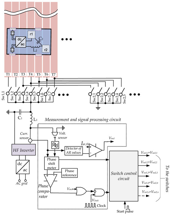
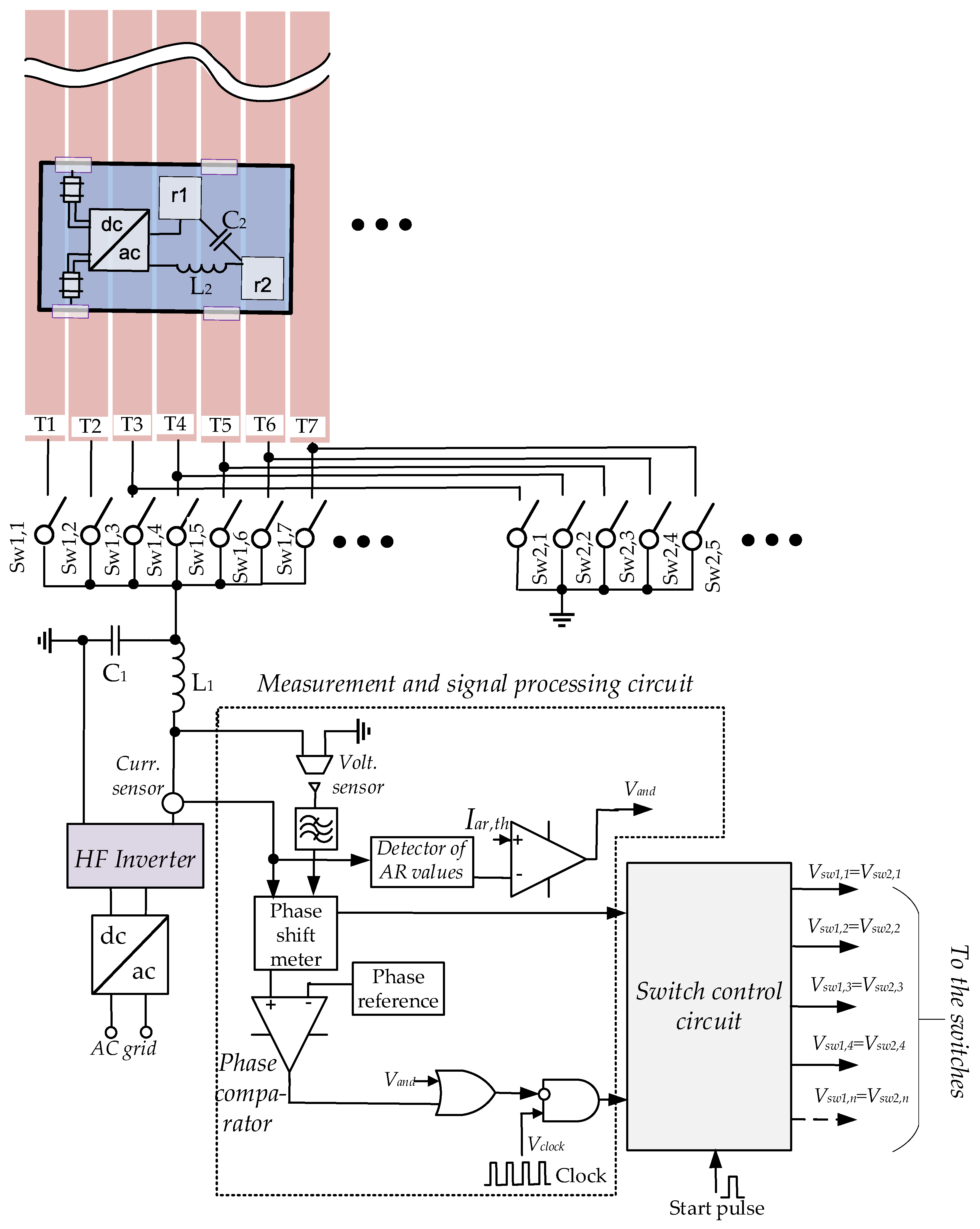
The proposed capacitive DWPT system for IEVs moving along non-fixed paths consists of transmitting metal plates, a grid-connected AC–DC converter, a high-frequency (HF) inverter with LC compensation, receiving metal plates with LC compensation, an AC–DC converter, and commutating switches for the transmitting metal plates together with their control circuitry (Figure 1).
Figure 1.
Simplified schematic diagram of the proposed DWPT system with N identical transmitting metal plates (only seven plates are shown for clarity).
As the HF inverter, classical topologies (e.g., Class E and soft-switching half-bridge inverters) employing GaN field-effect transistors (FETs) can be used. Due to the low capacitance between the transmitting and receiving plates (typically several pF to several tens of pF), the inverter switching frequency lies in the MHz range. Since WPT systems for warehouse mobile robots are considered industrial equipment, in this work a switching frequency of 6.78 MHz is used, which is permitted by CISPR 11 for industrial, scientific, and medical (ISM) applications in the MHz range.
As compensation at the transmitting side, a coil L1 and capacitor C1 are used in the DWPT system under development. At the receiving side, a coil L2 and capacitor C2 provide compensation. These classical compensation circuits are well suited for capacitive DWPT systems, as they significantly reduce the dependence of the output power on variations in mutual capacitance caused by IEV movement [21].
An approach for arranging transmitting metal plates in a DWPT system can be adapted from the concepts presented in [22,23], where static free-positioning capacitive WPT systems for electronic devices were proposed. However, the transmitting-side square metal plate structure described in [22] requires a large number of switches, making it unsuitable for the proposed DWPT system for IEVs. A more appropriate solution for the transmitting-side coupler is based on the use of long, parallel metal plates with a small separation distance, as proposed in [23]. This configuration will be adopted in the DWPT system under development (Figure 1).
The transmitting-side metal plates can be selectively connected to either power or ground terminals of the HF inverter by means of switches, as shown in Figure 1. The switches Sw1,n and Sw2,n must be bidirectional and can be implemented using two series-connected FETs. The number of switches that commutate the metal plates to the ground terminal of the HF inverter is two fewer than the number of switches that commutate the plates to the power terminal of the HF inverter. The clock frequency of the switch control circuit (fclock) should be selected such that the time required to turn on the next metal plate and to turn off the previous one is shorter than the time needed for the IEV to travel 1 mm. For example, assuming a maximum IEV speed of 2 m/s, fclock should be greater than 2 kHz.
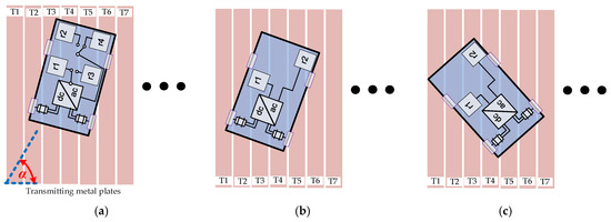
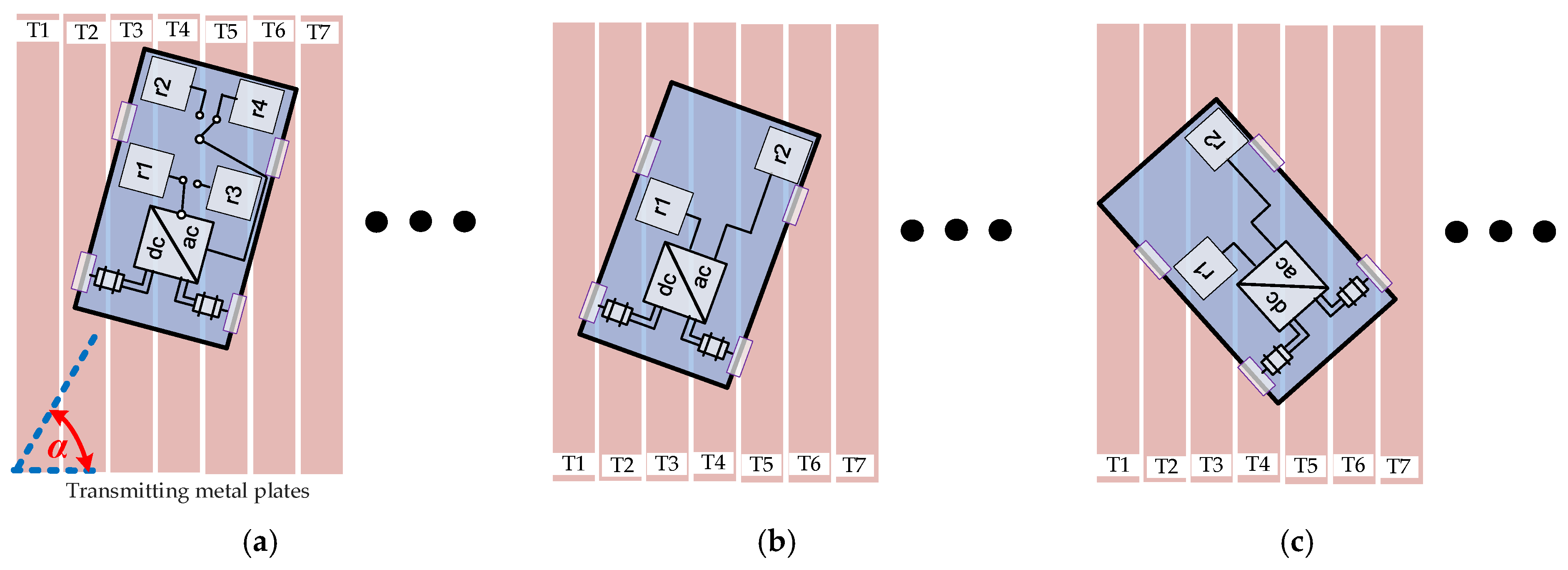
The layout of the receiving-side metal plates used in static capacitive WPT systems [22,23] is not feasible for the DWPT system under development. Therefore, to ensure smooth IEV movement in different directions without significant power pulsations, the configuration shown in Figure 2a is proposed. If the angle α is in the range of 0–90° (Figure 2a), metal plates r1 and r4 are activated (connected to the receiving-side converter with compensation). If the angle α is in the range of 90–180° (Figure 2a), metal plates r2 and r3 are activated. The on-board switch control must therefore be aware of the IEV position angle in order to activate the appropriate receiving-side metal plates. This information can be obtained from the IEV navigation system. Note that man-operated forklifts may not be equipped with a navigation system. Consequently, the configuration shown in Figure 2a may not be suitable for such vehicles or for other IEVs without navigation capabilities.
Figure 2.
The proposed different configurations of the receiving metal plates: (a) the most versatile configuration, but the most complex; (b) simple configuration, but prolonged movements in the range of α of 110–160° should be avoided; (c) simple configuration, the most extreme case when the mutual capacitance is very low.
The simplest layout of the receiving-side metal plates is shown in Figure 2b. In this configuration, neither receiving-plate commutating switches nor a navigation system are required. However, the configuration shown in Figure 2b has an inherent limitation: the output power may decrease significantly when 110° < α < 160°, due to the substantial reduction in the mutual capacitance, because in this angular range, the major part of both receiving plates is located above the same transmitting plate (e.g., T3) connected to the same inverter terminal. The most extreme case is illustrated in Figure 2c. Consequently, only very short-duration movements within this range of the positioning angle are acceptable. This limitation can be mitigated or eliminated by incorporating a supercapacitor on the receiving side.
The most important and complex part of the proposed DWPT system is the transmitting-plate commutating switch control circuit with the measurement and sensor signal processing circuit (Figure 1).
The measurement and sensor signal processing circuit performs phase-shift measurements, measures the average rectified (AR) value of the transmitting-side resonant tank current (Iar), and compares the measured values with predefined thresholds. The phase shift is measured between the transmitting-side resonant tank current (itank) and the fundamental harmonic of the tank input voltage (v1). The value of Iar is proportional to both the peak and RMS values of itank. The measurement and sensor signal-processing circuit assists the switch control circuit in determining which transmitting-side metal plates should be activated. It can be shown analytically, or verified through numerical simulations, that a higher mutual capacitance Cm between the receiving and transmitting metal plates results in a larger phase shift φ between itank and v1. To avoid noticeable degradation in output power and efficiency, Cm is allowed to decrease by no more than 15% from its nominal value determined at the maximum gap between the floor and the bottom of the IEV. Accordingly, the phase-shift threshold (φth) should be selected based on this criterion. Simulation results further indicate that φ may decrease moderately with an increase in the equivalent load resistance of the DWPT system. Consequently, at relatively high equivalent load resistances, φ may fall below φth even when Cm remains large. This situation can lead to incorrect selection of the transmitting-side metal plates to be energized. Therefore, an additional resonant-circuit parameter must be monitored. Simulation results show that, for a given Cm, a higher equivalent load resistance results in a lower Iar. Accordingly, the Iar threshold (Iar,th) should be selected based on the criterion that Cm is allowed to decrease by no more than 15% from its nominal value determined at the maximum gap between the floor and the bottom of the IEV. It should be noted that the switch control circuit is allowed to select the next combination of transmitting-side metal plates by commutating the correct switches if φ < φth and Iar > Iar,th.
At very low mutual capacitance values (Cm < 0.5 pF) or under no-coupling conditions, Iar becomes significantly higher and φ becomes significantly lower than their respective threshold values. In this case, the switch control circuit selects the next combination of switches to activate the appropriate transmitting-side metal plates. This strategy also helps to prevent large currents from circulating in the transmitting-side resonant tank for prolonged time intervals.
If the switches are not connected to the transmitting-side metal plates, only a very low current circulates in the resonant tank, because the C1 (Figure 1) value is selected such that resonance occurs when neighboring metal plates are connected to the inverter. When the metal plates are disconnected from the inverter, resonance does not occur, since the capacitance between neighboring metal plates is comparable to C1.
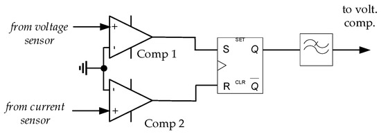
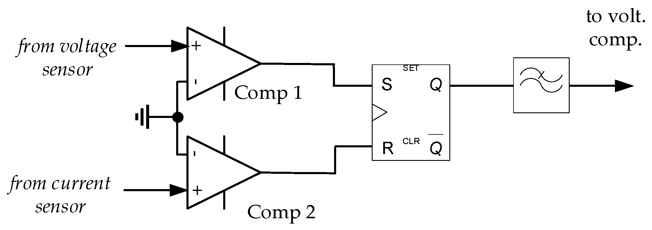
The phase shift φ can be measured using a single microcontroller (MCU), which can implement the transmitting-side switch control, the calculation of Iar and the comparison operations. However, accurate measurement of φ at a high frequency of 6.78 MHz is not supported by all low-cost MCUs. Therefore, an alternative approach based on classical analog–digital circuitry, as shown in Figure 3, can be used. In this approach, the output voltage of the low-pass filter is proportional to φ under steady-state conditions. Owing to the use of a second-order low-pass filter, the method exhibits high immunity to noise. Nevertheless, a trade-off exists between the response speed of the phase-shift measurement and noise immunity. This trade-off must be considered when selecting an appropriate cutoff frequency for the low-pass filter.
Figure 3.
One of the possible schematics of the phase shift meter of the proposed capacitive DWPT system for IEVs.
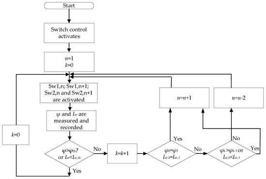
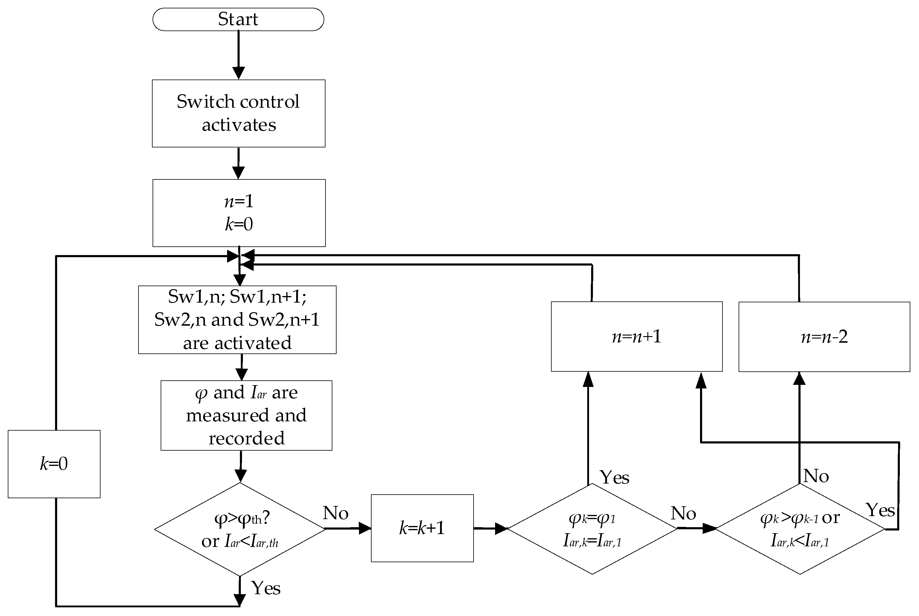
To clarify how the switch control circuit selects the appropriate transmitting-side metal plates to be energized in order to maximize Cm during IEV motion, the flowchart of the transmitting-metal-plate activation algorithm is shown in Figure 4. It should be noted that the switch control circuit is capable of energizing the appropriate transmitting-side metal plates regardless of the direction of IEV movement.
Figure 4.
A flowchart of the proposed IEV position detection and activation of the transmitting plates in the proposed capacitive DWPT system.
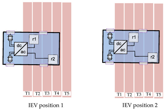
Let us consider an example with five long transmitting metal plates, where the IEV moves from left to right as illustrated in Figure 5. In this scenario, the flow of the transmitting-metal-plate activation algorithm is as follows:
Figure 5.
Illustration of the IEV in different positions when it moves from left to right.
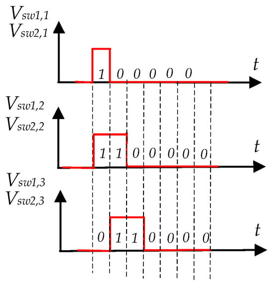
- When φ falls below φth, φk = φ1, Iar exceeds Iar,th and Iar,k = Iar,1, then n = 2, resulting in the activation of switches Sw1,2, Sw2,2, Sw1,3 and Sw2,3 (Figure 6). Thus, if the current IEV position is 2 (Figure 5), transmitting metal plates T2, T3, T4 and T5 are energized (T4 and T5 are connected to the inverter ground). The switches remain active as long as φ > φth or Iar < Iar,th.
- Again, when φ falls below φth, φk = φ1, Iar exceeds Iar,th and Iar,k = Iar,1, then n = 3, resulting in the activation of switches Sw1,3, Sw1,4, Sw2,3 and Sw2,4.
- The process is periodically repeated according to the flowchart shown in Figure 4.
Figure 6.
Output voltage waveforms and digital codes of the switch control circuit (if only five switches are used).
Let us consider an example with five long transmitting metal plates, where the IEV moves from right to left as illustrated in Figure 5. In this scenario, the flow of the transmitting-metal-plate activation algorithm is as follows:
- If the initial (static) IEV position corresponds to position 2 in Figure 5, then at the beginning of the process flow n = 1, k = 0 and switches Sw1,1, Sw2,1, Sw1,2 and Sw2,2 are activated. Since in this case Iar > Iar,th, n is incremented by 1, and the next combination of switches (Sw1,2, Sw1,3, Sw2,2 and Sw2,3) is selected.
- Since the IEV is now energized and Cm is large, the IEV starts to move from right to left.
- When the IEV reaches position 1 (Figure 5), φ falls below φth, φk = φ1, Iar exceeds Iar,th and Iar,k = Iar,1. According to Figure 4, this results in n = 3, leading to the activation of switches Sw1,3, Sw2,3, Sw1,4 and Sw2,4 (Figure 6). Since an incorrect combination of switches is selected, Iar > Iarth, φ < φth and k = 1, n is decreased by 2 and the correct combination of switches (Sw1,1, Sw2,1, Sw1,2 and Sw2,2) is now selected. The IEV continues to move from right to left.
- The process is periodically repeated according to the flowchart shown in Figure 4.
The voltage waveforms and digital codes shown in Figure 6 can be generated either by a single MCU or by conventional logic circuits to control the switches.
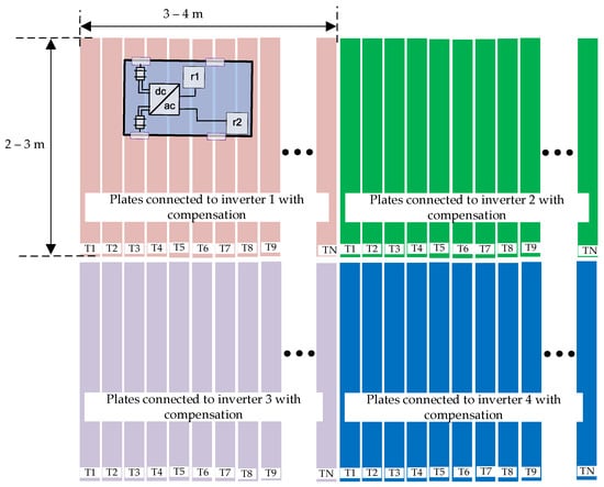
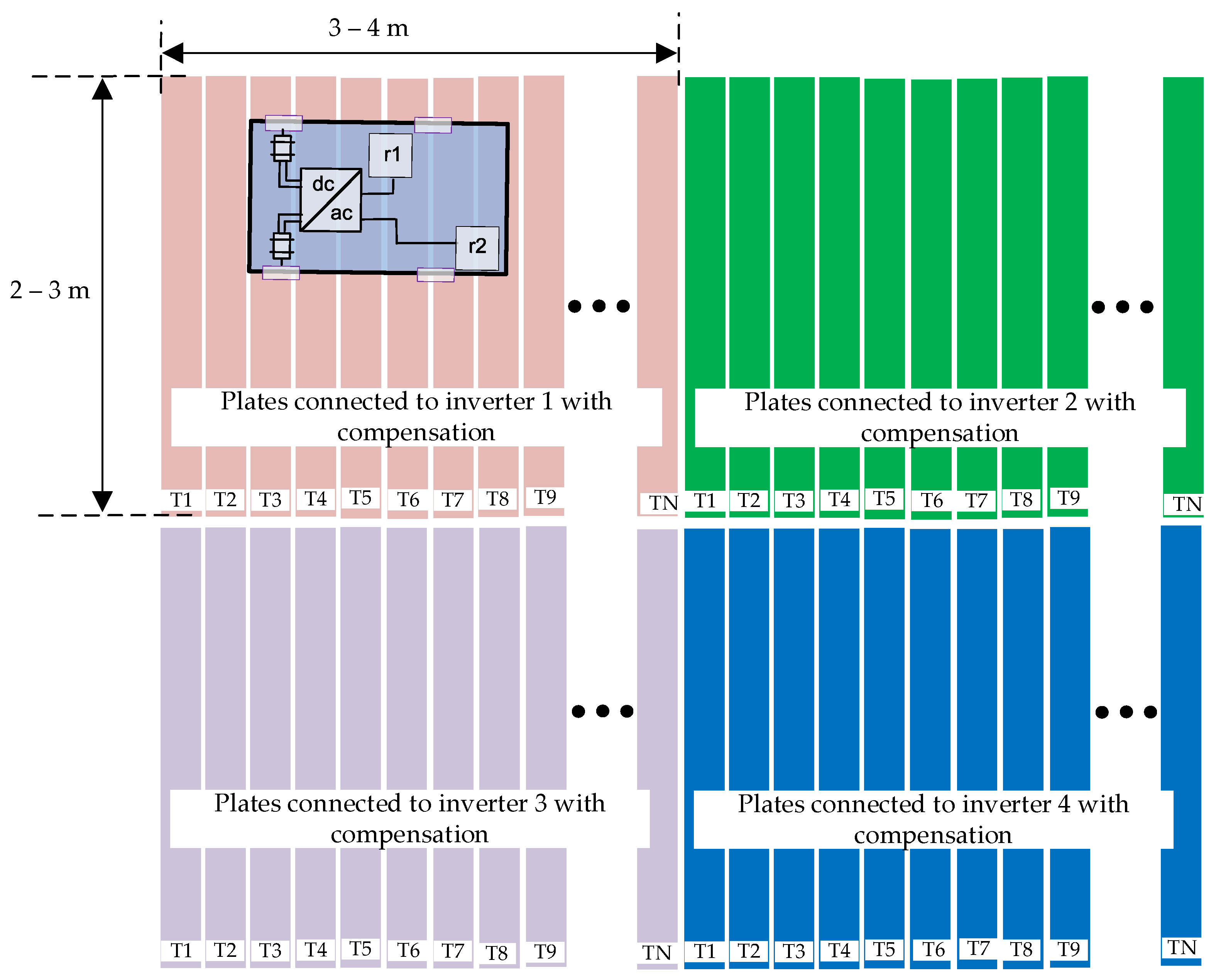
In practical wireless charging systems used in warehouses, a significantly larger number of long transmitting plates would be used. Furthermore, the structure would be segmented (Figure 7) to prevent excessive losses in long metal plates, reduce losses in long inverter connection conductors, and limit the parasitic capacitance between adjacent transmitting plates as seen by the inverter. Each segment would be energized by a separate inverter and could, for example, include 12 long transmitting metal plates of dimensions 20 cm × 3 m.
Figure 7.
Configuration of transmitting metal plates for a practical segmented large-area wireless charging system that can be used in a warehouse. Note that each segment has N identical transmitting metal plates.
Significant attention should be paid to large voltage spikes that may occur during transients caused by the fast turn-on and turn-off of the transmitting-plate-commutation switches, particularly under no-coupling conditions or when the mutual capacitance Cm is very low. These transients can pose a serious risk to the resonant tank capacitors, power switches, and even the receiving-side rectifier. Therefore, the transient voltage spikes must be mitigated, which can be achieved, for example, by slowing down the turn-on and turn-off processes of the plate-commutation switches.
It should be noted that fclock does not represent the plate switching frequency. Actual plate commutation occurs only when the mutual capacitance falls below a predefined threshold. Even at the maximum IEV speed of 2 m/s, the plate switching frequency is much lower than fclock (typically below several tens of hertz) and decreases further at lower vehicle speeds. Therefore, the transient losses that occur during the turn-on and turn-off of the plate-commutation switches contribute negligibly to the total system losses, since the transient duration is much shorter than the time interval between consecutive switching events while the IEV is in motion.
As mentioned in the Introduction, the proposed DWPT system is primarily intended for lightweight IEVs with minimal metallic content. A larger number of metallic components, such as structural metal profiles or massive metal chassis (e.g., in forklifts), introduces significant parasitic capacitances (e.g., between the metallic chassis and the coupling plates [19] that may become comparable to the mutual capacitance Cm. This can result in reduced transferred power and increased losses.
Nevertheless, as demonstrated in [19,24], capacitive DWPT can be successfully implemented without degradation in transferred power and efficiency even in the presence of a large metallic vehicle chassis. For example, in [19], by creating coupling circuit symmetry through the use of split inductor matching networks, the parasitic currents due to metallic chassis are significantly reduced and the parasitic capacitances are incorporated into the capacitive WPT mechanism. In [24], the metallic chassis itself is proposed as one of the coupler plates.
Considering the approaches presented in [19,24], we believe that, with appropriate modifications, the proposed capacitive DWPT system could also be adapted for non-fixed-path IEVs containing large metallic structures. This will be addressed in future work.
3. Validation of the Proposed DWPT System Through Simulations
3.1. Description of the Simulation Model
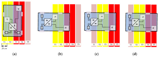
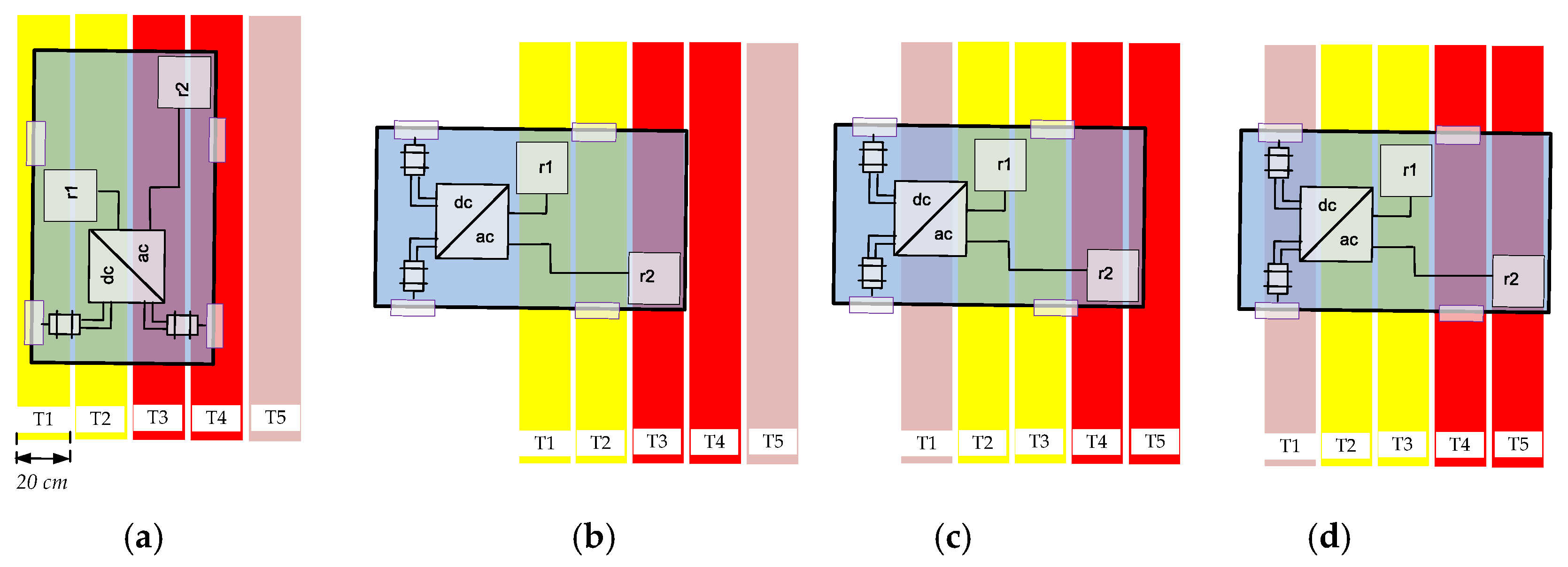
To demonstrate the usefulness of the proposed DWPT system and the transmitting-metal-plate activation circuit, a simple example is considered. In this example, five long transmitting metal plates are used (Figure 8). Each transmitting plate has a width of 20 cm and a length of 3 m, and the distance between adjacent transmitting plates is 1 cm. On the receiving side, two metal plates of size 20 × 20 cm are employed. The distance between the parallel transmitting and receiving plates is 1.2 cm. All metal plates are coated with a PVC layer with a relative permittivity of 2.7. Key electrical parameters of the simulated DWPT system are presented in Table 1.
Figure 8.
Different orientations of the IEV on the transmitting metal plates: (a) orientation of the IEV during motion parallel to the transmitting metal plates; (b–d) orientation of the IEV during motion perpendicular to the transmitting metal plates. Note: yellow and red colors indicate energized transmitting metal plates.
Table 1.
The main electrical parameters of the DWPT system.
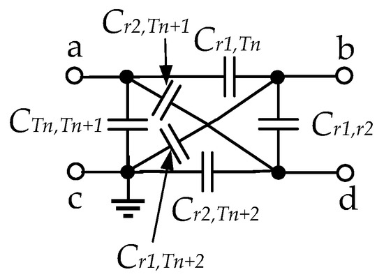
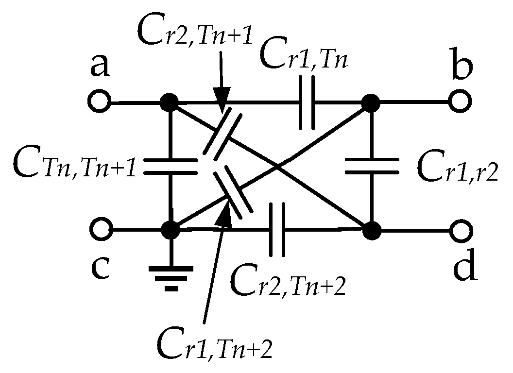
In order to create an accurate simulation model of the proposed DWPT system, an appropriate capacitive coupler model must be developed. The capacitive coupler model used in this study is shown in Figure 9. The values of the coupling capacitances between the receiving metal plate r1 and transmitting metal plate Tn (Cr1,Tn), and between the receiving plate r2 and transmitting plate Tn+2 (Cr2,Tn+2) were obtained using the 3D electromagnetic simulation software Ansys HFSS ver. 2025 R2 (Figure 10). Parasitic capacitance between adjacent metal plates connected to different terminals of the inverter output, CTn,Tn+1 = 100.3 pF. Parasitic capacitance between the receiving metal plates r1 and r2, Cr1,r2 = 1.3 pF.
Figure 9.
Model of the capacitive coupler used in the simulations. It should be noted that the total coupling capacitance Cm,n = (Cr1,Tn · Cr2,Tn+2 − Cr1,Tn+2 · Cr2,Tn+1)/(Cr1,Tn + Cr2,Tn+2 + Cr1,Tn+2 + Cr2,Tn+1) [13]. It should also be noted that the capacitances between nodes a and d (Cr2,Tn+1), and between nodes b and c (Cr1,Tn+2), are parasitic capacitances that must be included in the model, as they are not negligible.
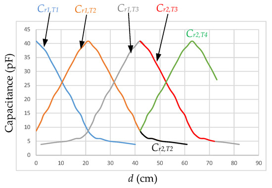
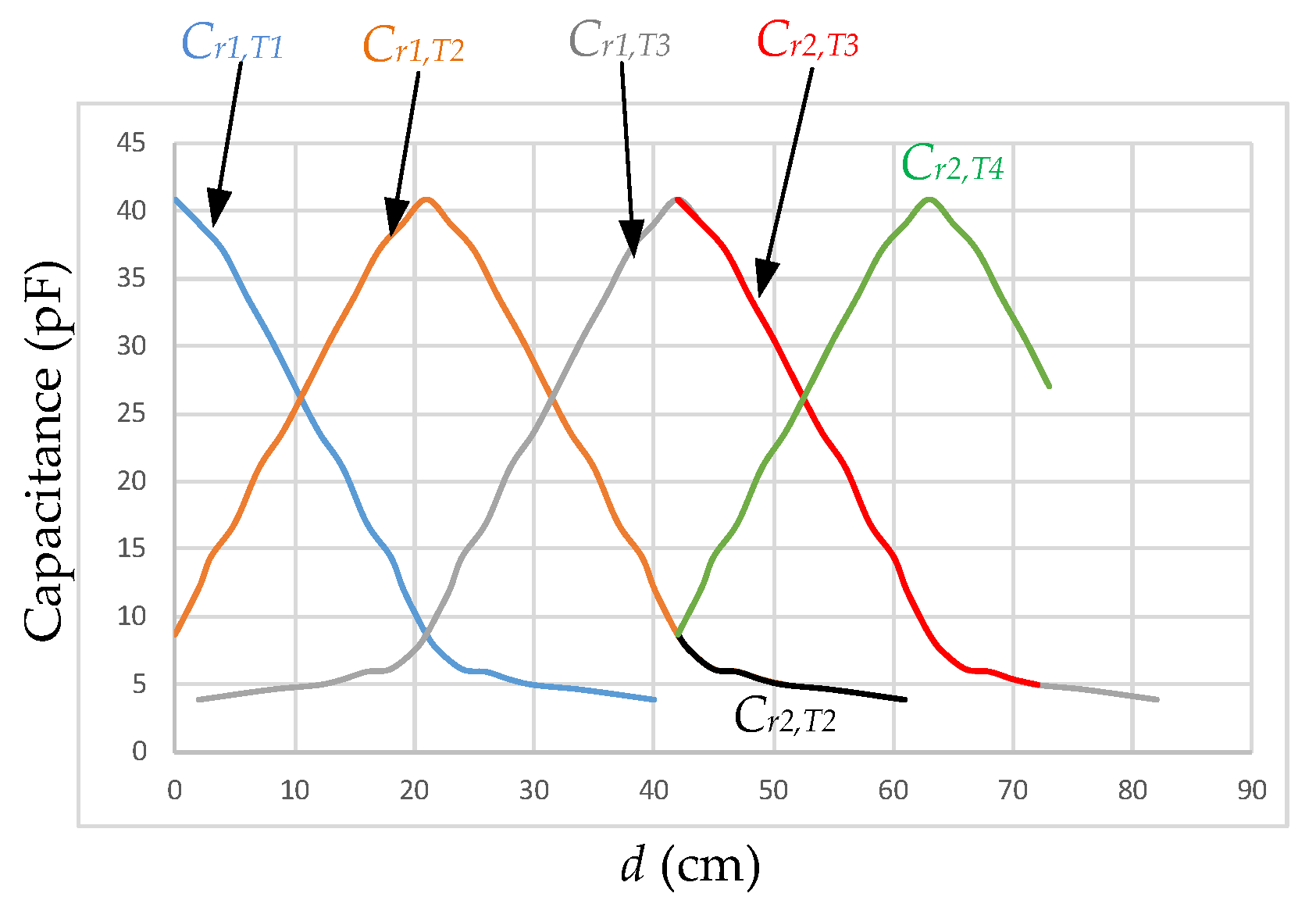
Figure 10.
Capacitances Cr1,Tn and Cr2,Tn+2 as functions of the distance (d) between the centers of plates r1 or r2 and the centerline of the first (leftmost) plate (see Figure 8), for the case when the IEV moves from left to right. It should be noted that the results were obtained using Ansys HFSS (ver. 2025 R2), considering only one transmitting plate and one receiving plate.
As mentioned in the Introduction, the influence of large conductive bodies located near the capacitive coupling interface is not considered in this work, because the proposed capacitive DWPT system is intended for lightweight indoor IEVs with a limited number of small metallic parts. Consequently, parasitic capacitances arising from the IEV’s conductive parts are neglected in the analysis.
The inverter switching frequency fsw is 6.78 MHz. L1 is chosen to be . C1 can be calculated using the Thomson resonance formula as follows:
To achieve optimal performance, C1 was selected as 171 pF so that the L1C1 resonant tank is slightly detuned when Cm = 0. The receiving-side resonant tank coil inductance L2 is chosen to be equal to L1. Since the receiving-side compensation capacitor is connected in parallel with the parasitic capacitance Cr1,r2, the equivalent capacitance in the simulation model (Figure 10) is represented by C2 which incorporates Cr1,r2 and has a value of 272 pF.
The clock frequency of the switch control circuit is set to 5 kHz.
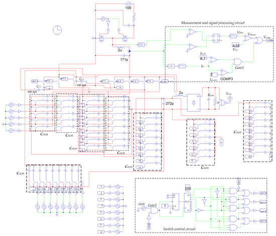
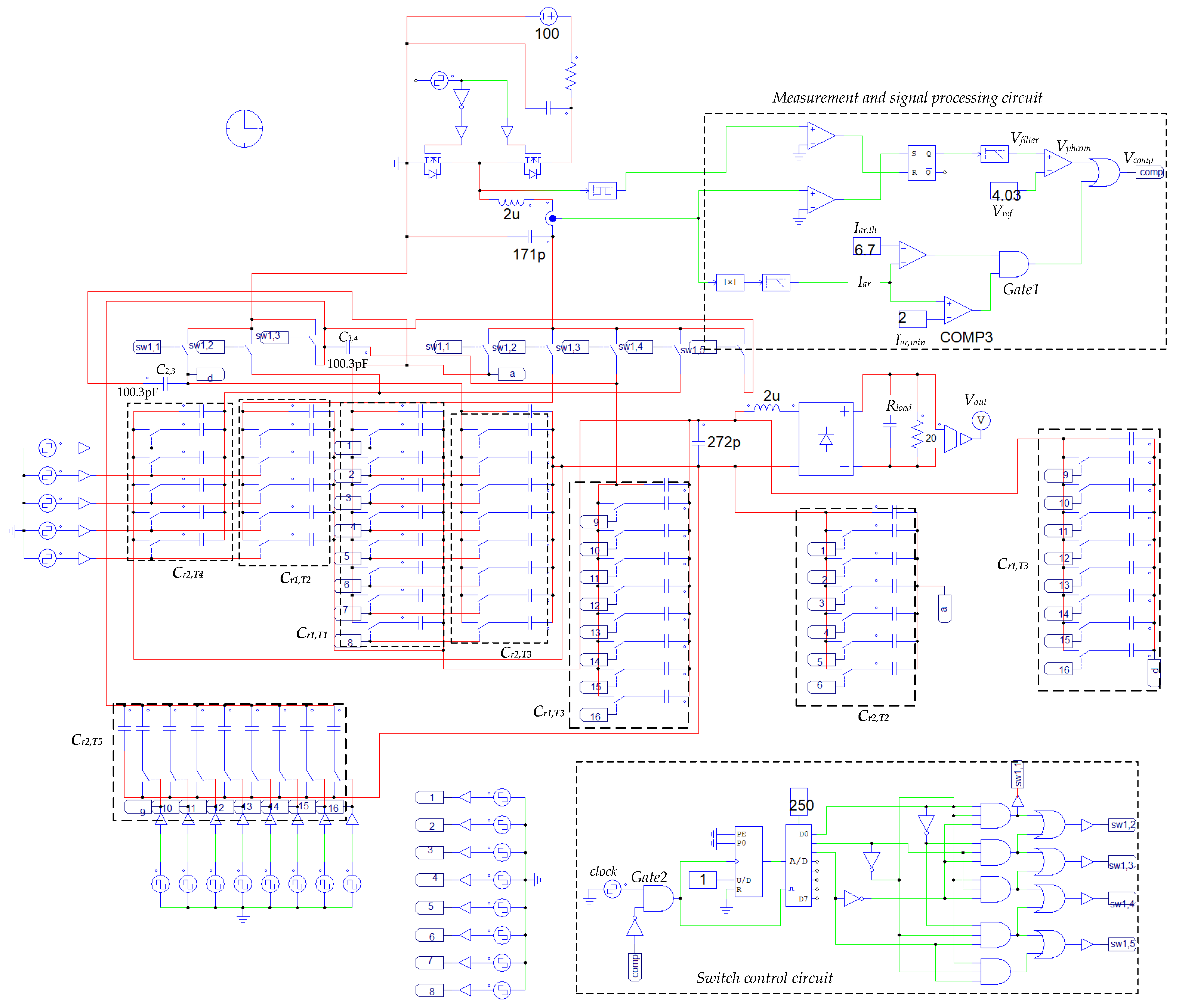
The simulation model of the proposed DWPT system using five transmitting metal plates is shown in Figure 11. The model can be easily scaled to accommodate a significantly larger number of transmitting metal plates, if required.
Figure 11.
The model of the proposed capacitive DWPT system if five transmitting-side metal plates are used.
To ensure smooth operation of the proposed DWPT system over a wide range of equivalent load resistances (20–60 Ω), the reference voltage of the phase meter comparator, Vref, is set to 4.03 V (Figure 11) and Iar,th = 6.7 A. When Cm is lower than 85% of its nominal value (determined at the maximum gap between the floor and the bottom of the IEV), the output voltage of the second-order filter falls below Vref, while Iar exceeds Iar,th. Consequently, both the phase meter comparator output voltage Vphcom and Iar comparator output voltage will be close to 0, allowing clock pulses to pass through the AND gate (Gate 2) of the switch control circuit to the counter inputs. When Cm becomes very small or coupling is absent, Iar > Iar,th, causing the counter to increment (or decrement) and thereby change the combination of active switches.
The switch control circuit model consists of a digital counter, a demultiplexer and some logic gates (Figure 11). It generates pulses (or digital codes) according to Figure 6. Since a start pulse is not used in the switch control circuit, the initial activation of T1–T4 can occur only when the clock signal passes through Gate 2. For this purpose, comparator COMP3 (Figure 11) is used. Its output is low when Iar < 2 A, which corresponds to the condition when the inverter is disconnected from all transmitting plates.
Under dynamic operating conditions, the capacitances between the receiving and the corresponding transmitting metal plates vary continuously. Therefore, each coupling capacitance is modeled as a matrix of parallel-connected capacitors controlled by switches. Values of Cr1,Tn and Cr2,Tn+2 are taken from Figure 10. This matrix-based approach is adopted because simulations using the classical integrator- and controlled-voltage-source-based variable capacitor model was found to be numerically unstable.
The MOSFETs of the inverter, as well as the resonant elements (capacitors and inductors), include the main non-idealities and are modeled with typical values of parasitic resistances.
3.2. Simulation Results and Discussion
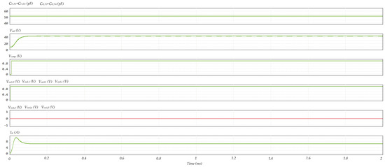
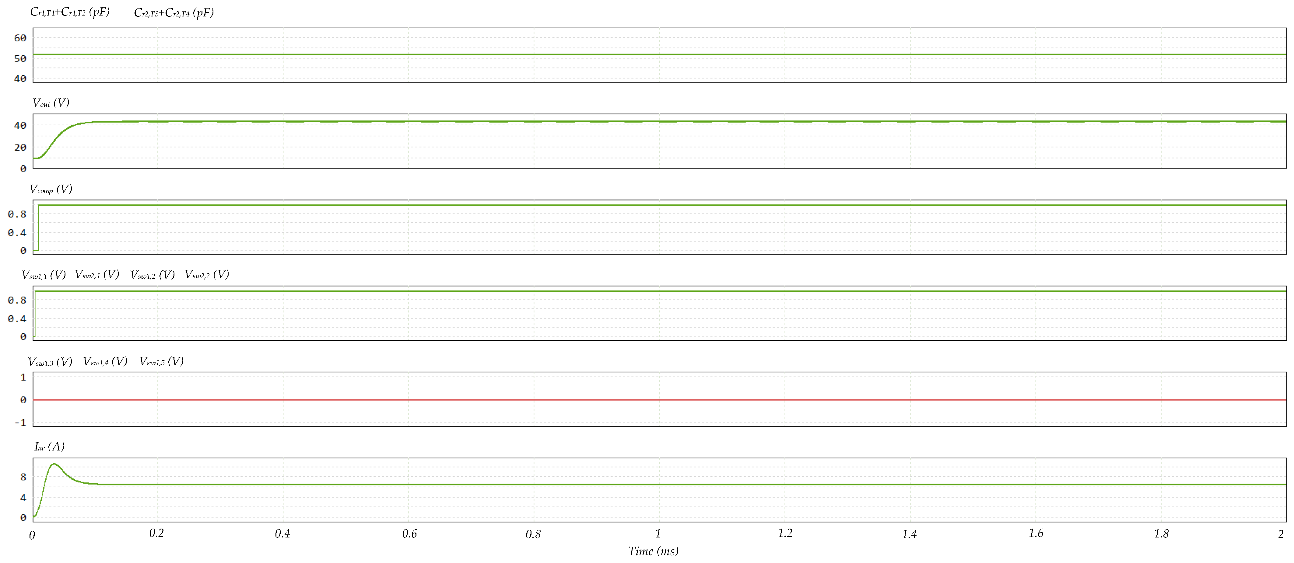
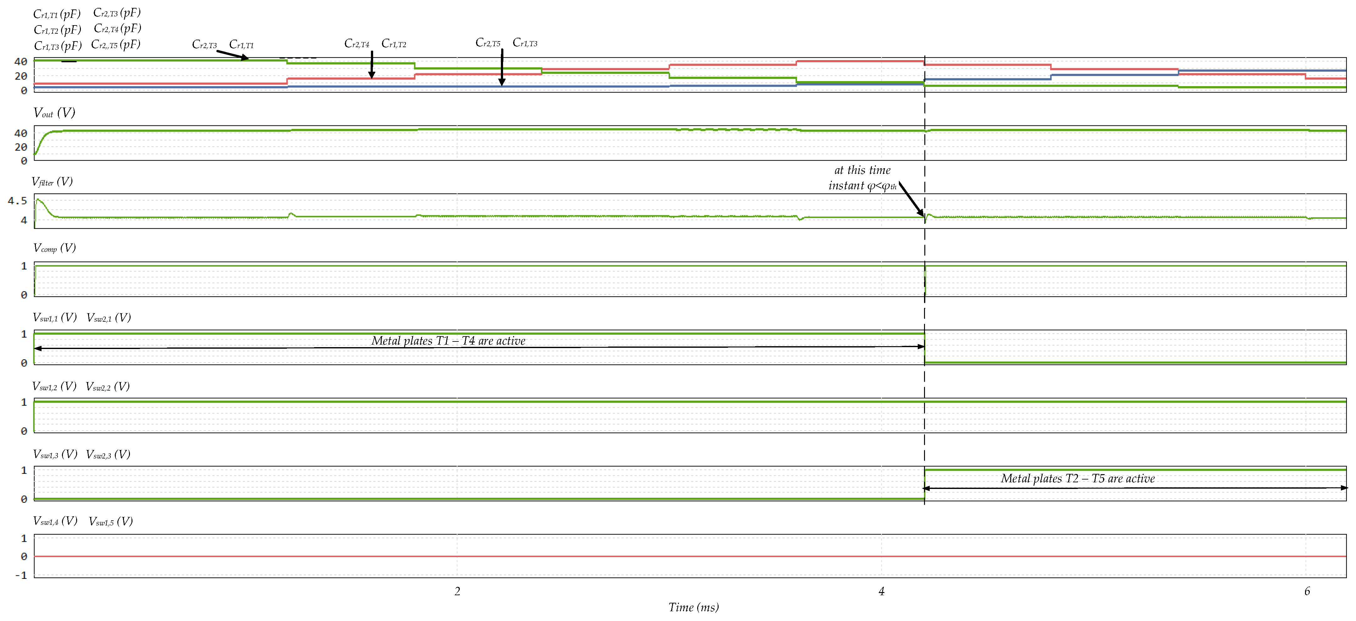
The main simulation results are presented in Figure 12, Figure 13 and Figure 14. As an illustrative example, let us consider the case shown in Figure 8a. Initially, clock pulses from the switch control circuit pass through Gate 2, causing the counter to advance to the next state (Figure 12). As a result, switches Sw1,1, Sw1,2, Sw2,1, and Sw2,2 are activated, which in turn activates the transmitting metal plates T1, T2, T3, and T4. After a short transient interval, the output voltage of the phase meter second-order filter, Vfilter, exceeds Vref. Consequently, the output of OR gate (Figure 11) switches to logic high (Figure 12, Vcomp). This blocks clock pulses at Gate 2, preventing further changes in the counter state. As a result, the output voltage Vout remains smooth, without observable drops, and switches Sw1,1, Sw1,2, Sw2,1 and Sw2,2 remain activated (Figure 12), while all other switches remain turned off.
Figure 12.
Simulated waveforms of the proposed DWPT system when the IEV moves parallel to the transmitting metal plates (as shown in Figure 8a).
Figure 13.
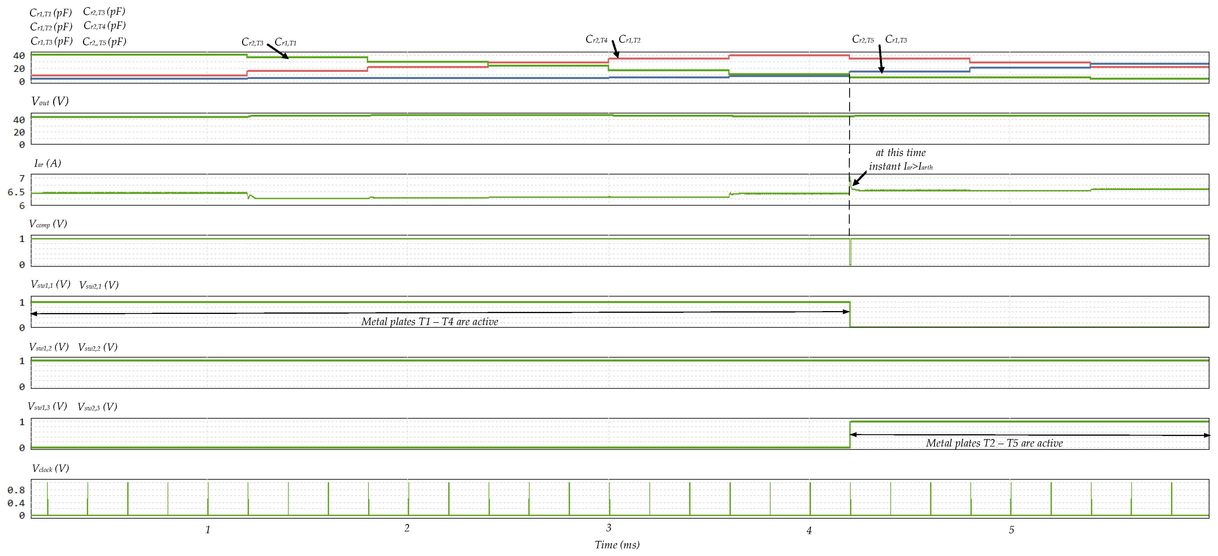
Simulated waveforms of the proposed DWPT system when the IEV moves perpendicular to the transmitting metal plates (as shown in Figure 8b). Notes: the equivalent load resistance is 20 Ω; the rate of change of Crk,Tn is at least 20 times slower than that assumed in the simulations, given that the maximum speed of IEVs is typically below 2 m/s.
Figure 14.
Simulated waveforms of the proposed DWPT system when the IEV moves perpendicular to the transmitting metal plates (as shown in Figure 8b). Note: the equivalent load resistance is 60 Ω.
If the initial position of the IEV is as shown in Figure 8b, the second clock pulse activates the switches Sw1,1, Sw1,2, Sw2,1 and Sw2,2 through the counter and demultiplexer. After a short transient, Vout reaches a value close to its nominal level (Figure 13). When Vfilter > Vref = 4.03 V, Gate 1 output Vcomp becomes logic 1, and subsequent clock pulses are blocked from the counter. As Cr1,T2 and Cr2,T4 drop below 36 pF, Vfilter for a short time drops below Vref (Figure 13), allowing a clock pulse to pass through Gate 2 to the counter. Consequently, Sw1,2, Sw1,3, Sw2,2 and Sw2,3 are activated. Vout remains nearly constant, varying only slightly within the range of 42.5–45 V, even when the IEV moves perpendicular to the transmitting metal plates (Figure 12). The switches Sw1,2, Sw1,3, Sw2,2 and Sw2,3 remain activated (Figure 13), while other switches (Sw1,4 and Sw1,5) remain off. The process of activating the correct transmitting-side metal plates would periodically repeat if additional plates were present.
Simulations with an equivalent load resistance of 60 Ω also show positive results, as the correct combination of switches is selected to ensure nearly constant Vout. The output voltage varying only slightly within the range of 45–47.5 V (Figure 14). Simulations with other load resistance values show that the output voltage remains within ±5.5% of its nominal value. If necessary, the accuracy of the output voltage can be further improved by using a voltage regulator.
Transient spike and loss analysis was also performed in PSIM. The transient study showed that rapid commutation of the plate-commutating switches, especially under no-coupling conditions, leads to significant voltage spikes (up to 1.5 kV) across the resonant tank capacitors C1 and C2, mainly during turn-on. By increasing the turn-on and turn-off times of the switches from 20 ns to 140 ns, the peak voltage was significantly reduced (to below 1 kV). Therefore, in practical implementation, the switches should be turned on and off with a reduced slew rate.
Transient loss analysis showed that the contribution of transient losses in the plate-commutating switches is negligible, accounting for only about 2% of the total losses of the switches. This is because the transient duration (<20 µs) is much shorter than the interval between two switching events. The simulated overall system efficiency including transient losses was only 0.2% lower than the efficiency calculated without considering transient effects.
It should be noted that the model also supports IEV motion from right to left. In this case, a logic 0 must be applied to the counter’s up/down (U/D) input.
4. Conclusions
This paper proposes, for the first time, a capacitive dynamic wireless power transfer system designed for lightweight indoor electrical vehicles with minimal metallic content, capable of operating along non-fixed paths. The simulation results demonstrate that the system, employing an advanced transmitting-metal-plate activation strategy, can maintain an approximately constant mutual capacitance, thereby ensuring a nearly constant output voltage at the receiving side for a moving indoor electrical vehicle in multiple directions. Future work will focus on the experimental validation of the proposed capacitive dynamic wireless power transfer system, as well as on extending its application to non-fixed-path indoor electrical vehicles (e.g., forklifts) with large metallic chassis and structural profiles.
Author Contributions
Conceptualization, D.S.; methodology, D.S.; software and design, E.D.; validation, E.D. and D.S.; formal analysis, J.Z.; data curation, J.Z.; writing—original draft preparation, D.S.; writing—review and editing, O.H.; visualization, J.Z.; supervision, J.Z.; project administration, J.Z. All authors have read and agreed to the published version of the manuscript.
Funding
This work has been supported by grant No. RTU-ZG-2024/1-0027 under the EU Recovery and Resilience Facility funded project No. 5.2.1.1.i.0/2/24/I/CFLA/003 “Implementation of consolidation and management changes at Riga Tech. University, Liepaja University, Rezekne Academy of Technology, Latvian Maritime Academy and Liepaja Maritime College for the progress towards excellence in higher education, science, and innovation”.
Data Availability Statement
The data of our study are available upon request.
Conflicts of Interest
The authors declare no conflicts of interest.
References
- AGV Navigation: Methods, Comparison, Pros and Cons—Illustrated Guide. Available online: https://www.agvnetwork.com/types-of-navigation-systems-automated-guided-vehicles (accessed on 18 February 2026).
- Fragapane, G.; Koster, R.D.; Sgarbossa, F.; Strandhagen, J.O. Planning and Control of autonomous mobile robots for intralogistics: Literature review and research agenda. Eur. J. Oper. Res. 2021, 294, 405–442. [Google Scholar] [CrossRef] [Scilit]
- Fraifer, M.A.; Coleman, J.; Maguire, J.; Trslić, P.; Dooly, G.; Toal, D. Autonomous Forklifts: State of the Art—Exploring Perception, Scanning Technologies and Functional Systems—A Comprehensive Review. Electronics 2025, 14, 153. [Google Scholar] [CrossRef] [Scilit]
- Aremu, M.B.; Ahmed, G.; Elferik, S.; Saif, A.-W.A. Autonomous Mobile Robot Path Planning Techniques—A Review: Metaheuristic and Cognitive Techniques. Robotics 2026, 15, 23. [Google Scholar] [CrossRef] [Scilit]
- Makhdoom, R.; Maji, S.; Sinha, S.; Etta, D.; Afridi, K. Multi-MHz in-Motion Capacitive Wireless Power Transfer System for Mobile Robots. In Proceedings of the 2022 Wireless Power Week (WPW), Bordeaux, France, 5–8 July 2022; IEEE: Hoboken, NJ, USA, 2022; pp. 1–5. [Google Scholar] [CrossRef] [Scilit]
- Kong, L.; Li, C.; Jiang, J.; Pecht, M.G. Li-Ion Battery Fire Hazards and Safety Strategies. Energies 2018, 11, 2191. [Google Scholar] [CrossRef] [Scilit]
- Stepins, D.; Sokolovs, A.; Zakis, J. Dynamic Resonant-Inductive Wireless Power Transfer System for Automated Guided Vehicles with Reduced Number of Position Sensors. Electronics 2024, 13, 2377. [Google Scholar] [CrossRef] [Scilit]
- Patil, D.; Miller, J.M.; Fahimi, B.; Balsara, P.T.; Galigekere, V.A. Coil Detection System for Dynamic Wireless Charging of Electric Vehicle. IEEE Trans. Transp. Electrif. 2019, 5, 988–1003. [Google Scholar] [CrossRef] [Scilit]
- Vincent, D.; Huynh, P.S.; Azeez, N.A.; Patnaik, L.; Williamson, S.S. Evolution of Hybrid Inductive and Capacitive AC Links for Wireless EV Charging—A Comparative Overview. IEEE Trans. Transp. Electrif. 2019, 5, 1060–1077. [Google Scholar] [CrossRef] [Scilit]
- Patil, D.; McDonough, M.K.; Miller, J.M.; Fahimi, B.; Balsara, P.T. Wireless Power Transfer for Vehicular Applications: Overview and Challenges. IEEE Trans. Transp. Electrif. 2018, 4, 3–37. [Google Scholar] [CrossRef] [Scilit]
- Sakayanagi, Y.; Togawa, S.; Konagaya, K.; Kuwahara, Y. Wireless power transmission for a traveling mobility scooter. In Proceedings of the 2016 IEEE Wireless Power Transfer Conference (WPTC), Aveiro, Portugal, 5–6 May 2016; IEEE: Hoboken, NJ, USA, 2016; pp. 1–3. [Google Scholar] [CrossRef] [Scilit]
- Simonazzi, M.; Sandrolini, L.; Mariscotti, A. Receiver-Coil Location Detection in a Dynamic Wireless Power Transfer System for Electric Vehicle Charging. Sensors 2022, 22, 2317. [Google Scholar] [CrossRef] [Scilit]
- Zhang, Y.; Chen, S.; Li, X.; Yan, Z.; Tang, Y. A Compact Dynamic Wireless Power Transfer System via Capacitive Coupling Achieving Stable Output. In Proceedings of the 2020 IEEE 9th International Power Electronics and Motion Control Conference (IPEMC2020-ECCE Asia), Nanjing, China, 2 December 2020; pp. 3269–3275. [Google Scholar] [CrossRef] [Scilit]
- Bae, H.; Park, S. Design of Four-Plate Parallel Dynamic Capacitive Wireless Power Transfer Coupler for Mobile Robot Wireless-Charging Applications. Appl. Sci. 2025, 15, 823. [Google Scholar] [CrossRef] [Scilit]
- Al Mahmud, S.A.; Panhwar, I.; Jayathurathnage, P. Large-Area Free-Positioning Wireless Power Transfer to Movable Receivers. IEEE Trans. Ind. Electron. 2022, 69, 12807–12816. [Google Scholar] [CrossRef] [Scilit]
- Al Mahmud, S.A.; Liu, Y.; Ha-Van, N.; Jayathurathnage, P.; Tretyakov, S.A. Planar Free-Positioning Wireless Power Transfer System for Industrial and Automotive Robotic Applications. IEEE Open J. Ind. Electron. Soc. 2025, 6, 1152–1162. [Google Scholar] [CrossRef] [Scilit]
- Mobile Robot MP-400 Data Sheet. Available online: https://www.neobotix-robots.com/products/mobile-robots/mobile-robot-mp-400 (accessed on 22 February 2026).
- Niu, S.; Zhao, Q.; Chen, H.; Niu, S.; Jian, L. Noncooperative Metal Object Detection Using Pole-to-Pole EM Distribution Characteristics for Wireless EV Charger Employing DD Coils. IEEE Trans. Ind. Electron. 2024, 71, 6335–6344. [Google Scholar] [CrossRef] [Scilit]
- Sinha, S.; Kumar, A.; Regensburger, B.; Afridi, K.K. A New Design Approach to Mitigating the Effect of Parasitics in Capacitive Wireless Power Transfer Systems for Electric Vehicle Charging. IEEE Trans. Transp. Electrif. 2019, 5, 1040–1059. [Google Scholar] [CrossRef] [Scilit]
- Stepins, D.; Zakis, J.; Kolesnikovs, K.; Khandakji, K.; Dereviagin, E. Different Solutions for Dynamic Wireless Power Transfer to Indoor Autonomous Mobile Robots Moving along Arbitrary Path. In Proceedings of the 2025 7th Global Power, Energy and Communication Conference (GPECOM), Bochum, Germany, 11–13 June 2025; pp. 104–107. [Google Scholar] [CrossRef] [Scilit]
- Lu, F.; Zhang, H.; Mi, C. A Review on the Recent Development of Capacitive Wireless Power Transfer Technology. Energies 2017, 10, 1752. [Google Scholar] [CrossRef] [Scilit]
- Liu, C.; Hu, A.P.; Wang, B.; Nair, N. A capacitively coupled contactless matrix charging platform with soft switched transformer control. IEEE Trans. Ind. Electron. 2013, 60, 249–260. [Google Scholar] [CrossRef] [Scilit]
- Yuan, H.; Liang, C.; Zhang, R.; Ruan, Z.; Zhou, Z.; Yang, A.; Wang, X.; Rong, M. A Novel Anti-Offset Interdigital Electrode Capacitive Coupler for Mobile Desktop Charging. IEEE Trans. Power Electron. 2023, 38, 4140–4151. [Google Scholar] [CrossRef] [Scilit]
- Lu, F.; Zhang, H.; Mi, C. A Two-Plate Capacitive Wireless Power Transfer System for Electric Vehicle Charging Applications. IEEE Trans. Power Electron. 2018, 33, 964–969. [Google Scholar] [CrossRef] [Scilit]

Disclaimer/Publisher’s Note: The statements, opinions and data contained in all publications are solely those of the individual author(s) and contributor(s) and not of MDPI and/or the editor(s). MDPI and/or the editor(s) disclaim responsibility for any injury to people or property resulting from any ideas, methods, instructions or products referred to in the content. |
© 2026 by the authors. Licensee MDPI, Basel, Switzerland. This article is an open access article distributed under the terms and conditions of the Creative Commons Attribution (CC BY) license.