


Abstract
This paper proposes chattering reduction using various switching functions in the sliding mode control (SMC) method for permanent magnet synchronous motor (PMSM) drives. In general, a PI controller is used in PMSM control systems. However, the PI controller has limitations due to the linear control structure when dealing with nonlinearities and uncertainties, and its low robustness to parameter variations and disturbances can lead to performance degradation when operating conditions change. To overcome these limitations, the SMC method has been researched. However, the traditional SMC method uses the signum function as the switching function, and the discontinuity of the signum function causes chattering. Therefore, this paper uses various improved continuous switching functions to improve the responsiveness without chattering. Simulation and experimental results confirm that these various switching functions enhance both the responsiveness and robustness against disturbances in PMSM drives.
1. Introduction
Permanent magnet synchronous motors (PMSMs) exhibit high efficiency because there is no secondary copper loss from excitation windings, unlike an induction motor. It also offers a high power density, enabling compact, lightweight designs, and exhibits excellent dynamic performance [1,2,3]. These advantages have led to PMSMs being widely used as the main actuators in drive systems such as electric and hybrid vehicles, as well as railway rolling stock. In addition, their capability for precise control makes them highly valuable for both research and industrial applications. As electrification expands and demands for energy efficiency rise, the use of PMSM is expected to continue to grow [4,5,6,7].
PMSMs are complex systems with nonlinear, multivariable, time-varying characteristics and parameter variations. Because of these complex characteristics, traditional control methods, such as linear PI control, have a limited operating range. Furthermore, the PI controller has low robustness to load torque variations, sensor noise, parameter variations, and external disturbances. Various studies on PI controllers to improve their robustness against parameter variations have been reported [8,9]. In addition, a recent study proposed an efficient method for the direct determination of PI controller gains and friction compensation values using signal-injection-based speed response data [10]. However, this approach requires additional commissioning tests, which can increase the implementation burden. Furthermore, the control structure remains linear. Therefore, nonlinear control techniques are still required. To address this issue, various nonlinear control techniques, such as model predictive control (MPC) [11,12], fuzzy logic control (FLC) [13,14], artificial neural network control [15,16], and sliding mode control (SMC), have been proposed. Among these methods, the SMC method has attracted attention due to its robustness, effective rejection of external disturbances, and ease of design and implementation [17,18,19].
The convergence operation of the SMC method is divided into the reaching phase and the sliding phase. The reaching phase drives the systems state trajectory toward a predefined sliding surface using switching control, while the sliding phase maintains the trajectory on that surface, ensuring that the system is robust to disturbances. In addition, the shape and gain of the switching function affect the performance of the SMC method [20,21]. In the SMC method, the switching function drives the state to converge to the sliding surface and move toward the origin along this surface, and the form of the switching function determines the responsiveness and control performance. The traditional SMC method uses the signum function, which provides fast responsiveness. However, because the signum function is discontinuous, a small deviation in the state variable from the sliding surface causes large switching actions to occur repeatedly to bring the state back, which can lead to chattering [22,23,24,25]. In PMSM drives, such chattering appears as small oscillations in the d–q axis currents; increases the torque ripple, mechanical vibration and noise; and raises losses and temperature, thereby reducing the efficiency and lifetime. To reduce chattering, various control methods, including fuzzy-based SMC, higher-order sliding mode (HOSM), super-twisting sliding mode control (STSMC), and RBF neural network (RBFNN)-based control, have been proposed [26,27,28]. However, these control methods require a high computational burden and are complex to implement. Therefore, research is needed on simple switching functions with a low computational burden. However, research on alternative switching functions to replace the signum function in PMSM drives is still limited.
Therefore, this paper uses various improved switching functions to solve the chattering caused by the signum function. The performance of saturation, hyperbolic, and sigmoid switching functions, used as alternatives to the signum function, are compared in terms of the PMSM speed responsiveness and q-axis currents. The proposed alternative switching function reduces chattering and improves the stability of the PMSM. The validity of chattering reduction using various switching functions in the SMC method for PMSM drives is verified through simulation and experimental results.
2. PMSM Mathematical Model
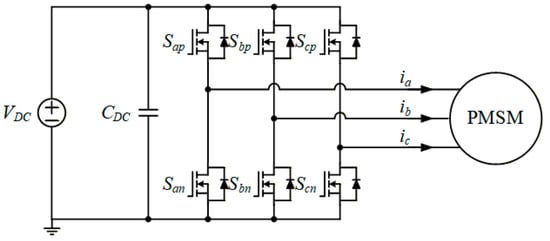
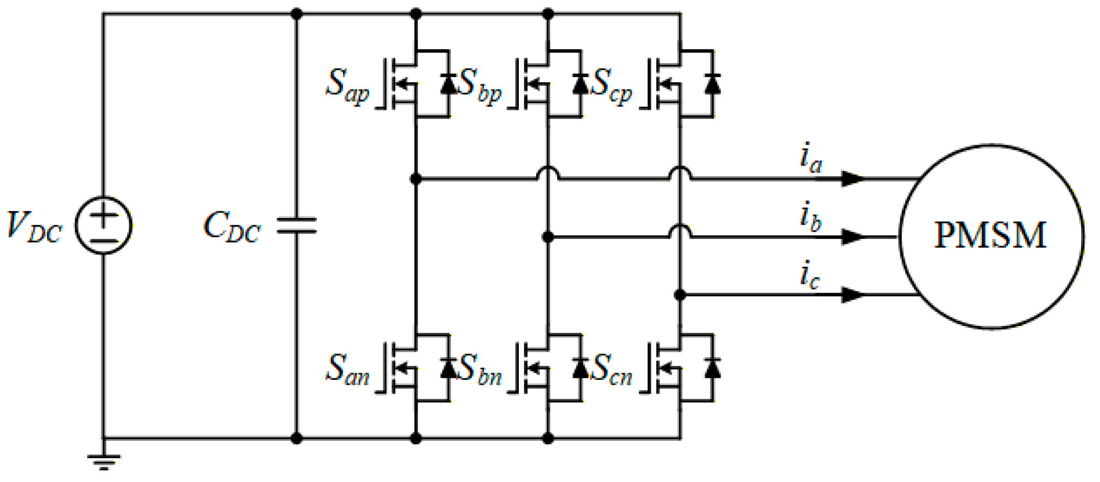
Figure 1 shows the topology of a three-phase PMSM drive inverter. With three in the upper leg and three in the lower leg, the inverter bridge consists of six switching devices. In the process of inversion, six switches are alternately operated using the PWM technique to generate eight switching combinations. Through this process, the DC power is converted into three-phase AC power, which is then used to drive the PMSM.
Figure 1.
Topology of a three-phase PMSM drive inverter.
The PMSM drive is a multivariable and nonlinear system. To simplify the analysis, this paper assumes that the stator has symmetrical three-phase windings and the rotor has a permanent magnet structure. The magnetic circuit is assumed to be unsaturated, the air gap magnetic field is sinusoidal, and the effects of hysteresis and eddy current losses are neglected. The d-axis is aligned with the excitation axis of the permanent magnet, and the q-axis follows the rotor rotation and leads the d-axis by an electrical angle of π/2. The mathematical model of the PMSM in the d–q reference frame can be expressed as shown in (1):
where ud, id, and Ld are the stator voltage, current and inductance on the d-axis, and uq, iq, and Lq are the stator voltage, current and inductance on the q-axis. R, ωe and ψf represent the stator resistance, electrical angular velocity, and permanent magnet flux.
The electromagnetic torque equation of the PMSM can be expressed as shown in (2):
where Te and np represent the electromagnetic torque and the number of pole pairs.
The motion equation of the PMSM can be expressed as shown in (3):
where ωm, J, TL and B represent the mechanical angular velocity, the moment of inertia, the load torque and the damping coefficient.
The relationship between the electrical and mechanical angular velocities can be expressed as in (4):
3. Sliding Mode Control
In general, PI control is used in PMSM drive systems because of its simple implementation. However, PI control is vulnerable to parameter variations and external disturbances, which can degrade the control performance. Because of these limitations of PI control, the SMC method has been used as an alternative. The SMC method has a simple implementation, can be applied to both linear and nonlinear systems, and provides fast responsiveness and high robustness against parameter variations and disturbances.
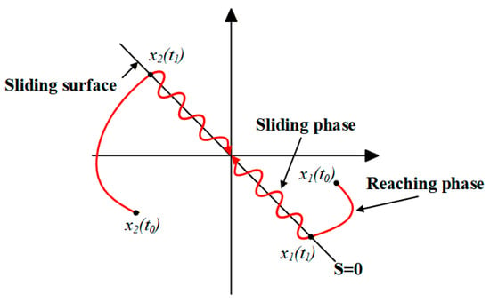
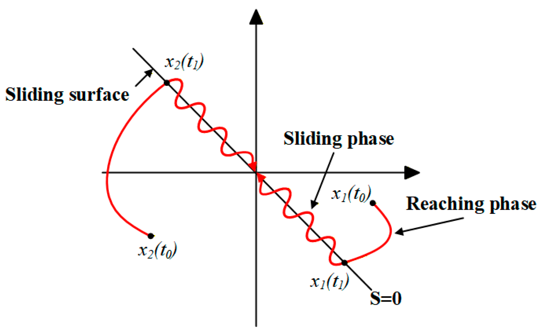
Figure 2 shows the sliding mode mechanism in the phase plane. In the SMC method, a sliding surface is designed based on the difference between the measured value and the reference value, and the control input is constructed so that the system state moves toward this surface. The sliding surface defines the closed-loop dynamics of the system, such as the response speed and damping characteristics. The operation of the SMC method is divided into the reaching phase and the sliding phase. In the reaching phase, the state moves from the initial point x1(t0), x2(t0) to the point x1(t1), x2(t1) on the designed sliding surface. During the reaching phase, the system state is not yet on the sliding surface, and thus, it is not robust against disturbances. Once the state variables reach the sliding phase, the system transitions into the sliding surface. In this phase, the state trajectories move toward the origin along the sliding surface so that the tracking error converges to zero. During the sliding phase, the influence of matched uncertainties and disturbances on the state variables is reduced, and the desired dynamic performance is achieved according to the design of the sliding surface.
Figure 2.
Sliding mode mechanism in phase plane.
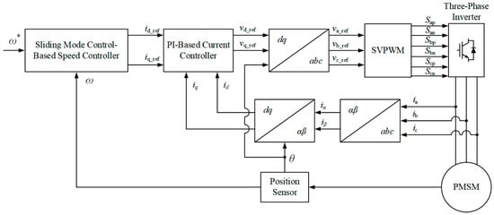
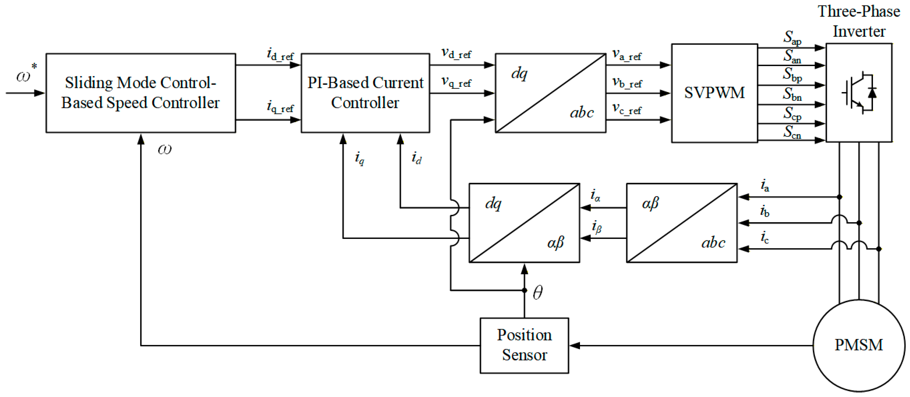
Figure 3 shows the block diagram of the SMC-based PMSM speed control system. The speed error is generated by comparing the reference speed (ω*) with the measured speed (ω). This error is converted into a current reference through the proposed SMC-based speed controller. The current reference is processed by the PI-based current controller to produce a voltage reference, and the switching signals for the three-phase inverter are generated through the coordinate transformation using the estimated electrical rotor angle and SVPWM.
Figure 3.
Block diagram of the SMC-based PMSM speed control system.
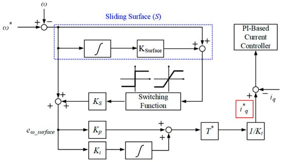
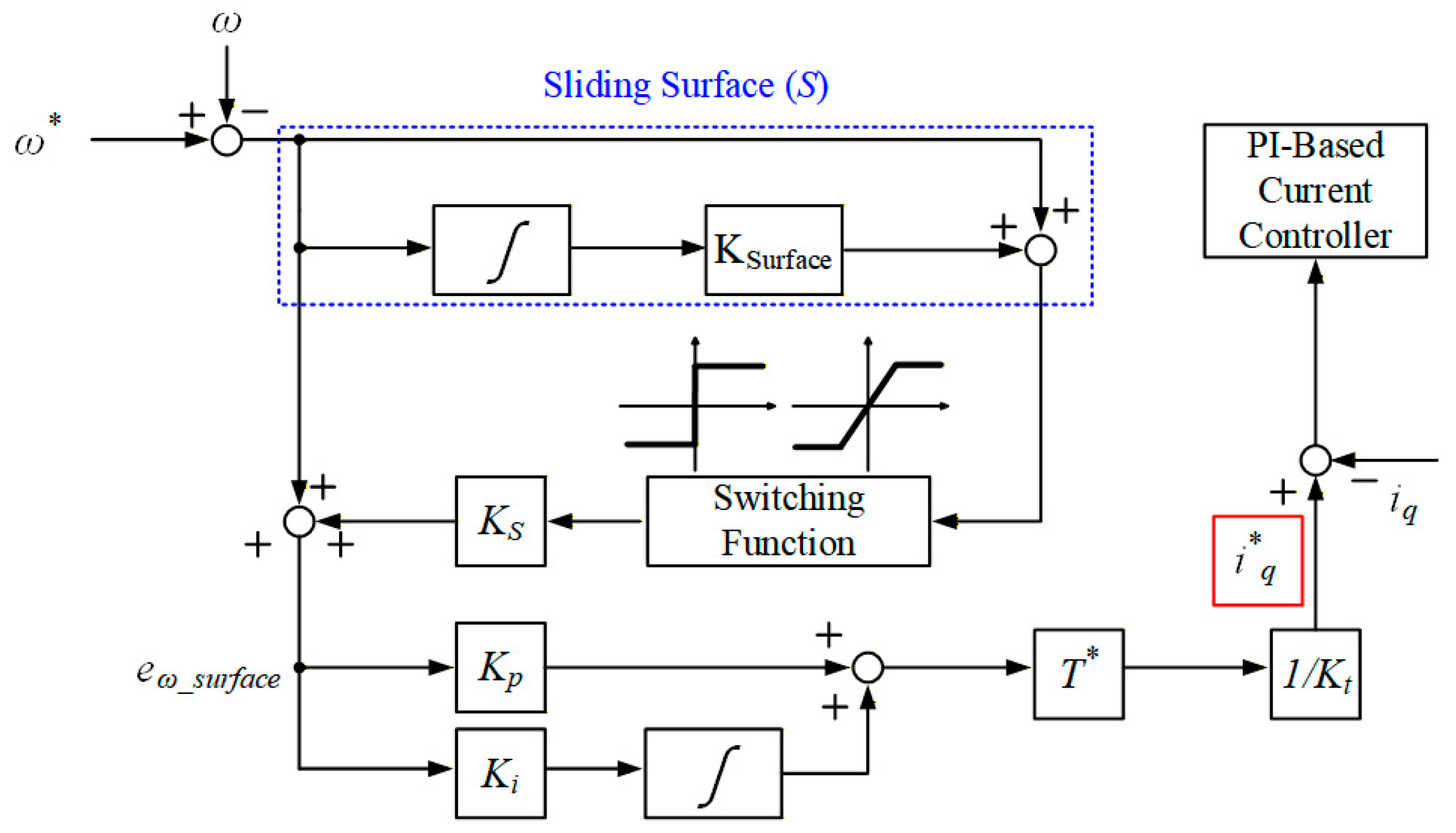
Figure 4 shows the control block diagram of the proposed SMC method. The state variable of the system is defined as the speed error, which can be expressed as in (5):
Figure 4.
Control block diagram of the proposed SMC method.
Based on the conventional linear surface, an integral term of the speed error is included in the sliding to eliminate the steady-state error. The integral sliding surface can be expressed as in (6):
where c is the sliding coefficient. The sliding coefficient determines the slope of the surface, which affects how the error converges to the sliding surface. In addition, the sliding coefficient must be positive to ensure the stability of the sliding operation.
To ensure that the state reaches and remains on this sliding surface, a switching function is employed in the SMC method. In the conventional SMC method, the signum function is used as the switching function, which can be expressed in (7):
The signum function provides fast responsiveness and strong robustness to matched uncertainties by generating a large control input whenever the state deviates from the sliding surface. Using the signum function, a new error variable based on the SMC method can be expressed as in (8):
where Ks represents the gain of the SMC method. Increasing Ks improves the system responsiveness, but it may also cause chattering in the steady state, which can damage the controller. Therefore, proper adjustment of Ks is required.
By setting eω_surface as the input to the PI controller, the torque reference (T*) generated by the PI controller can be expressed as in (9):
where Kp and Ki represent the proportional and integral gains of the PI controller.
Finally, the generated T* is converted into the q-axis current reference (iq*) using the torque constant (Kt). iq* can be expressed as in (10):
Additionally, the error between iq* and the measured q-axis current (iq) is used as the input of the PI-based current controller.
4. Various Switching Functions
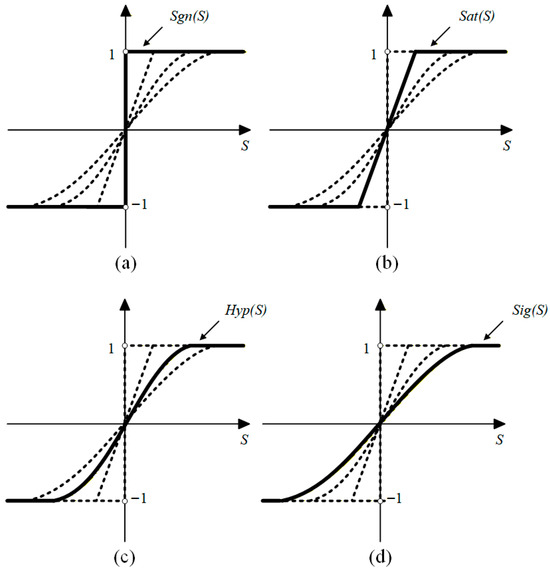
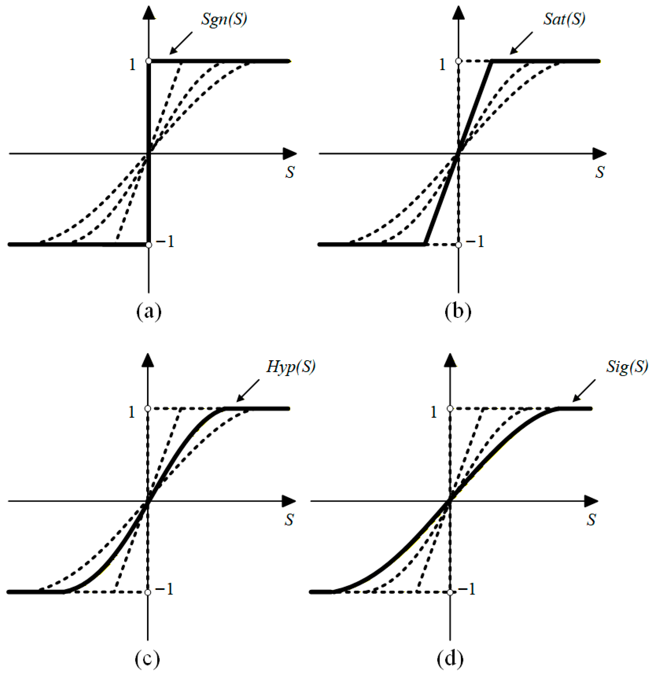
Figure 5 shows various switching functions. In the SMC method, after the state variable reaches the sliding surface, the switching function keeps the state variable on the surface while the state variable moves toward the origin. The shape of the switching function affects the speed when approaching sliding surface, the magnitude of chattering, and the overall stability and robustness of the PMSM drive system. Therefore, the proper selection of the switching function is important.
Figure 5.
Various switching functions: (a) signum function; (b) saturation function; (c) hyperbolic function; (d) sigmoid function.
Figure 5a shows the shape of a signum function. In traditional SMC methods, the signum function is used for the switching function. The signum function has a simple structure and is easy to implement. However, due to its discontinuous switching characteristic, the output of the signum function changes instantaneously to −1, 0, or 1 near S = 0, which can induce chattering in steady-state operation.
4.1. Saturation Function
Figure 5b shows the shape of a saturation function. The saturation function is defined as in (11):
where α is the saturation coefficient. The saturation function sets a boundary layer around the sliding surface, and within this region, the control input changes linearly. This maintains control characteristics similar to the signum function while reducing discontinuous switching and effectively reducing chattering. When the value of α that determines the boundary layer thickness increases, chattering decreases but the steady-state error increases. Conversely, when α becomes smaller, the steady-state error decreases while chattering increases.
4.2. Hyperbolic Function
Figure 5c shows the shape of a hyperbolic function. The hyperbolic function is defined as in (12):
where β is the hyperbolic coefficient. The hyperbolic function is a continuous switching function that allows the control input to vary smoothly near the sliding surface. Unlike the saturation function, which explicitly defines a boundary layer around the sliding surface, the hyperbolic function exhibits a gradual variation in the control input near the sliding surface due to its exponential characteristics. The value of β in the hyperbolic function determines the slope of the control input near the sliding surface. When the value of β increases, the control input changes more sharply near the sliding surface, resulting in a reduced steady-state error but increased chattering. Conversely, when the value of β decreases, the control input varies more smoothly, leading to reduced chattering while the steady-state error increases. Additionally, due to the involvement of exponential operations, the computational burden increases compared with the saturation and signum functions.
4.3. Sigmoid Function
Figure 5d shows the shape of a sigmoid function. The sigmoid function is defined as in (13):
where γ is the sigmoid coefficient. The sigmoid function is a continuous switching function. The sigmoid function is similar to the hyperbolic function. However, it has a smoother slope near the sliding surface. The sigmoid function becomes similar to the hyperbolic function when γ = 2β. The value of γ in the sigmoid function determines the slope of the control input near the sliding surface. When the value of γ increases, the control input changes more sharply near the sliding surface, resulting in a reduced steady-state error but increased chattering. Conversely, when the value of γ decreases, the control input varies more smoothly, leading to reduced chattering while the steady-state error increases. Additionally, due to the involvement of exponential operations, the computational burden increases compared with the saturation and signum functions.
As a result, the use of the signum function in the SMC method causes chattering due to discontinuous switching. This chattering increases mechanical vibrations and noise during the PMSM drive, which can degrade the system stability and lifetime. Such chattering can be reduced by employing various switching functions, such as the hyperbolic, sigmoid, and saturation functions.
5. Simulation Results
To validate the chattering reduction using various switching functions in the SMC method for PMSM drives, simulations were conducted. The parameters used in the simulations are shown in Table 1.
Table 1.
Simulation parameters.
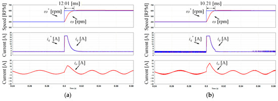
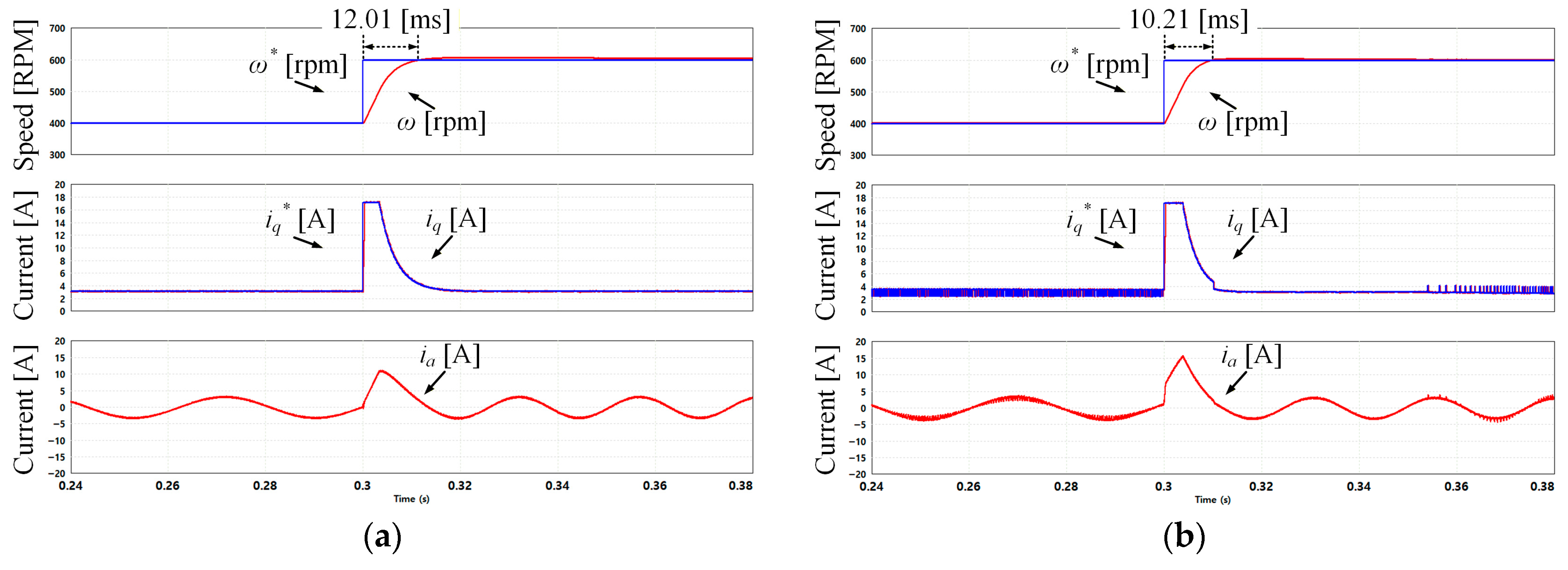
Figure 6 presents the simulation results of the transient-state response of the PMSM under a 5 Nm load. The results present a comparison between the PI controller and the SMC method using the signum function. The ω* was changed from 400 rpm to 600 rpm at 0.3 s. Figure 6a presents the simulation results of the PI controller, where ω reaches ω* in 12.01 ms. Figure 6b presents the simulation results of the SMC method using the signum function, where ω reaches ω* in 10.21 ms. Compared with the PI controller, the SMC method using the signum function improves the responsiveness by approximately 14.99%. However, in a steady state, the SMC method using the signum function exhibits chattering in iq and iq*.
Figure 6.
Simulation results of the transient-state response of the PMSM under a 5 Nm load: (a) PI controller; (b) SMC method using the signum function.
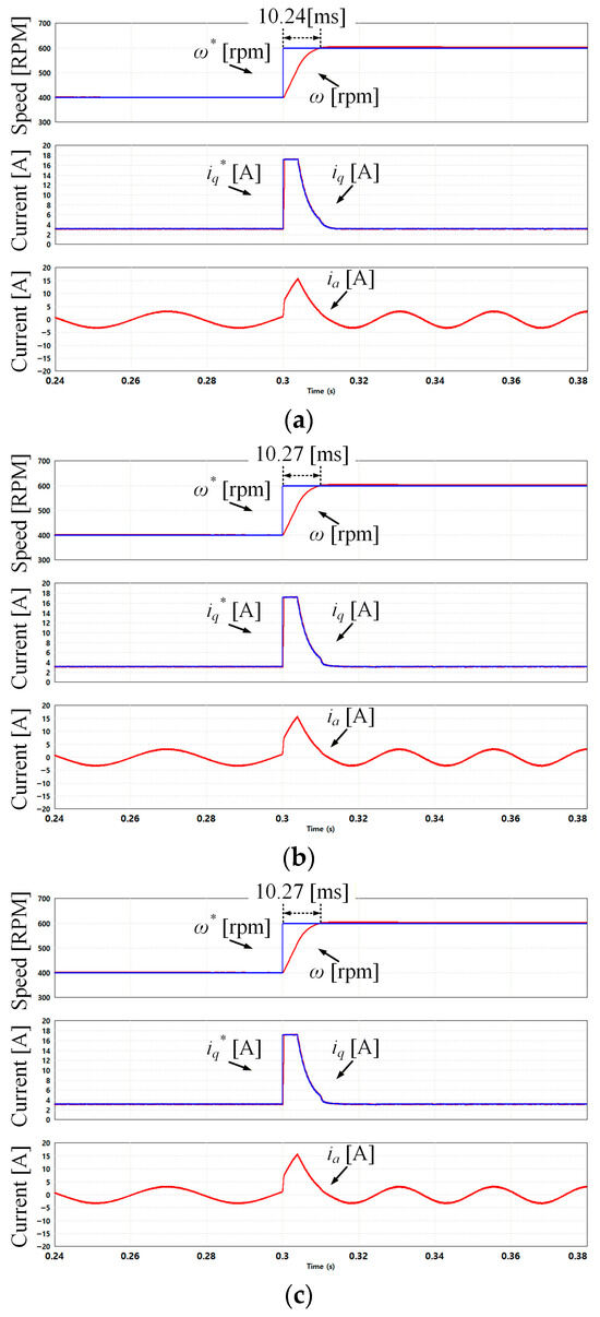
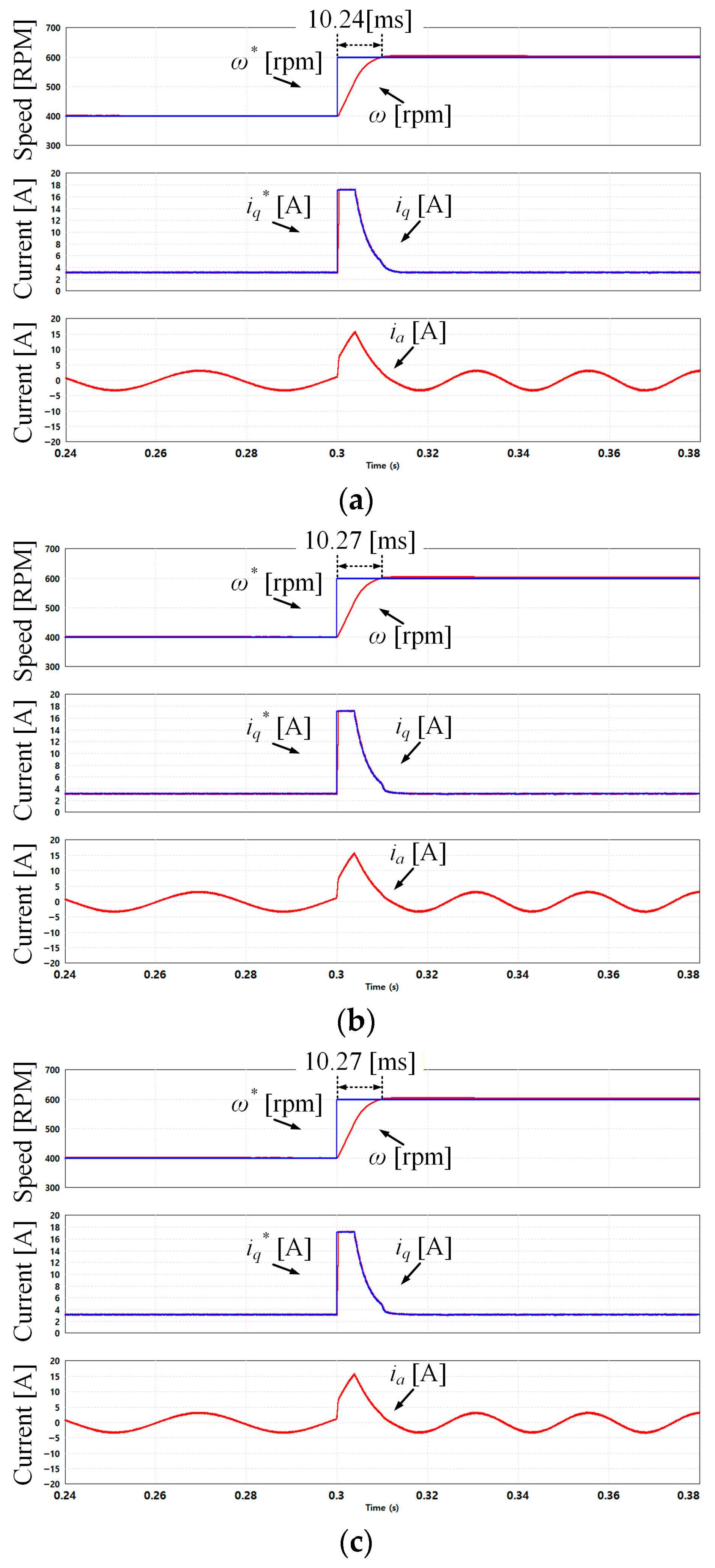
Figure 7 presents the simulation results of the transient-state response of the PMSM under a 5 Nm load. The results present a comparison between the various switching functions when using the SMC method. Similarly, the ω* was changed from 400 rpm to 600 rpm at 0.3 s. The coefficients α, β, and γ in the saturation, hyperbolic, and sigmoid switching functions determine the switching characteristics and affect the control accuracy and responsiveness. For the saturation switching function, the coefficient α determines the width of the boundary layer. A larger α results in a wider boundary layer, which reduces chattering while increasing the steady-state error and decreasing responsiveness. Conversely, a smaller α improves the responsiveness and tracking accuracy, with the chattering becoming more pronounced. For the hyperbolic switching function, the coefficient β determines the slope of the switching function. A larger β results in a steeper slope, which improves the responsiveness and tracking accuracy and may increase the oscillatory behavior. Conversely, a smaller β provides smoother control behavior with reduced oscillations, while the responsiveness decreases. For the sigmoid switching function, the coefficient γ determines the slope of the switching function. A larger γ results in a steeper slope, which improves the responsiveness and steady-state accuracy. Conversely, a smaller γ provides smoother control behavior with reduced chattering, while the responsiveness decreases. In this paper, the switching function coefficients were selected through experimental tuning to reduce chattering. The coefficients were chosen to provide the highest responsiveness without causing chattering. Figure 7a presents simulation results of the SMC method using the saturation function, where the coefficient α was set to 3, and ω reaches ω* in 10.24 ms. Figure 7b presents simulation results of the SMC method using the hyperbolic function, where the coefficient β was set to 1, and ω reaches ω* in 10.27 ms. Figure 7c presents simulation results of the SMC method using the sigmoid function, where the coefficient γ was set to 1, and ω reaches ω* in 10.27 ms. As γ was set to 2β, the results of the two switching functions are nearly the same.
Figure 7.
Simulation results of the transient-state response of the PMSM under a 5 Nm load: (a) SMC method using the saturation function; (b) SMC method using the hyperbolic function; (c) SMC method using the sigmoid function.
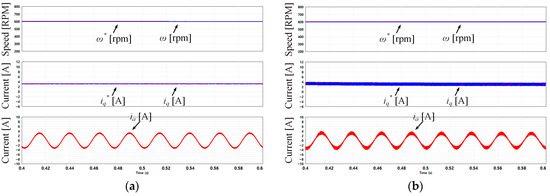
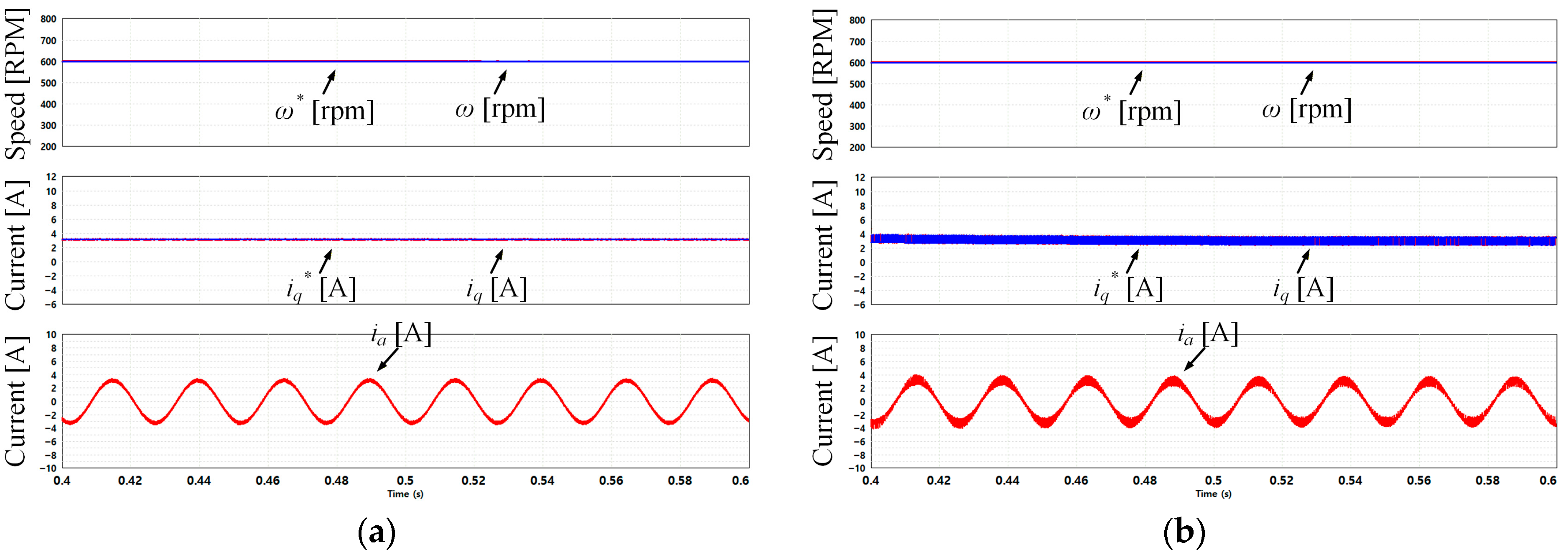
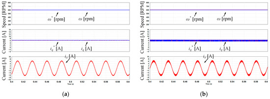
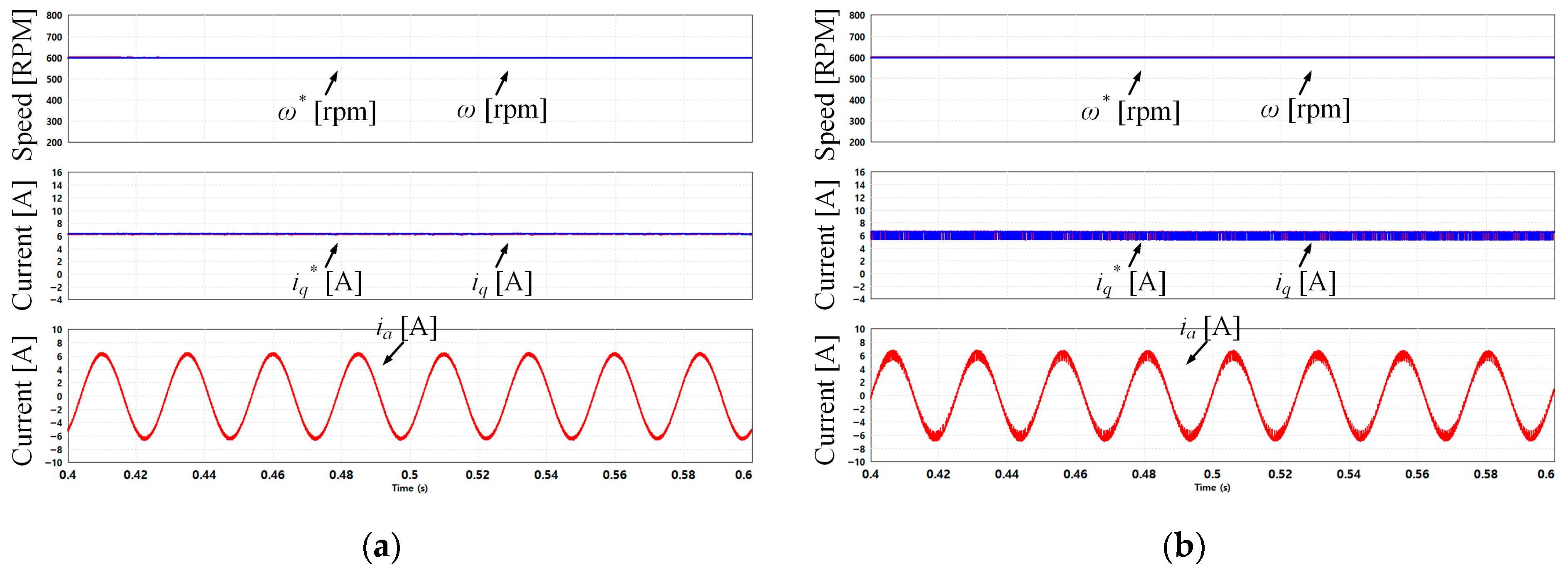
Figure 8 presents the simulation results of the steady-state response of the PMSM under a 5 Nm load for comparison of the chattering behavior in iq* for the (a) PI controller and (b) SMC method using the signum function. Both controllers are controlled normally in the steady state, but the SMC method using the signum function exhibits chattering in iq and iq*.
Figure 8.
Simulation results of the steady-state response of the PMSM under a 5 Nm load for comparison of the chattering behavior in iq*: (a) PI controller; (b) SMC method using the signum function.
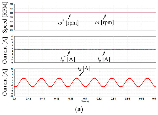
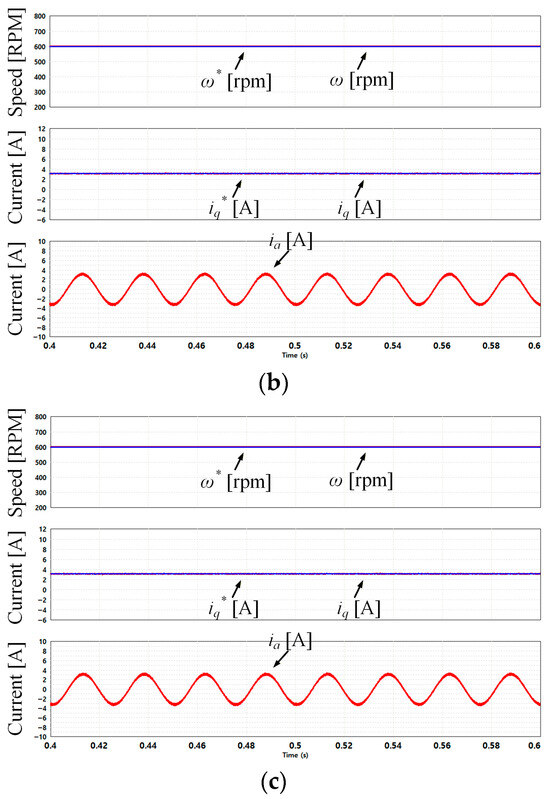
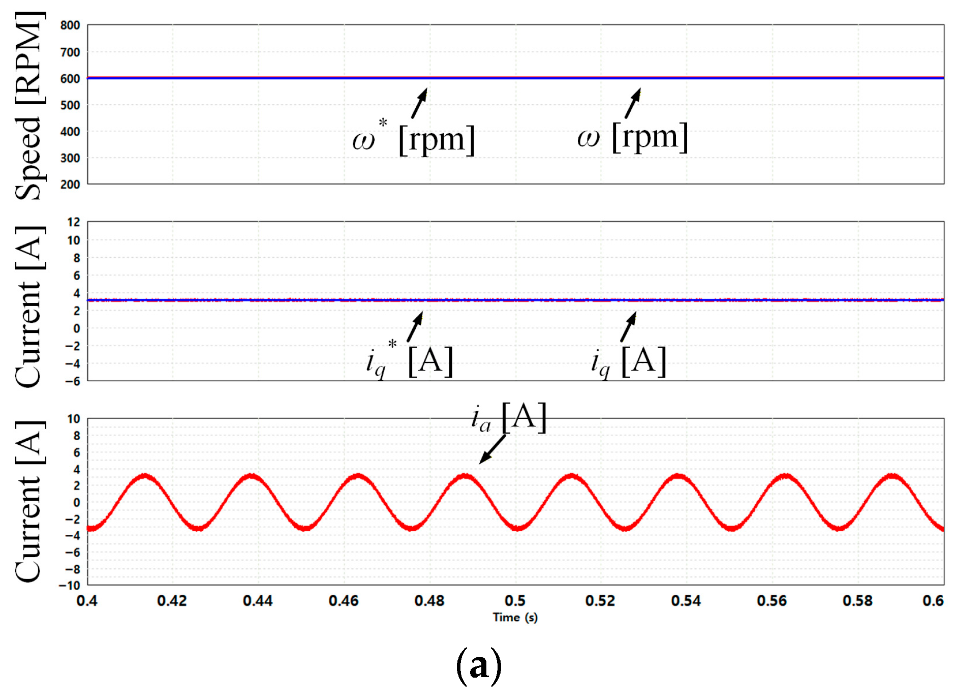
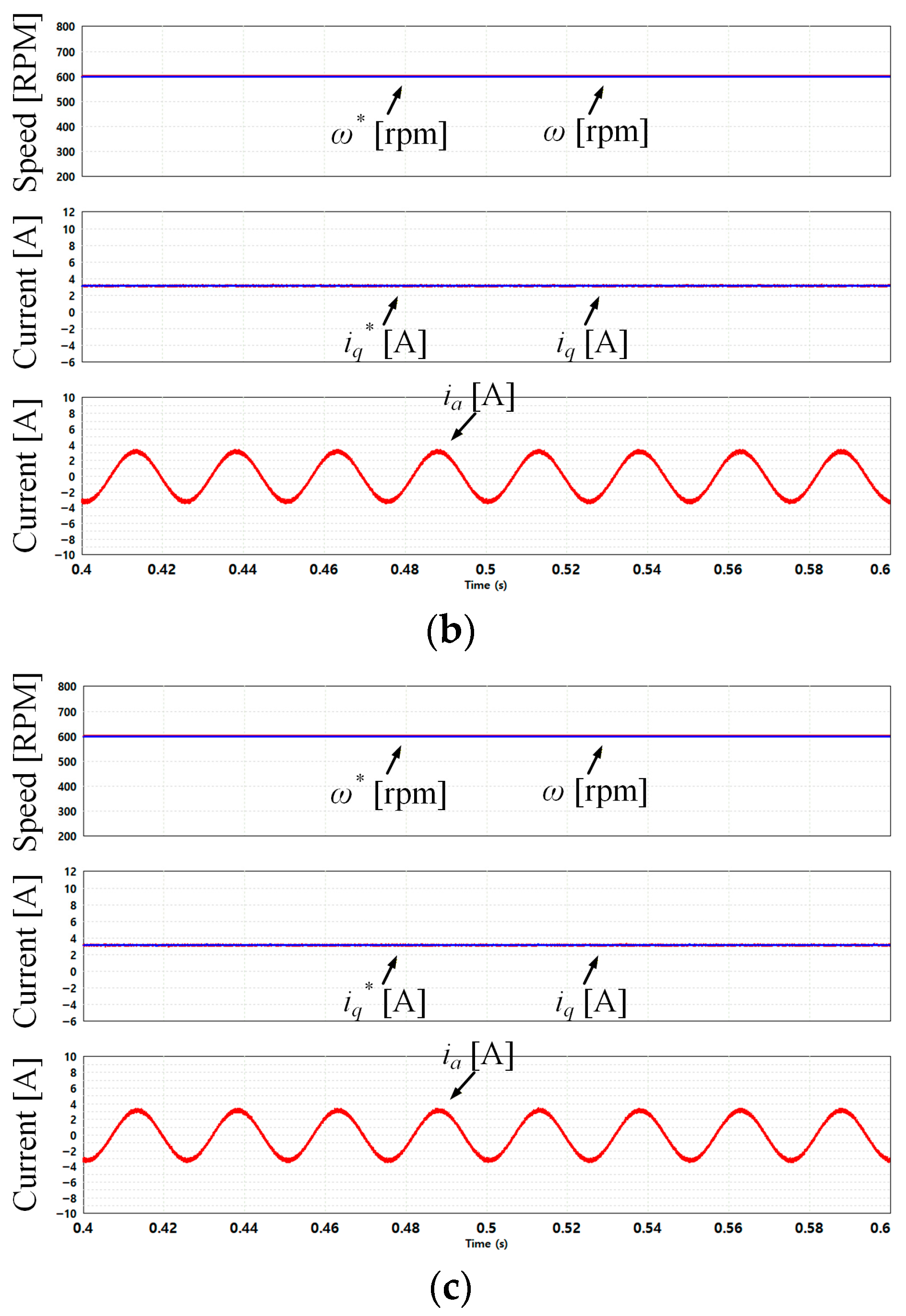
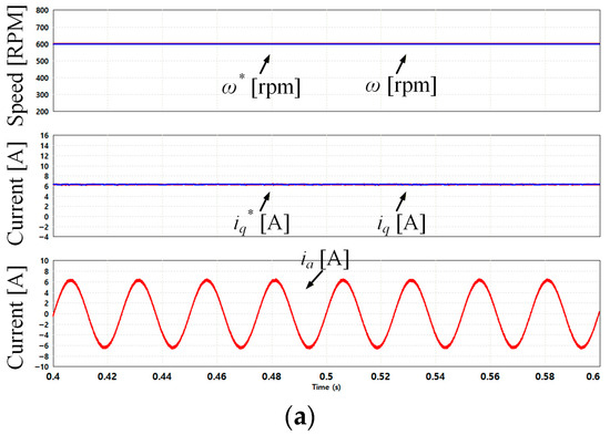
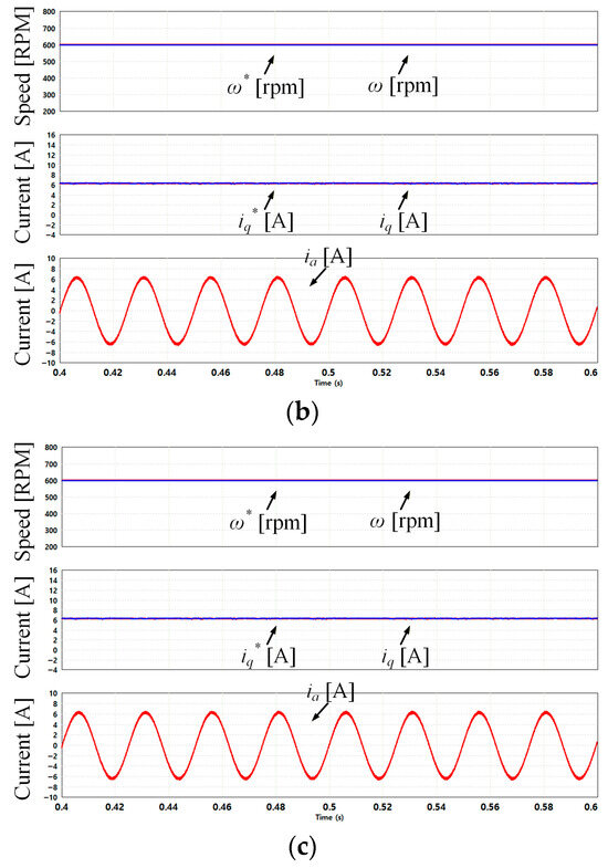
Figure 9 presents the simulation results of the steady-state response of the PMSM under a 5 Nm load for comparison of chattering behavior in iq* for the (a) SMC method using the saturation function, (b) SMC method using the hyperbolic function and (c) SMC method using the sigmoid function. All controllers are controlled normally, and chattering does not occur in iq and iq*. As shown in the simulation results, using the signum function improves the system’s responsiveness compared with PI control, but chattering occurs in iq and iq*. This chattering can increase mechanical vibrations in the system, cause power loss, and degrade overall performance. As a result, using various improved switching functions can mitigate chattering while reducing mechanical vibrations and enhancing the overall performance.
Figure 9.
Simulation results of the steady-state response of the PMSM under a 5 Nm load: (a) SMC method using the saturation function; (b) SMC method using the hyperbolic function; (c) SMC method using the sigmoid function.
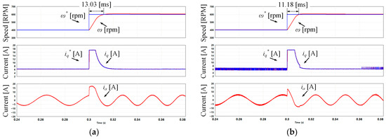
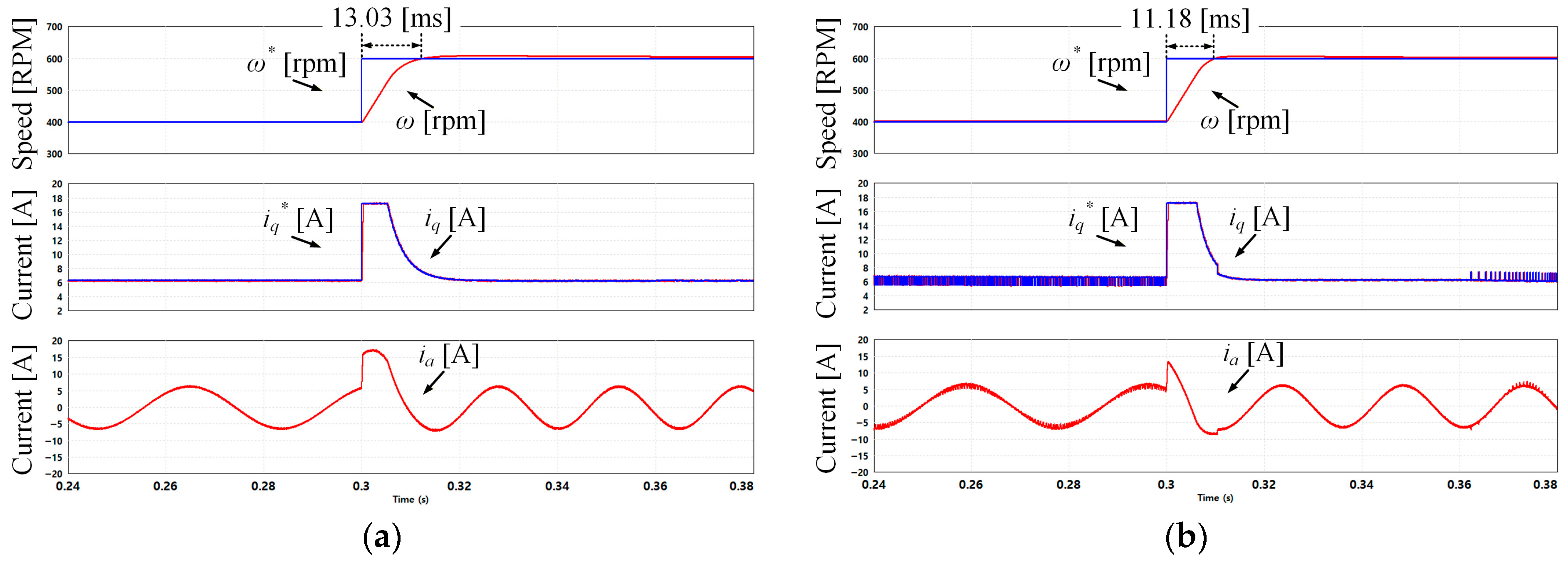
Figure 10 presents the simulation results of the transient-state response of the PMSM under a 10 Nm load. The results present a comparison between the PI controller and the SMC method using the signum function. The ω* was changed from 400 rpm to 600 rpm at 0.3 s. Figure 10a presents the simulation results of the PI controller, where ω reaches ω* in 13.03 ms. Figure 10b presents simulation results of the SMC method using the signum function, where ω reaches ω* in 11.18 ms. Compared with the PI controller, the SMC method using the signum function improves the responsiveness by approximately 15.75%. However, in the steady state, the SMC method using the signum function exhibits chattering in iq and iq*.
Figure 10.
Simulation results of the transient-state response of the PMSM under a 10 Nm load: (a) PI controller; (b) SMC method using the signum function.
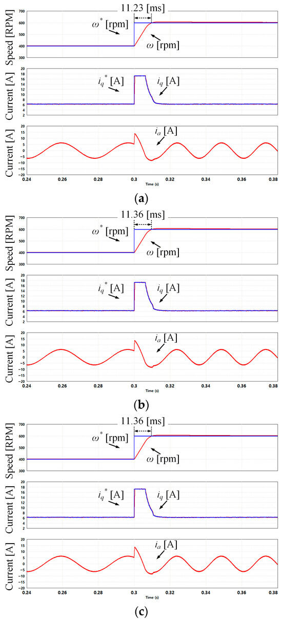
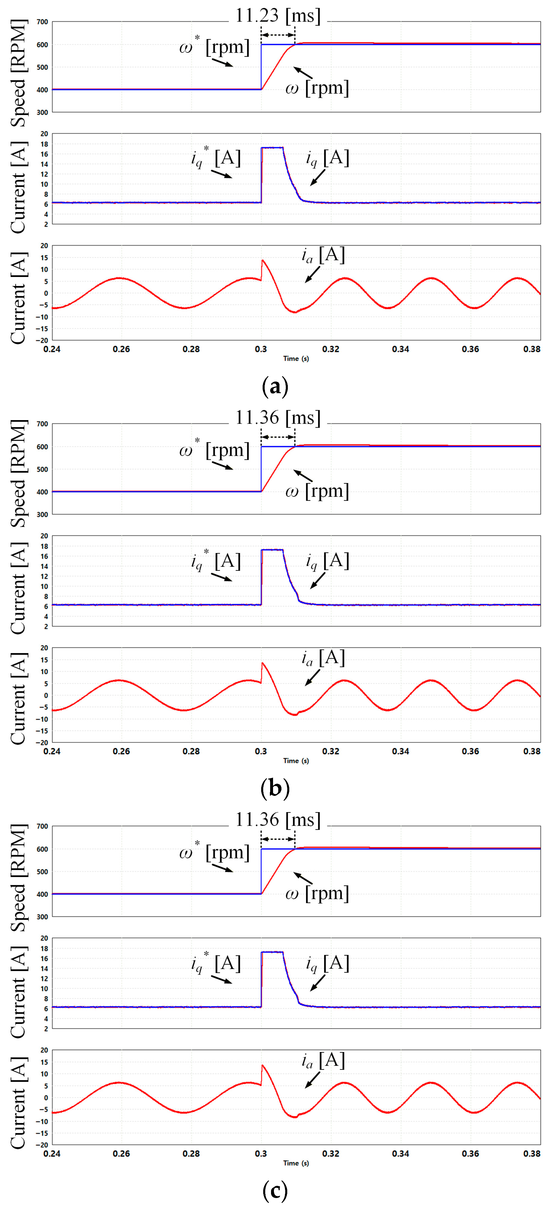
Figure 11 presents the simulation results of the transient-state response of the PMSM under a 10 Nm load. The results present a comparison between the various switching functions when using the SMC method. Similarly, the ω* was changed from 400 rpm to 600 rpm at 0.3 s. Figure 11a presents simulation results of the SMC method using the saturation function, where the coefficient α was set to 3, and ω reaches ω* in 11.23 ms. Figure 11b presents simulation results of the SMC method using the hyperbolic function, where the coefficient β was set to 1, and ω reaches ω* in 11.36 ms. Figure 11c presents simulation results of the SMC method using the sigmoid function, where the coefficient γ was set to 1, and ω reaches ω* in 11.36 ms. As γ was set to 2β, the results of the two switching functions are nearly the same.
Figure 11.
Simulation results of the transient-state response of the PMSM under a 10 Nm load: (a) SMC method using the saturation function; (b) SMC method using the hyperbolic function; (c) SMC method using the sigmoid function.
Figure 12 presents the simulation results of the steady-state response of the PMSM under a 10 Nm load for comparison of chattering behavior in iq* for the (a) PI controller and (b) SMC method using the signum function. Both controllers are controlled normally in the steady state, but the SMC method using the signum function exhibits chattering in iq and iq*.
Figure 12.
Simulation results of the steady-state response of the PMSM under a 10 Nm load for comparison of chattering behavior in iq*: (a) PI controller; (b) SMC method using the signum function.
Figure 13 presents the simulation results of the steady-state response of the PMSM under a 10 Nm load for comparison of chattering behavior in iq* for the (a) SMC method using the saturation function, (b) SMC method using the hyperbolic function and (c) SMC method using the sigmoid function. Similar to the 5 Nm case, chattering is not observed in iq and iq* for all switching functions, showing the same chattering suppression under a higher load condition. Additionally, Table 2 presents the simulation performance comparison under a 10 Nm load.
Figure 13.
Simulation results of the steady-state response of the PMSM under a 10 Nm load for comparison of the chattering behavior in iq*: (a) SMC method using the saturation function; (b) SMC method using the hyperbolic function; (c) SMC method using the sigmoid function.
Table 2.
Simulation performance comparison under a 10 Nm load.
6. Experiment Results
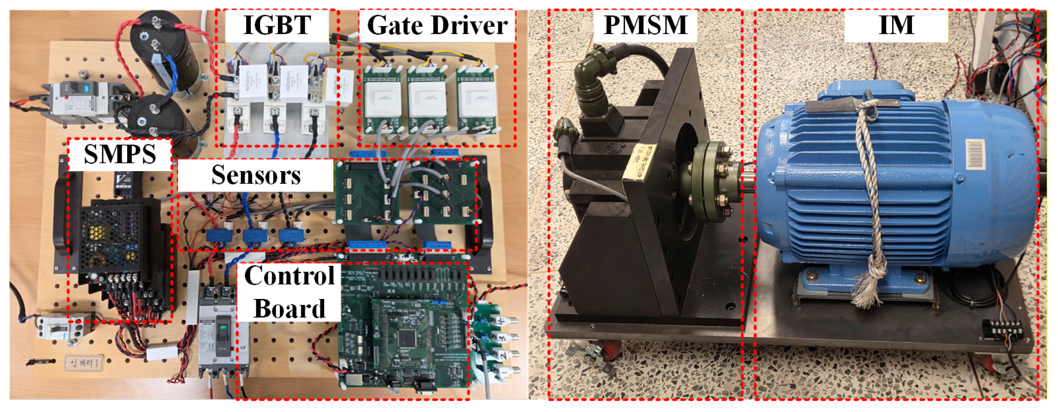
Figure 14 presents the experimental setup that consisted of an inverter and a motor–generator set. The inverter consisted of an SMPS, IGBTs, gate drivers, sensors, and a control board. The PMSM parameters used in the experiment were the same as those in Table 1. Due to the risk of chattering caused by the signum function, the speed control bandwidth was reduced during the experiment.
Figure 14.
Experimental setup.
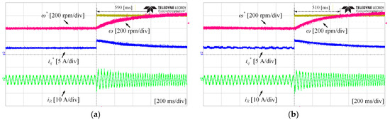
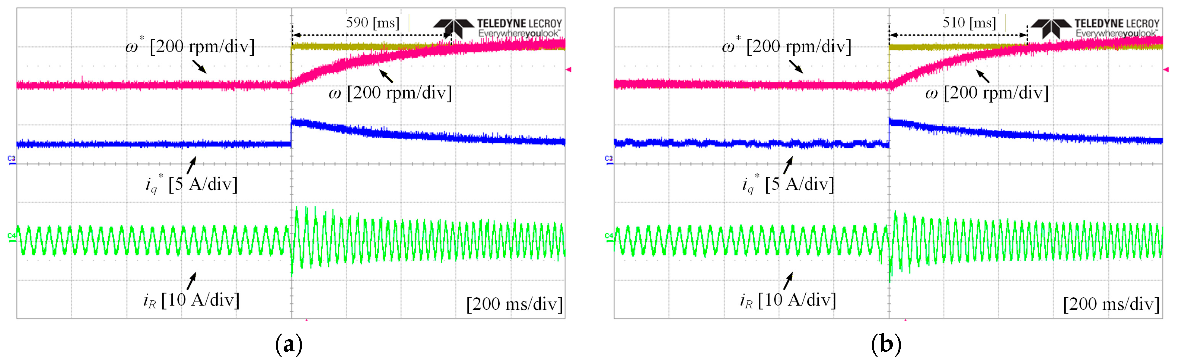
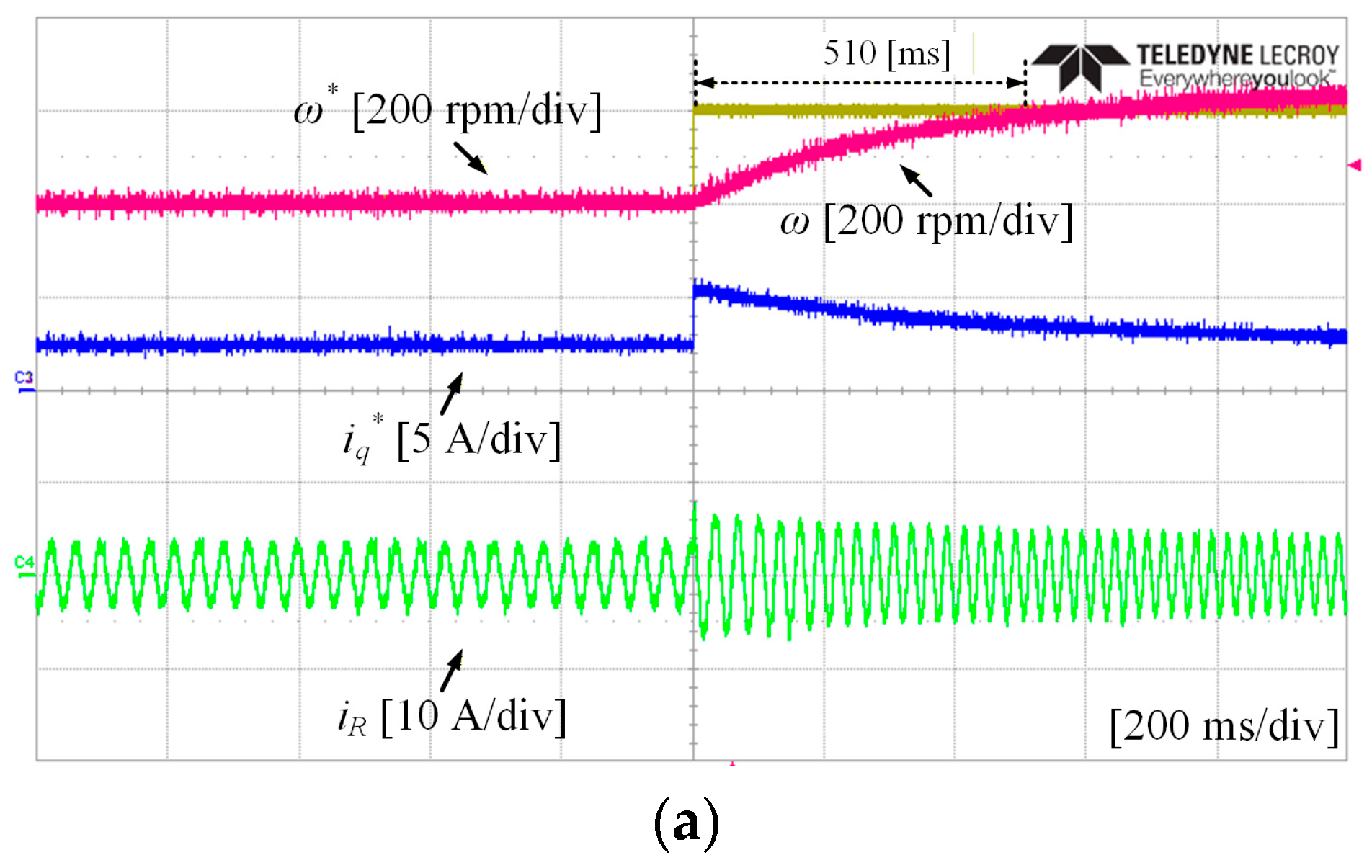
Figure 15 presents the experimental results of the transient-state response of the PMSM under a 5 Nm load. The results present a comparison between the PI controller and the SMC method using the signum function. The ω* was changed from 400 rpm to 600 rpm. Figure 15a presents the experimental results of the PI controller, where ω reaches ω* in 590 ms. Figure 15b presents the experimental results of the SMC method using the signum function, where ω reaches ω* in 510 ms. Compared with the PI controller, the SMC method using the signum function improves the responsiveness by approximately 13.56%. However, in the steady state, the SMC method using the signum function exhibits chattering in iq*.
Figure 15.
Experimental results of the transient-state response of the PMSM under a 5 Nm load: (a) PI controller; (b) SMC method using the signum function.
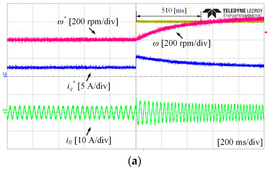
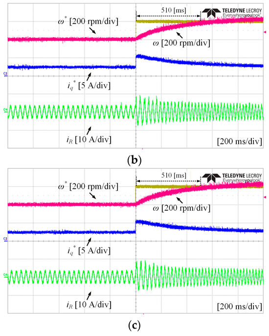
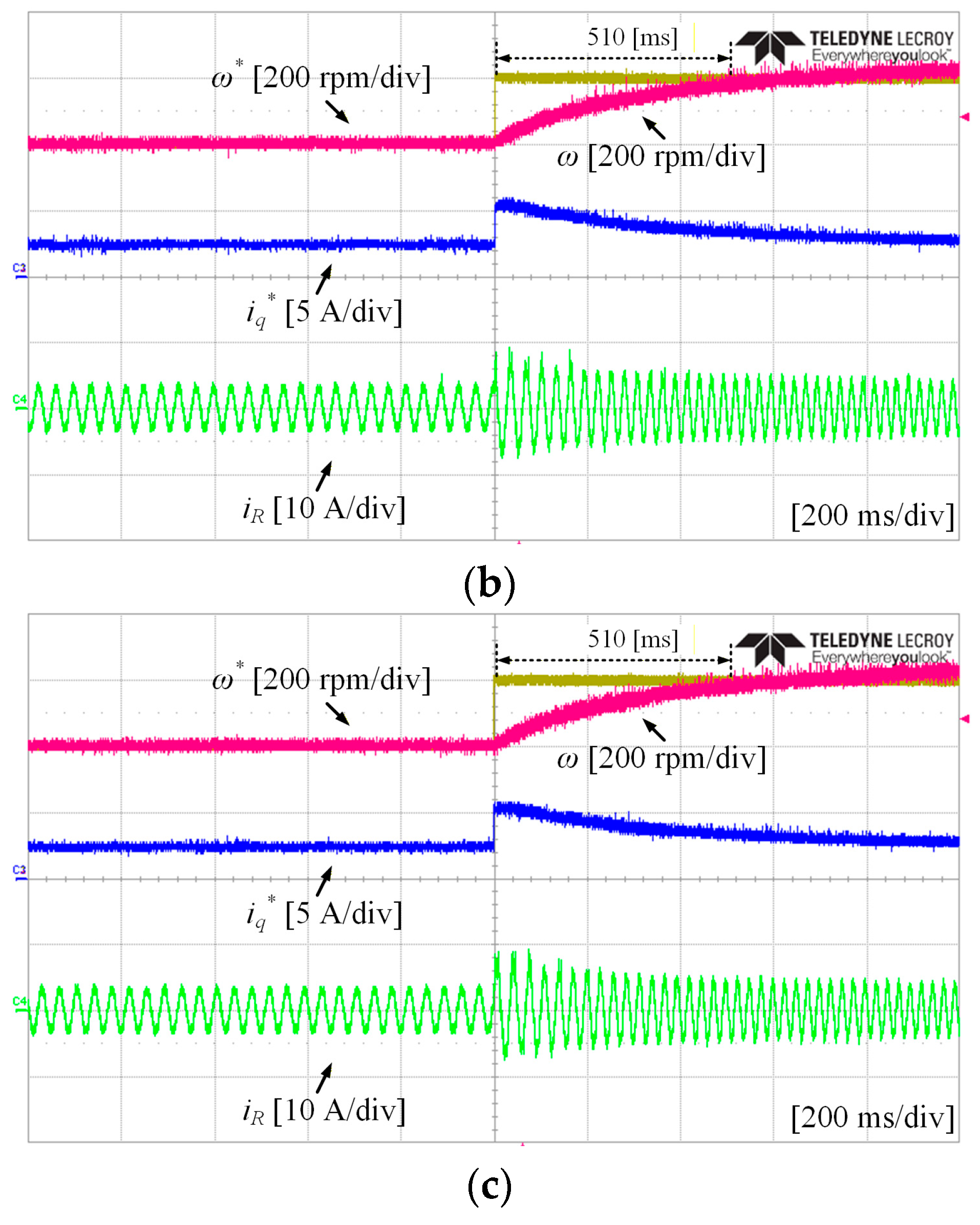
Figure 16 presents the experimental results of the transient-state response of the PMSM under a 5 Nm load. The results present a comparison between the various switching functions when using the SMC method. Similarly, the ω* was changed from 400 rpm to 600 rpm. The coefficients were chosen to provide the highest responsiveness without causing chattering. Figure 16a presents the experimental results of the SMC method using the saturation function, where the coefficient α was set to 3, and ω reaches ω* in 510 ms. Figure 16b presents the experimental results of the SMC method using the hyperbolic function, where the coefficient β was set to 1, and ω reaches ω* in 510 ms. Figure 16c presents the experimental results of the SMC method using the sigmoid function, where the coefficient γ was set to 1, and ω reaches ω* in 510 ms. The results of all switching functions were similar because the optimal coefficients were determined for each case.
Figure 16.
Experimental results of the transient-state response of the PMSM under a 5 Nm load: (a) SMC method using the saturation function; (b) SMC method using the hyperbolic function; (c) SMC method using the sigmoid function.
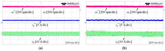
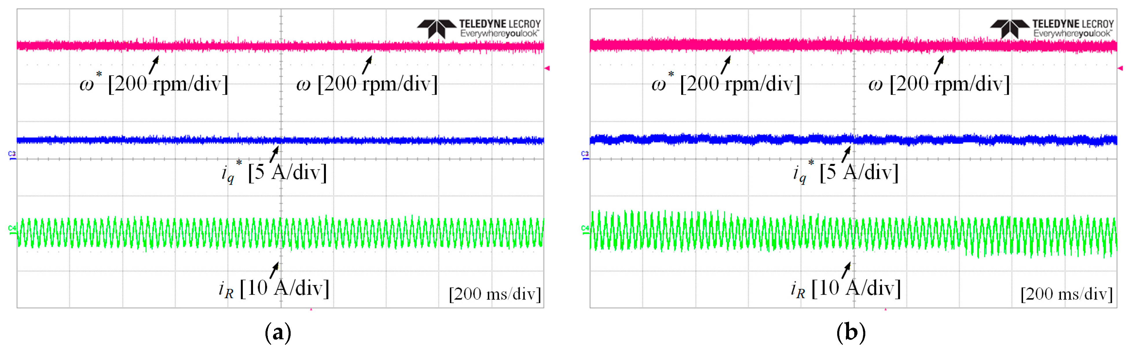
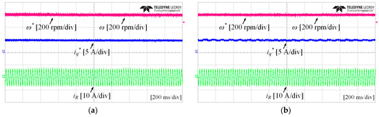
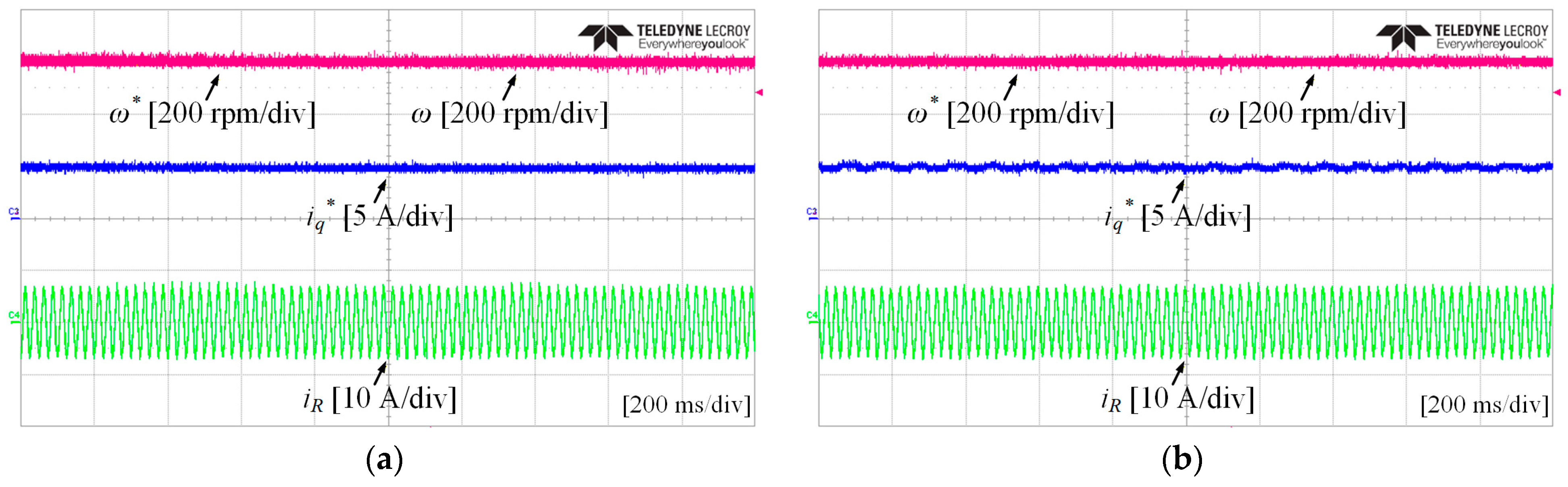
Figure 17 presents the experimental results of the steady-state response of the PMSM under a 5 Nm load for comparison of chattering behavior in iq* for the (a) PI controller and (b) SMC method using the signum function. Both controllers are controlled normally in the steady state, but the SMC method using the signum function exhibits chattering in iq*.
Figure 17.
Experimental results of the steady-state response of the PMSM under a 5 Nm load for comparison of the chattering behavior in iq*: (a) PI controller; (b) SMC method using the signum function.
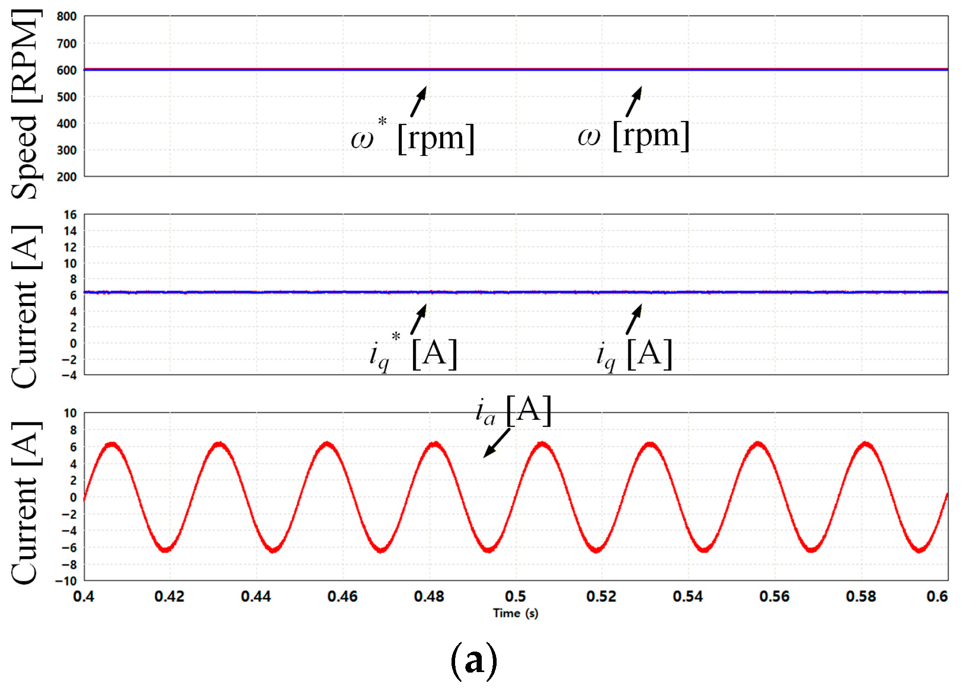
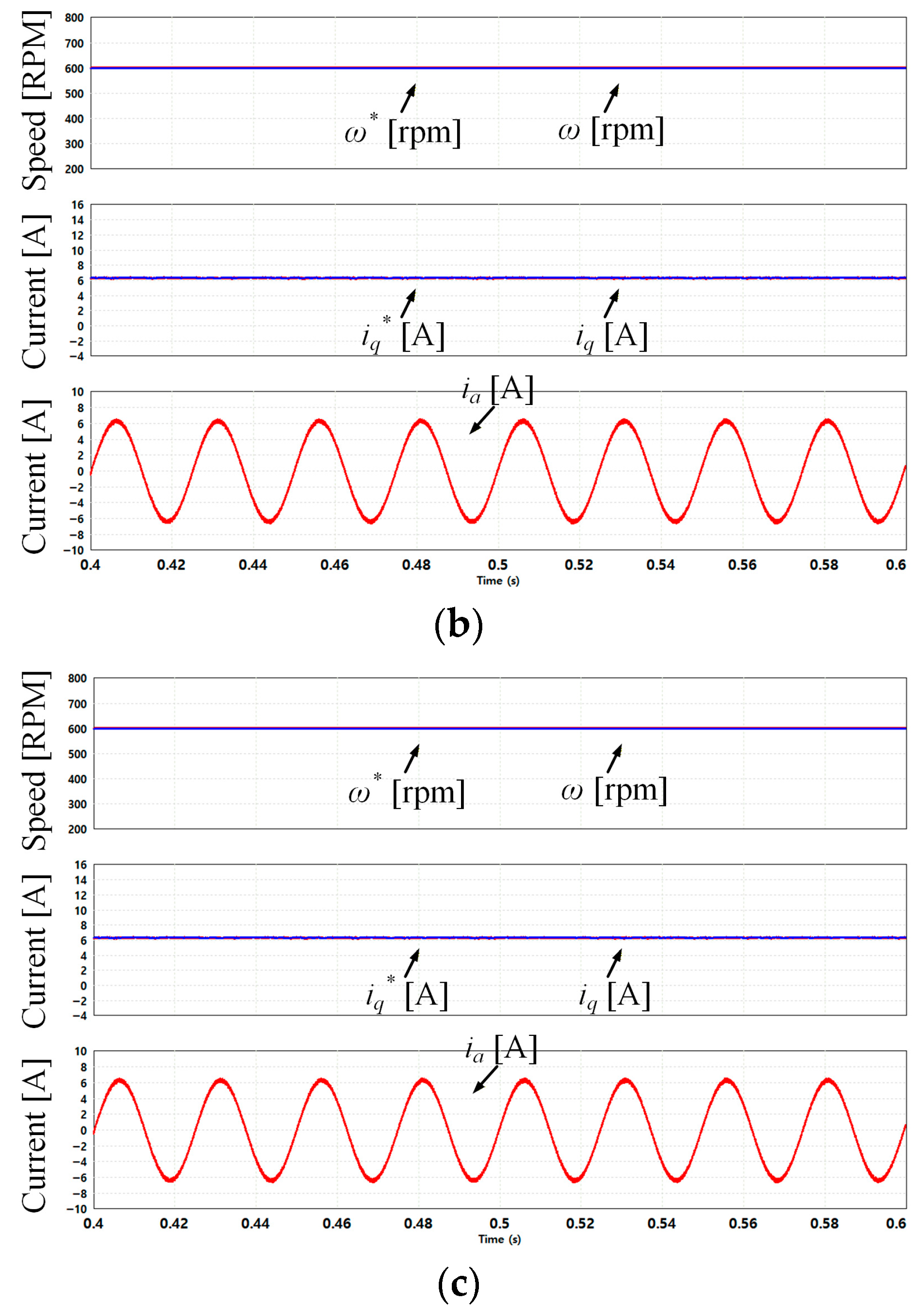
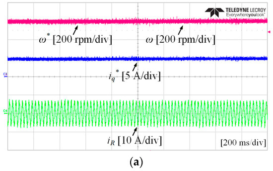
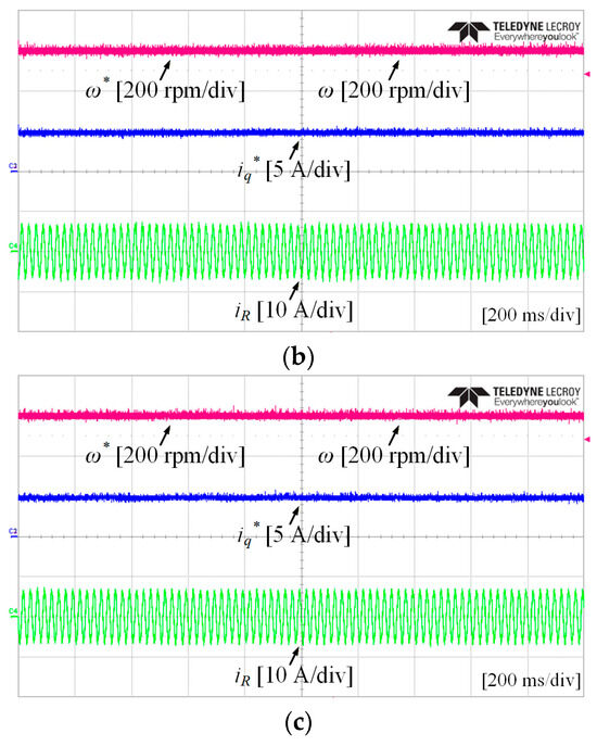
Figure 18 presents the experimental results of the steady-state response of the PMSM under a 5 Nm load for comparison of the chattering behavior in iq* for the (a) SMC method using the saturation function, (b) SMC method using the hyperbolic function and (c) SMC method using the sigmoid function. All controllers are controlled normally, and chattering does not occur in iq*. As shown in the experimental results, using the signum function improves the systems responsiveness compared with PI control, but chattering occurs in iq*. This chattering can increase mechanical vibrations in the system, cause power loss, and degrade overall performance. As a result, using various improved switching functions can mitigate chattering while reducing mechanical vibrations and enhancing the overall performance.
Figure 18.
Experimental results of the steady-state response of the PMSM under a 5 Nm load for comparison of the chattering behavior in iq*: (a) SMC method using the saturation function; (b) SMC method using the hyperbolic function; (c) SMC method using the sigmoid function.
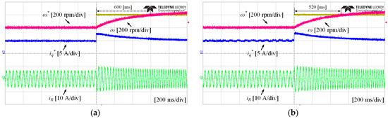
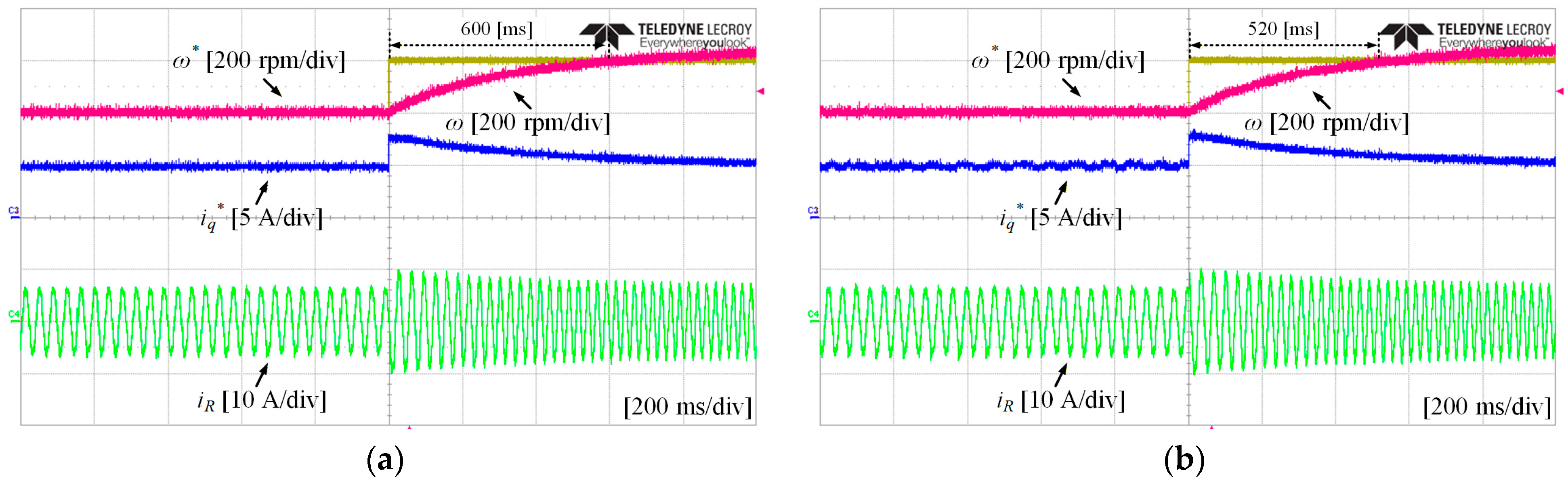
Figure 19 presents the experimental results of the transient-state response of the PMSM under a 10 Nm load. The results present a comparison between the PI controller and the SMC method using the signum function. The ω* was changed from 400 rpm to 600 rpm. Figure 19a presents experimental results of the PI controller, where ω reaches ω* in 600 ms. Figure 19b presents experimental results of the SMC method using the signum function, where ω reaches ω* in 520 ms. Compared with the PI controller, the SMC method using the signum function improves responsiveness by approximately 13.33%. However, in the steady state, the SMC method using the signum function exhibits chattering in iq*.
Figure 19.
Experimental results of the transient-state response of the PMSM under a 10 Nm load: (a) PI controller; (b) SMC method using the signum function.
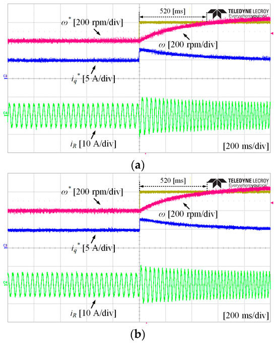
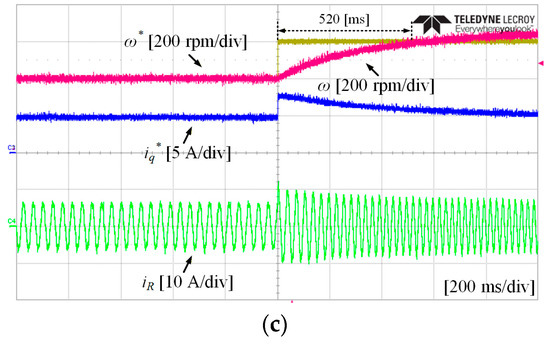
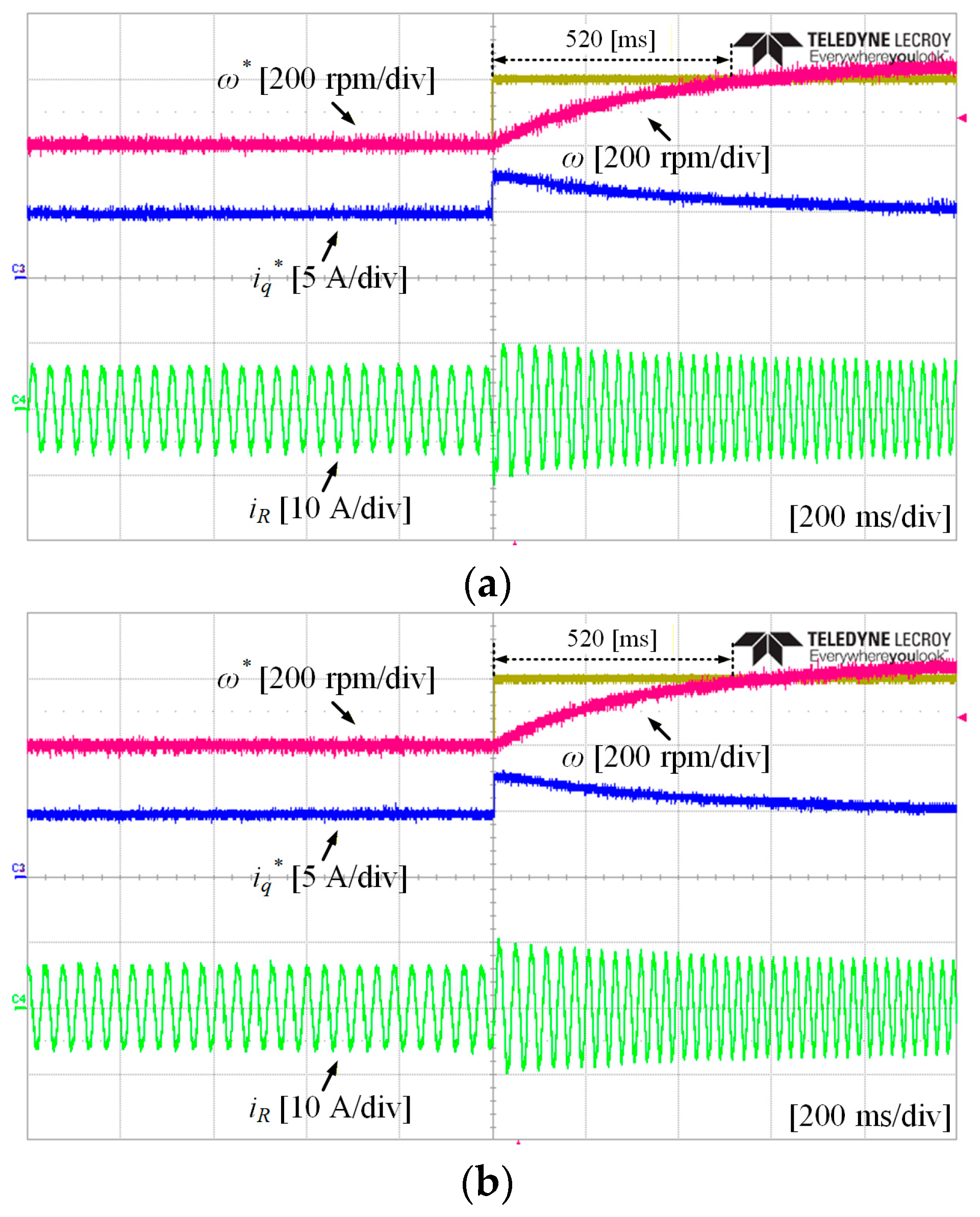
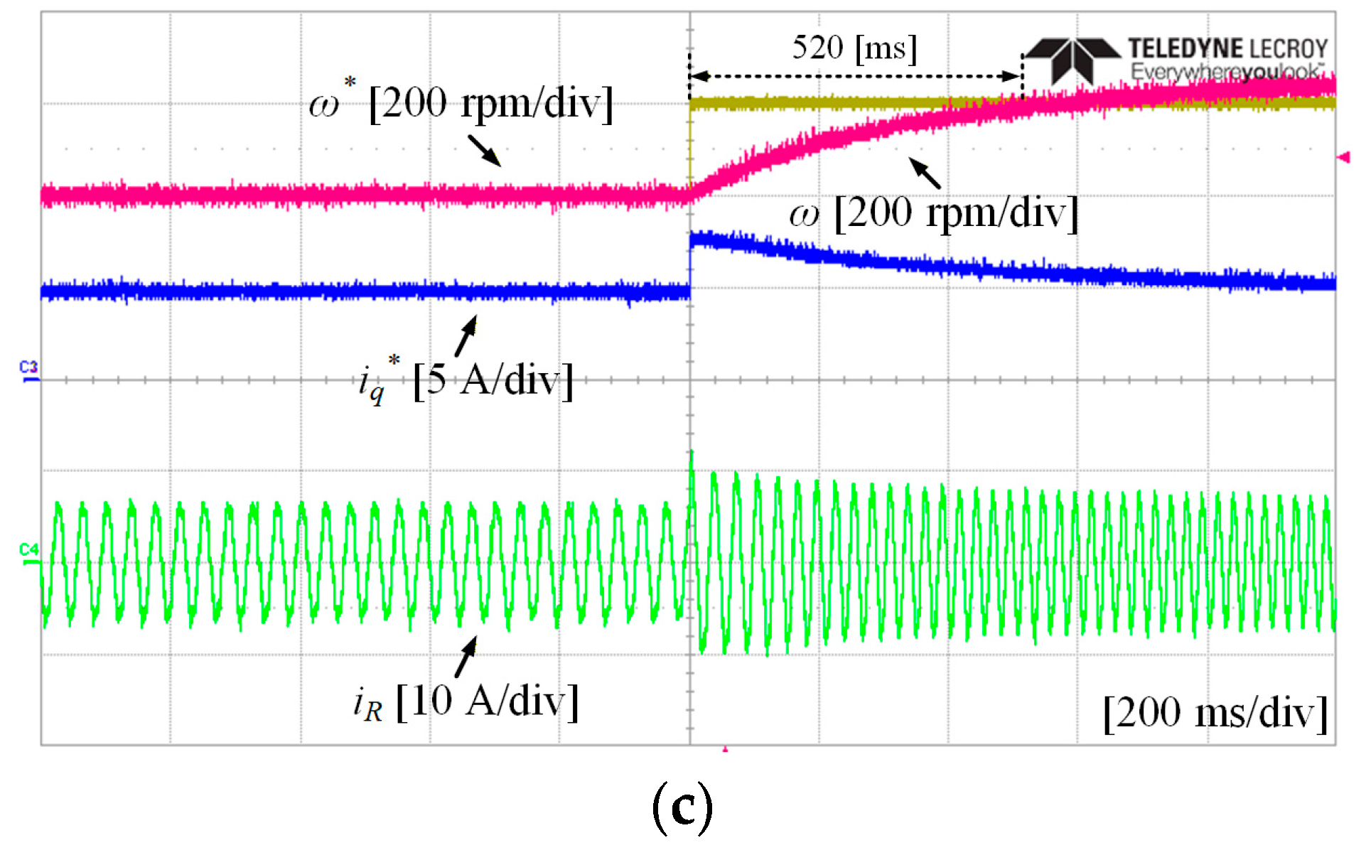
Figure 20 presents the experimental results of the transient-state response of the PMSM under a 10 Nm load. The results present a comparison between the various switching functions when using the SMC method using. Similarly, the ω* was changed from 400 rpm to 600 rpm. The coefficients were chosen to provide the highest responsiveness without causing chattering. Figure 20a presents experimental results of the SMC method using the saturation function, where the coefficient α was set to 3, and ω reaches ω* in 520 ms. Figure 20b presents experimental results of the SMC method using the hyperbolic function, where the coefficient β was set to 1, and ω reaches ω* in 520 ms. Figure 20c presents experimental results of the SMC method using the sigmoid function, where the coefficient γ was set to 1, and ω reaches ω* in 520 ms. The results of all switching functions were similar because the optimal coefficients were determined for each case.
Figure 20.
Experimental results of the transient-state response of the PMSM under a 10 Nm load: (a) SMC method using the saturation function; (b) SMC method using the hyperbolic function; (c) SMC method using the sigmoid function.
Figure 21 presents the experimental results of the steady-state response of the PMSM under a 10 Nm load for comparison of the chattering behavior in iq* for the (a) PI controller and (b) SMC method using the signum function. Both controllers are controlled normally in the steady state, but the SMC method using the signum function exhibits chattering in iq*.
Figure 21.
Experimental results of the steady-state response of the PMSM under a 10 Nm load for comparison of the chattering behavior in iq*: (a) PI controller; (b) SMC method using the signum function.
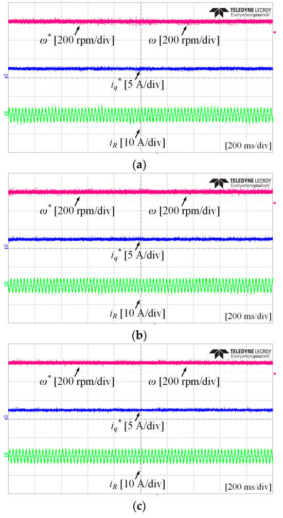
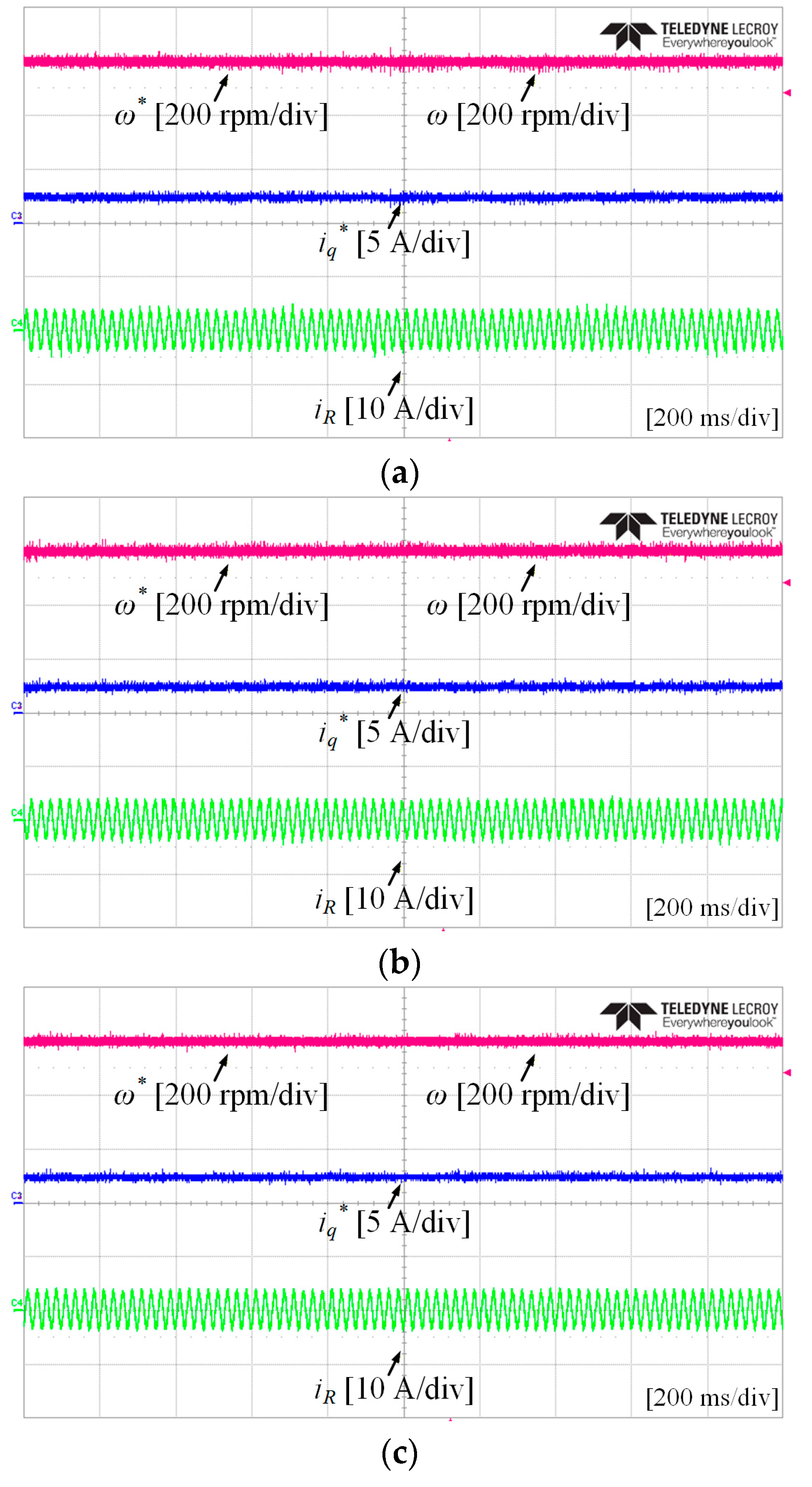
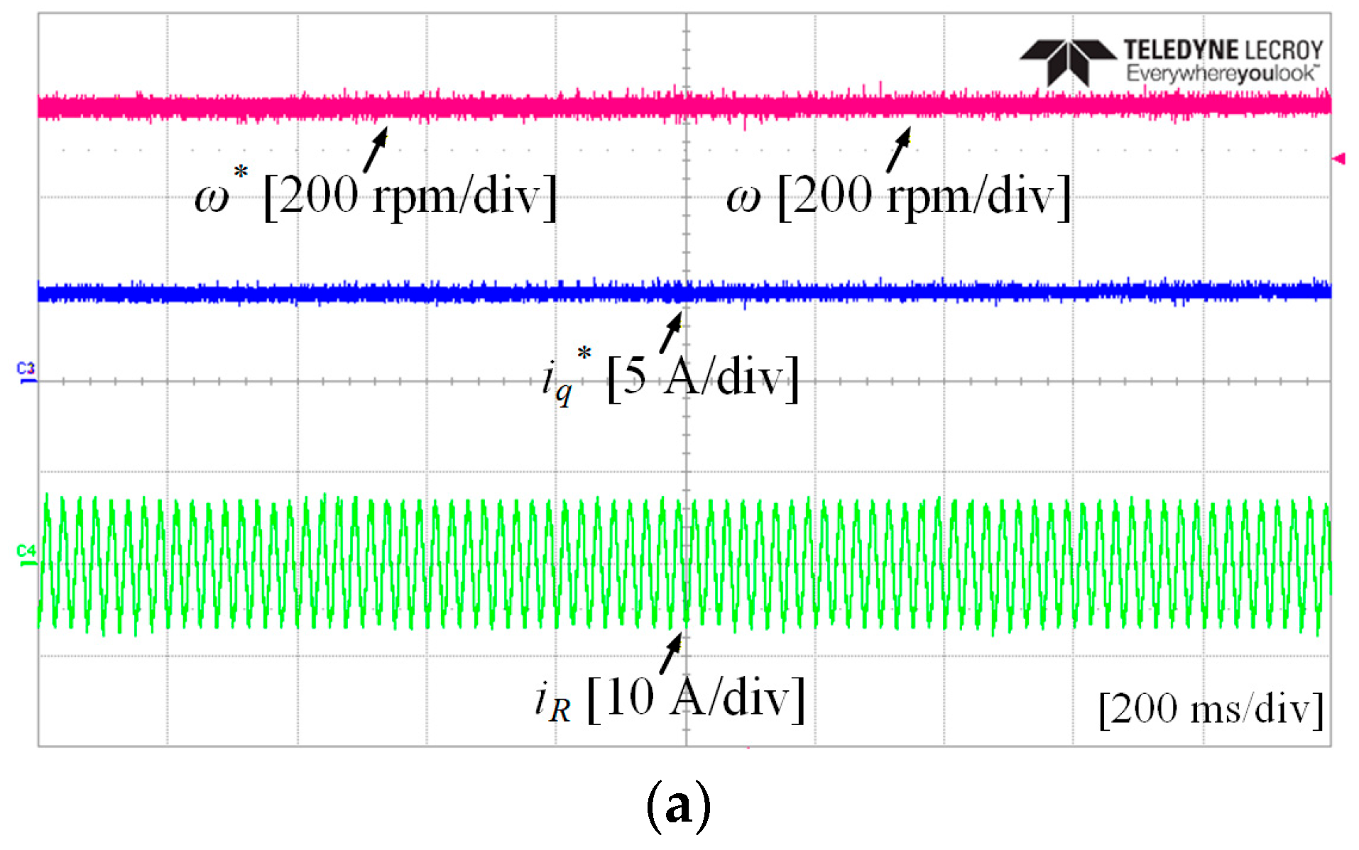
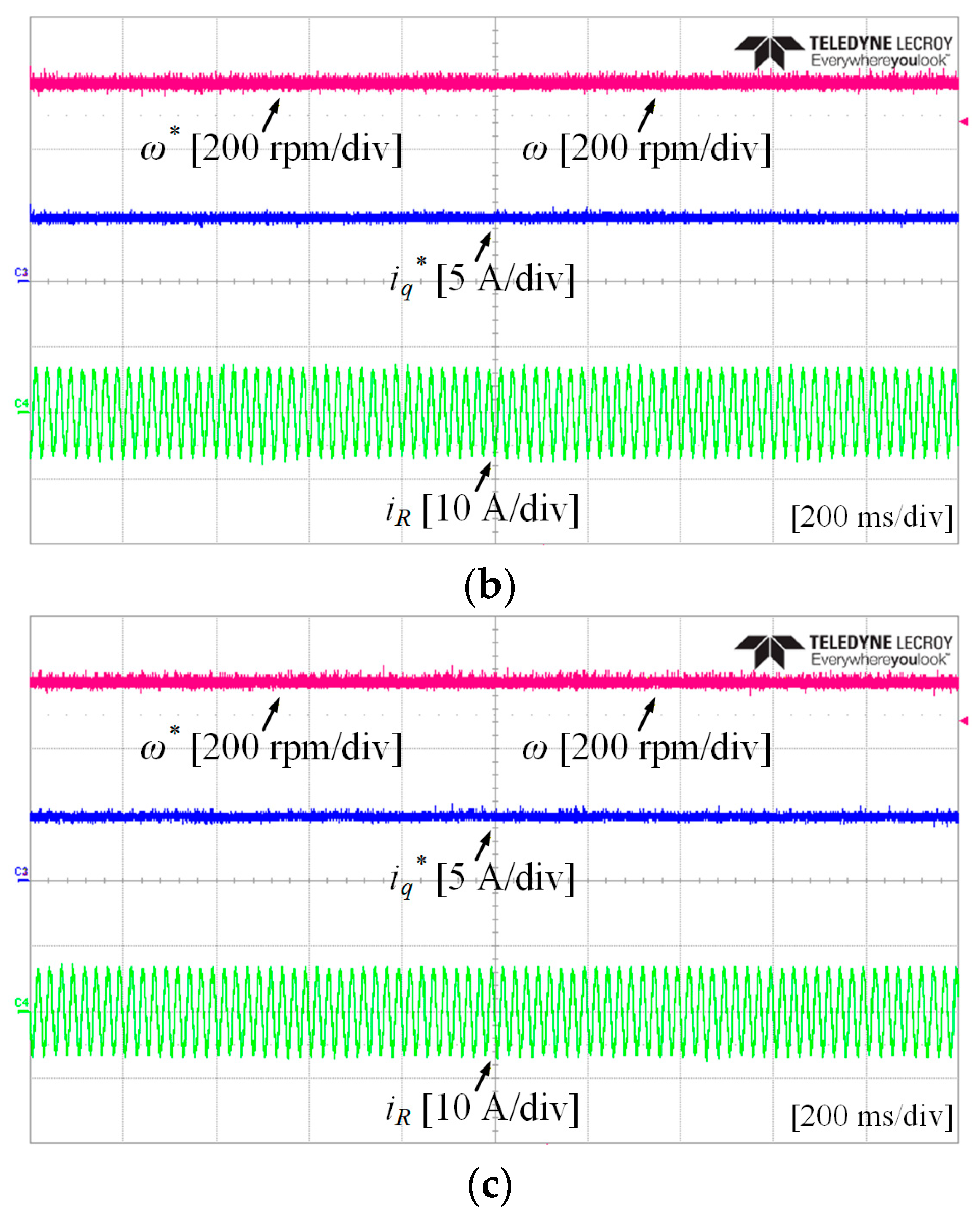
Figure 22 presents the experimental results of the steady-state response of the PMSM under a 10 Nm load for comparison of chattering behavior in iq* for (a) SMC method using the saturation function, (b) SMC method using the hyperbolic function and (c) SMC method using the sigmoid function. Similar to the 5 Nm case, chattering is not observed in iq and iq* for all switching functions, showing the same chattering suppression under a higher load condition.
Figure 22.
Experimental results of the steady-state response of the PMSM under a 10 Nm load for comparison of the chattering behavior in iq*: (a) SMC method using the saturation function; (b) SMC method using the hyperbolic function; (c) SMC method using the sigmoid function.
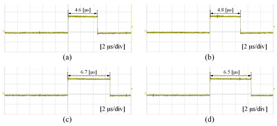
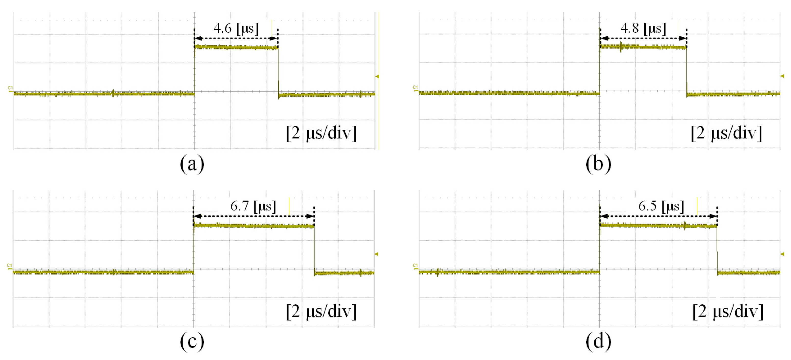
Figure 23 presents a comparison of the computational burden using various switching functions. The computational burdens of the signum, saturation, hyperbolic, and sigmoid functions are 4.6 μs, 4.8 μs, 6.7 μs and 6.5 μs, respectively. The signum function shows the shortest computation time among various switching functions because it only involves simple logical operations without nonlinear calculations. The saturation function shows a slightly increased computational burden compared with the signum function, as it requires additional calculations to limit the control input within a boundary layer. In contrast, the hyperbolic and sigmoid functions require longer computation times because they include exponential functions, which are computationally demanding. The signum function is simple to implement and provides the lowest computational burden. However, chattering occurs with the signum function. Therefore, alternative switching functions are employed. Among them, the saturation function provides a favorable balance between the chattering reduction and computational efficiency. Additionally, Table 3 presents the experimental performance comparison under a 10 Nm load.
Figure 23.
Comparison of computational burdens using various switching functions: (a) signum function; (b) saturation function; (c) hyperbolic function; (d) sigmoid function.
Table 3.
Experiment performance comparison under a 10 Nm load.
7. Conclusions
This paper proposes chattering reduction using various switching functions in the sliding mode control method for PMSM drives. In conventional SMC methods, the signum function is typically used as the switching function. Although this can improve the responsiveness compared with a PI controller, chattering may occur. This chattering can increase mechanical vibrations in the system, cause power loss, and degrade overall performance. By employing saturation, hyperbolic, and sigmoid switching functions, the responsiveness can be improved without chattering. Among them, the saturation switching function provides a favorable balance between control performance and computational burden, making it the most suitable choice for practical implementation. The effectiveness of the proposed SMC method with various switching functions has been verified through simulation and experimental results.
Author Contributions
Conceptualization, software, simulation validation, writing—original draft preparation, and visualization, G.Y.; experimental validation, Y.B. All authors have read and agreed to the published version of the manuscript.
Funding
This research was supported by the National Research Foundation of Korea(NRF) grant funded by the Korea government(MSIT) (No. RS-2025-23323395).
Data Availability Statement
The original contributions presented in this study are included in the article. Further inquiries can be directed to the corresponding author.
Conflicts of Interest
The authors declare no conflicts of interest.
References
- Zhou, P.; Xu, Y.; Zhou, G. Research on High Power Density Design Method of PMSM Based on the Highly Saturated Motor Core. IEEE Trans. Ind. Electron. 2025, 72, 14061–14072. [Google Scholar] [CrossRef] [Scilit]
- Yu, H.; Li, S.; Xu, Y.; Zhang, Z.; Mu, H.; Han, W. Time-Frequency Domain Lightweight Dual-Branch MSCFormer for PMSM ITSC Fault Diagnosis. IEEE Trans. Ind. Electron. 2026, 73, 94–105. [Google Scholar] [CrossRef] [Scilit]
- Liu, S.; Song, Z.; Liu, Y.; Chen, Y.; Liu, C. Flux-Weakening Controller Design of Dual Three-Phase PMSM Drive System With Copper Loss Minimization. IEEE Trans. Power Electron. 2023, 38, 2351–2363. [Google Scholar] [CrossRef] [Scilit]
- Hu, S.; Xiong, M.; Liang, Z.; He, X. Torque Distributed Control Strategy for the Dual Three-Phase PMSM in Hybrid Energy Storage System Application. IEEE Trans. Ind. Electron. 2020, 67, 2544–2552. [Google Scholar] [CrossRef] [Scilit]
- Rubio, F.; Pereda, J.; Mora, A.; Rojas, F. Optimal Switching Sequence MPC of a Three- Port-Converter for Variable-Speed PMSM With Hybrid Energy Storage. IEEE Trans. Power Electron. 2025, 40, 5069–5079. [Google Scholar] [CrossRef] [Scilit]
- Zhao, S.; Huang, X.; Fang, Y.; Zhang, H. DC-Link-Fluctuation-Resistant Predictive Torque Control for Railway Traction Permanent Magnet Synchronous Motor in the Six-Step Operation. IEEE Trans. Power Electron. 2020, 35, 10982–10993. [Google Scholar] [CrossRef] [Scilit]
- Lin, S.; Fang, X.; Wang, X.; Yang, Z.; Lin, F. Multiobjective Model Predictive Current Control Method of Permanent Magnet Synchronous Traction Motors With Multiple Current Bounds in Railway Application. IEEE Trans. Ind. Electron. 2022, 69, 12348–12357. [Google Scholar] [CrossRef] [Scilit]
- Zhang, G.; Liu, C.; Yuan, D.; Li, J. Mixed-Sensitivity H∞ Position Control for PMSM Based on Triple-Loop Structure With Anti-Windup PI and Robust Outer Loop Design. IEEE Access 2025, 13, 203547–203557. [Google Scholar] [CrossRef] [Scilit]
- Wen, J.; Yuan, X.; Niu, S.; Chan, W.L. A Robust Complex Vector PI Current Controller With Deadbeat Response for PMSM Drives. IEEE Trans. Ind. Electron. 2025, 72, 4671–4681. [Google Scholar] [CrossRef] [Scilit]
- Yang, C.; Liu, W.; Song, B.; Xie, X.; Niu, S.; Chau, K.T. Signal-Injection-Based Efficient Direct-Determination of Controller Gains and Nonlinear Friction Compensation Values in SPMSM Drives. IEEE Trans. Power Electron. 2026, 41, 1627–1633. [Google Scholar] [CrossRef] [Scilit]
- Li, Z.; Wang, F.; Ke, D.; Li, J.; Zhang, W. Robust Continuous Model Predictive Speed and Current Control for PMSM With Adaptive Integral Sliding-Mode Approach. IEEE Trans. Power Electron. 2021, 36, 14398–14408. [Google Scholar] [CrossRef] [Scilit]
- Zhang, Y.; Li, S.; Yi, W.; Yang, Y.; Cao, K.; Luo, B. A Robust Model Predictive Current Closed-Loop Control With Parameter Estimation Strategy Based on Immune Chaotic Antipredator PSO for PMSM. IEEE Trans. Power Electron. 2025, 40, 1836–1848. [Google Scholar] [CrossRef] [Scilit]
- Yan, H.; Xu, Y.; Cai, F.; Zhang, H.; Zhao, W.; Gerada, C. PWM-VSI Fault Diagnosis for a PMSM Drive Based on the Fuzzy Logic Approach. IEEE Trans. Power Electron. 2019, 34, 759–768. [Google Scholar] [CrossRef] [Scilit]
- Suleimenov, K.; Do, T.D. Design and Analysis of a Generalized High-Order Disturbance Observer for PMSMs With a Fuzy-PI Speed Controller. IEEE Access 2022, 10, 42252–42260. [Google Scholar] [CrossRef] [Scilit]
- Tang, P.; Zhao, Z.; Li, H. Short-Term Prediction Method of Transient Temperature Field Variation for PMSM in Electric Drive Gearbox Using Spatial-Temporal Relational Graph Convolutional Thermal Neural Network. IEEE Trans. Ind. Electron. 2024, 71, 7839–7852. [Google Scholar] [CrossRef] [Scilit]
- Raia, M.R.; Ruba, M.; Nemes, R.O.; Martis, C. Artificial Neural Network and Data Dimensionality Reduction Based on Machine Learning Methods for PMSM Model Order Reduction. IEEE Access 2021, 9, 102345–102354. [Google Scholar] [CrossRef] [Scilit]
- Utkin, V.I. Sliding Mode Control Design Principles and Applications to Electric Drives. IEEE Trans. Ind. Electron. 1993, 40, 23–36. [Google Scholar] [CrossRef] [Scilit]
- Li, K.; Ding, J.; Sun, X.; Tian, X. Overview of Sliding Mode Control Technology for Permanent Magnet Synchronous Motor System. IEEE Access 2024, 12, 71685–71704. [Google Scholar] [CrossRef] [Scilit]
- Wang, A.; Wei, S. Sliding Mode Control for Permanent Magnet Synchronous Motor Drive Based on an Improved Exponential Reaching Law. IEEE Access 2019, 7, 146866–146875. [Google Scholar] [CrossRef] [Scilit]
- Zhang, Z.; Yang, X.; Wang, W.; Chen, K.; Cheung, N.C.; Pan, J. Enhanced Sliding Mode Control for PMSM Speed Drive Systems Using a Novel Adaptive Sliding Mode Reaching Law Based on Exponential Function. IEEE Trans. Ind. Electron. 2024, 71, 11978–11988. [Google Scholar] [CrossRef] [Scilit]
- Wang, Y.; Feng, Y.; Zhang, X.; Liang, J. A New Reaching Law for Antidisturbance Sliding-Mode Control of PMSM Speed Regulation System. IEEE Trans. Power Electron. 2020, 4, 4117–4126. [Google Scholar] [CrossRef] [Scilit]
- Wang, Q.; Yu, H.; Wang, M.; Qi, X. An Improved Sliding Mode Control Using Disturbance Torque Observer for Permanent Magnet Synchronous Motor. IEEE Access 2019, 7, 36691–36701. [Google Scholar] [CrossRef] [Scilit]
- Junejo, A.K.; Xu, W.; Mu, C.; Ismail, M.M.; Liu, Y. Adaptive Speed Control of PMSM Drive System Based a New Sliding-Mode Reaching Law. IEEE Trans. Power Electron. 2020, 35, 12110–12121. [Google Scholar] [CrossRef] [Scilit]
- Yim, J.; You, S.; Lee, Y.; Kim, W. Chattering Attenuation Disturbance Observer for Sliding Mode Control: Application to Permanent Magnet Synchronous Motors. IEEE Trans. Ind. Electron. 2023, 70, 5161–5170. [Google Scholar] [CrossRef] [Scilit]
- Wang, S.; Wang, Z.; Niu, X.; Zhu, Y.; Lu, W.; Liu, Y. An Adaptive Sliding Mode Control for PMSM Servo Systems Beyond the Inertia Ratio Limit. IEEE Trans. Power Electron. 2025, 40, 16352–16366. [Google Scholar] [CrossRef] [Scilit]
- Kang, Z.; Lin, X.; Shen, X.; Liu, Z.; Gao, Y.; Liu, J. Event-Triggered Generalized Super-Twisting Sliding Mode Control for Position Tracking of PMSMs. IEEE Trans. Ind. Inform. 2025, 21, 5701–5711. [Google Scholar] [CrossRef] [Scilit]
- Kang, Z.; Lin, X.; Liu, Z.; Shen, X.; Gao, Y.; Liu, J. Adaptive Generalized Super-Twisting Sliding Mode Control for PMSM Drives. IEEE Trans. Energy Convers. 2025, 1–11. [Google Scholar] [CrossRef] [Scilit]
- Lin, X.; Shen, X.; Liu, Z.; Gao, Y.; Kang, Z.; Liu, J. Observer-Based Prescribed Performance Speed Control for PMSMs: A Data-Driven RBF Neural Network Approach. IEEE Trans. Ind. Inform. 2024, 20, 7502–7512. [Google Scholar] [CrossRef] [Scilit]

Disclaimer/Publisher’s Note: The statements, opinions and data contained in all publications are solely those of the individual author(s) and contributor(s) and not of MDPI and/or the editor(s). MDPI and/or the editor(s) disclaim responsibility for any injury to people or property resulting from any ideas, methods, instructions or products referred to in the content. |
© 2026 by the authors. Licensee MDPI, Basel, Switzerland. This article is an open access article distributed under the terms and conditions of the Creative Commons Attribution (CC BY) license.