


Abstract
In this work, we present the design and evaluation of the X2000, a new development kit created to simplify and accelerate research for advanced driver-assistance systems (ADAS). The X2000 is a complete ADAS development kit for the Ford Mach-E. It includes a forward-facing vehicle-mounted camera, vehicle-mounted AI computer, controller area network flexible data-rate (CAN-FD) and 12 V power connections, and a CAN-FD interface to the vehicle’s forward radar. Central to the kit is a novel ADAS software architecture designed for readability and extensibility. Included in the design are software modules for the following: (1) camera and radar interfacing; (2) image processing; (3) AI model inference; (4) data logging; (5) steering and velocity planning; (6) low-level vehicle controls for steering, acceleration, and braking; (7) lane centering visualization to the car’s 17-inch touchscreen. To build on a proven system, the X2000 integrates the AI model, planner, low-level controls, and radar interfacing software from Openpilot. We build on the excellent work of the Openpilot team while creating a highly simplified system. Openpilot features 17 software processes and 77 inter-process messages, while the X2000 uses 6 processes and 7 inter-process messages.
1. Introduction
Outfitting a vehicle for ADAS development is a time- and resource-intensive process. It requires installing a drive-by-wire control system, integrating and calibrating cameras and sensors, developing the ADAS software, and validating the complete system for safe road testing. There are existing solutions that seek to address these challenges. The X2000 leverages aspects of these existing systems while providing a novel software architecture for faster ADAS development with the goal of lowering the barrier to entry for the creation of new ADAS research and development programs.
Existing solutions include three primary options:
- Nvidia DRIVE developer kit;
- Baidu Apollo;
- Comma.ai Comma Four running Openpilot.
Nvidia DRIVE includes state-of-the-art ADAS hardware along with advanced ADAS development software. It is accessible solely to approved developers of automated driving software [1]. DRIVE also provides a list of supported sensors, yet these require test vehicle integration and calibration [2]. Finally, DRIVE is restricted to Nvidia’s C-based code and toolchains [3]. C requires more code for a given task than Python, which can limit rapid progress [4].
The Baidu Apollo features an extensive and highly capable open-source software system [5]. They also have their own hardware platform and support a variety of added sensors [6]. While Apollo is accessible and capable for developers, its open-source software is written in C++ [5]. C++ also requires more code for a given task than Python [4]. Longer code combined with their deep network of sensors and computers can increase the development time [4,5].
Openpilot 0.10.1 from Comma.ai offers an open-source software system based on Python 3.12 with built-in drive-by-wire, camera, and radar interfacing [7]. For a given task, Python has shown itself to be a more efficient programming language, by lines of code, than other languages, which means software using it can be developed faster [4]. Openpilot’s computer vision inference model and control system has been validated on over 300 million miles of driving, which gives developers a strong foundation for building ADAS software [7]. This research directly observes a challenge for developers that is presented by Openpilot. Openpilot has a complex software architecture that includes 17 different processes with 77 different messages communicated between them [8,9]. This architecture makes extensibility of the software more difficult due to the complex interactions throughout the system. Openpilot is also only plug-and-play with the Comma Four as a hardware platform, which is a proprietary device from Comma.ai [10].
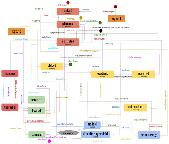
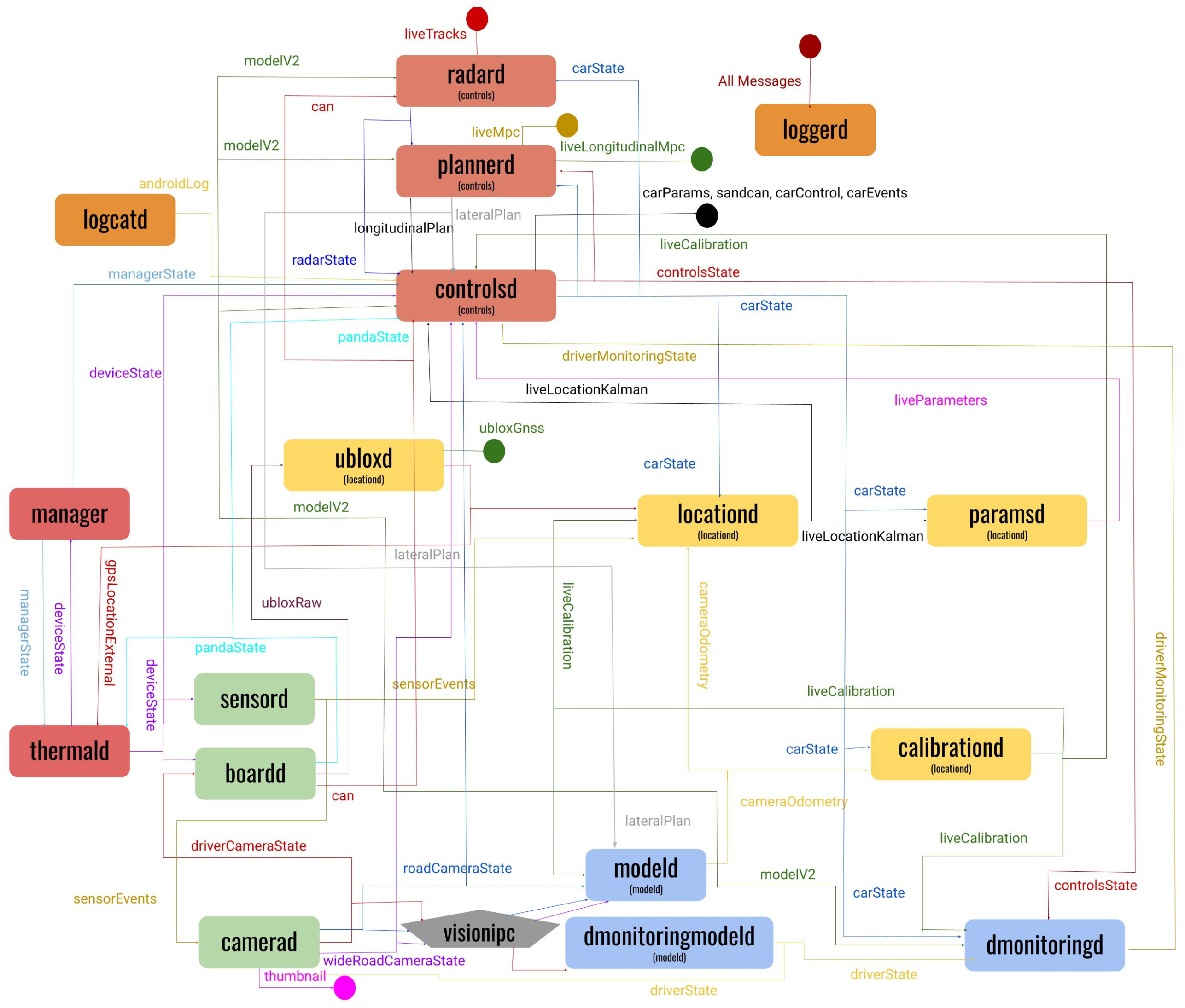
The X2000 combines the same state-of-the-art system-on-chip as the Nvidia DRIVE with the capabilities and development potential of Openpilot while optimizing it for rapid development and extensibility. The X2000 leverages its AI inference model, steering and velocity planning, and low-level vehicle control methods. Openpilot has 17 separate processes, while the X2000’s architecture uses only 6 [8]. The architecture of Openpilot is shown in Figure 1 [11]. Reducing the number of processes aims to make the code more comprehensible for new developers and more extensible by reducing the complexity of the architecture.
Figure 1.
The software architecture of Openpilot.
The X2000’s architecture includes the diffusion-transformer-based computer vision inference model from Openpilot for predicting road segmentation, object detection, future trajectory, and vehicle actions [12]. It runs on an Nvidia Jetson AGX Orin using Jetpack 6.2 instead of Comma.ai’s proprietary hardware. Dedicated software modules facilitate camera and radar interfacing, inference by the AI model, steering and velocity planning, drive-by-wire vehicle control, data logging, and user interface display on the vehicle’s center screen. It is integrated and pre-calibrated to be used immediately with the Ford Mach-E.
Its Jetson AI platform provides standardized connections for power, CAN-FD, and automotive-grade GMSL2 cameras. The CAN-FD interface uses a modular software and hardware design to simplify switching between test vehicles. A pre-calibrated road-facing GMSL2 camera is included to enable the computer vision tasks within the reference software. While the Comma Four uses two separate cameras to capture images for inference, the software design in this research projects the images from a single camera into the two views needed for the computer vision model. This single camera method facilitates a simpler install process and cheaper hardware cost.
This paper first discusses the technology and methodology behind the design of the X2000. Next, test results are presented that aim to provide an understanding of how well the X2000 can process data and handle computational loads while performing real-time ADAS testing. Finally, the results of that testing are analyzed, conclusions are drawn from them, and future research possibilities are discussed.
2. Materials and Methods
2.1. Software Reference Design
The X2000’s ADAS software reference design focuses on simplified, understandable code. It is essential that the structure of the code and what each process does can be interpreted and modified easily by developers. Other development kits such as the Nvidia DRIVE and Baidu Apollo use C or C++, which require more code compared to Python to perform the same tasks [3,4,5]. Openpilot uses Python but is designed with a network of 17 different processes with 77 inter-process messages as seen in Figure 1 [8,9,11]. The X2000 achieves its goal of simplicity and extensibility by restructuring Openpilot’s Python source code into just 6 main processes and three shared memory partitions with 7 inter-process messages.
Openpilot is an open-source Level 2 ADAS system from Comma.ai that runs on their proprietary hardware device called the Comma Four [7]. Openpilot’s software is available to the public under the MIT license [13]. This license allows Openpilot’s software to be used and developed for independent research projects such as the X2000 [14]. Openpilot 0.10.1 is the Openpilot version used for this research [7]. The deep learning model behind Openpilot, and by extension the X2000, has been trained and validated across over 300 million miles of driving, 56% of which were driven fully by Openpilot’s software under driver supervision [7]. The X2000, having a well-established model to build off of, is essential for confidence in its performance and having a strong foundation to develop from.
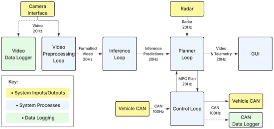
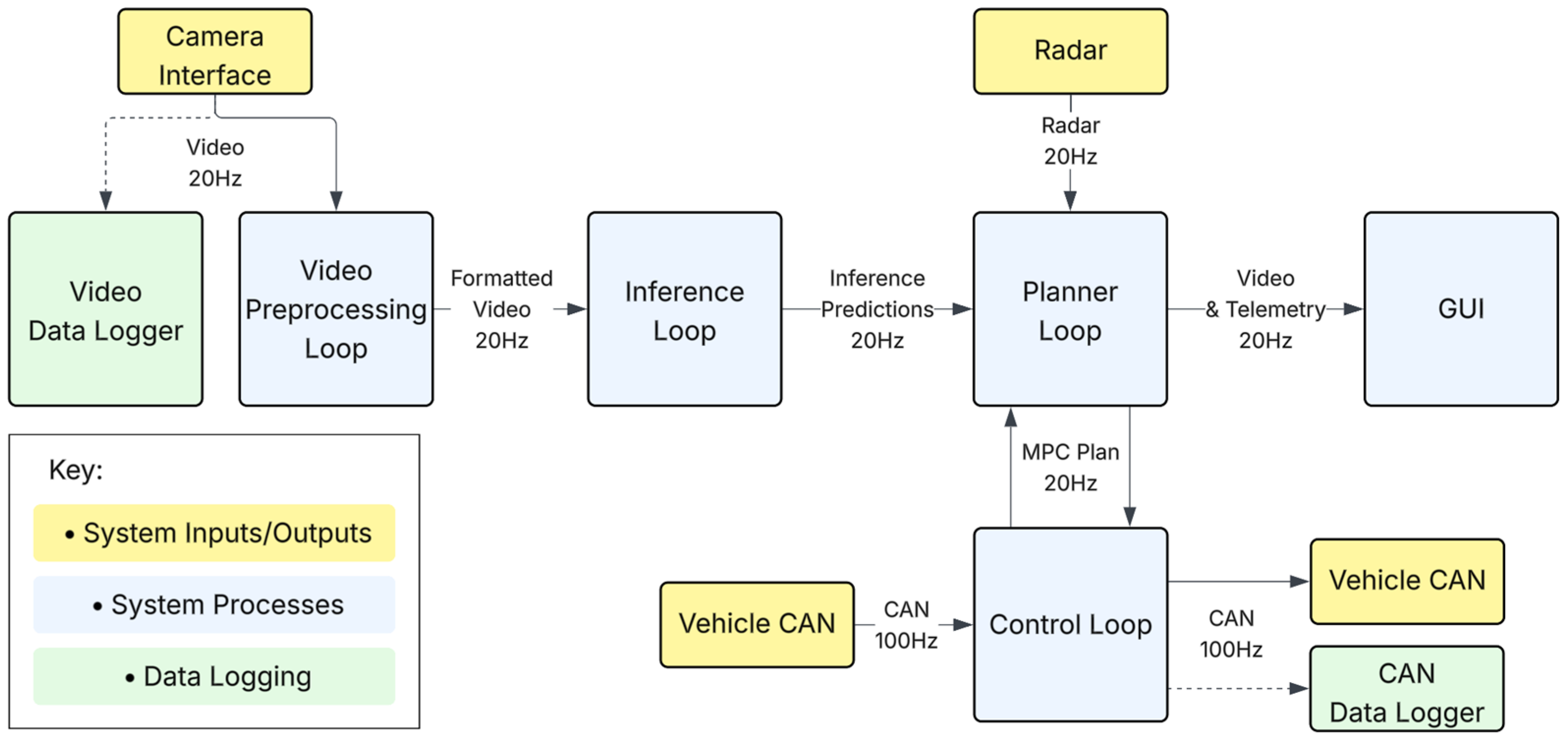
Each major process and data structure of the X2000’s software is written using the class data structure. The overall structure and data flow of the software is shown in Figure 2. The main processes include the following:
Figure 2.
Flow of data in the main processes of the X2000’s software.
- Preparing video frames for inference at 20 Hz;
- Performing computer vision inference at 20 Hz;
- Calculating vehicle control plans from inference outputs, vehicle state data, and radar using a model predictive control (MPC) algorithm at 20 Hz;
- Processing CAN-FD inputs and outputs to execute control plans at 100 Hz;
- Formatting live camera, inference, and control data to be displayed on the vehicle’s center console screen at 20 Hz;
- Logging video and CAN-FD data while driving at 20 Hz and 100 Hz, respectively.
The video preprocessing, inference, and user interface processes communicate camera data through shared memory. Shared system memory is established by allocating the amount of memory the shared data needs to a specific memory address range in RAM. The shared_memory module of the multiprocessing Python library is used to define the shared memory partitions with globally known unique identifiers [15]. At startup, each process finds the location of the data it needs in memory using the global identifier. Each partition has its own set of methods defined for initialization, reading, and writing. Shared memory allows each process to run independently. They can be stopped and started as needed. This makes the system safer and faster to develop. If a process has stopped or failed, it can be restarted without the rest of the system also failing or needing to restart.
In addition, the control and inference processes share data via the message passing software module of Openpilot 0.10.1 named cereal. The control process sends vehicle state and vehicle control predictions as a message, and the inference process sends the model predictions and planner outputs as a message to the control process. The message passing mechanism ensures that only the latest data is processed by each. They run at different rates as the inference process uses a trained model that features images spaced 50 ms apart. The control process features control decisions that need to be communicated at the vehicle’s predetermined frequency for each CAN-FD message, as defined in the manufacturer’s DBC file.
The overall flow of data starts with the camera interface reading video from the GMSL2 deserializer. The video preprocessing loop uses the original wide-angle image from the camera to generate a second narrow-angle image. It does this by cropping, upsampling, and applying a lens distortion projection matrix to the original image to mimic a narrow-angle lens. The camera produces 1920 by 1200 pixel Blue-Green-Red-Alpha (BGRA) images, which are converted to two images following reprojection. These are then converted to two 512-by-256 YUV images as required by the Openpilot inference model. For display to the vehicle’s screen, the original BGRA image is converted to RGB. The model’s 3D predictions are overlaid onto the RGB image based on the camera’s intrinsic and extrinsic characteristics. The formatted video is passed to the inference loop through shared memory.
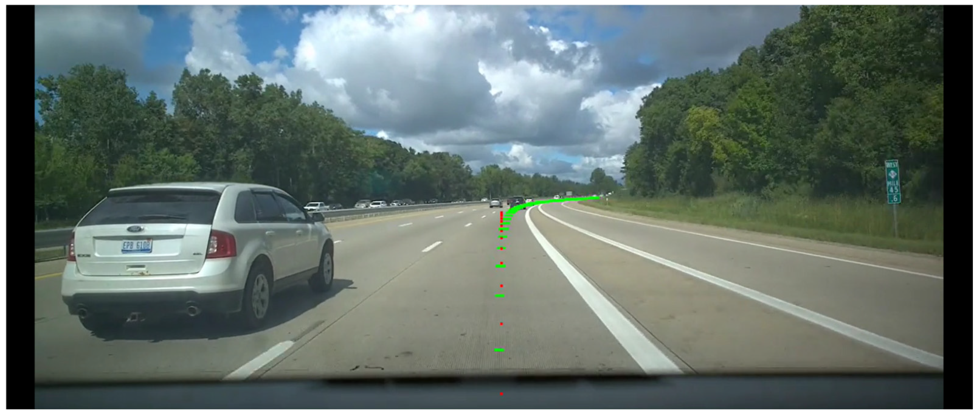
The inference loop runs computer vision inference on the wide and narrow YUV images. The model, developed originally for Openpilot, uses two transformer networks [12]. The first network’s architecture is based on FastViT [16]. It predicts features about the driving scene including the lane lines, road edges, lead car positions, and the future trajectory of the test vehicle [12]. The second network is a diffusion transformer that takes the last five seconds of outputs from the first transformer as an input [12]. It predicts the final output of the model, which includes velocity targets and the desired curvature for the test vehicle to follow. An image depicting the steering and velocity predictions from the X2000’s GUI is shown in Figure 3. The predictions are sent to the planner process so that the control and MPC algorithm policies can be applied to them.
Figure 3.
An image from the X2000’s GUI depicting the forward camera’s view with an overlay of the steering plans (green) and velocity plans (red).
The planner process splits the control problem into longitudinal and lateral pipelines, each using algorithmic strategies to maintain stable control of the vehicle. For longitudinal control, the system implements a Proportional–Integral–Derivative (PID) algorithm coupled with a feedforward component. This controller minimizes the error between the target acceleration from the acceleration plan and the vehicle’s current acceleration The proportional term addresses immediate error, the integral term eliminates steady-state offset by accumulating error over time, and the derivative term provides damping to prevent overshoot, while the feedforward term uses the raw target acceleration to provide a baseline command that improves system responsiveness. When the driver hits the throttle or brakes, the system stops sending longitudinal control commands.
The lateral control pipeline utilizes a Feedforward Geometric Control algorithm based on a Dynamic Bicycle Model [17]. Rather than relying on a traditional PID loop to correct steering error after it occurs, this model performs a physics-based transformation. It maps validated curvature targets directly to specific steering wheel angles by solving the equations of motion for a two-wheeled vehicle representation, accounting for the mass, wheelbase, and steering ratio. This open-loop approach allows the vehicle to preemptively align with the desired trajectory. System stability is enforced saturation thresholds that serve as safety governors. They flag any deviation between the commanded and measured steering angles that exceed a 2.5° threshold every 10 ms. The lateral control outputs are paused while steering is controlled by the driver and resumed when the driver stops applying torque to the wheel.
The control loop handles reading and decoding CAN-FD inputs from the vehicle into vehicle state data structures. It also uses the outputs from the planner process to inform control decisions, which are then encoded as CAN-FD outputs. When a plan is received, the vehicle state data structures are used to determine what attributes of the vehicle need to be updated to satisfy the plan. Once the required changes are determined, the CAN-FD messages containing the updated attributes are populated, encoded with the manufacturer’s DBC file specifications, and sent over the CAN-FD network. The outputs are currently sent over a virtual CAN-FD channel that matches the vehicle. Once validation of performance and safety on a real vehicle is complete, the output will be sent on the vehicle’s CAN-FD network to control it.
2.2. Extensibility
For a developer to replace the X2000’s inference model with their own, they must create two sub-models with inputs and outputs that align with the two sub-model being used from Openpilot [18]. The first model will be referred to as the vision model and the second as the policy model, although developers do not necessarily have to keep that same model structure. The inputs to the initial vision model must include two pairs of 512-by-256 resolution images in the YUV color space [18]. One pair contains the current narrow and wide views and the other pair contains the narrow and wide views from the last frame. The inputs to the policy model include the following:
- Five seconds of one-hot encoded desired actions at 100 Hz with shape (100, 8);
- A one-hot encoded indicator for left or right-handed traffic with shape (2);
- Speed and steering delays with shape (2);
- A feature buffer for the last five seconds of feature data at 20 Hz with shape (100, 512) [18].
The outputs must be 33 future trajectory and velocity points at 50 ms intervals. Included are the orientation, angular velocity, position, linear velocity, and linear acceleration [19]. Each includes a value for three axes of movement to create an output of shape (33, 15) [19]. The sub-models must be in the ONNX file type to be loaded in place of the original sub-models.
To integrate a new sensor, a hardware connection is made using the external connectors of the X2000. Python libraries such as python-can, socket, or pyserial are used to communicate with the sensor using its respective communication protocol. When following the X2000’s software architecture, a developer would create a software module for the sensor with a class that can be imported into any other files as needed. The class would include methods to perform the following:
- Initialize the sensor connection and class attributes;
- Read data from the sensor and process it based on vehicle calibration requirements;
- Write data to the sensor (if applicable);
- Update the sensor’s class attributes with the data being collected.
Other specialized routines can be included as needed. By using this architecture for sensor integration, an ADAS process can have the new sensor added to it with as few as three lines of code. One line imports the sensor class, another creates the sensor object using the imported class, and the third calls the sensor class’s read method to get the sensor data.
2.3. AI Compute Hardware
The X2000 uses an Nvidia Jetson AGX Orin system-on-chip. Its GPU has 1792 CUDA cores and 56 tensor cores [20]. Its CPU is an 8-core Arm Cortex-A78AE processor running at 2.2 GHz with 2 MB of L2 cache and 4 MB of L3 cache. It has 32 GB of LPDDR5 RAM running at 204.8 GB/s shared by the CPU and GPU [21]. There are 57 GB of eMMC storage and an additional option for 1 TB SSD of data storage. It also has automotive connectors to match the vehicle connectors for 12 V power, CAN-FD, and GMSL2 cameras. Desktop standard connectors are provided for bench-top use, including USB-A 3.0, USB-C, ethernet, and HDMI. Its operating system is Ubuntu 22.04. Development can be done directly on the X2000 with the standard desktop computer connections. Installing it in the vehicle only requires connecting the power, CAN-FD, and GMSL2 connectors to the vehicle’s wiring harnesses.
This Nvidia platform was chosen as it is specialized for edge AI applications [20,21]. The tensor cores of the GPU are dedicated to performing the fast, complex matrix computations required by deep learning models. It has features such as a deep learning accelerator (DLA) and programmable vision accelerator (PVA) that optimize how the hardware executes computations for deep learning and computer vision. This platform also enables the X2000’s software to leverage Nvidia’s AI libraries such as CUDA and TensorRT to take full advantage of the available hardware.
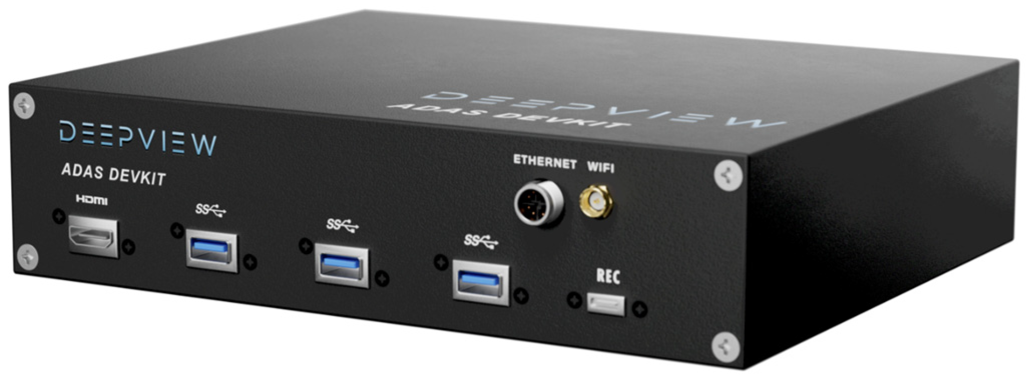
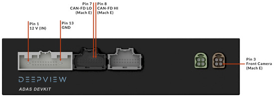
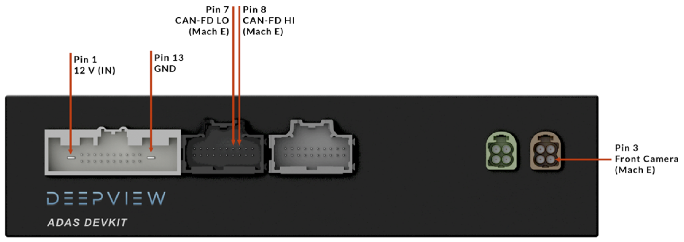
Figure 4 and Figure 5 show the overall design of the X2000. The Nvidia Jetson AGX Orin platform is implemented on a custom PCBA. The PCBA includes all the required connections for multiple GMSL2 cameras, the vehicle’s CAN-FD communication, and other typical computer IO. Currently the CAN-FD interface is compatible with the Ford Mach-E, taking the place of the vehicle’s stock ADAS ECU. The design can be adapted to other vehicles by changing the X2000’s CAN-FD connector to accept that vehicle’s stock CAN-FD harness connector. The DBC file and CAN-FD parsing software must also be changed to encode and decode that manufacturer’s CAN-FD messages.
Figure 4.
The X2000’s overall design including its display, USB, ethernet, and Wi-Fi antenna connectors.
Figure 5.
The X2000’s power, CAN-FD, and GMSL2 camera connectors.
2.4. CAN-FD Interface
The X2000 simulates a portion of its CAN-FD communication, while real control of a vehicle remains a work in progress. The interface reads real CAN-FD messages from the test vehicle and parses them for use by the ADAS software. The python-can library is used to create a virtual second CAN-FD network that matches the vehicle’s CAN-FD configuration. Once the control process calculates the required outputs to control the vehicle, they are sent over the virtual CAN-FD interface. Work is in progress to validate that the control commands generated are safe to use on a real test vehicle while driving and that they can be communicated on the CAN-FD bus without issues. End-to-end CAN-FD pipeline validation, simulated road testing, and real road testing validation are planned for February of 2026. Once the integrity and safety of the simulated control commands are validated, the complete testing of vehicle controls will be possible by updating the python-can settings to output to the vehicle’s CAN-FD channel instead of the virtual channel.
The X2000 receives the same CAN-FD inputs received by the stock ADAS ECU of the vehicle. This is enabled as the X2000 replaces the stock Ford Mach-E’s lane centering ECU This stock lane-centering ECU is referred to by Ford as Image Processing Module A or IPMA. The X2000’s CAN-FD and power connectors connect to the vehicle’s wiring harness containing the CAN-FD high, CAN-FD low, and power supply wires. The CAN-FD interface reads CAN-FD data packets every 10 ms. A filter on the inputs is used to ignore any received CAN-FD frames that are not relevant to what the X2000 needs. A DBC file contains manufacturer-specific information defining the CAN-FD messages utilized in the manufacturer’s vehicles [22]. That information is used to decode received CAN-FD frame inputs and to encode CAN-FD frame outputs created for vehicle control [22].
The X2000’s software reads relevant CAN-FD frames and uses the DBC file to parse them into useful data that can be stored in manufacturer-agnostic data structures. One data structure stores the data received via CAN-FD after it is decoded. This data structure has 74 parameters tracking characteristics about the vehicle that change as it drives, such as the speed, steering angle, and gas and brake pedal engagement. Another predefined data structure stores 120 parameters for vehicle characteristics that do not change such as vehicle dimensions, weight, steering characteristics, and acceleration thresholds.
The vehicle state model formed by this data helps the X2000’s control and inference processes to determine what the vehicle needs to do to drive along its target trajectory safely and efficiently. When those actions are determined, parameters for the vehicle’s specific CAN-FD frames are calculated and encoded using the DBC file. The encoding done with the DBC file ensures that the CAN-FD frames generated for control are in a format readable by the vehicle they are being created for [22].
2.5. Throttle-by-Wire & Brake-by-Wire Control
The X2000 simulates control of the throttle-by-wire and brake-by-wire systems using an acceleration CAN-FD message. The CAN-FD message includes values for the following:
- Total braking acceleration requested in m/s2;
- Acceleration requested in m/s2;
- Cruise control enabled or disabled;
- Allow resuming cruise control;
- Active deceleration request;
- Stop state request.
The braking acceleration limits are −20 m/s2 to 11.9449 m/s2. A negative braking acceleration request will apply the brake actuators more, and a positive value will release the brakes. The throttle has acceleration limits of −5 m/s2 to 5.23 m/s2. A negative acceleration request will ease the throttle actuator, and a positive value will engage it. The cruise control flags tell the powertrain ECU and braking ECUs whether to accelerate or decelerate the vehicle.
2.6. Electronic Power-Assisted Steering (EPAS) Control
The X2000 uses EPAS technology by providing target path data to the vehicle’s power-steering control module (PSCM). The X2000 performs inference on its video feed to determine the trajectory that the car should follow to stay centered in its lane, turn, or make a lane change. The X2000 creates a lateral control CAN-FD message that can be used to instruct the vehicle’s PSCM of how to control the EPAS system. The fields for steering adjustments in the CAN-FD message are the following:
- The vehicle’s target offset from the center of the lane in meters;
- The offset angle from the vehicle’s path in radians;
- The curvature the vehicle should follow in inverse meters (1/m);
- The rate of change of that curvature in inverse meters squared (1/m2);
- Enabling or disabling lateral control;
- How closely the vehicle should follow the given curvature;
- If the driver’s hands are on the wheel for safety.
2.7. GMSL2 Camera
The X2000 uses a GMSL2 camera manufactured by StereoLabs (San Francisco, CA, USA) called the ZED X One. Their ZED Link Duo GMSL2 deserializer receives the video feed from the camera [23]. The ZED X One has a resolution of up to 1920 by 1200 pixels [23]. Its stock lens has a 91° FOV diagonally, 80° horizontally, and 52° vertically. It records video at up to 60 FPS, which the X2000 takes advantage of by only sampling one of every three frames to guarantee the 20 FPS framerate expected by the reference computer vision model. The ZED X One has an integrated accelerometer that can be used for orientation calibration [23]. GMSL2 allows for fast, lossless video transfer, so the X2000’s computer can receive high image quality in real-time [24]. The camera mounts in the vehicle’s stock forward camera location to make integration simple. The images from the camera are cropped and projected to an additional narrow area of focus so the computer vision model can perform coarse and fine inference on the scene with a wide and narrow view, as required by the AI model provided by Openpilot 0.10.1.
2.8. Safety
Several safety features are implemented in the X2000’s software. It maintains the safety features and guidelines included in the original Openpilot system [25]. The driver is required to be attentive and prepared to take control of the vehicle at all times. The system can be disengaged by pressing the vehicle’s Cruise Control button. Autonomous steering can be overridden by applying torque to the steering wheel. Velocity control can be disabled by manually engaging either the throttle or brake. The GUI provides audio and visual feedback to indicate that the driver needs to take manual control when the video, radar, or CAN-FD data is no longer being received after 250 ms. The vehicle’s CAN-FD protocol and the X2000’s control algorithms enforce redundant steering torque and acceleration limits.
3. Results
3.1. Introduction
The results presented and discussed in the following sections were gathered using data logged by the X2000 during various driving scenarios. Characteristics of the route include the following:
- Length: 20 min;
- Environment: Daytime, United States Interstate Highway;
- Traffic Density: Medium/Low;
- Weather: Partly Cloudy;
- Number of Routes: 1.
A script is used to send the CAN-FD and video data to the X2000’s control and inference processes with the same format and timings as the original recording. Section 3.2 and Section 3.3 demonstrate the efficiency of the system for inference and control. Processing speed is critical for real-time systems, so the X2000 must be fast and consistent for the safety of the user. Section 3.4 and Section 3.5 demonstrate the computational capacity of the X2000 during ADAS testing. Reaching maximum capabilities of the hardware can lead to skipped frames, degrading performance, and a lack of headroom for software extensibility. It is important to understand where the device’s limitations are and what can be done to correct them. While the reference inference model from Openpilot is already proven to make accurate predictions [7], a future goal for evaluating the performance of the X2000 is to compare the vehicle’s state received over CAN-FD with the control output decisions. Doing this validates that the system outputs are in line with recorded driving decisions made by a human driver.
3.2. Control End-to-End Latency
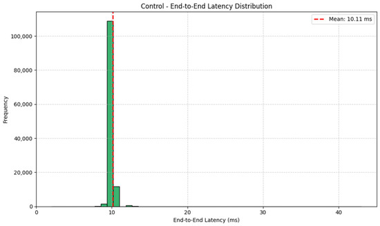
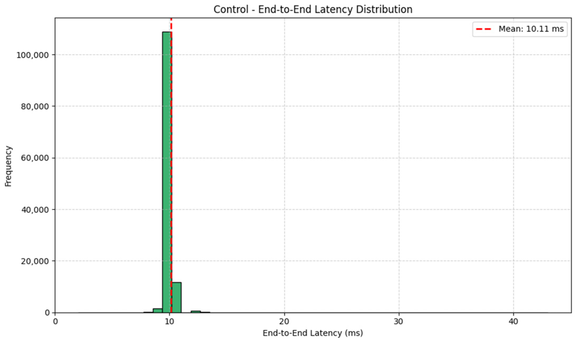
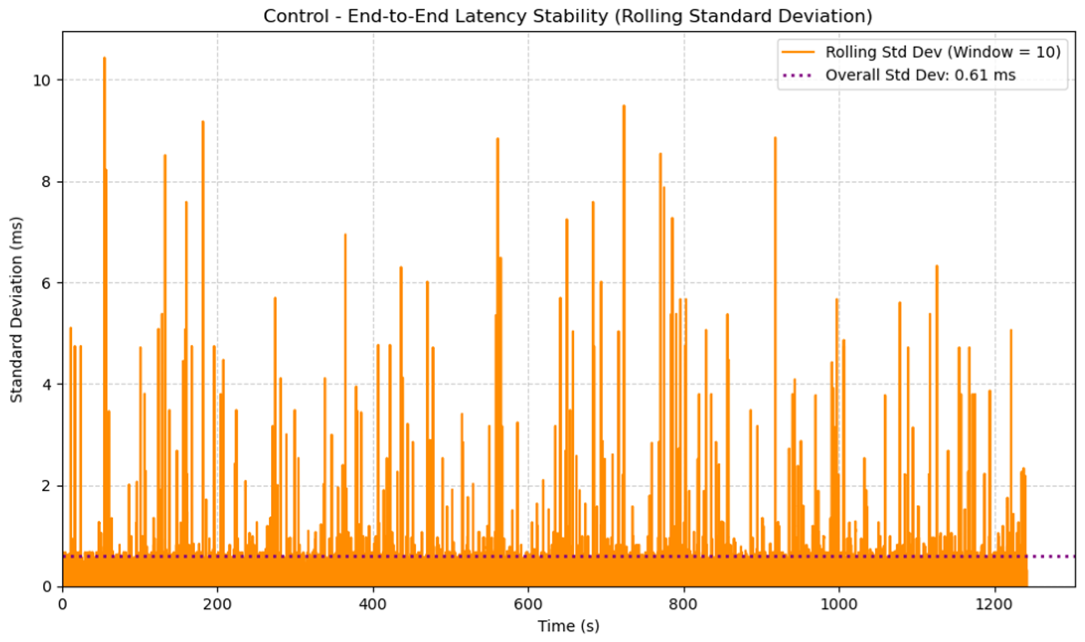
The control process’s performance is evaluated by the end-to-end latency. The sample time starts when an input is received. It is defined by the time it takes to parse the input, execute control calculations, generate a control output, and transmit it. Research done by Saez-Perez et al. on the end-to-end latency of the original Openpilot system found that the vehicle control process should have a latency of 10 ms between inputs with a standard deviation of about 2 ms [26]. Figure 6 shows that the CAN-FD controls are processed with an average processing time of 10.11 ms per cycle; 89.77% of cycles meet the target processing timing of 10 ms, 9.56% of cycles take an additional 1 ms, and 0.67% take an additional 2 ms or more. The maximum latency is 43 ms, and the minimum is 2 ms. The standard deviation is taken as a rolling average standard deviation over the last 10 data points. Figure 7 shows that it remains primarily below 1 ms with occasional spikes. The overall average standard deviation is 0.61 ms. The X2000’s control-process design performs well to meet the required speeds for real-time control, with 99.33% of cycles meeting the timing requirement and the 42 ms an outlier on initial start-up.
Figure 6.
Distribution of the end-to-end latency for each control cycle.
Figure 7.
Overall average standard deviation and rolling standard deviation of the control process’s end-to-end latency.
While the latency is highly robust, sporadic spikes were observed. The spikes suggest issues with causes such as resource contention, garbage collection, or the thermal throttling issues discussed in Section 3.5. Design methods such as shared memory help to limit the use of implicitly shared resources that can lead to resource contention [27]. Taking that methodology further by assigning specific CPU cores to the X2000’s process could further improve stability [27]. Garbage collection can also be managed more explicitly to avoid spikes. Active cooling is planned for a future design of the X2000 to address thermal performance, which is expected to improve stability by preventing thermal throttling.
3.3. Inference End-to-End Latency
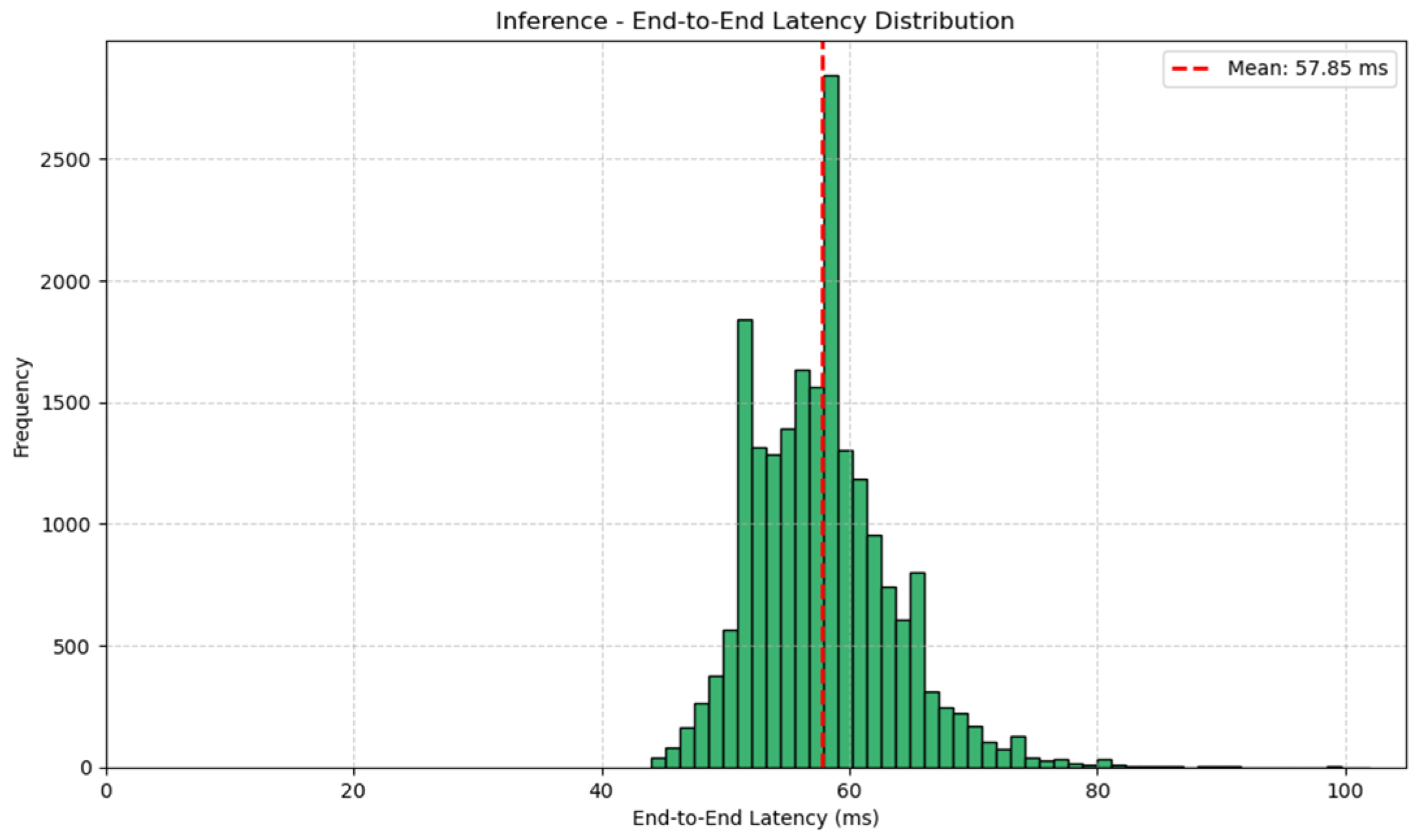
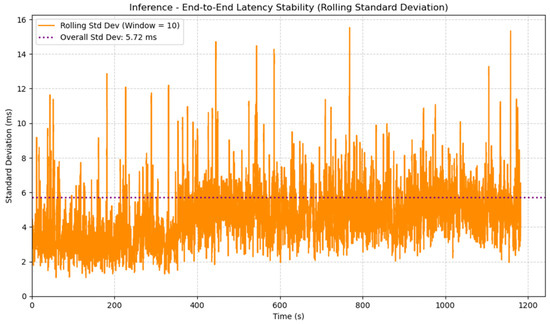
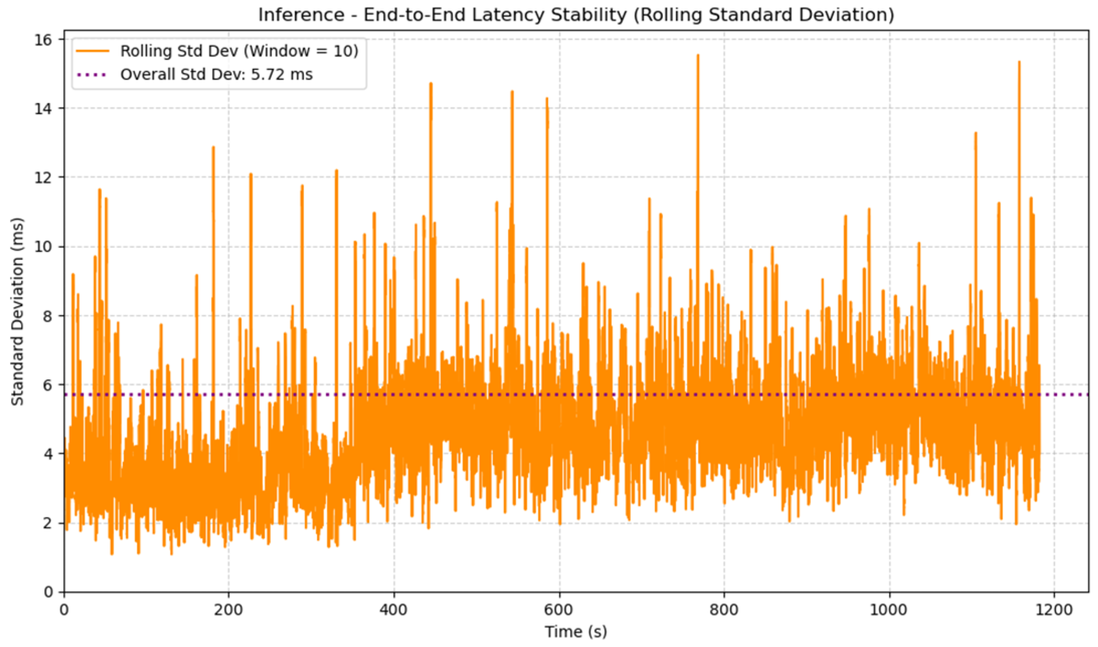
The inference process’s end-to-end latency is determined by the time taken to receive a video frame, perform inference, and write the output of the model to shared memory. Saez-Perez et al. found that the end-to-end latency for inference is expected to be 100 ms, with a standard deviation of about 7 ms [26]. Figure 8 shows that the video frames are processed with an average of 57.85 ms per frame. The highest processing time is 102 ms and the lowest is 44 ms. The distribution of processing times follows a log-normal distribution [28]. This distribution is caused by several variables such as memory access, GPU and CPU workloads, and caching contributing multiplicatively to the overall inference time [28]. Figure 9 shows the rolling standard deviation over the last 10 video frames. It ranges mostly from 2 ms to 8 ms with occasional spikes. The overall average standard deviation is 5.72 ms. Compared to the findings of Saez-Perez et al., the X2000’s inference design performs very well to achieve real-time inference, averaging a latency time 42.15% faster than required [26].
Figure 8.
Distribution of the end-to-end latency for each frame used for inference.
Figure 9.
Overall average standard deviation and rolling standard deviation of the inference process’s end-to-end latency.
Only one frame exceeded the required end-to-end latency of 100 ms at 102 ms, but spikes in the rolling standard deviation suggest some system instability that could be improved upon. The contributing factors to the log-normal distribution of the end-to-end latency mean it would not be expected that inference is as stable as control. However, the same methods discussed in Section 3.2 could be applied to the inference process as well. Explicitly defining how system resources are used wherever possible will minimize the likelihood that they conflict and cause latency spikes.
3.4. Hardware Utilization and Power Consumption
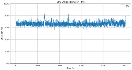
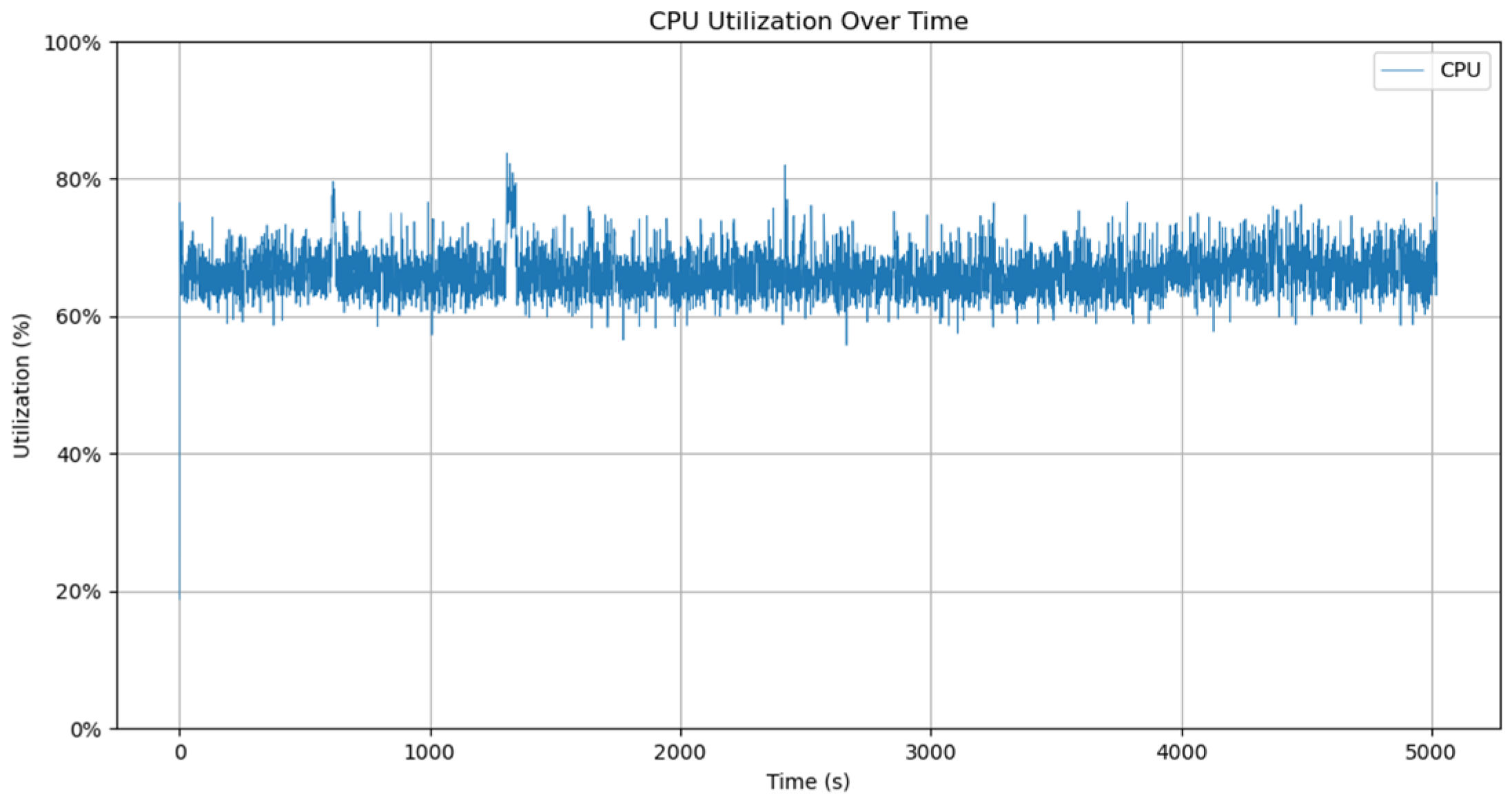
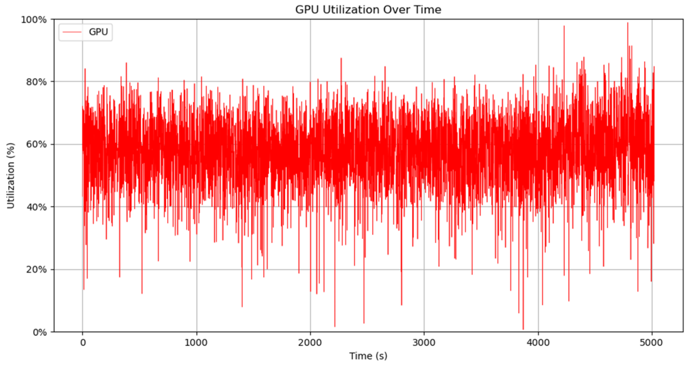
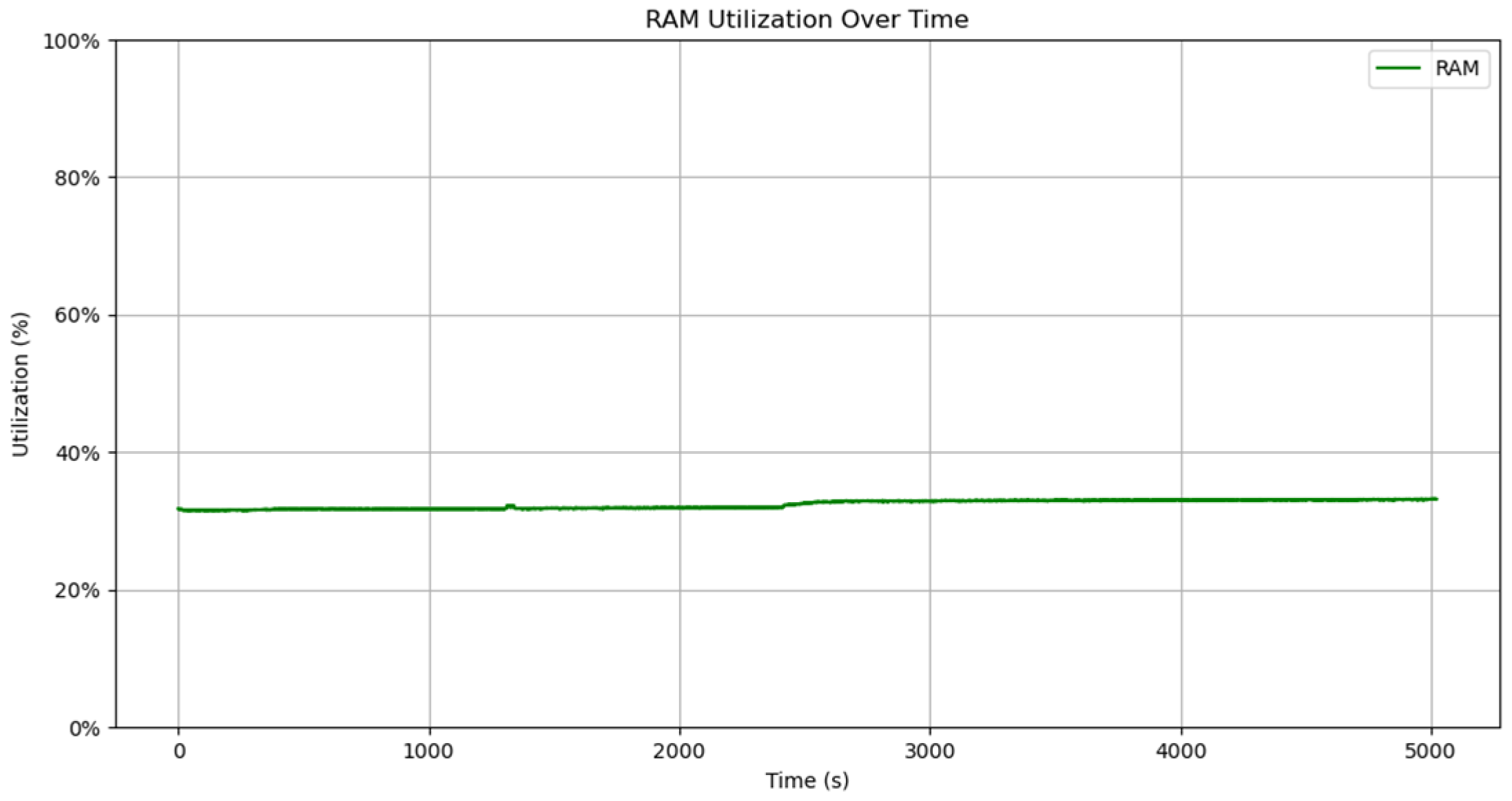
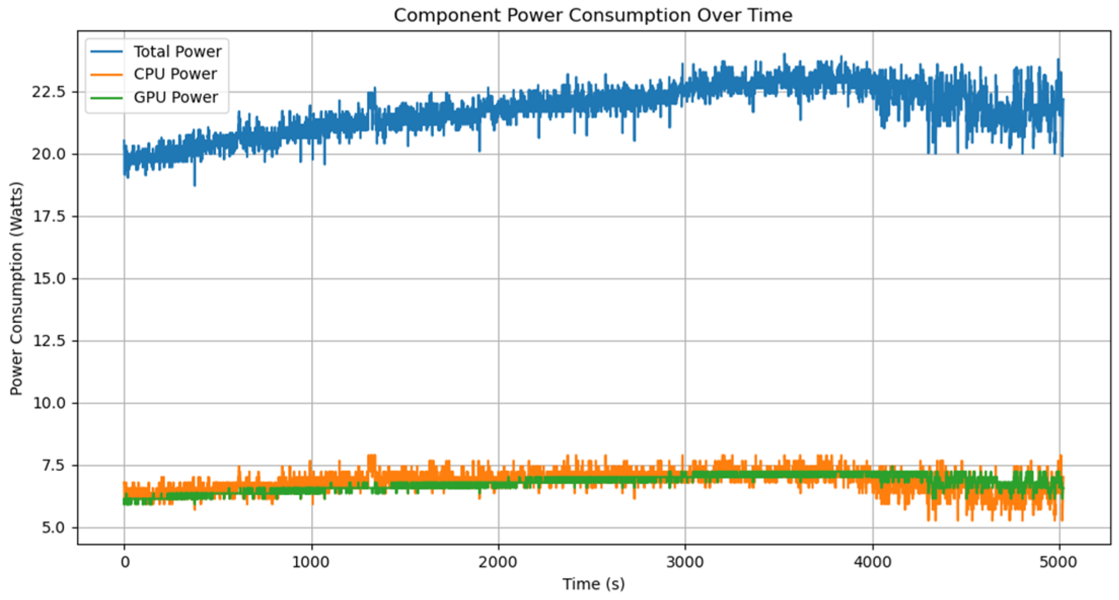
Figure 10, Figure 11, Figure 12 and Figure 13 show the behavior of the X2000’s hardware over time as it performs ADAS testing. The CPU, GPU, and RAM utilization were measured as a percentage of their total bandwidth utilized over time. The CPU, GPU, and overall power consumption were measured in Watts. The X2000 ran its main processes for ADAS testing while the data was recorded.
Figure 10.
Jetson AGX Orin CPU utilization over time while performing ADAS testing.
Figure 11.
Jetson AGX Orin GPU utilization over time while performing ADAS testing.
Figure 12.
Jetson AGX Orin RAM utilization over time while performing ADAS testing.
Figure 13.
Jetson AGX Orin power consumption over time by the CPU (orange), GPU (green), and overall device (blue) during ADAS testing.
CPU, GPU, and RAM utilization averaged 66.6%, 57.4%, and 32.4%, respectively. The CPU utilization is higher since it is responsible for running every ADAS process, while the GPU is only performing inference. Since the GPU is only under load for brief periods in the utilization measurement window when a new video frame is received, it causes high and low spikes, as well as the somewhat low average utilization [29]. RAM utilization is relatively consistent since most of the memory it requires is allocated when the main processes are initialized at startup. The specified power draw of the Jetson AGX Orin is 15 W to 40 W, so the average of 21.76 W total is good since it is at the low end of the specified range [21].
3.5. Thermal Performance
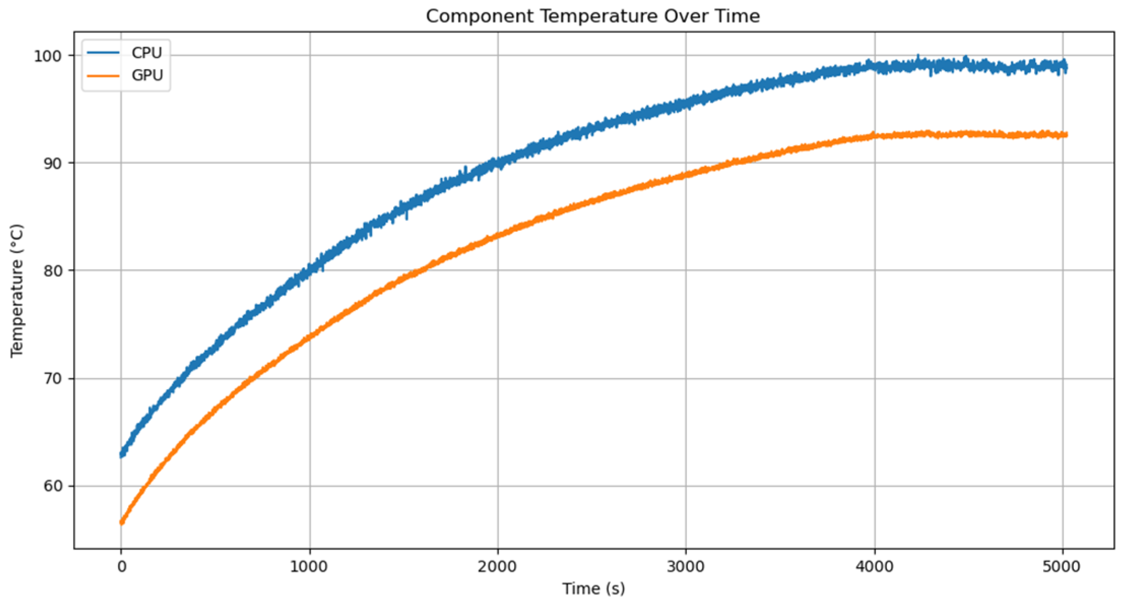
Despite the low power consumption, the thermal performance is an area in need of improvement. The chipset temperatures rise steadily at 0.43 °C per minute for both the CPU and GPU to maximums of 100 °C and 93 °C, respectively. High temperatures lead to thermal throttling, a hardware safety measure that reduces clock speeds of the CPU or GPU thereby reducing throughput [30]. The temperature curves in Figure 14 flatten when the Jetson AGX Orin begins thermal throttling.
Figure 14.
Jetson AGX Orin CPU (blue) and GPU (orange) chipset temperature over time.
Thermal throttling can negatively affect computational throughput due to a feature called dynamic voltage and frequency scaling (DVFS) [30,31]. DVFS is defined in Equation (1), where is the power consumption of the chip, is the activity factor as a percentage of transistors switching, is the chipset’s load capacitance, is the supply voltage, and is the clock frequency. The AGX Orin adjusts its CPU clock frequency, GPU clock frequency, and supply voltages to regulate and reduce its power consumption, thereby protecting it from overheating. Reduced throughput introduced by DVFS presents a risk of model performance degradation such as missed frames, late outputs, or even complete system shutdown [31].
Praveen et al. found that passive cooling using heat sinks made of copper or aluminum are effective for improving the thermal performance of hardware for ADAS applications [31]. They recommend using thermal pastes or pads to facilitate heat transfer from the chipset to the heat sink. Designing the heatsink to maximize its surface area and contact with the chipset allows the surrounding air to extract heat much more effectively [31].
This research suggests that active cooling is also necessary. Active cooling extracts heat from the system using electronics with moving parts such as fans or a water pump [31]. If passive cooling is not effective enough to prevent thermal throttling, adding fans to remove the hot air from the X2000’s heat sinks and enclosure can further improve its thermal performance [31]. There are plans for the next iteration of the X2000’s design to include active cooling via fans. In cases of extreme thermal loads, a water pump, a heat sink with liquid routing channels, and a radiator can be used to very efficiently extract heat from the system [31].
4. Discussion
This article provides a thorough evaluation of the X2000. Overall, it proves to be a capable platform for developers to leverage for rapid ADAS development. It provides an accessible, extensible, ready-to-use platform for ADAS development that simplifies the technical barriers to entry for new developers and researchers. Test results show that it can process CAN-FD inputs, build a vehicle state model, and send CAN-FD outputs required for ADAS within 1 ms of the target time at a rate of 99.33%. It can also perform inference on live video to determine vehicle steering and velocity plans at an average of 57.85 ms per frame, 42.15% below the requirement of 100 ms. The Jetson AGX Orin hardware performs well with sufficient computational capacity for additional features and capabilities in the future, though it requires active cooling when running for long periods.
The primary piece of future work for the X2000 is the implementation of real-time vehicle control by validating the safety and integrity of the CAN-FD communication pipeline on a real vehicle while driving in a wide variety a scenarios. It is essential that the driving decisions made by the X2000 can be validated in real driving scenarios for safety, accuracy, and comfort. As part of the controls validation, a method of comparing recorded vehicle data with system output predictions is planned. This has the potential to validate computer vision model accuracy and make overall ADAS development easier by enabling benchtop model testing. Thermal solutions are planned to ensure that continuous operation at a high load does not trigger thermal throttling. To further improve safety, sensor faults can be detected with methods such as attention mechanisms to improve system safety and reliability [32]. Finally, it is planned to establish structured methods of migrating the hardware and software between test vehicles and hardware platforms.
Author Contributions
Conceptualization, M.G. and G.P.; methodology, M.G.; resources, G.P.; software, M.G.; validation, M.G.; formal analysis, M.G.; investigation, M.G.; resources, M.G.; data curation, M.G.; writing—original draft preparation, M.G.; writing—review and editing, M.G. and G.P.; visualization, M.G.; supervision, G.P.; project administration, G.P. All authors have read and agreed to the published version of the manuscript.
Funding
This research received no external funding.
Data Availability Statement
Code and hardware are available by request from the authors. Data presented in this study is available to download at: https://github.com/MikeGiuliani/Analyzing-the-X2000-Advanced-Driver-Assistance-Development-Kit-Supplementary-Mats.git (accessed on 26 January 2026).
Acknowledgments
We thank Eliyahu Davis and Deepview for providing hardware and software to perform this research with. We thank the Comma.ai team and their GitHub contributors for making the software behind Openpilot open source and free to use for projects like the X2000.
Conflicts of Interest
The authors declare no conflicts of interest.
Abbreviations
The following abbreviations are used in this manuscript:
| ADAS | Advanced Driver Assistance System |
| EPAS | Electronic Power Assisted Steering |
| GMSL2 | Second-Generation Gigabit Multimedia Serial Link |
| CAN-FD | Controller Area Network Flexible Data-Rate |
| DBC | CAN Database |
| MPC | Model Predictive Control |
| BGR | Blue-Green-Red |
| RGBA | Red-Green-Blue-Alpha |
| PSCM | Power Steering Control Module |
| DVFS | Dynamic Voltage and Frequency Scaling |
References
- Nvidia DRIVE Quote Request. Available online: https://arrow.tfaforms.net/5113032 (accessed on 7 January 2026).
- DRIVE AGX Developer Kits. Available online: https://developer.nvidia.com/drive/agx#section-orin-hardware-accessories (accessed on 15 January 2026).
- Nvidia DRIVE OS Linux SDK API Reference. Available online: https://developer.nvidia.com/docs/drive/drive-os/6.0.10/public/drive-os-linux-sdk/api_reference/files.html (accessed on 8 January 2026).
- Nanz, S.; Furia, C.A. A Comparative Study of Programming Languages in Rosetta Code. In Proceedings of the 2015 IEEE/ACM 37th IEEE International Conference on Software Engineering, Florence, Italy, 16–24 May 2015; pp. 778–788. [Google Scholar] [CrossRef] [Scilit]
- Apollo. Available online: https://github.com/ApolloAuto/apollo?tab=readme-ov-file#architecture (accessed on 7 January 2026).
- Apollo Hardware Development Platform. Available online: https://developer.apollo.auto/platform/hardware.html (accessed on 15 January 2026).
- Openpilot—Open Source Advanced Driver Assistance System. Available online: https://comma.ai/openpilot (accessed on 15 January 2026).
- Openpilot process_config.py. Available online: https://github.com/commaai/openpilot/blob/master/system/manager/process_config.py (accessed on 7 January 2026).
- Openpilot service.py. Available online: https://github.com/commaai/openpilot/blob/master/cereal/services.py (accessed on 7 January 2026).
- Comma Four. Available online: https://comma.ai/shop/comma-four (accessed on 15 January 2026).
- How Openpilot Works in 2021. Available online: https://blog.comma.ai/openpilot-in-2021/ (accessed on 15 January 2026).
- Goff, M.; Hogan, G.; Hotz, G.; du Parc Locmaria, A.; Raczy, K.; Schäfer, H.; Shihadeh, A.; Zhang, W.; Yousfi, Y. Learning to Drive from a World Model. arXiv 2025, arXiv:2504.19077. [Google Scholar] [CrossRef] [Scilit]
- Openpilot. Available online: https://github.com/commaai/openpilot?tab=MIT-1-ov-file#readme (accessed on 19 August 2025).
- MIT License. Available online: https://choosealicense.com/licenses/mit/ (accessed on 19 August 2025).
- Multiprocessing—Process-Based Parallelism—Python 3.8.3rc1 Documentation. Available online: https://docs.python.org/3/library/multiprocessing.html (accessed on 7 December 2025).
- Vasu, P.K.A.; Gabriel, J.; Zhu, J.; Tuzel, O.; Ranjan, A. FastViT: A Fast Hybrid Vision Transformer using Structural Reparameterization. arXiv 2023, arXiv:2303.14189. [Google Scholar] [CrossRef] [Scilit]
- Ge, Q.; Sun, Q.; Li, S.E.; Zheng, S.; Wu, W.; Chen, X. Numerically Stable Dynamic Bicycle Model for Discrete-Time Control. In Proceedings of the 2021 IEEE Intelligent Vehicles Symposium Workshops, Nagoya, Japan, 11–12 July 2021; pp. 128–134. [Google Scholar] [CrossRef] [Scilit]
- Neural Networks in Openpilot. Available online: https://github.com/commaai/openpilot/tree/master/selfdrive/modeld/models (accessed on 26 January 2026).
- Parse_model_outputs.py. Available online: https://github.com/commaai/openpilot/blob/master/selfdrive/modeld/parse_model_outputs.py (accessed on 26 January 2026).
- Deepview Corp. AI Vehicle Computer (Devkit). Available online: https://www.deepviewai.com/_files/ugd/51ea66_afd601f136fd473eafbf55eca3c9fa07.pdf (accessed on 19 August 2025).
- Karumbunathan, L. NVIDIA Jetson AGX Orin Series a Giant Leap Forward for Robotics and Edge AI Applications Technical Brief. Available online: https://www.nvidia.com/content/dam/en-zz/Solutions/gtcf21/jetson-orin/nvidia-jetson-agx-orin-technical-brief.pdf (accessed on 19 August 2025).
- Boland, H.M.; Burgett, M.I.; Etienne, A.J.; Stwalley, R.M., III. An Overview of CAN-BUS Development, Utilization, and Future Potential in Serial Network Messaging for Off-Road Mobile Equipment. In Technology in Agriculture; IntechOpen: London, UK, 2021. [Google Scholar] [CrossRef] [Scilit]
- StereoLabs. ZED X One Camera and SDK Overview. Available online: https://www.stereolabs.com/products/zed-x-one (accessed on 19 August 2025).
- Wang, K. Gigabit Multimedia Serial Link (GMSL) Cameras as an Alternative to GigE Vision Cameras. ADI Analog Dialogue 2023, 57, 3–4. [Google Scholar]
- Openpilot Safety. Available online: https://github.com/commaai/openpilot/blob/master/docs/SAFETY.md (accessed on 19 January 2026).
- Saez-Perez, J.; Diez-Tomillo, J.; Tena-Gago, D.; Alcaraz-Calero, J.M.; Wang, Q. Design, Implementation and Validation of a Level 2 Automated Driving Vehicle Reference Architecture. Expert Syst. 2025, 42, e70050. [Google Scholar] [CrossRef] [Scilit]
- Deng, Z.; Zhang, Z.; Li, D.; Guo, Y.; Ye, Y.; Ren, Y.; Jia, N.; Hu, X. Interference-Free Operating System: A 6 Years’ Experience in Mitigating Cross-Core Interference in Linux. In Proceedings of the 2024 IEEE Real-Time Systems Symposium (RTSS), York, UK, 10–13 December 2024; pp. 308–321. [Google Scholar] [CrossRef] [Scilit]
- Limpert, E.; Stahel, W.A.; Abbt, M. Log-Normal Distributions across the Sciences: Keys and Clues. BioScience 2001, 51, 341–352. [Google Scholar] [CrossRef] [Scilit]
- Gao, Y.; He, Y.; Li, X.; Zhao, B.; Lin, H.; Liang, Y.; Zhong, J.; Zhang, H.; Wang, J.; Zeng, Y.; et al. An Empirical Study on Low GPU Utilization of Deep Learning Jobs. In Proceedings of the IEEE/ACM 46th International Conference on Software Engineering (ICSE ’24), Lisbon, Portugal, 14–20 April 2024; pp. 1–13. [Google Scholar] [CrossRef] [Scilit]
- Benoit-Cattin, T.; Velasco-Montero, D.; Fernández-Berni, J. Impact of Thermal Throttling on Long-Term Visual Inference in a CPU-Based Edge Device. Electronics 2020, 9, 2106. [Google Scholar] [CrossRef] [Scilit]
- Praveen, S.M.; Rammohan, A. Active and Passive Cooling Techniques of Graphical Processing Units in Automotive Applications—A Review. Eng. Res. Express 2024, 6, 022506. [Google Scholar] [CrossRef] [Scilit]
- Wang, S. Evaluating Cross-Building Transferability of Attention-Based Automated Fault Detection and Diagnosis for Air Handling Units: Auditorium and Hospital Case Study. Build. Environ. 2026, 287, 113889. [Google Scholar] [CrossRef] [Scilit]
Disclaimer/Publisher’s Note: The statements, opinions and data contained in all publications are solely those of the individual author(s) and contributor(s) and not of MDPI and/or the editor(s). MDPI and/or the editor(s) disclaim responsibility for any injury to people or property resulting from any ideas, methods, instructions or products referred to in the content. |
© 2026 by the authors. Licensee MDPI, Basel, Switzerland. This article is an open access article distributed under the terms and conditions of the Creative Commons Attribution (CC BY) license.