


Abstract
In this study, we present and analyze a fully optically transparent four-port ultra-wideband (UWB) antenna intended for MIMO applications. The antenna’s design is thoroughly described and extensively analyzed, focusing on current distributions across its structure, with all behavioral parameters explained. The proposed antenna design has been validated with both simulations and measurements. The antenna demonstrates excellent performance in terms of port matching, isolation, and efficiency, achieving an efficiency of 40%, which is impressive compared to optically transparent antennas in the literature. The radiation characteristics exhibit peak gains up to 4 dB with stable, symmetric, and linear polarized patterns maintained across the entire UWB range. Regarding diversity performance, the antenna displays outstanding behavior with an envelope correlation coefficient of less than 0.0016 and a diversity gain around 10 dB across the entire operating band. The antenna’s exceptional performance along with its optical transparency makes it suitable for various applications, such as medical non-invasive devices that can be easily integrated into glasses without obstructing vision. It can also be combined with solar cells for energy harvesting and communication purposes. Additionally, its structure is suitable for vehicular settings and can be seamlessly integrated into vehicle mirrors or windows.
1. Introduction
Many modern applications require multiple antenna elements to enable wireless communication between neighboring devices, such as the Internet of Things, in which the goal is to connect all devices. This renders the use of traditional antennas impractical. Additionally, there are numerous applications that demand transparency, where the “see-through” feature is essential, and the functionality depends on invisibility. Examples include smart windows in buildings and automotive systems, wearable devices, point-of-care healthcare devices, consumer electronics, and aerospace systems. Thus, transparent technology represents the future, marking a transition from the bulky, conspicuous antennas of the past to more sleek, integrated designs, eventually leading to fully transparent antennas integrated into everyday objects. In this work, we report a multifunctional device that combines these attractive features of transparency and multi-polarization operation all in a single ultra-wideband (UWB) antenna.
Transparent conductive films (TCF) are pivotal in the development of transparent antennas, offering unique optical and electrical properties that enable their integration into various applications. These films are integral to the creation of antennas that maintain both transparency and energy efficiency. Intensive research has focused on innovative materials, such as graphene [1,2], indium tin oxide (ITO) [3], silver nanowires (AgNWs) [4], conductive meshes and grids [5], and multilayers of ITO/silver/ITO [6], as promising materials owing to their flexibility, transparency, and moderate electrical conductivity. Graphene offers significant advancements in the future of transparent antennas, given its high conductivity with a low sheet resistance on the order of 80 Ω/sq and optical transparency of 90% [7]; although challenges, such as enhancing the efficiency of these antennas, must continue to be addressed for broader adoption [8]. Indium tin oxide (ITO) films are a common choice for transparent antennas owing to their high optical transparency of approximately 80%. However, they exhibit lower conductivity, and thus energy efficiency, than alternative materials. For instance, an ITO antenna in [9] achieves an efficiency of less than 30% at 2.5 GHz. Improving material processing techniques can enhance the conductivity of ITO, potentially matching that of meshed conductors. Silver nanowire films are noted for their high transmittance (85% at 550 nm) and competitive radiation efficiency (52%) [10]. Fabrication methods such as dynamic heating enhance the uniformity of these films, promising stable and efficient performance in applications such as touch panels [11]. Metal mesh (MM) films, such as copper metal mesh films, provide low sheet resistance (0.18 Ω/sq) and high transparency (85.8% at 550 nm), making them flexible and mechanically stable options for electromagnetic interference (EMI) shielding applications with a resistance increase of only 1.3% after 1000 bending cycles [12]. Micro MM films have better conductivity than TCF, while their optical transparency is comparable. However, the fabrication complexity and high cost of this technique are its drawbacks. Wired MM films are inferior in terms of transparency (>70%) because of the relatively thick metal wires obscuring part of the light. However, the antenna efficiency and conductivity of wired MM are comparable to that of nontransparent metal antennas, and fabrication is simplified by the fact that printed circuit board (PCB) techniques can be used. Thus, although graphene, ITO, silver, and metal mesh films offer the advantage of high transparency, it comes at the cost of higher sheet resistance and lower efficiency.
Innovations in material composition, such as multilayer structures and modified fabrication techniques, continue to improve the viability of transparent conductive materials for antenna applications, thereby aiming to meet the demands for transparency and efficiency in modern electronic devices. By sandwiching a thin layer of silver between two ITO layers, multilayer films of ITO/Ag/ITO achieve a balance between transparency (88% at 550 nm) and low sheet resistance (3.1 Ω/sq), leading to improved antenna efficiency. The multilayer structure is essential for broad bandwidth performance, as demonstrated by bandwidths ranging from 2.5 to 10.6 GHz [13]. Thus, these films can be ideal for adding transparency to UWB antennas.
Many multi-polarization UWB antennas have been reported [14,15,16,17,18,19] for various applications, including mobile handsets, radar systems, vehicular networks, and portable devices, owing to their ability to combine two technologies, such as UWB and MIMO. The integration of UWB technology with multiple-input multiple-output (MIMO) technology significantly enhances the capacity and performance of communication systems. UWB technology provides high data rates at low costs, whereas MIMO technology improves system efficiency by addressing limitations such as short range, fading, multipath interference, and low-power handling capabilities inherent in UWB systems. A revolutionary solution can be achieved by combining these two technologies.
The deployment of multiple antennas at both the transmitting and receiving ends of UWB systems enables the reduction in multipath fading and improvement of the channel capacity, resulting in a more robust and efficient communication system. In [14], the antenna features an annular slot and orthogonal feeding mechanisms, achieving polarization diversity from 2.8 to 11 GHz. It provides nearly omnidirectional radiation patterns and moderate gain and efficiency, making it suitable for wireless systems in which multipath fading is a concern. Sinuous antennas are another design that offers UWB radiation with polarization diversity, which is advantageous for polarimetric radar applications [15]. These antennas are planar, making them suitable for close-in sensing applications, such as ground-penetrating radar. Despite issues such as resonances affecting performance, modifications in design parameters can mitigate these resonances, enhancing performance for pulsed-sensing applications. A compact coplanar-fed antenna with polarization diversity is also available for UWB applications [16]. It features two perpendicular monopoles, offering good port isolation and orthogonal polarization operation. The design ensures an ultra-wide bandwidth and is suitable for pulse transmission, making it effective for UWB diversity applications. For vehicular networks, a tri-band/UWB polarization diversity antenna provides a flexible solution by offering both multiband and full-UWB modes. This antenna enables consistent wireless channel links in different operational states, supported by testing under various conditions, which demonstrates its efficient diversity performance [17]. Finally, a novel MIMO antenna for UWB applications was developed, which utilized a fractal circular ring structure with a modified partial ground plane. It offers a wide impedance bandwidth, pattern, and polarization diversity, with good isolation achieved without additional networks, highlighting its suitability for UWB MIMO applications [18].
In all the forementioned designs, the primary technique employed in designing UWB antennas with MIMO capabilities, such as two-port or four-port MIMO configurations, involves the strategic placement of single-antenna elements in various orientations, such as parallel or orthogonal arrangements. This approach leverages the spatial and angular separation between elements to enhance the isolation level between the ports. Additionally, isolation can be further improved by introducing specific configurations between the ports, such as the employment of a rotated strip, which alters the current distribution and increases the isolation level between the ports [19]. This method ensures efficient MIMO operation by minimizing the mutual coupling and optimizing the antenna performance. The primary limitation of the aforementioned technique for designing UWB MIMO antennas is that the resulting structures often lack symmetry about the central point. This asymmetry restricts their ability to generate circularly polarized waves, which is essential for certain applications. To address this issue, we propose a novel antenna design that exhibits both superior isolation and symmetry. This symmetrical configuration enables the antenna to achieve circular polarization easily, by feeding two orthogonal ports simultaneously with 90 degrees phase shift, making it highly suitable for UWB MIMO systems. By ensuring symmetry, the proposed design overcomes the constraints of traditional approaches and provides a more versatile solution for circularly polarized UWB MIMO antennas.
In this study, we present the design and conception of a transparent, dual-polarized, UWB antenna with diverse features that can be used for MIMO applications. The proposed antenna is superior in terms of performance and structural parameters, such as size and transparency, which unveil new applications for UWB MIMO antennas in which optical transparency is required. The remainder of this paper is organized as follows: Section 2 discusses the design of the proposed antenna; Section 3 describes the fabrication and measurement methodology; and Section 4 discusses the numerical and measured results along with the diversity performance of the antenna.
2. Antenna Design
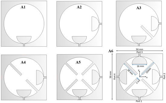
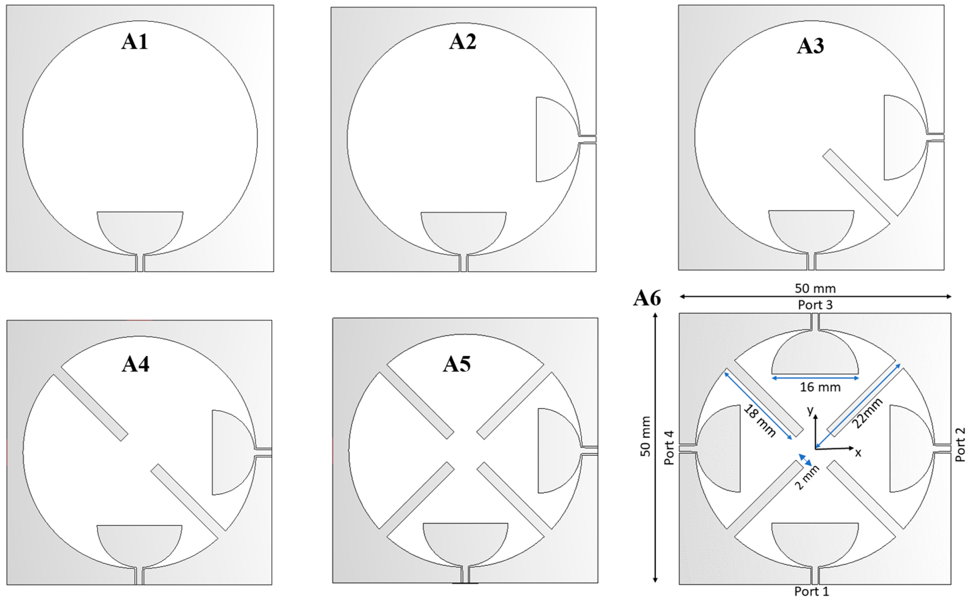
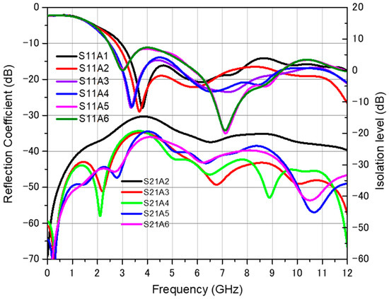
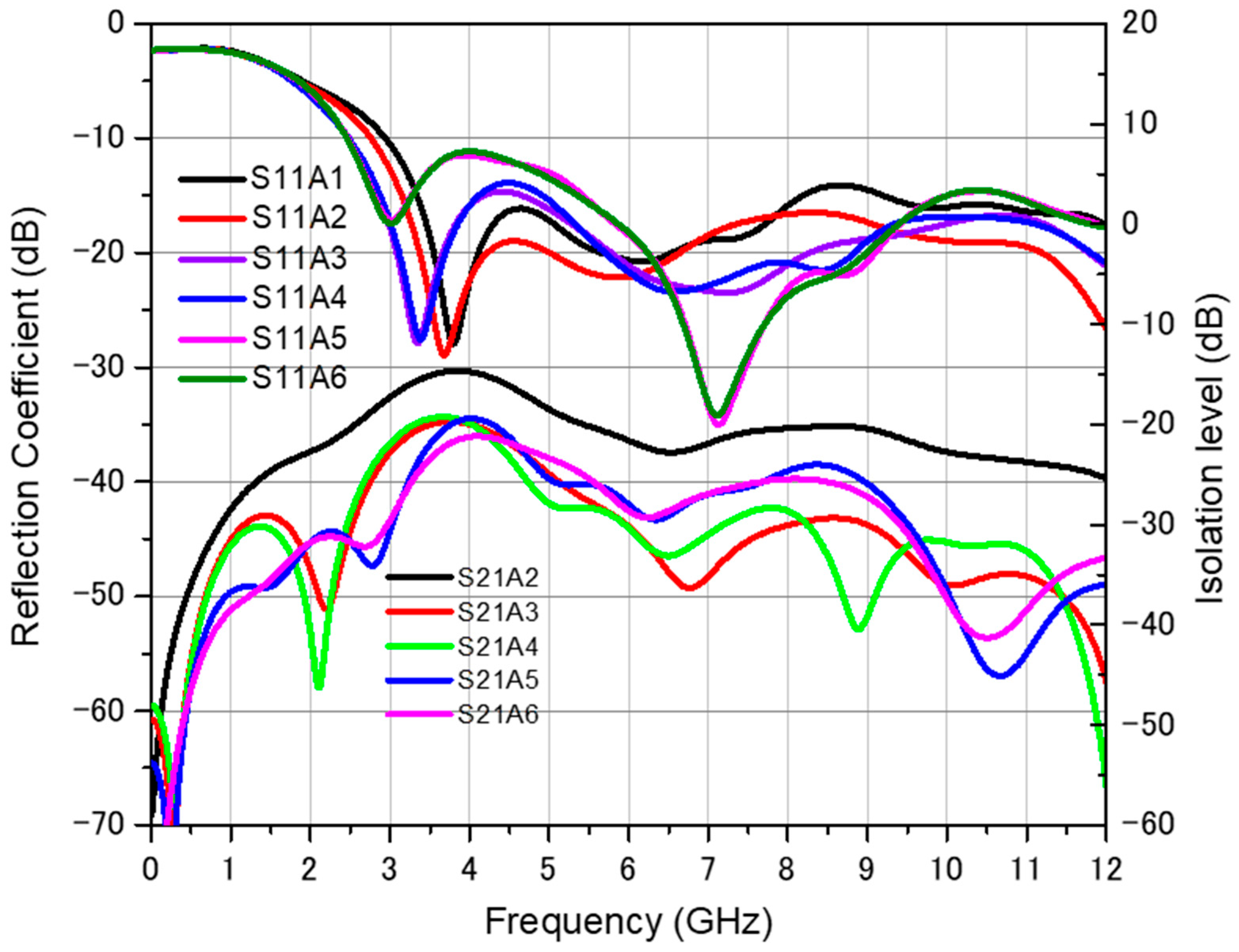
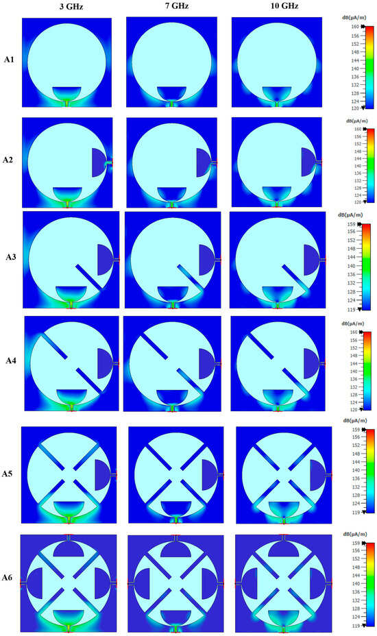
Different antenna structures were designed and analyzed based on their current distributions, and modifications were performed to address the challenges encountered. The final chosen structure of the proposed antenna was developed through a series of progressive steps, as shown in Figure 1. The simulation was performed using Computer Simulation Technology Microwave Studio (CST MWS), in which the transparent films were considered as an ohmic sheet with a sheet resistance of 3.1 Ω/m2. First, an UWB single-polarized element was designed while considering its ability to handle the desired features, such as dual polarization and multiple elements symmetrically around the center, as shown in Figure 1, and a circular slot is fed by a coplanar waveguide (CPW) line through a semi-circular patch (A1), while the circular slot, by nature, is a resonant structure, feeding it with a monopole-like structure can widen its operating bandwidth. Figure 2 shows the reflection coefficient of the first antenna (A1) which is below 10 dB over the entire band from 3 GHz to 12 GHz. This behavior is also explained by the current distributions in Figure 3(A1), where high current values can be noticed around the feed across the entire UWB band. Secondly, a similar semi-circular patch fed by a CPW line was placed in a perpendicular arrangement, as in Figure 1(A2), to excite an orthogonal mode and, consequently, achieve an orthogonal polarization. Its reflection coefficient in Figure 2 shows that antenna A2 achieves better matching over the entire operating band compared to antenna A1. In terms of isolation between the two ports, the current distributions of A2 in Figure 3 show that the excitation of port 1 creates high current values near port 2 which explains the low simulated isolation level of −14 dB at 4 GHz, as shown in Figure 2. To improve the isolation, a strip was added between the two ports in A3, resulting in a red shift in the S-parameter behavior and improvements in both matching and isolation, with an isolation better than 20 dB over the entire operating band. Figure 3(A3) also shows the ability of the inserted strip to change the current distributions across the second semi-circular disk by intercepting the current coming from the excited port. In A4, as illustrated in Figure 1, another strip was added to enhance the isolation while conserving the symmetry of the structure. Adding the strip does not affect the matching band of the antennas but rather only enhances the isolation especially at the lower frequencies, as shown in the current distributions of Figure 3(A4). To maximize the polarization purity of the antenna, two additional diagonal strips were added, as indicated in Figure 1(A5). Furthermore, to enhance the MIMO diversity characteristics, two orthogonal CPW lines ending with semi-circular patches were inserted, as shown in Figure 1(A6), establishing complete rotational symmetry. Antenna A6 shows the widest bandwidth in Figure 2, achieved from 2.5 GHz to 12 GHz, and the best isolation level achieved across the entire operating band. The current distributions over A6 (Figure 3) indicate that the three other ports are fully isolated when port 1 is excited and the current is concentrated only around the excited port and the surrounding two strips, leaving the other ports completely isolated for all frequencies investigated. Thus, the final proposed antenna has the dimensions shown in Figure 1(A6). It should be mentioned that all of the structures from A1 to A6 have the same dimensions, shown in A6, and all of the strips and semi-circular patches within the antenna have similar dimensions. The CPW lines all have a signal line width of 1.05 mm and gaps between the signal line and the coplanar ground planes of 0.3 mm, giving a 50 Ω characteristic impedance.
Figure 1.
Steps in designing the proposed UWB antenna.
Figure 2.
S-parameters of the antennas: A1, A2, A3, A4, A5, and A6.
Figure 3.
Current distributions on the antennas A1, A2, A3, A4, A5, and A6, at different frequencies 3 GHz, 7 GHz, and 10 GHz, when port 1 is excited.
3. Fabrication and Measurement Processes
3.1. Fabrication
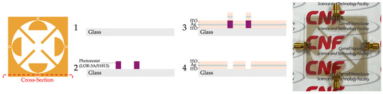
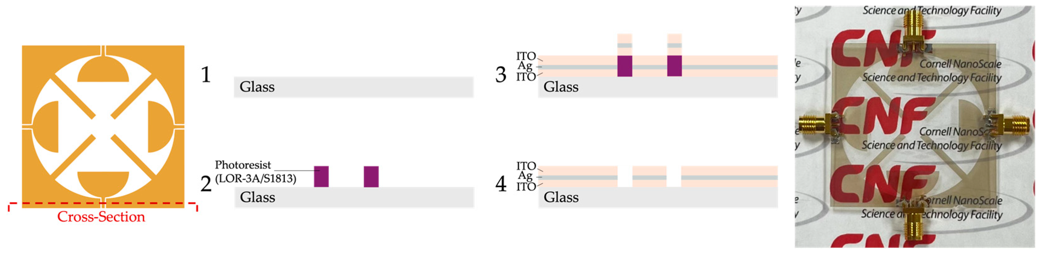
The conductive layer of the antenna is composed of a thin film of silver (Ag) inserted between two layers of indium tin oxide (ITO). The conductor stack was deposited onto a glass substrate with an approximate structure of ITO (48 nm)/Ag (17.5 nm)/ITO (42 nm)/Glass (0.7 mm), as reported in [11], where a transparency of 88% and sheet resistance of 3.1 Ω/sq were achieved. A Corning Eagle XG glass substrate (Corning, NY, USA) was used, with a relative permittivity of 5.27, loss tangent of 0.001, and thickness of 0.7 mm. The proposed structure was fabricated at the Cornell NanoScale Science and Technology Facility (CNF), Ithaca, NY, USA, and a photograph of the fabricated antenna is shown in Figure 4. The fabrication process, illustrated in Figure 4, began by cleaning the glass substrate with acetone and isopropyl alcohol, followed by pre-baking before coating with LOR-3A and S1813 photoresists in preparation for a lift-off process. The antenna design was then exposed to the substrate using a contact aligner, and the pattern was developed. 42 nm of ITO was then sputtered onto the glass substrate on one side using an indium-tin target in a Kurt J. Lesker PVD 75 sputtering tool with a partial pressure of oxygen and substrate temperature of 100 °C. The composition of the ceramic sputtering target was 90% indium/10% tin. After sputtering the ITO, a layer of Ag with a thickness of 17.5 nm was e-beam evaporated using a CHA evaporator. Then, the ITO deposition process was repeated to achieve the top layer with 48 nm thickness. Subsequently, the substrate was soaked in Microposit Remover 1165 and sonicated to lift off the photoresist and excess multilayer conductor to reveal only the desired pattern remaining on the glass substrate. The substrate was then diced using a Disco wafer saw to extract a precise square antenna piece. As a final step, 50 Ω SMA ports were connected to the antenna CPW feed lines using a conductive epoxy to prepare the antenna for measurements.
Figure 4.
Simplified fabrication process (Left) illustrating the cross-section indicated by the dashed line location on the antenna. Photograph of the fabricated prototype (Right).
3.2. Measurement
To verify that the antenna meets its design targets, we conducted two classes of measurements: (i) network-analyzer characterization to assess impedance matching and inter-port isolation, and (ii) anechoic chamber measurements to quantify radiation patterns and polarization.
- i.
- S-parameter characterization (4-port DUT)
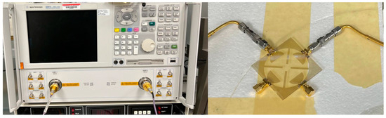
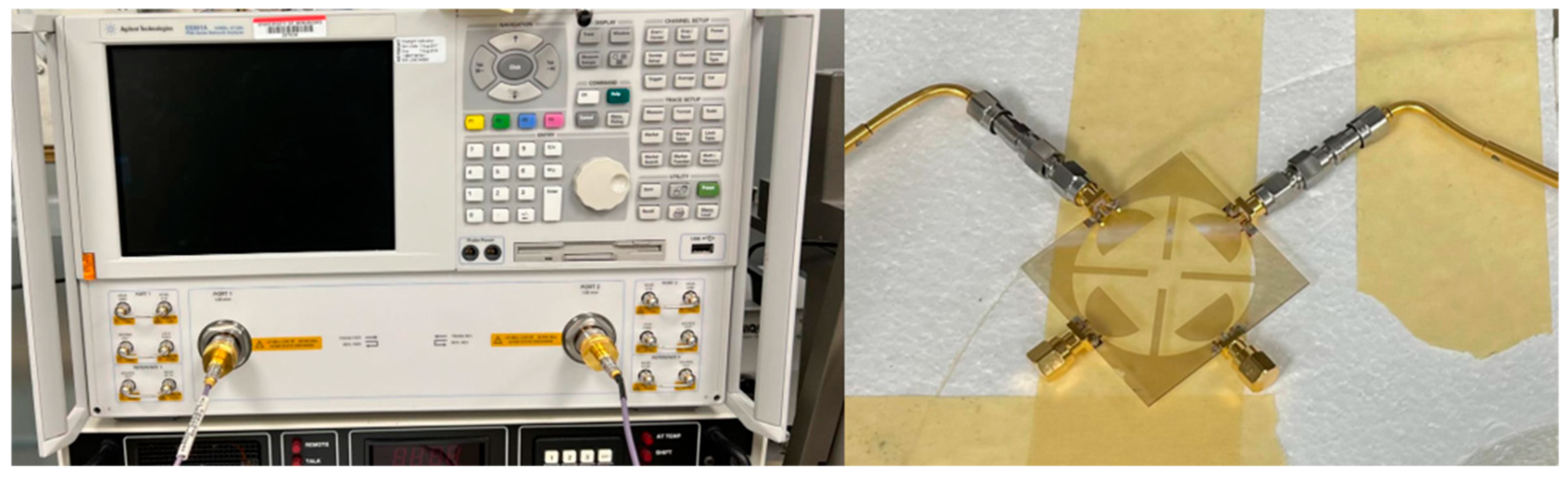
S-parameters were measured using an Agilent E8361A PNA. Each port pair was characterized while the remaining ports were terminated with precision 50 Ω loads to obtain the full 4 × 4 S-parameter matrix. For each measurement, two ports of the DUT were connected to the PNA and the other two ports were terminated as shown in Figure 5; this yielded S11, S22, S12, and S21 for that pair. The procedure was repeated across the necessary port combinations. Because the network is reciprocal (no ferrite materials) and the four ports are nominally identical and symmetric, the set {S11, S12, S13} is sufficient to reconstruct the full matrix (adjacent-port and non-adjacent couplings), where Sij = Sji. Nevertheless, measurements of Sii were performed for all four ports to account for any asymmetries introduced during fabrication. These measurements confirm the antenna’s impedance matching, resonance characteristics, and inter-port isolation.
Figure 5.
S-parameters measurement setup.
- ii.
- Radiation measurements
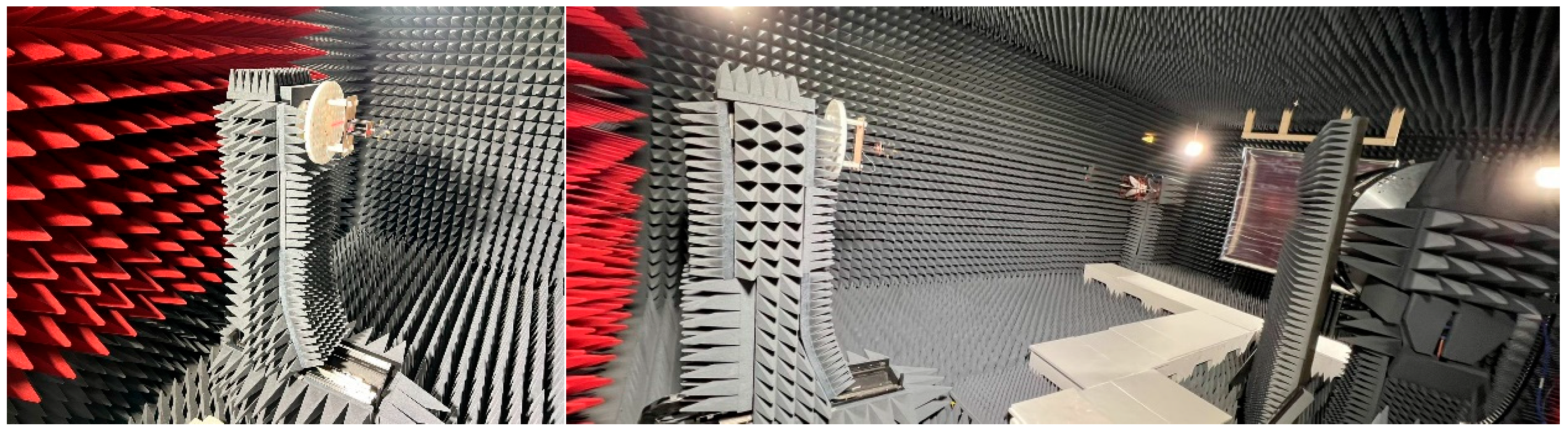
Radiation characteristics were obtained in an anechoic chamber using an azimuth-over-elevation positioner (Figure 6). Only one antenna port (Port 1) was excited during the radiation campaign; the remaining ports were terminated with precision 50 Ω loads. For the excited port, co- and cross-polarized patterns were recorded while sweeping frequency. The campaign was executed in two ranges: direct far-field (DFF) from 400 MHz to 6 GHz, and an indirect far-field method from 6 GHz to 13 GHz (near-field acquisition with NF to FF transformation). Results from the two ranges were amplitude-aligned over an overlap window and stitched in post-processing to produce continuous responses across the full band. Plane radiation patterns (co- and cross-polar) were extracted at representative frequencies.
Figure 6.
Radiation patterns measurement setup.
4. Discussion
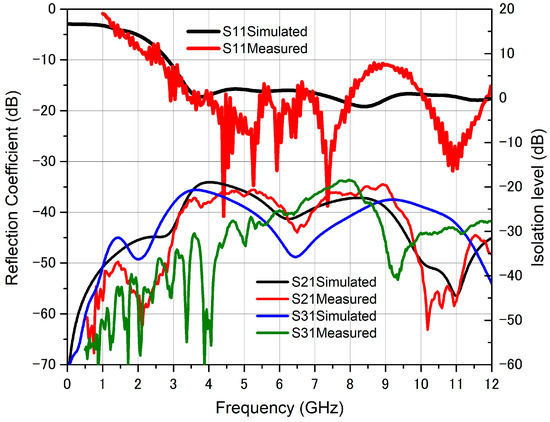
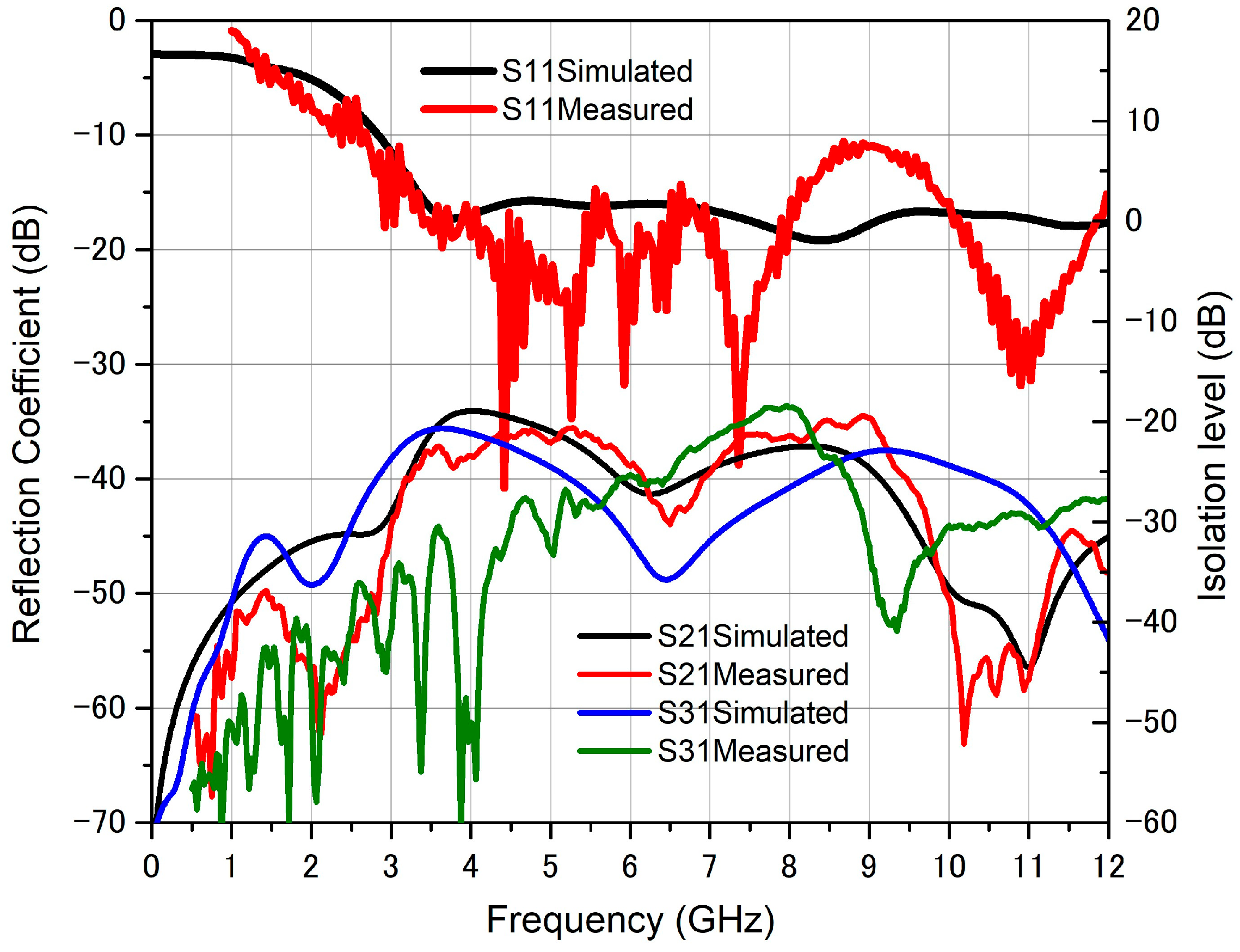
Figure 7 shows the simulated and measured reflection and transmission characteristics of the proposed antenna. Owing to the symmetry of the antenna structure, the reflection coefficients of all four ports were similar. Furthermore, the agreement between the simulated and measured results was noteworthy. Therefore, we can conclude that the antenna operates over the entire UWB band, with a good isolation level of 20 dB between adjacent ports (ports 1 and 2) and opposite ports (ports 1 and 3).
Figure 7.
Measured and simulated S-parameters of the proposed antenna.
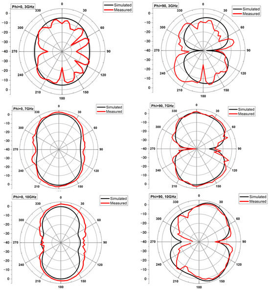
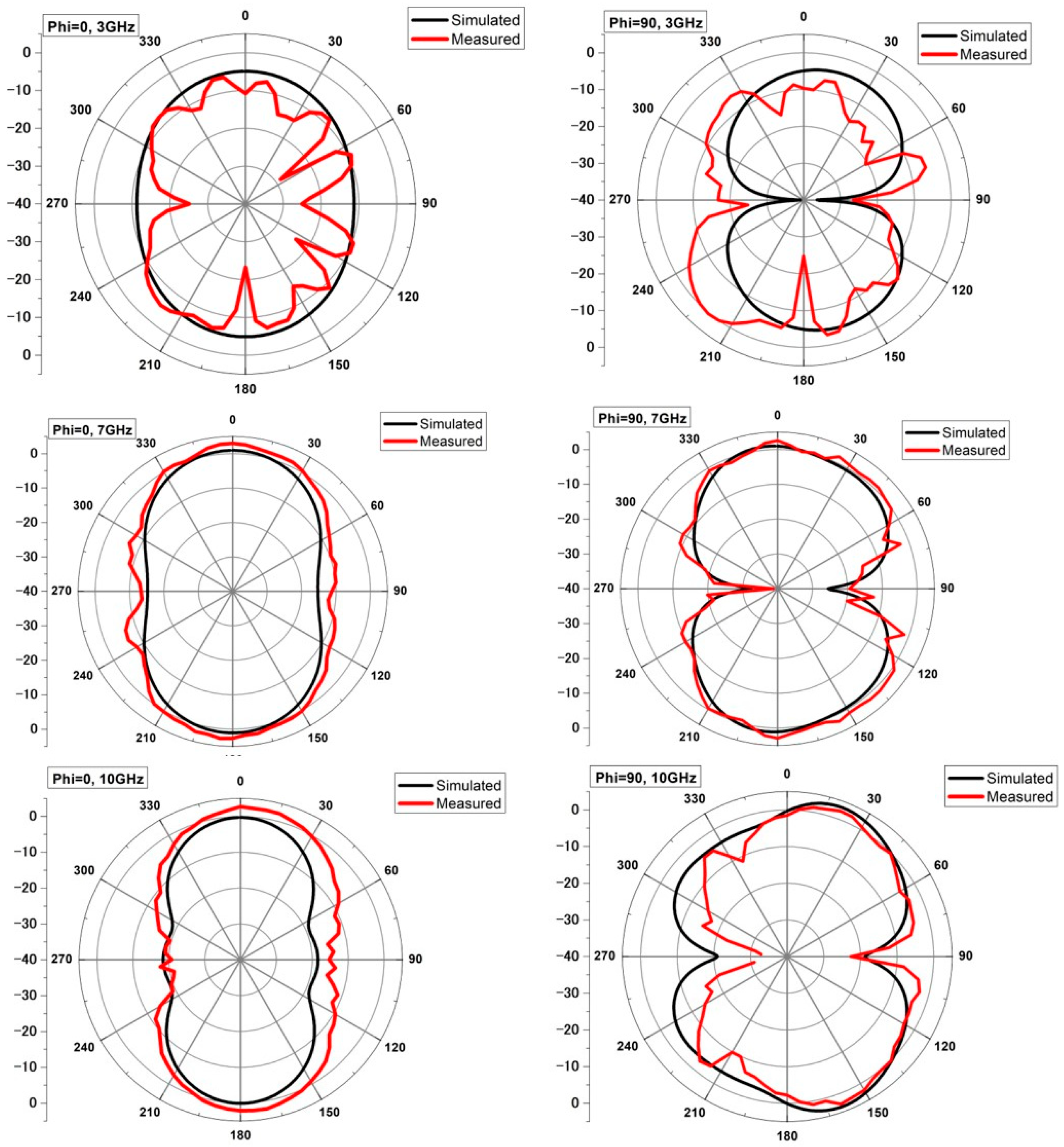
Each port of the antenna provides linearly polarized radiation patterns, as shown in Figure 8, where both the simulated and measured radiation patterns in the E-plane (xz-plane) and H-plane (yz-plane) at 3, 7, and 10 GHz are depicted. For brevity, only the radiation patterns of port 1 are shown since the radiation patterns for port 3 are similar with 180 degrees rotation, and those for ports 2 and 4 simply exhibit a rotation of 90 degrees due to their orthogonal polarization. For all radiation patterns, we notice a clear similarity over the operating band with great agreement between simulation and measurement.
Figure 8.
Simulated and measured radiation patterns of the proposed antennas in E-plane (phi = 0) and H-plane (phi = 90) at 3 GHz, 7 GHz, and 10 GHz.
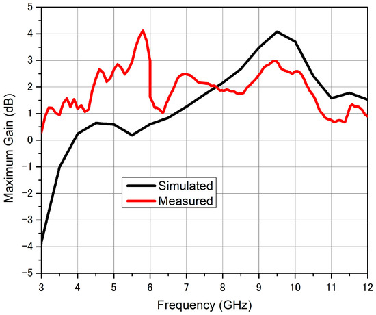
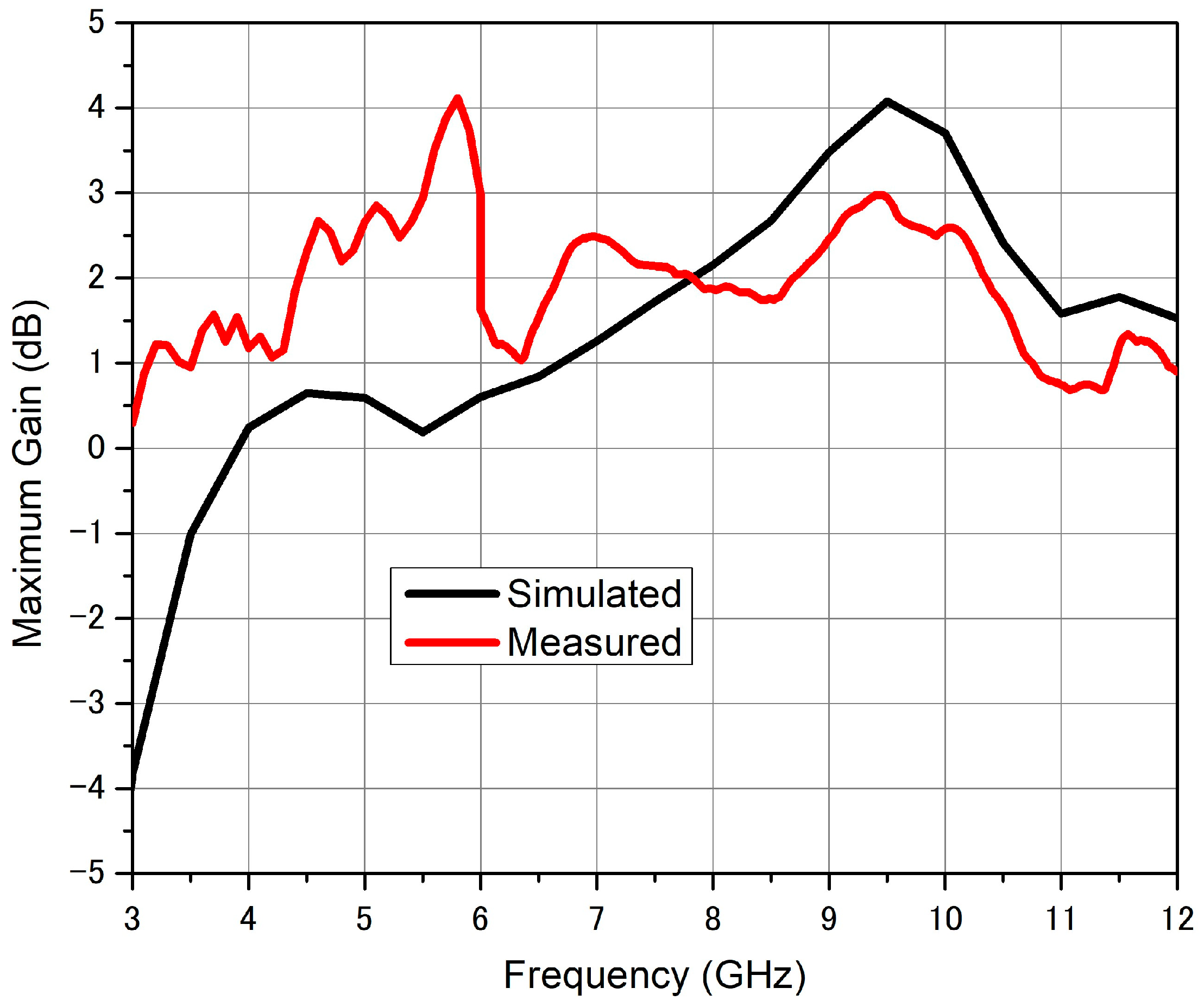
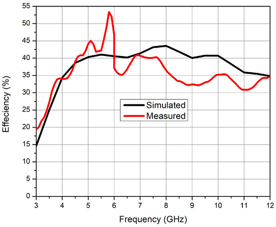
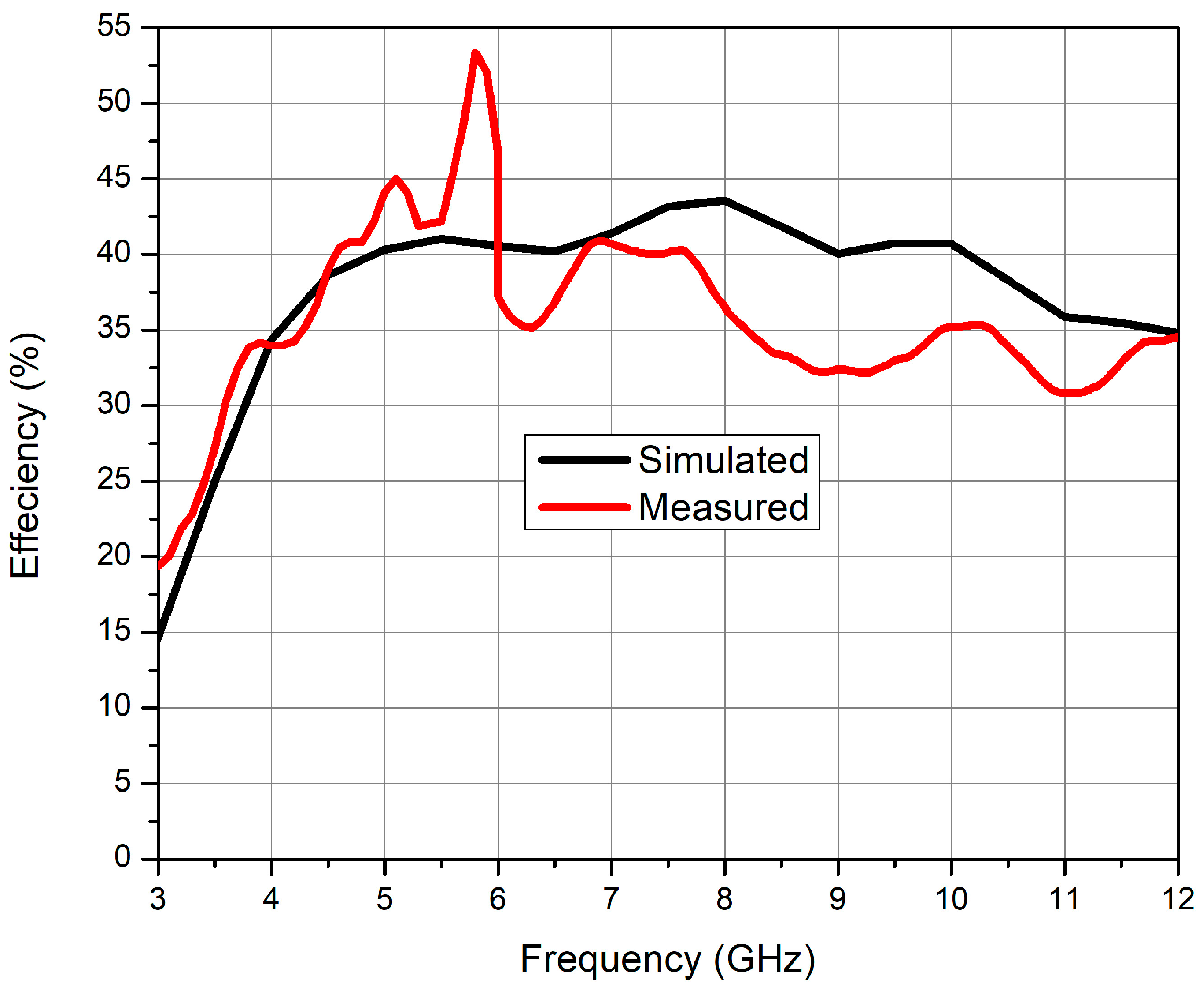
Additionally, the simulated and measured gain is shown in Figure 9, with a maximum gain of 4 dB. The efficiency is indicated in Figure 10, with an average value of 40% and maximum values of 45% and 53% at lower frequencies. The results in Figure 9 and Figure 10 show generally good agreement between the simulation and measurement, except for the 5–6 GHz range, where the measurement data deviate from the simulation owing to an artifact in the measurement procedure. Low-frequency data points were obtained using direct far-field (DFF) measurements, whereas high-frequency data points were obtained using an indirect far-field (IDF) approach based on near-field acquisition, followed by near-field to far-field transformation. The measurement artifact around 6 GHz reflects the inaccuracy of the data stitching within this transition region between the two measurement methods. The measured radiation efficiency of approximately 40% is primarily limited by the intrinsic sheet resistance of the transparent conductive multilayer (ITO/Ag/ITO), which introduces ohmic losses that are significantly higher than those of conventional metallic conductors. Although the multilayer configuration improves conductivity compared to single-layer transparent films, the effective skin depth at microwave frequencies remains comparable to the film thickness, leading to increased resistive dissipation. Additionally, the glass substrate contributes dielectric losses that further reduce efficiency. These trade-offs are inherent to optically transparent antennas, where transparency and conductivity must be balanced.
Figure 9.
Simulated and measured maximum gain of the proposed antenna.
Figure 10.
Simulated and measured efficiency of the proposed antenna.
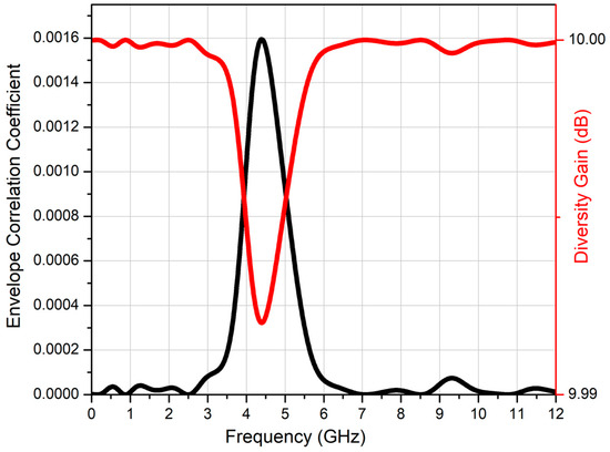
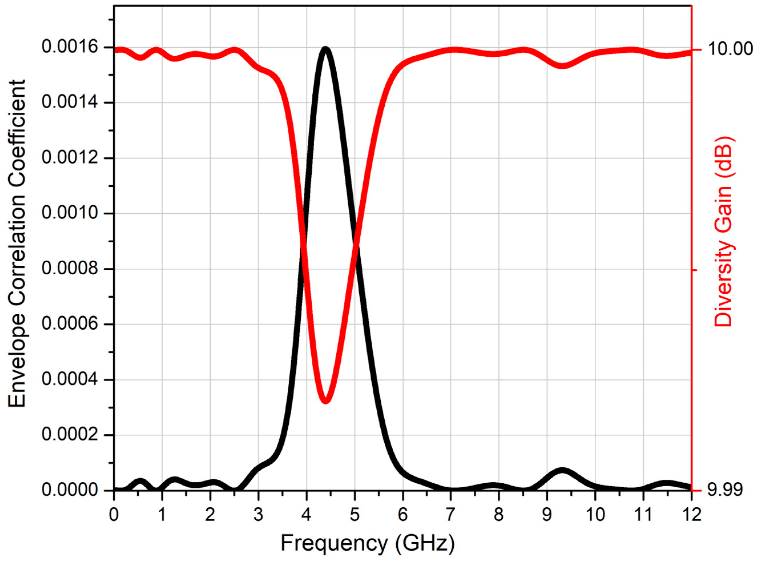
To evaluate the diversity performance of the proposed antenna and to ensure its MIMO functionality, the simulated envelope correlation coefficient (ECC), calculated using Equation (1), which indicates the interactions between the MIMO elements from their S-parameters [20] and diversity gain (DG), obtained from Equation (2), are shown in Figure 11. The value of the ECC is less than 0.0016 over the entire UWB band signifying high isolation and uncorrelated radiation patterns between any two ports of the antenna. The DG of the antenna also shows a great diversity performance with a value of 10 dB over the entire UWB band.
Figure 11.
Simulated ECC and DG for the proposed antenna.
The performance of the proposed antenna is compared with relevant state of the art designs in Table 1. The proposed antenna exhibits favorable performance compared to those in the literature in terms of its small size, high isolation, small ECC, optical transparency, and number of ports. Additionally, it provides better diversity performance than even non-transparent antennas and both better efficiency and better gain compared with other transparent antennas.
Table 1.
Comparison between the proposed antenna and the previously reported multi-polarized UWB antennas.
5. Conclusions
An ultra-wide band, dual polarization, transparent antenna with features suitable for MIMO is proposed for various applications across automotive, IOT, and medical industries, among others. The proposed antenna is particularly suited for applications where optical transparency and mechanical integration are required, such as smart vehicle glazing, wearable medical sensors, and transparent IoT nodes. Unlike conventional opaque antennas, the proposed design enables seamless integration into visually sensitive environments without compromising radiation performance or system aesthetics. The performance of the antenna has been proven through simulation and measurement results with return loss below −10 dB and an isolation level of 20 dB between ports. The proposed antenna provides high transparency, a symmetric and compact structure, dual orthogonal polarization with similar radiation patterns, and exemplary diversity characteristics with ECC less than 0.0016 and DG on the order of 10 dB over the entire UWB. Such multiport UWB antennas can significantly reduce the area consumption of antennas in wireless electronic systems and can be used even on glass surfaces to enable high data rate communications without obstructing visibility.
Author Contributions
R.Y. contributed antenna conceptualization, simulations, characterization, and writing of the manuscript. S.A. contributed radiation and S-parameter measurements. A.E.-G. contributed antenna fabrication and preliminary validation measurements. All authors have read and agreed to the published version of the manuscript.
Funding
Support for this work was provided by the U.S. National Academics US-Africa Frontiers fellowship and funded by the National Science Foundation (under Grant No. 2239066). Any opinions, findings, and conclusions or recommendations expressed in this material are those of the authors and do not necessarily reflect the views of the National Science Foundation.
Data Availability Statement
All data are contained within the article.
Acknowledgments
This work was performed in part at the Cornell NanoScale Science and Technology Facility (CNF), a member of the National Nanotechnology Coordinated Infrastructure (NNCI), which is supported by the National Science Foundation (Grant NNCI-2025233). The authors would like to express their sincere gratitude to the Research and Development Center at Prince Sattam Bin Abdulaziz University for its valuable support and assistance in conducting the antenna measurements.
Conflicts of Interest
The authors declare no conflicts of interest.
References
- Koh, S.; Kuromatsu, S.; Suga, R.; Hashimoto, O.; Kosuga, S.; Watanabe, T.; Nagata, S. Graphene transparent antennas. Carbon Rep. 2023, 2, 23–30. [Google Scholar] [CrossRef] [Scilit]
- Grande, M.; Bianco, G.V.; Laneve, D.; Capezzuto, P.; Petruzzelli, V.; Scalora, M.; Prudenzano, F.; Bruno, G.; D’ORazio, A. Optically transparent wideband CVD graphene-based microwave antennas. Appl. Phys. Lett. 2018, 112, 251103. [Google Scholar] [CrossRef] [Scilit]
- Cai, L.; Zhou, J.; Hu, H.; Xu, X.; Jiang, Z.H.; Hong, W. Indium-Tin-Oxide-Based Broadband Optically Transparent Reflectarray Antenna Using a Multilayer Hybrid Dielectric Substrate and Heterogeneous Elements. IEEE Trans. Antennas Propag. 2023, 71, 9101–9106. [Google Scholar] [CrossRef] [Scilit]
- Li, J.; Luo, J.; Liu, Y. Recent Advances in Silver Nanowire-Based Transparent Conductive Films: From Synthesis to Applications. Coatings 2025, 15, 858. [Google Scholar] [CrossRef] [Scilit]
- Fakharan, Z.; Dabirian, A. Metal grid technologies for flexible transparent conductors in large-area optoelectronics. Curr. Appl. Phys. 2021, 31, 105–121. [Google Scholar] [CrossRef] [Scilit]
- Eltresy, N.A.; Elhamid, A.E.M.A.; Elsheakh, D.M.; Elhennawy, H.M.; Abdallah, E.A. Silver Sandwiched ITO Based Transparent Antenna Array for RF Energy Harvesting in 5G Mid-Range of Frequencies. IEEE Access 2021, 9, 49476–49486. [Google Scholar] [CrossRef] [Scilit]
- Kosuga, S.; Nagata, S.; Kuromatsu, S.; Suga, R.; Watanabe, T.; Hashimoto, O.; Koh, S. Optically transparent antenna based on carrier-doped three-layer stacked graphene. AIP Adv. 2021, 11, 035136. [Google Scholar] [CrossRef] [Scilit]
- Zhang, H.; Zhang, Y.; Shao, L.; Liu, G.; Zhou, Z.; Shi, H.; Piao, M. Transparent antenna with RCS tunability based on graphene and metasurface in S band. Appl. Phys. Lett. 2024, 125, 103501. [Google Scholar] [CrossRef] [Scilit]
- Yasin, T.; Baktur, R.; Furse, C. A comparative study on two types of transparent patch antennas. In Proceedings of the 2011 XXXth URSI General Assembly and Scientific Symposium, Istanbul, Turkey, 13–20 August 2011; pp. 1–4. [Google Scholar] [CrossRef] [Scilit]
- Goliya, Y.; Rivadeneyra, A.; Salmeron, J.F.; Albrecht, A.; Mock, J.; Haider, M.; Russer, J.; Cruz, B.; Eschlwech, P.; Biebl, E.; et al. Next Generation Antennas Based on Screen-Printed and Transparent Silver Nanowire Films. Adv. Opt. Mater. 2019, 7, 1900995. [Google Scholar] [CrossRef] [Scilit]
- Jia, Y.; Li, S.; Chen, C.; Ji, S.; Ye, C.; Jia, D. Silver Nanowire Transparent Conductive Films with High Uniformity Fabricated via a Dynamic Heating Method. ACS Appl. Mater. Interfaces 2016, 8, 9865–9871. [Google Scholar] [CrossRef] [Scilit]
- Chen, Z.; Yang, S.; Huang, J.; Gu, Y.; Huang, W.; Liu, S.; Lin, Z.; Zeng, Z.; Hu, Y.; Chen, Z.; et al. Flexible, Transparent and Conductive Metal Mesh Films with Ultra-High FoM for Stretchable Heating and Electromagnetic Interference Shielding. Nano-Micro Lett. 2024, 16, 92. [Google Scholar] [CrossRef] [Scilit] [PubMed]
- Kim, J.-W.; Cho, I.-N.; Jung, K.-J.; Kim, K.-S.; Yu, J.-W.; Oh, J.-I. Efficiency-Improved UWB Transparent Antennas Using ITO/Ag/ITO Multilayer Electrode Films. IEEE Access 2021, 9, 165385–165393. [Google Scholar] [CrossRef] [Scilit]
- Chacko, B.P.; Augustin, G.; Denidni, T.A. Uniplanar Slot Antenna for Ultrawideband Polarization-Diversity Applications. IEEE Antennas Wirel. Propag. Lett. 2013, 12, 88–91. [Google Scholar] [CrossRef] [Scilit]
- Crocker, D.A.; Scott, W.R. On the Design of Sinuous Antennas for UWB Radar Applications. IEEE Antennas Wirel. Propag. Lett. 2019, 18, 1347–1351. [Google Scholar] [CrossRef] [Scilit]
- Koohestani, M.; Skrivervik, A.K.; Moreira, A.A. A Novel Compact CPW-Fed Polarization Diversity Ultrawideband Antenna. IEEE Antennas Wirel. Propag. Lett. 2014, 13, 563–566. [Google Scholar] [CrossRef] [Scilit]
- Alsath, M.G.N.; Arun, H.; Selvam, Y.P.; Kanagasabai, M.; Kingsly, S.; Subbaraj, S.; Sivasamy, R.; Palaniswamy, S.K.; Natarajan, R. An Integrated Tri-Band/UWB Polarization Diversity Antenna for Vehicular Networks. IEEE Trans. Veh. Technol. 2018, 67, 5613–5620. [Google Scholar] [CrossRef]
- Alharbi, A.G.; Rafique, U.; Ullah, S.; Khan, S.; Abbas, S.M.; Ali, E.M.; Alibakhshikenari, M.; Dalarsson, M. Novel MIMO Antenna System for Ultra-Wideband Applications. Appl. Sci. 2022, 12, 3684. [Google Scholar] [CrossRef] [Scilit]
- Parchin, N.O.; Basherlou, H.J.; Al-Yasir, Y.I.A.; Abdulkhaleq, A.M.; Abd-Alhameed, R.A. Ultra-Wideband Diversity MIMO Antenna System for Future Mobile Handsets. Sensors 2020, 20, 2371. [Google Scholar] [CrossRef] [Scilit]
- Suresh, A.C.; Reddy, T.S.; Madhav, B.T.P.; Alshathri, S.; El-Shafai, W.; Das, S.; Sorathiya, V. A Novel Design of Spike-Shaped Miniaturized 4 × 4 MIMO Antenna for Wireless UWB Network Applications Using Characteristic Mode Analysis. Micromachines 2023, 14, 612. [Google Scholar] [CrossRef] [Scilit] [PubMed]
- Govindan, T.; Palaniswamy, S.K.; Kanahasabai, M.; Kumar, S. Design and Analysis of UWB MIMO Antenna for Smart Fabric Communications. Int. J. Antennas Propag. 2022, 2022, 5307430. [Google Scholar] [CrossRef] [Scilit]
- Alfakhri, A. Dual polarization and mutual coupling improvement of UWB MIMO antenna with cross shape decoupling structure. e-Prime Adv. Electr. Eng. Electron. Energy 2023, 4, 100–130. [Google Scholar] [CrossRef] [Scilit]
- Rakluea, P.; Wongsin, N.; Mahatthanajatuphat, C.; Aroonmitr, P.; Jangjing, T.; Rakluea, C.; Chanwattanapong, W.; Chudpooti, N. Flexible Thin Film-Based Triple Port UWB MIMO Antenna With Modified Ground Plane for UWB, WLAN, WiMAX, WPAN and 5G Applications. IEEE Access 2023, 11, 107031–107048. [Google Scholar] [CrossRef] [Scilit]
- Potti, D.; Tusharika, Y.; Alsath, M.G.N.; Kirubaveni, S.; Kanagasabai, M.; Sankararajan, R.; Narendhiran, S.; Bhargav, P.B. A Novel Optically Transparent UWB Antenna for Automotive MIMO Communications. IEEE Trans. Antennas Propag. 2021, 69, 3821–3828. [Google Scholar] [CrossRef] [Scilit]
- Yao, Y.; Shao, Y.; Zhang, J.; Zhang, J. A Transparent Antenna Using Metal Mesh for UWB MIMO Applications. IEEE Trans. Antennas Propag. 2023, 71, 3836–3844. [Google Scholar] [CrossRef] [Scilit]
- Arpan, D.; Palandoken, M.; Kulkarni, J.; Byun, G.; Nguyen, T.K. Wideband flexible/transparent connected-ground MIMO antennas for sub-6 GHz 5G and WLAN applications. IEEE Access 2021, 9, 147003–147011. [Google Scholar] [CrossRef] [Scilit]
- Yao, Y.; Shao, Y.; Zhang, J.; Zhang, J. UWB MIMO optical transparent antenna based on ITO film. IEICE Electron. Express 2023, 20, 20230022. [Google Scholar] [CrossRef] [Scilit]


Disclaimer/Publisher’s Note: The statements, opinions and data contained in all publications are solely those of the individual author(s) and contributor(s) and not of MDPI and/or the editor(s). MDPI and/or the editor(s) disclaim responsibility for any injury to people or property resulting from any ideas, methods, instructions or products referred to in the content. |
© 2026 by the authors. Licensee MDPI, Basel, Switzerland. This article is an open access article distributed under the terms and conditions of the Creative Commons Attribution (CC BY) license.