


Abstract
5G communication is characterized by a broad bandwidth, enabling a peak information transmission capacity of up to 20 Gbit/s under ideal conditions. In order to achieve this goal, millimeter-wave antennas are utilized. However, classical parabolic reflectors often suffer from limited effective aperture due to manufacturing constraints, which restrict their achievable gain. To enhance gain while maintaining a compact form factor, in this paper, a dual-reflector antenna is adopted. By tilting the main radiation direction of the feed antenna in the Cassegrain configuration, the sub-reflector and main reflector are truncated with reference to the ray-tracing coverage area. This design can not only suppress the blockage effect existing in traditional Cassegrain antennas but also improve the effective radiation performance of the main reflector. Moreover, since substrate-integrated waveguide (SIW) is well suited for millimeter-wave applications, a planar SIW-fed Yagi-Uda antenna array is synthesized as the feed. The fabrication of such a dual reflector is inherently complex. However, the combination of 3D printing and metal coating using vacuum deposition creates a simple and efficient manufacturing process. Experimental results demonstrate that the proposed antenna achieves a gain of 27 dBi over 57–64 GHz with a stable pointing of the main beam direction across the operating band.
1. Introduction
With the rapid development of broadband technology, there is a huge potential market demand for wireless communication at data rates of 1 Gbit/s and beyond. 5G mobile communication is expected to meet this demand by providing peak data rates up to 20 Gbit/s and sub-millisecond latency. A straightforward way to achieve a high data rate is to shift the operating frequencies into the millimeter-wave range. Currently, the 60 GHz millimeter wave is particularly well-suited, as it offers significantly wider available bandwidth and thus higher transmission capacity than lower frequency schemes such as 28 GHz [1]. Concerning the antennas working at 60 GHz, they must satisfy stringent specifications such as high gain, low loss, wide bandwidth, ease of integration, and low cost.
Although both antennas and active circuits can be co-integrated in silicon-based on-chip systems, which are prevalent for millimeter-wave applications, these schemes suffer from excessive substrate loss at 60 GHz. By employing through-silicon-via (TSV) technology [1], the popular on-chip antennas, such as Microstrip antennas [2] and substrate-integrated waveguide (SIW) antennas [3,4,5,6], are promising candidates to meet the required specifications. However, array synthesis is necessary. Unfortunately, the radiation efficiency of the planar arrays at millimeter-wave specifications typically suffers from high loss and low radiation efficiency [7]. In consequence, the reflector antenna turns out to be a more attractive alternative. For example, in [8], a low-profile reflector is realized by hollowing out concentric circles of different radii in a multilayer substrate, fed by planar dipole antennas; the resulting cross-section approximates a paraboloid and produces a directional beam. However, the bandwidth of such a low-profile design is limited to only 4 GHz. To achieve a broadband design together with high gain, a shaped dual-reflector antenna is adopted in this work. Conventional metallic reflectors are not only difficult to fabricate with high precision but are also too heavy to be applied in many millimeter-wave applications. In contrast, the reflector can be readily fabricated by 3D printing using plastic powder, followed by vacuum deposition. This approach can achieve geometric accuracy within 0.1 mm and reduce the weight by approximately 80% compared with a conventional metallic reflector.
One critical component of the reflector antenna is the feed antenna, which usually uses a waveguide interface and hinders seamless integration with active circuits [9,10,11]. To overcome this limitation, a planar microstrip Yagi-Uda antenna is used as the feed [12]. Although this design enables seamless integration with active modules, its reported radiation gain is only 20 dBi, which needs further improvement. Inspired by [13], a subreflector could be employed to expand the feed beam, thereby improving the aperture efficiency of the main reflector. In this paper, a high-gain compact offset Cassegrain antenna fabricated by 3D printing is proposed for millimeter-wave applications. Instead of using complex-shaped surfaces, this work focuses on the efficient integration of a planar SIW-fed Yagi-Uda with a standard offset dual-reflector configuration. The key feature of the design is the tilted arrangement of the feed antenna, which places the sub-reflector and feed antenna outside the aperture of the main reflector to eliminate blockage while maintaining a low profile. The antenna system comprises the planar feed antenna, a parabolic main reflector, and a hyperbolic sub-reflector; all reflectors are realized through cost-effective 3D printing and metal coating. The remainder of the paper is organized as follows: Section 2 details the design principles of the feed antenna and the offset reflector system. The simulated and experimental results are presented in Section 3, followed by conclusions in Section 4.
2. Antenna Design
2.1. Feed Antenna Design
The Yagi-Uda antenna is a type of end-fire array that can achieve high gain, broad bandwidth, and low cross-polarization levels. In particular, the planar Yagi-Uda antenna offers a low profile and ease of integration with planar circuits, making it highly attractive for millimeter-wave applications [14]. Therefore, in this design, the planar SIW-fed Yagi-Uda antenna is selected as the feed antenna for the reflector. Compared with microstrip-fed counterparts, the SIW-fed configuration provides superior electromagnetic isolation, which is critical for reducing unwanted coupling in a compact printed circuit board (PCB) integration. In the proposed structure, the reflector is realized by an extended ground line printed on the PCB, while the driven element employs a planar dipole printed on both sides of the PCB. The planar dipole and the microstrip feed line are connected through an SIW section, which serves as a balanced-to-unbalanced converter (balun).
The design of the proposed feed antenna consists of three steps. Firstly, the printed Yagi-Uda array is synthesized using design tables for maximum directivity in free space, and then the resulting dimensions are scaled to account for the dielectric loading effect of the substrate [15]. Secondly, the SIW feeding structure can be designed independently. This waveguide-like structure supports the dominant TE10 mode and higher-order Ten0 modes, which is similar to those of rectangular metallic waveguides, provided that the metallically coated vias are closely spaced such that the leaky radiation can be ignored. Owing to this similarity, empirical formulae correlating the physical SIW dimensions, i.e., via diameter and pitch, to the equivalent width of a substrate-loaded rectangular waveguide have been well-established. These relations enable a straightforward determination of the SIW geometry [16,17,18]. Finally, in the transition region between the SIW and the Yagi-Uda array, an array of slots is etched on the ground plane to suppress surface waves, thereby improving the front-to-back ratio.
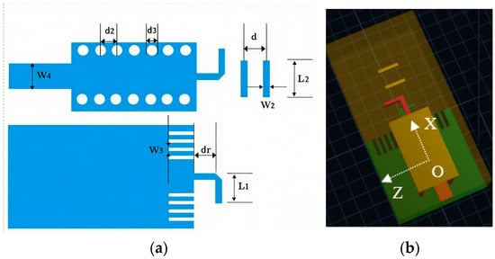
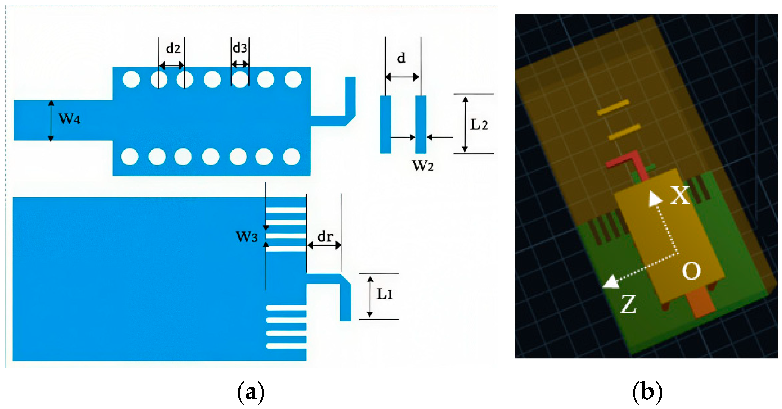
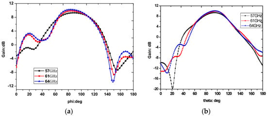
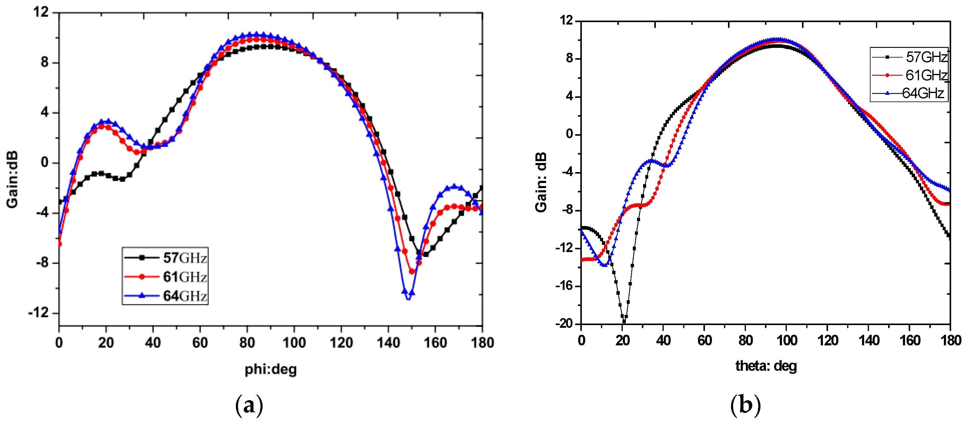
The initial design is fine-tuned using a full-wave simulator, Ansys HFSS 2023 R1. The optimized geometric parameters are listed in Table 1, and the layout of the two planar directors is illustrated in Figure 1. The simulated radiation patterns in the E-plane (XOZ) and H-plane at three representative frequencies (57, 61, and 64 GHz) are presented in Figure 2, while the simulated S-parameters are presented in Section 3. As can be observed, the proposed SIW-fed Yagi-Uda antenna achieves satisfactory radiation gain and impedance bandwidth over the frequencies of interest, confirming its suitability as a feed for the reflector system.
Table 1.
The geometry parameters of the Yagi Antenna.
Figure 1.
Geometry of the proposed SIW-fed Yagi-Uda antenna (a) and its 3D view (b).
Figure 2.
E-plane (a) and H-plane (b) radiation patterns of the proposed SIW-fed Yagi-Uda antenna.
2.2. Dual Reflector Design
In this design, the parabolic reflector is adopted as the primary configuration, owing to its widespread use and well-understood performance. To mitigate the aperture blockage caused by the feed and its supporting structures, an offset of the feed antenna is employed. The geometry of the offset parabolic reflector is depicted in Figure 3. The focal length and aperture diameter of the reflector can be determined based on the beam width and the phase-center location of the feed antenna, following the design guidelines presented in [19] and previously applied in our earlier work [12]. With this design, a radiation gain of approximately 20 dBi is achieved.
Figure 3.
An offset parabolic reflector.
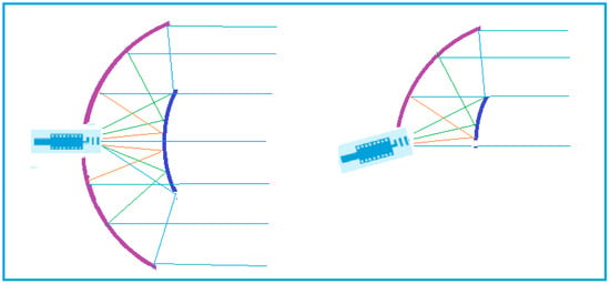
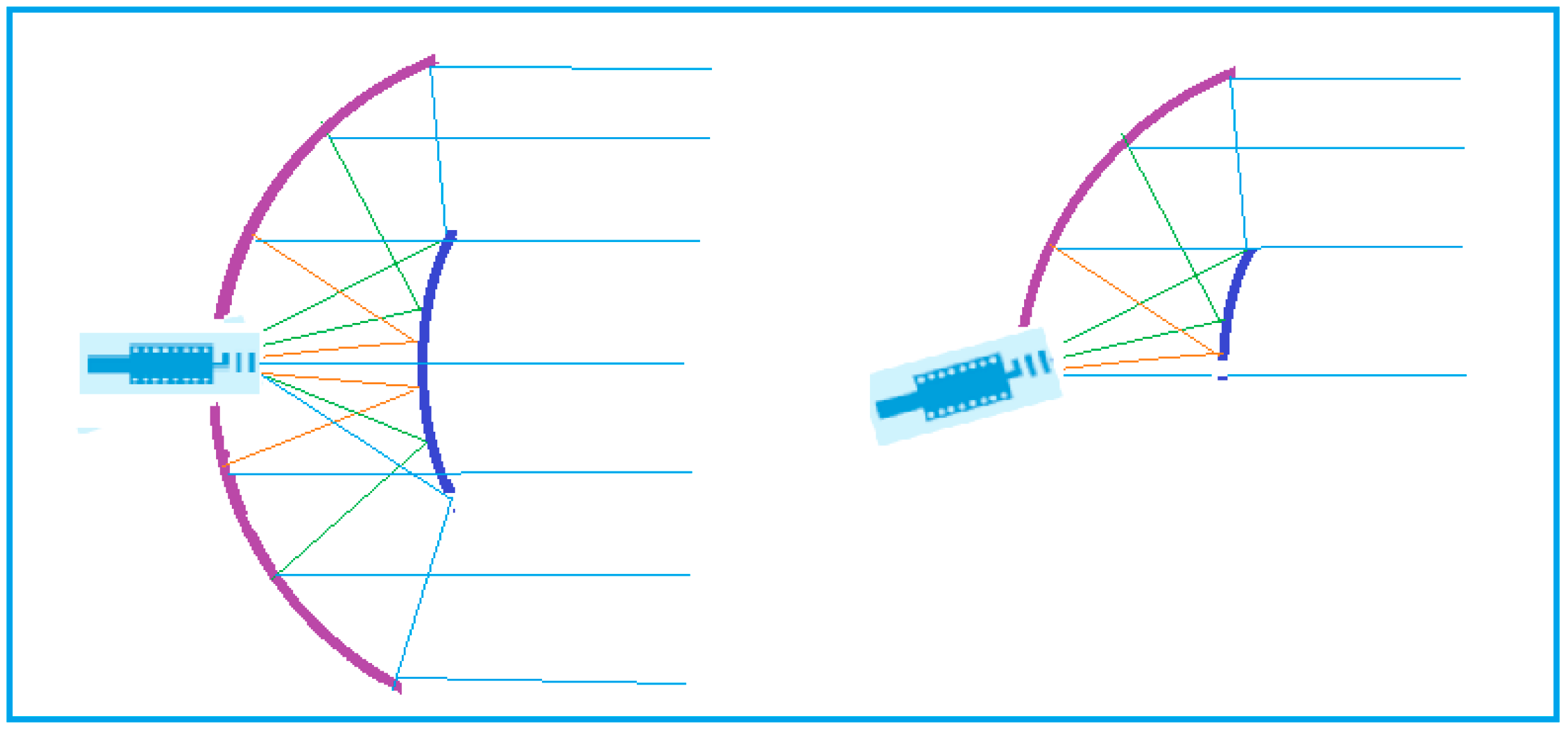
If a further increased gain is required, according to the aperture field theory, it suggests that enlarging the effective aperture would be a direct approach. In practice, however, due to the finite beam width of the feed antenna, the illumination over the reflector aperture is inherently non-uniform, as illustrated in Figure 3. Simply increasing the aperture size without reshaping the feed’s illumination pattern contributes little to the collected power, and thus the aperture efficiency does not improve proportionally. To ensure that the radiated energy illuminates the main reflector surface as uniformly as possible, a Cassegrain reflector with a rotated feed (Configuration C) is introduced, as shown in Figure 4. In this configuration, the feed antenna is rotated counterclockwise relative to its conventional orientation, and both the subreflector and the main reflector are positioned to intercept only the illuminated portion of the feed beam. Since the main lobe of the feed antenna does not align with the central axis, an angle offset is introduced between the feed’s boresight and the outgoing beam of the main reflector. By employing a wide-beam feed antenna and carefully optimizing the feed’s counterclockwise rotation angle, the subreflector can be placed outside the path of the main reflector’s outgoing beam, thereby effectively mitigating the blockage effect and improving the overall radiation efficiency.
Figure 4.
Cassegrain reflector with rotated feed.
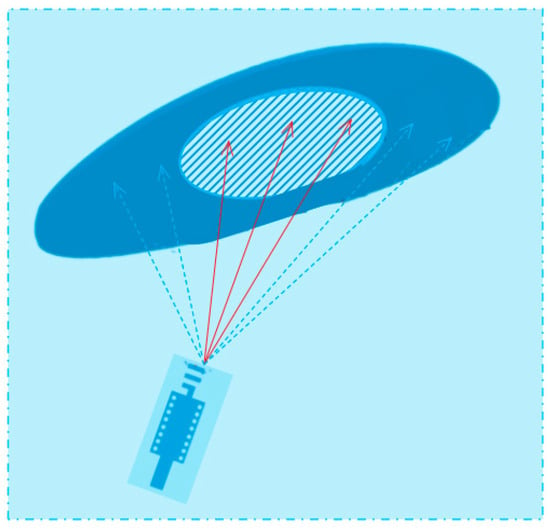
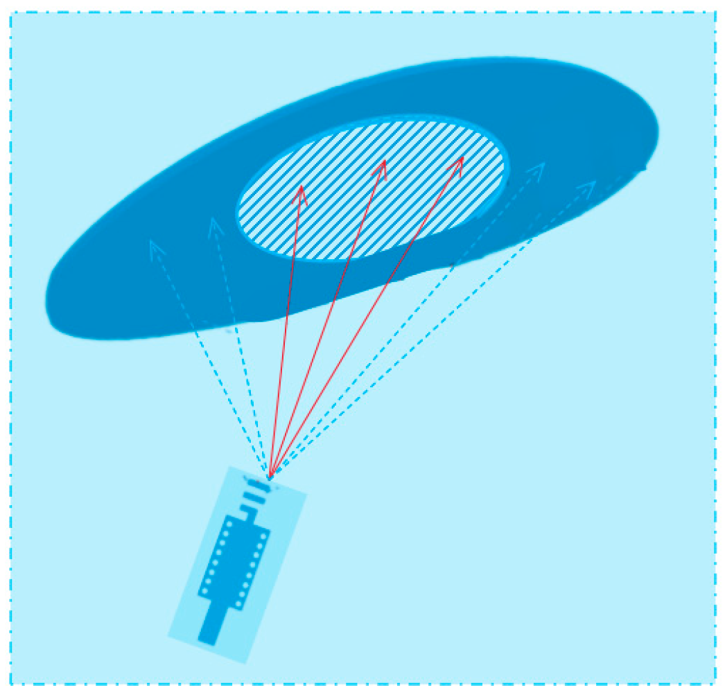
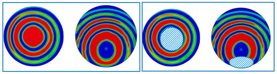
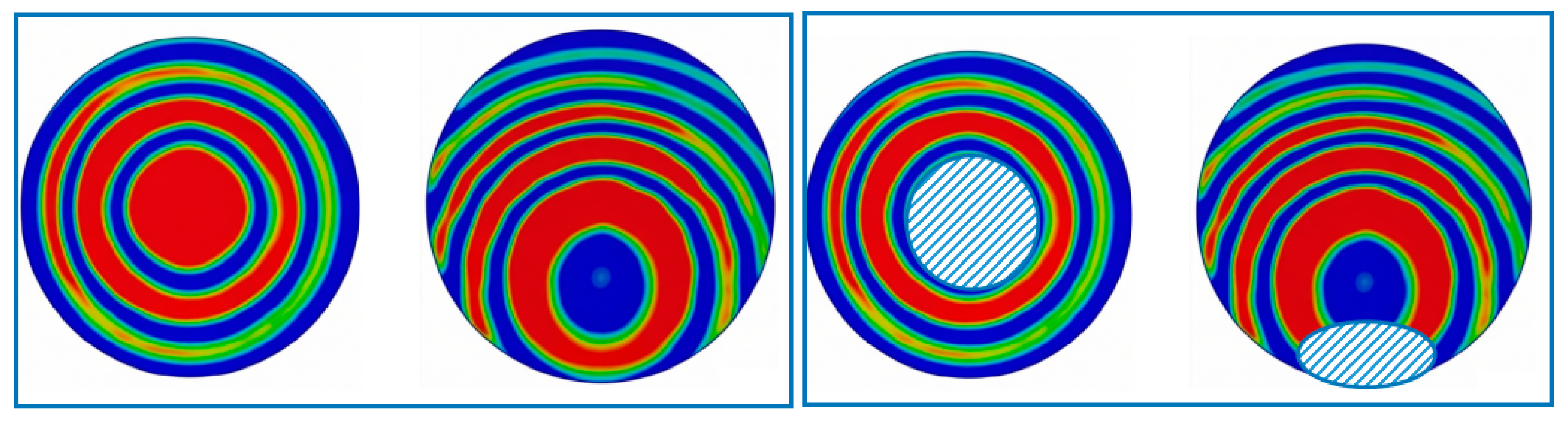
Figure 5 presents the illumination intensity distribution diagrams of the Cassegrain secondary reflector under vertical irradiation and oblique incidence, with the tilted corrugation adopted as the shielding effect diagram of the feed blockage (shown in the right sub-figure). It can be observed that under vertical irradiation, i.e., when the feed antenna is not rotated, the illumination intensity exhibits excellent symmetry, yet the central area is blocked. When the feed is tilted by 15 degrees, the illumination intensity distribution on the secondary reflector changes, and the blockage is simultaneously located at the lower part.
Figure 5.
Cassegrain sub-reflector under normal vertical irradiation and oblique incidence.
Table 2 includes two configurations, their shielding angles, and the corresponding blockage losses. For the symmetric Cassegrain reflector with unrotated feed (Configuration B), the shielding angle is 17π/36–19π/36, and the blockage is 30%. For Configuration C, after rotating the feed by π/12, the shielding angle becomes 5π/12–4π/9, and the blockage loss is reduced to 8%. It is clear that rotating the feed counterclockwise by π/12 moves the subreflector outside the outgoing beam path of the main reflector, thereby mitigating the blockage. At the same time, the subreflector expands the feed beam and provides more uniform illumination of the main reflector.
Table 2.
The blockage loss of the Cassegrain.
It should be emphasized that, compared with a planar array [7], the adopted wide-beam feed antenna provides a shorter signal transmission path, which reduces the PCB dielectric loss along the feed and, more importantly, minimizes the blockage effect. By rotating the feed (Configuration C), the blockage loss is improved. This is achieved at the cost of tolerating a higher spillover loss, since a wide-beam feed intercepts a smaller fraction of the available aperture energy. The radiation efficiency of the metal-coated reflector is not the primary optimization target of this work; rather, the core contribution lies in the multi-dimensional trade-off among blockage, spillover, and feed-path transmission loss. The resulting compact, low-profile feed can be seamlessly integrated with backend active modules—an advantage that a conventional horn feed cannot offer, and one that would not be attainable with a horn-fed narrow-beam alternative.
2.3. Offset Cassegrain Reflector
In the design of the proposed dual reflector, a parabolic surface is selected as the main reflector. Following the formulation in [15], the hyperboloid of the subreflector [20] can be expressed in polar coordinates with respect to its virtual focus as
where ρ is the radial distance from the virtual focus, ф is the polar angle measured from the reflector axis, e denotes the eccentricity of the hyperbola, and p1 is the semi-latus rectum. For the subreflector to properly intercept the rays reflected from the main reflector, the angular range of the hyperboloid, as seen from its virtual focus, is chosen to coincide with the illumination angle subtended by the main reflector. Accordingly, the main reflector, which is a paraboloid of revolution, is described by
where p is the focal parameter, i.e., the distance from the vertex to the focus, of the paraboloid.
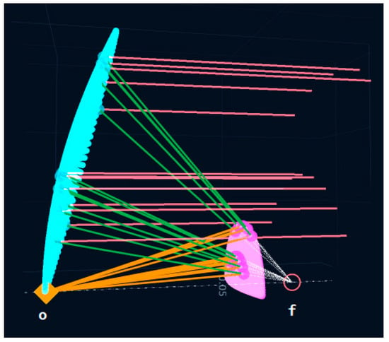
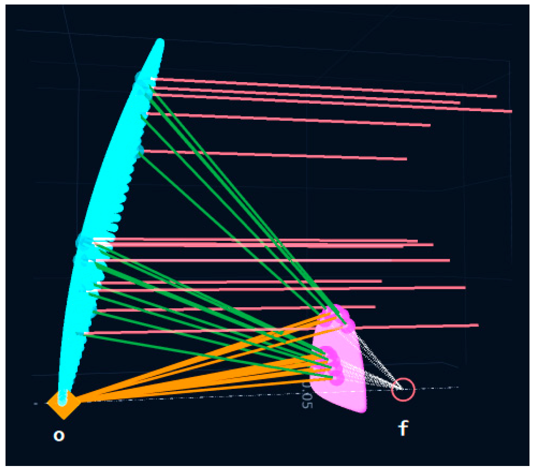
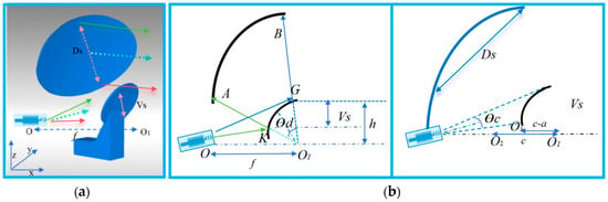
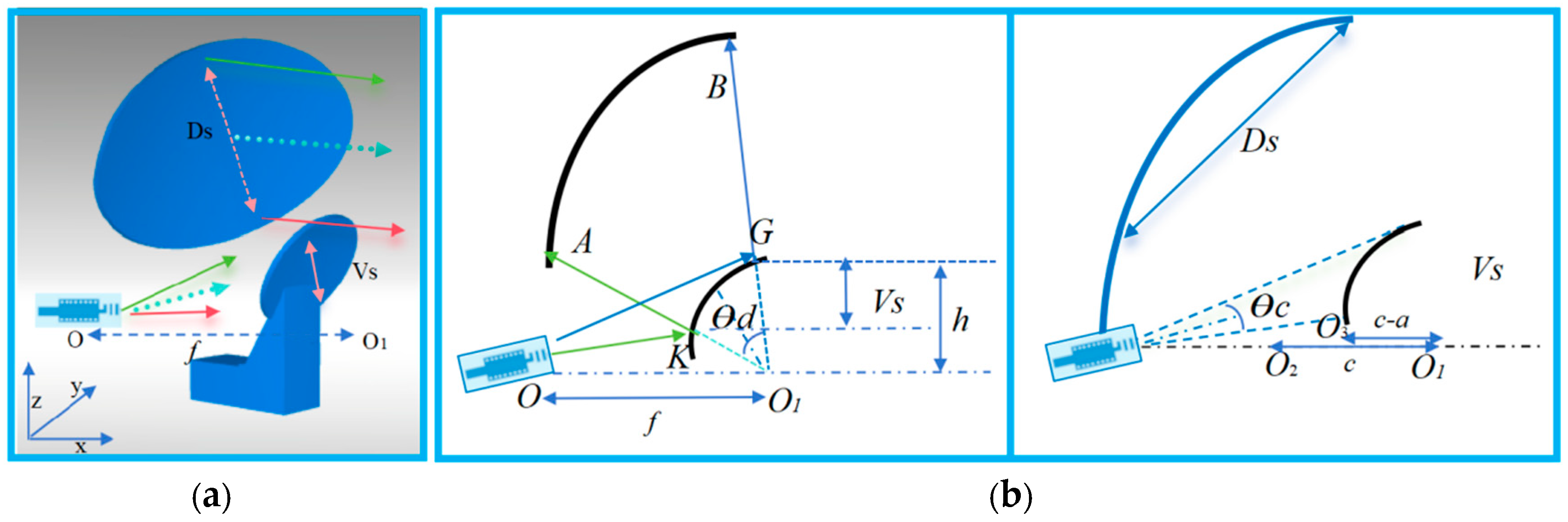
Since the distance from the feed phase center o to the focal point of the main reflector is f, as indicated in Figure 6, and given the eccentricity e = 2 for the subreflector hyperbola, we can readily derive the geometric parameters of the hyperboloid. For a hyperbola, the focal distance c and the semi-major axis a satisfy c = ea. With e = 2 and noting from Figure 6 that the separation between the virtual focus and the real focus of the hyperbola, which is coincident with the feed phase center o and the focal point of the main reflector, respectively, is equal to f, we obtain
Figure 6.
Geometry of the offset Cassegrain reflector with simple ray tracing illustration.
Substituting c = 2a yields
The typical geometric parameters of the offset Cassegrain reflector are annotated in Figure 7. The angular coordinate ϕ in Equations (1) and (2) is determined by the beam width of the feed antenna-specifically, its −10 dB or −3 dB taper angles. In this design, a wide-beam planar SIW-fed Yagi-Uda antenna is employed, which provides a well-defined illumination taper. Consequently, the relationships between the key parameters labeled in Figure 7 are derived via straightforward ray tracing. The resulting expressions are given as follows:
Figure 7.
The offset Cassegrain 3D view (a) and the offset Cassegrain reflector with parameter (b).
The vertical offset of the subreflector vertex from the main reflector axis is
The distance between the two edges of the main reflector, i.e., the aperture diameter, is obtained from the law of cosines as
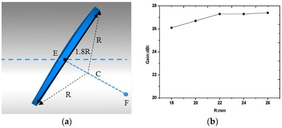
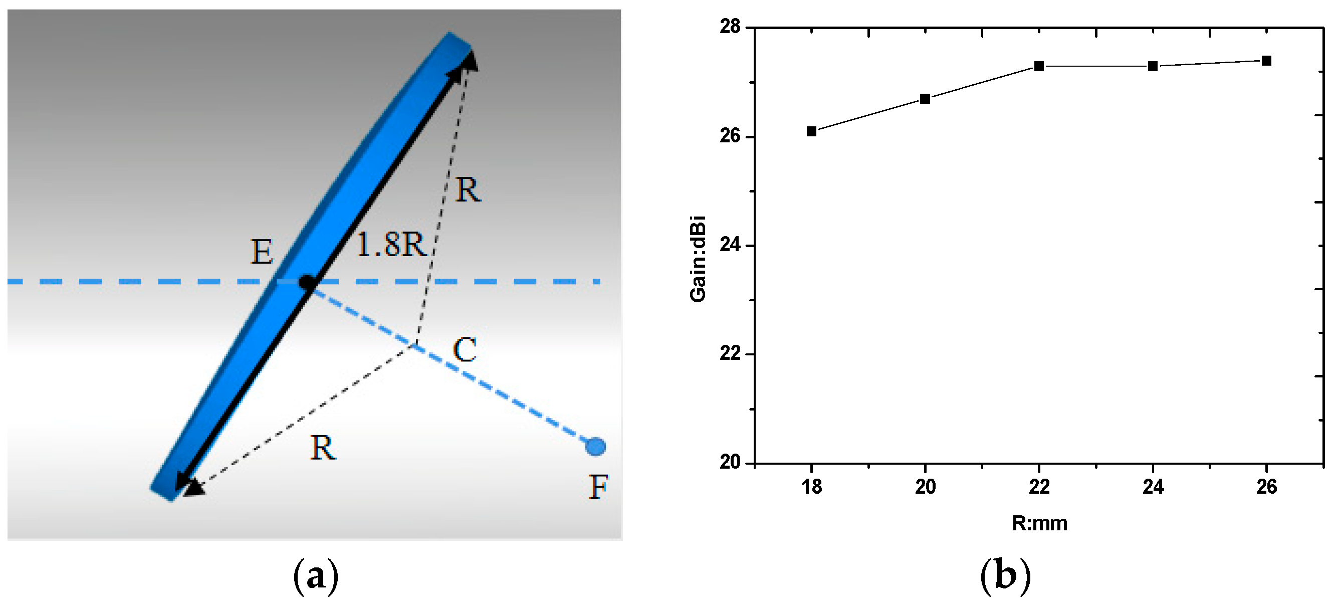
The above expressions were derived based on a simple ray-tracing analysis and require further validation. In this study, we employ Ansys HFSS to investigate the influence of the subreflector radius on the system gain, with the main reflector focal length set to f = 50 mm for all simulation cases. Within the HFSS simulation framework, the feed antenna is modeled using the finite element method (FEM) to ensure accurate characterization of near-field radiation, while the electrically large reflector surfaces are solved using the physical optics (PO) method to reduce unnecessary computational cost while maintaining high far-field calculation accuracy. It is evident that the performance of the dual-reflector antenna depends not only on the main reflector but also critically on the subreflector aperture size. To examine this effect, firstly, a geometric parameter R is defined as the radius of the circumscribed circle of the subreflector cross-section in the xz plane, as depicted in Figure 8a. The simulated radiation gain as a function of R is plotted in Figure 8b. Provided R is excessively small, the subreflector intercepts only a fraction of the energy radiated by the feed antenna. As a consequence, increasing R is beneficial for the efficient energy transfer from the subreflector to the main reflector. However, as R exceeds a certain threshold, the subreflector begins to block the aperture of the main reflector, which inevitably degrades the overall performance of the proposed dual-reflector antenna.
Figure 8.
The definition of R (a) and the radiation Gain of the proposed dual reflector as the function of R (b), which represents the aperture of the subreflector.
The above parametric study reveals a trade-off: increasing R improves energy interception by the subreflector, but an excessively large R introduces blockage to the main reflector. To better interpret this behavior, we recall the classical radiation gain expression for a dual-reflector antenna [15]:
where ηm and ηs denote the interception efficiencies of the main reflector and the subreflector respectively; S is the aperture area of the main reflector, and the free-space wavelength of the operating frequency. According to (7), a larger aperture generally leads to a higher gain. However, as shown in Figure 8b, G remains almost unchanged at around 27.0 ± 0.5 dBi once R exceeds a certain value, which implies that the effective radiation aperture of the subreflector no longer increases with R, and consequently ηs remains essentially constant. In other words, beyond this point, the enlarged subreflector only adds blockage without contributing to further gain enhancement.
2.4. Simulation Model and Numerical Details
The complete model is analyzed in Ansys HFSS 2023 R1 with a hybrid FEM-PO strategy: the electrically small feed and the large reflectors (Dg = 105 mm, i.e., about 21 λ0 at 60 GHz) are solved separately and coupled through a field link. This decomposition keeps the fine mesh required by the SIW structure apart from the electrically large reflector problem, so that the memory and time cost is governed by the feed rather than by the reflector aperture.
The SIW-fed Yagi–Uda antenna is solved with the driven-modal solver. The substrate is lossy (Rogers RT/duroid 5880, εr = 2.2, tanδ = 0.0009, h = 0.508 mm) and all metallization, including the SIW via fence, is copper (σ = 5.8 × 10⁷ S/m). A first-order radiation boundary is set 5 mm away from the radiating structure (>λ0/4 = 1.32 mm at 57 GHz), and the excitation is a wave port at the microstrip-to-SIW transition. The mesh uses λ0/3 refinement in vacuum and λg/3 in the substrate, with local elements of λ0/30 (0.18 mm) enforced on the via fence, on the ground slots, and on the SIW-to-Yagi transition, where the current density varies most rapidly.
Adaptive refinement is carried out at 61 GHz and at both band edges (57 and 64 GHz). Each solution is considered converged when the change in the S-parameters falls below ΔS ≤ 0.02, which is reached within six to twenty passes, while the peak realized gain is monitored until its variation between two successive passes is below 0.05 dB. An interpolating sweep then covers 57–64 GHz in 0.25 GHz steps, fine enough to resolve the impedance ripple of the SIW transition.
The main and the sub-reflectors are defined as PO regions illuminated by the near field of the FEM feed, and the induced currents are integrated to obtain the secondary far field. Perfect-conductor surfaces are justified by the copper coating (≥1 μm, i.e., more than 3.7 skin depths at 60 GHz). Facets of λ0/10 are used, refined to λ0/20 along the rim and on the sub-reflector; refining the facets from λ0/6 to λ0/10 and λ0/20 changes the gain by less than 0.1 dB and 0.05 dB, respectively, so the λ0/10 mesh is adopted throughout. Edge diffraction is neglected, which affects mainly the far sidelobes, and multiple reflections between the reflector and the sub-reflector are neglected as well, consistent with the weak coupling reported for offset configurations [21,22].
3. Antenna Fabrication and Experimental Results
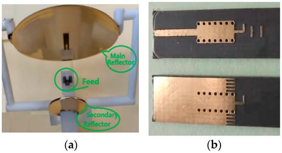
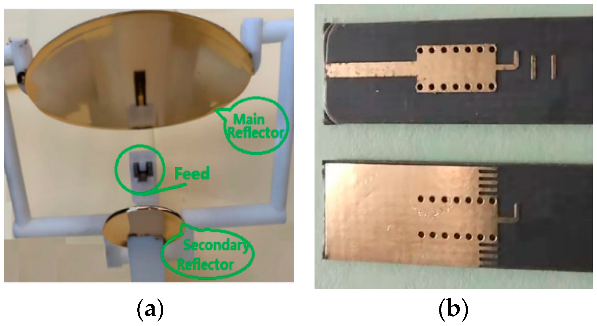
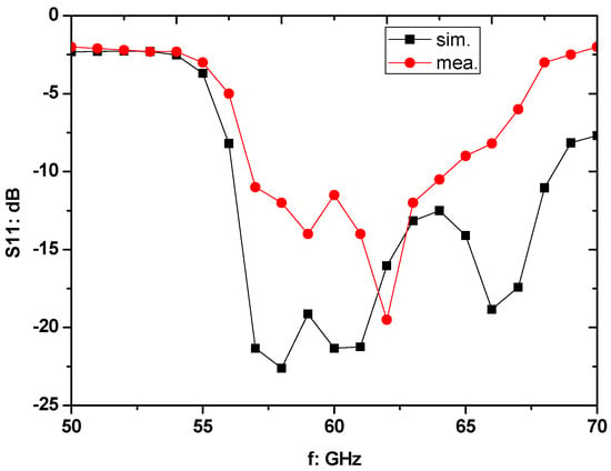
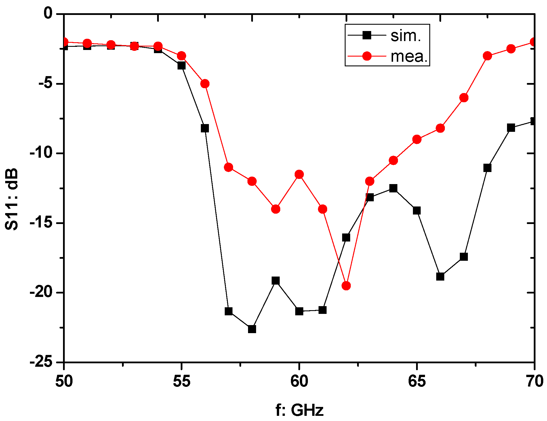
Figure 9b presents the geometry of the proposed SIW-fed planar Yagi-Uda antenna, with the specific values listed in Table 1. This feed antenna is fabricated on a Rogers RT/duroid 5880 substrate with a dielectric constant of 2.2 and a thickness of 0.508 mm. The input impedance of the Yagi-Uda antenna is measured with a vector network analyzer (Keysight N5247B, Irvine, CA, USA). As seen in Figure 9b, the microstrip line is designed as a transition from a microwave connector to the SIW. The measured S-parameters are plotted in Figure 10 together with the simulated results. Over the 57–64 GHz band, both the simulated and measured S11 remain below −10 dB, indicating fairly good agreement. Discrepancies between them might be attributed to variations in substrate permittivity, the embedded microwave connector, and fabrication tolerances. Since the coupling between the offset feed antenna and the reflectors is negligible [21,22], the measured S11 of the feed antenna can be used to approximate the S11 of the complete dual-reflector antenna.
Figure 9.
Fabrication prototypes: (a) the dual-reflector antenna and (b) the SIW-fed planar Yagi-Uda feed antenna.
Figure 10.
S11 of the proposed Yagi-Uda antenna.
The fabricated dual-reflector antenna prototype is demonstrated in Figure 9a; its key geometric parameters and the fabrication process parameters of these reflectors are listed in Table 3 and Table 4, respectively. Since the subreflector is no longer perpendicular to the feed, the illumination on it is broadened in the horizontal direction and compressed in the vertical direction, as can be observed from the illumination intensity distributions in Figure 5. Accordingly, the major axis of the main reflector is oriented perpendicular to the plane of the paper (Dg = 105 mm), which gives an elliptical aperture with S = 0.0056 m2; the cross-section of the main reflector is therefore not circular.
Table 3.
Key geometric parameters.
Table 4.
Fabrication process parameters.
As shown in Table 4, compared with a pure metallic structure, the combination of resin, 3D printing, and vacuum deposition (sputtering) can effectively reduce the weight. The density of stainless steel powder is 7.9 g/cm3, while that of pure resin powder is 0.9 g/cm3. Effective weight reduction is therefore achieved, with the weight substantially reduced. The reflector area is S = 0.0056 m2, and the thickness is 3 mm, giving a volume of V = 16.8 cm3. For stainless steel with a density of 7.9 g/cm3, the mass is 132.72 g. For resin with a density of 0.9 g/cm3, the mass is 15.12 g. But the mass measured by an electronic balance is 18.5 g (the metal coating weighs 1 g), as shown in Figure 11. The theoretical calculation assumes a flat elliptical area, while the real reflector surface is a concave curved one. The weight reduction ratio is more than 80%, which remains a substantial improvement over the full-metal counterpart.
Figure 11.
The weight of the main reflector.
The radiation pattern and gain measurements of the proposed dual-reflector antenna were performed in a far-field anechoic chamber equipped with an arch-based scanning system. A standard gain horn (QSH16S60) is used as the transmitting antenna. The antenna under test (AUT) was mounted on a foam holder with a relative permittivity of approximately 1.05, whose scattering effect is negligible. A substitution method was employed for calibration, using the standard gain horn as the reference. The far-field condition was verified using R ≥ 2D2/λ, where D is the aperture diameter of the AUT and λ is the free-space wavelength. The actual measurement distance was approximately 5 m, which satisfies the far-field criterion over the entire 57–64 GHz operating band. Following the GUM guide, the uncertainty sources in the gain measurement were evaluated item by item, as detailed in Table 5, including VNA amplitude accuracy, cable and connector repeatability, AUT alignment, far-field distance, chamber reflections, foam holder scattering, and standard gain horn calibration uncertainty. As indicated in Table 5, the total gain at all operating frequency points remains highly stable, with a measurement uncertainty of approximately 0.5 dB.
Table 5.
Uncertainty budget for gain measurement.
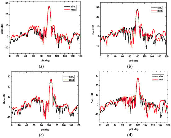
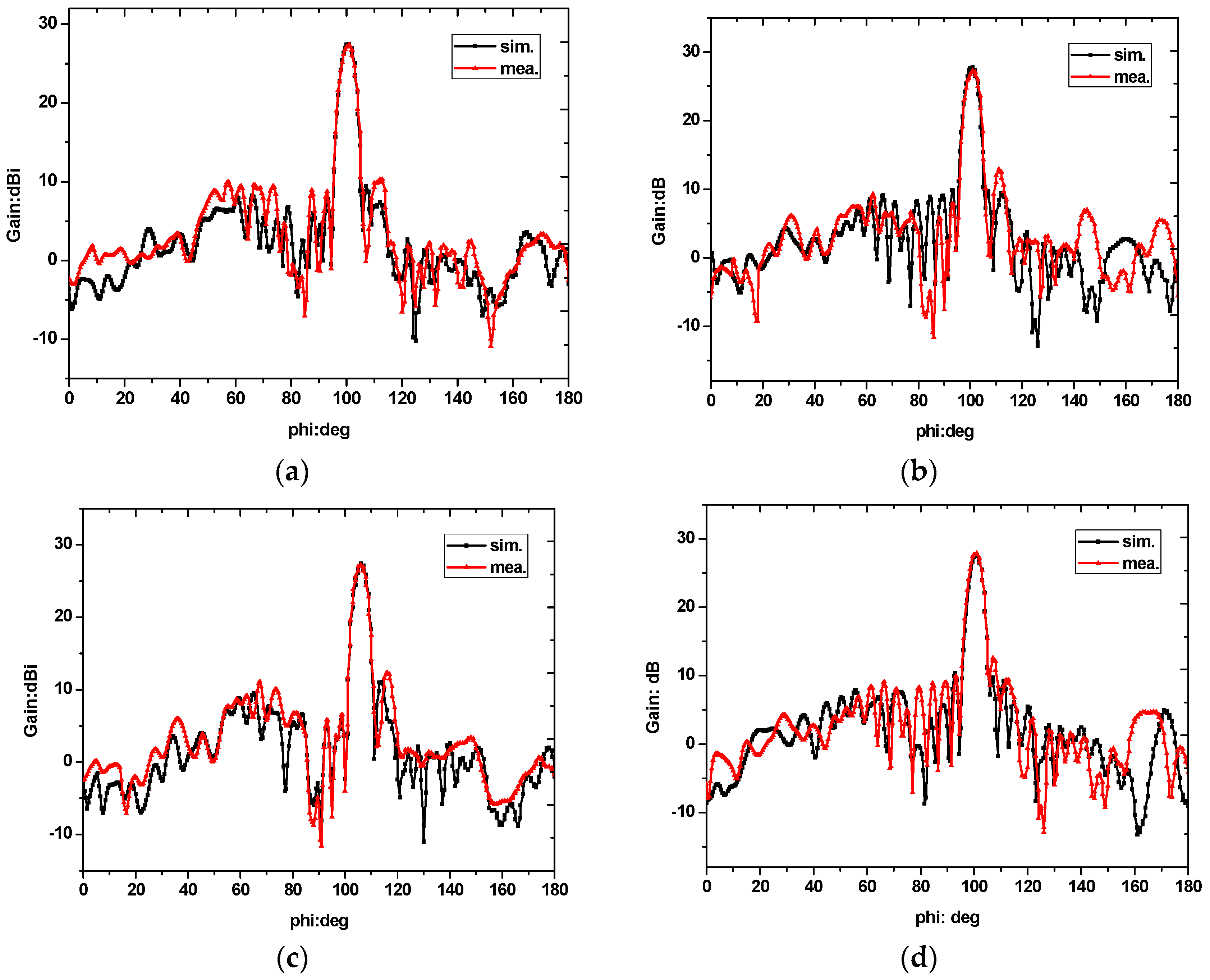
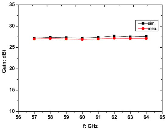
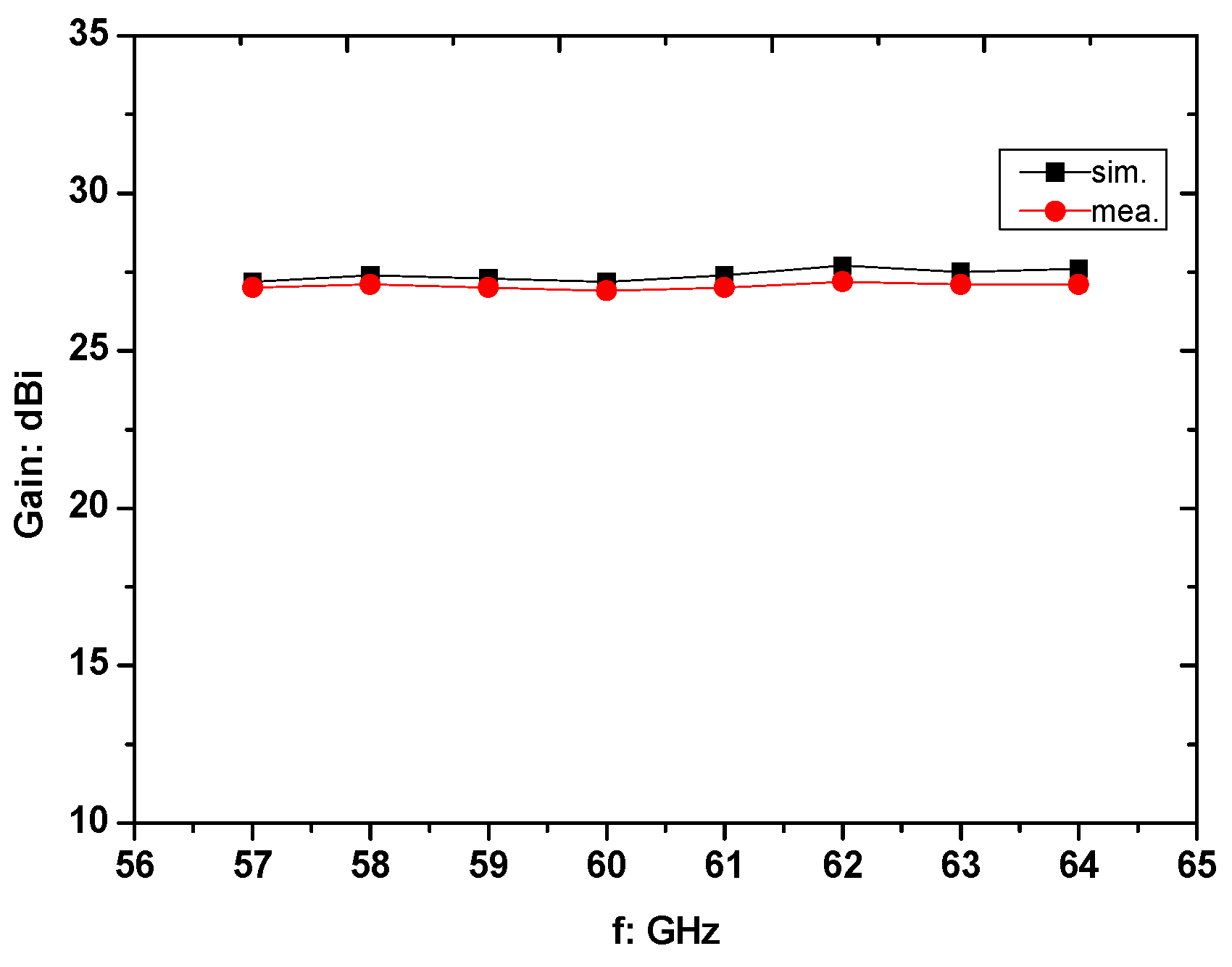
The simulated and measured radiation patterns at 57 GHz, 59 GHz, 61 GHz, and 64 GHz are compared in Figure 12. Across all these operating frequencies, as discussed before, the measured gain is approximately 27 ± 0.5 dBi as shown in Figure 13, while the measured sidelobe levels are slightly higher than the simulated. Nonetheless, all measured sidelobes remain more than 14 dBi below the main beam, which meets the requirements of low-sidelobe designs. The main beam points at a scan angle of 105° across the full operating band, indicating stable beam pointing.
Figure 12.
Simulated and measured radiation patterns at 57 GHz (a), 59 GHz (b), 61 GHz (c), and 64 GHz (d), respectively.
Figure 13.
Simulated and measured gain at 57–64 GHz.
Finally, Table 6 compares the proposed antenna with several previously reported reflector antennas [23,24,25,26,27,28]. It can be observed that the 3D-printed reflector antennas in [27,28] exhibit distinct advantages in high-performance characteristics. Among them, the design in [27] shows the most prominent bandwidth advantage, achieving a fractional bandwidth of 48%. Under the condition of similar profile dimensions and operating frequency, the above 5 dB higher gain (peak directivity 33 dBi) of the antenna in [28] is attributed to the adoption of a horn structure as the feed, whereas this feed antenna cannot be seamlessly integrated with active modules. Although the antennas operating at 94 GHz in [23,24,25] possess higher gain, this performance improvement comes at the cost of a significantly enlarged aperture size. In contrast, the proposed antenna in this work achieves a peak gain of 27 dBi with an extremely compact aperture area of only 0.0056 m2, which is even smaller than the 0.0095 m2 aperture of the reported 38 GHz antenna in [26]. Therefore, this dual-reflector antenna features the design merits of a compact footprint and low profile, making it highly suitable for 60 GHz communication scenarios. It is noted that the radiation efficiency of the proposed antenna was measured using a gain-directivity separation method. First, the absolute gain was measured by the gain-transfer (comparison) method, and the directivity was obtained by integrating the measured radiation pattern over a spherical surface. The radiation efficiency was then calculated as the ratio of the absolute gain to the directivity. Although a conventional horn feed can provide higher gain and better symmetry, it cannot be seamlessly integrated with backend active modules, which is the principal motivation for the proposed SIW-fed planar Yagi-Uda feed; compared with purely PCB-based arrays, the proposed feed reduces the transmission-path loss while preserving full integrability with active circuits.
Table 6.
Comparison between proposed and reported reflector antennas.
4. Conclusions
In this paper, a high-gain dual-reflector antenna for 60 GHz millimeter-wave applications has been designed, fabricated using 3D printing and vacuum deposition, and experimentally validated. A SIW-fed planar Yagi-Uda antenna is used as the feed antenna, which can be seamlessly integrated with a microwave active module. This offset Cassegrain configuration, featuring an offset-fed main reflector and a hyperbolic subreflector, effectively expands the coverage of the feed beam and simultaneously suppresses the blockage effect inherent in conventional Cassegrain antennas. The measured results demonstrate a maximum gain of 27 dBi over a 7 GHz bandwidth (57–64 GHz). Compared with previously reported reflector antennas operating at similar or even lower frequencies, the proposed dual-reflector antenna achieves competitive gain performance with a significantly more compact aperture. These features make it a promising candidate for low-profile, high-gain millimeter-wave communication systems. Future work will focus on further performance enhancement through reflector surface shaping and optimization of the feed positioning.
In summary, the design philosophy of this work is a deliberate multi-objective trade-off among blockage, spillover, and feed-path transmission loss. By employing a wide-beam SIW-fed Yagi–Uda feed, the proposed dual-reflector antenna reduces the blockage ratio from 30% to 8% and shortens the lossy PCB feed path, while intentionally tolerating a higher spillover loss and, consequently, a lower aperture efficiency than a horn-fed narrow-beam alternative. This trade-off is justified by the 27 xs, which confirms its practical viability, and by the compact, integratable structure that enables seamless co-integration with active modules. The overall efficiency ηoverall is the product of the radiation efficiency ηrad and the aperture efficiency ηap, as listed below.
The radiation efficiency of the metal-coated reflector remains high (≈70%, estimated from the measured 27 dBi gain together with the full-space-integrated directivity and dominated by the dielectric loss of the feed substrate and the PCB feed path), whereas the aperture efficiency—governed by illumination taper, spillover, and blockage—is the dominant factor and is deliberately relaxed in favor of reduced blockage and improved system integration.
Author Contributions
B.C. was responsible for developing the methodology, designing the experiment, and writing the paper. L.L. provided support for EM software simulation and reviewed the paper. All authors have read and agreed to the published version of the manuscript.
Funding
This research was funded by the Natural Science Foundation of the Zhejiang Provincial Education Department under Grant Y202249485.
Data Availability Statement
The datasets generated and analyzed during this study are available in the ScienceDB(chinese scidb), accessible via https://doi.org/10.57760/sciencedb.43997.
Conflicts of Interest
The authors declare no conflicts of interest.
References
- Wei, X.; Gang, D.; Wang, Y.; Zhu, Z.M.; Yang, Y.T. 3-D Compact Marchand Balun Design Based on Through-Silicon via Technology for Monolithic and 3-D Integration. IEEE Trans. VLSI Syst. 2022, 30, 1200–1208. [Google Scholar] [CrossRef] [Scilit]
- Lamminen, A.E.I.; Saily, J.; Vimpari, A.R. 60-GHz patch antennas and arrays on LTCC with embedded-cavity substrates. IEEE Trans. Antennas Propag. 2008, 56, 2865–2874. [Google Scholar] [CrossRef] [Scilit]
- Yang, T.Y.; Hong, W.; Zhang, Y. Wideband millimeter-wave substrate integrated waveguide cavity-backed rectangular patch antenna. IEEE Antennas Wirel. Propag. Lett. 2014, 13, 205–208. [Google Scholar] [CrossRef] [Scilit]
- Li, M.J.; Luk, K.M. A low-profile unidirectional printed antenna for millimeter-wave applications. IEEE Trans. Antennas Propag. 2013, 62, 1232–1237. [Google Scholar] [CrossRef] [Scilit]
- Cheng, S.; Yousef, H.; Kratz, H. 79 GHz slot antennas based on substrate integrated waveguides (SIW) in a flexible printed circuit board. IEEE Trans. Antennas Propag. 2009, 57, 64–71. [Google Scholar] [CrossRef] [Scilit]
- Guntupalli, A.B.; Wu, K. 45° linearly polarized high-gain antenna array for 60-GHz radio. IEEE Antennas Wirel. Propag. Lett. 2014, 13, 384–387. [Google Scholar] [CrossRef] [Scilit]
- Hao, Z.C.; He, M.; Fan, K.K.; Luo, G.Q. A Planar Broadband Antenna for the E-Band Gigabyte Wireless Communication. IEEE Trans. Antennas Propag. 2017, 65, 1369–1373. [Google Scholar] [CrossRef] [Scilit]
- Hosseini, A.; Kabiri, S.; De Flaviis, F. V-Band High-Gain Printed Quasi-Parabolic Reflector Antenna With Beam-Steering. IEEE Trans. Antennas Propag. 2017, 65, 589–591. [Google Scholar] [CrossRef] [Scilit]
- Auria, M.D.; Otter, W.J.; Hazell, J.; Gillatt, B.T.W.; Long-Collins, C.; Ridler, N.M.; Lucyszyn, S. 3-D printed metal-pipe rectangular waveguides. IEEE Trans. Compon. Packag. Manuf. Technol. 2015, 5, 1339–1349. [Google Scholar] [CrossRef] [Scilit]
- Nguyen, N.T.; Delhote, N.; Ettorre, M.; Baillargeat, D.; Coq, L.; Sauleau, R. Design and characterization of 60-GHz integrated lens antennas fabricated through ceramic stereolithography. IEEE Trans. Antennas Propag. 2010, 58, 2757–2762. [Google Scholar] [CrossRef] [Scilit]
- Nayeri, P.; Liang, M.; Sabory-Garcı´a, R.A.; Tuo, M.; Yang, F.; Gehm, M.; Xin, H.; Elsherbeni, A.Z. 3D printed dielectric reflectarrays: Low-cost highgain antennas at sub-millimeter waves. IEEE Trans. Antennas Propag. 2014, 62, 2000–2008. [Google Scholar] [CrossRef] [Scilit]
- Cai, B.X.; Sun, L.L.; Lei, Y.C. 3D Printing Using a 60 GHz Millimeter Wave Segmented Parabolic Reflective Curved Antenna. Electronics 2019, 8, 203–213. [Google Scholar] [CrossRef] [Scilit]
- Wu, J.; Wang, C.; Guo, Y.X. A compact reflector antenna fed by a composite s/ka-band feed for 5g wireless communications. IEEE Trans. Antennas Propag. 2020, 68, 7813–7821. [Google Scholar] [CrossRef] [Scilit]
- Alhalabi, R.A.; Chiou, Y.C.; Rebeiz, G.M. Self-shielded high-efficiency Yagi-Uda antennas for 60 GHz communications. IEEE Trans. Antennas Propag. 2011, 59, 742–750. [Google Scholar] [CrossRef] [Scilit]
- Stutzman, W.L.; Thiele, G.A. Antenna Theory and Design; John Wiley & Sons: Hoboken, NJ, USA, 1997. [Google Scholar]
- Xu, F.; Wu, K. Guided-wave and leakage characteristics of substrate integrated waveguide. IEEE Trans. Microw. Theory Tech. 2005, 53, 66–73. [Google Scholar] [CrossRef] [Scilit]
- Cassivi, Y.; Perregrini, L.; Arcionni, P.; Bressan, M.; Wu, K.; Conciauro, G. Dispersion characteristics of substrate integrated rectangular waveguide. IEEE Microw. Wirel. Compon. Lett. 2002, 12, 333–335. [Google Scholar] [CrossRef] [Scilit]
- Che, W.; Deng, K.; Wang, D.; Chow, Y.L. Analytical equivalence between substrate-integrated waveguide and rectangular waveguide. IET Microw. Antennas Propag. 2008, 2, 35–41. [Google Scholar] [CrossRef] [Scilit] [PubMed]
- Sharma, S.K.; Rao, S.; Shafai, L. Handbook of Reflector Antennas and Feed Systems: V. 1 Theory and Design of Reflectors; Artech House: New York, NY, USA, 2013. [Google Scholar]
- Brown, K.W.; Lee, Y.H.; Prata, A.J. A systematic design procedure for classical offset dual reflector antennas with optimal electrical performance. In Proceedings of the Antennas & Propagation Society International Symposium, San Antonio, TX, USA, 16–21 June 2002. [Google Scholar]
- Hu, W.; Arrebola, M.; Cahill, R.; Encinar, J.A. 94 GHz dual-reflector antenna with reflectarray subreflector. IEEE Trans. Antennas Propag. 2009, 57, 3043–3050. [Google Scholar] [CrossRef] [Scilit]
- Wan, J.X.; Yan, T.; Wang, F. A Hybrid Reflector Antenna for Two Contoured Beams With Different Shapes. IEEE Antennas Wirel. Propag. Lett. 2018, 17, 1171–1175. [Google Scholar] [CrossRef] [Scilit]
- Nova, E.; Rodrigo, D.; Romeu, J.; Jofre, L. 94 GHz Cassegrain reflector antenna performance characterization. In Proceedings of the 6th European Conference on Antennas and Propagation (EUCAP), Prague, Czech Republic, 26–30 March 2012; pp. 3442–3445. [Google Scholar]
- Wang, J.; Lin, H.; Yang, F.; Ge, J.X. Design of 94 GHz Dual-Polarization Antenna Fed by Diagonal Horn for Cloud Radars. IEEE access. 2022, 10, 22480–22485. [Google Scholar] [CrossRef] [Scilit]
- Yu, B.; Xia, H.; Chen, X.; Yang, F.; Ge, J.X. A novel W-band dual polarized Cassegrain antenna for cloud radar. Prog. Electromagn. Res. Lett. 2016, 61, 99–103. [Google Scholar] [CrossRef] [Scilit]
- Mei, P.; Zhang, S.; Pedersen, G.F. A Wideband 3D Printed Reflectarray Antenna with Mechanically Reconfigurable Polarization. IEEE Antennas Wirel. Propag. Lett. 2020, 19, 1798–1802. [Google Scholar] [CrossRef] [Scilit]
- Vaquero, A.F.; Rebollo, A.; Arrebola, M. Additive manufacturing in compact high-gain wideband antennas operating in mm-wave frequencies. Sci. Rep. 2023, 13, 10998. [Google Scholar] [CrossRef] [Scilit] [PubMed]
- Sanchez, R.T.; Breinbjerg, O.; Kim, O.S. 3D-metal-printed 60 GHz offset dual-reflector antenna with integrated conical feed horn and circular-to-rectangular waveguide transition. In Proceedings of the 12th European Conference on Antennas and Propagation (EuCAP), London, UK, 9–13 April 2018; pp. 1–5. [Google Scholar]



Disclaimer/Publisher’s Note: The statements, opinions and data contained in all publications are solely those of the individual author(s) and contributor(s) and not of MDPI and/or the editor(s). MDPI and/or the editor(s) disclaim responsibility for any injury to people or property resulting from any ideas, methods, instructions or products referred to in the content. |
© 2026 by the authors. Licensee MDPI, Basel, Switzerland. This article is an open access article distributed under the terms and conditions of the Creative Commons Attribution (CC BY) license.