


Abstract
Ultra-wideband (UWB) technology has been widely applied to indoor positioning due to its high-precision ranging. In practical indoor scenarios, inertial measurement units (IMUs) are commonly fused with UWB to suppress measurement errors caused by non-line-of-sight (NLOS) propagation. Frequent switching between line-of-sight (LOS) and NLOS conditions easily generates severe outliers in UWB ranging data. Furthermore, the conventional extended Kalman filter (EKF) lacks an adaptive adjustment mechanism for innovation covariance, which significantly reduces the positioning robustness of the fusion system. To address the above issues, this paper establishes a tightly coupled UWB/IMU positioning model for complex indoor scenarios and proposes an improved robust adaptive extended Kalman filter (IR-AEKF) algorithm. After calibrating UWB ranging errors, IMU bias, and scale factor errors, the system state equation and UWB ranging observation model are constructed under the tightly coupled fusion framework. On this basis, innovation statistics are leveraged to incorporate Huber-type weights and adaptive scaling factors that dynamically tune the observation noise covariance matrix. Meanwhile, a ranging outlier elimination threshold is set to suppress gross errors induced by NLOS interference. Experimental results demonstrate that the IR-AEKF can effectively suppress disturbances arising from abnormal ranging outliers. In dynamic positioning tests, the mean positioning errors along the X-axis and Y-axis are 0.032 m and 0.035 m, respectively. The IR-AEKF provides an effective technical solution for UWB/IMU fusion positioning in complex indoor environments.
1. Introduction
With the advent of the Internet of Things (IoT), the public demand for high-precision location-based services has witnessed a sustained surge [1,2]. Global navigation satellite system (GNSS) and real-time kinematic (RTK) technologies are capable of delivering high-precision positioning and navigation for outdoor scenarios. Nevertheless, building walls and internal structures inside indoor and underground spaces lead to satellite signal blockage, attenuation, and multi-path interference. These signal distortions degrade observation quality, precluding the derivation of reliable positioning solutions [3].
UWB is a cutting-edge wireless communication technology that transmits signals via nanosecond-scale pulses, achieving centimeter-level ranging accuracy and spatial positioning capability under LOS propagation conditions [4,5]. Owing to its excellent anti-interference performance and reliable ranging characteristics, UWB has become one of the mainstream technologies for precise indoor positioning. Nevertheless, indoor walls and other obstacles obstruct the direct propagation path between UWB anchors and tags, which inevitably triggers NLOS ranging errors and substantially deteriorates the overall positioning accuracy of the UWB system [6,7]. To mitigate NLOS interference, Liu et al. [8] carry out multiple binary hypothesis tests based on the signal to noise ratio (SNR) of UWB signals and adopt a sliding window to filter out abnormal ranging data. Wang et al. [9] built an LOS/NLOS map by leveraging prior environmental information, with which the Kalman filter (KF) was calibrated to mitigate the NLOS-induced errors. Yang et al. [10] proposed the bidirectional encoder representations from transformers (BERT) model to extract features of UWB channel impulse response (CIR) and implement NLOS path classification. This scheme significantly enhanced the ranging accuracy. Nevertheless, the conventional UWB indoor positioning method requires densely deployed anchors to mitigate positioning blind zones. In addition, ranging outliers arising from LOS/NLOS state transitions readily lead to transient fluctuations in position estimation. Accordingly, a standalone UWB system is limited for practical positioning amid frequent LOS/NLOS transitions.
IMUs are immune to signal blockage and deliver direct readouts of pose parameters and kinematic data for moving carriers [11]. Nevertheless, long-duration running of IMU induces drift in gyroscope and accelerometer, which accumulates into unbounded positioning errors and impairs reliability and accuracy of positioning system [12]. The UWB/IMU integrated positioning system can effectively compensate for the technical drawbacks of individual sensors. Specifically, the UWB subsystem constrains the unbounded accumulated positioning errors inherent to IMU mechanization, while the IMU subsystem serves to smooth the range jitters observed in standalone UWB localization.
The tightly coupled UWB/IMU positioning method directly fuses raw UWB ranging observations and IMU measurements (i.e., acceleration and angular velocity) during filter update iterations. This approach real-time compensates for the drift of the IMU and effectively alleviates NLOS errors [13,14]. Li et al. [15] proposed a tightly coupled UWB/IMU positioning method based on the maximum correlation filter. By dynamically tuning the weights of UWB measurements, this approach alleviated the deterioration of positioning accuracy induced by UWB ranging outliers in non-Gaussian conditions. Sui et al. [16] utilized a gray prediction model to calibrate UWB ranging measurements, which effectively mitigates positioning error under NLOS environments. Sun et al. [17] designed a tightly coupled UWB/IMU/odometer positioning framework built on an improved adaptive extended Kalman filter (AEKF). By constructing a fusion factor graph, the framework delivers remarkable positioning accuracy under frequency transitions between LOS and NLOS conditions. Wei et al. [18] introduced the Sage-Husa adaptive factor and the whale optimization algorithm (WOA) to calibrate UWB ranging measurements. Experimental results verified that the method in [18] effectively improves the robustness of the automated guided vehicle positioning system. The above researches demonstrate that the tightly coupled UWB/IMU positioning scheme retains system observability even when the number of available anchors is limited. Meanwhile, the framework is proven effective in mitigating NLOS interference and improving positioning accuracy in complex indoor scenarios. The tightly coupled UWB/IMU fusion positioning scheme has three major limitations:
- (1)
- The filter cannot robustly handle the statistical properties of innovations, which may readily induce positioning divergence.
- (2)
- Frequent LOS/NLOS transitions generate UWB ranging outliers that may propagate to subsequent positioning computations.
- (3)
- Conventional KF and EKF suffer from noise mismatch, where predefined noise covariance matrices fail to match time-varying sensor noise statistics, which further degrades positioning accuracy [19,20].
To address the above issues, this article establishes a tightly coupled UWB/IMU positioning model for complex indoor scenarios and proposes an IR-AEKF positioning algorithm. After calibrating UWB ranging errors, IMU bias, and scale factor errors, the system state equation and UWB ranging observation model are constructed under this tightly coupled fusion framework. Specifically, to tackle the vulnerability of conventional filters to non-stationary innovation statistics and the resultant risk of positioning divergence, Huber-type weights derived from innovation statistics are adopted to constrain anomalous innovation components. To prevent error propagation caused by UWB ranging outliers under frequent LOS/NLOS transitions, a ranging outlier rejection threshold is defined to discard severely contaminated ranging measurements. Furthermore, adaptive scaling factors are deployed to dynamically adjust the observation noise covariance matrix, alleviating the noise-mismatch issue.
2. Positioning System Preprocessing
2.1. UWB Ranging Calibration
High-precision UWB ranging measurements lay the foundation for precise positioning. In practical engineering applications, manufacturing inconsistencies across individual UWB sensors induce inherent proportional calibration bias between ranging observations and ground truth distances. Originating from flaws in hardware fabrication, this bias manifests as scale distortion that disproportionately warps measured distances against real physical ranges. As an intrinsic systematic error, such proportional bias is insensitive to external environmental variations and yields consistent adverse deviations in UWB ranging results under all working conditions. Therefore, ranging calibration is a mandatory pre-deployment step for UWB modules.
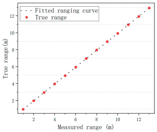
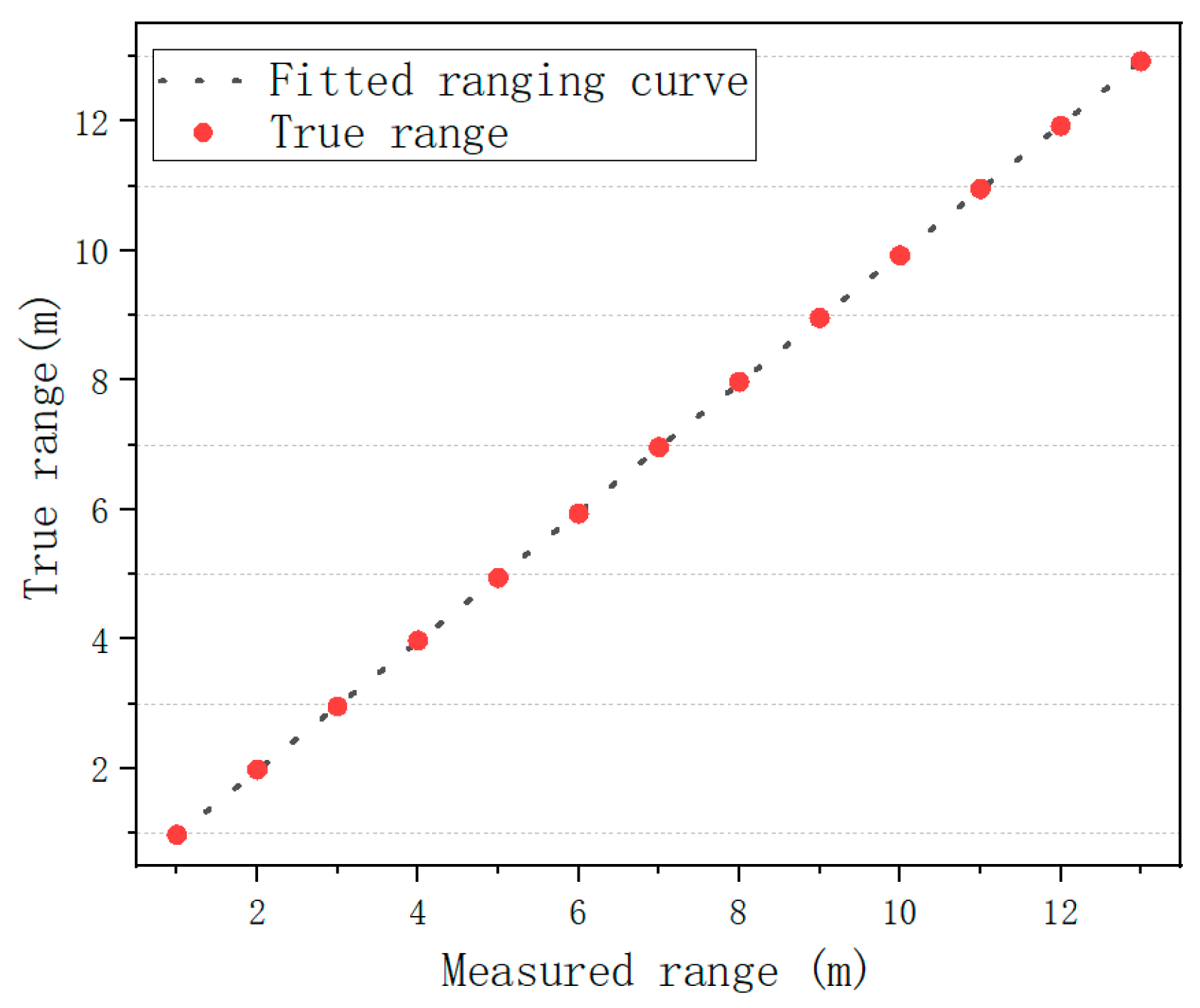
The UWB utilized in this article is the Mini 5-SMA; its main technical specifications are listed in Table 1. It achieves a maximum communication distance of 80 m and operates at a spectral range from 3.5 GHz to 6.5 GHz. The anchors and tags were deployed in an unobstructed open environment to guarantee LOS propagation conditions. All devices were fixed on adjustable brackets and precisely calibrated at an identical height of 1.5 m. We shifted the tag at 2 m intervals and adopted an electronic total station for ranging calibration, guaranteeing linear growth in the distances between tags and anchors. A total of 200 sets of ranging measurements were collected at each test position. Measurements contaminated by gross errors were eliminated in accordance with the 3σ criterion, and the average of valid observations was calculated as the calibrated raw value. The fitted correction curve is shown in Figure 1.
Table 1.
Main technical parameters of the Mini 5-SMA UWB module.
Figure 1.
Fitted ranging correction curve for UWB modules.
The expression of the correction curve is given by Equation (1).
where denotes the raw ranging measurements between UWB anchors and tags, which are confined to the ranging calibration interval; represents ranging values after calibration.
For the UWB system, the ranging error between the tag and anchor increases as the distance grows. Therefore, in practical deployments, the UWB system should avoid operating close to its maximum ranging limits.
2.2. Calibration Procedure of IMU Module
IMU hardware errors fall into two categories: deterministic errors and stochastic errors. Deterministic errors can be calibrated and compensated, primarily including bias errors and scale factor errors. Bias errors constitute a prominent fundamental error source of IMUs. Originating from hardware manufacturing limitations. Specifically, such biases appear as non-zero offsets in accelerometer and gyroscope readings even when the IMU is kept fully stationary with gravity disturbance removed. Caused by sensor fabrication tolerances, component assembly misalignment, and intrinsic hardware defects, these biases behave as fixed constant offsets. As for scale factor errors of IMUs, their essential feature is the fixed scaling mismatch between the measured accelerations/angular velocities from inertial sensors and the true kinematic quantities of the host platform. This mismatch directly impairs measurement accuracy and linearity during dynamic motion.
The IMU module adopted in this paper is the H30 model manufactured by WHEELTEC Co., Ltd., Dongguan City, China. The zero-bias calibration and compensation was conducted via the following experimental procedure. We mounted the IMU module on a six-degree-of-freedom (6-DOF) turntable. The X, Y, and Z sensitive axes were individually aligned with the gravitational direction by rotating the turntable. For both the positive and negative directions of each axis, 300 groups of acceleration data were collected, and the corresponding average values were calculated as the calibration observations. For a stationary IMU, the theoretical acceleration of each sensitive axis is equal to the local gravitational acceleration, which was set to a standard value of 9.8066 m/s2 in this study. Similarly, 300 sets of angular velocity data were acquired for each axis under static conditions, and the average values were calculated for calibration. As the IMU remained stationary during the entire data acquisition process, the obtained average values were regarded as the zero-bias errors of the gyroscope. The zero-bias error compensation results of the accelerometer and gyroscope are summarized in Table 2 and Table 3, respectively.
Table 2.
Zero-bias error compensation results of the accelerometer.
Table 3.
Zero-bias error compensation results of IMU gyroscope.
To calibrate for gyroscope scale factor errors, a 6-DOF turntable is driven to achieve uniform rotation about each of the three sensitive axes with a series of predefined reference angular rates. A total of 300 angular rate samples are acquired per axis, whose arithmetic mean serves as the raw measured angular rate for calibration. Subsequently, individual linear fitting is performed to calibrate for the scale factor errors of the X, Y, and Z-axis gyroscopes, with the derived fitting relation provided in Equation (2).
where , , and denote the calibrated X, Y, and Z-axis angular velocities of the gyroscope, while , , and represent the average angular velocities along the X, Y, and Z axes prior to calibration, respectively.
3. Implementation Process of the IR-AEKF
3.1. Construction of State Vector and System Equation
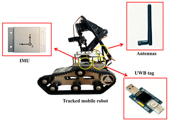
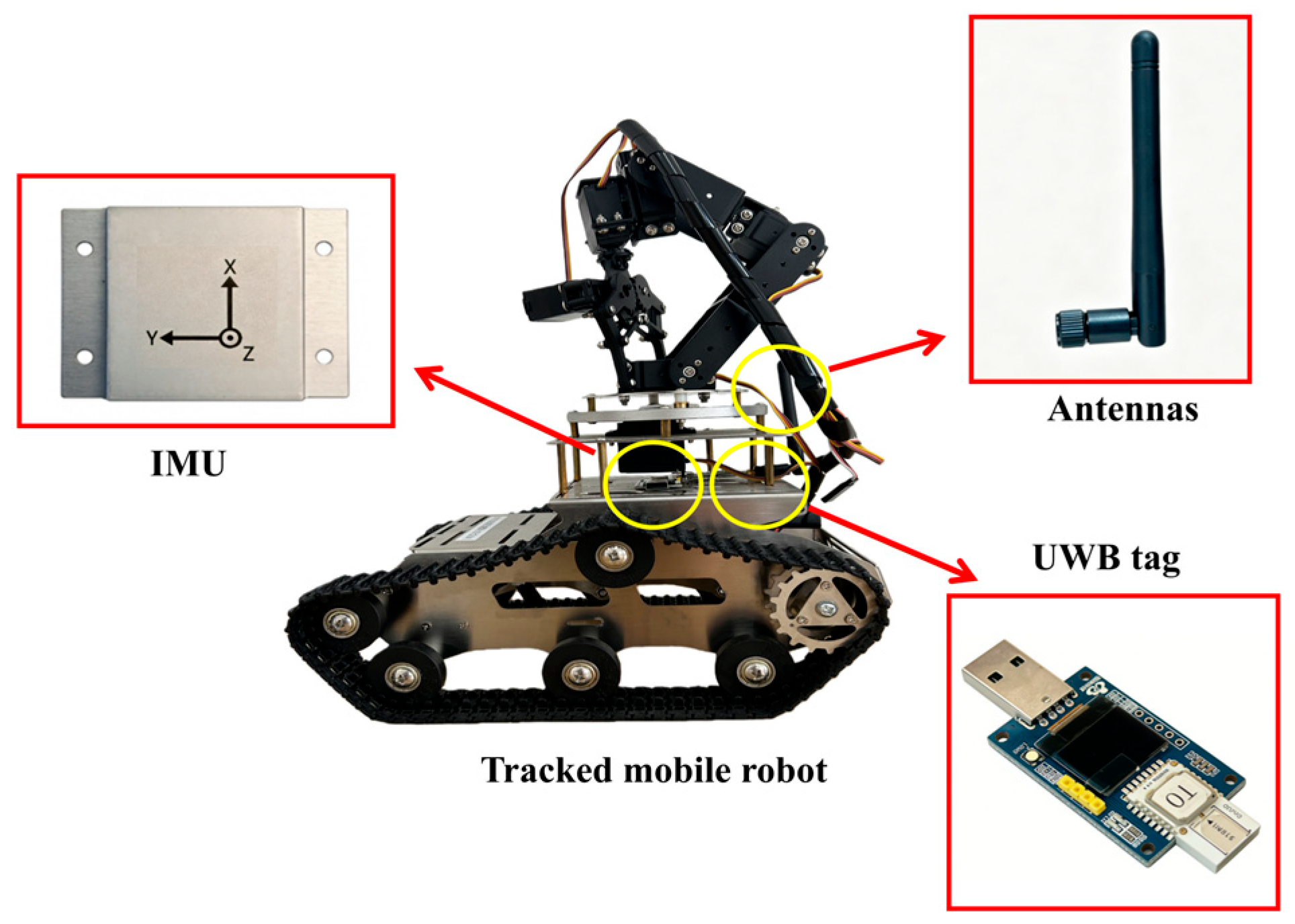
In indoor positioning scenarios, it is essential to establish the mapping transformation between the body coordinate system (BCS) and the navigation coordinate system (NCS). Accordingly, in view of the kinematic attributes of the tracked mobile robot (TMR), we define the BCS (X,Y,Z) such that the X-axis points along the TMR’s forward direction, the Y-axis points to the right side of the vehicle body, and the Z-axis is orthogonal to the horizontal plane. The NCS complies with the right-hand rule and is denoted as (x,y). For planar indoor environments, the pitch and roll angles of the TMR are deemed negligible; thus, only the heading error is retained for consideration. The IMU and UWB tag are mounted on the TMR, as illustrated in Figure 2.
Figure 2.
IMU and UWB tag layout on TMR.
The IMU measures the triaxial acceleration and angular velocity of the TMR expressed in the BCS. Under the indoor planar motion assumption, the state vector is defined as:
where denotes the coordinates of the TMR in the NCS; and represent its translational velocity components along the X and Y-axis of the NCS, respectively; is defined as the heading angle of TMR; and denote the X and Y-axis zero-bias of the IMU accelerometer, respectively, and characterizes the Z-axis zero-bias of the IMU gyroscope.
The rotation matrix from the BCS to NCS is expressed by Equation (4).
The X and Y-axis acceleration components and in the NCS can be derived from Equation (5).
where and represent the IMU acceleration in the BCS, and and denote the zero-mean white noises of the accelerometer along its X and Y axes, respectively.
A kinematic model with a sampling period of is constructed, and the state update process is given by Equation (6).
where , and denote unbiased random process noise.
3.2. UWB Ranging Model
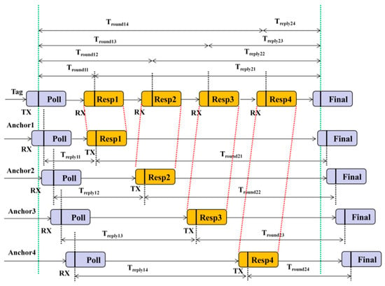
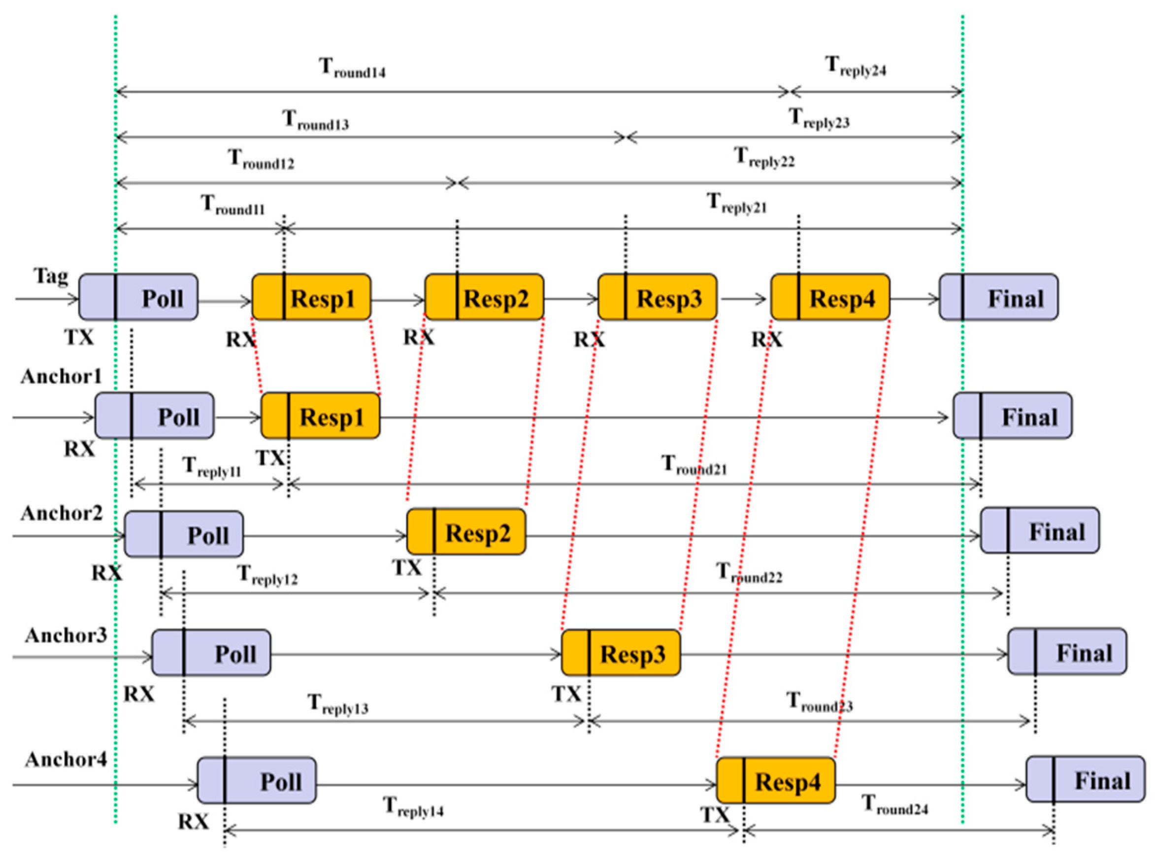
The UWB positioning subsystem consists of multiple anchors and tags. By measuring the range observations between each anchor and target tag, the system calculates the tag’s coordinates via spatial geometric constraints, thereby enabling target localization [21]. This paper employs the double-sided two-way ranging (DS-TWR) mechanism. The timing diagram and operating principle of the DS-TWR scheme are illustrated in Figure 3. In the ranging procedure, the target tag interacts with each anchor to transmit and receive UWB signal frames and fully records the timestamps of two full signal round-trip transmissions. This mechanism can effectively mitigate the timing errors caused by the inherent clock bias of UWB transceivers. Compared with the single-sided two-way ranging (SS-TWR) method, the DS-TWR mechanism exhibits a superior performance in suppressing clock-induced ranging errors [22].
Figure 3.
Timing diagram of DS-TWR scheme.
Suppose the coordinate of the anchor in the NCS is , after performing compensation for the vertical offset along the Z-axis between the anchor and the tag, the distance between the anchor and the target tag can be expressed as Equation (7).
where denotes the ranging noise. For LOS scenarios, . Under NLOS scenarios, follows a Gaussian mixture distribution that jointly accounts for multipath fading noise and outlier noise. The true Euclidean distance between anchor and the target tag is defined as .
Accordingly, the nonlinear observation equation at time instant k can be expressed as Equation (8).
where .
Meanwhile, the Jacobian matrix of Equation (6) is given in Equation (9).
3.3. Adaptive Adjustment of Noise Covariance Based on Innovation Statistics
The EKF is derived on the premise that the system process noise and measurement noise obey zero-mean Gaussian distributions. EKF linearizes nonlinear mappings through Taylor series expansion by discarding high-order terms, such that the nonlinear state-space model can be approximated. However, in the conventional EKF framework, the measurement noise covariance matrix is preset as a fixed diagonal matrix and cannot be dynamically updated according to real-time ranging quality. When UWB ranging observations are contaminated by frequent LOS/NLOS switching and gross outliers, the statistical properties of measurement noise will diverge from the preset model, which directly leads to mismatched filter gains. Moreover, conventional EKF contains no robust constraints based on innovation statistics and is devoid of innovation-driven adaptive tuning strategies, severely impairing the positioning system’s robustness. Within the extended Kalman filter (EKF) framework, this work formulates standardized innovation statistics. We assign distinct weights to each statistic and introduce an adaptive factor, which enables dynamic matching between measurement noise covariance and actual noise levels, thereby improving the anti-disturbance performance of the filtering algorithm.
The positioning system conducts state recursion sequentially driven by IMU outputs. The predicted state, predicted covariance, and state Jacobian matrix at time instant t + 1 can be sequentially derived, as expressed in Equation (10).
where denotes the nonlinear state transition function; represents the control input vector, which acts as the driving term for state recursion and participates directly in state prediction computation, formulated as ; denotes the process noise following a zero-mean Gaussian distribution, i.e., ; stands for the state Jacobian matrix, which enables local linearization of the nonlinear state equation to implement error propagation calculation; denotes the covariance matrix of process noise.
After acquiring the UWB ranging measurement at time k, we construct the innovation vector and the state Jacobian matrix associated with the observation function via the nonlinear observation equation, as formulated in Equation (11).
In Equation (11), denotes the innovation vector that characterizes the residual between actual observations and filter prior predictions and quantifies the model estimation bias. Under ideal conditions, the mean of the innovation sequence converges to zero. represents the observation Jacobian matrix, which captures the mapping sensitivity between system state variables and observations. In practical filtering iterations, and are jointly employed to correct the prior state estimates of the positioning system.
In the Kalman gain update step of EKF, the measurement noise covariance matrix is generally predefined as a constant diagonal positive definite matrix. Such a fixed-parameter assumption cannot adapt to real-time dynamic variations in sensor noise. If the elements of this matrix are set to large values, the weight of measurement information will be suppressed during filter updates. On the contrary, small matrix values will make the algorithm overly dependent on measurement data and significantly degrade the system’s anti-disturbance performance. For the UWB/IMU fusion positioning system, both ranging measurements and IMU outputs may contain outliers. Utilizing the above constant noise covariance assumption will markedly deteriorate the robustness of the positioning system. To overcome this drawback, we derive a measurement update procedure for an improved AEKF, whose formula is presented in Equation (12).
where denotes the Kalman gain, which weights the contributions of state model predictions and sensor measurements. represents the adaptive observation noise covariance matrix, a diagonal matrix whose diagonal entry satisfies , wherein denotes the calibrated ranging variance of the UWB under LOS conditions. stands for the Huber weighting factor, which can be calculated via Equation (13).
where denotes the component of the innovation vector, characterizes the variance of this innovation component, and represents an empirical threshold with a reasonable value range of . In addition, an empirical range-gating threshold is introduced. If the discrimination criterion is satisfied, the corresponding range measurement will be discarded.
As derived from Equation (13), assigns a full weight of 1 to measurements with small residuals. For outlier measurements whose residuals exceed the predetermined threshold, the weight decays continuously with the growth of residual amplitude and never equals zero. This weighting scheme can completely retain valid observation information and significantly alleviate the adverse influence of gross errors and outlier measurements on the iterative process of UWB/IMU fusion filtering. Compared with the EKF, the proposed algorithm delivers stronger resistance to real-time noise perturbations and effectively improves the overall robustness of the localization system. Furthermore, to capture the temporal variation of overall noise levels, the final adaptive observation noise covariance matrix adopted in this work is provided in Equation (14).
where denotes the innovation covariance matrix and represents the adaptive coefficient satisfying .
In summary, the implementation procedure of the IR-AEKF algorithm is outlined in Table 4.
Table 4.
Main steps of IR-AEKF algorithm.
4. Experiments and Analysis
4.1. Experimental Facilities and Test Environment
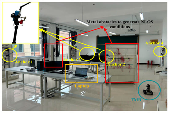
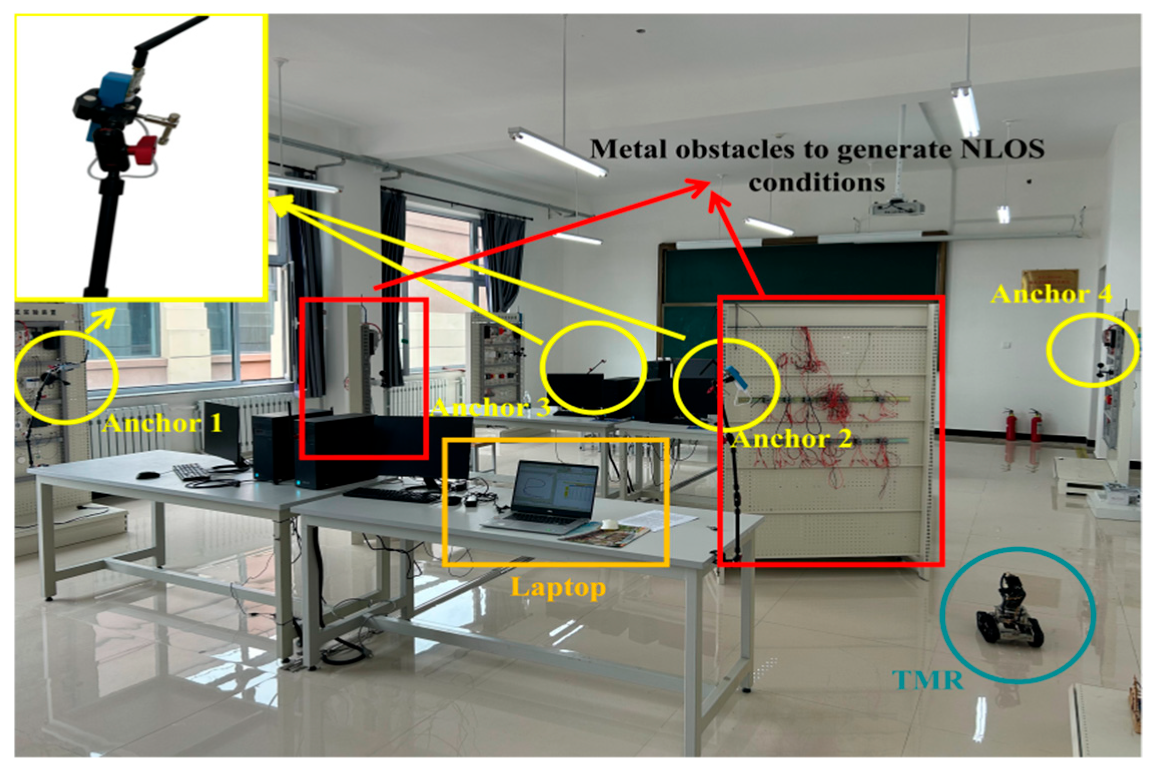
The experiments were conducted in a laboratory at the south campus of Shenyang Institute of Technology, as illustrated in Figure 4. The laboratory had a specific geometry of 8 m × 16 m. Several metal experimental benches were placed within the space to create NLOS propagation conditions. In consideration of the actual site dimensions, four anchors labeled 1, 2, 3, and 4 were deployed. Their coordinates are , , , and , respectively. The position dilution of precision (PDOP) constitutes a key metric for evaluating the deployment of UWB systems [23,24]. To optimize the PDOP, the following principles should be adopted for anchor deployment:
Figure 4.
On-site experiment scenario.
- (1)
- Anchors should be deployed in a non-coplanar configuration. Specifically, at least one anchor lies outside the plane spanned by the remaining anchors (e.g., employing high-low mounting).
- (2)
- Anchors should preferably surround the tag rather than be arranged on a single side to enhance the diversity of constraints.
- (3)
- Additional anchors can be deployed according to indoor spatial dimensions, which reduces reliance on unidirectional observations and improves UWB system’s robustness against measurement errors and multi-path effects.
A UWB tag and an IMU module were mounted on the TMR for multi-sensor data acquisition. The UWB subsystem was configured via the host computer, where Anchor 1 was configured as the primary station and the remaining anchors were set as secondary stations. For the UWB subsystem, the center operating frequency was set to 5 GHz, with the operating frequency band ranging from 3.5 GHz to 6.5 GHz. In terms of network communication configurations, the target IP address and data transmission port of the UWB subsystem were configured as 192.168.10.200 and 3000, respectively, and the communication channel rate was set to 10 kbps. Additionally, 3010 was designated as the exclusive data transmission port for UWB tag. Prior to formal data acquisition, pre-calibration of both UWB and IMU was performed in accordance with the steps specified in Section 2. Owing to the higher sampling rate of the IMU sensor compared with the UWB subsystem, rigorous clock synchronization cannot be maintained between these two sensoring systems. Such timestamp misalignment introduces temporal errors and deteriorates the fused positioning accuracy. In the experiments, the sampling rate of the UWB subsystem is selected as the reference clock for data fusion, and the IMU sampling rate is set to times the UWB sampling rate. The proposed UWB/IMU data fusion matching mechanism is detailed as follows. First, a judgment threshold is defined for fusion validity assessment. At each data fusion epoch, consecutive IMU measurements collected after the previous fusion epoch are grouped into a single computation block. Next, the timestamp offset between this IMU computation block and the current fusion epoch is calculated. The fused data are deemed valid if ; otherwise, the corresponding fused positioning solution is discarded.
4.2. Static Positioning Experiment and Analysis
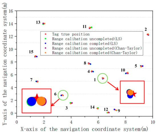
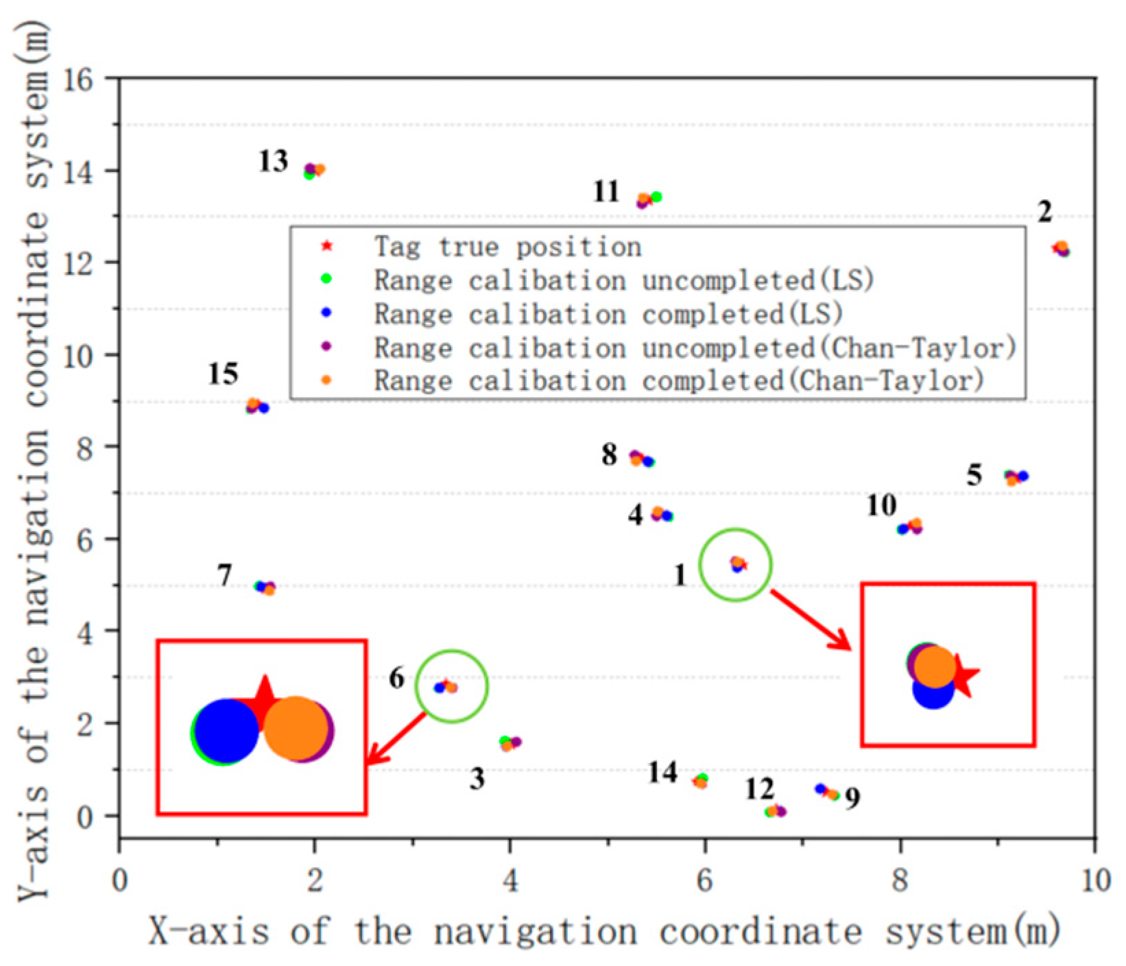
To validate the performance of UWB ranging calibration, fifteen test points were randomly deployed in the experimental area. The coordinates of these test points were measured with a total station and a rangefinder and serve as the ground truth. Subsequently, the tracked mobile robot was controlled to precisely align the tag with each test point. At each test point, ranging data were sampled by the host computer for 3 s. We adopt the least squares (LS) and Chan-Taylor algorithms for comparison and conduct stochastic positioning experiments via the Monte Carlo method. Among them, LS is an analytical algorithm, while Chan-Taylor belongs to classical fused analytical and iterative algorithms that can effectively evaluate the positioning performance of the UWB subsystem. The positioning results are presented in Figure 5.
Figure 5.
Comparison of UWB positioning results.
As analyzed from Figure 5, the ranging and positioning accuracy of the UWB subsystem is improved after ranging calibration. This accuracy gain holds for both analytical and iterative positioning algorithms. Detail positioning data are listed in Table 5.
Table 5.
Positioning error with uncompleted and completed ranging calibration.
In the adaptive adjustment process of the IR-AEKF algorithm, the Huber weighting factor is jointly determined by the scalar component of the innovation vector , and the empirical threshold . For measurements with small-magnitude , the corresponding diagonal element is amplified, which automatically reduces their contribution to Kalman gain. To characterize the effects of threshold parameters and on the positioning accuracy of IR-AEKF, test points 5 and 7 were randomly selected, and 500 positioning trials were carried out for each threshold configuration. Representative experimental statistics are listed in Table 6. The results reveal that and exert discernible impacts on the positioning performance of IR-AEKF under both LOS and NLOS scenarios. Variations in and lead to fluctuations in positioning accuracy, alongside the volume of discarded ranging measurements. Specifically, as decreases, the number of discarded ranging measurements increases. In the LOS scenario, the ID 5 achieves optimal positioning accuracy under and , with a mean positioning error of 0.037 m and a maximum positioning error of 0.070 m. Under identical threshold settings, ID 7 yields the optimal positioning performance in the NLOS condition, with average and maximum positioning errors of 0.061 m and 0.082 m, respectively. The experimental results indicate that a small magnitude enables filtering of ranging measurements. However, excessively strict threshold conditions degrade positioning accuracy and may even lead to a positional blind zone. Therefore, it is necessary to strike a trade-off between ranging measurement quantity and positioning accuracy. In the subsequent experiments, the IR-AEKF algorithm is employed with and . Test points 5 and 7 are only utilized as the parameter-tuning dataset determines threshold hyperparameters. These two test points are excluded from the final static performance evaluation.
Table 6.
Effects of Threshold Parameters on Positioning Accuracy and Data Filtered for IR-AEKF Algorithm.
To validate the positioning performance of the proposed algorithm (denoted as UWB/IMU-IR-AEKF), we conducted comparative experiments against the EKF (denoted as UWB/IMU-EKF), AEKF (denoted as UWB/IMU-AEKF), LS (denoted as UWB-LS), and Chan-Taylor (denoted as UWB-Chan-Taylor) algorithms. Additionally, to facilitate a comprehensive comparison, we adopted the improved variants of the aforementioned classical algorithms, including those reported in [14] (denoted as UWB/IMU-GMC-VKBS-EKF), Ref. [15] (denoted as UWB/IMU-MC-UKF), and [18] (denoted as UWB/IMU-LSSVM-AEKF). The LS and Chan-Taylor algorithms achieve positioning by relying solely on the standalone UWB subsystem. Built on the EKF framework consisting of state prediction, measurement update, and Jacobian linearization, the AEKF integrates a Sage-Husa adaptive module utilizing the innovation sequence to recursively update the measurement noise covariance matrix. However, it does not adopt Huber-based weight updating or outlier rejection mechanisms. The approach in [14] employs clustering and outlier detection for raw UWB ranging measurements. It uses a sliding window to detect NLOS anomalies, defines a kernel bandwidth and a tunable maximum correntropy criterion, and incorporates them into EKF. Ref. [15] develops a tightly coupled robust unscented Kalman filter (RUKF) localization framework based on maximum correntropy. Within this framework, adaptive updates of the UWB measurement noise matrix and dynamic tuning of UWB observation weights are implemented. Ref. [18] introduces the Sage-Husa adaptive factor to preprocess UWB ranging measurements. The whale optimization algorithm (WOA) is then used to optimize the parameters of the least squares support vector machine (LSSVM) model, which is subsequently employed to compensate for systematic errors. Compared with the algorithms in the aforementioned literature, the IR-AEKF exploits innovation statistics to simultaneously introduce Huber weights and an adaptive scaling factor for dynamically adjusting the observation noise covariance. A ranging outlier rejection mechanism is additionally devised, which eliminates the requirement for cumbersome kernel parameter optimization and machine learning model training. The mean and maximum position errors yielded by all involved algorithms are listed in Table 7.
Table 7.
Positioning Error of Various Algorithms under Static Conditions.
As shown in Table 7, under static NLOS and LOS scenarios, these improved algorithms deliver further enhanced positioning accuracy relative to conventional EKF and AEKF. By indirectly compensating model errors through adaptive terms, AEKF and its variants are better suited for positioning scenarios with high noise levels. Experimental results indicate that IR-AEKF algorithm achieves superior positioning accuracy compared with GMC-VKBS-EKF, MC-UKF, and LSSVM-AEKF. This demonstrates that the Huber-based weight allocation and ranging outlier elimination mechanism adopted in IR-AEKF can effectively mitigate the disturbances stemming from gross errors and abnormal ranging data to filtering computation. Furthermore, experimental validations show that the UWB/IMU fusion system exhibits better positioning performance than the standalone UWB system (i.e., LS and Chan-Taylor).
To clarify the individual contributions and synergistic gains of each core module within the IR-AEKF algorithm, static ablation experiments were conducted, where the original dataset containing 15 static test points, complete UWB and IMU calibration results, and system model remained unchanged. Seven algorithm variants were constructed by enabling or disabling individual modules: Huber-type weighting only, outlier rejection only, adaptive covariance update only, the combination of Huber-type weighting and outlier rejection, the combination of Huber-type weighting and adaptive covariance update, the combination of outlier rejection and adaptive covariance update, and the IR-AEKF integrating all three modules. The conventional AEKF was adopted as the baseline for comparison. Batch evaluations were performed on static positioning datasets under mixed LOS/NLOS conditions. For each variant, the 2D mean and maximum positioning error were computed and listed in Table 8. Taking the positioning error of the baseline AEKF as the reference, the positioning accuracy improvements brought by each standalone module and their combinations were quantified.
Table 8.
Static positioning results of ablation experiments for IR-AEKF.
Static ablation results demonstrate that Huber-type weighting, outlier rejection, and adaptive covariance update individually enhance positioning accuracy. Noticeable synergistic gains emerge when multiple modules are combined, and the IR-AEKF incorporating all modules yields the optimal positioning performance.
4.3. Dynamic Positioning Experiment and Analysis
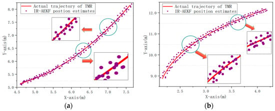
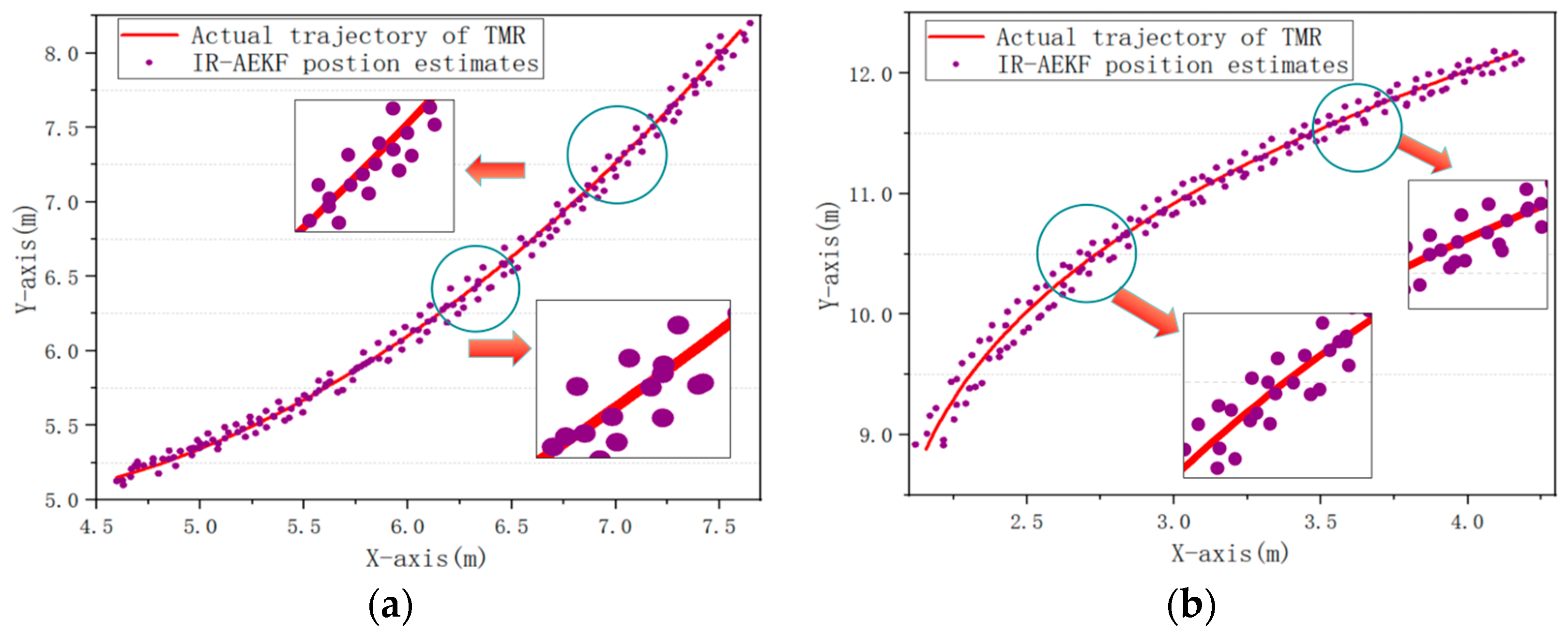
In dynamic experiments, the reference ground truth trajectory for the TMR was acquired by an auto-tracking total station. It should be noted that the native sampling frequency of the total station is lower than the sampling rates of UWB and IMU sensors. Therefore, cubic spline interpolation is applied to resample raw total-station outputs, mapping ground-truth coordinates onto the identical time-axis of UWB/IMU filter outputs. Precise timestamp alignment among multi-sensor datasets is completed in post-processing. The time synchronized coordinate sequence after interpolation serves as the ground truth reference for quantitative positioning error evaluation in all dynamic tests. Importantly, this dynamic trajectory dataset is fully independent and does not reuse any samples from static parameter-tuning or static-test datasets. We employ the same UWB anchor deployment scheme as that used for static tests. To reproduce realistic indoor positioning conditions, the TMR is controlled to conduct variable-speed movements with random velocity adjustments. The TMR undergoes several steering, acceleration, and deceleration maneuvers during the test. Comparative results are presented in Figure 6.
Figure 6.
Positioning results of the IR-AEKF algorithm under dynamic conditions: (a) Partial example 1. (b) Partial example 2.
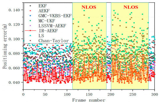
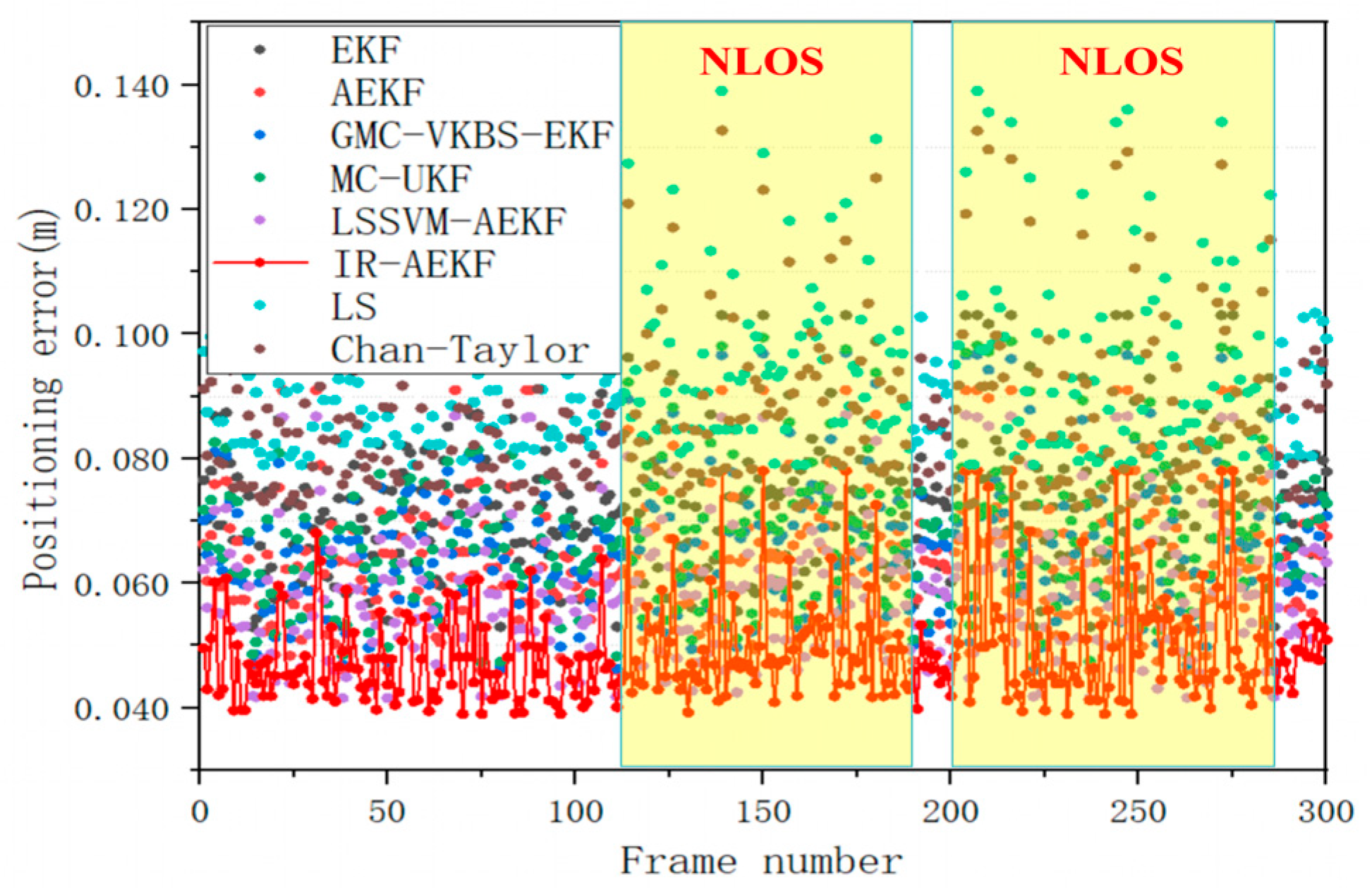
As shown in Figure 6, IR-AEKF can continuously deliver stable position estimates for the TMR under dynamic conditions and achieve reliable trajectory tracking performance. 300 consecutive positioning samples are randomly chosen, with which different positioning algorithms are used for TMR localization. The results are illustrated in Figure 7.
Figure 7.
Comparison of positioning errors under dynamic conditions.
Under dynamic conditions, remarkable differences are observed in the trajectory performance of the TMR with the six positioning algorithms: GMC-VKBS-EKF, MC-UKF, LSSVM-AEKF, IR-AEKF, LS, and Chan-Taylor. As can be seen from Figure 7, the LS and Chan-Taylor algorithms yield evidently inferior positioning accuracy relative to other approaches. This indicates that the UWB/IMU integrated positioning system achieves better performance than the standalone UWB system under dynamic conditions. During the whole experiment, although GMC-VKBS-EKF and MC-UKF are capable of closely tracking the real trajectory of the TMR, considerable deviations arise in NLOS regions. In comparison, LSSVM-AEKF and IR-AEKF exhibit superior adaptability to NLOS scenarios. This demonstrates that the framework with an adaptively tuned measurement noise covariance matrix can suppress NLOS-induced errors. Among all the compared algorithms, IR-AEKF delivers the highest positioning accuracy. Overall, owing to the synergistic mechanism combining the Huber cost function strategy and the elimination of abnormal ranging measurements, IR-AEKF effectively suppresses the interferences caused by gross errors and faulty ranging data.
The statistical results of positioning errors are presented in Table 9. The IR-AEKF maintains relatively steady fluctuations in X-axis and Y-axis positioning errors. Its mean positioning errors along the X and Y axes reach 0.032 m and 0.035 m, respectively. In comparison with the conventional AEKF, the positioning accuracy is enhanced by 25.58% and 23.91%.
Table 9.
Positioning Error Statistics under Dynamic Conditions.
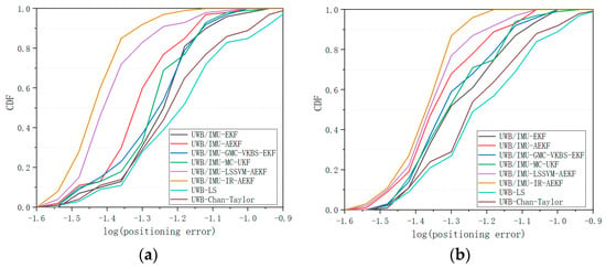
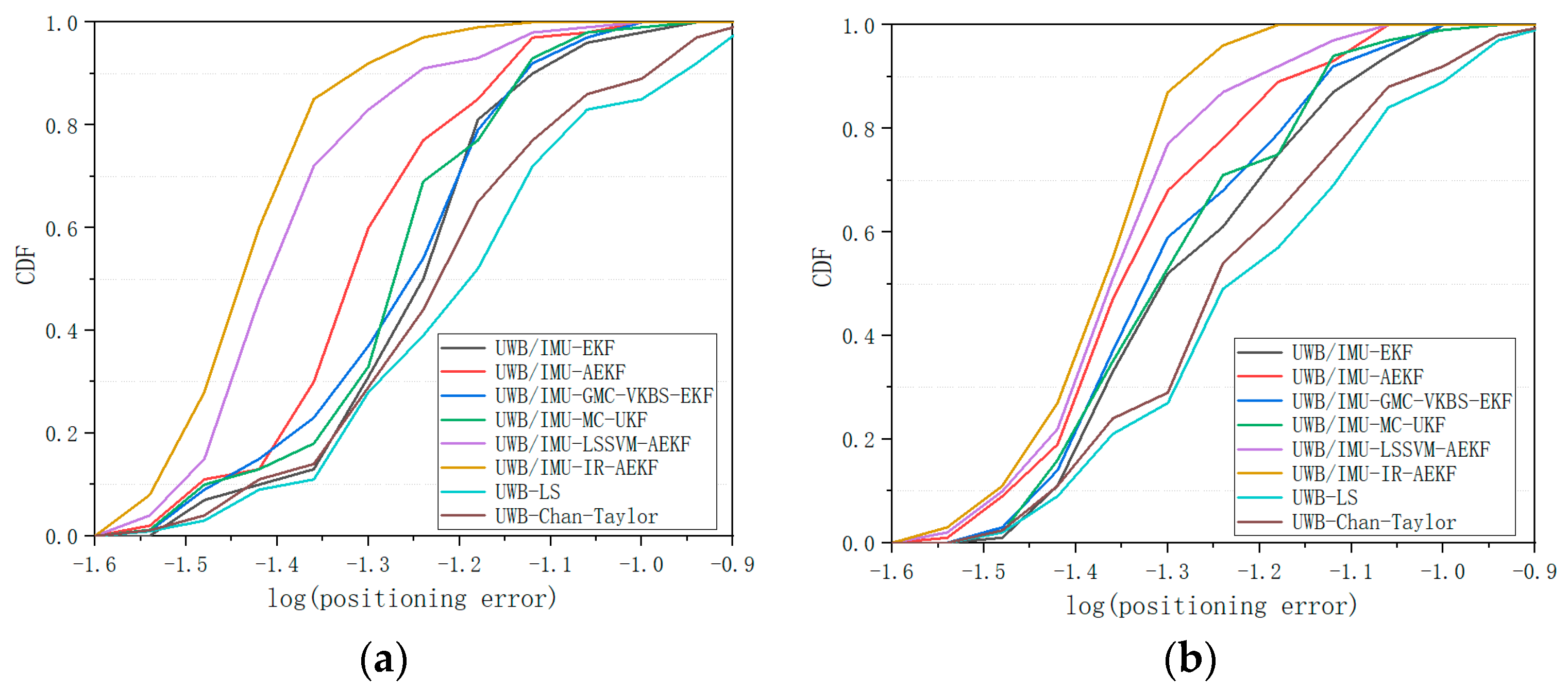
Simulation experiments are conducted on the MATLAB 2021a platform with measured UWB ranging data and IMU measurements. Cumulative distribution function (CDF) curves of positioning errors are plotted separately under LOS and NLOS conditions, as illustrated in Figure 8. The CDF curve corresponding to the IR-AEKF algorithm presents a steeper rising trend in comparison with the GMC-VKBS-EKF, MC-UKF, LSSVM-AEKF, and the standalone UWB positioning algorithms. This phenomenon demonstrates that the IR-AEKF accumulates the majority of probability mass within a small error interval and achieves superior system robustness. It further verifies that the IR-AEKF can effectively adapt to NLOS environments and complex positioning scenarios.
Figure 8.
Comparison of CDF curves: (a) CDF curves in LOS scenarios. (b) CDF curves in NLOS scenarios.
4.4. Execution Duration Analysis of IR-AEKF
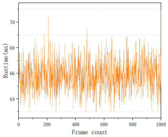
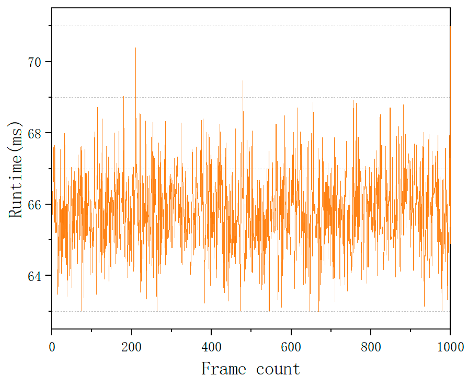
To evaluate the computational stability of the proposed method, 1000 consecutive positioning frames were sampled during operation of the host platform. The end-to-end processing latency of the entire workflow, encompassing UWB and IMU data acquisition, time synchronization, and filter computation, was recorded frame-by-frame. As shown in Figure 9, the single-step positioning latency ranges from 63 ms to 71 ms, with an average latency of 65.8 ms. This demonstrates that the IR-AEKF exhibits minor fluctuations in computational load and can sustain stable real-time performance.
Figure 9.
Running time of the IR-AEKF.
5. Conclusions
The advent of IoT has driven explosive growth in the demand for centimeter-level positioning from individuals and enterprises. Since the GNSS fails to provide accurate position information in indoor environments, developing precise and robust indoor positioning technologies is vital to overcome GNSS limitations in application scenarios. At present, the UWB/IMU fusion positioning method has been applied. Nevertheless, frequent transitions between LOS and NLOS conditions, alongside the lack of an adaptive tuning mechanism for innovation covariance, degrade positioning accuracy and robustness.
To address aforementioned issues, this article establishes a tightly coupled UWB/IMU positioning model for complex indoor scenarios and proposes the IR-AEKF positioning algorithm. After calibrating UWB ranging errors, IMU bias, and scale factor errors, the system state equation and UWB ranging observation model are constructed under the tightly coupled fusion framework. On this basis, innovation statistics are leveraged to incorporate Huber-type weights and adaptive scaling factors that dynamically tune the observation noise covariance matrix. Meanwhile, a ranging outlier elimination threshold is set to suppress gross errors induced by NLOS interference. Experimental results demonstrate that IR-AEKF effectively mitigates gross errors and abnormal ranging disturbances triggered by LOS/NLOS transitions. In dynamic scenarios, the average positioning errors along the X-axis and the Y-axis reach 0.032 m and 0.035 m, respectively. The proposed algorithm offers crucial insights into UWB/IMU fusion positioning and shows promising practical application prospects.
Author Contributions
Methodology, Z.L. (Zhenyu Liu); writing—review and editing, Z.L. (Zhiqi Li); funding acquisition, Z.L. (Zhenyu Liu). All authors have read and agreed to the published version of the manuscript.
Funding
This research was funded by the Applied Basic Research Project of Liaoning Province, China, grant number 2023JH2/101200225, and the Liaoning Provincial Natural Science Foundation Robot Joint Fund, grant number 20180520022, and the Basic Research Project of Liaoning Provincial Department of Education, grant number LJ222410142060 and LJ212513621005.
Data Availability Statement
The program of the positioning algorithm in this study is available upon reasonable request.
Conflicts of Interest
The authors declare no conflicts of interest.
References
- Bastiaens, S.; Alijani, M.; Joseph, W.; Plets, D. A Review of the Quality of Positioning Service of VLP within the Indoor Positioning System Landscape. IEEE Trans. Instrum. Meas. 2026, 75, 1–33. [Google Scholar] [CrossRef] [Scilit]
- Zhou, B.; Wu, P.; Zhang, X.; Zhang, D.; Li, Q. Activity Semantics-Based Indoor Localization Using Smartphones. IEEE Sens. J. 2026, 24, 11069–11079. [Google Scholar]
- Yao, H.; Liang, X.; Chen, R.; Wang, X.; Qi, H.; Chen, L.; Wang, Y. A Benchmark of Absolute and Relative Positioning Solutions in GNSS Denied Environments. IEEE Internet Things J. 2024, 11, 4243–4273. [Google Scholar] [CrossRef] [Scilit]
- Yao, H.; Qu, X.; Wu, L.; Wu, Y. Vehicle Cooperative Localization Based on UWB Technology in GNSS-Denied Environments. IEEE Sens. J. 2026, 25, 34882–34893. [Google Scholar] [CrossRef] [Scilit]
- Qin, Z.; Meng, Z.; Li, Z.; Gao, N.; Zhang, Z.; Meng, Q.; Zhen, D. Compensating the NLoS Occlusion Errors of UWB for Pedestrian Localization with MIMU. IEEE Sens. J. 2023, 23, 12146–12158. [Google Scholar] [CrossRef] [Scilit]
- Qi, L.; Zhao, Y.; Guo, Q.; Kaliuzhnyi, M.; Wang, E. Deep Learning-Based NLOS Identification of UWB Signals. IEEE Signal Process. Lett. 2025, 32, 2394–2398. [Google Scholar] [CrossRef] [Scilit]
- Yang, X.; Zhao, F.; Chen, T. NLOS Identification for UWB Localization Based on Import Vector Machine. Int. J. Electron. Commun. 2018, 87, 128–133, Correction in Int. J. Electron. Commun. 2020, 113, 152948. [Google Scholar] [CrossRef] [Scilit]
- Liu, Z.; Li, Z. NLOS Mitigation and Indoor Positioning Method Based on UWB Ranging. IEEE Sens. J. 2025, 25, 43372–43381. [Google Scholar] [CrossRef] [Scilit]
- Wang, Q.; Li, Z.; Zhang, H.; Yang, Y.; Meng, X. An Indoor UWB NLOS Correction Positioning Method Based on Anchor LOS/NLOS Map. IEEE Sens. J. 2023, 23, 30739–30750. [Google Scholar] [CrossRef] [Scilit]
- Yang, H.; Wang, Y.; Seow, C.K.; Sun, M.; Coene, S.; Huang, L.; Joseph, W.; Plets, D. Fuzzy Transformer Machine Learning for UWB NLOS Identification and Ranging Mitigation. IEEE Trans. Instrum. Meas. 2026, 74, 1–17. [Google Scholar] [CrossRef] [Scilit]
- Zhong, L.; Xu, X.; Yao, Y.; Zhang, T. A Self-Alignment Method for Vehicle-Mounted MEMS IMU. IEEE/ASME Trans. Mechatron. 2026, 31, 3154–3166. [Google Scholar] [CrossRef] [Scilit]
- Huang, F.; Wang, Z.; Xing, L.; Gao, C. A MEMS IMU Gyroscope Calibration Method Based on Deep Learning. IEEE Trans. Instrum. Meas. 2022, 71, 1–9. [Google Scholar] [CrossRef] [Scilit]
- Wouda, F.J.; Sakthivelu, U.; Bilal, I. Analyzing Gait with Minimal Body-Worn Sensing: Combining UWB and IMU. IEEE Sens. J. 2025, 25, 29454–29461. [Google Scholar] [CrossRef] [Scilit]
- Qu, J.; Yuan, Y.; Shen, F.; Li, W.; Sun, H. A Generalized Maximum Correntropy Extended Kalman Filter for UWB/IMU Localization. IEEE Sens. J. 2025, 24, 36267–36280. [Google Scholar] [CrossRef] [Scilit]
- Li, X.; Ye, J.; Zhang, Z.; Fei, L.; Xia, W.; Wang, B. A Novel Low-Cost UWB/IMU Positioning Method with the Robust Unscented Kalman Filter Based on Maximum Correntropy. IEEE Sens. J. 2024, 24, 29219–29231. [Google Scholar] [CrossRef] [Scilit]
- Sui, X.; Liao, B.; Wang, C.; Shi, Z. Improved XGBoost and GM UWB/MEME IMU Positioning Methods for Non-Line-of-Sight Environments. IEEE Sens. J. 2024, 24, 42384–42393, Correction in IEEE Sens. J. 2025, 25, 9208. [Google Scholar] [CrossRef] [Scilit]
- Sun, J.; Sun, W.; Zheng, J.; Chen, Z.; Tang, C.; Zhang, X. A Novel UWB/IMU/Odometer-Based Robot Localization System in LOS/NLOS Mixed Environments. IEEE Trans. Instrum. Meas. 2024, 73, 1–13. [Google Scholar] [CrossRef] [Scilit]
- Wei, M.; Liu, L.; Li, S.; Wang, D.; Tang, S. UWB/IMU Integrated Positioning Technology with NLOS Mitigation: An Improved LSSVM and AEKF Fusion Strategy. IEEE Trans. Instrum. Meas. 2026, 75, 1–14. [Google Scholar] [CrossRef] [Scilit]
- Cheng, L.; Song, J.; Zhao, W. A Hybrid EKF/WUFIR Filter for Indoor Localization Integrating INS and UWB Data. IEEE Trans. Netw. Sci. Eng. 2025, 12, 2266–2276. [Google Scholar] [CrossRef] [Scilit]
- Feng, D.; Wang, C.; He, C.; Zhuang, Y.; Xia, X. Kalman-Filter-Based Integration of IMU and UWB for High-Accuracy Indoor Positioning and Navigation. IEEE Internet Things. J. 2020, 7, 3133–3146. [Google Scholar] [CrossRef] [Scilit]
- Jeon, W.S.; Oh, H.S.; Jeong, D.G. Decision of Ranging Interval for IEEE 802.15.4z UWB Ranging Devices. IEEE Internet Things. J. 2021, 8, 15628–15638. [Google Scholar] [CrossRef] [Scilit]
- Yan, R.; Wang, X.; Wang, X.; Liu, X.; Tian, Y. Train Positioning method Based on Calibrated UWB Ranging Model in Tunnel Environment. IEEE Trans. Instrum. Meas. 2025, 74, 1–11. [Google Scholar] [CrossRef] [Scilit]
- Bach, S.; Khoi, P.; Yi, S. Global UWB System: A High-Accuracy Mobile Robot Localization System with Tightly Coupled Integration. IEEE Internet Things J. 2024, 11, 16618–16626. [Google Scholar] [CrossRef] [Scilit]
- Zhang, L.; Zhang, Z.; Siegwart, R.; Chung, J.J. Distributed PDOP Coverage Control: Providing Large-Scale Positioning Service Using A Multi-Robot System. IEEE Robot. Autom. Lett. 2021, 6, 2217–2224. [Google Scholar] [CrossRef] [Scilit]

Disclaimer/Publisher’s Note: The statements, opinions and data contained in all publications are solely those of the individual author(s) and contributor(s) and not of MDPI and/or the editor(s). MDPI and/or the editor(s) disclaim responsibility for any injury to people or property resulting from any ideas, methods, instructions or products referred to in the content. |
© 2026 by the authors. Licensee MDPI, Basel, Switzerland. This article is an open access article distributed under the terms and conditions of the Creative Commons Attribution (CC BY) license.