


Abstract
Connected vehicles are mobile Internet-of-Things (IoT) nodes requiring reliable, high-capacity, low-latency vehicle-to-everything (V2X) communication for cooperative perception, safety messaging, traffic coordination, and data-intensive services. This article presents dual-side beamforming for multi-user millimeter-wave massive MIMO in V2X-IoT, targeting end-to-end beam alignment, capacity, spectral efficiency, and user fairness in challenging urban environments. A 64-element base-station array serves multiple vehicles: transmit precoding directs energy toward users, while receive combining strengthens desired signals and suppresses interference and noise. Unlike transmitter-only studies, this framework analyzes transmit–receive array interactions, evaluating beam alignment, array-response matching, and the effect of receiver processing on effective signal-to-interference-plus-noise ratio (SINR). We characterize the antenna in Ansys Electronics Desktop 2026 R1 using full-wave electromagnetic simulation, then integrate the results into Divergent Physics, an AI-driven Python RF-design environment. We evaluate multi-user beamforming, power allocation, and capacity across user locations and channel conditions, comparing Maximum Ratio Transmission (MRT), Zero-Forcing (ZF), Linear Minimum Mean Square Error (LMMSE), and fairness-oriented optimization. Dual-sided beamforming—joint BS transmit precoding and vehicle receive combining—delivers the best SINR, capacity, and spectral efficiency. Fairness-aware configurations reduce spectral efficiency across all methods by prioritizing balanced user performance. These configurations provide a scalable framework for analyzing interactions among antenna design, beamforming, vehicle deployment, and communication performance in mmWave V2X-IoT networks.
1. Introduction
Vehicular-to-everything (V2X) communication is vital to next-generation intelligent transportation systems, enabling fast, reliable, low-latency data exchange among vehicles, pedestrians, infrastructure, and cloud services. Connected vehicles act as mobile IoT nodes, sharing sensing, safety, control, and infotainment data with roadside infrastructure, other vehicles, pedestrians, and cloud or edge services. V2X-IoT must provide equitable, reliable connectivity despite diverse vehicle locations, propagation conditions, and quality-of-service needs—not merely high peak data rates. To meet the demanding throughput requirements of future connected vehicles, millimeter-wave (mmWave) communication and massive multiple-input multiple-output (MIMO) are increasingly regarded as enabling technologies, as they provide large bandwidth and strong spatial directivity through narrow-beam transmission and reception. However, the same narrow beams that make mmWave attractive also render the link highly sensitive to mobility, blockage, beam misalignment, and angular variation, which are particularly severe in urban V2X-IoT environments [1,2].
A major challenge in mmWave V2X-IoT is that the communication channel rapidly changes due to vehicle motion, surrounding traffic, and frequent occlusions. As a result, beam alignment is critical to maintaining connectivity and preventing severe performance degradation. Recent studies have investigated beam search, beam prediction, and learning-assisted alignment to reduce training overhead and improve link robustness in mobile scenarios. These studies emphasize transmitter-side beam selection or beam search, while the interaction between the transmit and receive arrays, and their combined effect on effective signal quality, is less thoroughly addressed [1,2,3,4]. In multi-user mmWave massive MIMO systems, the base station (BS) serves multiple vehicles simultaneously, often under correlated channels, unequal path strengths, and strong inter-user interference. Linear precoding methods like Maximum Ratio Transmission (MRT), Zero-Forcing (ZF), and Linear Minimum Mean Square Error (LMMSE) are still key benchmarks, as they balance beam direction, interference reduction, and complexity of implementation. At the same time, fairness-aware scheduling and optimization are necessary because users at different distances or angles can experience highly uneven rates, especially in vehicular settings where geometry changes quickly and channels are often heterogeneous [5,6,7].
This article addresses these challenges by proposing a dual-side beamforming framework for multi-user mmWave massive MIMO in V2X-IoT networks. The framework explicitly considers both transmit precoding and receive combining, enabling joint analysis of beam alignment, received power enhancement, effective signal-to-interference-plus-noise ratio (SINR), spectral efficiency, and fairness among users. The proposed methodology incorporates full-wave electromagnetic characterization of the antenna and array structure using Ansys Electronics Desktop and then embeds these results into an agent-driven workflow (Divergent Physics) for a system-level simulation environment.
This antenna-to-system integration is motivated by the fact that physical array behavior strongly influences beamforming performance at mmWave frequencies. In practice, mutual coupling, pattern distortion, and platform effects can alter the actual array response and reduce the accuracy of idealized beamforming assumptions. By capturing these effects before evaluating multi-user precoding, the article provides a more rigorous framework for studying how antenna design, beam steering, and user geometry jointly determine communication performance in V2X networks [4,8].
Cooperative vehicular IoT applications—such as collision avoidance, perception, platooning, and traffic coordination—require reliable connectivity for weak, distant, or blocked vehicles. Fairness-aware beamforming and power allocation prevent sum-rate designs from favoring nearby users while leaving critical edge or shadowed nodes with poor links. This article further considers -fairness optimization to balance performance among users experiencing different propagation conditions. This is particularly important in V2X-IoT because vehicles may be located at different ranges, have different blockage conditions, and occupy different angular positions relative to the BS. The main contributions of this article are summarized as follows. First, it develops a dual-sided beamforming framework for multi-user mmWave massive MIMO in V2X-IoT networks that accounts for both transmit processing and receive combining. Second, it integrates full-wave electromagnetic antenna characterization into a system-level beamforming study, thereby bridging the gap between physical design and communication performance. Third, it compares MRT, ZF, and LMMSE under realistic vehicular channel conditions and user distributions. Fourth, it incorporates -fairness optimization to address user imbalance and improve service in V2X-IoT networks.
The remainder of this article is organized as follows. Section 2 presents the literature review. Section 3 presents the system model, the mmWave V2X channel, the problem formulation of the dual-side beamforming framework and the considered precoding and combining schemes, and the -fairness optimization problem. Section 4 presents the simulation setup and discusses the results. Finally, Section 5 concludes the article and outlines possible directions for future research.
2. Related Works
Research on mmWave V2X beamforming has grown rapidly in recent years. Most studies focus on alignment, tracking, precoding, or scheduling. A 2024 survey of beam alignment in mmWave V2X communications offers a comprehensive overview of current approaches, including side-information-assisted alignment, predictive beam selection, and mobility-aware tracking. This survey is particularly useful because it highlights the difficulty of maintaining narrow mmWave beams under vehicular motion and identifies beam alignment as a central bottleneck for reliable V2X operation. However, the survey perspective also makes clear that many existing methods emphasize alignment efficiency rather than a joint physical-layer analysis of transmit and receive arrays [1].
Several recent works have explored machine learning-assisted beam search for V2X networks. These methods aim to predict the best beam direction from vehicle position, motion, or environmental context, reducing the beam-training overhead of an exhaustive search [1,2,3]. Nevertheless, researchers often evaluate performance at the algorithmic level, with limited attention to how real antenna-array effects, coupling, and platform-induced distortions affect the resulting beam patterns. Beyond beam alignment, multi-user mmWave massive MIMO has attracted significant interest because narrow beams and large antenna arrays enable spatial multiplexing across multiple users. Studies on hybrid mmWave massive MIMO and distributed massive MIMO have shown that precoding design strongly affects achievable spectral efficiency and robustness, especially in multi-user and correlated-channel settings [4]. These works highlight the importance of accurate beam steering and interference management, but many still rely on idealized channel models or transmitter-only optimization.
Fairness and user-rate balancing are also important research directions in multi-user MIMO. Max–min user-rate optimization and weighted minimum mean-square-error balancing (WMMSE) show that fairness can be formulated as an optimization problem that trades off sum-rate maximization against a more equitable rate distribution [7]. More recent work on proportional fair scheduling in hybrid mmWave massive MIMO further confirms that fairness-aware control is necessary when users experience heterogeneous channel quality [6]. Optimization-based user scheduling frameworks for multiuser mmWave massive MU-MIMO similarly emphasize that efficient user scheduling requires balancing spectral efficiency, fairness, and resource allocation [5].
From an antenna and electromagnetic perspective, the efficacy of beamforming depends not only on the digital precoder but also on the array response. Surveys on beam-space mmWave massive MIMO systems have identified unresolved issues in beam selection, array representation, and practical implementation constraints [8].
Deep learning-based mmWave beam alignment for V2I networks uses vehicle position information to train an agent that selects beams over time, achieving faster, more robust alignment than static methods [9]. It focuses on transmitter beam selection using camera data, with limited attention to receiver combining and physical antenna modeling. Machine learning-assisted dynamic mmWave beam search for V2X similarly leverages environmental and motion information to predict promising beam directions, reducing search overhead and improving alignment reliability in highly dynamic channels [2]. Learning-assisted scheduling and beamforming that use context and vehicular information [10] improve throughput and robustness in mmWave vehicular networks.
The sub-6 GHz V2X-assisted mmWave optimal scheduling framework formulates a mixed-integer optimization problem to maximize network utility, capturing realistic vehicular data features such as varying packet sizes, data importance, and freshness decay with transmission delay [11]. It achieves notable performance gains over greedy and branch-and-bound baselines, demonstrating the value of utility-aware scheduling in vehicular networks. However, it treats mmWave beamforming without detailing the antenna-array physics and end-to-end beamforming. The configuration of the reconfigurable intelligent surface (RIS) is jointly optimized with the mmWave beamforming design to improve coverage and strengthen links in difficult propagation conditions [12]. The results show that RIS can significantly enhance mmWave beamforming performance in unfavorable propagation environments, but the treatment remains more abstract at the array level and does not explicitly capture the electromagnetic behavior of simulated antennas.
In addition, recent research on mmWave system design increasingly acknowledges the importance of physical-layer realism when translating array-level design into communication performance [4]. This is especially relevant for V2X applications, where antennas may be mounted on vehicles or roadside infrastructure and therefore experience platform-loading effects, mutual coupling, and radiation-pattern distortion. Ref. [13] proposed a simulated-annealing and local-search (SA-LS) method that jointly optimizes azimuth, elevation, and complex beamforming weights. Their 28 GHz SUMO–MATLAB simulations incorporate vehicular mobility and LOS/NLOS conditions and report improvements in SINR and throughput, along with reduced modeled outage probability, beam-switching delay, and energy consumption relative to the evaluated baselines. The approach focuses on dynamic beam adaptation using analytical array and propagation models. Taken together, the reviewed studies address complementary aspects of mmWave communication, including beam acquisition, adaptive beam management, joint transceiver optimization, scheduling, and resource allocation. The present work complements these approaches of integrating full-wave antenna characterization, vehicle-installation effects, urban SBR propagation, transmit precoding, receive combining, and fairness-oriented allocation. Its contribution connects modeled antenna responses and calculated processing weights to seven-user communication performance within the same deployment, rather than replacing the reviewed algorithms. Table 1 summarizes these distinctions. The reported findings reflect each study’s assumptions, channel models, and evaluation conditions; the table is qualitative and not a matched numerical benchmark.
Table 1.
Comparison of related beamforming studies and the proposed framework.
3. System Model and Problem Formulation
This section presents the considered mmWave V2X communication model and formulates the dual-side beamforming problem for multi-user massive MIMO transmission. The scenario involves a base station with a large antenna array serving multiple vehicles, each of which is also equipped with a receive antenna array for combining and interference suppression. To maintain physical realism, we assume the array responses are informed by electromagnetic characterization results, so the communication model reflects coupling, radiation-pattern distortion, and platform effects [17,18,19].
3.1. System Description
Consider a downlink mmWave V2X-IoT network in which a base station communicates and acts as an IoT access point simultaneously with vehicular users. The base station is equipped with transmit antennas, while each vehicle is modeled as a mobile IoT endpoint equipped with receive antennas. Because the environment is vehicular and highly dynamic, we assume channel conditions vary with user position and local scattering. The base station employs linear precoding to direct signals toward the intended users, while each vehicle applies receive combining to enhance the desired signal and suppress residual interference and noise.
The transmitted signal can be expressed as a weighted superposition of the data streams intended for all users [19]. Let denote the data symbol for a user . Therefore, the transmitted vector is modeled as (1).
where is the transmit beamforming vector for user . The total transmit power is defined by [18,19], where is the total transmit power budget.
3.2. Channel Model
The mmWave V2X-IoT channel between the base station and user is represented by a MIMO channel matrix . Because mmWave propagation is typically sparse, the channel can be modeled as a small number of dominant paths corresponding to line-of-sight and a few reflected components. A generic narrowband geometric representation is expressed by (2) [20].
where is the number of resolvable paths, is the complex gain of the path, and (.) and (.) are the receive and transmit array response vectors, respectively. The angles and denote the angles of arrival and departure associated with each path [18,21,22].
To better reflect realistic operation, path loss, blockage, and vehicle position, we extract V2X urban channels from the complex S-parameters of a full-wave electromagnetic simulation in Ansys Electronics Desktop 2026 R1. The channel of the transmit antenna element to the receive element is , which includes path loss, propagation distance, reflections/diffractions, polarization effects, antenna patterns, and multi-bounce contributions based on the ray-tracing settings.
3.3. Received Signal Model
After transmit precoding, the received vector at user for a single snapshot is stated in (3).
where is additive white Gaussian noise. The user applies a combining vector to estimate data symbol, as stated in (4) [23].
This dual-sided structure enables the receiver to detect the desired stream while suppressing multi-user interference and noise.
The effective SINR and the achievable rate for user are then given by (5) and (6), respectively [17,24,25].
3.4. Beamforming and Combining Schemes
This section describes the beamforming and combining schemes [21,22,25], which are based on perfect Channel State Information (CSI) estimates obtained from full-wave electromagnetic simulations. The downlink V2X channel matrix for each user is , obtained from the full-wave electromagnetic simulations in Ansys Electronics Desktop. The base station transmits a single stream to each user. For each user, the effective channel is obtained by selecting the receive antenna with the largest channel-gain norm. The base station then designs the corresponding precoding vector, denoted by , to shape the transmitted signal toward all users, as described in (1). The transmit beamforming vector balances signal enhancement, interference suppression, and fairness, under a total power constraint. Each user applies a combining scheme to enhance the desired stream and suppress remaining interference and noise [26], as denoted by in (4). Section 3.4.1 describes the Maximum Ratio Transmission (MRT) and Combining (MRC). Section 3.4.2 describes Zero-Forcing (ZF), and Section 3.4.3 describes Linear Minimum Mean Square Error (LMMSE).
3.4.1. MRT and MRC
MRT maximizes the received signal power by aligning the transmitted beam with the user’s channel without nullifying interference to other users. The transmit beamforming vector is given by (7) [27,28].
MRC maximizes the SNR of the desired signal direction if the other interference is negligible [23], as given by in (8).
3.4.2. ZF
ZF suppresses inter-user interference by forcing the interference terms toward zero through the precoding process by , the transmit beamforming matrix. It is suitable for multi-user (MU) systems, but it may amplify noise when the channel is ill-conditioned or highly correlated [18,27]. The effective V2X channel of MU-MIMO, transmitting a single stream per user, is denoted as , and is obtained by selecting the receive antenna per user with the largest channel-gain norm. While ZF aims to , the is given by (9).
The transmit beamforming vector per user is obtained by normalizing each column of , based on the power constraints [29,30].
At the receiver side, each user applies ZF combining to suppress interference, as denoted in (10), but it still amplifies noise if the channel is ill-conditioned or highly correlated.
3.4.3. LMMSE
LMMSE, also known as Regularized Zero-Forcing (RZF) [20,22,29], balances signal enhancement and interference suppression by introducing a regularization term proportional to . This makes it more robust than ZF in correlated channels and fairness imbalance, which are common in vehicular environments. per user is obtained by normalizing each coloum of based on the power constraints, while is given by (11).
On the receiver side, combining vectors is given by (12). In this article, we treat receiver combining as part of the dual-side processing chain so we can explicitly evaluate its effect on effective SINR and rate.
where is the estimated interference-plus-noise covariance matrix associated with user , it is obtained by (13).
where is the covariance matrix of the received matrix, and is an estimate of the desired signal covariance, which is proportional to .
3.5. Fairness Formulation
In V2X-IoT deployments, fairness is important because low-rate connectivity at a distant or obstructed vehicle can affect not only that device’s throughput but also the timeliness and reliability of cooperative safety and sensing information shared across the vehicular IoT system. This section describes -fairness [31,32], which encompasses proportional fairness [32] and max–min fairness [7] as special cases, ensuring balanced service among vehicles with varying distances, blockage conditions, and channel strengths. Therefore, the weak users are not sacrificed for sum-rate maximization. As stated in (6), is the achievable data rate of user . A general -fair utility function is given by (14).
The resulting optimization problem, as given by (15), jointly designs the transmit precoders and receive combiners subject to the total BS power constraint (16). This formulation achieves proportional fairness when α = 1 and approaches max–min fairness as α becomes large, making it suitable for mmWave V2X scenarios with near–far user imbalance.
This is subject to
4. Simulation Setup and Performance Discussion
This section presents the simulation setup, results, and discussion for the dual-side beamforming framework in mmWave V2X-IoT networks. Seven vehicle users occupy different fixed positions and therefore experience different path losses, angular locations, blockage conditions, and effective array responses. The seven locations represent spatially heterogeneous links in one configuration; they are not a time-evolving mobility trajectory or a statistical sample of independent urban layouts. We first evaluate the base station and vehicular antenna arrays, using full-wave electromagnetic analysis to obtain return loss, realized gain, and radiation characteristics. We then embed these electromagnetic-derived antenna properties into a city-SBR propagation model in Ansys Electronics Desktop to generate realistic channel matrices for system-level beamforming evaluation. We discuss the results in terms of beam alignment, SINR, capacity, spectral efficiency, and user fairness under MRT, MRC, ZF, and LMMSE precoding with receive combining.
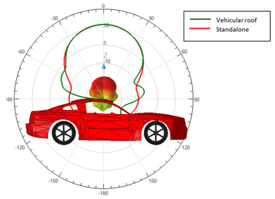
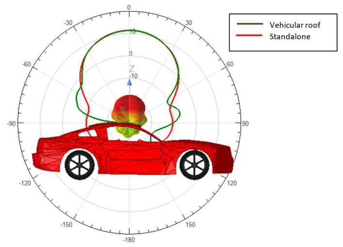
We consider a mmWave V2X-IoT network configuration operating at 28 GHz, in which the base station is modeled with an planar antenna array [33], (64 radiating elements) while each vehicular user employs a antenna array. Both the base station and user-side arrays are designed using the FADDM-based antenna synthesis approach. The base station array is first evaluated in terms of return loss, , and total realized gain, . Similarly, the vehicular antenna array is characterized by its return loss, , and realized gain, , to verify its suitability for compact on-vehicle deployment. The user antenna is mounted on the car roof, as shown in Figure 1. The roof-mounted pattern is nearly identical to the standalone array pattern, indicating that the vehicle platform has only a minor effect on the antenna radiation characteristics.
Figure 1.
Radiation patterns of the user antenna array in the standalone case and when mounted on the vehicle roof.
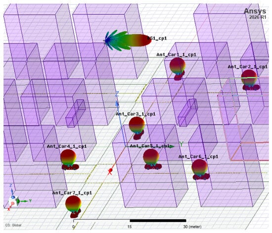
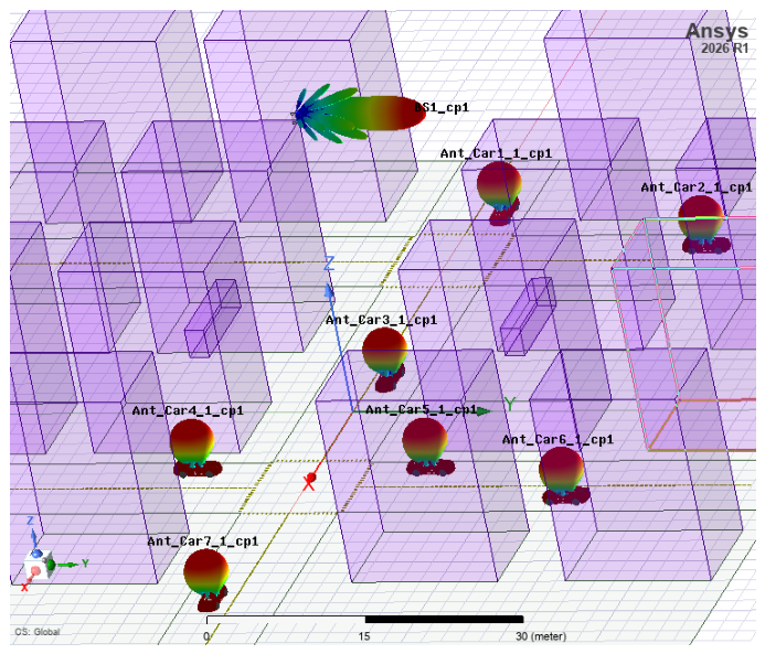
The base station is then positioned at the top of a building, above ground level, and seven vehicular users are distributed around it, as illustrated in Figure 2. To capture the effects of realistic urban propagation, the communication environment is modeled using the shooting-and-bouncing ray (SBR) solver, which accounts for reflections, scattering, and blockage caused by the city geometry.
Figure 2.
Small-city geometry showing the base station and seven surrounding vehicular users.
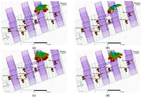
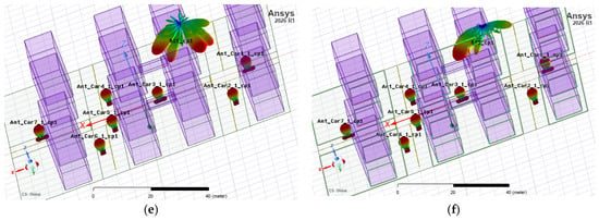
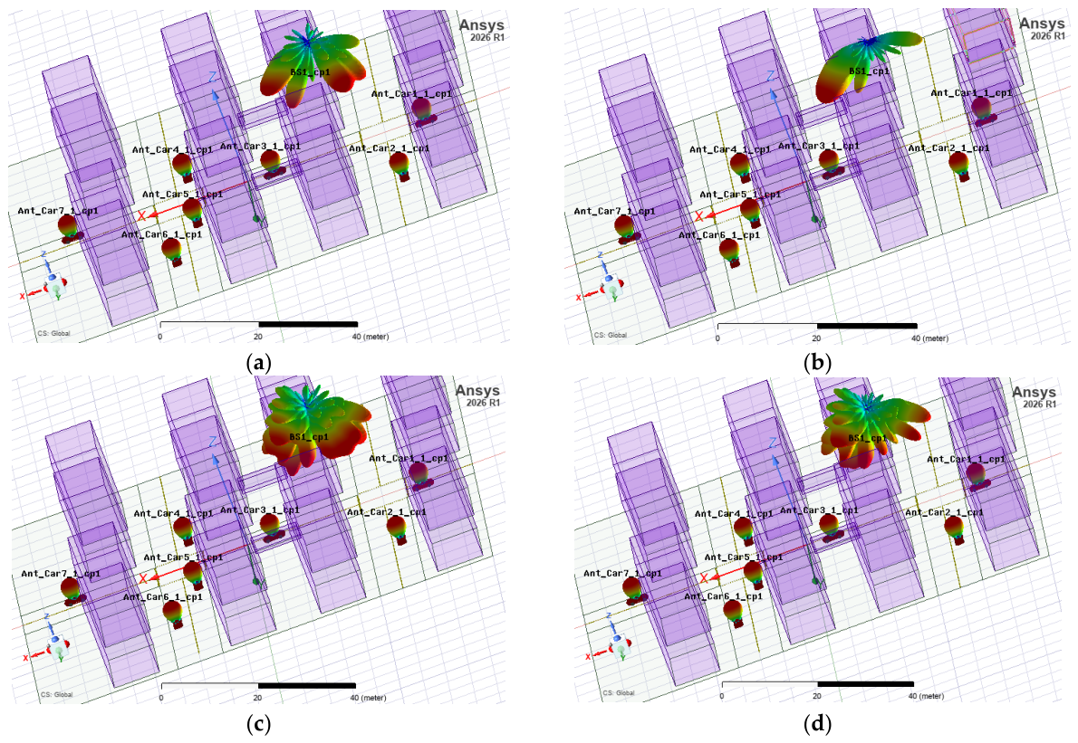
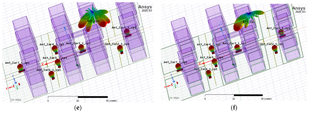
We embed the MU-MIMO V2X-IoT channels in a Python-based, Divergent-automated system-level simulation environment to evaluate dual-sided beamforming performance. In this framework, we implement three linear precoding and combining strategies: MRT with MRC, ZF, and LMMSE. Each scheme is evaluated both with and without fairness optimization, using the α-fair utility formulation, with proportional fairness . The beamforming and combining vectors calculated using Equations (7)–(12) are mapped to the antenna-port excitation magnitudes and phases in Ansys Electronics Desktop to obtain the radiation patterns shown in Figure 3. These patterns link the mathematical formulation to the electromagnetic response. The resulting beam alignment in Figure 3 shows the interaction between the base station beams and the user-side receive beams under different optimization settings at SNR 20 dB.
Figure 3.
Beam alignment among BS and users for various beamforming methods: (a) MRT-MRC dual-sided, (b) MRT-MRC balanced dual-sided, (c) ZF dual-sided, (d) ZF balanced dual-sided, (e) LMMSE dual-sided, and (f) LMMSE balanced dual-sided.
BS beams to the strongest departure path that contributes to seven receivers, as follows. Figure 3a,b show MRT-MRC beam alignment without and with -fairness, respectively. Fairness reshapes power allocation and improves user balance. This implies that the received power of each user receives equal power, as shown in the capacity in Figure 4. Figure 3c,d present the corresponding ZF results, where interference suppression is more pronounced, and the impact of fairness is clearly seen in the redistribution of beam power among users. Figure 3e,f show the LMMSE-based beamforming and combining results without and with fairness, respectively. Receiver-side processing improves robustness to interference and noise, and fairness further balances service across the seven users.
Figure 4.
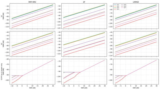
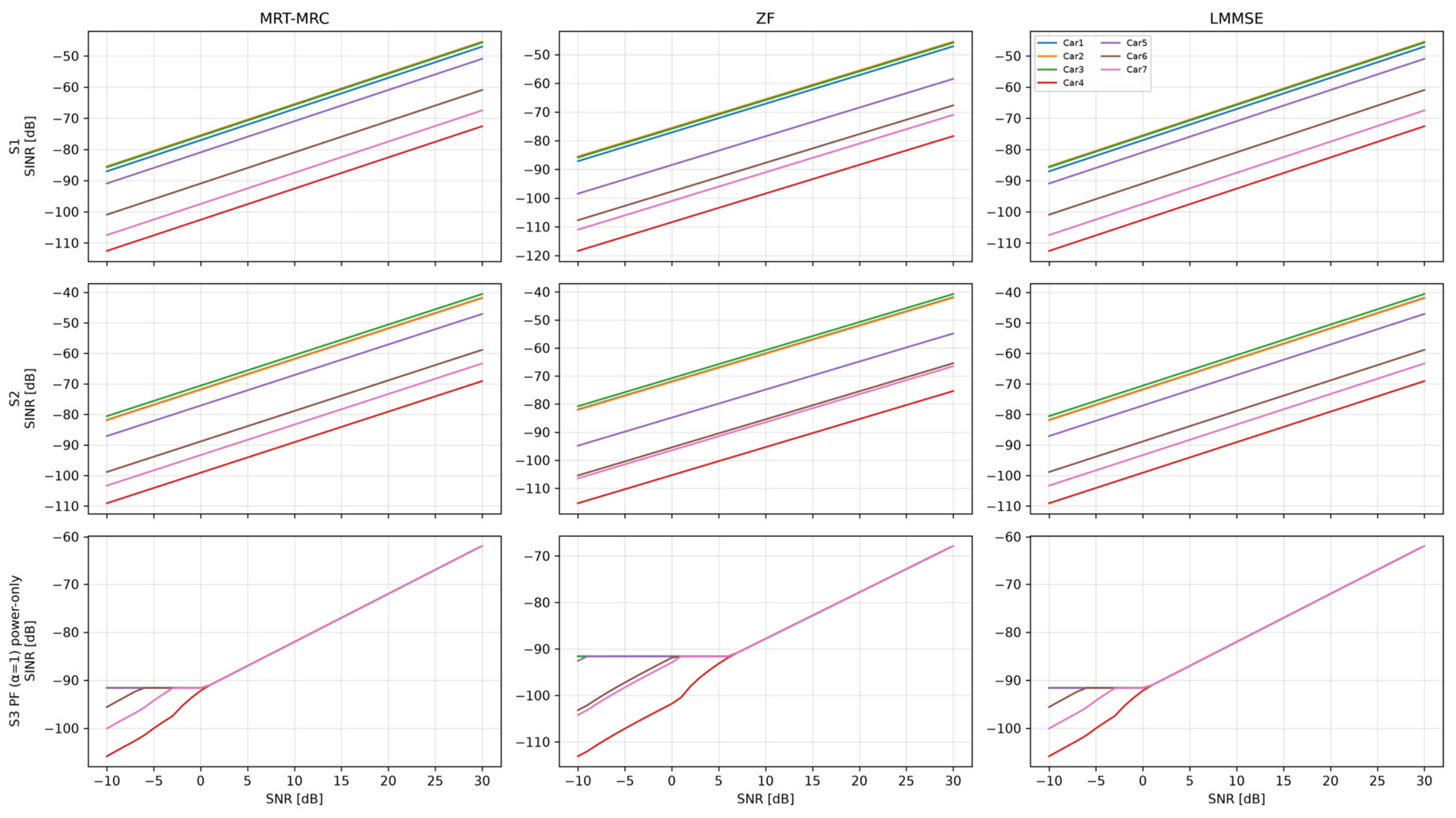
SINR for each receive user, for all methods and scenarios across SNR.
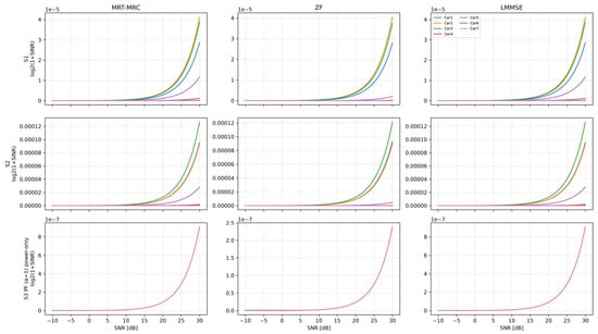
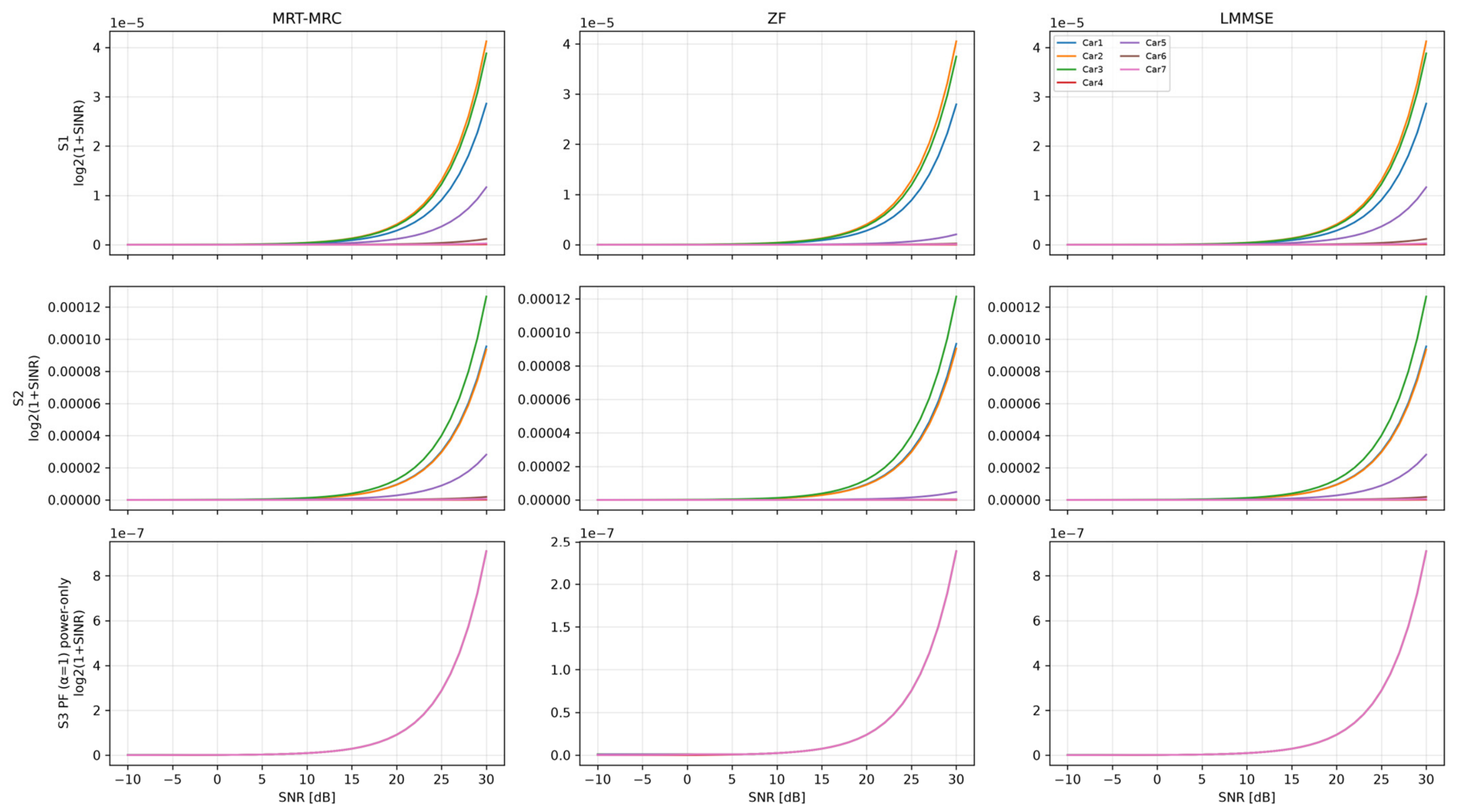
Overall, these results demonstrate how realistic antenna design, platform-dependent electromagnetic effects, urban channel modeling, and dual-side beamforming jointly determine the communication performance of mmWave V2X networks. Moreover, Figure 4 and Figure 5 show the dual-side beamforming performance of the mmWave V2X network in terms of SINR and Capacity across the SNR range , respectively, for three scenarios of all three methods: MRT-MRC, ZF, and LMMSE. The first scenario applies precoding only at the BS. The second scenario implements dual-side beamforming, with precoding at the BS and combining at the receivers. The third scenario applies α-fairness to the second scenario.
Figure 5.
Capacity for each receive user for all methods and scenarios across SNR.
The seven users are placed at different locations to represent a range of urban channel conditions, including near and distant links and line-of-sight (LOS) and non-line-of-sight (NLOS) propagation. The SINR and capacity differences in Figure 4 and Figure 5 reflect the combined effects of distance and blockage, and the resulting effective channel conditions. This placement enables the methods with these three scenarios to be compared across heterogeneous links. In contrast, the identical user capacities in the third row demonstrate the capacity-balancing outcome of the fairness operation. Figure 4 and Figure 5 are grouped as follows. Rows show the methods, and columns show the scenarios. The first row presents S1, implementing only MRT, ZF, and LMMSE precoding. The second row presents S2, implementing MRT-MRC, ZF, and LMMSE dual-sided beamforming. The last row presents S3, implementing balanced dual-sided beamforming for the three methods.
As described in (5), SINR is directly proportional to the estimated received power of the desired user, while inversely proportional to the estimated received power of the undesired users. Dual-sided beamforming capacities for each user in the second row of Figure 5 are higher than in the first row because the receiver applies combining. At 25 dB, the corresponding values for user 3 are approximately 4 × 10⁻⁵ and 1 × 10−5 bit/s/Hz of S2 and S1, respectively. This result quantifies the benefit of including vehicle-side receive combining in the evaluated urban deployment. Within the proposed framework, the comparison connects the modeled vehicular-array response to end-to-end communication performance, rather than assessing BS precoding alone.
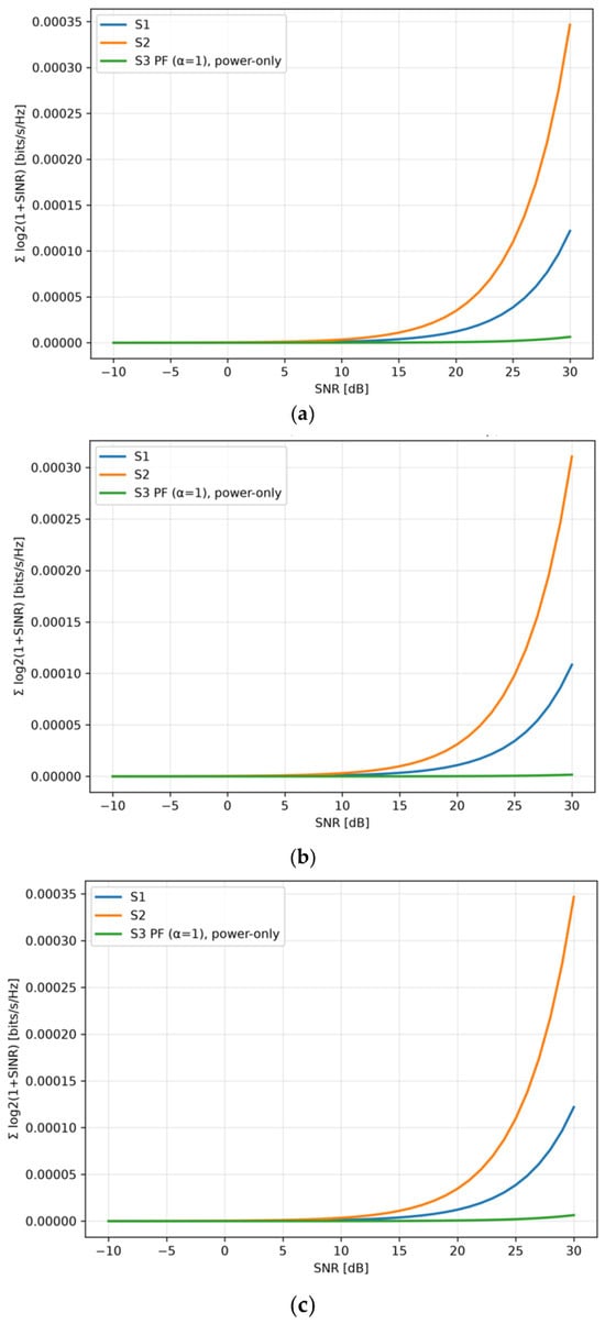
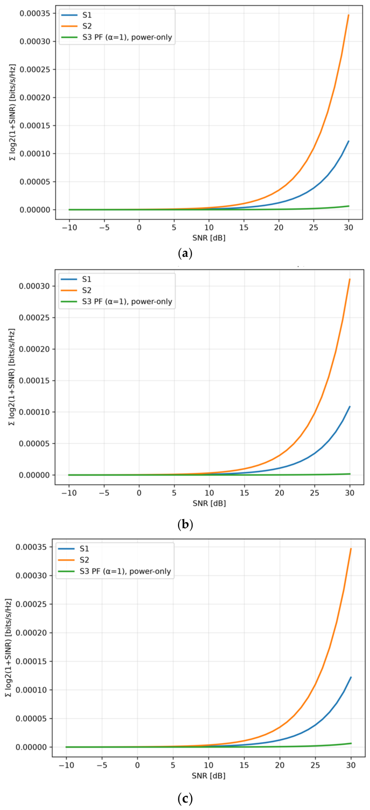
In the third row of Figure 4 and Figure 5, capacities for all seven receivers are identical for each method. This equalization shows that the fairness operation balances achieved capacities across users rather than letting favorable links dominate the allocation. Within each method, the resulting common capacity indicates that the allocation compensates for differences among the users’ effective channel conditions. Thus, these results demonstrate the fairness outcome at the user-performance level, beyond the power redistribution illustrated by the radiation patterns. The close agreement of the third and first columns indicates that LMMSE provides only a limited additional aggregate-rate benefit over MRT–MRC under the evaluated channel conditions. Figure 6 presents the total spectral efficiency across SNR, which is the summation of the achievable data rate per Hz, as described in (6).
Figure 6.
Spectral efficiency across SNR for all scenarios of (a) MRT-MRC, (b) ZF, and (c) LMMSE schemes.
Notably, in Figure 6, dual-sided beamforming achieves the best spectral efficiency across all methods, while fairness spectral efficiency is the worst because it considers only power fairness. This tradeoff is meaningful for V2X-IoT applications. Although the fairness-aware configuration reduces total spectral efficiency, it improves the availability of communication resources for distant and weak vehicular IoT nodes, which may be preferable when network-wide reliability and cooperative awareness are prioritized over peak aggregate throughput.
5. Conclusions
This article presents and simulates dual-side beamforming for a multi-user 28 GHz mmWave massive MIMO V2X-IoT system using realistic antenna and urban propagation models. The performance of MRT–MRC, ZF, and LMMSE beamforming is evaluated in terms of SINR, achievable capacity, and total spectral efficiency over an SNR range dB. In addition, the corresponding base-station radiation patterns are examined to assess beam alignment and power distribution among the vehicular users.
LMMSE and MRT–MRC beam patterns exhibit similar radiation behavior, whereas the ZF beam pattern directs more power to the users by suppressing inter-user interference through spatial nulling. The fairness-aware BS beam is stronger toward the farthest or weakest user than toward the nearest user. The results show that dual-sided beamforming achieves the highest SINR, capacity, and total spectral efficiency among the configurations considered. This improvement stems from joint processing of transmit precoding at the BS and receive combining at the vehicles. Therefore, dual-sided beamforming enhances the roadside IoT access point’s and vehicle-mounted arrays’ ability to maintain high-quality directional links. However, the fairness-aware configurations yield lower spectral efficiency across all three beamforming methods. This reduction is expected, because the fairness strategy prioritizes balanced user performance over maximizing spectral efficiency. As a result, some transmit power shifts from strong users to weaker users, reducing overall spectral efficiency while improving the accessibility of weak and distant vehicular IoT nodes. This supports a more balanced communication service relevant to cooperative, safety-critical, and sensing-intensive V2X-IoT applications. The performance results highlight the fundamental tradeoff between spectral efficiency and accessibility. Future work may investigate joint optimization of beam directions and power allocation, adaptive α selection, vehicle mobility, and fairness-aware WMMSE beamforming.
Author Contributions
Conceptualization, W.Q.M. and H.A.-R.; methodology, W.Q.M., H.A.-R., G.N., B.T. and V.S.; software, W.Q.M., H.A.-R., G.N., B.T. and V.S.; validation, W.Q.M., H.A.-R. and B.T.; formal analysis, W.Q.M., H.A.-R., G.N., B.T. and V.S.; investigation, W.Q.M. and H.A.-R.; resources, W.Q.M., H.A.-R., G.N., B.T. and V.S.; data curation, W.Q.M. and B.T.; writing—original draft preparation, W.Q.M.; writing—review and editing, W.Q.M., H.A.-R., G.N. and B.T.; visualization, W.Q.M., H.A.-R., G.N., B.T. and V.S.; supervision, W.Q.M. and H.A.-R.; project administration, W.Q.M. and H.A.-R.; All authors have read and agreed to the published version of the manuscript.
Funding
This research received no external funding.
Data Availability Statement
The original contributions presented in this study are included in the article. Further inquiries can be directed to the corresponding author.
Conflicts of Interest
Authors Gustavo Navarro, Bamelak Tadele, and Volodymyr Shyianov were employed by the company Divergent Physics, Inc., San Leandro, USA. The remaining authors declare no conflicts of interest.
References
- Tan, J.; Luan, T.H.; Guan, W.; Wang, Y.; Peng, H.; Zhang, Y.; Zhao, D.; Lu, N. Beam Alignment in mmWave V2X Communications: A Survey. IEEE Commun. Surv. Tutor. 2024, 26, 1676–1709. [Google Scholar] [CrossRef] [Scilit]
- Iwaki, R.; Nakazato, J.; Maruta, K.; Tsukada, M.; Ochiai, H.; Esaki, H. Enhancing V2X Communication: Machine Learning Assisted Dynamic mmWave Beam Search. In Proceedings of the International Conference on Ubiquitous and Future Networks, ICUFN, Budapest, Hungary, 2–5 July 2024; IEEE: New York, NY, USA, 2024; pp. 404–409. [Google Scholar] [CrossRef] [Scilit]
- Rajaganapathi, R.; Senthilkumar, S.; Alabdulkreem, E.; Alruwais, N. Improving spectral efficiency in distributed massive MIMO in multi-user downlink millimeter wave. Sci. Rep. 2026, 16, 6325. [Google Scholar] [CrossRef] [Scilit]
- Belgacem, A.; Bradai, A. Enhancing beamforming performance in 6G-V2X base stations using meta-deep reinforcement Q-learning. Internet Things 2026, 35, 6325. [Google Scholar] [CrossRef] [Scilit]
- Palhares, V.; Studer, C. An Optimization-Based User Scheduling Framework for mmWave Massive MU-MIMO Systems. In Proceedings of the IEEE Workshop on Signal Processing Advances in Wireless Communications, Oulu, Finland, 4–6 July 2022; IEEE: New York, NY, USA, 2022. [Google Scholar] [CrossRef] [Scilit]
- Hosseini, S.M.; Shahsavari, S.; Rosenberg, C. Multi-User Scheduling in Hybrid Millimeter Wave Massive MIMO Systems. In Proceedings of the 2022 IEEE Wireless Communications and Networking Conference (WCNC), Austin, TX, USA, 10–13 April 2022; IEEE: New York, NY, USA, 2022; pp. 1617–1622. [Google Scholar] [CrossRef] [Scilit]
- Ghamnia, I.; Slock, D.; Yuan-Wu, Y. Multi-User MIMO Max-Min User Rate via Weighted MSE Balancing. In Proceedings of the 2019 16th International Symposium on Wireless Communication Systems (ISWCS), Oulu, Finland, 27–30 August 2019; pp. 298–303. [Google Scholar] [CrossRef] [Scilit]
- Jayakumar, R.; Arul, A. A Survey on Beamspace Millimeter-wave Massive MIMO Systems: An Overview of Open Issues, Challenges, and Future Research Trends. Int. J. Sens. Wirel. Commun. Control 2024, 14, 1–20. [Google Scholar] [CrossRef] [Scilit]
- Xu, W.; Gao, F.; Tao, X.; Zhang, J.; Alkhateeb, A. Computer Vision Aided mmWave Beam Alignment in V2X Communications. IEEE Trans. Wirel. Commun. 2023, 22, 2699–2714. [Google Scholar] [CrossRef] [Scilit]
- Xie, B.; Chen, S.; Zhou, S.; Niu, Z.; Galkin, B.; Dusparic, I. Learning-Assisted User Scheduling and Beamforming for mmWave Vehicular Networks. IEEE Trans. Veh. Technol. 2024, 73, 11262–11275. [Google Scholar] [CrossRef] [Scilit]
- He, C.; Zhao, L.; Wan, Y.; Lu, H.; Shimizu, T. Sub-6 GHz V2X-assisted MmWave optimal scheduling for vehicular networks. Veh. Commun. 2023, 41, 100610. [Google Scholar] [CrossRef] [Scilit]
- Torkzaban, N.; Khojastepour, M.A.; Farajzadeh-Tehrani, M.; Baras, J.S. Ris-Aided Mmwave Beam-Forming For Two-Way Communications Of Multiple Pairs. ITU J. Future Evol. Technol. 2023, 4, 87–101. [Google Scholar] [CrossRef] [Scilit]
- Shi, Q.; Razaviyayn, M.; Hong, M.; Luo, Z.Q. SINR Constrained Beamforming for a MIMO Multi-User Downlink System: Algorithms and Convergence Analysis. IEEE Trans. Signal Process. 2016, 64, 2920–2933. [Google Scholar] [CrossRef] [Scilit]
- Dubey, M.; Wang, P.C.; Dubey, V. Hybrid Beamforming for mmWave V2X Using Simulated Annealing with Local Search. In Proceedings of the 2025 IEEE International Conference on Emerging Trends in Engineering and Computing, ETECOM 2025, Riffa, Bahrain, 29–30 October 2025; IEEE: New York, NY, USA, 2025. [Google Scholar] [CrossRef] [Scilit]
- Sun, X.; Qi, C.; Li, G.Y. Beam Training and Allocation for Multiuser Millimeter Wave Massive MIMO Systems. IEEE Trans. Wirel. Commun. 2019, 18, 1041–1053. [Google Scholar] [CrossRef] [Scilit]
- Tang, H.; Ding, F.; Zhao, H.; Wu, J.; Hui, X. A Collaborative Optimization Scheme for Beamforming and Power Control in MIMO-Based Internet of Vehicles. Mathematics 2025, 13, 2927. [Google Scholar] [CrossRef] [Scilit]
- Zeng, C.; Wang, J.-B.; Xiao, M.; Pan, Y.; Chen, Y.; Yu, H. Generalized Optimization Method of Placement and Beamforming Design for Multiuser MIMO UAV Communications. IEEE Wirel. Commun. Lett. 2024, 13, 402–406. [Google Scholar] [CrossRef] [Scilit]
- Tse, D.; Viswanath, P. Fundamentals of Wireless Communication; Cambridge University Press: Cambridge, UK, 2005. [Google Scholar] [CrossRef] [Scilit]
- Tarighat, A.; Sadek, M.; Sayed, A.H. A multi user beamforming scheme for downlink MIMO channels based on maximizing signal-to-leakage ratios. In Proceedings of the Proceedings. (ICASSP ‘05). IEEE International Conference on Acoustics, Speech, and Signal Processing, 2005, Philadelphia, PA, USA, 18–23 March 2005; Volume 3, pp. iii/1129–iii/1132. [Google Scholar] [CrossRef] [Scilit]
- Sur, S.N.; Kandar, D.; Silva, A.; Nguyen, N.D.; Nandi, S.; Do, D.T. Hybrid Precoding Algorithm for Millimeter-Wave Massive MIMO-NOMA Systems. Electronics 2022, 11, 2198. [Google Scholar] [CrossRef] [Scilit]
- Wen, L.; Qian, H.; Kang, K.; Luo, X.; Li, M. Low complexity hybrid beamforming for downlink multi-user MIMO OFDM systems. Digit. Signal Process. 2024, 149, 104488. [Google Scholar] [CrossRef] [Scilit]
- Hamid, S.; Chopra, S.R.; Gupta, A.; Tanwar, S.; Florea, B.C.; Taralunga, D.D.; Alfarraj, O.; Shehata, A.M. Hybrid Beamforming in Massive MIMO for Next-Generation Communication Technology. Sensors 2023, 23, 7294. [Google Scholar] [CrossRef] [Scilit]
- Björnson, E.; Kountouris, M.; Bengtsson, M.; Ottersten, B. Receive Combining vs. Multi-Stream Multiplexing in Downlink Systems with Multi-Antenna Users. IEEE Trans. Signal Process. 2013, 61, 3431–3446. [Google Scholar] [CrossRef] [Scilit]
- Yang, Y.-H.; Lin, S.-C.; Su, H.-J. Multiuser MIMO Downlink Beamforming Design Based on Group Maximum SINR Filtering. IEEE Trans. Signal Process. 2011, 59, 1746–1758. [Google Scholar] [CrossRef] [Scilit]
- Jafar, S.A.; Vishwanath, S.; Goldsmith, A. Channel capacity and beamforming for multiple transmit and receive antennas with covariance feedback. In Proceedings of the ICC 2001. IEEE International Conference on Communications. Conference Record (Cat. No.01CH37240), Helsinki, Finland, 11–14 June 2001; Volume 7, pp. 2266–2270. [Google Scholar] [CrossRef] [Scilit]
- Hamidian, K.; Mohamed, W.Q. Performance Enhancement of MIMO—MGSTC Using a New Detection and Decoding Technique; Advances in Intelligent Systems and Computing; Springer International Publishing: Singapore, 2018; pp. 12–25. [Google Scholar] [CrossRef] [Scilit]
- Younas, T.; Shen, J.; Mekonnen, M.; Farid, G.; Gao, M.; Younas, O.; Liaqat, M.; Munir, H.M. Achieving Bandwidth Efficiency in 3d Massive MIMO Through 2d Precoding Schemes. SSRN Electron. J. 2022. [Google Scholar] [CrossRef] [Scilit]
- Jacobsson, S.; Durisi, G.; Coldrey, M.; Goldstein, T.; Studer, C. Quantized precoding for massive MU-MIMO. IEEE Trans. Commun. 2017, 65, 4670–4684. [Google Scholar] [CrossRef] [Scilit]
- Kang, J.; Choi, W. Coordinated regularized zero-forcing beamforming with channel statistics based adaptive feedback for cooperative massive MIMO networks. ICT Express 2021, 7, 10–14. [Google Scholar] [CrossRef] [Scilit]
- Kebede, T.; Wondie, Y.; Steinbrunn, J.; Kassa, H.B.; Kornegay, K.T. Precoding and Beamforming Techniques in mmWave-Massive MIMO: Performance Assessment. IEEE Access 2022, 10, 16365–16387. [Google Scholar] [CrossRef] [Scilit]
- Li, H.; Yang, S.; Wen, Z.; Cao, J.; Lu, G.; Wang, Z.; Wang, H. α-Fairness-based joint power allocation and power splitting for massive MIMO systems with SWIPT. Digit. Signal Process. Rev. J. 2022, 120, 103219. [Google Scholar] [CrossRef] [Scilit]
- Kim, K.; Myung, J.; Ko, Y.J.; Lee, W.Y. Beamforming and Power Optimization for User Fairness in Cell-Free MIMO Systems. IEEE Access 2023, 11, 51032–51046. [Google Scholar] [CrossRef] [Scilit]
- Mohamed, W.Q.; Al-Rizzo, H.; Rashid, H. Deep Learning-Based Rigorous Electromagnetic Framework for Direction of Arrival Estimation in Millimeter-Wave Communication Systems Based on Embedded Radiation Patterns. Electronics 2026, 15, 2934. [Google Scholar] [CrossRef] [Scilit]

Disclaimer/Publisher’s Note: The statements, opinions and data contained in all publications are solely those of the individual author(s) and contributor(s) and not of MDPI and/or the editor(s). MDPI and/or the editor(s) disclaim responsibility for any injury to people or property resulting from any ideas, methods, instructions or products referred to in the content. |
© 2026 by the authors. Licensee MDPI, Basel, Switzerland. This article is an open access article distributed under the terms and conditions of the Creative Commons Attribution (CC BY) license.