


Abstract
For 5G tunnel communications, antennas often face critical challenges arising from severe path loss and multipath fading in confined environments, as well as polarization mismatch under dynamic propagation conditions. This paper proposes a 3.5-GHz circularly polarized (CP) endfire antenna array with bidirectional right-hand CP radiation, featuring high gain, low profile, and compact configuration. The array is implemented on a single-layer F4B substrate and integrates eight pairs of electric and magnetic dipoles to synthesize orthogonal linear field components required for CP radiation. By applying the extended method of maximum power transmission efficiency, constraints on the amplitude and phase are introduced to maximize the CP gain in the endfire direction. A 16-element linear array prototype is fabricated and tested for validation. Measurement results show that the proposed array achieves a bidirectional right-hand CP endfire gain exceeding 12.2 dBic, an impedance bandwidth from 3.1 to 3.78 GHz, and a 3 dB axial ratio bandwidth of 19.5%, demonstrating its suitability for 5G tunnel communication applications.
1. Introduction
Fifth-generation (5G) mobile communication technology enables high-speed, low-latency and massive connectivity [1]. To fulfill seamless wireless coverage, a reliable communication infrastructure is essential, particularly in challenging environments like tunnels. Tunnels represent typical waveguide-like confined spaces, where radio wave propagation suffers from severe path loss and multipath fading [2]. As a vital component of the wireless communication system, antennas play a critical role in overcoming these obstacles. In tunnel environments, equipment movement can lead to polarization mismatch, while signals are affected by strong multipath reflections and path loss [3]. Circularly Polarized (CP) antennas have significant advantages in tunnel communication applications. Their polarization is not dependent on a fixed direction, which can greatly reduce the requirement for alignment of the transmitting and receiving antennas, better suppress multipath interference, and minimize polarization mismatch loss. These characteristics are valuable in dynamic tunnel environments. CP antennas have been widely used in various wireless communication systems, such as satellite communications, Global Navigation Satellite Systems (GNSS) [4], Radio Frequency Identification (RFID) [5], and 5G sub-6 GHz networks [6,7]. The antenna array proposed in this paper combines CP with endfire radiation characteristics. This design not only addresses signal quality degradation but also optimizes the energy propagation path, improving overall energy efficiency. It realizes high-gain and high-quality bidirectional signal coverage along the tunnel axis. These advantages align well with the requirements of 5G tunnel communications, providing a reliable communication link with promising application prospects.
In recent years, planar CP endfire antennas have gained significant attention owing to their advantages of low aerodynamic drag and stable signal transmission. A variety of planar CP endfire antennas have been proposed. Conventional CP endfire antennas, such as helical antennas and Yagi antennas [8,9], while demonstrating excellent performance in free space, often possess considerable profiles due to their three-dimensional structures and poor compatibility with planar circuits. These inherent limitations make it challenging to realize low-cost, compact arrays, thereby posing significant obstacles for large-scale integration on tunnel walls and severely restricting their performance and applicability in modern communication systems. According to existing research, methods for generating CP endfire radiation include: utilizing the superposition of complementary dipoles [10,11,12], employing co-directional orthogonal dipoles [13,14], introducing rotating structures [15,16], and adopting traveling-wave or periodic structures [17,18,19], among others. In [20], a CP antenna design using complementary dipoles was introduced, achieving a 3 dB axial ratio (AR) bandwidth of over 40%. However, a tapered dielectric rod was placed in front of the antenna, and its length was gradually increased to enhance gain and AR performance. In [21], a loop antenna was proposed to achieve CP endfire radiation. The loop consists of two arms, where quasi-traveling-wave currents along the strips and vias generate orthogonal polarizations. By introducing an offset microstrip line to regulate the phase difference, good CP radiation was obtained. To achieve higher gain, a dielectric rod was added, resulting in an endfire gain of 9 dBic. A similar loop-based CP design was reported in [22]. Notably, refs. [23,24] introduced a single-layer, single-fed CP endfire antenna with unidirectional radiation characteristics by introducing parasitic reflectors and directors. Most of the reported CP endfire antennas enhance endfire gain through introducing parasitic elements in antenna designs, while these CP endfire solutions predominantly remain single-element configurations with inherent limitations, including relatively large structures and constrained gain performance.
While array synthesis is a common approach to enhance gain, strong mutual coupling between antenna elements can significantly detune the input impedance of individual elements, resulting in impedance mismatch at feeding ports. Moreover, it disturbs the amplitude and phase distribution across the array, directly impairing the amplitude balance and phase difference between the two orthogonal modes required for CP operation. In [25], a 1 × 4 complementary dipole antenna array achieved an operating bandwidth of 24.6% and a peak gain of 9.3 dBic, but its feeding network occupied considerable space. Therefore, designing a planar CP endfire antenna array that offers high gain, compact configuration, and miniaturization remains a challenging task.
The bidirectional RHCP endfire antenna array proposed in this paper operates at 3.5 GHz, based on the extended method of maximum power transmission efficiency, achieving high gain and compact miniaturization. The design employs complementary electric and magnetic dipole elements to generate orthogonal linearly polarized components, with comprehensive constraints applied to both amplitude and phase of horizontal and vertical polarized components in the endfire direction to ensure maximum radiation gain. The implemented sixteen-element linear array, which is excited through a precisely engineered 1-to-16 feed network that provides the optimal excitation distribution, demonstrates exceptional AR performance and suppressed cross-polarized levels. Compared to conventional approaches that rely on passive reflectors and directors [26], the proposed bidirectional CP endfire antenna array based on the extended method of maximum power transmission efficiency not only guarantees theoretically optimal bidirectional gain but also establishes a systematic methodology demonstrating exceptional adaptability in structural optimization.
2. Method of a Bidirectional RHCP Endfire Antenna Array Design
In order to achieve CP radiation in bidirectional endfire directions, the elements are arranged in a centrosymmetric configuration. Where is defined as the azimuth angle measured from the x-axis, and represents the elevation angle measured from the z-axis. In an n-element antenna array, the magnetic dipole generates a vertically polarized component and in the far-field, while the electric dipole generates a horizontally polarized component and . Here, the subscripts “+” and “−” denote the two opposite endfire directions, and represents the unit vector along the corresponding or direction).
In order to concentrate the radiated energy of the transmitting array toward the endfire direction, the ratio of the total radiated energy in the endfire directions to the total input power of the transmitting array is taken as the performance index, which can be expressed by [27,28,29,30]:
where denotes the normalized incident wave vector for the transmitting antenna array, and Here, represents the radiated field components from the n-element transmitting array and can be written as:
in which (i = 1, 2, , n) denotes the radiated field generated by the ith element of the array when the ith element is excited by and all other elements are terminated in matched loads.
In this paper, RHCP is to be realized in bidirectional endfire directions. The CP waves can be generated when the electric field of vertically polarized radiation and that of horizontally polarized radiation are equal in amplitude, with a phase difference of . To control the polarization of the CP wave, the electric field components in bidirectional endfire directions can be expressed as:
With the above constraint being imposed, (1) may be modified as the following constrained quadratic programming problem:
By employing the Lagrange multiplier method, the optimal solution of the above problem is given by [31]:
3. Antenna Subarray Design
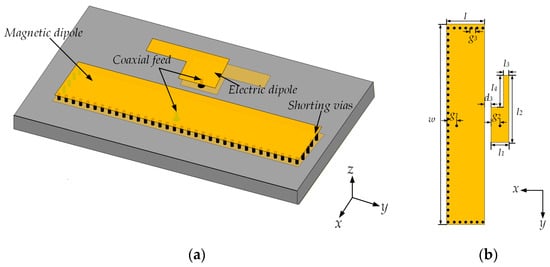
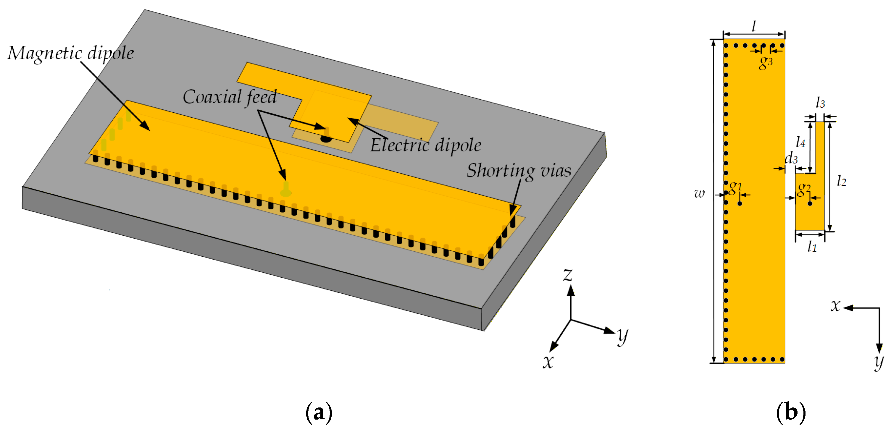
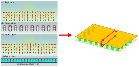
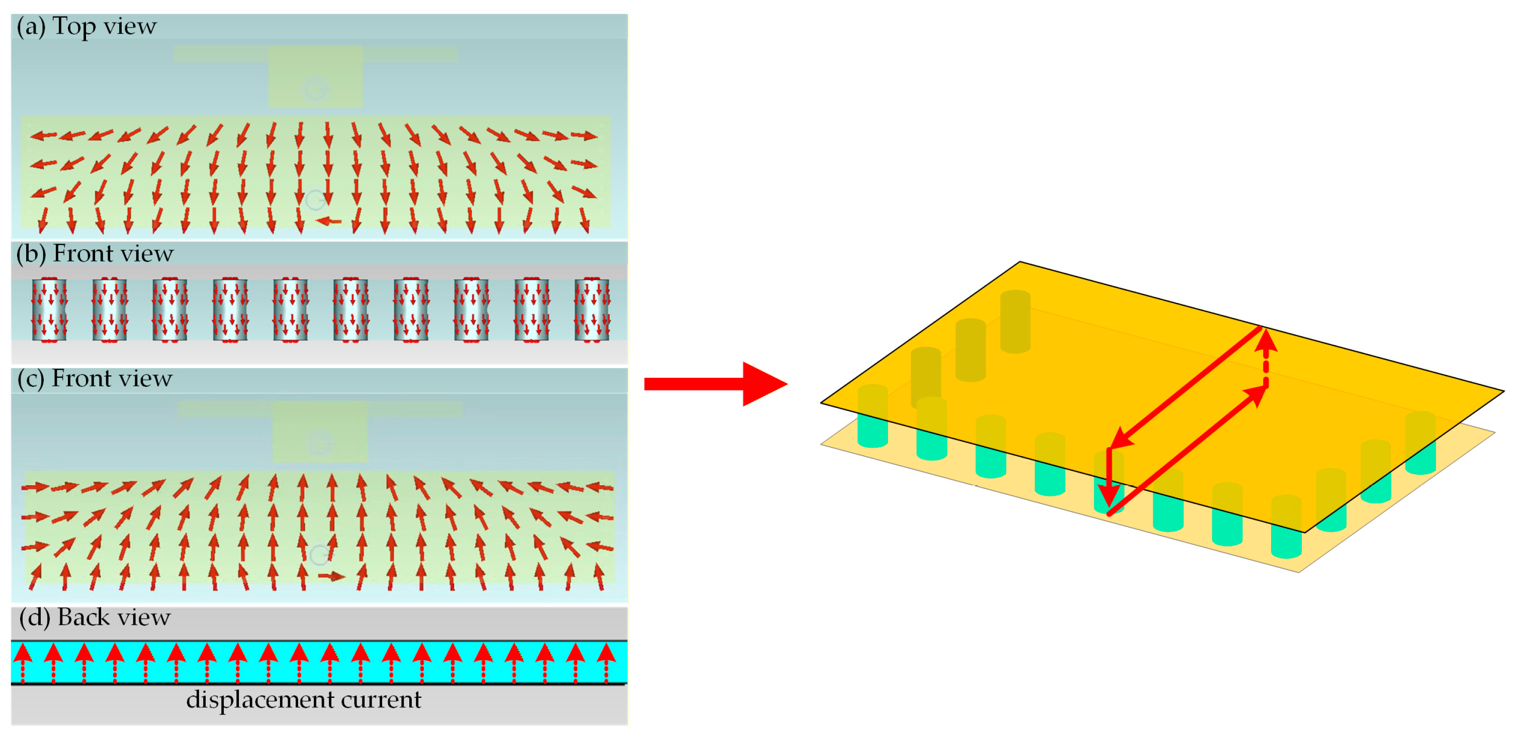
This section details the design of the subarray, which consists of a pair of electric and magnetic dipoles. As shown in Figure 1, the proposed composite element is implemented on a single-layer F4B substrate with a relative permittivity of 2.55, a loss tangent of 0.0015, and a thickness of 1.6 mm. This configuration integrates a magnetic dipole and an electric dipole in a co-planar layout, providing a stable radiation pattern. The magnetic dipole is realized using a rectangular metal patch, a coaxial feed port, and a set of shorting vias. The two rectangular patches, together with the densely spaced vias, function as an effective electric wall by enforcing a low-impedance boundary condition. As illustrated in Figure 2, the conduction currents originate from the top patch, traversing the shorting vias to reach the bottom layer. At the radiation aperture, the high-frequency time-varying electric field induces a significant displacement current, which effectively bridges the two metal layers to form a closed-loop current path. Consequently, the aperture formed between these two electric walls can be regarded as a magnetic wall, where the equivalent magnetic currents at the aperture play a dominant role in determining the magnetic flux density across it, thereby exciting a vertically polarized electric field The length and width of the magnetic dipole at the target resonant frequency of 3.5 GHz are determined through parameter adjustment and optimization.
Figure 1.
Antenna subarray design consisting of a magnetic dipole and an electric dipole. (a) 3D View. (b) Top View.
Figure 2.
Surface current distribution of the magnetic dipole.
Complementing the magnetic dipole, the electric dipole element consists of a coaxial feed, a microstrip transmission line, and a pair of dipole arms. The current on the electric dipole exhibits a standing-wave distribution, with both arms carrying currents of equal magnitude and the same direction, which is essential for generating a balanced electric dipole mode. To ensure proper excitation and impedance matching of the composite element, the length and width of the microstrip feed line are meticulously adjusted. This tuning process compensates for the reactive components introduced by mutual coupling and ensures efficient power transfer from the coaxial feed. The integration of the magnetic and electric dipoles forms a composite radiator, whose overall performance is more complex than a simple superposition of the individual components.
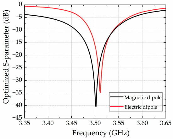
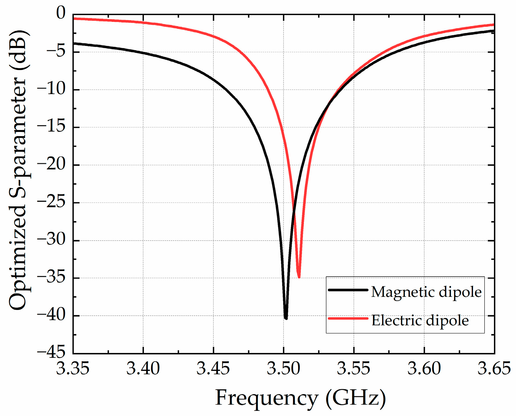
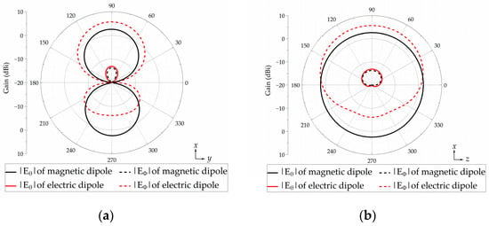
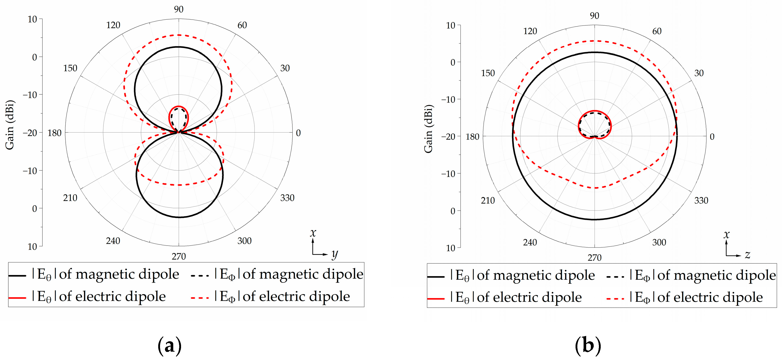
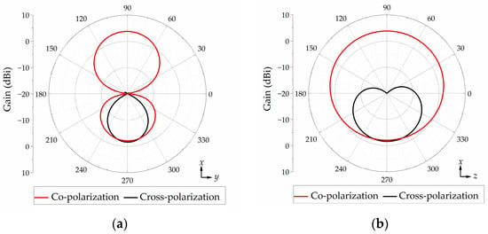
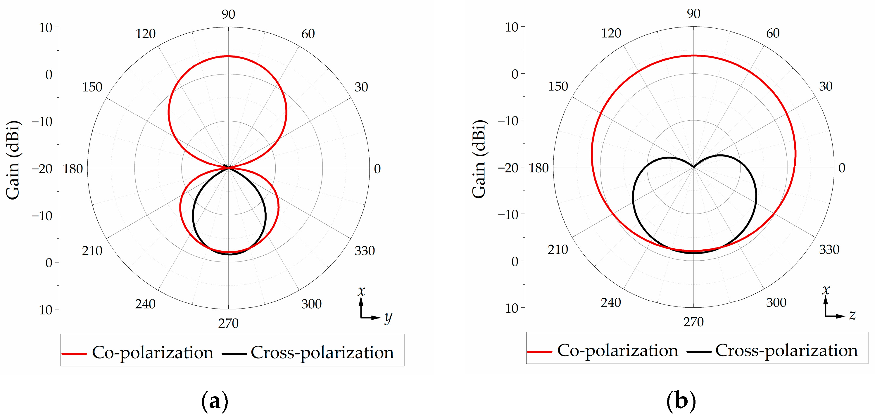
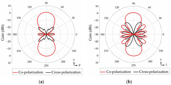
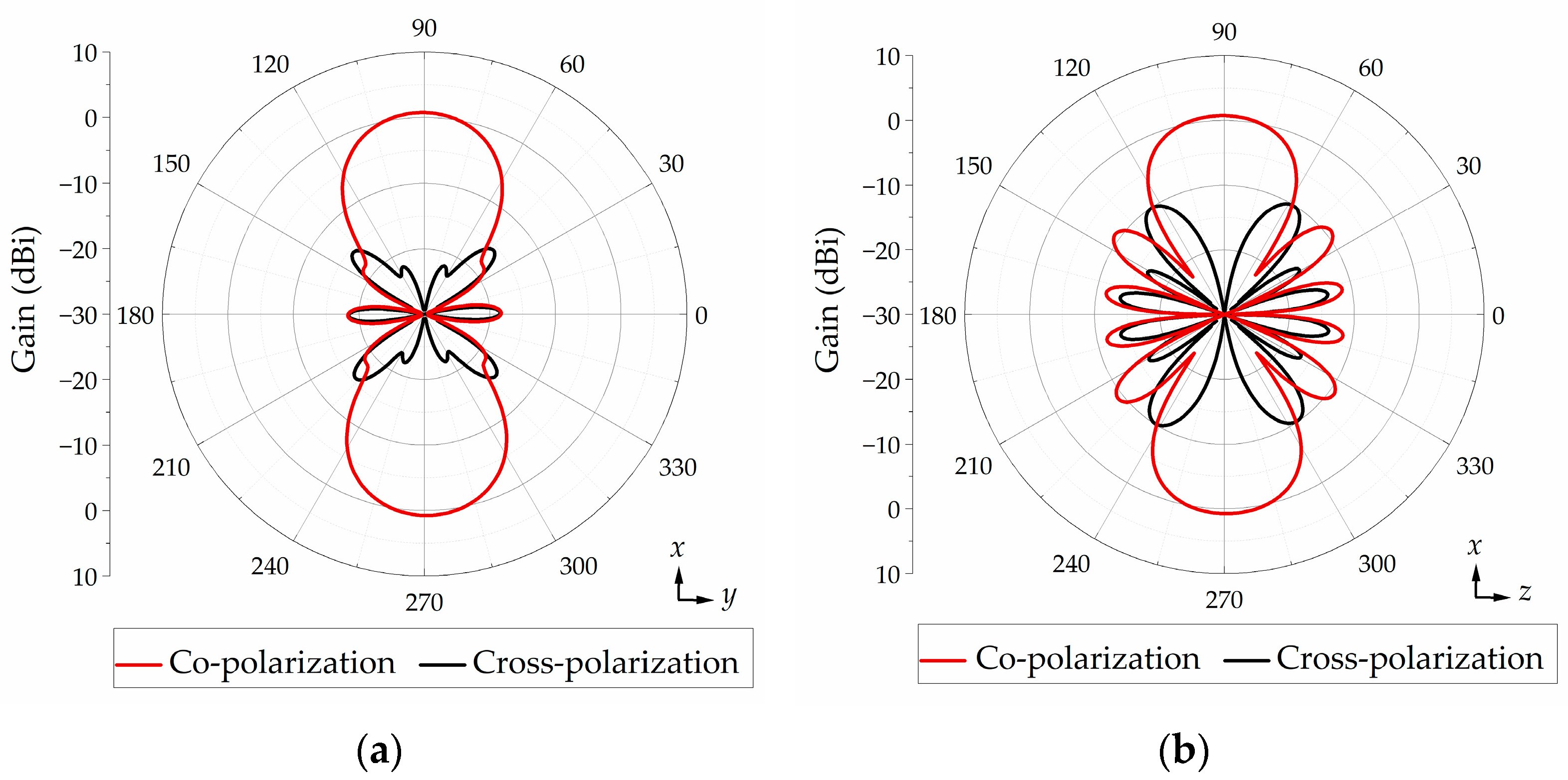
To accurately account for mutual coupling, parasitic effects, and fringe fields, the design is modeled in a high-frequency electromagnetic simulator for parametric analysis. As shown in Figure 3, the S-parameters of the optimized subarray are simulated under a full-wave simulation. At the target operating frequency of 3.5 GHz, both the magnetic dipole and the electric dipole exhibit good impedance matching with reflection coefficients lower than −30 dB. The radiation patterns of the magnetic dipole and electric dipole at the target frequency of 3.5 GHz are shown in Figure 4 to evaluate their radiation characteristics as array elements. The simulation patterns clearly demonstrate that both dipole antennas exhibit excellent endfire radiation, with their main beams aligned along the antenna plane, which is fully consistent with the design expectations. The magnetic dipole element primarily provides vertical polarized radiation, and its patterns in both the xy-plane and xz-plane show concentrated forward radiation energy with effectively suppressed back lobes, thereby validating its effectiveness as a vertical polarized radiation source. Complementarily, the electric dipole element mainly excites horizontally polarized radiation in the endfire directions. In addition, to verify the effectiveness of the CP synthesis method proposed in this work and more comprehensively evaluate the radiation characteristics of the subarray, Figure 5 further presents the radiation patterns of the composite element under simultaneous excitation of both ports at 3.5 GHz. These patterns visually illustrate the CP radiation performance of the subarray in both the xy-plane and xz-plane. The calculated cross-polarization isolation of the antenna subarray under simultaneous excitation reaches 85.3 dB, demonstrating the outstanding cross-polarization suppression capability of the proposed structure. The optimization was set to minimize the reflection coefficient at 3.5 GHz while maintaining stable radiation patterns across the target frequency band. The final dimensions, summarized in Table 1, result from this systematic simulation-driven optimization process.
Figure 3.
Simulated reflection coefficients of the optimized antenna elements.
Figure 4.
Simulated radiation patterns at 3.5 GHz. (a) xy-plane of the magnetic dipole and electric dipole and (b) xz-plane of the magnetic dipole and electric dipole.
Figure 5.
Simulated co-polarization and cross-polarization radiation patterns at 3.5 GHz. (a) xy-plane and (b) xz-plane of the subarray.
Table 1.
Optimized antenna geometric dimension parameters.
4. Antenna Array Configuration
Following the establishment of a high-performance antenna subarray design, the array configuration plays a pivotal role in achieving the targeted system performance. When extending the composite elements into an array, several topological configurations are feasible, such as side-by-side, end-to-end, axis-symmetric, and anti-symmetric layouts. These layouts fundamentally determine the inter-element electromagnetic coupling, thereby directly affecting the AR and cross-polarized levels. Parametric studies conducted via high-frequency electromagnetic simulation software demonstrate that the anti-symmetric configuration offers distinct advantages over others. This configuration effectively balances the electromagnetic fields generated by adjacent electric and magnetic dipoles, enabling the synthesis of a purer CP wave in the far-field region, consequently yielding superior polarized purity and more stable radiation patterns.
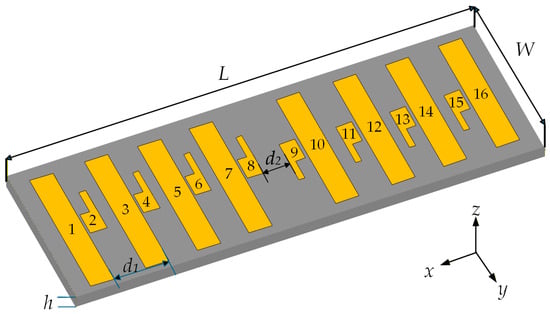
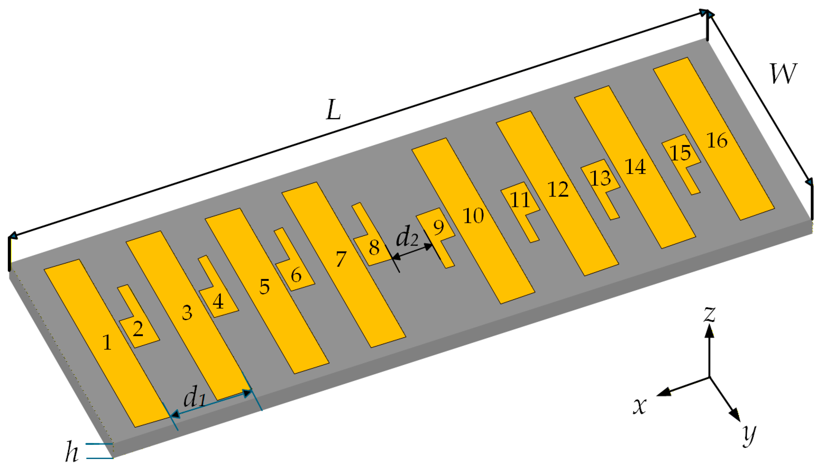
Based on this finding, we constructed a linear array comprising eight subarrays, as shown in Figure 6. Each subarray contains one electric dipole and one magnetic dipole, resulting in a total of sixteen independent radiating elements within the overall array. The array structure is meticulously designed: the four subarrays on the left and the four on the right exhibit exact anti-symmetry with respect to the x-axis at the array center. After defining the anti-symmetric element layout, the subarray spacing emerged as a critical parameter that governs both the radiative performance and physical dimensions of the array. Conventional antenna array design typically recommends an inter-subarray spacing of approximately half-wavelength (~0.5λ) to achieve high gain and suppress grating lobes. However, the design proposed in this paper represents a significant breakthrough by reducing the array subarray spacing to 0.35λ while maintaining excellent radiation performance, thereby realizing a highly compact 16-element linear array. The inter-element spacing of 0.35λ is chosen because in this design, the array with 0.35λ inter-element spacing maintains comparable gain to a 0.5λ array while significantly reducing the array size by 22.5%.
Figure 6.
Schematic diagram of the proposed 16-element array with a detailed array configuration.
Compared with traditional half-wavelength spacing arrays, this compact configuration reduces the physical structure by approximately 22.5%. Such miniaturization is crucial for deploying large-scale arrays in space-limited environments, such as a tunnel. Furthermore, the close spacing of 0.35λ effectively suppresses the excitation of higher-order modes and promotes stable propagation of the fundamental mode, thereby enhancing the link reliability in tunnel communication environments. However, the tight subarray spacing (0.35λ) inevitably introduces strong mutual coupling between elements. In conventional designs, strong mutual coupling is generally regarded as degrading radiation patterns and impedance matching. Nevertheless, this study transforms this challenge into a distinctive advantage through the adoption of the extended method of maximum power transmission efficiency for optimal endfire beamforming. As indicated by (2) in Section 2 of the manuscript, each electric-field component essentially represents the active element pattern. Therefore, the effects of mutual coupling are inherently embedded in the amplitude and phase information of the electric field . When the algorithm computes the inverse matrix to obtain the excitation vector , this process can be interpreted as compensating for the amplitude and phase at the excitation ports.
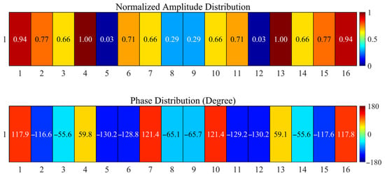
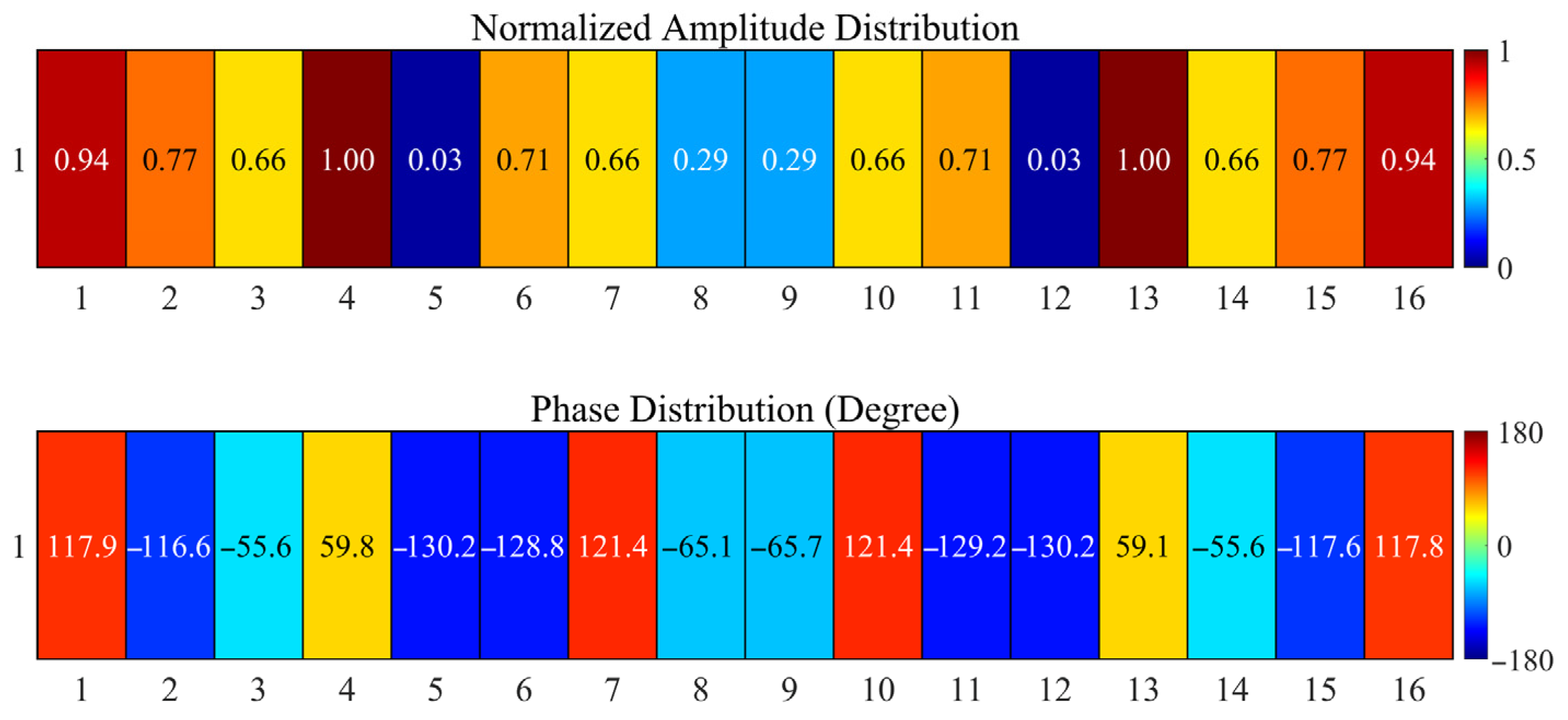
In conventional array design, mutual coupling is typically treated as an undesired interference that should be minimized or eliminated. In contrast, in the proposed approach, mutual coupling is explicitly incorporated into the matrix formulation. High-purity circular polarization is achieved not by suppressing mutual coupling, but by solving a constrained quadratic programming problem to derive an excitation vector that inherently accounts for the mutual coupling among all the array elements. The optimal excitation distribution for the sixteen antenna elements, detailed in Figure 7, reveals that the phase differences between adjacent elements no longer follow the fixed 90-degree relationship prescribed by traditional complementary antenna theory in free space. Instead, the algorithm dynamically compensates for the phase shifts caused by strong mutual coupling associated with the 0.35λ tight spacing.
Figure 7.
Optimized distribution of excitations.
5. Results and Discussion
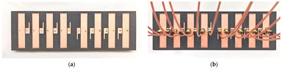
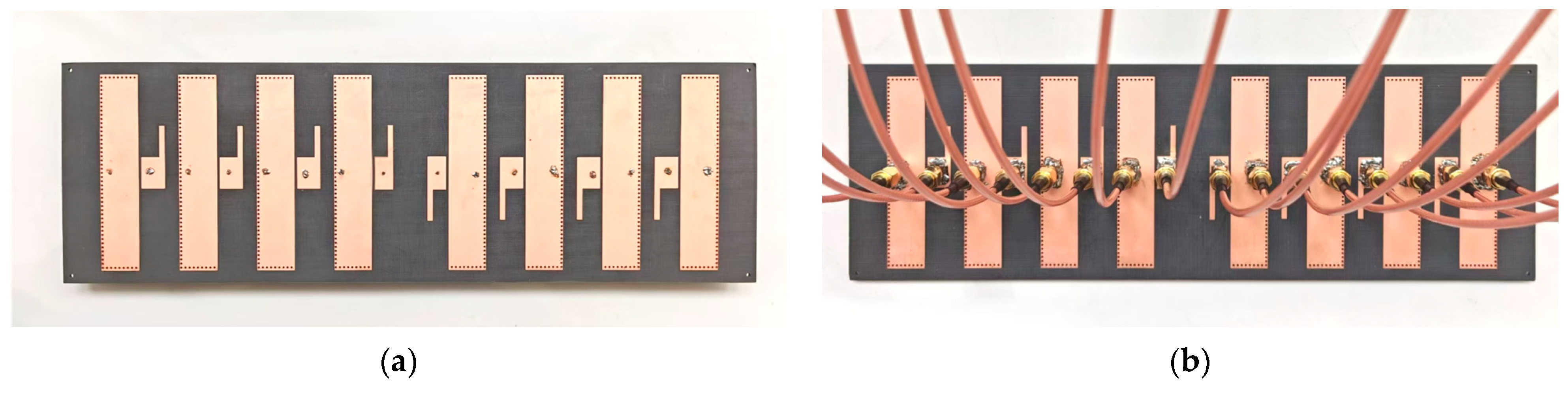
To validate the consistency between the simulated and measured results, a prototype of the proposed antenna was fabricated and measured, as is shown in Figure 8. In the experimental setup, a 1-to-2 power divider is employed to distribute the input signal into two parallel 8-channel analog phase shifting modules, which are used to excite the sixteen feeding ports of the antenna array. Each RF channel integrates a 6-bit digital attenuator and a 6-bit digital phase shifter, offering a maximum attenuation range of 31.5 dB with an amplitude resolution of 0.5 dB, and a phase resolution of 5.625°, respectively. Amplitude and phase control commands are delivered via a serial peripheral interface, allowing independent and fine-grained programming of the excitation parameters for each channel. The optimal excitation distribution derived from the proposed method is first quantized to comply with the 6-bit hardware resolution constraints and subsequently uploaded to the system through digital control. This implementation strategy ensures an accurate realization of the optimal beamforming excitation distribution in the physical RF hardware. The RF feed network is interconnected with the array via phase-stable coaxial cables to synthesize the optimized excitation distribution shown in Figure 7. Prior to the measurements, the amplitude and phase responses of the entire feeding network, comprising the power divider, phase shifters, and cables, are calibrated using a Vector Network Analyzer (VNA) manufactured by Rohde & Schwarz, located in Munich, Germany. This calibration is performed to minimize implementation discrepancies and ensure the realization of the desired bidirectional endfire radiation.
Figure 8.
Photo of the proposed antenna with (a) top view and (b) bottom view.
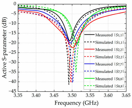
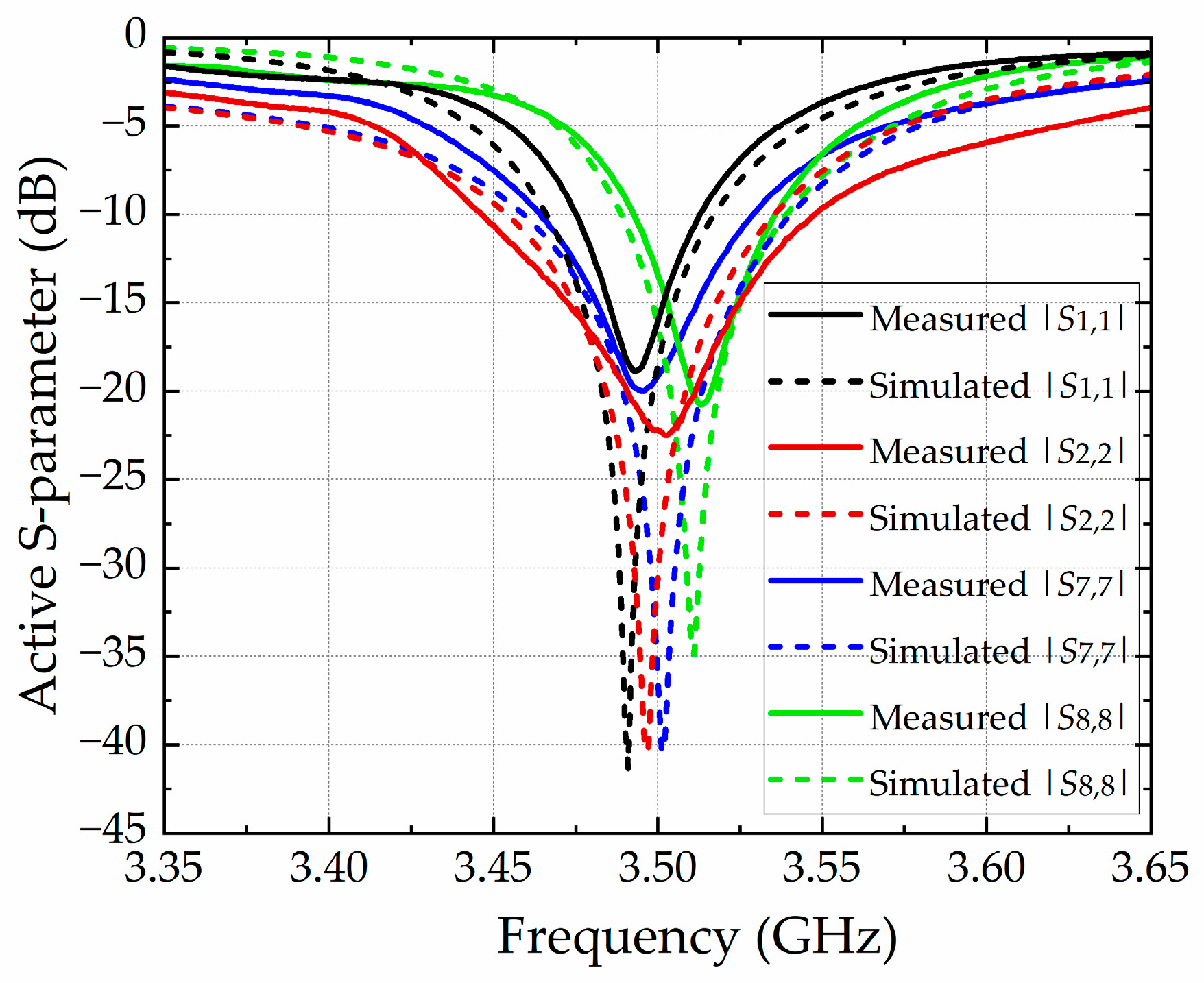
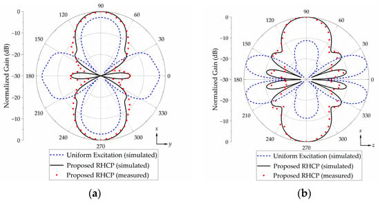
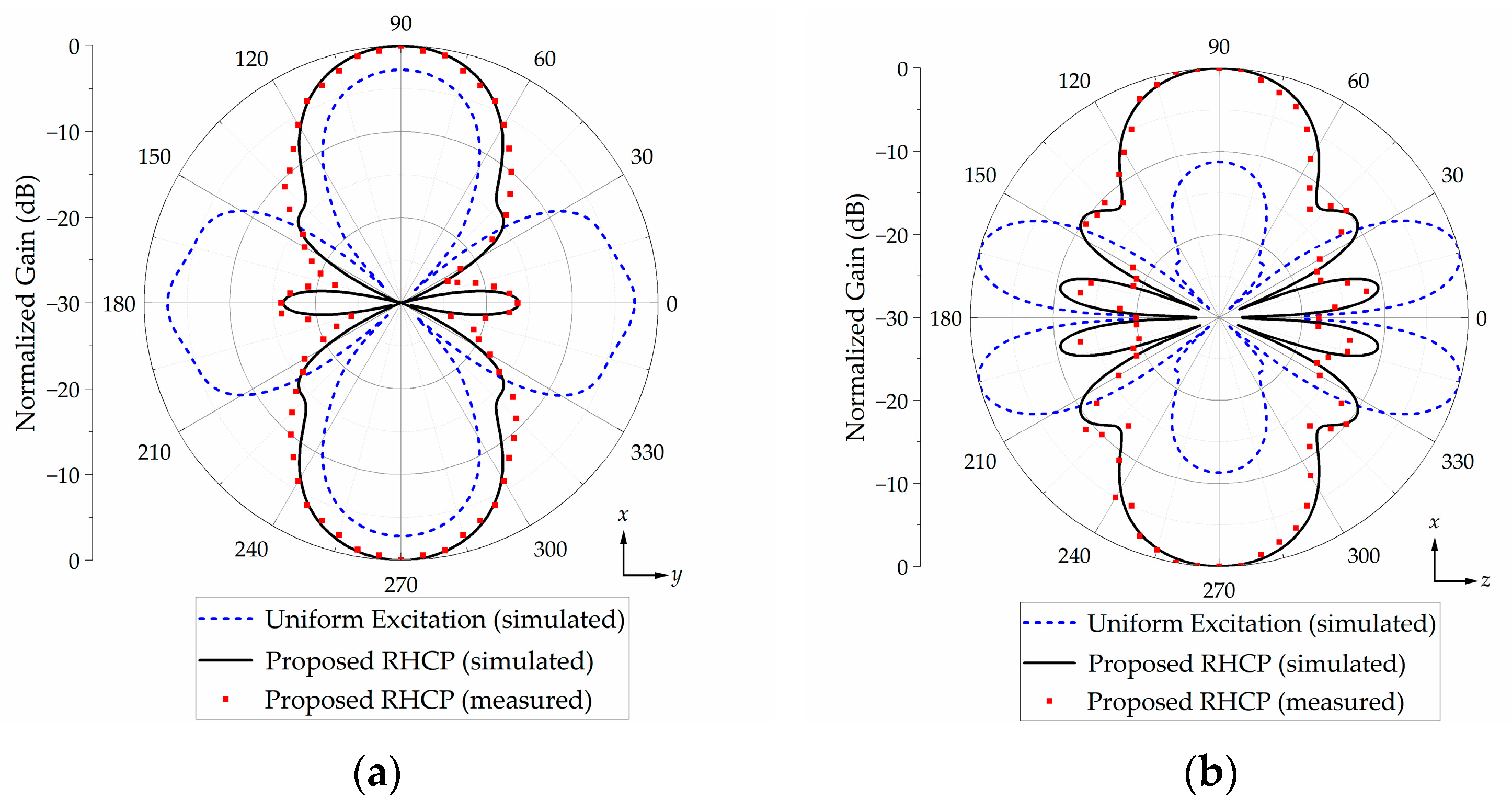
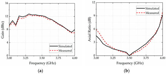
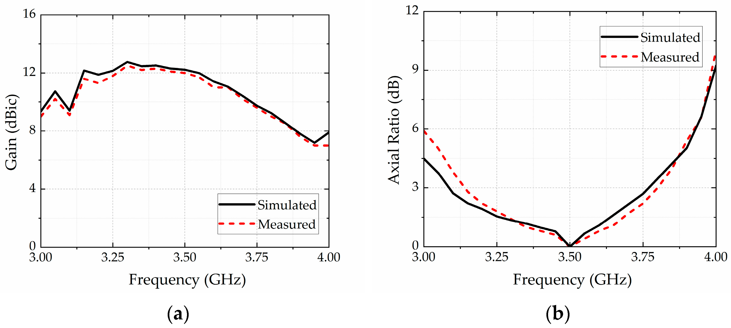
As illustrated in Figure 9, the simulated and measured reflection coefficients of the magnetic and electric dipoles at the edge and the center of the antenna array are presented. The measurement results show good agreement with the simulations. The shallower resonance depth observed in the measured curves, compared to the simulated ones, stems from inherent discrepancies between the optimized excitations and the actual implementations in the RF circuitry. It is noteworthy that, due to strong mutual coupling, the measured performance of the magnetic and electric dipoles at the array center exhibits slightly larger deviation from the ideal simulations than that of the edge elements. Figure 10 presents the bidirectional RHCP radiation patterns in both the xy-plane and xz-planes at 3.5 GHz. The half-power beamwidths are measured to be 43° in the xy-plane and 45° in the xz-plane, while the corresponding simulated 3 dB AR beamwidths are 66.6° and 35.6°. For comparison, the simulated pattern under uniform excitation (equal amplitude and phase) is plotted as a blue dashed line. Notably, while the uniform excitation directs the main beams primarily along the y-axis and z-axis (0° and 180°), the proposed excitation successfully synthesizes the main beams along the ±x-axis (90° and 270°). Furthermore, as illustrated in Figure 11, excellent co-to-cross-polarization isolation is observed with the proposed design, particularly in the endfire directions. The simulated co-to-cross-polarization isolation in the endfire direction is 99.1 dB. Figure 12 presents the simulated and measured gain and AR of the proposed antenna operating in the bidirectional RHCP state across the frequency band of 3.00 to 4.00 GHz. The measured results exhibit a high degree of consistency with the simulated data, achieving a peak of approximately 12.3 dBic around 3.35 GHz. The gain profile remains relatively flat across the center frequency band (3.25 to 3.6 GHz), maintaining levels above 11 dBic. The AR curves indicate excellent CP purity. The measured AR reaches its minimum (near 0 dB) at the center frequency of 3.50 GHz, perfectly matching the simulation. The effective 3 dB AR bandwidth broadly extends from about 3.15 to 3.75 GHz, ensuring robust CP performance for the intended application.
Figure 9.
Simulated and measured reflection coefficients of the electric dipole and the magnetic dipole.
Figure 10.
Simulated and measured radiation patterns of the array at 3.5 GHz on the (a) xy-plane and (b) xz-plane in bidirectional RHCP state.
Figure 11.
Simulated co-polarization and cross-polarization radiation patterns of the array at 3.5 GHz on the (a) xy-plane and (b) xz-plane in bidirectional RHCP state.
Figure 12.
Simulated and measured results of the (a) gain and (b) AR with bidirectional RHCP.
Although the experimental data agree well with the simulation results, minor deviations between the simulated and measured curves are observable. The measured gain is slightly lower than the simulated value, and the AR bandwidth shows small shifts at the band edges. The observed deviations can be attributed to a combination of practical factors. The main cause is the implementation of the output distributing network, which, unlike the ideal excitation in simulation, introduces unavoidable amplitude imbalances and phase errors in the physical RF circuit, degrading CP purity and adding insertion loss. Furthermore, unavoidable fabrication and assembly tolerances in the antenna structure and dielectric substrate may result in slight shifts in the resonant frequency. Finally, external factors such as SMA connector losses, soldering imperfections, and cable attenuation in the anechoic chamber introduce additional losses that are not fully accounted for in the ideal simulation model. Despite these factors, the measured performance remains well within the acceptable range for practical deployment, validating the design. At 3.5 GHz, the bidirectional RHCP gain reaches 12.2 dBic with an AR level of 0 dB. The endfire gain exhibits minimal variation with frequency, indicating well-maintained radiation pattern consistency.
The proposed bidirectional RHCP endfire antenna array demonstrates notable advantages over conventional designs. Experimental results verify that the integration of complementary electric and magnetic dipoles effectively generates the orthogonal field components required for CP operation while achieving high endfire gain. Furthermore, the optimization based on the extended method of maximum power transmission efficiency successfully addresses mutual coupling challenges commonly encountered in multi-element endfire arrays. Table 2 provides a comparative analysis between typical endfire antennas and parametric designs. As summarized in Table 2, existing research mainly focuses on CP endfire designs utilizing either parasitic elements or single-element configurations [16,20,21,23,24,25]. Among the cited publications, only [25] implements a CP array configuration, but it suffers from limited gain and large structure, which hinder integration and deployment. In contrast, the array proposed in this paper achieves higher gain while maintaining a compact structure. The measured endfire gain of 12.2 dBic represents a significant improvement over most reported planar CP endfire antennas, which typically exhibit gains below 10 dBic. This enhancement is attributed to the systematic excitation optimization through the extended method of maximum power transmission efficiency, which maintains optimal amplitude and phase distribution across all elements despite strong mutual coupling.
Table 2.
Performance comparisons among endfire antennas.
The proposed array operates from 3.1 to 3.78 GHz, adequately covering the 3.5 GHz 5G band, and its 19.5% 3 dB AR bandwidth ensures stable CP characteristics across the operational spectrum. The bandwidth performance is significant, given that array configurations require addressing active impedance match and coupling effects, which are far more critical than element designs. Within the context of 5G tunnel communications, the array’s bidirectional radiation pattern provides distinct advantages for extending coverage along both directions of the tunnel axis. The combination of endfire high gain and CP effectively addresses two major propagation challenges: path loss attenuation and polarization mismatch.
6. Conclusions
This paper proposes a bidirectional RHCP endfire antenna array operating at 3.5 GHz, featuring high gain, low profile, and a compact configuration. The array comprises sixteen antenna elements fabricated on a single-layer F4B dielectric substrate, forming eight pairs of complementary magnetic and electric dipoles. These dipole pairs generate vertical and horizontal radiation components, respectively, in the endfire direction, thereby constituting orthogonal field components to produce CP endfire waves. The extended method of maximum power transmission efficiency with incorporated constraints is employed to control the orthogonal field components in bidirectional endfire directions, analytically deriving optimal excitations for achieving high endfire gain and low AR. Experimental validation demonstrates that the antenna achieves a measured RHCP gain exceeding 12.2 dBic, effectively addressing critical challenges such as severe path loss, multipath fading, and polarization mismatch encountered in 5G tunnel communications.
Author Contributions
Conceptualization, W.L., H.L. and X.C.; methodology, W.L., H.L., P.X. and X.C.; software, W.L. and H.L.; validation, W.L. and H.L.; formal analysis, W.L.; investigation, W.L.; resources, H.L., P.X. and X.C.; data curation, W.L.; writing—original draft preparation, W.L.; writing—review and editing, H.L., P.X. and X.C.; supervision, H.L., P.X. and X.C. All authors have read and agreed to the published version of the manuscript.
Funding
This work was supported in part by the National Natural Science Foundation of China under Grant No. 72303111, in part by the National Natural Science Foundation of China under Grant No. 62101276, in part by the Philosophy and Social Sciences Foundation of the Jiangsu Higher Education Institutions of China under Grant No. 2023SJYB0188, in part by the Open Project of State Key Laboratory of Millimeter Waves of Southeast University under Grant K202524 and in part by the Research Start-up Project for Introduced Talents of Nanjing University of Information Science and Technology under Grant No. 2024r020.
Data Availability Statement
Data are contained within the article.
Conflicts of Interest
Author Peng Xu was employed by the company Nanjing Huihai Transportation Technology Co., Ltd. The remaining authors declare that the research was conducted in the absence of any commercial or financial relationships that could be construed as a potential conflict of interest.
References
- Tuen, L.-F.; Li, C.-L.; Chi, Y.-J.; Chen, P.-H. Data-Efficient Fine-Tuning of Progressive GANs for Multiband Antennas. Electronics 2025, 14, 4574. [Google Scholar] [CrossRef] [Scilit]
- Liu, L.; Zhang, Z.; Tian, Z.; Feng, Z. A Bidirectional Endfire Array with Compact Antenna Elements for Coal Mine/Tunnel Communication. IEEE Antennas Wirel. Propag. Lett. 2012, 11, 342–345. [Google Scholar] [CrossRef] [Scilit]
- Li, Z.; Liu, Y.; Zhao, M.; Zong, W.; He, S. A Wideband Circularly Polarized Metasurface Antenna with High Gain Using Characteristic Mode Analysis. Electronics 2025, 14, 2818. [Google Scholar] [CrossRef] [Scilit]
- Li, X.; Ma, R.; Cai, H.; Pan, Y.-M.; Zhang, X.Y. High-Gain Dual-Band Aperture-Shared CP Patch Antenna with Wide AR Beamwidth for Satellite Navigation System. IEEE Antennas Wirel. Propag. Lett. 2023, 22, 1888–1891. [Google Scholar] [CrossRef] [Scilit]
- Chang, C.-H.; Chang, T.-A.; Kuo, M.-Z.; Koo, T.-M.; Hsu, C.I.G.; Wang, X. Low-Backward Radiation Circular Polarization RFID Reader Antenna Design for Sports-Event Applications. Electronics 2025, 14, 3582. [Google Scholar] [CrossRef] [Scilit]
- Tong, X.; Xu, J.; Zhang, H.; Yu, X. An Integrated Microwave and Millimeter-Wave Circularly Polarized Antenna with ISM Band Gain Suppression Performance. IEEE Antennas Wirel. Propag. Lett. 2024, 23, 3649–3653. [Google Scholar] [CrossRef] [Scilit]
- Ruan, X.; Chan, C.H. An Endfire Circularly Polarized Complementary Antenna Array for 5G Applications. IEEE Trans. Antennas Propag. 2020, 68, 266–274. [Google Scholar] [CrossRef] [Scilit]
- Wu, Z.; Miao, Z.; Deng, X. High-Gain and Wideband Circularly Polarized Endfire Leaky-Wave Antenna Array Based on the Complementary Dipole. IEEE Antennas Wirel. Propag. Lett. 2023, 71, 6168–6172. [Google Scholar] [CrossRef] [Scilit]
- Zhou, W.; Liu, J.; Long, Y. A Broadband and High-Gain Planar Complementary Yagi Array Antenna with Circular Polarization. IEEE Trans. Antennas Propag. 2017, 65, 1446–1451. [Google Scholar] [CrossRef] [Scilit]
- Zhang, W.-H.; Lu, W.-J.; Tam, K.-W. A Planar End-Fire Circularly Polarized Complementary Antenna with Beam in Parallel with Its Plane. IEEE Trans. Antennas Propag. 2016, 64, 1146–1152. [Google Scholar] [CrossRef] [Scilit]
- Wu, F.; Luk, K.M. A Compact and Reconfigurable Circularly Polarized Complementary Antenna. IEEE Antennas Wirel. Propag. Lett. 2017, 16, 1188–1191. [Google Scholar] [CrossRef] [Scilit]
- Xu, H.; Sima, B.; Wei, P.; Tang, L.; Jiang, S.; Liu, C. Millimeter Wave Planar Wideband Circularly Polarized Antenna Loaded Triangular Patch for End-Fire Radiation. IEEE Access 2023, 11, 112569–112576. [Google Scholar] [CrossRef] [Scilit]
- Bolster, M.F. A New Type of Circular Polarizer Using Crossed Dipoles. IEEE Trans. Microw. Theory Tech. 1961, 9, 385–388. [Google Scholar] [CrossRef] [Scilit]
- Zimmerman, R.K. Crossed Dipoles Fed with a Turnstile Network. IEEE Trans. Microw. Theory Tech. 1998, 46, 2151–2156. [Google Scholar] [CrossRef] [Scilit]
- Chen, Z.; Shen, Z. Planar Helical Antenna of Circular Polarization. IEEE Trans. Antennas Propag. 2015, 63, 4315–4323. [Google Scholar] [CrossRef] [Scilit]
- Yang, H.-Q.; You, M.; Lu, W.-J.; Zhu, L.; Zhu, H.-B. Envisioning an Endfire Circularly Polarized Antenna: Presenting a Planar Antenna with a Wide Beamwidth and Enhanced Front-to-Back Ratio. IEEE Antennas Propag. Mag. 2018, 60, 70–79. [Google Scholar] [CrossRef] [Scilit]
- Turkmen, C.; Secmen, M. Dual-Band Omnidirectional and Circularly Polarized Slotted Waveguide Array Antenna for Satellite Telemetry and Telecommand. IEEE Antennas Wirel. Propag. Lett. 2021, 20, 2100–2104. [Google Scholar] [CrossRef] [Scilit]
- Ren, Q.; Zaman, A.U.; Yang, J. Dual-Circularly Polarized Array Antenna Based on Gap Waveguide Utilizing Double-Grooved Circular Waveguide Polarizer. IEEE Trans. Antennas Propag. 2022, 70, 10436–10444. [Google Scholar] [CrossRef] [Scilit]
- Wang, Y.; Xu, W.; Zhang, Q. Low-Profile, Broadband, and High-Gain Circularly Polarized Endfire Antenna Design Employing Double-Crossover Offset Striplines. IEEE Antennas Wirel. Propag. Lett. 2025, 24, 1794–1798. [Google Scholar] [CrossRef] [Scilit]
- Wang, J.; Li, Y.; Ge, L.; Wang, J.; Chen, M.; Zhang, Z.; Li, Z. Millimeter-Wave Wideband Circularly Polarized Planar Complementary Source Antenna with Endfire Radiation. IEEE Trans. Antennas Propag. 2018, 66, 3317–3326. [Google Scholar] [CrossRef] [Scilit]
- Wang, K.; Zhang, C.; Shao, Y.; Luo, J. A Broadband Circularly Polarized Endfire Loop Antenna for Millimeter-Wave Applications. IEEE Antennas Wirel. Propag. Lett. 2022, 21, 1318–1322. [Google Scholar] [CrossRef] [Scilit]
- Yao, Y.; Zhang, F.; Zhang, F. Microstrip Fed Planar Endfire Circularly Polarised Antenna with Enhanced Bandwidth. Electron. Lett. 2017, 53, 445–446. [Google Scholar] [CrossRef] [Scilit]
- Wang, A.; Yang, L.; Zhang, Y.; Li, X.; Yi, X.; Wei, G. A Novel Planar Dual Circularly Polarized Endfire Antenna. IEEE Access 2019, 7, 64297–64302. [Google Scholar] [CrossRef] [Scilit]
- Ye, M.; Li, X.-R.; Chu, Q.-X. Planar Endfire Circularly Polarized Antenna with Unidirectional Radiation. In Proceedings of the 2017 IEEE International Symposium on Antennas and Propagation & USNC/URSI National Radio Science Meeting, San Diego, CA, USA, 9–14 July 2017. [Google Scholar]
- Xia, F.Y.; Cheng, Y.J.; Wu, Y.F.; Fan, Y. V-Band Wideband Circularly Polarized Endfire Multibeam Antenna with Wide Beam Coverage. IEEE Antennas Wirel. Propag. Lett. 2019, 18, 1616–1620. [Google Scholar] [CrossRef] [Scilit]
- Wu, G.; Qu, S.; Yang, S.; Chan, C. Broadband, Single-Layer Dual Circularly Polarized Reflectarrays with Linearly Polarized Feed. IEEE Trans. Antennas Propag. 2016, 64, 4235–4241. [Google Scholar] [CrossRef] [Scilit]
- Dong, Y.; Cai, X.; Wen, G. A Pattern Shaping Method for Focused Antenna Arrays. IEEE Antennas Wirel. Propag. Lett. 2024, 23, 1236–1240. [Google Scholar] [CrossRef] [Scilit]
- Cai, X.; Zhao, Q.; Xu, P.; Wen, G. Synthesis of Cosecant-Squared Pattern with a Compact Linear Array Using the Extended Method of Maximum Power Transmission Efficiency. IEEE Antennas Wirel. Propag. Lett. 2024, 24, 863–867. [Google Scholar] [CrossRef] [Scilit]
- Cai, X.; Xu, M.; Shinohara, N.; Wen, G. Optimal Design of Multitarget Wireless Power Transmission with Arbitrary Received Power Allocation. IEEE Antennas Wirel. Propag. Lett. 2024, 23, 3158–3162. [Google Scholar] [CrossRef] [Scilit]
- Cai, X.; Wang, Z.; Dong, Y.; Xu, P. Three-Dimensional Flat-Top Beam Shaping for Planar Antenna Arrays Based on the Method of Maximum Power Transmission Efficiency. IEEE Antennas Wirel. Propag. Lett. 2025, 24, 4187–4191. [Google Scholar] [CrossRef] [Scilit]
- Dong, Y.; Cai, X.; Wen, G. A Weighted Method for Multibeam Synthesis with Controllable Gain and Sidelobe Suppression. IEEE Trans. Antennas Propag. 2025, 73, 5291–5299. [Google Scholar] [CrossRef] [Scilit]

Disclaimer/Publisher’s Note: The statements, opinions and data contained in all publications are solely those of the individual author(s) and contributor(s) and not of MDPI and/or the editor(s). MDPI and/or the editor(s) disclaim responsibility for any injury to people or property resulting from any ideas, methods, instructions or products referred to in the content. |
© 2026 by the authors. Licensee MDPI, Basel, Switzerland. This article is an open access article distributed under the terms and conditions of the Creative Commons Attribution (CC BY) license.