


Abstract
A reconfigurable analog beamformer for the use case of multiband Global Navigation Satellite System (GNSS) multiantenna receiver systems is designed and tested. The beamformer board operates in all existing GNSS frequency bands. In this paper, the two commonly used GNSS bands, the E1/L1 and E5a/L5 GNSS bands at 1.575 GHz and 1.176 GHz, respectively, are studied. An analog weighting of the complex excitation of up to 14 individual channels is realized using attenuators and phase shifters, digitally controlled by proprietary PC software. We present an analysis of the relative errors between the channels and a simple calibration of constant errors which is applied and validated. The beamformer is then demonstrated in an exemplary test case, to generate an ad hoc pattern from an array of antennas.
1. Introduction
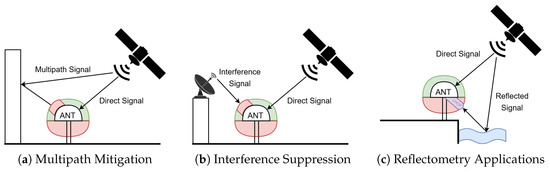
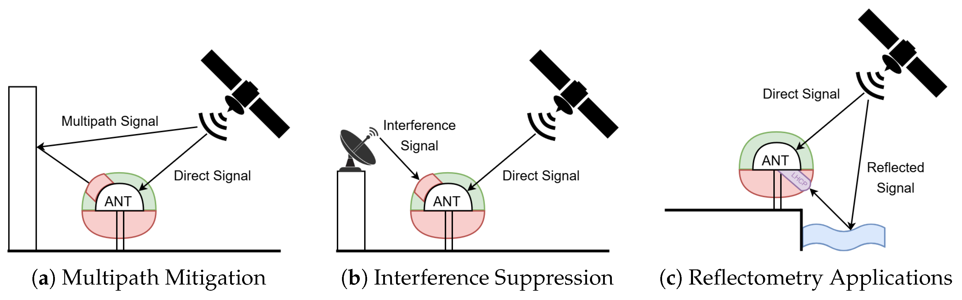
Antenna arrays can be used in the GNSS to obtain improved performance compared to single-radiator antennas (also called fixed-radiation-pattern antennas), in particular for multipath and interference suppression. Multipaths, i.e., the reception of satellite signals not only from line of sight (LOS) but also after reflection off nearby objects, poses a significant problem in terms of the achievable positioning accuracy of GNSS receiver systems, as it induces overestimation of the measured distance to the satellite (due to the additional length of reflected paths). Some techniques to mitigate multipath reception and/or its effects can be implemented on the receiver side, such as the use of multi-correlator architectures [1]. Other techniques aim to suppress multipaths at the physical level, e.g., placing a null in the direction of the most relevant reflecting objects, by means of structures external to the antennas [2] or by means of beamforming/nulling with multiantenna systems. Similarly, the nulling capability of multiantenna systems is also very beneficial to counteract jamming or spoofing [3,4]. The capability to form nulls and/or steer beams can also be useful in GNSS reflectometry applications, where the correlation between simultaneously received direct LOS transmissions and corresponding coherent surface reflections (non-LOS) can give information about environmental conditions, such as water boundaries, flood risk, wave heights, and snow depth [5,6]. All three applications (shown in Figure 1) can indeed strongly benefit from the capability of antenna arrays. However, fully adaptive CPRAs (controlled reception pattern antennas) are often characterized by high complexity and costs [7]. In some specific cases, such as installation in GNSS reference stations, it can be sufficient to have “reconfigurable” fixed pattern antennas, i.e., antenna systems (eventually made of multiple radiators) capable of reconfiguring the pattern according to the needs of specific scenarios and fixing it, i.e., not adapting it continuously as in a fully adaptive multiantenna system. Towards this scope, this work shows the design and implementation of a reconfigurable analog beamformer usable for various types of ground station GNSS antenna arrays, able to alter the antenna’s circularly polarized beam pattern in accordance with specific, a priori defined pattern masks by modifying the complex weights of each signal path and applicable (but not limited) to the above-mentioned scenarios.
Figure 1.
Three use cases of reconfigurable beamforming.
Analog Beamforming
Analog beamforming describes the process of influencing the individual amplitudes and phases of a signal in the RF domain before it is radiated by the array antennas, i.e., on the hardware and not on the software side. This is often implemented using so-called beamforming networks, consisting of transmission lines, switches, couplers, and phase shifters (e.g., Butler-, Blass- and Nolan-Matrix) [8]. Additionally, reconfigurable analog beamforming can be implemented using amplifiers, attenuators, and phase shifters to achieve more precise control over the antenna pattern. Currently, analog beamforming is seeing a renewed interest, for instance, as a low-cost, low-complexity alternative to digital beamforming or in next-generation wireless networks such as 6G systems, coupled with digital beamforming in hybrid beamforming concepts. For example, in [9], a hybrid beamforming network approach employing a Butler matrix before the digital beamforming is implemented, which enables satellite tracking in interference scenarios.
In [10], a dual-band switched-beam microstrip array for GNSS ocean reflectometry and remote sensing is introduced, which has the advantage of a very simple architecture at the cost of lower flexibility. Alternatively, in [11], a switched beam network able to turn antenna elements on and off is introduced and shown to be effective for anti-jamming. In [12], a closed-loop calibrated beamformer is presented and implemented, producing amplitude and phase errors below dB and 3°, respectively.
The argument for the reconfigurable analog beamformer like that presented in this paper comes from its high degree of freedom, coming close to the flexibility of digital beamformers, while still remaining at a lower price and complexity.
The rest of this article is structured as follows: in Section 2, the channel design and schematic of the beamformer are laid out. In Section 3, the control software is presented. In Section 4, potential error sources are identified, and a simple calibration capable of eliminating constant errors is applied and validated. The temperature dependence of the channel output is also studied. Finally, in Section 5, a validation of the beamformer operation, in the form of an exemplary radiation pattern, is presented.
2. Channel Design
The reconfigurable beamformer, used to control the RF signals, consists of 14 identical channels, each containing attenuator and phase-shifters, capable of altering the amplitude and phase of the RF signals. The 14 channels are aligned in a circular layout and split into up to seven right-hand circular-polarized (RHCP) signals and up to seven left-hand circular-polarized (LHCP) signals coming from each antenna, resulting in channels 1L to 7L and 1R to 7R. This is due to the fact that a beamformer connected to an antenna array should consider both RHCP and LHCP components because LOS GNSS signals are RHCP, while reflected multipath components are often LHCP or mixed-polarized [13,14]. Capturing both polarizations enables effective discrimination between direct and multipath signals. In any case, this can be considered an arbitrary naming convention, as the channels (L/R) are identical.
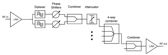
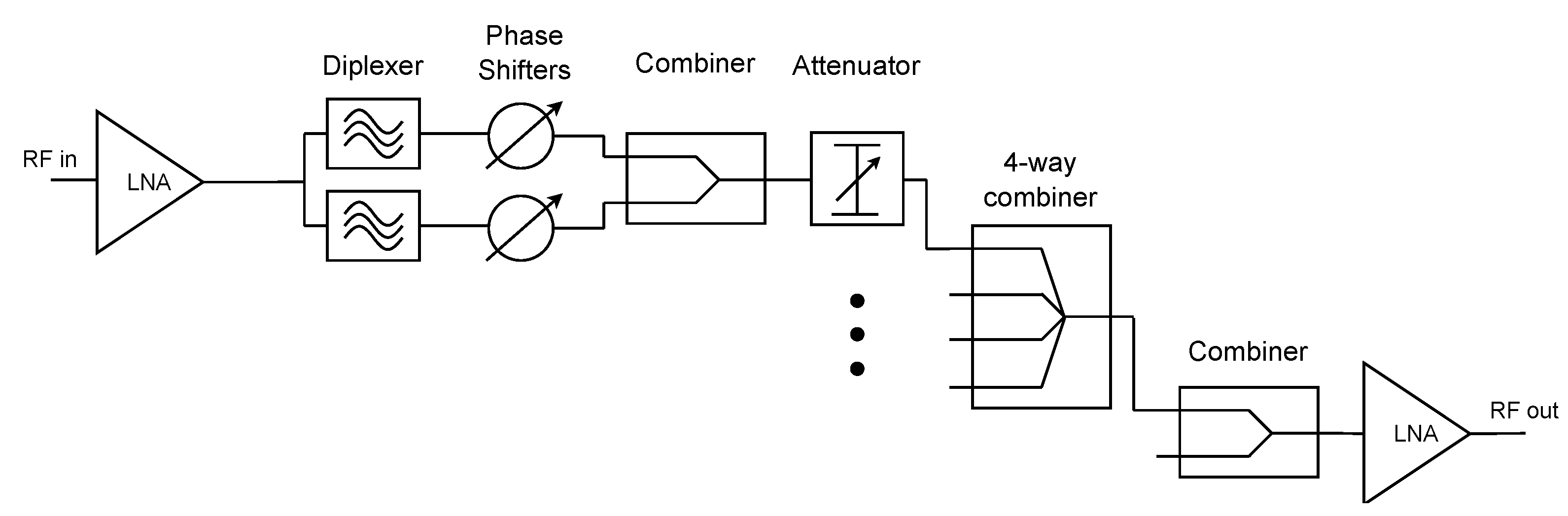
The received signals from the radiators are first pre-amplified by a high-linearity, ultra-low-noise amplifier (LNA). Afterward, a GNSS band SAW diplexer is used to isolate the lower (L5/E5a, L2, E6) and upper (L1) GNSS frequency bands.
The phases of the two signal bands are manipulated by two separate digitally controlled phase shifters adapted to the two bands. This allows the weights for the phase of the signals to be set independently for both bands in order to minimize beam and null squints in the respective bands. Following that, the signals from both bands are recombined and passed to a digitally controlled broadband RF attenuator, which allows for control over the amplitude of the signal. Next, the signals from each channel are added by means of multiple combiners. In the end, another LNA acting as a post-amp is embedded. The detailed schematics of a single channel path is provided below in Figure 2, and an exact description of the relevant used components in Section 3. The phase and attenuation values can be set with dedicated control software running on a PC, and are transferred to the beamformer over an SPI (serial peripheral interface).
Figure 2.
Block diagram of single beamformer channel.
The beamformer design is compact in size; thus, it could be placed immediately underneath an antenna array, forming an integrated reconfigurable beamforming receiver antenna system.
3. Components and Control Software
The attenuator used on the reconfigurable beamformer is HMC1122 from Analog Devices (Wilmington, MA, USA). This attenuator is able to cover an attenuation range of 0 dB to dB with a resolution of dB steps in all GNSS bands [15]. The phase shifter used on the beamformer board is PE44820 from pSemi (San Diego, CA, USA). A phase range of ° is supported, with a resolution of ° [16]. Both components allow for digital control over the SPI.
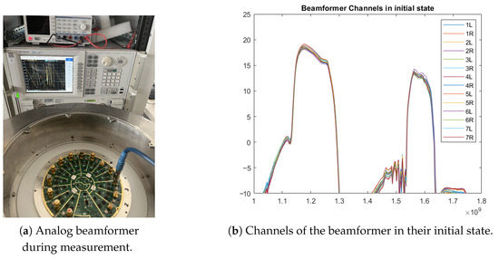
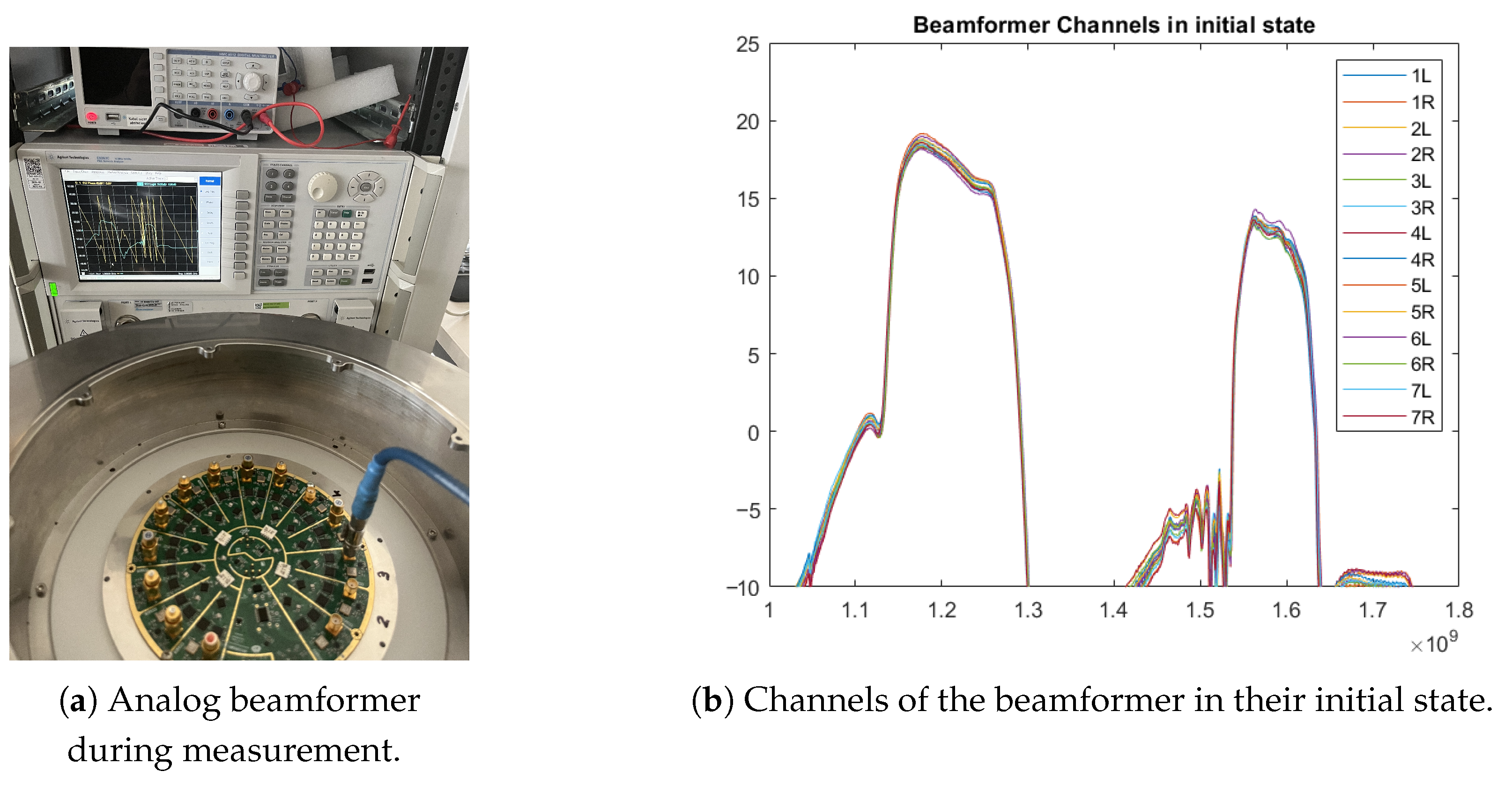
The channel characteristic, like that shown in Figure 3b, is impacted by the LNAs, with a peak gain of dB, reducing with frequency, as well as the diplexer (insertion loss (IL): dB, filter bands), phase shifters (IL: 6 dB), combiner (IL: 1 dB), attenuator (IL: dB), and the combiners (IL: 1 dB + dB).
Figure 3.
Measurement of the beamformer board.
The phase shifters and attenuators on the beamformer are controlled by an onboard microcontroller. This controller receives excitation weights in the form of one attenuation value and two phase shift values (one per frequency band) from a control PC software application and forwards the weights to all 14 beamformer channels. The communication is carried out over an SPI connection with a single command string that is passed through all mounted components in a daisy-chain manner. The communication latency and timing are on the order of 100 μs, due to the SPI and software delay. Additionally, the settling time for the components (attenuator, phase shifter) is on the order of 100 ns, which is not significantly impacting on the latency. Overall the beamforming latency is of less relevance for a reconfigurable beamformer as it is not designed for real-time adaptive beamforming.
There is also an EEPROM (electrically erasable programmable read-only memory) onboard the beamformer to which the microcontroller stores the applied control weights received from the PC software. Upon every restart of the beamformer, the controller reads the excitation command from this non-volatile memory and redistributes it to the beamformer channels since the attenuators and phase shifters, by design, do not retain the control commands when they lose power. Thus, the constructed radiation pattern is not lost, even when the beamformer is restarted. A new antenna pattern can be created only when a new command string is forwarded to the onboard microcontroller from the PC software, overwriting the old command.
The software allows a single attenuation value, but two phase weights, to be set independently for the lower and upper GNSS bands and acts purely as a control interface for previously generated weights. The inevitable discretization caused by the discrete steps of the attenuators and phase shifters is taken into account in the software, allowing only for realizable values to be set. This means that the discretization has to be taken into account when synthesizing the weights. In this work, each pattern was verified in software with actually realizable (discretized) weights before implementing it on the beamformer. In the next sections of this paper, the characteristics of the beamformer in the L1/E1 and L5/E5a bands are studied.
4. Error Sources and Calibration
4.1. Analysis of Systematic Errors
Due to imperfections stemming from the nonlinearity of phase shifters and attenuators, manufacturing differences, and coupling, the different channels of the reconfigurable beamformer board can show element-to-element variation, eventually producing sets of weights that are different from the desired values. Additionally, temperature variation and component aging also cause differences in the expected output. As a result of these errors, radiation pattern distortion, gain alterations, and null drifts are observed in measured array patterns compared to the expected patterns obtained from calculations. Thus, understanding the effects of excitation errors and the associated calibration techniques is a crucial topic, as known in the field of phased array antennas [17].
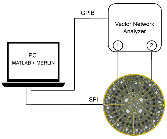
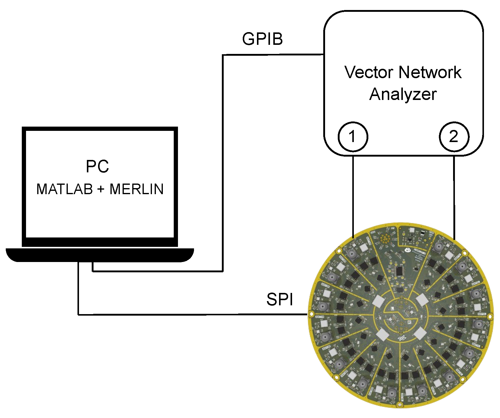
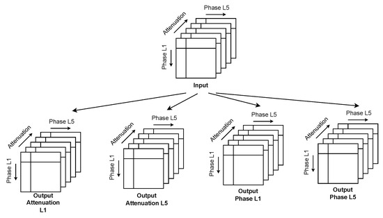
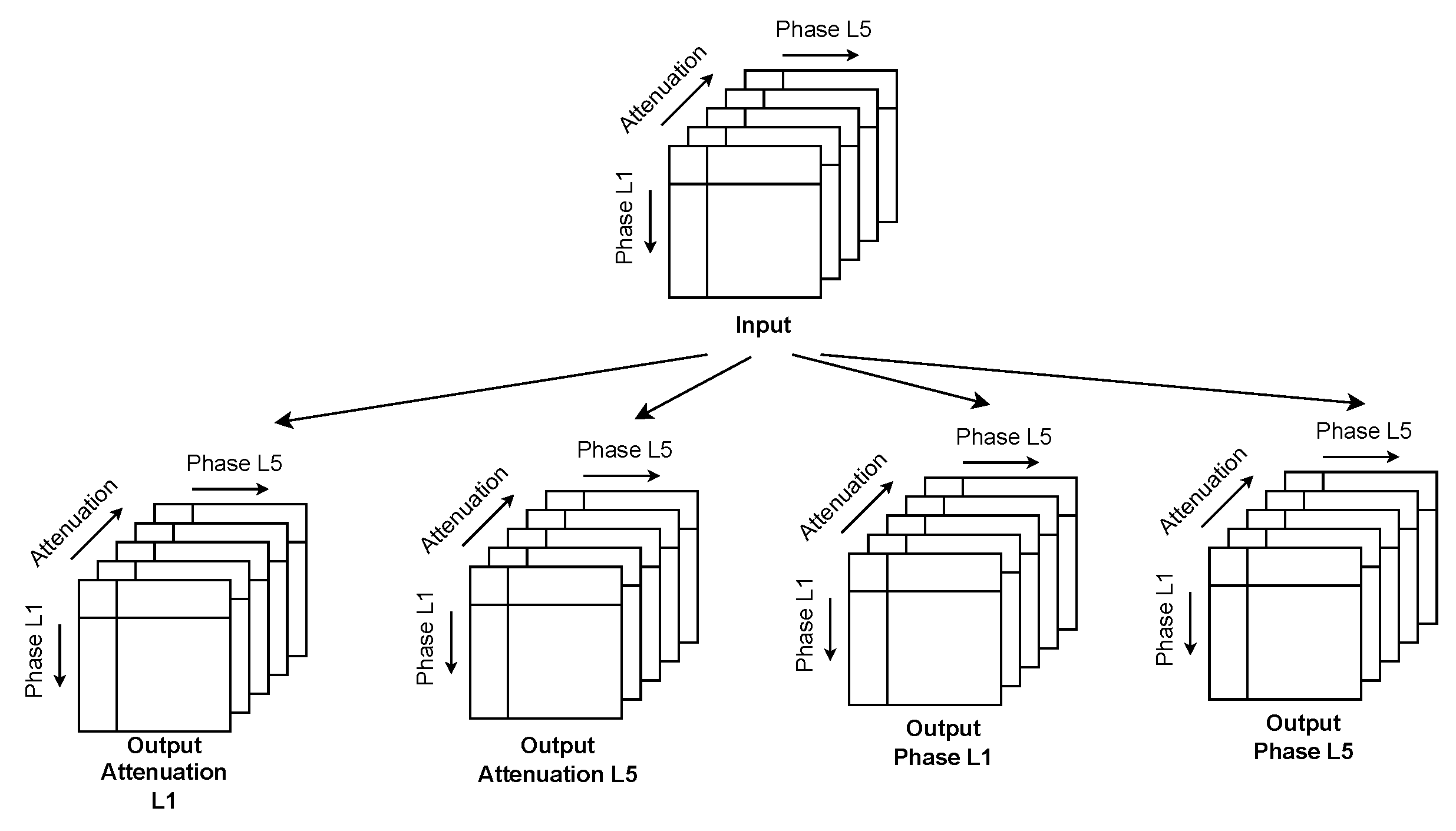
The amplitude and phase errors are measured using a PNA E8363C Vector Network Analyzer by Keysight (formerly Agilent) (Santa Rosa, CA, USA). Measurements are taken in a frequency range of 1 GHz to 2 GHz to include both the E1/L1 and E5a/L5 bands. The measurement setup is shown in Figure 3a and Figure 4, and the channel’s initial state is shown in Figure 3b. Now, three exemplary channels of the reconfigurable beamformer (Channels 1R, 2R, and 1L) are measured in a multitude of states in order to analyze their relationship. Then, as the metric of interest is indeed not the behavior of the individual channels but their relative difference, the measured channel values are subtracted from each other, where the beamformer Channel 1R is taken as a reference. In this way, the relative differences, short , can be observed. To observe the effects of the three altered input parameters, namely Attenuation, Phase L1, and Phase L5, on the four output parameters (Output Attenuation L1, Output Attenuation L5, Output Phase L1, and Output Phase L5), one obtains four three-dimensional output matrices (Figure 5). In theory, the best calibration would be to have an accurate measurement of each channel in each possible state. This is not practical; therefore, the channel measurements shall be analyzed for systematic errors.
Figure 4.
Setup of the measurement of different channel states.
Figure 5.
Setup of the measurement of different channel states and generation of lookup tables.
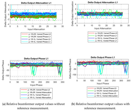
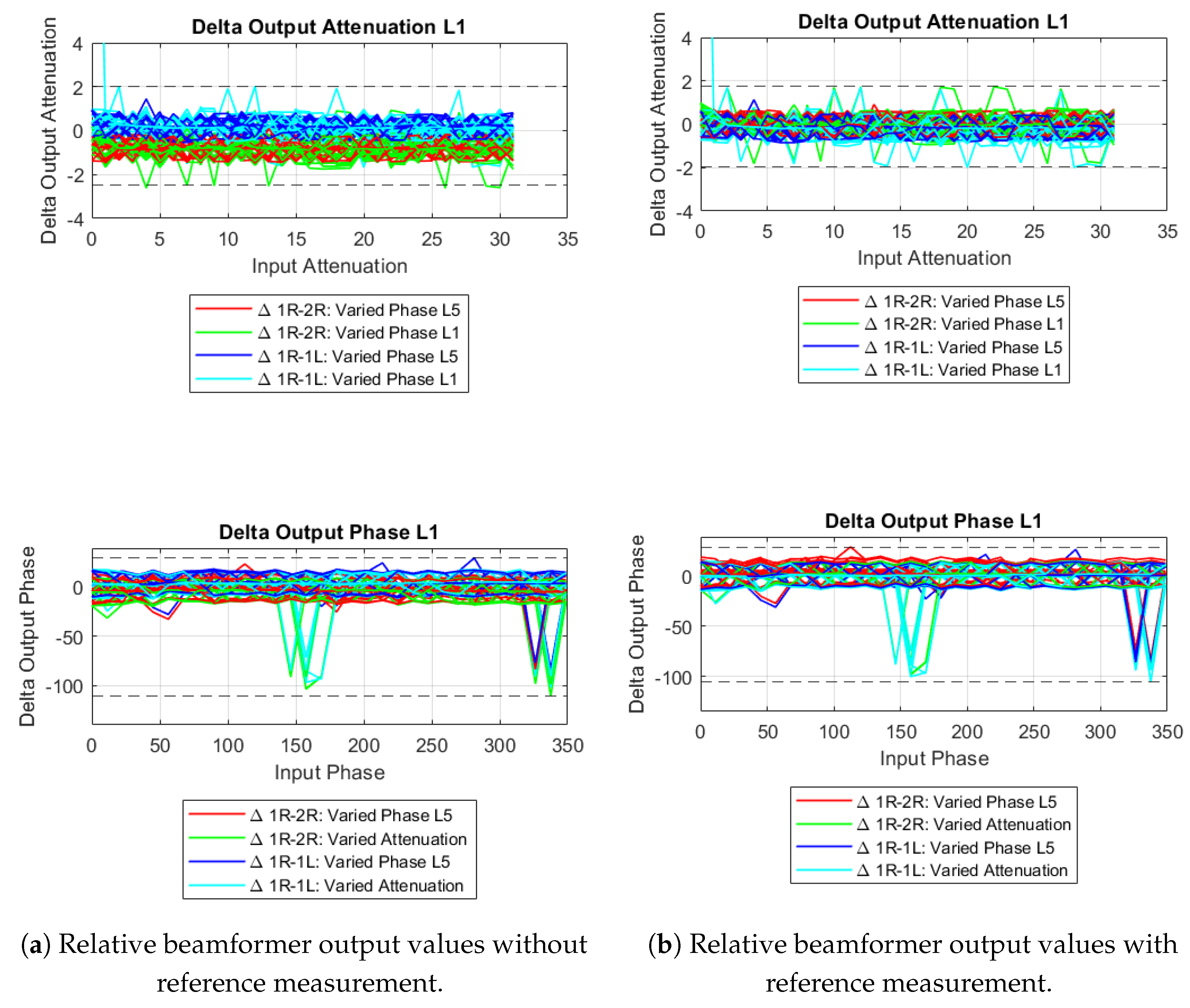
The results from the channel measurements (Figure 6a) show a systematic offset in the attenuation and indeed suggest that a calibration compromise could eliminate the need to measure all 14 channels at h/channel, or even all possible combinations of channels at an estimated 500 h total, by measuring only a single channel fully while registering only a single state measurement for all other channels. The between the respective single-state measurements and the reference channel can be used as a constant offset to achieve a simplified full characterization of the reconfigurable beamformer in the form of a lookup table, as shown in Figure 6b, where the attenuation values are now centered around 0 dB and the phases around 0°, with the exception of some outliers. A statistical analysis of the root-mean-square (RMS) difference showed a reduction from dB to dB for the amplitude and 7° to ° for the phase. Due to the fact that the error source stemmed mostly from the attenuation, the phase results did not change significantly.
Figure 6.
Comparison of beamformer output values (a) without and (b) with the reference measurement calibration, minimum and maximum values marked with grey dashed line.
A limitation of this calibration is its sensitivity to statistical outliers, as well as the assumption of linear channel similarity, which does not correct for nonlinear channel differences.
4.2. Temperature Dependence
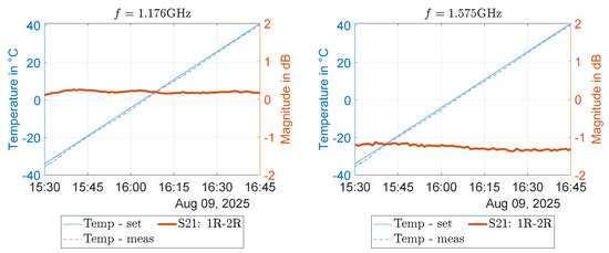
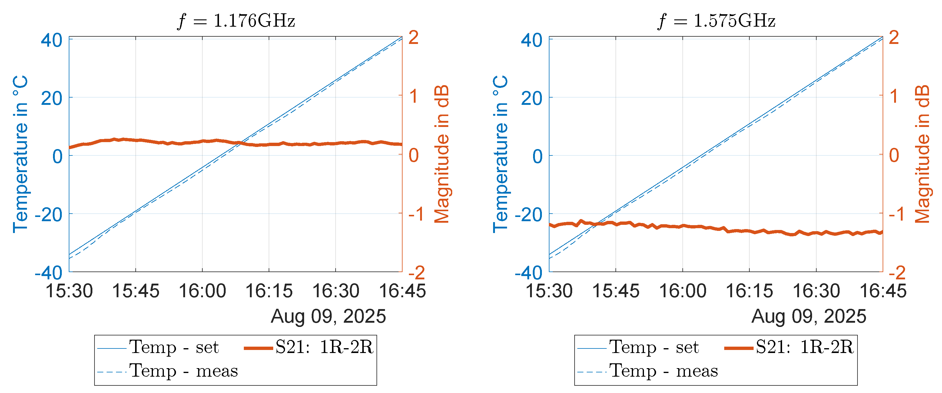
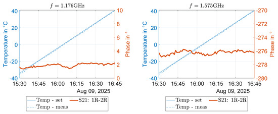
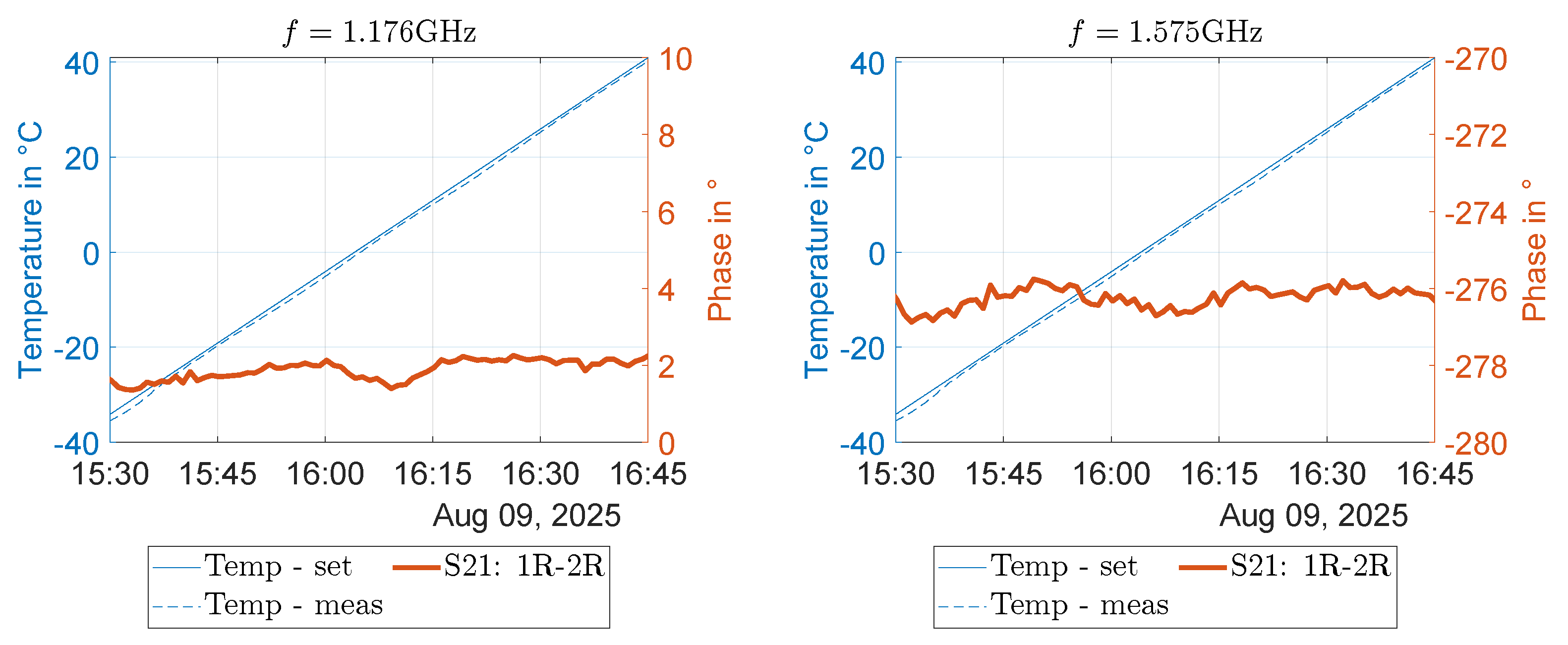
To determine the temperature dependence of the beamformer channels, the board was measured while inside an ACS DY110C thermal chamber during a temperature gradient cycle. A temperature range from °C to 40 °C was evaluated. This temperature range was chosen due to the installation scenario of GNSS reference stations and was deemed fitting. When comparing the measured channels 1R and 2R, it is apparent that the shift between the channels (i.e., the difference in amplitude and phase) remains relatively constant over the temperature range, e.g., in the range of dB and 1° (Figure 7 and Figure 8).
Figure 7.
Channel 1R and 2R amplitude differences over temperature at E1 and E5a center frequencies.
Figure 8.
Channel 1R and 2R phase differences over temperature at E1 and E5a center frequencies.
The amplitude and phase shifts are likely, to the largest extent, to be caused by the impacted LNA performance with increasing temperature, and as each channel employs identical components, the temperature dependence should not be considered a major problem for the use case of analog beamforming. Damage to the components due to long-term outdoor operation and temperature changes is unlikely, as the temperature change is more gradual in reality and within component specifications.
5. Validation
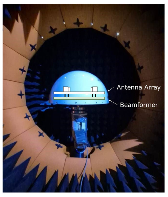
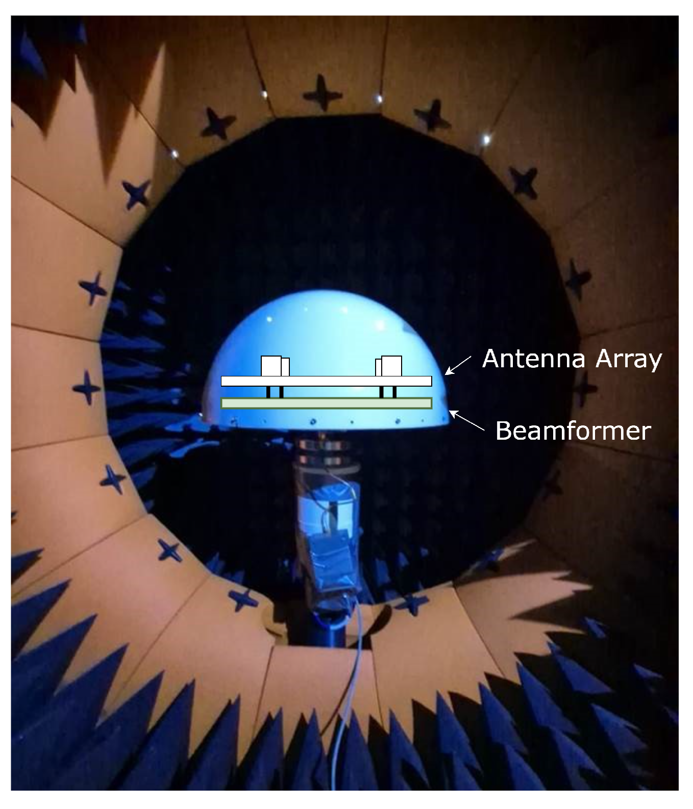
In order to demonstrate the validity of the simplified calibration approach, weights capable of generating an exemplary pattern are found for a four-element antenna array [18]. For this example, we aim to place a null in the region of azimuth 285° and elevation 50°. The theoretically obtained weights are then applied in the beamforming board and the overall obtained radiation pattern of the array connected to the board is measured in an MVG Starlab near-field anechoic chamber available at the DLR premises. In Figure 9, the measurement setup in the anechoic chamber is shown, including the antenna with a radome, and the beamformer board embedded in the mounting structure. Therefore, the beamformer board is connected to the individual antenna elements as its inputs, combines them, and outputs a single signal, which is then connected to the anechoic chamber’s input.
Figure 9.
Anechoic chamber measurement setup.
In Table 1, the weights directly from the output of the optimization algorithm are compared with the adjusted output weights gained form the calibration (from Section 4.1), as well as the input weights which produce them. It can be clearly seen that both the phase and amplitude weights are subject to an offset, and the resulting values very closely match the optimized weights. Here, more importance was given to matching the phase weights, as these impact the resulting pattern drastically.
Table 1.
Comparison of optimized, output, and input variables.
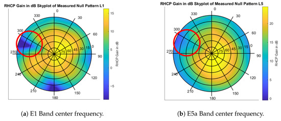
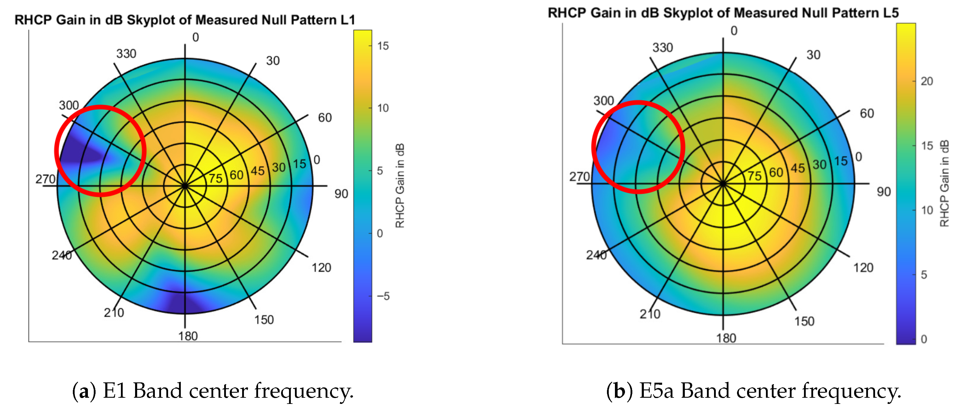
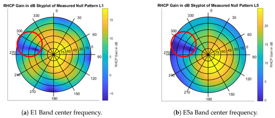
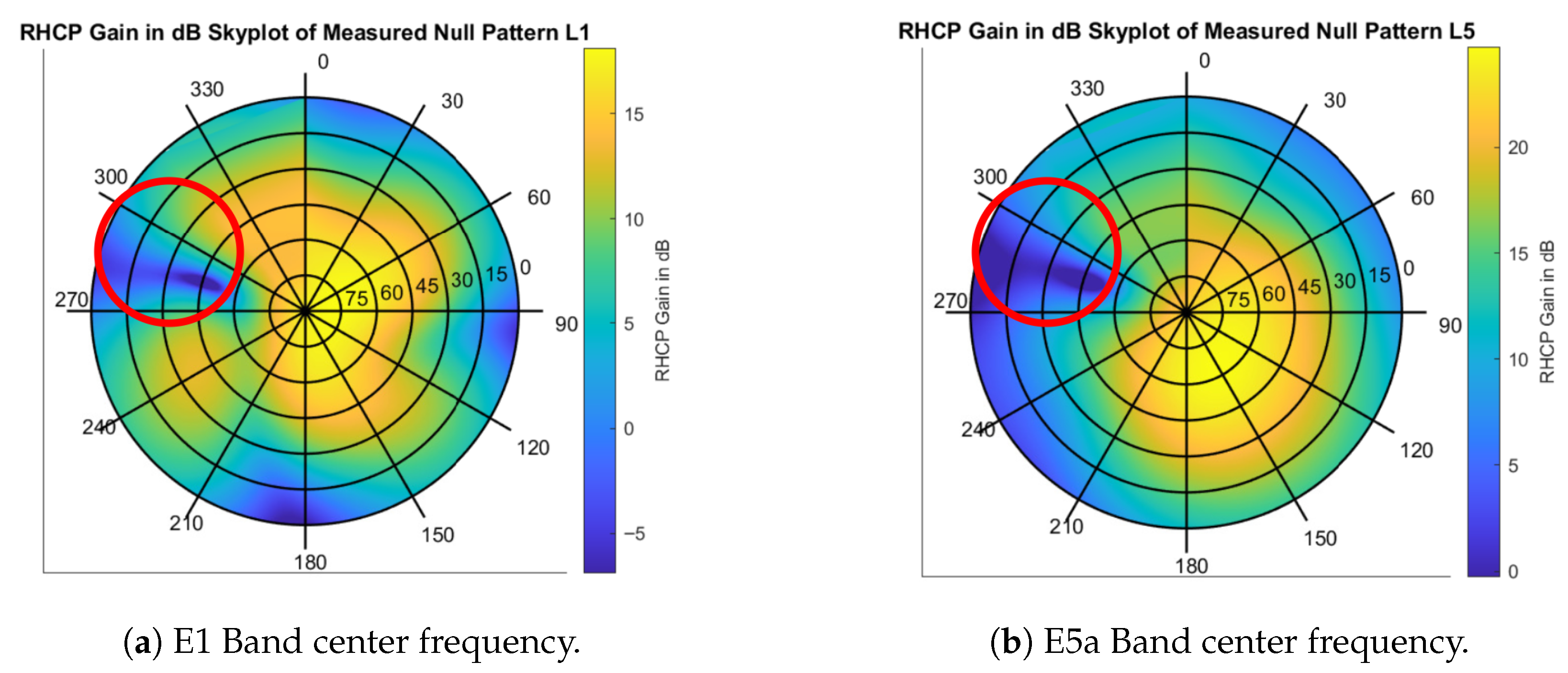
Two radiation pattern measurements are performed separately: without calibration and with the simplified calibration proposed above. The results can be seen in Figure 10 and Figure 11, where it can be easily noticed that, applying the calibration, the quality of the directive null targeting the area marked by the red circle increases substantially, especially in the E5a band. Additionally, the null depth increases from dB (from maximum) for E1 and dB for E5a, to dB for E1 and dB for E5a. While the calibration significantly impacted the null depth, the other areas of the pattern remained constant. Compared to some existing solutions like that mentioned in Section “Analog Beamforming”, the reconfigurable analog beamformer board achieves a similar and higher null depth while providing more flexibility and degrees of freedom. In comparison to [11], where the authors presented a switched beamforming network with similar scope to our concept, their implementation is evidently limited in degrees of freedom. Additionally, compared to the analog beamformer presented in [12], which implemented inline calibration, the reference measurement calibration method implemented in this work achieves similar performance with less complex architecture.
Figure 10.
Skyplots of the measured radiation pattern without calibration.
Figure 11.
Skyplots of the measured radiation pattern with calibration.
6. Conclusions
A reconfigurable 14-channel analog beamformer suited for all GNSS frequency bands was developed and tested. The single channels of the board were explained and characterized in the GNSS E1/L1 and E5/L5 bands. A simple calibration using a single reference measurement was applied and proven to improve result quality in a practical way, by evaluating the resulting radiation pattern of a connected antenna array.
Author Contributions
Conceptualization, S.C., E.O.A. and I.K.; hardware implementation, E.O.A.; software, I.K.; validation, I.K. and V.T.; data curation, I.K.; writing—original draft preparation, I.K. and S.C.; writing—-review and editing, I.K. and S.C.; visualization, I.K.; supervision, V.T. and S.C.; project administration, S.C.; funding acquisition, S.C. All authors have read and agreed to the published version of the manuscript.
Funding
The work presented in this paper has been partly performed under the project MAESTRO, funded by Deutsche Forschungsgemeinschaft (DFG), Grant number 470510446, GZ CA 2707/2-1.
Data Availability Statement
The original contributions presented in this study are included in the article. Further inquiries can be directed to the corresponding author.
Acknowledgments
The authors thank Wahid Elmarissi for conducting the measurements in the anechoic chamber.
Conflicts of Interest
The authors declare no conflicts of interest.
References
- Siebert, C.; Konovaltsev, A.; Meurer, M. Development and validation of a multipath mitigation technique using multi-correlator structures. Navigation 2023, 70, navi.609. [Google Scholar] [CrossRef] [Scilit]
- Caizzone, S.; Gerguis, R.A.; Addo, E.O.; Hehenberger, S.P.; Elmarissi, W. Spatial filtering of multipath at GNSS reference stations through metamaterial-based absorbers. IEEE Trans. Aerosp. Electron. Syst. 2023, 59, 7764–7771. [Google Scholar] [CrossRef] [Scilit]
- Caizzone, S.; Schönfeldt, M.; Elmarissi, W.; Circiu, M.S. Antennas as precise sensors for GNSS reference stations and high-performance PNT applications on earth and in space. Sensors 2021, 21, 4192. [Google Scholar] [CrossRef] [Scilit] [PubMed]
- Rados, K.; Brkic, M.; Begusic, D. Recent Advances on Jamming and Spoofing Detection in GNSS. Sensors 2024, 24, 4210. [Google Scholar] [CrossRef] [Scilit] [PubMed]
- Tabibi, S.; Geremia-Nievinski, F.; van Dam, T. Statistical comparison and combination of GPS, GLONASS, and multi-GNSS multipath reflectometry applied to snow depth retrieval. IEEE Trans. Geosci. Remote Sens. 2017, 55, 3773–3785. [Google Scholar] [CrossRef] [Scilit]
- Wang, X.; He, X.; Song, M.; Jia, D. Estimation of water boundaries and evaluation of flood risk for a reservoir using GNSS multipath reflectometry. GPS Solut. 2024, 28, 11. [Google Scholar] [CrossRef] [Scilit]
- Cuntz, M.; Konovaltsev, A.; Meurer, M. Concepts, development, and validation of multiantenna GNSS receivers for resilient navigation. Proc. IEEE 2016, 104, 1288–1301. [Google Scholar] [CrossRef] [Scilit]
- Shallah, A.B.; Zubir, F.; Rahim, M.K.A.; Majid, H.A.; Sheikh, U.U.; Murad, N.A.; Yusoff, Z. Recent developments of Butler matrix from components design evolution to system integration for 5G beamforming applications: A survey. IEEE Access 2022, 10, 88434–88456. [Google Scholar] [CrossRef] [Scilit]
- Sengupta, N.; van der Merwe, J.R.; Koelpin, A.; Rügamer, A.; Kuhl, M.; Felber, W. Multibeam antenna array and software switching for low-complexity low-cost GNSS beamforming. In Proceedings of the 2021 International Conference on Localization and GNSS (ICL-GNSS), Tampere, Finland, 1–3 June 2021; pp. 1–7. [Google Scholar]
- Maqsood, M.; Gao, S.; Brown, T.; Unwin, M.; de vos Van Steenwijk, R.; Xu, J.; Underwood, C. Low-cost dual-band circularly polarized switched-beam array for global navigation satellite system. IEEE Trans. Antennas Propag. 2014, 62, 1975–1982. [Google Scholar] [CrossRef] [Scilit]
- Shepov, V.N.; Vladimirov, V.M.; Markov, V.V. Few-element active antenna arrays for high-accuracy anti-jamming GLONASS/GPS receivers. In Proceedings of the 2015 12th International Conference on Telecommunication in Modern Satellite, Cable and Broadcasting Services (TELSIKS), Nis, Serbia, 14–17 October 2015; pp. 176–179. [Google Scholar] [CrossRef] [Scilit]
- Fabiani, B.M.; Oliveira, F.F.; Vieira, J.M.; Sakomura, E.S.; Silveira, E.S.; Nascimento, D.C.; Ferreira, D.B. Closed-loop controlled microwave beamformer. Int. J. RF Microw. Comput.-Aided Eng. 2022, 32, e23020. [Google Scholar] [CrossRef] [Scilit]
- Caizzone, S.; Circiu, M.S.; Elmarissi, W. GNSS reconfigurable antenna design for multipath characterization. In Proceedings of the ION GNSS+, St. Louis, MO, USA, 20–24 September 2021; pp. 3804–3811. [Google Scholar] [CrossRef] [Scilit]
- Addo, E.O.; Caizzone, S. Characterizing GNSS multipath in challenging installation scenario using combined simulation-measurements of dual-polarization antennas. In Proceedings of the 2023 International Technical Meeting of the Institute of Navigation, Long Beach, CA, USA, 24–26 January 2023; pp. 799–807. [Google Scholar] [CrossRef] [Scilit]
- Analog Devices. HMC1122: 0.1 GHz to 6.0 GHz, 0.5 dB LSB, 6-Bit, Silicon Digital Attenuator; Revision 0: Initial Version; Analog Devices: Wilmington, MA, USA, 2016. [Google Scholar]
- pSemi Corporation. PE44820: UltraCMOS RF Digital Phase Shifter 8-Bit, 1.7–2.2 GHz; pSemi Corporation: San Diego, CA, USA, 2018. [Google Scholar]
- He, G.; Gao, X.; Zhang, R. Impact Analysis and Calibration Methods of Excitation Errors for Phased Array Antennas. IEEE Access 2021, 9, 59010–59026. [Google Scholar] [CrossRef] [Scilit]
- Tripathi, V.; Hehenberger, S.P.; Elmarissi, W.; Caizzone, S. Multiantenna System for Robust and Precise GNSS Reference Station Performance. In Proceedings of the ION GNSS+, Baltimore, MD, USA, 8–12 September 2025. [Google Scholar]

Disclaimer/Publisher’s Note: The statements, opinions and data contained in all publications are solely those of the individual author(s) and contributor(s) and not of MDPI and/or the editor(s). MDPI and/or the editor(s) disclaim responsibility for any injury to people or property resulting from any ideas, methods, instructions or products referred to in the content. |
© 2026 by the authors. Licensee MDPI, Basel, Switzerland. This article is an open access article distributed under the terms and conditions of the Creative Commons Attribution (CC BY) license.