


Abstract
An N-port-network method is presented for the inverse design of anisotropic metasurface absorbers. Internal discrete ports and four external transverse-electric (TE) and transverse-magnetic (TM) Floquet ports retain angle-dependent reference impedances and co- and cross-polarized responses. The third-generation nondominated sorting genetic algorithm (NSGA-III) searches port states and lumped-element choices. A planar metal-backed absorber with a nominal substrate thickness of 3.2 mm is designed over 5.2–5.9 GHz. Full-wave results satisfy an absorption ratio (AR) of at least 0.8 over approximately 5.24–6.03 GHz for both polarizations at the sampled incidence angles from 0° to 74° in the specified incidence plane. At 5.5 GHz, the incidence-plane azimuth sweep satisfies this threshold at all sampled azimuths up to incidence. A prototype gives a reflection-derived AR of at least 0.8 over 5.2–5.9 GHz for both polarizations at , , and . These finite-distance measurements are subject to illumination, collection, and normalization uncertainty and do not establish calibrated total absorption at grazing incidence.
1. Introduction
Artificial electromagnetic metamaterials and metasurfaces manipulate electromagnetic waves through engineered periodic structures [1]. Depending on the unit-cell configuration, they support frequency-selective transmission and reflection, polarization conversion, absorption, energy harvesting, and programmable wave control [2,3,4,5,6,7,8,9,10,11]. Landy et al. demonstrated a resonant metamaterial absorber using electric and magnetic responses to achieve strong microwave absorption [12]. Microwave absorption is relevant to electromagnetic attenuation, stealth, and radar-cross-section reduction. Recent studies on broadband dynamic camouflage and shape-adaptive microwave metasurfaces further illustrate the role of metasurfaces in electromagnetic stealth and wave control [13,14]. The present structure is a planar metal-backed metasurface absorber, whose absorption is determined by the co- and cross-polarized reflected powers.
Established approaches for analyzing and designing periodic electromagnetic structures include the local resonant cavity cell model [15,16], effective medium theory retrieval [17,18,19], equivalent-circuit modeling [20,21,22,23], and multilevel Green’s function interpolation [24,25], together with broader analytical and numerical design methodologies [26]. These methods provide useful physical or reduced-order descriptions under their respective assumptions. As the unit cell becomes anisotropic and incorporates multiple candidate loading positions, however, the design representation must retain polarization-coupled external responses while also accommodating discrete internal states. This combination makes direct iterative design increasingly cumbersome when each candidate configuration must be related consistently to the electromagnetic response.
Recent absorber studies have addressed low profile, broadband response, polarization behavior, and oblique incidence through a range of physical and data-assisted design strategies [27,28,29,30,31,32,33,34,35,36,37]. For example, a neural network-assisted coupled mode theory approach has been applied to rapid absorber inverse design [31], while other studies have focused explicitly on wide-angle or strongly oblique-incidence absorption [34,35,36,37]. These developments motivate a representation that can preserve the anisotropic co- and cross-polarized response while allowing discrete loading configurations to be evaluated within an optimization loop.
Microwave-network formulations provide a suitable representation of loaded periodic structures. Multiport models have been developed for active metasurfaces and reconfigurable intelligent surfaces [38,39], while quasi-one-port models describe isotropic reflective metasurfaces [40]. The isotropic frequency-selective surface (FSS) inverse-design method in [41] uses an -port network with N internal discrete ports and two external Floquet ports. For an anisotropic cell, both polarizations on each side must be retained, leading to an -port network. The four external ports describe the coupled transverse-electric (TE) and transverse-magnetic (TM) responses, while the internal ports encode local connections and lumped loads. This formulation extends the network representation to polarization-coupled absorber design.
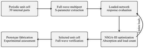
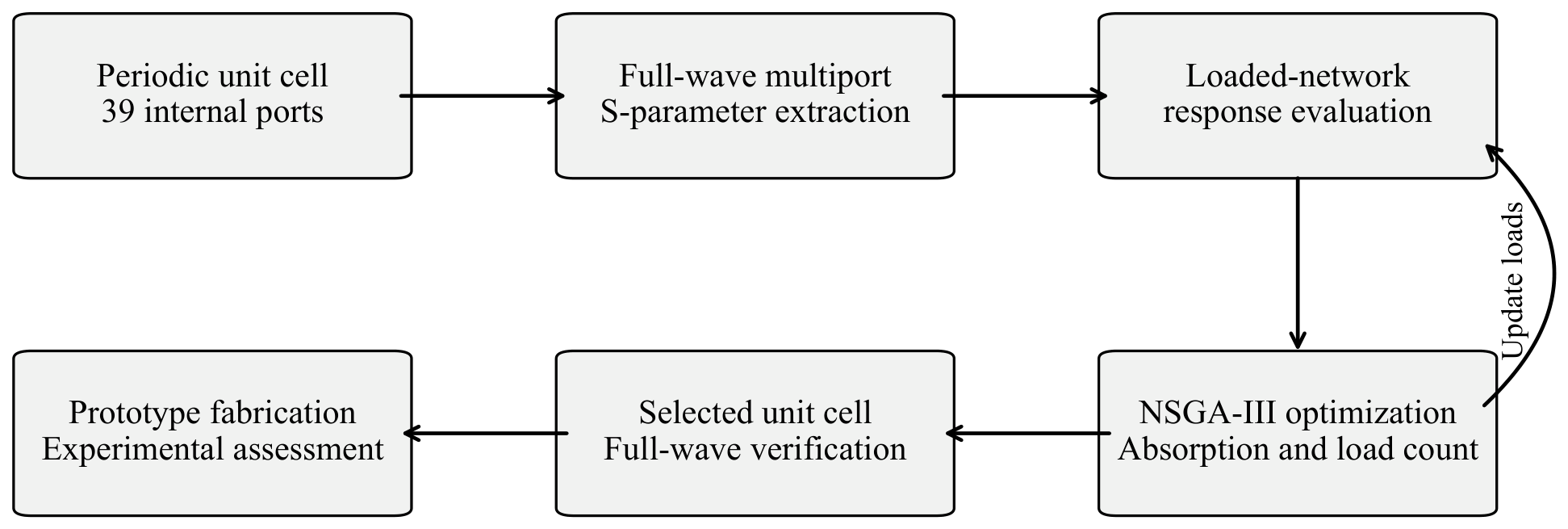
The extracted multiport response is used to evaluate candidate internal-port configurations through network equations. The network evaluator is then coupled to the third-generation nondominated sorting genetic algorithm (NSGA-III) to search the port states and loading indices. Figure 1 summarizes the sequence of electromagnetic extraction, network evaluation, optimization, full-wave simulation, and experimental assessment.
Figure 1.
Inverse-design procedure comprising multiport extraction, network evaluation, multi-objective optimization, full-wave simulation, and experimental assessment.
A planar absorber based on a polarization converter (PC) demonstrates the method. Its design interval is 5.2–5.9 GHz and nominal substrate thickness is 3.2 mm. The network objective uses and , with the retained full-wave data sample incidence angle in increments. In the specified incidence plane, the simulated common TE/TM band with absorption ratio (AR) of at least 0.8 is approximately 5.24–6.03 GHz over the sampled – range. A separate incidence-plane azimuth sweep at 5.5 GHz assesses the anisotropic angular response.
The proposed anisotropic network formulation retains four external polarization channels and couples them to a discrete search over internal-port states and lumped-element choices. The planar absorber is assessed through network calculation, full-wave simulation, and measurements at three incidence angles.
2. Numerical Characterization
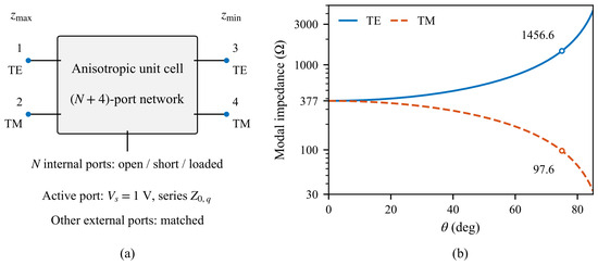
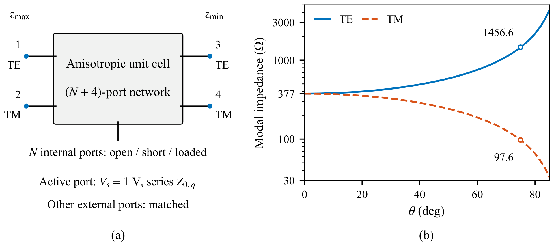
Floquet ports describe the incident and outgoing modes of the periodic structure, while internal discrete ports represent candidate connections and lumped-element locations. Figure 2a shows their arrangement in the network model.
Figure 2.
(a) Anisotropic -port network with four external Floquet ports and N internal discrete ports. The active port is driven by a 1-V Thevenin source with its modal series impedance, and the other external ports are matched. (b) TE and TM modal reference impedances versus incidence angle, plotted on a logarithmic impedance axis.
For a homogeneous free-space region, the modal reference impedances of the external Floquet ports depend on incidence angle and polarization according to
where is the free-space wave impedance and is the incidence angle. The TE and TM impedances are equal at normal incidence and diverge as the incidence becomes oblique, as shown in Figure 2b. These angle-dependent values are used directly as the reference impedances of the corresponding external modal ports.
Before optimization, discrete ports are introduced at the candidate loading positions, and the resulting multiport unit cell is characterized in CST Microwave Studio [42]. An anisotropic unit cell with N internal discrete ports is represented by an -port network whose four external Floquet ports follow the fixed order , , , and . These external ports are modal ports of the periodic problem rather than physical lumped loads.
Because the external modes generally have different reference impedances at oblique incidence, the extracted scattering matrix is converted to an impedance matrix with the diagonal port-specific reference-impedance matrix [43]
Here, is the identity matrix, is the full scattering matrix, and follows the same port ordering as . At each incidence angle, Equation (2) uses and its corresponding . For the external-port order , , , and , the external block is . The external reference impedances are at normal incidence and approximately for TE and for TM at . The remaining diagonal entries are the reference impedances of the internal discrete ports used in CST extraction.
For a specified configuration, open internal ports are eliminated by enforcing zero current. Shorted ports have zero termination impedance, while loaded ports have their prescribed complex impedances. After open-port elimination, combines the external modal terminations and the retained internal loads. The unexcited external ports are matched to their modal impedances. At the excited port, the modal impedance is the series impedance of the Thevenin source. The external block enforces these modal boundary conditions, while contains the physical internal loads. The active network is solved from
where is the port-current vector of the active subsystem and is the prescribed source vector. When external Floquet port q is excited, the source is defined independently of the unknown current as
where is the unit vector for the excited external port. With currents positive into the network, . Hence, , and the normalized scattering coefficients are independent of the nonzero source amplitude.
Let and denote the solved voltage and current subvectors of the four external ports, and let denote their real diagonal reference-impedance matrix. Following the standard power-wave convention [44], the incident and outgoing modal waves and the corresponding co- and cross-polarized coefficients are
For an external port k, and . Since only port q is excited, gives the loaded-network scattering coefficient from port q to port k. The index r denotes the orthogonal-polarization port on the incident side, and s and t denote the co- and cross-polarization ports on the opposite side. For incidence from , TE excitation uses and TM excitation uses . The side-specific port pairs are interchanged for incidence from .
For a two-sided structure, the absorbed-power fraction is . The metallic backing suppresses transmission, giving
These network quantities provide the response metrics used by the subsequent mixed-discrete inverse design. The multi-objective formulation is
Equation (7) is solved using NSGA-III [45]. The decision vector contains two entries per candidate loading position, specifying the port state and the index of a component in a finite loading set. The operator averages over the sampled frequencies and specified TE/TM cases. Thus, and minimize the negative mean logarithmic absorption at and , while minimizes the number of physical loads per unit cell.
3. Inverse Design of a PC-Based Metasurface Absorber
A polarization-converter-based planar absorber is used to demonstrate the formulation in Section 2.
3.1. Configuration of the Discretized PC-Based Unit Cell
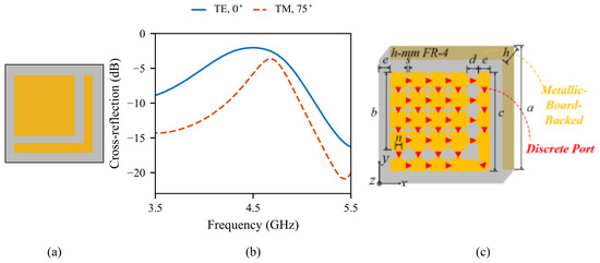
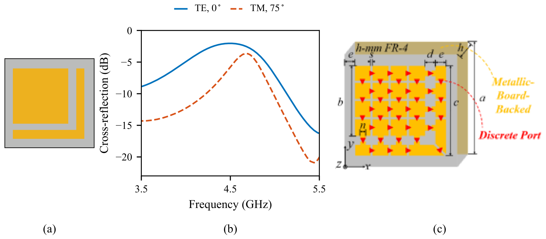
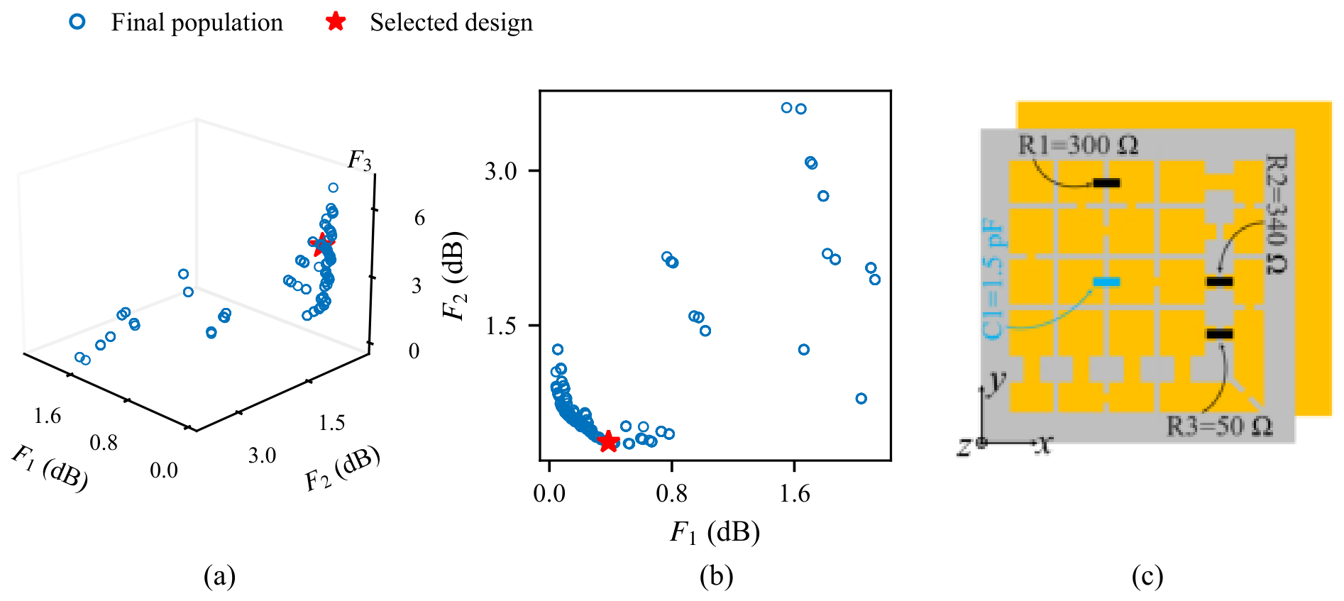
A reflective linear-to-cross polarization-converter geometry is adopted as the starting unit cell. It consists of a square patch, an L-shaped branch, and a reflective metallic board. The corresponding geometry and representative reflection responses are shown in Figure 3a,b. The unit-cell period is 20 mm. The starting structure produces a strong cross-polarized reflected response within its operating band. The selected absorber uses three resistors and one capacitor, whose values and positions are specified in Figure 4c.
Figure 3.
(a) Starting polarization-converter unit cell. (b) Cross-polarized reflection for TE incidence at and TM incidence at . (c) Discretized unit cell. Dimensions are mm, mm, mm, mm, mm, mm, mm, and mm. The copper thickness is 0.035 mm.
Figure 4.
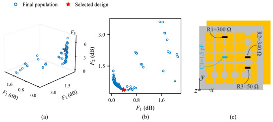
(a) Final optimization population in the –– objective space. (b) Projection onto and . The absorption objectives and are expressed in dB, and is the load count. The red star denotes the selected design. (c) Selected absorber with pF, , , and .
The starting geometry is subsequently discretized with multiple slots so that local connections and loading positions can be represented by internal discrete ports. As shown in Figure 3c, these ports are distributed on the square patch, the L-shaped branch, and the clearance between the two metallic substructures. The discretized unit cell contains 39 internal discrete ports. Together with the four external Floquet ports defined in Section 2, the electromagnetic model forms a 43-port network. The starting and discretized unit cells retain the same overall dimensions.
The unit-cell model uses nominal FR-4 parameters from the CST material library, with and held constant over the simulated frequency range. The substrate thickness is 3.2 mm. The calculations use nominal material and geometric parameters without tolerance variations.
Each candidate port is assigned an open, short, or loaded termination as defined in Equation (3). The selected design uses a nominal capacitance of 1.5 pF and resistances of 50 , 300 , and 340 , implemented with 0402 surface-mount packages. The network calculation and full-wave simulations represent these components by ideal lumped impedances without package parasitics.
The discretized unit cell is characterized using the CST frequency-domain solver for normal incidence, TE incidence at , and TM incidence at . These three extractions supply the multiport data for the network search. Each candidate is evaluated through the network equations, while subsequent full-wave simulations assess the selected design.
3.2. Numerical Optimization
The network formulation is used to search the internal-port states and loading choices. The optimization uses frequency samples from 5.2 to 5.9 GHz in 0.1 GHz steps. The absorption bandwidth is the frequency range satisfying for a specified incidence angle and polarization.
The 39 candidate internal ports give a 78-entry decision vector, comprising 39 discrete port-state variables and 39 component-index variables. Each component index selects a value from the prescribed finite loading set. NSGA-III uses a population size of 300. The initial population is generated randomly. The crossover and mutation probabilities are 1 and 0.01, respectively. The search terminates after 300 generations. Reference directions are generated using UniformPoint v20.77.0. Crossover exchanges entries between parent chromosomes at selected positions. Binary port-state entries undergo bit-flip mutation, and discrete values are rounded to integers. The reported design is obtained from a single optimization run.
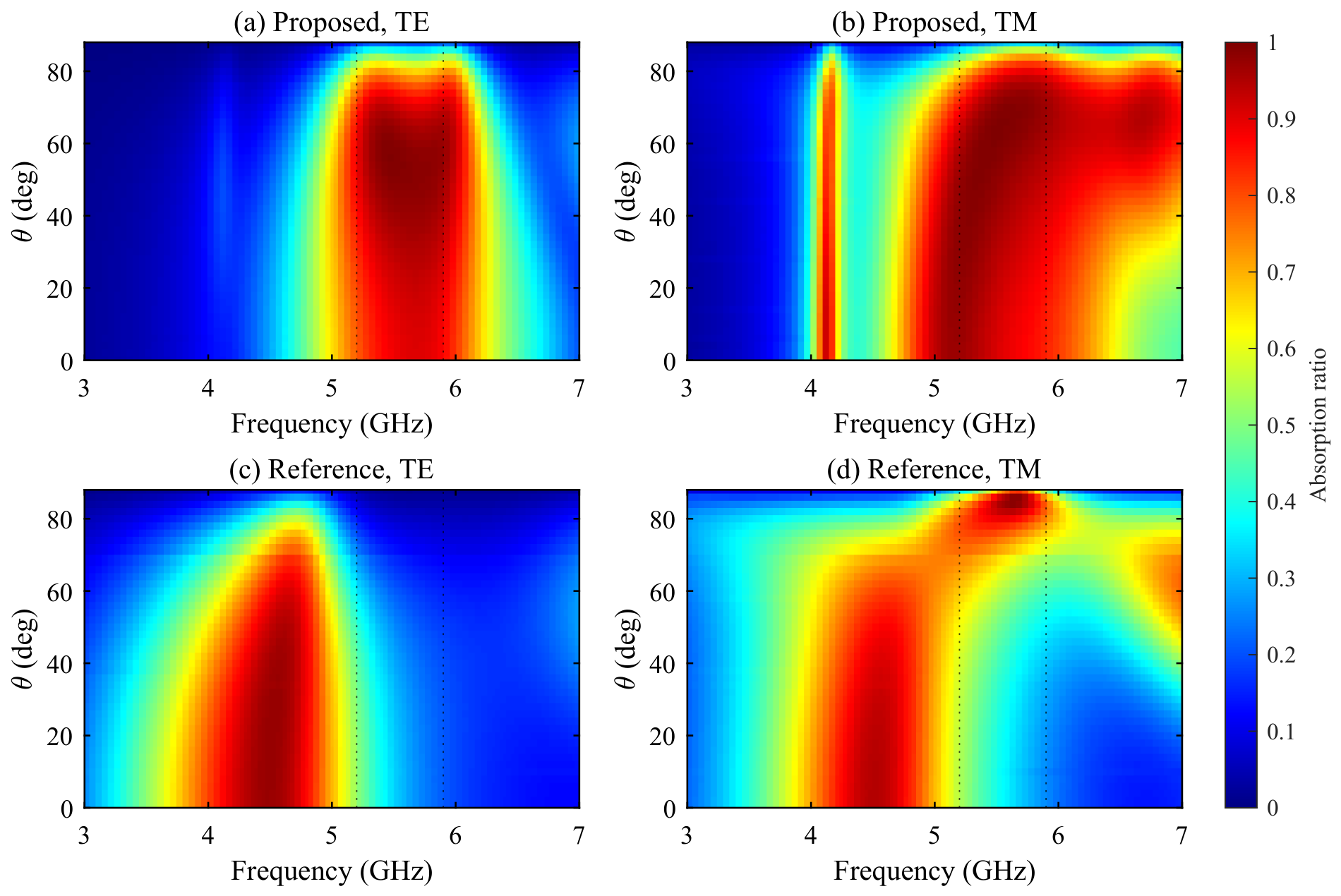
The angles and are the lower and upper boundaries of the target incidence-angle range. They represent normal and strongly oblique incidence, respectively. At normal incidence, the TE and TM modal impedances are equal, whereas they differ substantially at , as shown in Figure 2b. These representative boundary conditions define the two absorption objectives in Equation (7). Both objectives act on the same port-state and loading variables, so a candidate configuration is evaluated at both boundaries. The frequency–angle maps in Figure 5 show the resulting absorption response at the intermediate angles.
Figure 5.
Absorption ratio maps versus frequency and incidence angle. (a,b) Proposed absorber under TE and TM incidence. (c,d) Reference absorber under TE and TM incidence. The dotted lines indicate 5.2 and 5.9 GHz.
Table 1 summarizes the design variables and frequency samples.
Table 1.
Design variables and frequency sampling.
Figure 4a,b shows the final optimization population for the absorption objectives and and the load-count objective . The final design was selected by prioritizing absorption performance at the two target incidence angles, with load count treated as a secondary consideration. The selected configuration is row 15 of the archived final population, with . Figure 4c gives its physical loading configuration. This performance-prioritized selection is not expressed as minimization of the scalar sum .
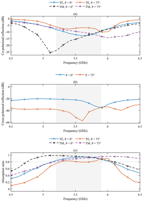
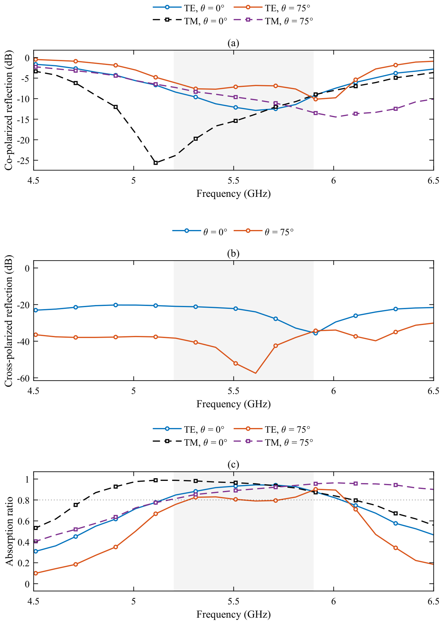
Figure 6 presents the network-calculated co- and cross-polarized reflection coefficients and the absorption ratios of the selected design, calculated using Equation (6). Table 2 reports the threshold crossings in the main absorption region, using linear interpolation between the saved plotted samples. The TE result does not maintain AR throughout 5.2–5.9 GHz. Its qualifying portions inside this interval are approximately 5.27–5.55 and 5.73–5.90 GHz. In particular, AR is 0.7903 at 5.61 GHz and 0.7949 at 5.71 GHz, with a below-threshold interval of approximately 5.55–5.73 GHz. At the lower design boundary of 5.2 GHz, the interpolated value is approximately 0.749.
Figure 6.
Network-calculated response of the selected absorber at and . (a) Co-polarized reflection. (b) Cross-polarized reflection. (c) Absorption ratio. The shaded interval denotes the 5.2–5.9 GHz design range.
Table 2.
AR intervals around the main design band, extracted from the retained plotted data.
3.3. Simulation Results
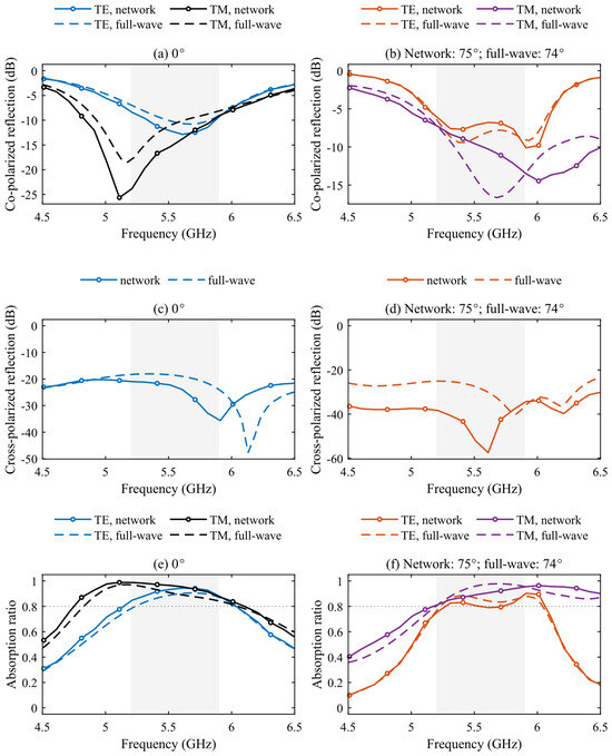
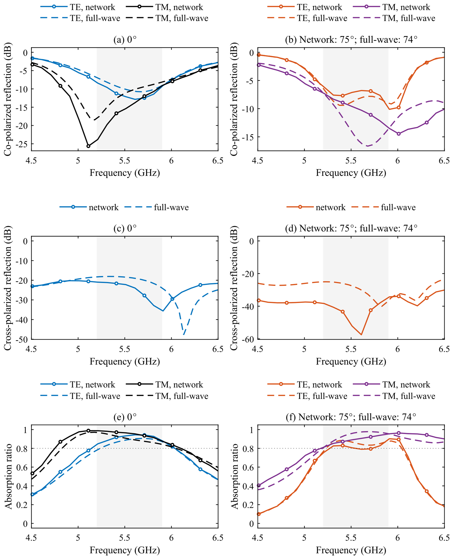
Figure 7 compares the network-calculated and full-wave co-polarized reflection, cross-polarized reflection, and absorption ratio. At , the full-wave main absorption bands are approximately 5.24–6.03 GHz for TE and 4.83–6.05 GHz for TM. At , they are approximately 5.23–6.04 GHz and 5.19–7.08 GHz, respectively. The network calculation at and full-wave simulation at are neighboring-angle checks, not an exact-angle validation. The retained full-wave exports use a angular grid. The legacy extraction index corresponds to for the proposed absorber and for the reference absorber in Figure 8, whose export also omits the row. These values reflect the archived sampling and indexing, not a solver restriction at . No full-wave curve is inferred by relabeling either result.
Figure 7.
Network-calculated and full-wave responses. (a,b) Co-polarized reflection. (c,d) Cross-polarized reflection. (e,f) Absorption ratio. Left column, normal incidence. Right column, oblique incidence at for the network calculation and for the full-wave simulation. The shaded interval denotes 5.2–5.9 GHz.
Figure 8.
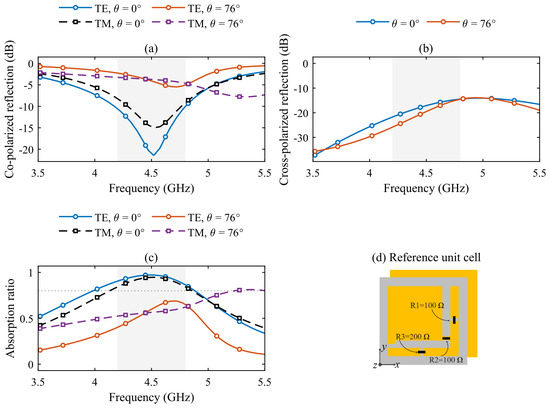
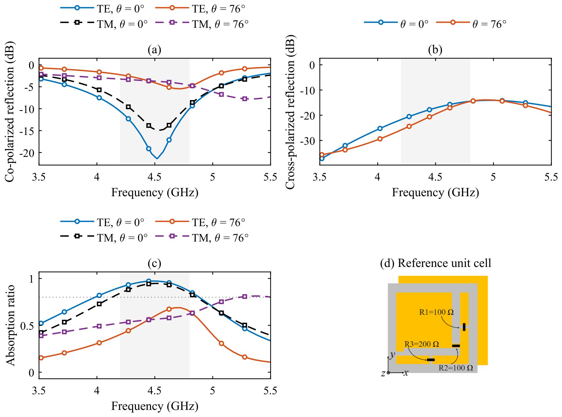
Full-wave response of the reference absorber at and . (a) Co-polarized reflection. (b) Cross-polarized reflection. (c) Absorption ratio. (d) Reference unit cell with , , and . The shaded interval denotes 4.2–4.8 GHz.
A reference absorber retains three fixed loading positions, with two on the L-shaped branch and one in the clearance, as shown in Figure 8d. Its loading values are optimized using the same network procedure. The reference absorber is optimized over 4.2–4.8 GHz with three loading positions. The proposed absorber is optimized over 5.2–5.9 GHz with 39 candidate loading positions.
Figure 5 shows the frequency–angle absorption maps of the proposed and reference absorbers under TE and TM incidence in the specified incidence plane. The common TE/TM band of the proposed absorber with AR across all retained angular samples from to is approximately 5.24–6.03 GHz. This statement applies to the sampled angles and does not establish a continuous-angle guarantee or an all-azimuth bandwidth. Figure 5b also contains a narrow TM absorption feature near 4.1 GHz that changes little in frequency with incidence angle. It is distinct from the main design band. The available loss maps cover 4.5–6.5 GHz and contain no information at 4.1 GHz. The present results therefore do not identify the physical origin of this secondary feature.
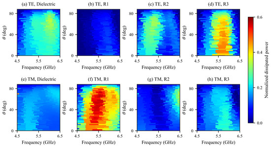
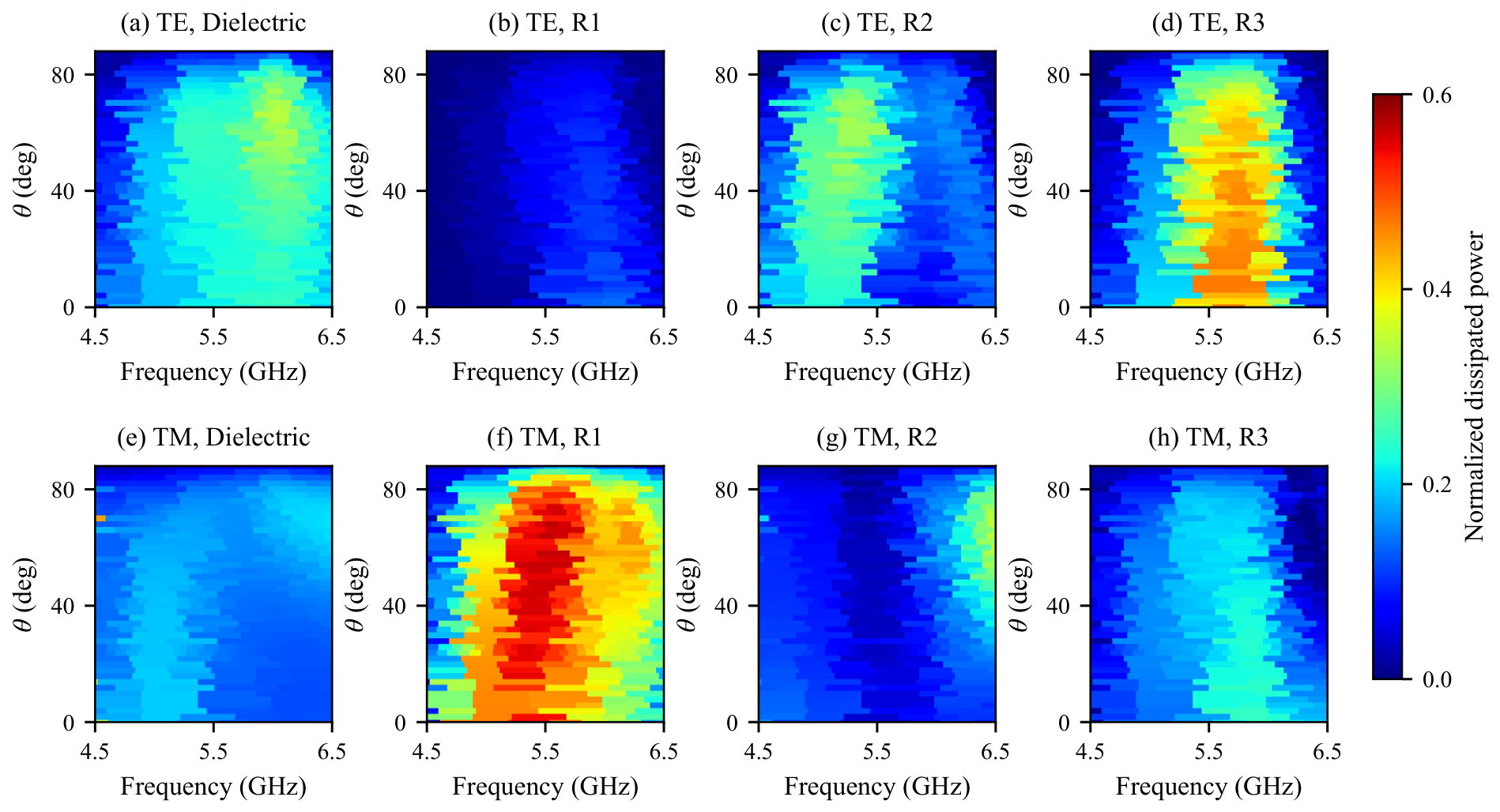
Figure 9 shows the normalized power dissipated in the dielectric and the three resistors. Under TE incidence, has the largest resistor-loss contribution and contributes little. Under TM incidence, the contribution of increases while that of decreases. All panels use a common 0–0.6 color scale. Flat cells display the native frequency and angle samples without smoothing or frequency/angle interpolation, so narrow variations retained in the maps remain features of the exported samples.
Figure 9.
Power-loss contributions normalized by the incident power. (a–d) Dielectric, , , and under TE incidence. (e–h) Corresponding contributions under TM incidence. Native samples are displayed as flat cells with a shared 0–0.6 scale.
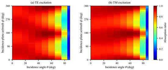
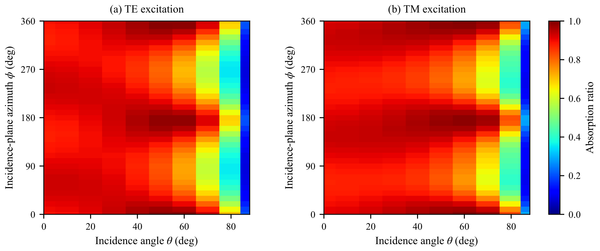
Figure 10 shows AR at 5.5 GHz versus incidence angle and incidence-plane azimuth . The angle is measured from the surface normal, and specifies the orientation of the incidence plane about that normal relative to the unit-cell x axis. TE excitation in panel (a) has its electric field perpendicular to the incidence plane, while TM excitation in panel (b) has its electric field within that plane and perpendicular to the propagation direction. The TE/TM basis therefore follows the incidence plane as varies. This is an azimuth sweep, not a rotation of linear polarization at a fixed propagation direction.
Figure 10.
Absorption ratio at 5.5 GHz versus incidence angle and incidence-plane azimuth . (a) TE electric field perpendicular to the incidence plane. (b) TM electric field in the incidence plane. The TE/TM basis rotates with the incidence plane. Flat cells represent the sampled angles.
At 5.5 GHz, AR exceeds 0.8 for both TE and TM at every sampled azimuth from to in steps for the sampled incidence angles up to . The minimum values at are 0.8029 and 0.8041 for TE and TM, respectively. At , these minima decrease to 0.7142 and 0.7356. Thus, the all-azimuth result is more restrictive than the response in the single incidence plane of Figure 5. At normal incidence, the azimuthal basis degenerates to an in-plane choice of electric-field orientation.
4. Experiment and Discussion
4.1. Experiment
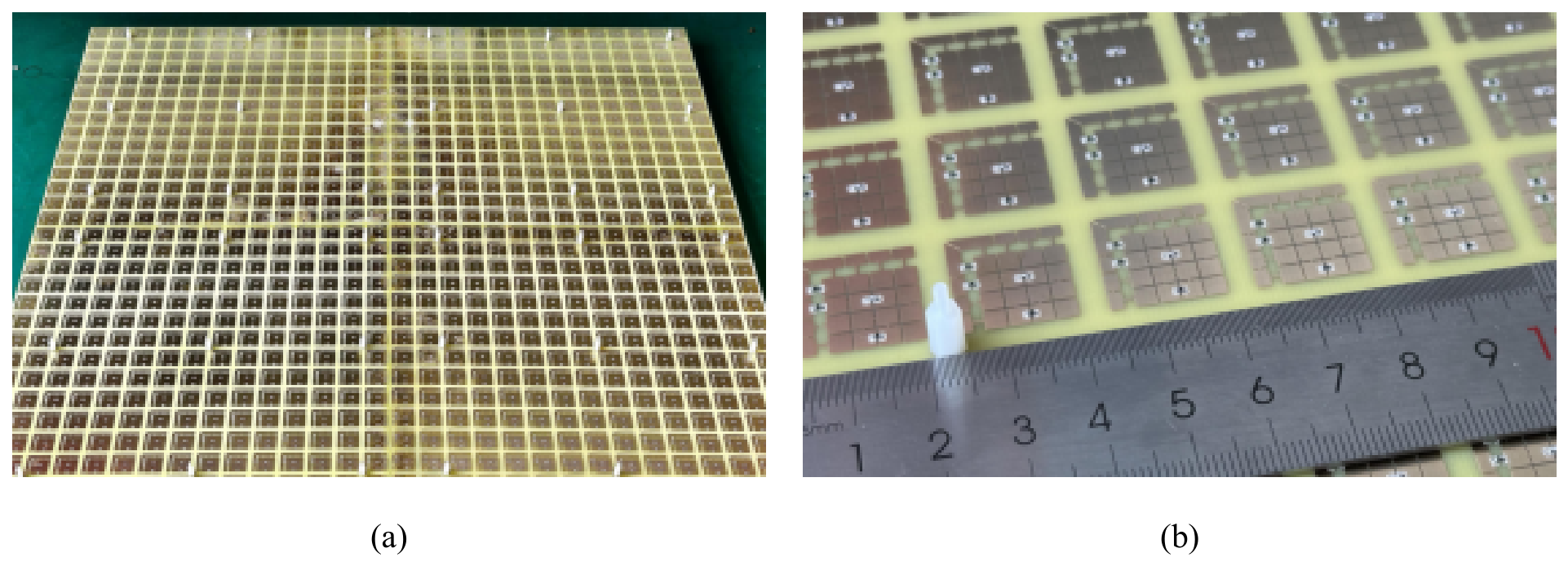
The planar prototype shown in Figure 11 comprises four panels assembled into a array with an overall size of . The patterned layer and metallic backing are fabricated on two 1.6 mm FR-4 boards held in close contact by nylon pillars. The assembly has no designed air layer and a nominal total dielectric thickness of 3.2 mm, matching the simulated stack-up. Rigid sponge strips join the four panels with narrow seams, and the lumped elements use 0402 packages.
Figure 11.
Fabricated planar absorber. (a) Overall prototype containing four panels. (b) Enlarged view of the patterned cells and 0402 lumped elements.
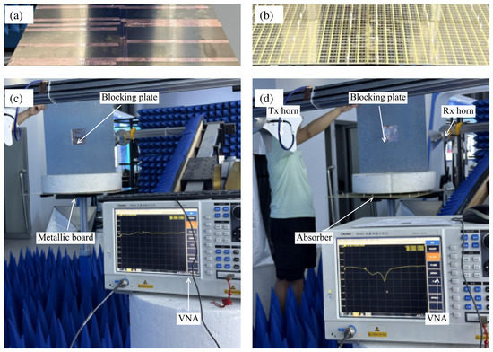
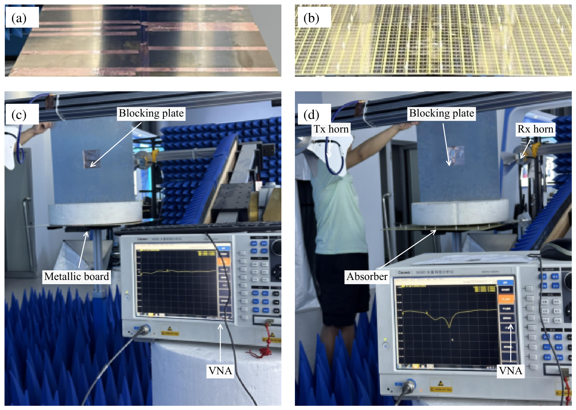
The prototype is placed on a horizontal platform surrounded by wedge-shaped absorbers. The transmitting and receiving antennas are HengDa Microwave HD-10180DRHA10S ultrawideband double-ridged horns, connected to a Ceyear 3656D vector network analyzer (VNA), with a nominal horn-to-sample distance of 1.5 m. The horns are oriented for co- and cross-polarized reception. The manufacturer specifies operation over 1–18 GHz and an E/H-plane beamwidth range of – [46]. This broadband specification is not a frequency-resolved half-power beamwidth measurement within 5.2–5.9 GHz. The mounting arrangement includes positioning arms, while Figure 12 also records an operator near the transmitting horn. A metallic board with the same dimensions as the sample is measured separately as the reflection reference.
Figure 12.
Measurement photographs at incidence. (a,b) Close views of the metallic-board reference and absorber, respectively. (c,d) Corresponding overall arrangements. The operator visible near the transmitting horn is part of the photographed setup, so these images do not document unattended acquisition. A separate foam-supported metallic plate reduces the direct horn-to-horn path. The photograph angle differs from the response reported in Figure 13.
Figure 13.
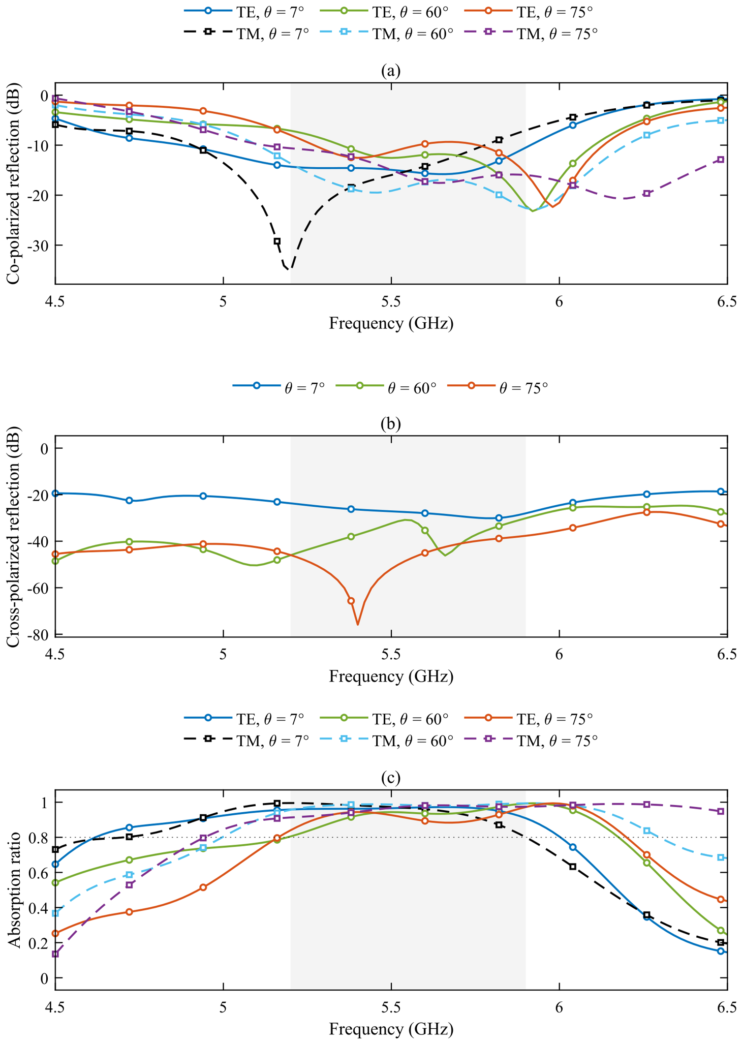
Measured response at , , and . (a) Co-polarized reflection. (b) Retained cross-polarized reflection trace for each angle. (c) Reflection-derived AR using Equation (8). The shaded interval denotes the 5.2–5.9 GHz design range. These finite-distance, normalized results have no repeatability-based error bars.
The horn-to-sample distance is 1.5 m. For the 0.6 m aperture, the Fraunhofer distance is approximately 12.5–14.2 m over 5.2–5.9 GHz.
At strongly oblique incidence, a separate metallic plate supported by foam reduces the direct horn-to-horn path. This blocking plate is distinct from the same-size board used for reflection normalization.
The receiver was scanned over elevation angles from to and azimuth angles from to , with a step in both coordinates. The time-domain reflection peak was inspected to select a 10 ns rectangular gate that retained the observed sample-return energy. A 10 ns interval corresponds to approximately 3 m of propagation-path length. This energy-based choice does not establish exclusion of returns from the blocking plate, platform, VNA, or operator if they overlap the selected interval. The reported results use this fixed gate width. Gate-width sensitivity is not quantified, and repeated acquisition was not performed.
The measured AR is obtained by angular integration of the gated reflected powers using a sine weight, followed by normalization to the metallic-board reference over the same receiver scan. For incident polarization p, the discrete expression is
Here, and are the sums of the gated co- and cross-polarized reflected powers for the sample and metallic reference, respectively. The receiver polar angle is measured from the surface normal, and is its azimuth. These receiver coordinates are distinct from the incident-wave angles. The factor accounts for the spherical solid-angle element. The increments are , expressed in radians in the quadrature, and their common product cancels in the ratio. The integration covers the measured – polar sector and – azimuth range.
The retained processing uses the same cross-polarized trace for the two incident polarizations at each angle. Its co-polarized normalization subtracts the frequency-averaged metallic-board level and includes fixed offsets of dB for TE and dB for TM at , respectively. The cross-polarized normalization subtracts the frequency-dependent reference level and includes offsets of dB. These offsets are included in the reported curves. Their calibration uncertainty is not independently quantified. Equation (8) includes angular integration over the measured sector. The unmeasured sector and finite measurement distance remain limitations on total absorbed-power estimation.
Figure 13a,b presents the normalized co- and cross-polarized reflection traces, and Figure 13c gives the corresponding reflection-derived AR. Measurements are reported only at , , and . The setting provides physical separation between the transmitting and receiving horns near normal incidence. The photographs were taken at and document the arrangement rather than an additional reported response curve.
For TE incidence, the measured reflection-derived AR bands in the main absorption region are approximately 4.62–6.00, 5.19–6.18, and 5.16–6.20 GHz at , , and , respectively. The corresponding TM bands are approximately 4.70–5.90, 5.00–6.30, and 4.94–6.73 GHz. All six retained traces meet the criterion within 5.2–5.9 GHz, although the TM value at is only 0.8003 at 5.9 GHz. This threshold result has no established uncertainty margin.
4.2. Discussion
Table 3 compares representative absorbers using AR . For the proposed absorber, the full-wave common TE/TM band is reported over the sampled – range in the specified incidence plane. This condition differs from the all-azimuth test in Figure 10. The nominal 3.2 mm substrate thickness is approximately , referenced to the lower common-band edge of 5.24 GHz.
Table 3.
Comparison of representative absorbers using AR .
Figure 13 should be compared with Figure 7 as a finite-distance measurement against a periodic plane-wave simulation. At 5.9 GHz, the measured TE reflection-derived AR is 0.9726, while the full-wave value is 0.8743. The corresponding co-polarized reflection values are approximately and dB. The deeper measured TE minimum occurs at 5.98 GHz, where it reaches dB and AR approaches 0.994, compared with simulated values of approximately dB and 0.865. Thus, the larger measured absorption near the upper band edge is a discrepancy rather than evidence of improved intrinsic absorption. Over 5.2–5.9 GHz, the maximum absolute measured–simulated AR differences are 0.178 and 0.069 for TE/TM at versus , 0.091 and 0.040 at versus , and 0.098 and 0.108 at versus . These values quantify disagreement on the measured frequency grid, not measurement uncertainty.
The 1.5 m range is far shorter than the 12.5–14.2 m Fraunhofer distance of the 0.6 m aperture. At , its projected width is m, or approximately 2.69–3.06 free-space wavelengths over 5.2–5.9 GHz. Spherical illumination, finite-aperture diffraction, spillover, and incomplete angular collection can therefore change the normalized return. Power scattered outside the collected directions can be counted as absorption by a reflection-only reduction and bias the estimate upward. A same-size metallic reference does not ensure cancellation because its scattering distribution differs from that of the absorber. The gate can also retain overlapping environmental returns. These effects, together with the fixed normalization offsets, limit the interpretation of the large-angle data.
Repeated measurements were not performed, and calibration uncertainty is not independently quantified. The reported results therefore have no statistically established uncertainty interval. The scale of the observed discrepancy, up to about 0.11 in AR for the neighboring / comparisons within the design interval, is reported as a diagnostic only and is not a confidence bound.
Network evaluation reuses the extracted multiport data across loading candidates and solves a system with at most 43 active ports at each sampled frequency and angle. With two target angles, eight specified design frequencies, and two incident polarizations, a candidate involves 16 frequency–angle systems and 32 excitation right-hand sides. The two polarizations at a given frequency and angle can share a factorization. This operation count separates candidate evaluation from the one-time electromagnetic extraction and final full-wave check. This study reports the evaluation workload without a matched wall-clock benchmark. It does not quantify per-candidate runtime or end-to-end speedup.
5. Conclusions
An anisotropic -port formulation has been developed for inverse design of a planar metal-backed absorber. Four external TE/TM channels are coupled to discrete internal-port states and lumped-element choices within NSGA-III. The selected 3.2 mm design has a simulated common TE/TM band with AR of approximately 5.24–6.03 GHz over the sampled – range in the specified incidence plane. At 5.5 GHz, the incidence-plane azimuth sweep meets this threshold at all sampled azimuths up to incidence. The prototype yields reflection-derived AR over 5.2–5.9 GHz for both polarizations at , , and . The finite measurement distance, finite angular collection, and unquantified normalization uncertainty prevent these large-angle results from establishing calibrated total absorption.
Author Contributions
Investigation and writing—original draft, L.S.; supervision and project administration, P.H.; writing and visualization, B.X. All authors have read and agreed to the published version of the manuscript.
Funding
This research was funded by the National Natural Science Foundation of China, grant number 62271163.
Institutional Review Board Statement
Not applicable.
Informed Consent Statement
Not applicable.
Data Availability Statement
The data supporting the findings of this study are available from the corresponding author upon reasonable request.
Conflicts of Interest
The authors declare no conflicts of interest.
Abbreviations
The following abbreviations are used in this manuscript:
| AR | Absorption ratio |
| CST | Computer Simulation Technology |
| FSS | Frequency selective surface |
| NSGA-III | Non-dominated sorting genetic algorithm III |
| PC | Polarization converter |
| TE | Transverse electric |
| TM | Transverse magnetic |
| VNA | Vector network analyzer |
References
- Li, L.; Shi, Y.; Cui, T.J. Electromagnetic Metamaterials and Metasurfaces: From Theory to Applications; Springer Nature: Singapore, 2024. [Google Scholar]
- Zhou, H.; Qu, S.; Lin, B.; Wang, J.; Ma, H.; Xu, Z. Filter-antenna consisting of conical FSS radome and monopole antenna. IEEE Trans. Antennas Propag. 2012, 60, 3040–3045. [Google Scholar] [CrossRef] [Scilit]
- Hakim, M.L.; Alam, T.; Islam, M.T. Polarization-insensitive and oblique incident angle stable miniaturized conformal FSS for 28/38 GHz mm-wave band 5G EMI shielding applications. IEEE Antennas Wirel. Propag. Lett. 2023, 22, 2644–2648. [Google Scholar] [CrossRef] [Scilit]
- Sofi, M.A.; Saurav, K.; Koul, S.K. Linear-to-circular polarization converter with wide angular stability and near unity ellipticity—Application to linearly polarized antenna array. IEEE Trans. Circuits Syst. II Express Briefs 2022, 69, 4779–4783. [Google Scholar] [CrossRef] [Scilit]
- Bhattacharjee, A.; Dwari, S. Design of an anisotropic reconfigurable reflective polarization converter for realizing circular polarization-reconfigurable antenna. IEEE Antennas Wirel. Propag. Lett. 2022, 21, 2392–2396. [Google Scholar] [CrossRef] [Scilit]
- Chen, Q.; Bai, J.J.; Chen, L.; Fu, Y.Q. A miniaturized absorptive frequency selective surface. IEEE Antennas Wirel. Propag. Lett. 2015, 14, 80–83. [Google Scholar] [CrossRef] [Scilit]
- Zhang, K.; Jiang, W.; Gong, S. Design bandpass frequency selective surface absorber using LC resonators. IEEE Antennas Wirel. Propag. Lett. 2017, 16, 2586–2589. [Google Scholar] [CrossRef] [Scilit]
- Aneesh Kumar, R.; Saha, C.; Sethunadh, R. Dual band metasurface integrated with wideband power combiner for RF energy harvesting. IEEE Microw. Wirel. Technol. Lett. 2023, 33, 1377–1380. [Google Scholar] [CrossRef] [Scilit]
- Zhou, J.; Zhang, P.; Han, J.; Li, L.; Huang, Y. Metamaterials and metasurfaces for wireless power transfer and energy harvesting. Proc. IEEE 2022, 110, 31–55. [Google Scholar] [CrossRef] [Scilit]
- Rao, J.; Zhang, Y.; Tang, S.; Li, Z.; Shen, S.; Chiu, C.-Y. A novel reconfigurable intelligent surface for wide-angle passive beamforming. IEEE Trans. Microw. Theory Technol. 2022, 70, 5427–5439. [Google Scholar] [CrossRef] [Scilit]
- Dai, L.; Wang, B.; Wang, M.; Yang, X.; Tan, J.; Bi, S.; Xu, S.; Yang, F.; Chen, Z.; Renzo, M.D.; et al. Reconfigurable intelligent surface-based wireless communications: Antenna design, prototyping, and experimental results. IEEE Access 2020, 8, 45913–45923. [Google Scholar] [CrossRef] [Scilit]
- Landy, N.I.; Sajuyigbe, S.; Mock, J.J.; Smith, D.R.; Padilla, W.J. Perfect metamaterial absorber. Phys. Rev. Lett. 2008, 100, 207402. [Google Scholar] [CrossRef] [Scilit]
- He, Q.; Zhang, R.; Song, Z.; Pan, Z.; Li, Z.; He, Y.; Wang, T.; Zhu, J. Deep-Subwavelength Slot-Enhanced Broadband Dynamic Camouflage Metasurface Across the S, C, X, and Ku Bands. Nanophotonics 2026, 15, e70026. [Google Scholar] [CrossRef] [Scilit]
- Li, F.; Pan, T.; Li, W.; Peng, Z.; Guo, D.; Jia, X.; Hu, T.; Wang, L.; Wang, W.; Gao, M.; et al. Flexible intelligent microwave metasurface with shape-guided adaptive programming. Nat. Commun. 2025, 16, 3161. [Google Scholar] [CrossRef] [Scilit]
- Li, L.; Li, B.; Liu, H.-X.; Liang, C.-H. Locally resonant cavity cell model for electromagnetic band gap structures. IEEE Trans. Antennas Propag. 2006, 54, 90–100. [Google Scholar] [CrossRef]
- Li, L.; Chen, Q.; Yuan, Q.; Sawaya, K. A Modified local resonance cavity cell analysis for dual in-phase reflection of EBG structures. In Proceedings of the iWAT2008, Chiba, Japan, 4–6 March 2008; pp. 316–319. [Google Scholar]
- Szabó, Z.; Füzi, J. Equivalence of magnetic metamaterials and composites in the view of effective medium theories. IEEE Trans. Magn. 2014, 50, 2501104. [Google Scholar] [CrossRef] [Scilit]
- Pollock, J.G.; Iyer, A.K. Effective-medium properties of cylindrical transmission-line metamaterials. IEEE Antennas Wirel. Propag. Lett. 2011, 10, 1491–1494. [Google Scholar] [CrossRef] [Scilit]
- Campione, S.; Klem, J.F.; Liu, S.; Montaño, I.; Sinclair, M.B.; Luk, T.S. Experimental evidence of the Lorentz-like effective medium resonance in semiconductor hyperbolic metamaterials using strong coupling to plasmonic metasurfaces. IEEE Trans. Antennas Propag. 2020, 68, 1748–1754. [Google Scholar] [CrossRef] [Scilit]
- Zhao, P.-C.; Zong, Z.-Y.; Wu, W.; Li, B.; Fang, D.-G. An FSS structure based on parallel LC resonators for multiband applications. IEEE Trans. Antennas Propag. 2017, 65, 5257–5266. [Google Scholar] [CrossRef]
- Jiang, B.; Hu, H.; Tian, J.; Lei, S.; Chen, M.; Chen, B. A polarization-insensitive dual-band FSS with high selectivity and independently switchable characteristics. IEEE Antennas Wirel. Propag. Lett. 2023, 22, 14–18. [Google Scholar] [CrossRef] [Scilit]
- Xu, G.; Eleftheriades, G.V.; Hum, S.V. Generalized synthesis technique for high-order low-profile dual-band frequency selective surfaces. IEEE Trans. Antennas Propag. 2018, 66, 6033–6042. [Google Scholar] [CrossRef] [Scilit]
- Chen, Z.; Li, Y.; Wang, Z.; Hu, J.; Yao, X. Energy-saving glass loading dual-band miniaturized FSS for RF shielding with high oblique stability and optical transparency. IEEE Trans. Electromagn. Compat. 2024, 66, 1094–1103. [Google Scholar] [CrossRef] [Scilit]
- Li, L.; Wang, H.G.; Chan, C.H. An improved multilevel Green’s function interpolation method with adaptive phase compensation. IEEE Trans. Antennas Propag. 2008, 56, 1381–1393. [Google Scholar] [CrossRef] [Scilit]
- Celepcikay, F.T.; Wilton, D.R.; Jackson, D.R.; Johnson, W.A. Interpolation of Ewald-accelerated periodic Green’s function representations for homogeneous or layered media. IEEE Trans. Antennas Propag. 2017, 65, 2517–2525. [Google Scholar] [CrossRef] [Scilit]
- Shi, Y.; Chen, X.; Kou, N.; Liu, H.; Li, L. Analysis and design methods of metamaterials and metasurfaces. In Electromagnetic Metamaterials and Metasurfaces: From Theory to Applications; Springer: Singapore, 2024; pp. 55–110. [Google Scholar]
- Guo, Y.; Lv, X.; Li, C.; Wu, X.; Wang, X.; Wang, J.; Bi, K. Double-layered ceramic disk-constructed all-dielectric Huygens metasurface perfect absorber. IEEE Trans. Antennas Propag. 2024, 72, 6801–6806. [Google Scholar] [CrossRef] [Scilit]
- Hodgkinson, C.J.; Anagnostou, D.E.; Podilchak, S.K. Phase gradient metasurface radome offering beam angle translation and wideband absorption. IEEE Antennas Wirel. Propag. Lett. 2024, 23, 2974–2978. [Google Scholar] [CrossRef] [Scilit]
- Thomas, S.; Shenoy, K.A.; Satyanarayan, M.N. Indium antimonide-based all-dielectric metasurface absorber at terahertz frequency for refractive index sensing applications. IEEE Sens. J. 2024, 24, 34251–34258. [Google Scholar] [CrossRef] [Scilit]
- Singh, V.; Bhattacharyya, S.; Agrahari, R. A low-profile tri-functional metasurface toward polarization conversions and absorption. IEEE Antennas Wirel. Propag. Lett. 2024, 23, 2593–2597. [Google Scholar] [CrossRef] [Scilit]
- Zhang, J.N.; Chen, L.; Lin, X.M.; Yu, X.Y.; Ma, Q.; Lu, W.-B. Feature-assisted neuro-CMT approach to fast design optimization of metasurfaces. IEEE Microw. Wirel. Technol. Lett. 2024, 34, 467–470. [Google Scholar] [CrossRef] [Scilit]
- Phan, H.L.; Nguyen, T.Q.H.; Kim, J.-M. Multi-functional wideband metasurface: Perfect absorber and linear to linear and linear to circular polarization converter. IEEE Access 2024, 12, 11664–11673. [Google Scholar] [CrossRef] [Scilit]
- Yuan, W.; Cheng, Y. Low-frequency and broadband metamaterial absorber based on lumped elements: Design, characterization and experiment. Appl. Phys. A 2014, 117, 1915–1921. [Google Scholar] [CrossRef] [Scilit]
- Shi, T.; Jin, L.; Han, L.; Tang, M.-C.; Xu, H.-X.; Qiu, C.-W. Dispersion-engineered, broadband, wide-angle, polarization-independent microwave metamaterial absorber. IEEE Trans. Antennas Propag. 2021, 69, 229–238. [Google Scholar] [CrossRef] [Scilit]
- Feng, T.-X.; Zhu, L.; Li, H. Synthesis and design of 3-D microwave absorber with 70° angular stability for C-band and X-band. IEEE Open J. Antennas Propag. 2024, 5, 933–941. [Google Scholar] [CrossRef] [Scilit]
- Lv, Q.; Jin, C.; Zhang, B.; Zhang, P.; Wang, J.; Kang, N. Wideband dual-polarized microwave absorber at extremely oblique incidence. IEEE Trans. Antennas Propag. 2023, 71, 2497–2506. [Google Scholar] [CrossRef] [Scilit]
- Islam, K.M.R.; Rahimian, A.; Machado, G.G.; Abbasi, M.A.B.; Cheema, A.A.; Meenan, B.J. Design and experimental performance evaluation of a single-layer polarization-insensitive asymmetric microwave metasurface absorber. IEEE Trans. Antennas Propag. 2024, 72, 6520–6529. [Google Scholar] [CrossRef] [Scilit]
- Zhang, J.W.; Zhang, Z.; Zhang, J.; Wu, J.W.; Dai, J.Y.; Cheng, Q. A novel two-stage optimization framework for designing active metasurfaces based on multiport microwave network theory. IEEE Trans. Antennas Propag. 2024, 72, 1603–1616. [Google Scholar] [CrossRef] [Scilit]
- Zhang, Z.; Zhang, J.W.; Wu, J.W.; Liang, J.C.; Wang, Z.X.; Cheng, Q. Macromodeling of reconfigurable intelligent surface based on microwave network theory. IEEE Trans. Antennas Propag. 2022, 70, 8707–8717. [Google Scholar] [CrossRef] [Scilit]
- Han, F.-Y.; Li, F.-H.; Liu, J.-Y.; Liu, P.-K. Effective-medium characteristics of reflective metasurface: A quasi-one-port network theory. IEEE Trans. Microw. Theory Technol. 2019, 67, 3284–3296. [Google Scholar] [CrossRef] [Scilit]
- Zheng, W.; Yang, Y.; Feng, T.-X.; Li, H. Systematic inverse design of miniaturized frequency selective surfaces based on microwave network theory and NSGA-III. IEEE Trans. Microw. Theory Technol. 2025, 73, 6879–6891. [Google Scholar] [CrossRef] [Scilit]
- Dassault Systèmes. CST Studio Suite; Release 2021; Dassault Systèmes: Singapore, 2021. [Google Scholar]
- Frickey, D.A. Conversions between S, Z, Y, h, ABCD, and T parameters which are valid for complex source and load impedances. IEEE Trans. Microw. Theory Technol. 1994, 42, 205–211. [Google Scholar] [CrossRef] [Scilit]
- Kurokawa, K. Power waves and the scattering matrix. IEEE Trans. Microw. Theory Technol. 1965, 13, 194–202. [Google Scholar] [CrossRef] [Scilit]
- Deb, K.; Jain, H. An evolutionary many-objective optimization algorithm using reference-point-based nondominated sorting approach, Part I: Solving problems with box constraints. IEEE Trans. Evol. Comput. 2014, 18, 577–601. [Google Scholar] [CrossRef] [Scilit]
- HengDa Microwave. HD-10180DRHA10S Ultrawideband Double-Ridged Horn Antenna. Available online: https://www.hdmicrowave.com/wap/case_description.php?MODEL_NO=HD-10180DRHA10S&id=2752 (accessed on 9 September 2026).

Disclaimer/Publisher’s Note: The statements, opinions and data contained in all publications are solely those of the individual author(s) and contributor(s) and not of MDPI and/or the editor(s). MDPI and/or the editor(s) disclaim responsibility for any injury to people or property resulting from any ideas, methods, instructions or products referred to in the content. |
© 2026 by the authors. Licensee MDPI, Basel, Switzerland. This article is an open access article distributed under the terms and conditions of the Creative Commons Attribution (CC BY) license.