


Abstract
In multi-coil, multi-load magnetically coupled resonant wireless power transfer (MCR–WPT) systems, the non-negligible cross-coupling among multiple resonators, including the transmitter (Tx), receiver 1 (Rx1), and receiver 2 (Rx2), introduces complex frequency-splitting behavior through the Tx–Rx1, Tx–Rx2, and Rx1–Rx2 coupling paths, severely constraining transmission efficiency and operational stability. In practical multi-receiver WPT applications, receiver-side cross-coupling is often unavoidable and may shift the maximum-power and maximum-efficiency points away from the designed resonant frequency. Clarifying this mechanism is therefore important for coil arrangement, impedance matching, and stable multi-load power delivery. This paper establishes an equivalent circuit model to derive analytical expressions for input impedance, load power, and efficiency. Based on this framework, the formation mechanism of frequency splitting under concurrent coupling paths is systematically investigated. The results indicate that dominant coupling paths dictate the positions and magnitudes of primary split peaks, while cross-coupling between receivers induces local modal reconfiguration and energy redistribution, leading to secondary or minor characteristic peaks. Both simulation and experimental results demonstrate that the coupling coefficient primarily governs the frequency-splitting trajectory, whereas load resistance predominantly modulates peak amplitudes. For , the split-frequency peaks in the two-coil benchmark occur at and , showing good agreement with the calculated modal frequencies. In the tri-coil dual-load system, pronounced power peaks around and further confirm the shift of the maximum-power transfer points under asymmetric coupling and loading conditions. Furthermore, under strong-coupling conditions, the maximum power transfer point shifts from the nominal resonant frequency toward the system’s inherent modal frequencies. This study elucidates the evolution of frequency splitting in tri-coil dual-load systems, providing a theoretical foundation for parameter optimization in multi-node WPT networks.
1. Introduction
Wireless power transfer (WPT) has attracted increasing attention in recent years due to its unique advantages of contactless power delivery, high operational safety, and improved user convenience, and has shown great application potential in portable electronics, electric vehicle charging, and implantable medical devices [1]. Since the pioneering work reported by the Massachusetts Institute of Technology (MIT) in 2007, which successfully demonstrated power transmission over a 2 m distance [2,3], magnetic-coupled resonant wireless power transfer (MCR–WPT) technology has emerged as one of the most important research branches in the field of WPT due to its outstanding advantages, including efficient non-radiative power transfer over short- to medium-range air gaps and high power transfer efficiency (PTE).
However, when the transfer distance between the transmitter and receiver varies, the equivalent impedance characteristics of the system change significantly, causing the original single resonant point to split into two or more operating frequencies, giving rise to the Frequency Splitting Phenomenon (FSP). Under such conditions, the frequency response of the load power evolves from a single-peak profile into a double-peak or even multi-peak profile, which markedly deteriorates the power transfer efficiency at the designed resonant frequency. References [4,5] reported that frequency splitting arises from a nonuniform magnetic field, and coil structures were designed accordingly to suppress this phenomenon. However, the underlying relationship between the nonuniform magnetic field and frequency splitting has not yet been thoroughly investigated. Frequency splitting not only alters the resonant operating characteristics of the system but also shifts the peak-power points away from the designed frequency, thereby severely hindering efficient and stable operation at the standard operating frequency and the parameter design of the system.
Existing studies on frequency splitting have mainly focused on two-coil single-load magnetic coupling resonant wireless power transfer systems, whereas investigations on multi-coil and multi-load configurations remain relatively limited. Current studies [6,7] have indicated that the frequency splitting phenomenon is induced by variations in the coupling coefficient, and the corresponding critical coupling expressions have been derived by determining the extrema of transmission power with respect to the coupling coefficient [6,8]. Reference [6] further classified the system into three regions, namely, over-coupling, critical coupling, and under-coupling, which, respectively, correspond to the states where frequency splitting has occurred, is about to occur, and does not occur. In addition, critical-coupling-based design methods have been introduced into tri-coil WPT systems, providing an important theoretical basis for distinguishing different coupling states and guiding system parameter design [9,10]. In fact, the coupling coefficient is only a major parameter that influences frequency splitting rather than its root cause, and variations in other parameters may also give rise to this phenomenon [11]. References [8,11,12,13] argued that the essence of frequency splitting lies in the change of the system coupling states, which alters the impedance characteristics and further leads to the separation of resonant modes. References [7,14] established system models based on coupled-mode theory and derived the transmitted-power expressions, from which the source frequencies corresponding to the peak-power points were obtained through extreme value analysis. However, when the system operates in the strong-coupling region, the accuracy of coupled-mode modeling deteriorates. In contrast, references [15,16] employed circuit-theoretic methods to analyze the extrema of two-coil structures with symmetric primary and secondary parameters, obtaining the source frequencies corresponding to the peak-power points. Although these studies have laid the foundation for revealing the frequency splitting characteristics of two-coil systems, their research objects are mostly limited to structurally simple two-coil configurations. Systematic and in-depth investigations on frequency-splitting behavior in systems with multiple coexisting coupling paths remain insufficient.
In practical multi-receiver MCR–WPT systems, the introduction of multiple receiving coils makes the equivalent input impedance, reflected load impedance, and load-power response jointly governed by multiple magnetic coupling paths. Under frequency-splitting conditions, the maximum-power operating points may deviate from the nominal compensated resonant frequency, leading to reduced delivered power and load-power imbalance under fixed-frequency operation. Therefore, clarifying the relationship between the maximum-power operating points and the source operating frequency remains a critical issue for determining the actual optimal operating state in MCR–WPT systems. Specifically, analyzing frequency splitting under receiver-side cross-coupling is of practical significance for optimal operating-frequency determination, impedance-matching design, and stable multi-load power delivery.
Compared with conventional two-coil single-load systems, the tri-coil dual-load MCR–WPT system involves multiple coupling paths simultaneously, including the transmitter-to-receiver 1 (Tx–Rx1), transmitter-to-receiver 2 (Tx–Rx2), and receiver 1-to-receiver 2 (Rx1–Rx2) coupling paths. As a result, the internal coupling relationships of the system become considerably more complicated. The interactions among different coupling channels, through mutual superposition and interference, render the modal coupling characteristics and frequency-splitting behavior much more complex. On the one hand, the dominant couplings between the transmitter and the two receivers jointly determine the splitting characteristics of the principal modes. On the other hand, cross-coupling between the two receivers may further induce local modal reconfiguration and energy redistribution, thereby giving rise to additional peaks, shoulder peaks, or weak characteristic peaks beyond the principal split peaks. Therefore, the frequency splitting mechanism of the tri-coil dual-load system is already significantly different from that of the conventional two-coil system, and its natural resonant frequency distribution, peak-power-point locations, and frequency-response characteristics still require further in-depth investigation.
For multi-load WPT systems, frequency bifurcation has been employed to achieve simultaneous power transfer to loads operating at different frequencies and to reduce cross interference among loads [17]. In such studies, frequency bifurcation is primarily regarded as a design strategy for multi-load power allocation and interference suppression. In contrast, the present work treats frequency splitting as the physical phenomenon to be analyzed, rather than as a power-allocation method. Specifically, this paper investigates how the coexisting Tx–Rx1, Tx–Rx2, and Rx1–Rx2 coupling paths affect modal splitting, peak-frequency migration, and energy redistribution in a tri-coil dual-load MCR–WPT system. Therefore, the focus of this study is to reveal the frequency-splitting evolution mechanism under receiver-side cross-coupling, rather than to propose a frequency-bifurcation-based multi-load power-transfer strategy.
Given the above, this article investigates the frequency-splitting evolution mechanism of a single-transmitter dual-receiver tri-coil dual-load MCR–WPT system with receiver-side cross-coupling. First, an equivalent circuit model considering both Tx–Rx dominant coupling and Rx–Rx cross-coupling is developed, and analytical expressions are derived for input impedance, load power, and transfer efficiency. Based on this model, the effects of the dominant Tx–Rx coupling paths, load impedance, and Rx–Rx cross-coupling on the frequency-splitting characteristics and load-power responses are systematically investigated. Finally, simulation and experimental results are presented to validate the theoretical analysis. The main contributions of this article are summarized as follows:
- (1)
- Comprehensive analytical modeling of multi-node MCR–WPT systems: A generalized equivalent circuit model for the tri-coil dual-load MCR–WPT system is established, incorporating all co-existing cross-coupling paths. Unlike conventional dual-coil or simplified single-load models, the proposed framework derives precise closed-form analytical expressions for input impedance, power distribution, and transfer efficiency, elucidating how multiple coupling paths jointly affect the load-power response and providing a rigorous theoretical foundation for multi-load power transfer networks.
- (2)
- Mechanism clarification of modal reconstruction and frequency splitting: This work elucidates the underlying physical mechanisms governing frequency splitting behavior under symmetric and asymmetric mutual-inductance conditions with simultaneous influence of multiple coupling paths. It is revealed that while the dominant coupling pathways determine the global bifurcation trajectories and peak spans, the cross-coupling between the receivers triggers localized modal reconstruction, inducing secondary resonant peaks, shoulder peaks and weak characteristic peaks and reorganizing the energy reallocation. These results indicate that the system exhibits distinct multi-modal coupling characteristics and can be extended to multi-receiver and multi-load MCR–WPT systems.
- (3)
- Identification of modal shift laws for robust parameter optimization: Through comprehensive parametric analysis, the decoupled effects of coupling coefficients and load resistances are fully characterized, in which the coupling coefficients govern splitting trajectories and the load resistances govern power amplitudes and energy redistribution. Crucially, the deviation behavior of the maximum-power point from the designed resonant frequency is discovered and quantified under strong-coupling and asymmetric-coupling conditions, yielding explicit theoretical criteria for system optimization, frequency selection and impedance matching in multi-load WPT applications.
2. Theoretical Modeling of Tri-Coil Dual-Load WPT System
2.1. Equivalent Circuit Description
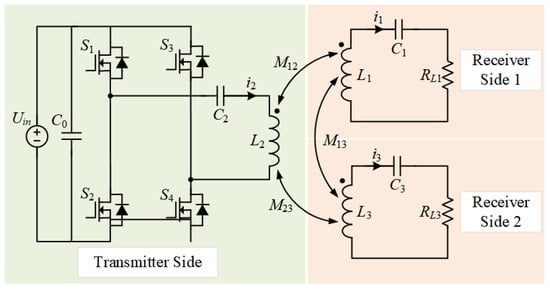
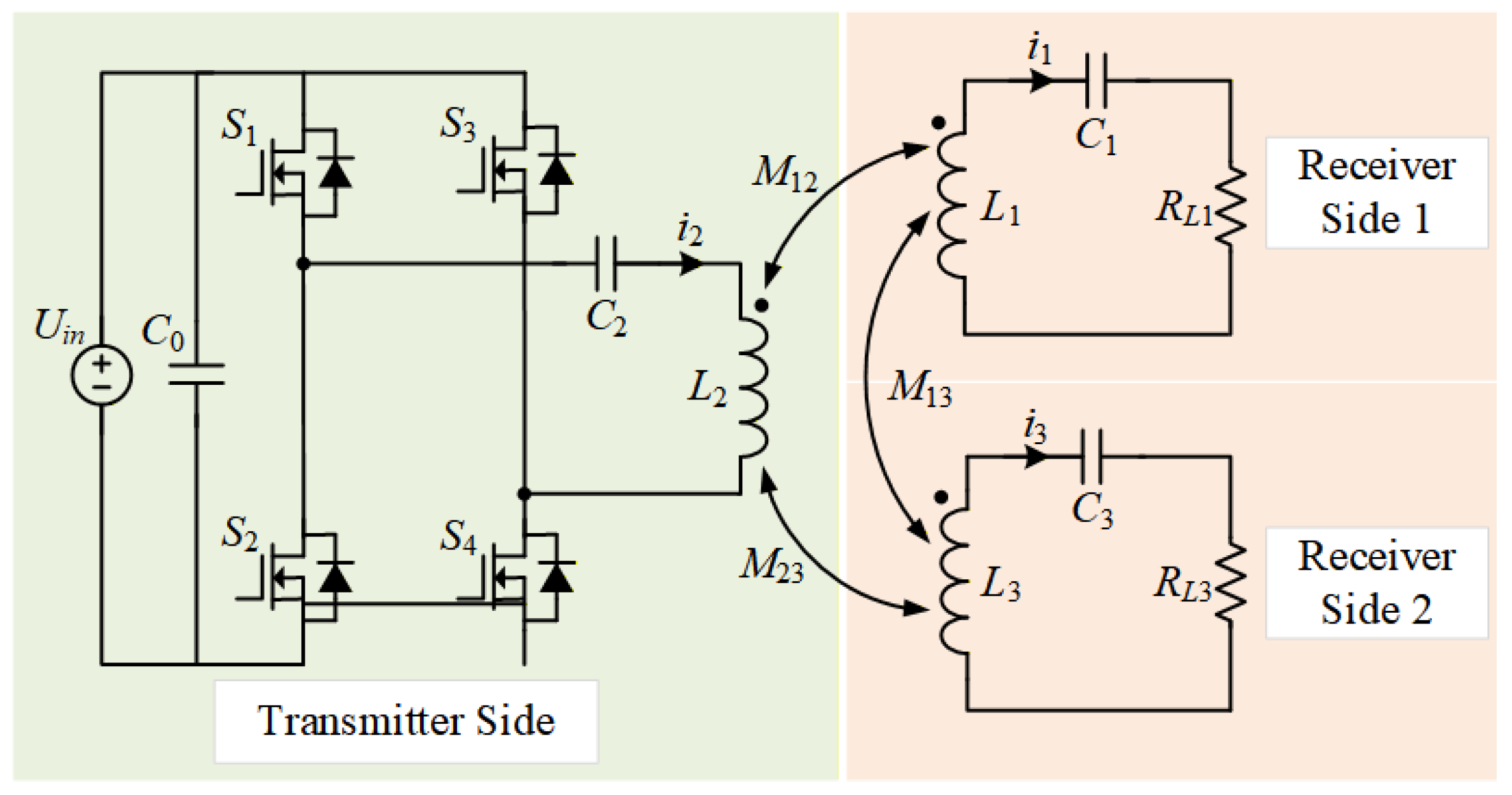
A tri-coil dual-load MCR–WPT system consists of a high-frequency power source, one transmitter coil (Tx), two receiver coils (Rx1, Rx2), and their respective loads, as shown in Figure 1. This system converts DC power into high-frequency AC power through inversion. The transmitter coil transmits electrical energy to the receiver coils via resonant coupling, thereby supplying power to the loads. All coils in this study adopt identical planar helical coil structures. Due to the strong inductive properties of planar helical coils, the addition of compensation capacitors enables coupled resonance and thus facilitates efficient energy transfer. The distance between the transmitter coil and receiver coil Rx1 is denoted as , the distance between the transmitter coil and receiver coil Rx2 is denoted as , and the distance between the two receiver coils is denoted as .
Figure 1.
Circuit diagram of the tri-coil dual-load MCR–WPT.
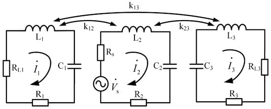
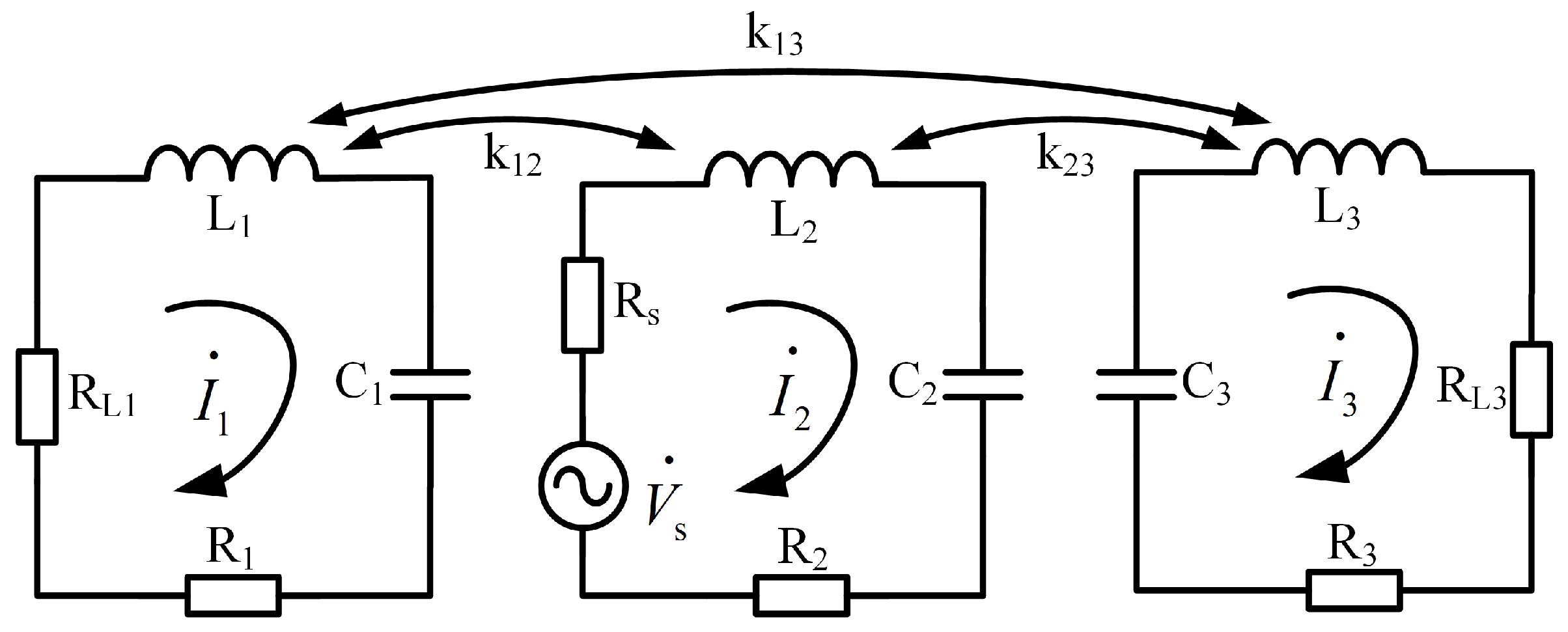
Based on the single-transmitter dual-receiver system shown in Figure 1, an equivalent circuit model of the tri-coil dual-load MCR–WPT system is established, as shown in Figure 2. The system consists of a single transmitter, dual receivers, and a dual-load simultaneous power reception structure, in which each receiver is directly connected to an independent load. and represent the two loads, while , , and denote the equivalent resistances of the receiving coil Rx1, the transmitting coil, and the receiving coil Rx2, respectively. , , and denote the inductance of the receiving coil Rx1, the transmitting coil, and the receiving coil Rx2, respectively; , , and denote the compensation capacitance of the receiving coil Rx1, the transmitting coil, and the receiving coil Rx2, respectively; , , represent the loop currents of the receiving coil Rx1, the transmitting coil, and the receiving coil Rx2, respectively; denotes the internal resistance of the power supply; , and represent the coupling coefficients between the transmitting coil and the receiving coil Rx1, between the transmitting coil and the receiving coil Rx2, and between the two receiving coils, respectively.
Figure 2.
Equivalent circuit of the tri-coil dual-load MCR–WPT.
Based on the equivalent circuit shown in Figure 2, applying Kirchhoff’s voltage law yields the impedance matrix equation for the equivalent circuit:
where , , and are the equivalent impedances of the Rx1, Tx, and Rx2 loops, respectively, which can be expressed as
When the system operates under resonant coupling, all coils are in a resonant state, i.e.,
2.2. Derivation of Load Power and Transmission Efficiency
Based on the impedance matrix established above, the loop currents of the transmitter and the two receiver branches can be obtained by solving the circuit equations. When the system operates around the resonant condition, the current expressions can be derived as
where , , and .
Consequently, the power dissipated in loads and can be expressed as
From Equation (5), the results indicate that the load power depends on the system frequency, mutual inductance, coil resistance and input voltage , and is also affected by the load connected to the parallel receiving coil circuit. According to the maximum power transfer theorem of circuit theory, under the simplified condition where the influence of the other receiving branch is neglected, the condition for maximum power delivery to load is
where denotes the impedance reflected from the transmitter side to the receiver side, with the equivalent coil resistance neglected. Similarly, when , the load receives maximum power. Therefore, when both resistive loads satisfy the maximum power condition, the total output power delivered to both loads at that frequency reaches its maximum value.
For a dual-load resonant WPT system with one single transmitter and two receivers, when mutual inductance between the two receiver coils is neglected, the dual-load system affects the transmitter circuit by increasing the reflected impedance. On the receiving side, the electrical energy delivered to the loads is mainly determined by the magnitude of the transmitter circuit current and the receiver circuit parameters. Given a fixed mutual inductance, increasing the transmitter-side current effectively enhances the electrical energy delivered to the loads.
Under the simplified condition that receiver-side cross-coupling is neglected, the input impedance of the system can be derived as
The overall transmission efficiency of the resistive dual-load system can be calculated as
From the above expression, it is clear that system efficiency is determined not only by the switching frequency and mutual inductance and between the transmitter and receiver coils, but also by the coil resistances and the loads and . Comparing Equations (5) and (8), it is evident that in a dual-load system, the load power is affected by the output voltage of the power source, while the transmission efficiency of the system remains unaffected by it.
3. Investigation of Frequency-Splitting Evolution Mechanisms
In contrast to conventional single-load MCR–WPT systems, the tri-coil dual-load system investigated in this study consists of multiple magnetic coupling channels and two independent receiving branches, as summarized in Table 1. Owing to this multi-branch coupled configuration, its frequency-splitting behavior exhibits different coupling characteristics, modal evolution mechanisms, and frequency-response patterns from those of a single-load system. Specifically, the peak-power frequencies are not determined solely by the transmitter–receiver coupling state but are jointly affected by the dominant Tx–Rx1 and Tx–Rx2 coupling paths, the receiver-side cross-coupling path, and the inter-load energy redistribution between the two receiving branches.
Table 1.
Comparison Between Single-Load and Dual-Load MCR–WPT Systems.
Due to the presence of multiple coupling paths in the system, the resonant frequencies of different modes shift to different extents, potentially resulting in output characteristics with two or even three peaks. To characterize the frequency splitting phenomenon in a tri-coil dual-load MCR–WPT system under over-coupled conditions more clearly, the typical peak patterns can be classified into three categories: the primary splitting peak, the secondary resonance peak, and the weak feature peak induced by cross-coupling. Among these, the primary splitting peak is mainly caused by strong coupling between the transmitter coil and the two receiver coils, reflecting the splitting behavior of the dominant system mode on both sides of the natural resonant frequency . The secondary resonance peak originates from local mode restructuring under the combined effect of multiple coupling paths and is typically manifested as an additional peak or shoulder. The weak feature peak is primarily caused by cross-coupling between the receiving coils, with a relatively small amplitude and a limited impact on the main energy-transfer process of the system.
3.1. Impact of Dominant Coupling Paths on Primary Splitting Peaks
In a tri-coil dual-load MCR–WPT system, the coupling paths Tx–Rx1 and Tx–Rx2 are the dominant energy-transfer channels. These two coupling paths mainly determine the locations and amplitudes of the primary splitting peaks. When the coupling between the transmitter and the receiver coils is weak, the system maintains a single resonant operating point near the designed natural resonant frequency . Under this condition, the impedance matching relationship is only slightly affected by magnetic coupling, and the maximum output power can still be obtained around . However, as the coupling coefficients and increase, the system gradually enters the over-coupled region. The original single resonant mode is then separated into multiple coupled modes, and the maximum power transfer points shift away from the designed resonant frequency. Consequently, two dominant power peaks appear on both sides of , while a power trough may occur near the original resonant frequency. This behavior indicates that the peak-power frequencies are no longer determined solely by the compensation resonant frequency of each isolated coil, but by the modal resonant frequencies of the coupled system.
When the distance between Rx1 and Rx2 is fixed, changes in the specific position of the transmitter coil simultaneously alter both and . Under the coaxial collinear arrangement, where the transmitter coil is positioned between the two receiver coils, the distances among the three coils satisfy . Therefore, both and can be expressed as functions of the distance between receiver coils Rx1 and Rx2.
To analytically characterize the variation of mutual inductance with axial separation, each planar spiral coil is represented by an equivalent circular current loop with the same effective radius and turn number. Consider the coil as the transmitting coil, with an effective radius , turn number , and excitation current . For a coaxial circular loop, the axial component of the magnetic flux density at a distance d from the center of the coil is expressed as
For the receiving coil , the magnetic field over its effective area is assumed to be approximately uniform. The effective area of one turn of the coil is expressed as
Accordingly, the magnetic flux passing through one turn of the coil can be expressed as
Since the coil has turns, the total flux linkage of the receiving coil is
According to the definition of mutual inductance , the mutual inductance between two coaxially placed planar helical coils can be approximated as
where denotes the magnetic permeability in free space; and represent the number of turns in the two coils, respectively; and denote the radii of the two coils; d indicates the distance between the coils.
Since the coil structures are identical, it is assumed that each coil has N turns and radius r. Therefore, and can be expressed as
Equations (13) and (14) indicate that the mutual inductance decreases with increasing transmission distance. Therefore, when the transmitter is close to either receiver coil, the corresponding mutual inductance becomes larger, which strengthens the transmitter–receiver coupling and makes the system more likely to enter the over-coupled state. This disrupts the original matching conditions, preventing the system from achieving maximum transmission efficiency at the resonant frequency. Instead, when the transmission distance increases, the coupling strength decreases, and the split-frequency branches gradually converge toward .
3.2. Influence of Cross-Coupling on Local Modal Reconfiguration
In addition to the dominant Tx–Rx1 and Tx–Rx2 coupling paths, the receiver-side cross-coupling path Rx1–Rx2 also influences the modal characteristics of the tri-coil dual-load system. Unlike and , which are directly responsible for the main energy transfer from the transmitter to the loads, introduces magnetic interaction between the two receiving branches.
The influence of manifests itself primarily as local modal reconfiguration and energy redistribution between Rx1 and Rx2. When is relatively weak, the overall frequency-response profile remains dominated by the transmitter–receiver coupling paths. Under this condition, the primary splitting peaks are mainly determined by and , while the cross-coupling path has limited influence on the main operating point. However, as the receiver-side cross-coupling increases, the current and magnetic-field distribution in one receiving branch can further affect the other branch, thereby introducing additional local modal components into the frequency response. These local modal interactions may appear as secondary resonance peaks, shoulder peaks, or weak characteristic peaks near the primary splitting peaks. Although such peaks generally have smaller amplitudes and do not dominate the main energy-transfer process, they can modify the local frequency-response curve and affect the power allocation between the two loads. Therefore, receiver-side cross-coupling is an important factor contributing to the asymmetric and locally multi-peak characteristics of the tri-coil dual-load MCR–WPT system.
3.3. Effect of Load Resistance on Power Amplitude
In addition to the coupling coefficients, the load resistances also influence the output characteristics of the tri-coil dual-load MCR–WPT system. However, their dominant effect is different from that of the coupling coefficients. The coupling coefficients mainly determine the modal resonant frequencies and the locations of the splitting peaks, whereas the load resistances primarily affect the damping condition, impedance matching relationship, and power amplitudes of the two receiving branches.
To obtain an explicit analytical expression for the splitting-frequency condition, the receiving coils are assumed to have identical geometrical structures and resonant parameters. Under this assumption, the system parameters satisfy
In multi-load systems, the resistances of the transmitter and receiver sides are often unequal, and the variable is introduced. The inductances and compensation capacitances at the transmitter and receiver ends can be made equal through parameter compensation methods. Typically, the secondary windings are placed in parallel at a considerable distance, resulting in negligible mutual inductance between the coils. Thus, the mutual inductance between the two receiver coils in the secondary can be neglected, i.e., . The generalized detuning factor and the generalized coupling factor are introduced, which are defined as
where Q is the coil quality factor and is the natural resonant angular frequency of the system. The generalized coupling factor is expressed as
Accordingly, the impedance of the transmitter and receiver ends can be derived, respectively, as
The total power received by the dual loads is calculated as
Taking the first derivative of the total received power P with respect to the generalized detuning factor and setting it to zero yields
From Equation (21), it can be seen that when , the system operates in the under-coupled state, where the received power reaches its maximum only at the natural frequency (), and no frequency splitting occurs. When , the system operates in a critically coupled state, where the received power again reaches its maximum only at the natural frequency (), and no frequency splitting occurs. When , the system operates in an over-coupled state. Equation (21) yields three solutions: , , and , resulting in frequency splitting. It can be easily verified that the received power of the system reaches its maximum at , indicating that the system is in an over-coupled state.
When the system operates in the over-coupled state, the frequency splitting phenomenon occurs. By substituting Equations (16) and (17) into (21), the following expression can be obtained:
Therefore, the split angular frequencies can be expressed as
where
Equations (21)–(23) reveal the relationship among coupling strength, load-related damping, and split-frequency locations. An increase in mutual inductance M increases the generalized coupling factor , making the system more likely to enter the over-coupled region and resulting in greater separation between the split-frequency peaks. In contrast, the load resistance affects the equivalent resistance R and the resistance ratio , thereby modifying the damping condition and the power amplitude.
4. Simulation and Experimental Verification
4.1. Simulation Analysis of Splitting Trajectories
In order to verify the theoretical analysis of the frequency-splitting characteristics of the tri-coil dual-load MCR–WPT system, parametric simulations were carried out using PSIM Professional 2025 (Version 2025.0.0.3987). A fixed-step transient simulation was adopted, with the simulation time step set to 0.1 μs. For each driving-frequency point, the circuit was simulated until the transient response reached steady-state, and the load power was calculated from the corresponding steady state voltage and current waveforms. Considering that the nominal resonant frequency of the tri-coil system is approximately , the selected time step provides sufficient temporal resolution to capture the resonant current, voltage, and output-power variations during the frequency sweep. The key simulation parameters are summarized in Table 2.
Table 2.
System Simulation Parameters.
In the PSIM model, the losses of the main circuit were represented by equivalent lumped resistances, including coil winding resistances, internal resistance of the power source, and load resistances. These resistive parameters were included in the equivalent circuit and the corresponding simulation model. This simplification was adopted because the main purpose of the simulation is to reveal the frequency-splitting trajectory and peak-frequency migration caused by modal coupling, rather than to accurately predict the detailed loss distribution of each component. Within the investigated frequency range, these frequency-dependent losses mainly affect the output-power amplitude, while their influence on the qualitative trend of the split-frequency locations is relatively limited.
To clarify the parameter settings and analytical objectives of different simulation scenarios, the simulation cases considered in this study are summarized in Table 3, whose classification helps distinguish the overall response of the system from the subsystem level and the cross-coupling analysis. Specifically, Case 1 is used to evaluate the overall frequency-response characteristics of the tri-coil dual-load MCR–WPT system. Cases 2 and 3 are introduced to separately investigate the frequency splitting behavior of the Tx–Rx1 and Tx–Rx2 subsystems by neglecting the influence of the other receiving branch. Case 4 further takes into account the receiver-side cross-coupling between Rx1 and Rx2, aiming to reveal its influence on modal redistribution and secondary power peaks.
Table 3.
Summary of simulation cases for frequency-splitting analysis.
Figure 3 presents the frequency response of the system. It can be clearly observed that the output power exhibits a typical double-peak characteristic as the frequency varies, with the two power maxima located on either side of the designed resonant frequency. This phenomenon indicates that the system operates in the over-coupled region, where the imaginary part of the equivalent impedance is no longer zero at the resonant frequency, thereby leading to resonance splitting. Under this condition, the strong coupling between the transmitting and receiving coils destroys the original impedance-matching condition, causing the power peaks to shift away from the designed resonant frequency and consequently resulting in a significant reduction in power transfer efficiency.
Figure 3.
Load-power frequency responses of the tri-coil dual-load MCR–WPT system.
4.1.1. Frequency-Splitting Characteristics of the Tx–Rx1 Subsystem
For the two-coil system consisting of a transmit coil and a single-sided receive coil Rx1, neglecting the coupling effect generated by the receive coil Rx2, the primary causes of frequency splitting in the system are the coupling coefficient and the mismatch between the load resistance and the equivalent impedance. To further validate and analyze the specific effects of the coupling coefficient and the load impedance on frequency splitting and transmission performance in conjunction with the transmission performance expressions, the simulation parameters are set as follows: μH, , and the designed resonant frequency is .
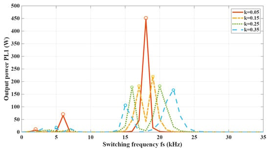
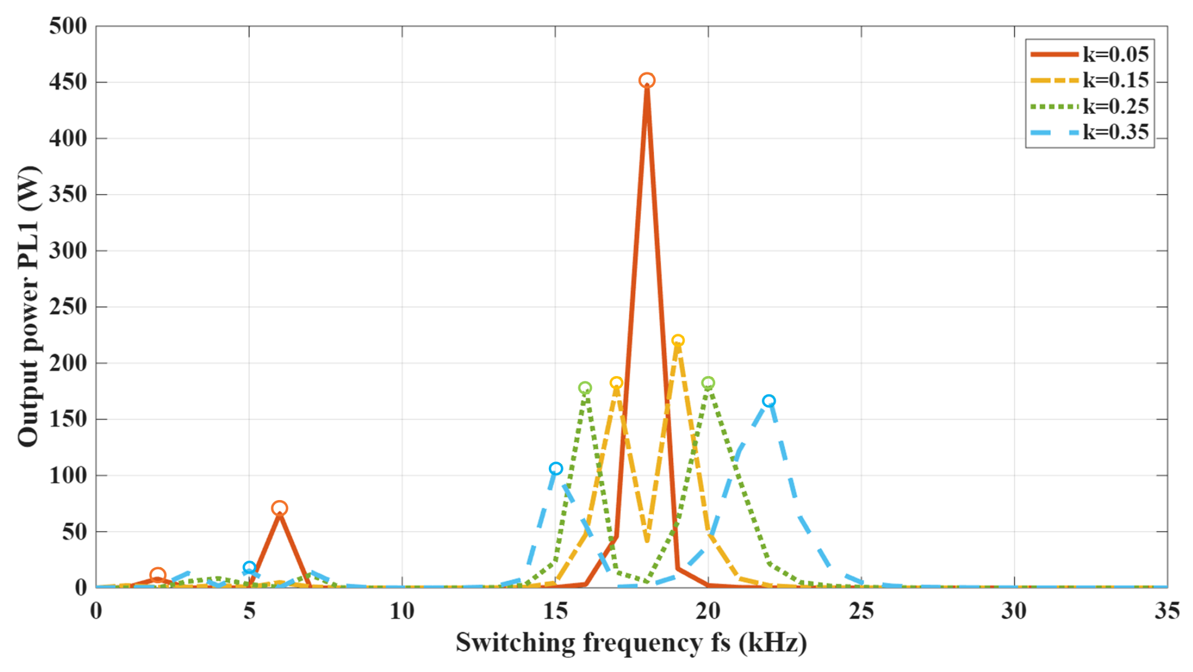
Figure 4 shows the relationship between transmission performance and frequency variation as the coupling coefficient k between the system coils increases from to while the load impedance remains constant. The results indicate that when , the system achieves a maximum output power of approximately at the resonant frequency of . However, as the coupling coefficient increases, frequency splitting occurs with two or three distinct peaks. When , the maximum output power occurs at , followed by , while the output power at the resonant frequency of decreases to its minimum value.
Figure 4.
Output power versus driving frequency of the Tx–Rx1 subsystem under different coupling coefficients ().
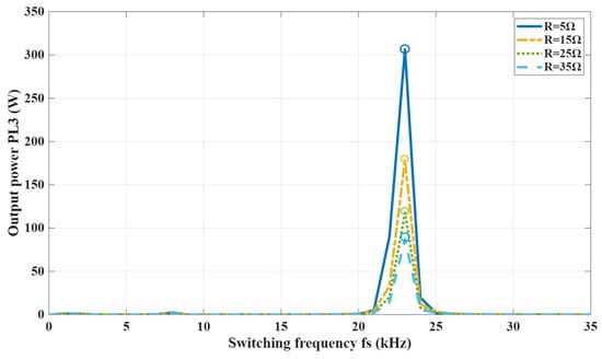
Figure 5 shows the relationship between transmission performance and frequency variation when the load resistance changes from to while the coupling coefficient remains constant. The results indicate that as the load resistance gradually increases, the system does not exhibit frequency splitting. The maximum output power remains centered on the resonant frequency. Furthermore, the maximum output power decreases as the load resistance increases, while the maximum frequency remains nearly unchanged. This indicates that the effect of changes in load resistance on the frequency-splitting phenomenon is far less significant than that of the coupling coefficient.
Figure 5.
Output power versus driving frequency of the Tx–Rx1 subsystem under different load resistances ().
4.1.2. Frequency-Splitting Characteristics of the Tx–Rx2 Subsystem
For the dual-coil system consisting of the transmitting coil and the receiving coil Rx2, with the influence of the receiving coil Rx1 neglected, the frequency splitting phenomenon observed in the system is also attributable to the coupling coefficient and the load impedance mismatch. The simulation parameters are set as follows: μH, , and the designed resonant frequency is .
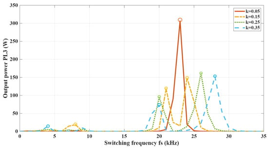
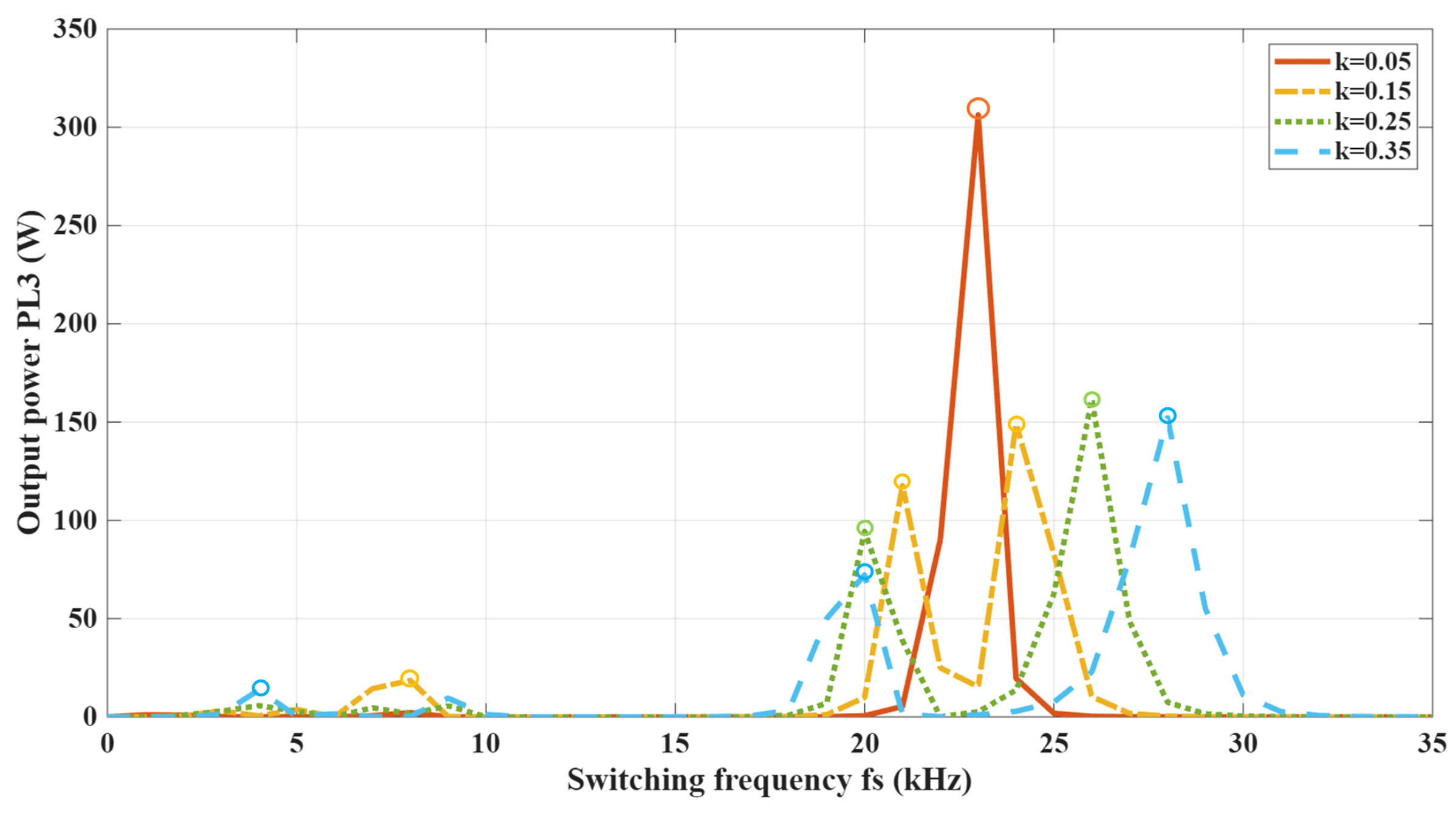
Figure 6 shows the variation in transmission power with frequency when the coupling coefficient increases from to while the load impedance remains constant. It can be observed that at a coupling coefficient , the system achieves a maximum transmission power of at the resonant frequency . As the coupling coefficient k increases, the frequency splitting phenomenon occurs, and the transmission power curve generates two or three splitting peaks. When , power peaks appear in and successively, while the transmission power at the designed resonant frequency drops to the minimum value.
Figure 6.
Output power versus driving frequency of the Tx–Rx2 subsystem under different coupling coefficients ().
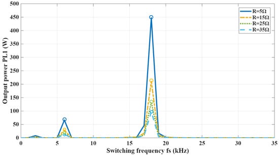
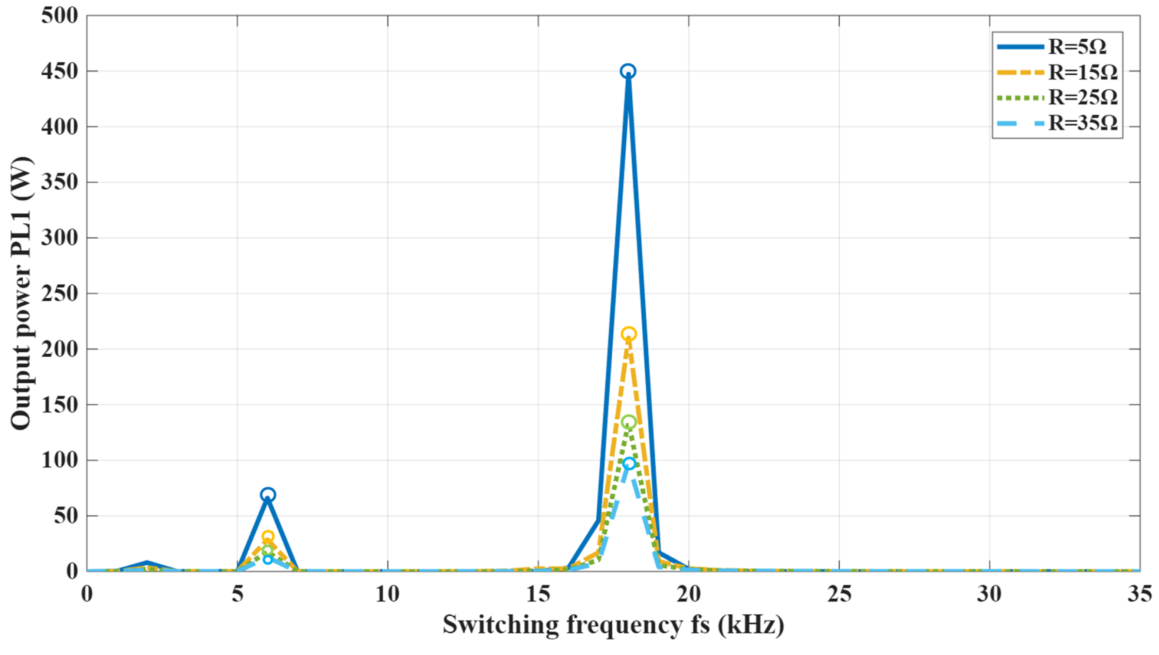
Figure 7 shows the relationship between transmission power and frequency for the system as the load resistance varies from to while the coupling coefficient remains constant. The results indicate that as the load resistance gradually increases, the system does not exhibit frequency splitting. The maximum output power remains centered on the resonant frequency of . Furthermore, the simulation results indicate that within the load range under consideration, the load resistance has a relatively weak influence on the frequency splitting characteristics, whereas the system coupling coefficient exerts a more significant and dominant influence on the frequency splitting behavior.
Figure 7.
Output power versus driving frequency of the Tx–Rx2 subsystem under different load resistances ().
4.1.3. Cross-Coupling Effects Between Rx1 and Rx2
For the tri-coil dual-load system, with mutual coupling between the two receiving coils taken into account, a simulation analysis of the two load powers is carried out. The simulation parameters are set as follows: , μH. Simulations are conducted by varying the coupling coefficients between the two receiving coils while keeping the coupling coefficients for the third coil constant.
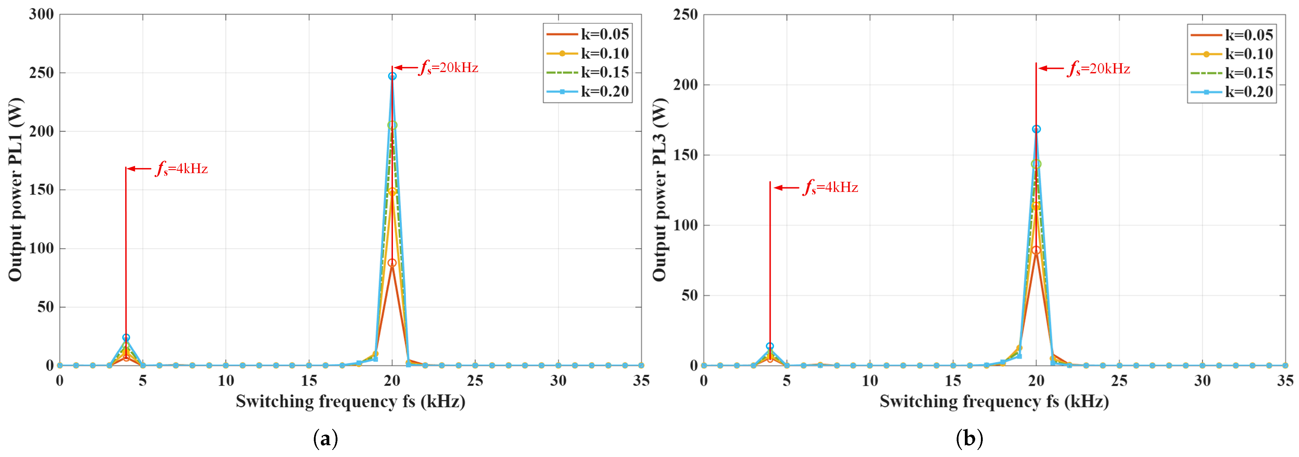
Figure 8 shows the curves of the two load powers as a function of drive frequency when the cross-coupling coefficient increases from to and the coupling coefficient between the transmitting and receiving coils remains constant. When the system is near resonance, both output powers exhibit a single distinct peak, and this peak increases significantly as the coupling coefficient k increases. This indicates that despite cross-coupling in the tri-coil structure, the system maintains excellent resonant characteristics without noticeable multi-peak frequency splitting or power distortion. The cross-coupling between receiving coils does not disrupt the primary coupling path, allowing the system to remain dominated by transmitter-receiver coupling. Further observation reveals that as the coupling coefficient k increases, the peak values of and gradually increase from approximately and to approximately and , respectively. This result indicates that stronger receiver-side cross-coupling enhances the magnetic interaction between the two receiving branches and modifies the energy redistribution between the two loads, thereby strengthening the primary coupling link.
Figure 8.
Load-power frequency responses of the tri-coil dual-load MCR–WPT system under different receiver-side cross-coupling coefficients. (a) Output power response of . (b) Output power response of .
More significantly, the differing magnitudes of increase in the two outputs maintain a constant proportional relationship. This indicates that cross-coupling between the receiving coils induces an energy redistribution effect between the two loads: when the resonant current in one load increases, the other load receives additional magnetic excitation through cross-coupling, thereby gaining extra power. This mutual influence causes the power in both loads to exhibit synchronous enhancement characteristics as the coupling coefficient varies. Moreover, a set of smaller secondary peaks can be observed in the lower frequency range. These sub-peaks persist under varying coupling conditions and exhibit slight amplification with increasing coupling coefficients, though their amplitudes remain significantly smaller than the main peak. This phenomenon indicates that cross-coupling at the receiving end introduces weaker coupling modes, creating additional sub-resonance points in the low-frequency range. However, these modes do not dominate the overall frequency response of the system, so they will not cause significant interference to the operating point of the system.
To distinguish the different peak components in the frequency response, the typical peak patterns of the tri-coil dual-load system can be classified as shown in Table 4.
Table 4.
Typical Peaks in Tri-Coil Dual-Load MCR–WPT.
The classification in Table 4 shows that the frequency response of the tri-coil dual-load system is shaped by both the dominant transmitter–receiver coupling paths and the receiver-side cross-coupling path. Therefore, the multi-peak response observed in the tri-coil system should be regarded as the result of modal splitting, modal competition, and local energy redistribution, rather than a simple extension of the two-coil bimodal splitting phenomenon.
4.2. Experimental Setup and Performance Validation
In order to verify the proposed frequency-splitting mechanism in a progressive manner, the experimental validation is organized into two stages. First, a two-coil single-load MCR–WPT system is used as a benchmark to verify the basic frequency-splitting behavior under different coupling conditions. Second, a tri-coil dual-load MCR–WPT system with receiver-side cross-coupling is investigated to further verify the frequency-splitting evolution under multiple coupling paths.
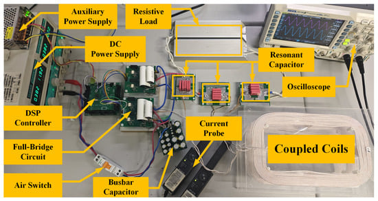
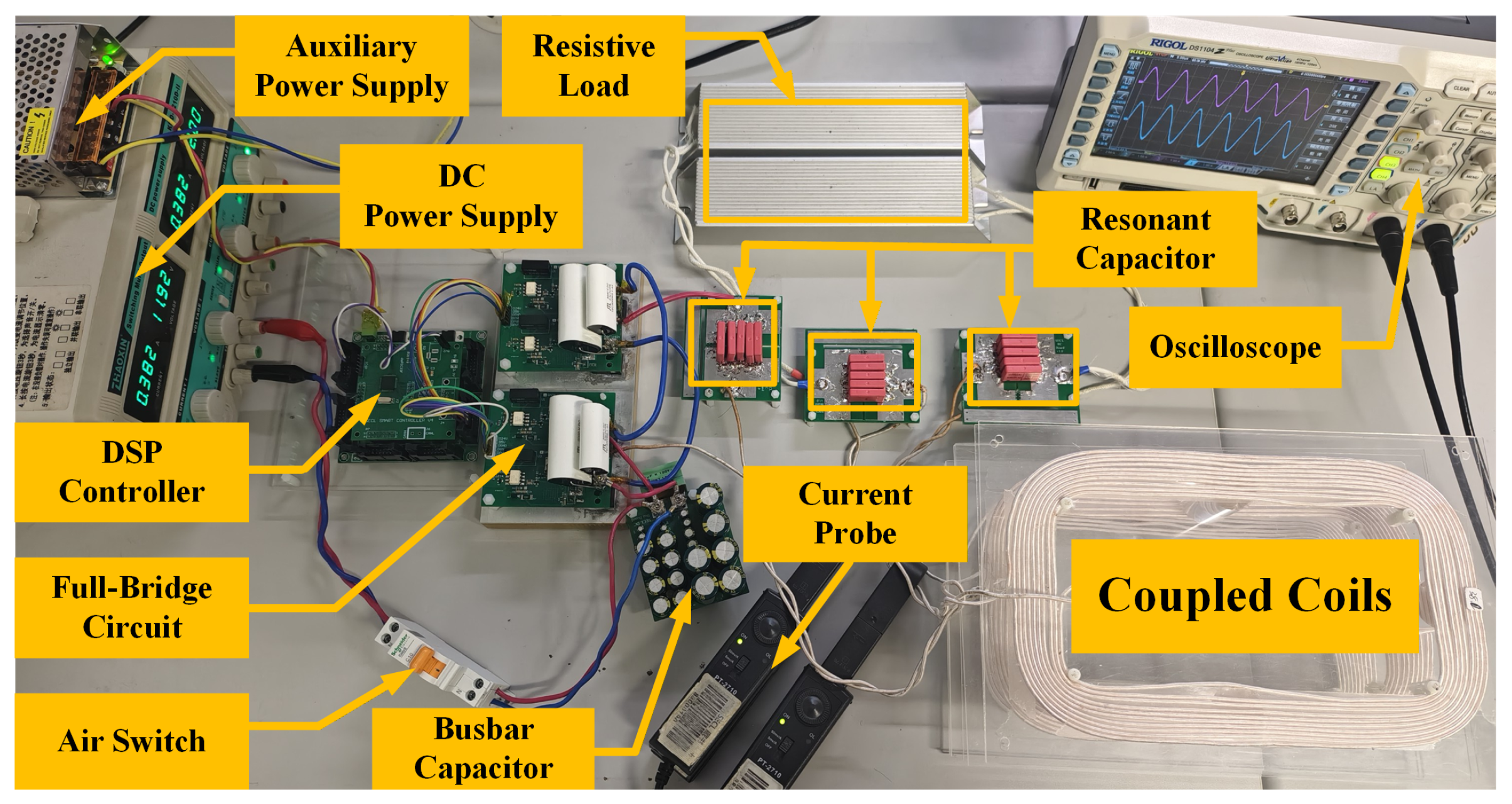
An experimental platform is constructed to validate the theoretical analysis, as shown in Figure 9. The experimental system consists of a DC power supply, a DSP controller, a full-bridge inverter, one transmitter coil, two receiver coils, and two independent resistive loads. The transmitter and receiver coils are implemented as planar helical coils and are arranged in a coaxial parallel configuration. The DC input voltage is set to , the loads are implemented using pure resistors, and the operating resonant frequency is set to . The key system parameters are summarized in Table 5.
Figure 9.
Experimental platform of the WPT system.
Table 5.
System Experimental Parameters.
The compensation capacitance was selected according to the basic resonant condition of each compensated coil loop. For each coil, based on the resonant-frequency relationship , the required compensation capacitance can be calculated as
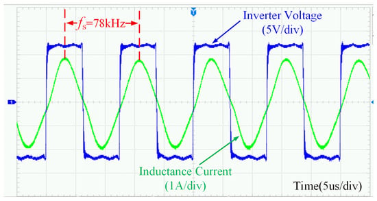
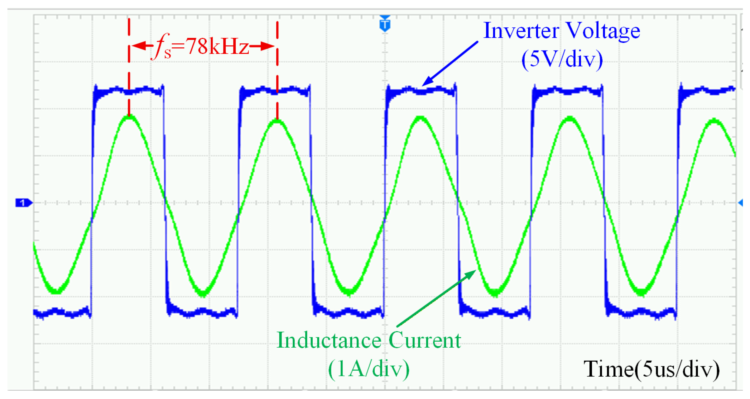
As shown in Figure 10, the voltage and current waveforms on the primary-side are measured when the system operates at the resonant frequency of . The primary voltage presents a high-frequency square-wave waveform generated by the inverter, while the primary current exhibits an approximately sinusoidal waveform under the resonant condition. The primary side voltage and current are nearly in phase, indicating that the experimental system maintains a stable resonant operating state.
Figure 10.
Measured primary-side voltage and current waveforms under stable resonant operation.
4.2.1. Two-Coil Single-Load Validation Experiment
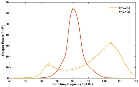
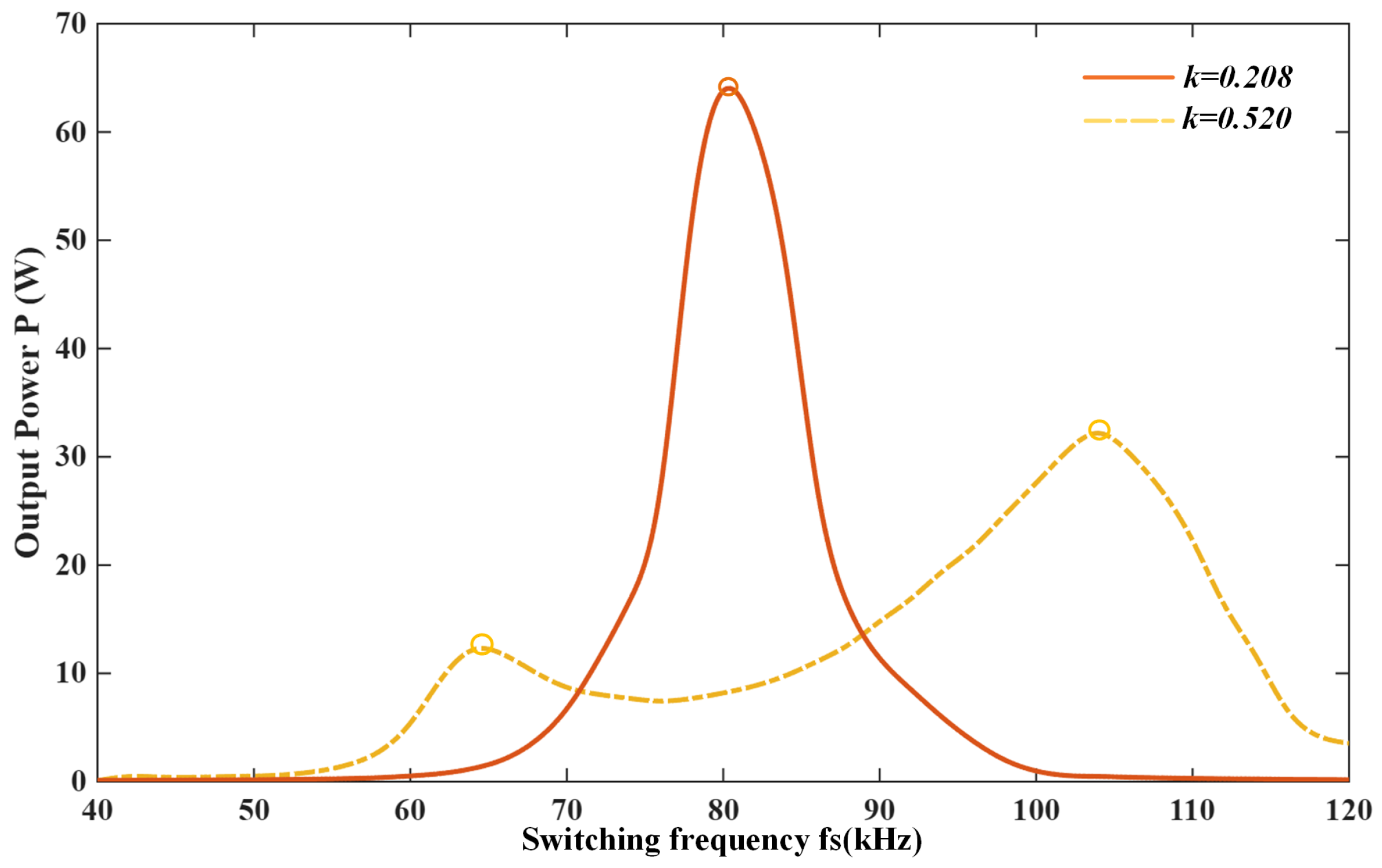
The transmitting and receiving coils were maintained in a coaxial parallel arrangement throughout the experiment. The measured transmitted-power curves as functions of the driving frequency at transmission distances of and are shown in Figure 11. The corresponding coupling coefficients, obtained from the measured coil parameters, are and , respectively.
Figure 11.
Measured transfer power versus the driving frequency under different coupling conditions.
When the coupling coefficient is relatively small, as shown in Figure 11, the transmitted power exhibits only a single peak at a driving frequency of , which is close to the designed resonant frequency of . This indicates that the system operates in a single-resonance state, in which the natural resonant frequency is approximately consistent with the designed resonant frequency. Under this condition, the system operates near the resonant frequency, and the transmitted power reaches its maximum value.
When , applying Equation (21) reveals that the system has two distinct natural frequencies, namely and . As shown in Figure 11, the transmitted power exhibits frequency splitting under this condition, and the driving frequencies corresponding to the peak power points are and , respectively, both of which are close to the two natural frequency points. At the same time, it can also be observed that the transmitted power at the system’s original natural resonant frequency becomes lower.
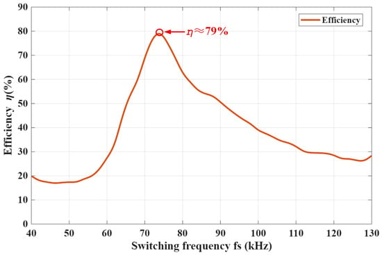
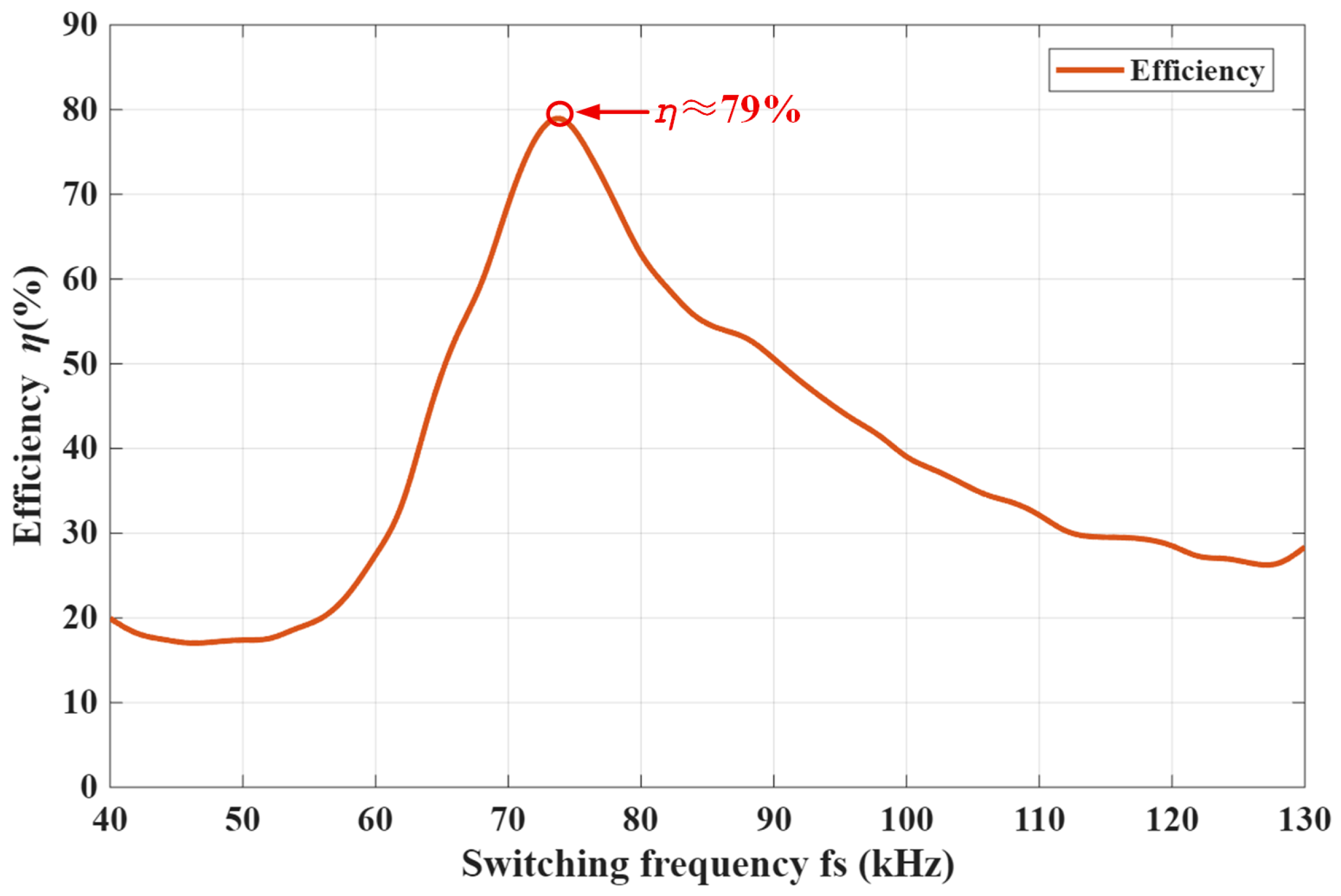
As shown in Figure 12, the transmission efficiency of the two-coil single-load MCR–WPT system exhibits a typical single-dominant-peak frequency response. As the switching frequency increases, the efficiency of the system gradually improves and reaches a maximum value of approximately 79% near the primary resonant frequency. This operating point corresponds to a relatively favorable impedance-matching condition, under which the magnetic-coupling-based energy transfer between the transmitter and receiver is most effectively achieved. When the switching frequency is further increased, the transmission efficiency decreases significantly, indicating that the system progressively deviates from the optimal operating frequency. Under this condition, the matching between the equivalent input impedance and the reflected load impedance is weakened, leading to a reduction in the proportion of effective output power relative to the input power. Therefore, this result indicates that the high-efficiency operating region of the two-coil single-load system is mainly concentrated around the primary resonant frequency, and its efficiency response is relatively simple, being primarily governed by the transmitter–receiver coupling condition and the impedance-matching characteristics.
Figure 12.
Transmission-efficiency frequency response of the two-coil single-load MCR–WPT system.
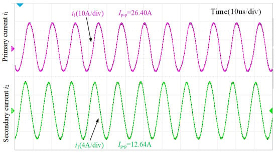
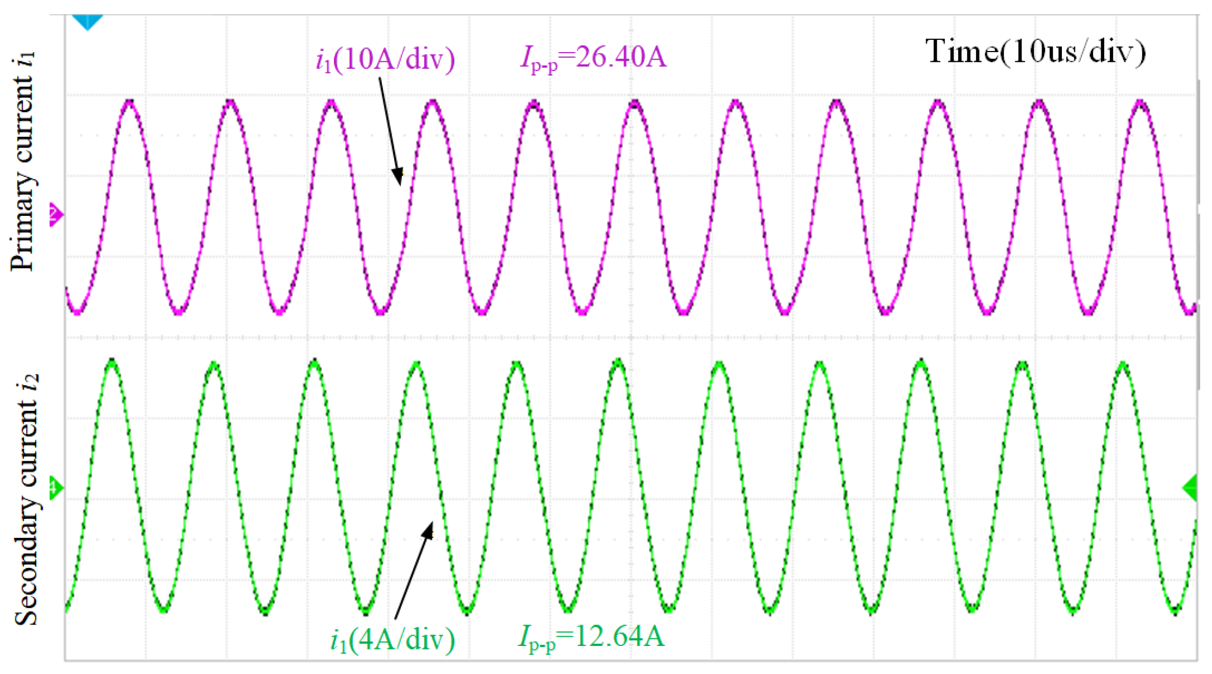
Figure 13 shows the current waveforms under system resonance conditions () when the coupling coefficient is small (). When the natural frequencies of the two circuits in the system are equal and the coupling coefficient is small, the currents in the primary and secondary loops differ by approximately in the resonant state. At this point, the impedance of both loops is purely resistive, and the input impedance of the entire system is also purely resistive, which is consistent with the results of the theoretical analysis.
Figure 13.
Current waveform under system resonance conditions ().
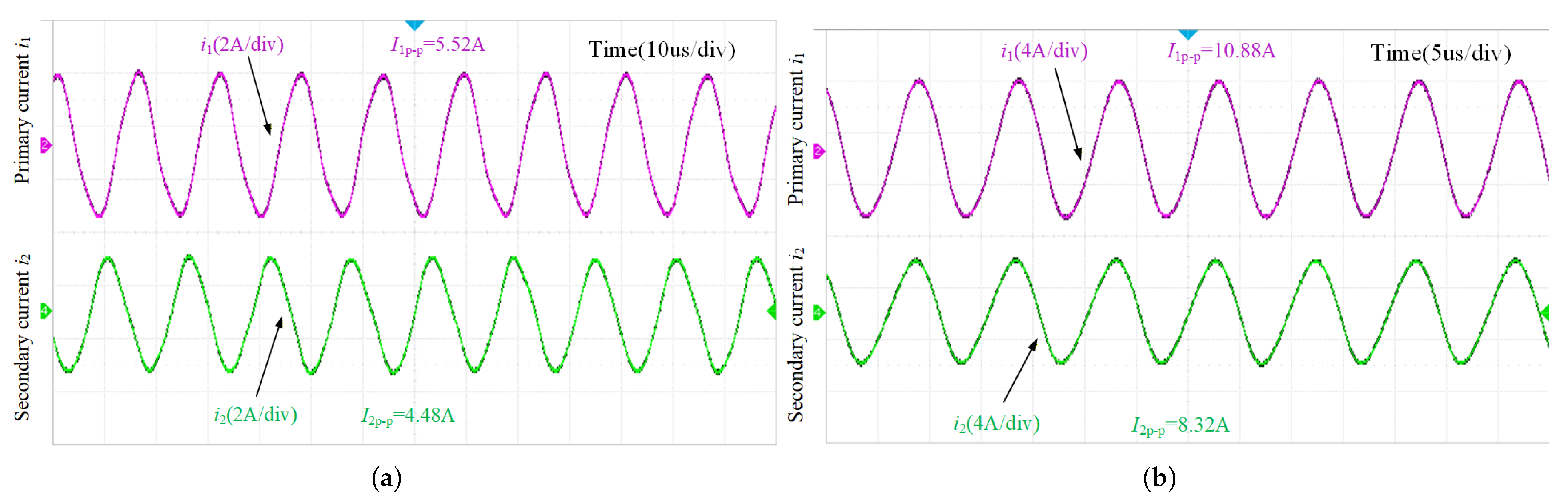
Figure 14 shows the current waveforms of the system in the resonant state when the coupling coefficient . Figure 14a shows the current waveform at , while Figure 14b shows the current waveform at . As can be seen from the figure, the current phases in the two resonance states are in-phase and out-of-phase, respectively. At these two splitting resonant frequencies, the impedance of the two loops and the input impedance are no longer purely resistive.
Figure 14.
Current waveform under system resonance conditions (). (a) The first natural frequency of the system (). (b) The second natural frequency of the system ().
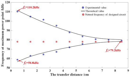
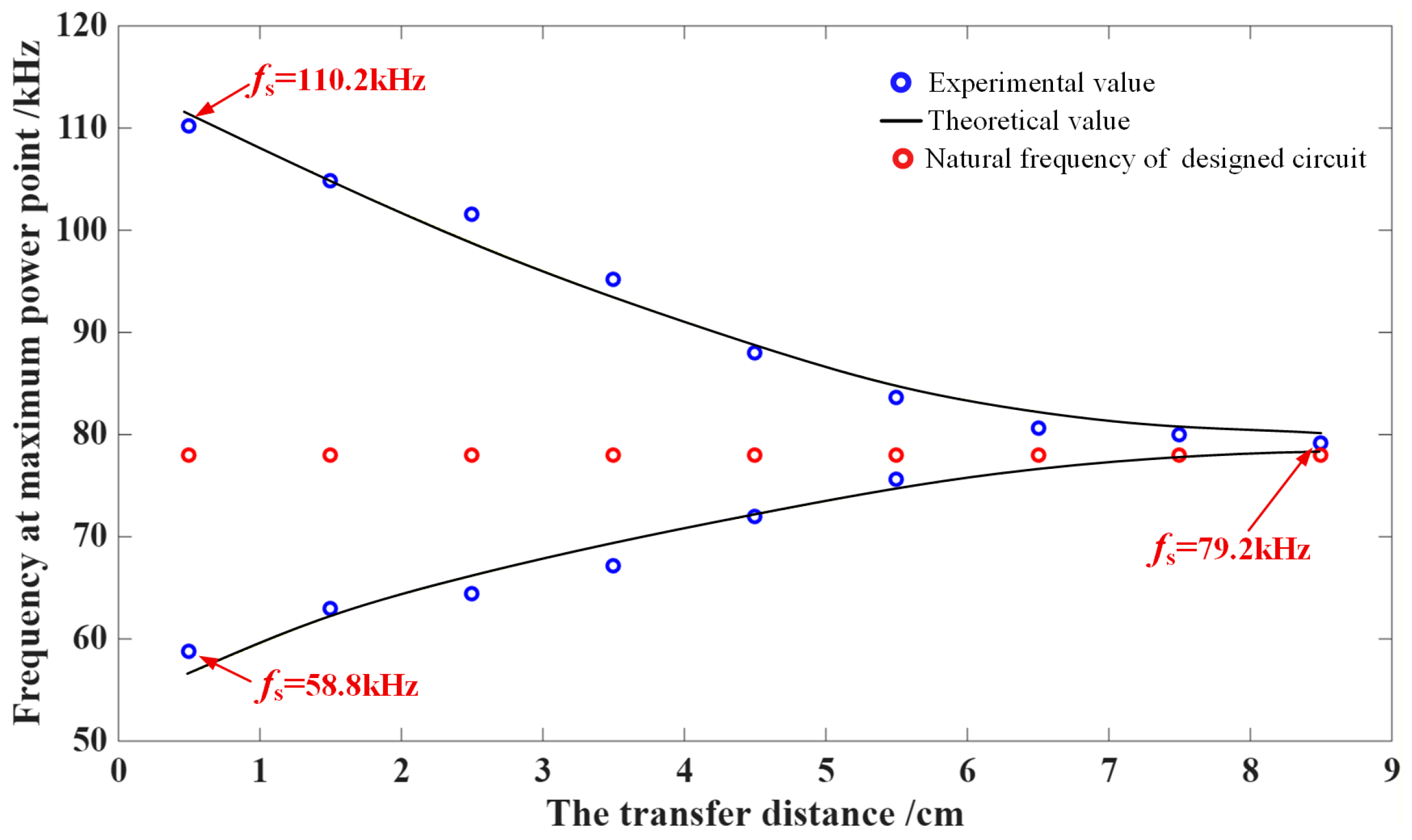
To more clearly analyze the effect of the coupling coefficient on the frequency corresponding to the maximum power transfer point, the figure shows the variation curve of the maximum power transfer point frequency as a function of the coupling coefficient (or transmission distance).
As shown in Figure 15, the peak-power frequency coincides with the designed natural resonant frequency only when the coupling coefficient is relatively small, i.e., at a relatively long transmission distance. As the coupling coefficient increases, i.e., as the transmission distance decreases, the system enters the frequency-splitting region, where two peak-power points appear, and both deviate significantly from the designed natural resonant frequency. In both the weakly coupled and strongly coupled cases, the measured peak-power frequencies are in close agreement with the natural resonant frequencies calculated in this paper. This further confirms that the current response reaches resonance, and the transmitted power attains its maximum value only when the driving frequency is equal to the system’s natural resonant frequency.
Figure 15.
Peak-power frequencies versus transmission distance in a two-coil single-load MCR–WPT system.
4.2.2. Tri-Coil Dual-Load Validation Experiment
To further verify the frequency-splitting behavior of the proposed tri-coil dual-load MCR–WPT system, the output-power frequency responses of the two loads are measured under asymmetric coupling and loading conditions.
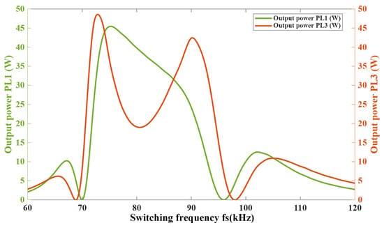
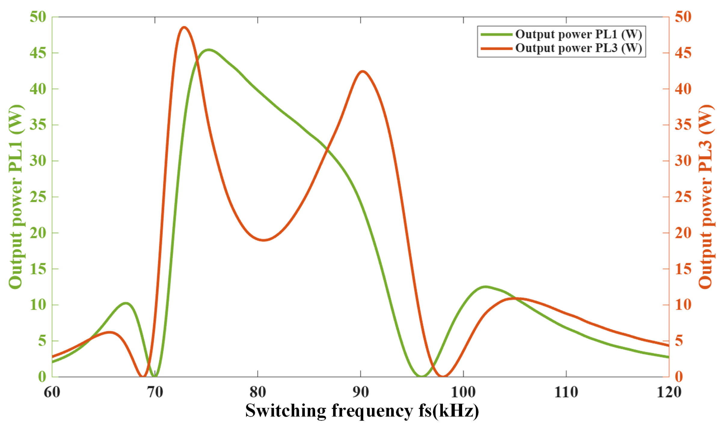
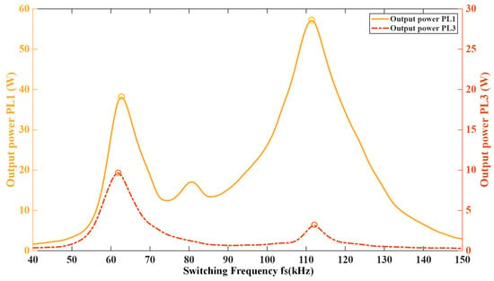
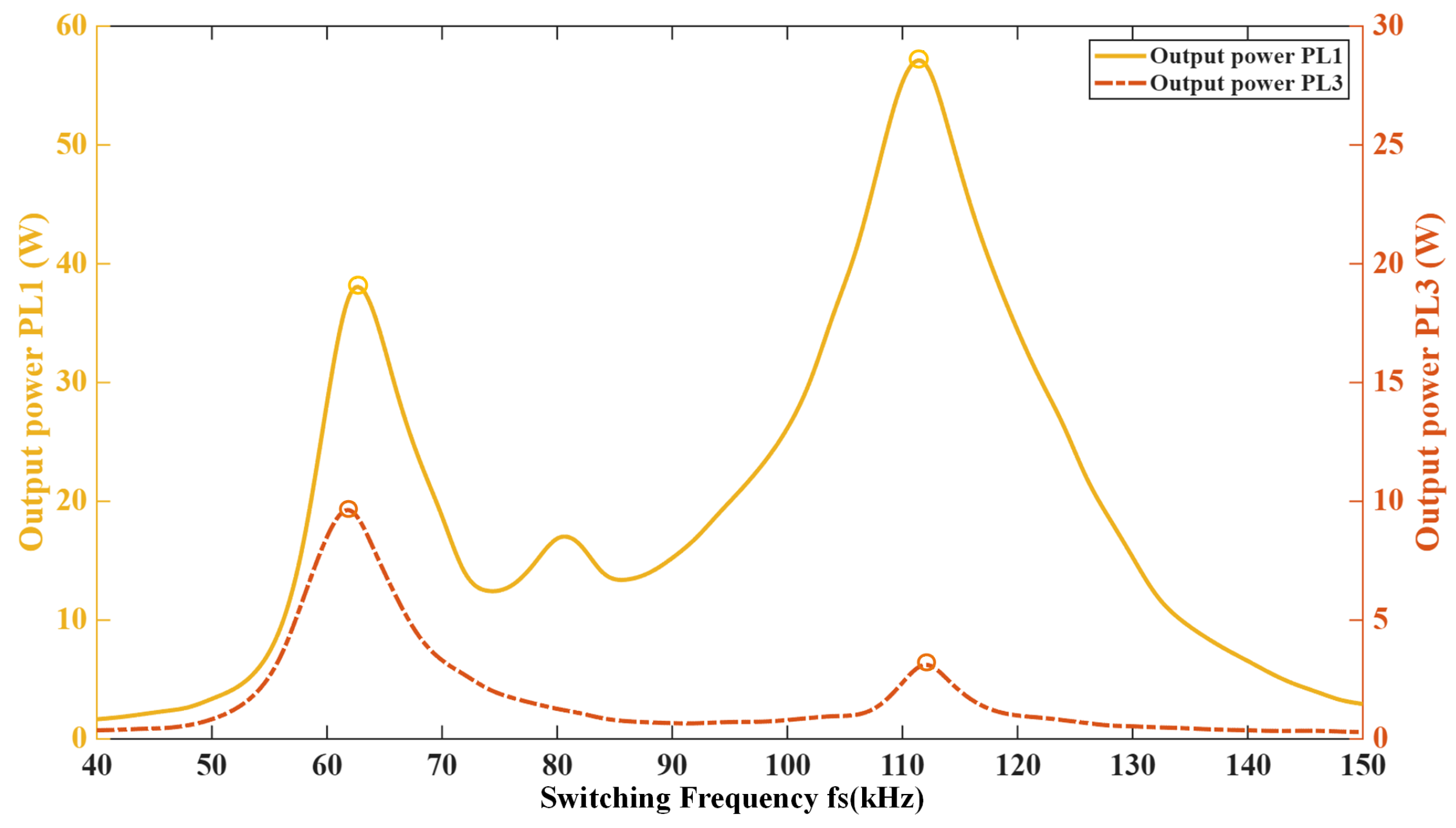
As shown in Figure 16, under the conditions of , , , and , the output–power response of an MCR–WPT system with a tri-coil dual-load configuration no longer exhibits the single-peak resonance characteristic typical of a conventional two-coil single-load system. Instead, it shows pronounced double-peak and even local multi-peak features as the driving frequency varies. Specifically, the load power presents two distinct peaks around 63 and , respectively, with the higher-frequency peak being more dominant, while the output power decreases significantly near the designed resonant frequency located between the two peaks. The load power also exhibits corresponding peak responses in a similar frequency range, but with relatively smaller amplitudes. These results indicate that the system has entered the over-coupled region in which the original single resonant mode splits under the combined action of multiple coupling paths.
Figure 16.
Load-power frequency responses of the tri-coil dual-load MCR–WPT system under asymmetric coupling conditions.
The fundamental reason is that the tri-coil dual-load MCR–WPT system contains multiple coupling channels simultaneously, namely, Tx–Rx1, Tx–Rx2, and Rx1–Rx2. The dominant coupling paths mainly determine the locations and amplitudes of the principal split peaks, whereas the cross-coupling between the two receiver coils further induces local modal reconfiguration and energy redistribution, thereby giving rise to shoulder peaks, additional peaks, or weak characteristic peaks in the vicinity of the main peaks. As the coupling strength increases, the equivalent impedance characteristics of the system are altered, and the designed resonant frequency no longer satisfies the optimal impedance-matching condition. Consequently, the maximum-power points shift from the original resonant frequency to the new natural resonant frequencies, causing the frequency response of the system to evolve from a single-peak profile into a double-peak or multi-peak profile.
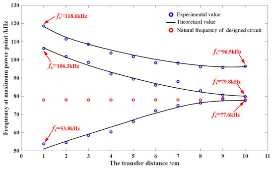
As shown in Figure 17, the frequencies corresponding to the maximum-power points in the tri-coil system exhibit a distinct three-branch evolution with transmission distance. In contrast to the two-coil system, which shows only two principal split branches, as illustrated in Figure 15, the tri-coil dual-load system develops additional modal branches under short-distance and strong-coupling conditions, indicating the formation of a multi-mode coupling state induced by multi-path magnetic coupling. As the transmission distance increases, the three frequency branches gradually converge toward the designed resonant frequency of , suggesting that the frequency-splitting effect is progressively weakened as the coupling strength decreases. The asymmetric distribution of these three branches further indicates that the frequency splitting in this system is not a simple symmetric bimodal splitting but rather an asymmetric multi-modal splitting phenomenon resulting from the combined effects of the coupling paths Tx–Rx1, Tx–Rx2, and Rx1–Rx2. In essence, the maximum-power transfer points are jointly determined by multiple modal resonant frequencies.
Figure 17.
Peak-power frequencies versus transmission distance in a tri-coil dual-load MCR–WPT system.
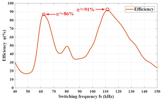
As shown in Figure 18, the transmission efficiency of the tri-coil dual-load MCR–WPT system presents a pronounced non-single-peak characteristic over the investigated switching-frequency range. Unlike the weak-coupling condition, in which the efficiency maximum is typically located near the designed resonant frequency, the measured efficiency curve exhibits two dominant peaks at approximately 62 kHz and 111 kHz. The high-frequency peak reaches approximately 91–92%, while the low-frequency peak is approximately 86%. In contrast, the efficiency is significantly reduced near the designed resonant frequency and in the intermediate frequency region, indicating that the optimal efficiency point no longer coincides with the original compensated resonant frequency. Moreover, because receiver-side cross-coupling redistributes energy between the two load branches, the load power of different receivers and their contributions to the overall efficiency may not vary synchronously. This behavior can be explained by the strong-coupling-induced variation in the equivalent input impedance and the reflected impedance. When the system enters the over-coupled region, the impedance-matching condition at the designed resonant frequency is disrupted, causing the efficiency peaks to shift toward the inherent modal frequencies of the coupled system.
Figure 18.
Transmission-efficiency frequency response of the tri-coil dual-load MCR–WPT system.
A direct comparison between the simulation and experimental results shows good qualitative agreement in terms of frequency-splitting behavior, peak-frequency evolution, and local multi-peak characteristics. As shown in Figure 16 and Figure 17, both results indicate that, when the system enters the over-coupled region, the load-power response evolves from a single-peak profile into a double-peak or locally multi-peak profile, and the maximum-power points shift away from the designed resonant frequency. Meanwhile, the measured peak-power frequencies exhibit a convergence tendency toward the designed resonant frequency as the transmission distance increases, which is consistent with the simulated splitting-trajectory evolution. The main discrepancies between the simulation and experimental results are reflected in the output–power amplitude and slight peak–frequency deviations. The lower measured output power is mainly attributed to the lower input voltage used in the experimental prototype, namely , compared with in the simulation, as well as practical non-ideal factors such as coil winding resistance, capacitor equivalent series resistance, MOSFET conduction and switching losses, and measurement losses. The slight deviations in peak-frequency locations are mainly caused by tolerances in actual inductance and capacitance values, coil-alignment errors, and variations in coupling conditions. Nevertheless, the experimentally observed asymmetric split peaks and local multi-peak characteristics are consistent with the simulation results, thereby validating the proposed frequency-splitting evolution mechanism.
Therefore, the frequency-splitting phenomenon in the tri-coil system can be essentially attributed to modal splitting and competition under the combined action of multiple coupling paths. Its direct consequences include the shift of power peak locations, the deterioration of power-transfer capability at the designed resonant frequency, and the shrinkage of the stable and efficient operating region. These results further deepen the understanding of the formation mechanism and evolution characteristics of frequency splitting in tri-coil systems and provide a theoretical basis for the subsequent suppression of frequency splitting in tri-coil dual-load systems.
5. Conclusions
This paper investigated the frequency-splitting evolution mechanism of a single-transmitter dual-receiver tri-coil dual-load MCR–WPT system considering receiver-side cross-coupling. An equivalent circuit model was developed, and analytical expressions for input impedance, load power, and transmission efficiency were derived with respect to coupling coefficients and load parameters. The main conclusions are summarized as follows:
- (1)
- The proposed multi-path magnetic-coupling model reveals the effects of the dominant Tx–Rx coupling paths, receiver–side cross-coupling, and load parameters on the load-power response. Compared with conventional two-coil systems, the coexistence of multiple magnetic coupling paths in the tri-coil dual-load system leads to more complex impedance characteristics and power distribution behavior, providing an analytical basis for extending frequency-splitting analysis to multi-coil and multi-load MCR–WPT systems.
- (2)
- Multi-path magnetic coupling is responsible for the asymmetric and locally multi-peak frequency response. Under symmetric coupling conditions, the split-frequency response is mainly governed by the Tx–Rx coupling paths; under asymmetric mutual-inductance conditions, Rx1–Rx2 cross-coupling further induces energy redistribution and local modal reconfiguration. Consequently, secondary resonance peaks, shoulder peaks, and weak characteristic peaks may appear in the frequency response, indicating distinct multi-modal coupling characteristics.
- (3)
- The coupling coefficients mainly govern the split-frequency trajectories and modal distribution of the system, thereby determining the locations of the primary power peaks. In contrast, the load resistances mainly affect the impedance matching condition, damping level, peak amplitudes, and power allocation between the two loads, while their influence on the split-frequency locations is relatively limited under the investigated conditions.
- (4)
- Simulation and experimental results demonstrate that, under strong-coupling and asymmetric-coupling conditions, the maximum-power operating points deviate from the designed resonant frequency and tend to approach the inherent modal frequencies of the coupled system. Therefore, for practical multi-load MCR–WPT systems, the source operating frequency should be determined according to the modal frequency distribution and split-peak locations. These findings provide theoretical guidance for operating-frequency selection, load matching, and parameter optimization in multi-receiver wireless power transfer applications.
Author Contributions
Conceptualization, X.Y. and S.X.; methodology, X.Y.; software, X.Y.; validation, X.Y., S.X., L.W., W.J. and S.H.; formal analysis, X.Y.; resources, S.X., L.W., W.J. and S.H.; data curation, X.Y.; writing—original draft preparation, X.Y.; writing—review and editing, S.X., L.W., W.J. and S.H.; visualization, X.Y.; supervision, S.X.; funding acquisition, S.X. and W.J. All authors have read and agreed to the published version of the manuscript.
Funding
This research was supported by the Natural Science Foundation of the Jiangsu Higher Education Institutions of China (No. 24KJB470010).
Institutional Review Board Statement
Not applicable.
Informed Consent Statement
This study did not involve humans.
Data Availability Statement
The original contributions presented in this study are included in the article. Further inquiries can be directed to the corresponding author.
Acknowledgments
The authors have reviewed and edited the output and take full responsibility for the content of this publication.
Conflicts of Interest
The authors declare no conflicts of interest.
References
- Wu, M.; Iam, I.-W.; Lam, C.-S. High efficiency tri-coil wireless power transfer for EV battery charging through negative-polarity partial power conversion. IEEE Trans. Power Electron. 2025, 40, 8834–8846. [Google Scholar] [CrossRef] [Scilit]
- Kurs, A.; Karalis, A.; Moffatt, R.; Joannopoulos, J.D.; Fisher, P.; Soljačić, M. Wireless Power Transfer via Strongly Coupled Magnetic Resonances. Science 2007, 317, 83–86. [Google Scholar] [CrossRef] [Scilit] [PubMed]
- Shinohara, N. Power without wires. IEEE Microw. Mag. 2011, 12, S64–S73. [Google Scholar] [CrossRef] [Scilit]
- Lee, W.-S.; Lim Lee, H.; Oh, K.-S.; Yu, J.-W. Uniform magnetic field distribution of a spatially structured resonant coil for wireless power transfer. Appl. Phys. Lett. 2012, 100, 214105. [Google Scholar] [CrossRef] [Scilit]
- Lyu, Y.L.; Meng, F.Y.; Yang, G.H.; Che, B.J.; Wu, Q.; Sun, L.; Erni, D.; Li, J.L. A Method of Using Nonidentical Resonant Coils for Frequency Splitting Elimination in Wireless Power Transfer. IEEE Trans. Power Electron. 2015, 30, 6097–6107. [Google Scholar] [CrossRef] [Scilit]
- Sample, A.P.; Meyer, D.A.; Smith, J.R. Analysis, Experimental Results, and Range Adaptation of Magnetically Coupled Resonators for Wireless Power Transfer. IEEE Trans. Ind. Electron. 2011, 58, 544–554. [Google Scholar] [CrossRef] [Scilit]
- Niu, W.Q.; Gu, W.; Chu, J.X.; Shen, A.D. Coupled-mode analysis of frequency splitting phenomena in CPT systems. Electron. Lett. 2012, 48, 723–724. [Google Scholar] [CrossRef] [Scilit]
- Zhang, Y.; Zhao, Z.; Chen, K. Frequency-Splitting Analysis of Four-Coil Resonant Wireless Power Transfer. IEEE Trans. Ind. Appl. 2014, 50, 2436–2445. [Google Scholar] [CrossRef] [Scilit]
- Seo, D.-W. Design method of tri-coil WPT system based on critical coupling conditions. IEEE J. Emerg. Sel. Top. Power Electron. 2021, 9, 3802–3811. [Google Scholar] [CrossRef] [Scilit]
- Hossain, A.; Darvish, P.; Xiao, W.; Mekhilef, S. Design and analysis of a tri-coil topology for WPT applications. IEEE Access 2026, 14, 14008–14019. [Google Scholar] [CrossRef] [Scilit]
- Seo, D.-W.; Lee, J.-H.; Lee, H.-S. Optimal Coupling to Achieve Maximum Output Power in a WPT System. IEEE Trans. Power Electron. 2016, 31, 3994–3998. [Google Scholar] [CrossRef] [Scilit]
- Cheon, S.; Kim, Y.-H.; Kang, S.-Y.; Lee, M.L.; Lee, J.-M.; Zyung, T. Circuit-Model-Based Analysis of a Wireless Energy-Transfer System via Coupled Magnetic Resonances. IEEE Trans. Ind. Electron. 2011, 58, 2906–2914. [Google Scholar] [CrossRef] [Scilit]
- Park, J.; Tak, Y.; Kim, Y.; Kim, Y.; Nam, S. Investigation of Adaptive Matching Methods for Near-Field Wireless Power Transfer. IEEE Trans. Antennas Propag. 2011, 59, 1769–1773. [Google Scholar] [CrossRef] [Scilit]
- Niu, W.; Gu, W.; Chu, J.; Shen, A. Frequency splitting patterns in wireless power relay transfer. IET Circuits Devices Syst. 2014, 8, 561–567. [Google Scholar] [CrossRef] [Scilit]
- Liao, Z.-J.; Sun, Y.; Ye, Z.-H.; Tang, C.-S.; Wang, P.-Y. Resonant Analysis of Magnetic Coupling Wireless Power Transfer Systems. IEEE Trans. Power Electron. 2019, 34, 5513–5523. [Google Scholar] [CrossRef] [Scilit]
- Niu, W.-Q.; Chu, J.-X.; Gu, W.; Shen, A.-D. Exact Analysis of Frequency Splitting Phenomena of Contactless Power Transfer Systems. IEEE Trans. Circuits Syst. I Regul. Pap. 2013, 60, 1670–1677. [Google Scholar] [CrossRef] [Scilit]
- Narayanamoorthi, R.; Juliet, A.V.; Chokkalingam, B. Cross interference minimization and simultaneous wireless power transfer to multiple frequency loads using frequency bifurcation approach. IEEE Trans. Power Electron. 2019, 34, 10898–10909. [Google Scholar] [CrossRef]

Disclaimer/Publisher’s Note: The statements, opinions and data contained in all publications are solely those of the individual author(s) and contributor(s) and not of MDPI and/or the editor(s). MDPI and/or the editor(s) disclaim responsibility for any injury to people or property resulting from any ideas, methods, instructions or products referred to in the content. |
© 2026 by the authors. Licensee MDPI, Basel, Switzerland. This article is an open access article distributed under the terms and conditions of the Creative Commons Attribution (CC BY) license.