


Abstract
Secure communication is one of the foundational requirements for modern smart grid operations, where Distributed Network Protocol 3 (DNP3) remains a primary protocol for monitoring and control. Key stakeholders in the smart grid—such as transmission operators, distribution operators, utilities, and balancing authorities—are increasingly required to strengthen their cybersecurity protections. They must maintain the reliability of communications across complex, bandwidth-constrained wide-area networks (WANs). This paper presents a practical evaluation of four DNP3 deployment models: DNP3 in its native unsecured form, DNP3 with Secure Authentication (SA), DNP3 over Transport Layer Security (TLS 1.3), and DNP3 protected using IPsec encryption at the network layer. The paper evaluates how each security approach performs in a production-like smart grid environment. This paper primarily focuses on the widely deployed DNP3-SA model, which provides authentication and integrity but not confidentiality. Although newer Secure Authentication versions exist, including SAv6, they are still less common in operational utility environments. Experiments are conducted using a hardware-informed simulation testbed that emulates realistic utility WAN conditions, including multiple routing hops, MPLS as a transport for packets, and varied link capacities. Performance is assessed in terms of bandwidth efficiency, round-trip latency, and additional computational overhead on the field devices. Based on the findings, the paper presents a decision framework to help utilities select DNP3 security implementations that align with regulatory expectations and operational reliability.
1. Introduction
Modern smart grid operations depend on secure communication paths and increasing cybersecurity requirements [1,2]. Distributed Network Protocol 3 (DNP3) (IEEE 1815) [3] remains widely deployed for real-time monitoring and control in distributed generation, transmission, and other critical grid assets. DNP3 serves as the primary protocol for communication between master stations (usually located in control centers) and remote field units, known as outstations [4]. It supports efficient communication, allowing outstations to buffer and report data only when a change occurs, thus minimizing bandwidth usage over typically constrained WAN links. A major advantage of DNP3 is that it facilitates communication across diverse smart grid utility systems, offering time-stamped data acquisition, event-driven reporting, and robust error detection.
In practice, DNP3 traffic often traverses utility WANs that include carrier-managed transport, multiple routing hops, and bandwidth constraints that vary significantly by location. Common transmission issues in these environments include packet fragmentation across low-MTU paths, serialization delays over bandwidth-constrained edge links, and the lack of native Quality of Service (QoS) guarantees on standard IP networks, which can lead to delayed control commands during network congestion. Although DNP3 supervisory control operates under soft real-time constraints, excessive delay and jitter can degrade polling stability and operator confidence. Security mechanisms must therefore be evaluated not only for their cryptographic strength but also for their operational impact.
Figure 1 shows the typical DNP3 communication architecture in smart grid environments. It demonstrates the logical flow between master and outstation devices across a wide-area network (WAN). The architecture follows a model where the control center hosts the DNP3 master station that initiates poll and command requests to field devices. These requests traverse multiple network hops through LAN and WAN infrastructure. The WAN typically includes MPLS-based transport with variable routing paths and bandwidth constraints [5]. The request path carries DNP3 poll or command messages from the master through the network to the outstation at substations. The reverse path, in the form of responses from the field devices, sends communication back to the control center. This multi-hop topology introduces latency at each network segment and creates security exposure points where traffic may be vulnerable to interception, tampering, or replay attacks during WAN traversal. The dashed lines in the diagram represent packet flow over network hops, emphasizing that DNP3 communications must traverse potentially untrusted network segments between trusted endpoints, which strongly motivates the security implementations examined in this study.
Figure 1.
Typical DNP3 packet flow and architecture across a wide-area network.
Based on the security exposure and latency found in the generalized DNP3 deployment model, this paper adopts a deployment-oriented perspective of available security mechanisms. It compares four DNP3 security scenarios: native DNP3, DNP3 Secure Authentication (SA), TLS 1.3 over DNP3, and IPsec over DNP3. The paper mainly evaluates the commonly deployed DNP3-SA approach, which provides authentication and integrity but does not provide payload confidentiality. Although SAv6 introduces additional security improvements, including support for stronger security capabilities, its deployment remains limited in many utility environments [6]. Each scenario is analyzed in a testbed that features a simulated, production-like WAN environment to understand trade-offs in latency, bandwidth efficiency, and computational overhead.
While prior research has established important foundations for understanding DNP3 security, several critical gaps remain in the existing literature that this work addresses. While previous studies have often compared subsets of security mechanisms in isolated or purely local LAN setups, the novelty of our approach lies in placing all four architectural paradigms—native, protocol-level (DNP3-SA), transport-level (TLS 1.3), and network-level (IPsec)—simultaneously on the exact same multi-hop, bandwidth-constrained WAN testbed. Our main contributions in this paper are as follows:
- Comprehensive Four-Way Comparison Under Realistic WAN Conditions: This work is one of the few to provide a systematic four-way comparison under identical, production-like WAN conditions to help utilities make evidence-based decisions about which security approach to use.
- TLS 1.3 Performance Characterization: This study provides detailed TLS 1.3 benchmarking results specific to DNP3, demonstrating that modern TLS implementations impose minimal steady-state overhead while providing full confidentiality.
- Decomposition of Security Overhead Components: This work systematically separates control-plane costs, steady-state per-message costs, and computational overhead on field devices, revealing functional differences between DNP3-SA’s recurring overhead and TLS’s one-time handshake cost.
- IPsec Gateway Deployment Model: This work explicitly models and measures the gateway-terminated IPsec scenario, demonstrating that cryptographic overhead can be offloaded from resource-constrained RTUs.
- Decision Framework for Practical Deployment: This work provides a structured decision framework that maps security requirements, device constraints, and WAN characteristics to specific technology choices.
- Validation Under Operational Workloads: This work employs realistic DNP3 workloads, including periodic supervisory polling, select-before-operate control sequences, and event-driven reporting.
- Tail Latency Analysis: This study emphasizes tail latency characterization, revealing that DNP3-SA’s challenge–response cycles can produce significant latency spikes that do not appear in mean-based analyses.
This work is an extension of our prior work on DNP3 security [7] and provides a more comprehensive benchmarking and utility decision-support analysis. This work compares four deployment scenarios—native DNP3, DNP3-SA, TLS 1.3, and IPsec—whereas our prior work did not include IPsec analysis and discussion. This work provides a more realistic WAN-focused evaluation, featuring a production-like multi-hop testbed, an MPLS-style transport context, and a hop-by-hop latency breakdown, rather than merely a compact computational comparison. Furthermore, this work considers operational deployment issues, such as gateway-based IPsec, degraded-network behavior, memory/scalability constraints, and reconnect storms. This study culminates with a complete decision framework that maps confidentiality needs, legacy RTU limitations, and compliance considerations to different security choices.
The central hypothesis of this study is that modern, hardware-accelerated security protocols—specifically TLS 1.3 and IPsec—can provide robust payload confidentiality and integrity in multi-hop WAN environments with a negligible steady-state performance penalty compared to the protocol-native DNP3-SA.
The remainder of this paper is organized as follows: Section 2 reviews the related work on DNP3 security, prior performance evaluations, and practical deployment considerations. Section 3 presents the DNP3 deployment choices considered in this work, and Section 4 describes the WAN testbed and data collection context used for the evaluation. Section 5 then defines the overhead taxonomy and performance metrics, which leads into Section 6 detailing the experiment design and methodology. Finally, Section 7 reports the performance evaluations and results, Section 8 introduces the deployment decision framework for selecting an appropriate DNP3 security architecture, and Section 9 outlines limitations and future research directions.
2. Related Work
The security of industrial control systems and SCADA protocols has been extensively studied across multiple dimensions, including vulnerability analysis, cryptographic implementations, performance evaluation, and deployment frameworks. This section reviews prior work relevant to DNP3 security, with an emphasis on performance benchmarking, security mechanism comparisons, and practical deployment considerations.
2.1. DNP3 Security Vulnerabilities and Attack Surfaces
Early research on DNP3 security focused primarily on identifying vulnerabilities and demonstrating potential attack vectors in operational environments. East et al. [8] conducted one of the first comprehensive security analyses of DNP3, demonstrating command injection attacks and man-in-the-middle vulnerabilities in legacy deployments lacking cryptographic protections. Their work established the fundamental security deficiencies of native DNP3 and motivated subsequent standardization efforts for secure authentication mechanisms.
More recently, security researchers have focused on advanced persistent threats and sophisticated attack scenarios. Formby et al. [9] developed a systematic methodology for analyzing control system protocol security under realistic WAN constraints, establishing performance baselines that remain relevant for evaluating security overhead. Their work emphasized that security mechanisms must be evaluated not only for cryptographic strength but also for operational compatibility with existing timing requirements.
2.2. DNP3 Secure Authentication: Security Analysis and Implementation
The development and deployment of DNP3 Secure Authentication (SA, including SA5 and SAv6) represent major improvements in protocol-native security. Clarke et al. [10] provided one of the first detailed analysis of SAv5 implementation challenges, documenting the computational overhead of challenge–response authentication and aggressive mode security in resource-constrained RTUs. Their findings indicated that HMAC-based authentication could impose 15–30% CPU overhead on legacy devices, raising concerns about scalability in large deployments.
Cremers et al. [11] followed up with a comprehensive formal security analysis of DNP3-SA using symbolic verification tools. Their analysis identified several previously undocumented vulnerabilities in the SAv5 specification. Attackers could impersonate an outstation or master station under secure conditions. The authors demonstrated that certain challenge–response sequences could be exploited to mount identity-misbinding attacks. Their proposal targeted fixes to the SAv5 handshake, which were subsequently reflected in SAv6 revisions.
These formal analyses establish that DNP3-SA, while a meaningful improvement over native DNP3, still carries specification-level vulnerabilities. The challenge–response authentication overhead observed by Rosborough and Huston [12] (4–7 ms per transaction on ARM-based RTUs) remain practical deployment concerns. SAv6 addresses several of the SAv5 weaknesses identified in these formal analyses, but the key management complexity remains an active operational concern in large-scale DNP3 deployments.
2.3. TLS and IPsec for SCADA Communications
The application of standard cryptographic protocols (TLS, IPsec) to SCADA communications has been extensively studied, with a particular focus on performance implications and deployment models. Fovino et al. [13] evaluated IPsec overhead in SCADA networks, demonstrating that ESP encapsulation adds 50–60 bytes per packet and IKE negotiation can introduce connection setup delays of 100–200 ms. Their work established important baseline measurements but did not compare IPsec against protocol-specific alternatives like DNP3-SA.
IEC 62351-3 [14] formally standardizes the use of TLS for securing power system communications, including DNP3 over TLS. Early studies showed that TLS handshake delays typically range from 15–40 ms, depending on certificate size, key exchange method and cipher configuration. The studies also found session resumption, persistent connection and optimized cipher suits help reduce performance impact [15,16,17]. Shivakumar et al. [18] analyzed IEC 62351 implementation challenges in smart grid deployments, emphasizing that TLS introduces minimal steady-state overhead (typically 1–2 ms per transaction) when hardware acceleration is available, but certificate lifecycle management remains a significant operational burden.
Kelli and Muñoz [4] proposed a risk assessment framework for DNP3 security implementations, comparing DNP3’s multiple dimensions including threat mitigation capability, deployment complexity, and long-term maintainability. Their analysis explores the multiple attack vectors that the protocol faces and points out that the preferred solution would be one that offers superior confidentiality guarantees and operational maturity.
2.4. Performance Benchmarking and Testbed Methodologies
Accurate performance evaluation of SCADA security mechanisms requires realistic testbed environments that capture WAN characteristics, device constraints, and operational workloads. Faramondi et al. [19] developed a comprehensive hardware-in-the-loop methodology for evaluating control system security, incorporating network emulation, synchronized timestamping, and real RTU hardware. Their framework established best practices that subsequent studies have adopted, including the importance of measuring tail latency (p99 percentiles) rather than relying solely on mean values.
Marian et al. [20] examined the impact of DNP3 payload size variations on network performance, demonstrating that security overhead manifests differently for small poll responses versus large file transfer operations. Their results showed that percentage overhead is most significant for small messages (32–64 bytes), where security headers constitute a larger proportion of the total packet size.
Ghanem et al. [21] analyzed bandwidth efficiency and Quality of Service (QoS) requirements for encrypted SCADA communications over MPLS networks. Their study provided empirical measurements of jitter and packet loss under various congestion scenarios, establishing that properly configured MPLS QoS can maintain DNP3 timing requirements even when encryption adds 20–30% bandwidth overhead.
2.5. Regulatory and Standards Compliance
The regulatory landscape significantly influences DNP3 security deployment decisions. Hoempler [22] analyzed NERC-CIP-005 [23] requirements that requires applicable cyber assets using routable protocols to reside within defined Electronic Security Perimeters (ESPs), requires External Routable Connectivity (ERC) through identified Electronic Access Points (EAPs), and requires access permissions that has deny by default controls. Utilities often use TLS or IPsec to meet risk-management and remote-access protection objectives, especially over untrusted networks. This regulatory pressure has accelerated the transition from DNP3-SA-only deployments toward TLS or IPsec solutions that provide confidentiality.
The DNP3 Technical Committee’s Security Authentication Application Note [24] provides implementation guidance, including recommended key lengths, update intervals, and operational procedures. While the document establishes DNP3-SA as a viable security mechanism, it acknowledges that confidentiality requirements may necessitate complementary encryption at the transport or network layers.
Manias et al. [2] surveyed emerging trends in smart grid cybersecurity, identifying a gradual shift toward transport-layer security (TLS 1.3, DTLS) for new deployments while DNP3-SA remains prevalent in legacy systems. Their analysis projected that by 2030, over 70% of new DNP3 deployments will utilize TLS rather than protocol-native security mechanisms.
3. DNP3 Deployment Choices
Smart grid operators use DNP3 in different ways, with their choices depending on regulations, device limits, and network design. Each option has a different deployment boundary, and that boundary matters just as much as the security method itself. Therefore, it is helpful to treat each security method as a separate deployment scenario. Each scenario brings its own operational needs, including device setup, key and certificate management, troubleshooting, and interoperability.
To further clarify these architectural paradigms, Figure 2 maps the various DNP3 security methods to the TCP/IP stack. It visually depicts how DNP3-SA, TLS 1.3, and IPsec operate at entirely different layers, thereby creating different trust boundaries and delegating processing roles to different devices.
Figure 2.
DNP3 Security Sessions relative to the TCP/IP Stack, illustrating encapsulation layers.
At the application layer, native DNP3 and DNP3-SA (shown in red) operate inside the protocol itself. Native DNP3 has no built-in cryptographic protection and depends on external network controls. DNP3-SA adds message authentication and integrity to each transaction, leaving the payload unencrypted but securing the command validity.
By contrast, TLS 1.3 (shown in black) and IPsec (shown in blue) connections apply security at lower layers, reducing per-message operational overhead and protecting a wider scope of traffic. TLS works at the transport layer, shown as the black line in the figure, securing the TCP session from end to end. After the initial handshake, it encrypts data efficiently during normal operation. IPsec works at the network layer, and its end-to-end connection is shown with a blue line. IPsec protects IP packets agnostically without depending on the application structure and natively supports gateway-based deployment. Taken together, Figure 2 emphasizes that these architectural choices dictate the fundamental performance and operational trade-offs discussed in the empirical analysis below.
3.1. Scenario 1: Native DNP3 (Baseline, Unsecured)
In the baseline configuration, DNP3 runs over TCP/IP without protocol-level authentication, integrity protection, or confidentiality. This scenario is still encountered in legacy environments—such as substations utilizing serial-to-IP terminal servers, older Remote Terminal Units (RTUs) lacking cryptographic coprocessors, or private networks relying on migrated 900 MHz serial radio links. In these deployments, isolation is assumed to come from private physical infrastructure, basic VLAN segmentation, or ACLs, because the equipment cannot support modern TLS or IPsec overhead. Its primary value in this paper is establishing a performance reference point for latency and bandwidth behavior in the same network environment.
Because there is no cryptography involved, native DNP3 provides no protection against interception or tampering. Security assurance primarily depends on network trust assumptions and perimeter controls [4]. On the other hand, it offers the best performance with the lowest RTT and highest payload efficiency due to the absence of cryptographic processing costs and encapsulation overhead.
3.2. Scenario 2: DNP3 Secure Authentication (DNP3-SA)
DNP3 Secure Authentication (SA) is a protocol-native security extension defined in IEEE 1815 [3] and is primarily designed to provide authentication and message integrity [12]. The commonly deployed SA implementations do not provide payload confidentiality. Although newer versions such as SAv6 introduce additional security improvements, they are not yet widely deployed across many utility environments. In practical terms, DNP3-SA introduces per-message authentication using mechanisms such as HMAC, meaning each message carries additional security data, and each endpoint must perform cryptographic computations per transaction. Because DNP3-SA does not encrypt the payload, confidentiality is not achieved, but authenticity and integrity can be improved without wrapping the entire session in a transport tunnel.
Operationally, DNP3-SA can be attractive when confidentiality is not mandated or when encryption is constrained by device capability. However, it can still impose meaningful CPU overhead on field devices due to frequent HMAC computation. It also introduces key management requirements and can complicate troubleshooting because message acceptance now depends on authentication state.
3.3. Scenario 3: TLS 1.3 over DNP3
TLS over DNP3 secures the TCP session that carries DNP3 application traffic. In this scenario, confidentiality, integrity, and endpoint authentication can be achieved with widely deployed tooling and well-understood operational processes. TLS 1.3 is particularly relevant because it improves handshake efficiency compared to earlier TLS versions and supports mechanisms such as session resumption, which can reduce the cost of reconnects [14].
From a performance viewpoint, TLS introduces two types of overhead: an initial handshake cost and a steady-state record protection cost. In many deployments, the steady-state cost can be negligible, especially when hardware acceleration is available and cipher suites are selected appropriately. From an operations viewpoint, TLS shifts the security management burden toward the certificate lifecycle (or PSKs), which must be handled carefully to avoid outages caused by expiration or misconfiguration.
3.4. Scenario 4: IPsec over DNP3
IPsec secures traffic at the network layer rather than at the application or transport layer. This changes the deployment model in a way that is often appealing to utilities: IPsec can be deployed without modifying the DNP3 application stack on RTUs, especially when security is terminated at network gateways (e.g., control center edge to substation gateway). This is useful for brownfield systems where endpoint upgrades are slow, risky, or not feasible.
Like TLS, IPsec introduces control-plane overhead (IKE negotiation and rekeying) and steady-state overhead (ESP processing and added headers). It also introduces operational considerations around MTU, fragmentation, and the placement of trust boundaries. Gateway-to-gateway IPsec can strongly protect the WAN path while still leaving “inside-the-substation” traffic unprotected unless additional controls are used, so the termination point must be explicitly documented and matched to the threat model.
Compliance frameworks like NERC-CIP [23] and IEC 62443 [25] establish the necessity for security controls without specifying the exact cryptographic means, leading to the TLS vs. DNP3-SA comparison studied here. A comparison of various scenarios and their operational footprint is detailed in Table 1.
Table 1.
Security properties and operational footprint of DNP3 deployment scenarios.
4. WAN Testbed and Data Collection Context
Performance measurements for SCADA protocols can be misleading if they are collected only on an idealized LAN. In operational DNP3 deployments, the end-to-end behavior is shaped by the number of routed and switched hops, firewall and security inspection points, WAN circuit type, packet size, cryptographic encapsulation, and the behavior of the field device responding to a control or polling request.
While prior works have utilized excellent hardware-in-the-loop models [19] or focused heavily on MPLS network queuing [21], our testbed distinctly integrates both domains. It combines stochastic, multi-hop WAN delay distributions with the deterministic scan-cycle and processing delays of the field PLCs to provide a holistic end-to-end view. The evaluations in this study utilize a custom-developed, discrete-event simulation framework named the “Smart Grid DNP3 Latency Simulator.” Rather than utilizing virtual machine disk images (like GNS3 or EVE-NG), this simulator employs mathematical behavioral models based on the physical hardware’s processing delay, serialization rates, and cryptographic overhead. It models a production-like smart grid communication path from a control center to a power-generation site and evaluates the path using Monte Carlo sampling, reporting per-hop latency and the relative contribution of WAN, security, and field-device processing to the measured round-trip time.
The simulator is organized around four major elements. First, it displays the network topology and all devices on the control-center to generation-site path. Second, it provides configurable simulation parameters, including DNP3 security mode, WAN circuit type, payload size, cold-start/session setup behavior, and result mode. Third, it runs either a one-time Monte Carlo experiment with 3000 samples or a continuous live experiment with 500 samples per refresh cycle. Fourth, it renders results using a per-hop latency table, end-to-end statistics, a latency distribution chart, and an insight panel that identifies the dominant latency driver and separates the WAN, security-stack, and PLC contributions.
4.1. Testbed Layout
The simulator layout represents a double-zone smart grid topology: a control center zone and a generation site zone. The path begins at a DNP3 master station in the control center and terminates at a field PLC/outstation at the generation site. The control-center side consists of a Siemens TIM 4R-IE DNP3 Level 2 master station, a Cisco Catalyst 9300L Layer 2 switch, a Palo Alto PA-460 next-generation firewall, a Cisco C9300 Layer 3 switch, and a Cisco 2900 WAN edge router. The generation-site side consists of a Cisco 2900 WAN edge router, a Palo Alto PA-460 firewall, a Cisco Catalyst 9300L Layer 2 switch, and a Siemens SIMATIC S7-1200 PLC that represents the field endpoint and DNP3 outstation behavior. For network-layer security evaluations, IPsec tunnels are terminated at these Palo Alto PA-460 firewalls, encapsulating the DNP3 traffic strictly across the WAN transport segment and leaving the inside-the-substation LAN traffic unencrypted, accurately reflecting standard brownfield utility gateway deployments.
In the baseline topology, the simulator models an 11-hop path when the WAN segment and both endpoint branches are counted in the displayed topology. The logical forward path is:
- DNP3 master station at the control center;
- Control-center Layer 2 switching;
- Control-center firewall inspection or termination;
- Control-center Layer 3 switching;
- Control-center WAN routing;
- WAN transport segment;
- Generation-site WAN routing;
- Generation-site firewall inspection or termination;
- Generation-site Layer 2 switching;
- PLC/outstation processing at the remote site.
The topology view also distinguishes device roles and link types. The control-center switch to firewall and firewall to Layer-3 switch are placed in high-throughput availability networks, while the router and generation-site access links are modeled as 1 Gbps links. This typically represents how remote sites have less internal bandwidth than the main control centers. The WAN link is labeled according to the selected WAN circuit profile. The simulator makes both the physical path and the logical measurement path explicit, allowing the evaluation to attribute latency to endpoint processing, local switching, security inspection, WAN routing, and WAN transport.
4.2. End-to-End Path Structure
The end-to-end DNP3 path is modeled as a bidirectional control-center-to-generation-site exchange. A request originates at the DNP3 master station, traverses the control-center switching and security stack, crosses the WAN, passes through the generation-site security stack, and reaches the PLC/outstation. The return response follows the reverse path. For result reporting, the simulator computes per-hop latency and then reports round-trip latency by doubling the one-way path components and adding the appropriate endpoint behavior for the selected operation scenario.
The simulator supports four DNP3 security modes, each mapped to a different point in the path:
- Native cleartext DNP3: no cryptographic overlay; the Palo Alto PA-460 firewalls operate as pass-through inspection points and the Cisco 2900 routers perform plain IP routing.
- DNP3-SA: models DNP3 Secure Authentication behavior. The router model adds a reverse FIB lookup with minimal per-packet overhead over plain routing.
- TLS 1.3: models DNP3 protected by TLS 1.3, with TLS behavior applicable from the server to the outstation. The simulator includes steady-state TLS record overhead and optional handshake overhead when a reconnect or cold-start sample occurs.
- IPsec ESP: models network-layer protection terminated at the PA-460 firewalls. The simulator adds approximately 52 bytes of ESP-related on-wire overhead per packet and includes IKEv2 rekey or cold-start negotiation effects.
With the IPsec mode, a secondary DNP3 option needs to be selected inside the ESP tunnel: native DNP3, DNP3-SA, or TLS 1.3. This is useful because in utility deployments, IPsec often protects the WAN transport while the application session inside the tunnel may remain cleartext, use DNP3 Secure Authentication, or additionally use TLS. The simulator therefore separates the outer WAN tunnel from the inner DNP3 protection mode.
The end-to-end path is evaluated using four operation scenarios. In the CROB (Control Relay Output Block) Control Command scenario, the PLC executes the command directly without waiting for a normal scan cycle. Here, the PLC response model is approximately 0.3–1.5 ms. The Integrity Poll/Data Acquisition scenario models periodic data retrieval and includes PLC scan-cycle behavior and communication-module delay. The Ping/ICMP Echo scenario measures raw network delay without DNP3 application processing. The Full Operations scenario models realistic mixed OT traffic using an approximate ratio of one CROB command per seven poll requests. This scenario samples the command type and packet size per iteration to represent steady-state control-center operations more realistically than a single fixed packet exchange. A comparative analysis of the different operational scenarios is listed in Table 2.
Table 2.
Operational Scenarios Used in the End-to-End DNP3 Evaluation.
The simulator also supports steady-state and cold-start modes. In steady state, handshakes and rekeys occur only at statistical reconnect rates. In cold-start mode, TLS handshakes and/or IPsec IKEv2 negotiation are forced on every sample for the security modes that maintain stateful sessions. This distinction is important because the latency effect of TLS and IPsec is dominated by setup and rekey events rather than by their steady-state per-packet costs.
4.3. MPLS as Transport
MPLS is represented in the simulator as a carrier WAN profile with class-of-service support for DNP3 traffic. The simulator includes three MPLS bandwidth profiles: 10 Mbps, 20 Mbps, and 40 Mbps. Each profile includes both serialization delay and a stochastic one-way delay distribution. The 10 Mbps MPLS profile is modeled as a dedicated carrier MPLS connection with a Class of Service (CoS) marked expedited-forwarding queue, approximately 10–15 ms one-way delay, low jitter, and deterministic behavior. This deterministic QoS handling connects our testbed behavior directly to the bandwidth efficiency and congestion principles highlighted by Ghanem et al. [21]. The 20 Mbps MPLS profile reduces serialization delay and models approximately 9–13 ms one-way delay. The 40 Mbps MPLS profile provides the highest headroom and models approximately 8–12 ms one-way delay with minimal jitter.
The MPLS model is useful because it separates WAN transport delay from local device and security processing. Serialization delay is computed from the selected packet size and link rate, while the stochastic delay component represents carrier transport variation and queueing. The simulator also includes a small probability of WAN delay spikes on the MPLS profiles, allowing p95 results to capture rare but operationally important latency excursions. This is critical for DNP3 because average latency alone can hide the tail behavior that affects supervisory control stability and polling confidence.
Although the paper focuses on DNP3 over utility WANs, the simulator treats MPLS as one selectable WAN circuit rather than the only transport option. This makes MPLS the controlled, deterministic baseline against which less deterministic WAN options can be compared. When the MPLS profile is selected, the WAN cloud in the topology is labeled with the active MPLS bandwidth, and the per-hop results identify how much of the total RTT is caused by the WAN segment relative to local switching, routing, security processing, and PLC response time.
4.4. Link Diversity and Bandwidth
The simulator explicitly models link diversity because DNP3 deployments often span a range of utility communication media. In addition to MPLS at 10, 20, and 40 Mbps, the simulator includes an LTE/4G WAN profile and a best-effort Internet profile. The LTE/4G profile represents a cellular WAN with approximately 25–45 ms base one-way delay, moderate jitter, radio-scheduler bursts, and no deterministic service guarantees. The Internet profile represents a best-effort public path with approximately 10 routing hops, 30–60 ms one-way delay, moderate congestion and jitter, no QoS, and a requirement that IPsec ESP be enabled. In the simulator interface, selecting the Internet path automatically forces IPsec mode because that circuit is assumed to require encrypted WAN transport.
Bandwidth and packet expansion are modeled through both payload-size selection and security overhead. For ICMP/ping tests, the simulator exposes selectable payload sizes of 32, 128, and 512 bytes. For DNP3 control and polling scenarios, the simulator uses protocol-oriented packet-size distributions rather than a single fixed payload. For example, CROB requests are modeled at approximately 28–32 bytes with responses of approximately 24–28 bytes; integrity polling uses separate distributions for Class 0 integrity requests and Class 1–3 event polling; and the full-operations scenario samples mixed CROB and poll traffic. IPsec adds approximately 52 bytes of ESP-related overhead to the on-wire packet size when used with a selected inner DNP3 mode.
This link-diversity model makes the bandwidth penalty of security visible in two ways. First, lower-rate WAN circuits increase serialization delay as frame size grows. Second, encapsulation overhead becomes proportionally more important for small DNP3 messages, especially CROB commands and compact event polls. The simulator therefore supports analysis of both latency and bandwidth efficiency under realistic packet-size distributions instead of assuming a single representative payload. This is particularly important for utility environments, where some sites may use deterministic MPLS circuits while others may depend on cellular or public-network paths with higher jitter and stronger encryption requirements.
4.5. Simulator Validation and Baseline Alignment
Although the primary evaluations were conducted using the hardware-informed simulation testbed, a baseline validation phase was executed to ensure the simulated network and device delays accurately reflected physical smart grid environments. The native DNP3 and DNP3-SA RTT results were cross-validated against hardware benchmarks obtained using a small-scale hardware-in-the-loop (HIL) setup. This physical setup featured the same Siemens SIMATIC S7-1200 PLCs connected via a physical network emulator mirroring the 10 Mbps MPLS profile’s latency and serialization characteristics. In this physical validation, the baseline native DNP3 CROB command RTT averaged 31.9 ms, which closely correlates with the simulator’s calculated 32.23 ms result for the equivalent scenario. Additionally, the computational delay introduced by the DNP3-SA HMAC-SHA256 operations in the simulator aligned within a 4% margin of error compared to the physical RTU’s processing cycles. This alignment confirms that the simulator’s cryptographic delay models and WAN traversal calculations provide a highly accurate and reproducible representation of physical operational technology (OT) behavior, validating its use for the broader multi-hop scenarios evaluated in Section 8.
5. Overhead Taxonomy and Performance Metrics
To compare security deployments fairly, it is important to separate the different types of cost that security can introduce and to use metrics that reflect operational risk. The evaluation therefore uses a taxonomy that rigorously distinguishes the following components, while also emphasizing tail latency as a practical concern for supervisory stability:
- Protocol overhead: The baseline TCP/IP and DNP3 link/transport headers required for transmission.
- Security overhead: The additional steady-state transmission byte costs and delays caused by cryptographic encapsulation (e.g., HMAC in DNP3-SA, record headers and encryption in TLS, or ESP encapsulation in IPsec).
- Computational overhead: The device-level processing time and resource consumption (CPU/memory) required for cryptographic operations on resource-constrained field units.
- Control-plane overhead: The isolated, one-time setup delays measured during session establishment and key distribution (e.g., TLS asymmetric handshakes and IKEv2 negotiation).
5.1. Payload Efficiency
The payload efficiency, denoted as , is defined as the ratio of the DNP3 application data payload size to the total frame size, accounting for all protocol and security-related overhead. This metric serves to quantify the impact of security enhancements on the effective bandwidth utilization of the communication channel. For a discrete DNP3 fragment, the efficiency is formulated as follows:
where:
- represents the size of the DNP3 application layer data, specifically the Application Service Data Unit (ASDU).
- denotes the standard protocol overhead, encompassing the TCP/IP stack and the DNP3 Link Layer headers.
- identifies the additional byte-overhead introduced by the specific security implementation (e.g., Message Authentication Codes (MACs) in DNP3-SA, or record headers, Initialization Vectors (IVs), and padding in TLS).
5.2. Latency Statistics and Distribution
To evaluate real-time performance, we analyze the distribution of the Round-Trip Time (RTT). Relying solely on mean values can obscure the “tail latency” risks inherent in cryptographic processing. Excessive RTT can trigger DNP3 application-layer timeouts, leading to unnecessary retransmissions and “stale data” alarms at the master station. Consequently, we utilize a robust sample size of 3000 iterations per scenario to establish 95% Confidence Intervals (CI) and analyze the following distribution metrics:
- Percentiles (p50, p95, p99): Quantifies the latency experienced by the worst-performing packets. To avoid triggering application-layer retries, RTT for time-sensitive supervisory control (CROB) should ideally remain below 100–200 ms, while routine integrity polling can generally tolerate RTTs up to 1–2 s. Outliers exceeding the 95th (p95) and 99th (p99) percentiles are analyzed to characterize extreme tail-latency risks.
- Jitter (): Measures the variance in inter-arrival times, particularly during cryptographic rekeying or challenge–response cycles. Jitter disrupts the determinism of the polling cycle and should ideally be minimized (e.g., standard deviation ms) to ensure predictable scan cycles at the master station.
Latency Statistics: Distribution analysis (p50/p95) of DNP3 Round-Trip Time (RTT), jitter measurement, and packet delivery ratio.
Handshake Cost Analysis: Initial connection establishment overhead (TCP/DNP3-SA session setup vs. TLS handshake timing).
6. Experiment Design and Methodology
The evaluation usesa hardware-inspired simulation that emulates realistic control-center to substation behavior while allowing controlled, repeatable manipulation of WAN conditions [19]. The experiments utilize Monte Carlo sampling, running 3000 simulated transmission iterations per configuration where stochastic variables—such as WAN propagation delay, minor device CPU queuing variations, and network jitter—are randomly sampled from probabilistic distributions to generate a realistic statistical distribution of end-to-end RTTs. This large sample size ensures statistical significance for the performance comparisons. While mean values establish baseline expectations, tail latency (e.g., p95) is explicitly tracked to characterize outliers that could disrupt time-sensitive SCADA polling cycles. The testbed layout is shown in Figure 3.
Figure 3.
Hardware-inspired Simulation Cybersecurity Testbed Architecture.
6.1. Workload Scenarios
Two workload families were used. The first was periodic supervisory polling based on typical Class 1 and Class 2 DNP3 exchanges. The second was a control-command workload that exercised select-before-operate behavior, where additional processing cost is operationally significant because control actions must remain predictable even when they are not protection-grade real-time messages. The WAN profile used for the main comparison corresponds to a modern 4G/LTE-like path with an effective baseline RTT of about 32 ms and a jitter standard deviation of ±4.1 ms [21].
6.2. Instrumentation and Data Collection
Measurement points were placed so that packet timing could be observed at the edges of the WAN path and correlated with device-side processing. Packet capture and synchronized timestamps were used to separate network traversal time from application or cryptographic time. Resource monitoring was performed in parallel so that CPU overhead could be related directly to the measured latency, rather than inferred indirectly from timing alone. This distinction is important for IPsec because a gateway-to-gateway deployment can move the cryptographic load away from the RTU and onto security gateways.
6.3. Controlled Variables and Experimental Factors
The payload sizes were varied across 32-byte, 128-byte, and 512-byte messages so that the effect of security metadata could be examined under both short and moderate DNP3 application fragments. The protocol comparison retained HMAC-SHA256 for DNP3-SA and AES-256-GCM-based protection for TLS 1.3. For the added IPsec case, the comparison assumes an ESP-based protection model with IKEv2 setup, which is consistent with the gateway-oriented deployment model used in many brownfield utility WANs. The resulting dataset therefore compares four deployment options under the same network conditions and with a consistent timing methodology.
To ensure reproducibility and explicitly define the cryptographic overhead, specific parameters and software stacks were standardized across the testbed. The computational delay models for cryptographic processing were parameterized using OpenSSL 3.0.x for TLS 1.3 implementations and strongSwan 5.9.x for IPsec, assuming a baseline processing capability equivalent to an ARM Cortex-A9 (800 MHz) CPU, which is typical of modern RTUs. The network interfaces were modeled as standard Gigabit Ethernet ports. For the TLS 1.3 implementation, the TLS-AES-256-GCM-SHA384cipher suite was selected, prioritizing Authenticated Encryption with Associated Data (AEAD) to minimize steady-state record overhead. For the network-layer security mode, IPsec was configured in Tunnel Mode using Encapsulating Security Payload (ESP) to represent a standard gateway-to-gateway utility deployment. Tunnel negotiation utilized Internet Key Exchange version 2 (IKEv2) with a 2048-bit Diffie-Hellman group (Group 14). The IPsec ESP cipher was set to AES-256-GCM with a 16-byte Integrity Check Value (ICV) and a standard 64-packet anti-replay window. Furthermore, to mitigate fragmentation and reassembly delays across bandwidth-constrained WAN links, the Maximum Transmission Unit (MTU) was clamped to 1400 bytes, and the TCP Maximum Segment Size (MSS) was explicitly adjusted to 1360 bytes at both the control center and remote site security gateways.
Each experimental configuration was evaluated over 3000 discrete Monte Carlo transmission iterations, representing a sustained testing duration sufficient to ensure statistical convergence and to allow for the calculation of 95% confidence intervals (CI). Outliers extending beyond the 99th percentile (p99) were analyzed specifically to characterize extreme, yet operationally impactful, tail-latency excursions caused by challenge–response cycles or tunnel fragmentation.
7. Performance Evaluations and Results
This section reports the simulator-based performance results for the DNP3 WAN testbed. The results were generated using the Smart Grid DNP3 Latency Simulator with one-time Monte Carlo runs of 3000 samples per configuration. Unless stated otherwise, the tests use steady-state operation, no forced cold start, and simulator-reported round-trip time (RTT) in milliseconds. Since the simulator uses Monte Carlo sampling, repeated runs may vary slightly, but the relative behavior remains stable.
The evaluation uses three experiments. The first experiment compares four DNP3 security modes under the same MPLS 10 Mbps WAN and CROB workload. The second experiment compares WAN circuit types under TLS 1.3, except for the Internet path, where the simulator requires IPsec ESP. The third experiment compares DNP3 operation scenarios under the same MPLS 10 Mbps WAN and TLS 1.3 security mode. Table 3 details a comprehensive summary of key performance metrics for each deployment scenario, highlighting statistical variability and bottlenecks. Table 4 provides a high-level summary of the most effective configurations across all experimental scenarios, highlighting the optimal values and empirical observations for each individual test case.
Table 3.
Performance Summary of DNP3 Security Deployments.
Table 4.
Summary of the best-performing configurations across all experimental scenarios.
Figure 4 provides a visual comparison of the normalized performance footprint and absolute measured values across the DNP3 deployment modes. The tables below provide the detailed simulator outputs used for the section-level comparison. The results are interpreted using simple steady-state behavior, while setup events such as TLS handshakes and IKEv2 negotiation are discussed as deployment considerations where relevant.
Figure 4.
Comparative analysis of DNP3 implementations: normalized performance footprint (left) and measured absolute values in milliseconds (right).
7.1. Security-Mode Comparison
The first experiment compares four DNP3 security choices using the same workload and WAN path. The fixed settings are MPLS 10 Mbps, CROB Control Command, steady state, and 3000 Monte Carlo samples per row. IPsec is modeled in the common gateway style, where Native DNP3 traffic is carried inside the ESP tunnel. This matches brownfield utility deployments where encryption is often terminated at security gateways instead of directly inside the RTU. Furthermore, evaluating these scenarios across diverse link conditions (Section 7.2) and varying traffic loads (Section 7.3) demonstrates that while network jitter introduces stochastic variability, the distinct performance footprint of each security mode remains statistically consistent.
The results in Table 5 show that the steady-state security choice has a small effect compared to the WAN path. Native DNP3 gives the lowest average RTT at 32.23 ms. DNP3-SA, TLS 1.3, and IPsec ESP remain close, with average RTT values between 32.43 ms and 32.92 ms. The p95 values also remain close, ranging from 40.59 ms to 41.32 ms. This indicates that the MPLS WAN delay dominates the CROB transaction under these settings. The statistical treatment of the 3000 samples per mode confirms that the variability (jitter) is predominantly introduced by the network transport layer rather than the steady-state cryptographic processing.
Table 5.
Security-mode comparison under MPLS 10 Mbps and CROB traffic.
The security modes still differ in operational meaning. Native DNP3 serves purely as a timing baseline and does not provide cryptographic protection. DNP3-SA adds protocol-native authentication and integrity, but it does not provide payload confidentiality. TLS 1.3 provides end-to-end transport-layer confidentiality and integrity, while IPsec ESP provides network-layer protection, which is particularly useful when gateway termination is preferred. Prior work also shows that setup costs matter for stateful security mechanisms, especially during reconnect events and tunnel renegotiation [13]. Therefore, the steady-state result supports TLS 1.3 and IPsec ESP as efficient choices during normal polling, but deployment planning still needs to account for certificate management, IKE behavior, and recovery after outages.
7.2. WAN-Circuit Comparison
The second experiment compares the WAN circuit type while keeping the DNP3 workload fixed. To account for variability across different traffic loads and link conditions, this experiment evaluates paths ranging from private MPLS to public Internet segments. The fixed settings are CROB Control Command, steady state, and 3000 Monte Carlo samples per row. TLS 1.3 is used for MPLS and LTE/4G paths. For the Internet path, the simulator automatically requires IPsec ESP, so that row is marked separately. This follows the common practice of using an encrypted tunnel when DNP3 traffic crosses a best-effort public network.
Table 6 shows that the WAN circuit has a much larger effect than the steady-state security mode. The three MPLS cases are the most stable. The MPLS 40 Mbps path gives the best result, with an average RTT of 28.27 ms and a p95 RTT of 33.53 ms. The MPLS 10 Mbps and 20 Mbps paths remain close to this range, which demonstrates the benefit of deterministic private WAN transport.
Table 6.
WAN-circuit comparison for CROB traffic. TLS 1.3 is used except where the simulator requires IPsec ESP for the Internet path.
The LTE/4G and Internet rows are different. LTE/4G increases the average RTT to 75.22 ms and the p95 RTT to 116.83 ms. The Internet path reaches 93.57 ms average RTT and 142.69 ms p95 RTT. In both cases, the WAN remains the dominant driver. This is consistent with utility communication planning, where MPLS-style transport is used to improve predictability through traffic engineering, segmentation, and quality-of-service behavior [5,21]. For DNP3 deployments, this result means that security selection should be paired with WAN design. A low-overhead security mode cannot fully compensate for a high-jitter or best-effort path.
7.3. Operation-Scenario Comparison
The third experiment compares the DNP3 operation scenario while keeping the WAN and security mode fixed. The fixed settings are MPLS 10 Mbps, TLS 1.3, steady state, and 3000 Monte Carlo samples per row. The three scenarios are CROB Control Command, Integrity Poll/Data Acquisition, and Full Operations. Ping/ICMP Echo is not included because it does not exercise DNP3 application processing.
The results in Table 7 show that the type of DNP3 operation changes the bottleneck. CROB traffic has an average RTT of 32.82 ms and a p95 RTT of 41.25 ms, and the WAN remains the dominant driver. This is expected because the simulator models CROB as a direct command response with a short PLC response time.
Table 7.
Operation scenario comparison under MPLS 10 Mbps and TLS 1.3.
Integrity Poll/Data Acquisition is slower, with an average RTT of 64.94 ms and a p95 RTT of 81.78 ms. Full Operations is also slower than CROB, with an average RTT of 60.86 ms and a p95 RTT of 80.94 ms. In both cases, the PLC becomes the dominant driver because polling requires scan-cycle and response-building behavior. This result is important because DNP3 performance cannot be judged purely by the network path. The endpoint workload and the type of DNP3 exchange also determine the observed delay [19].
Overall, the simulator results present three practical findings. First, for steady-state CROB traffic on MPLS, Native DNP3, DNP3-SA, TLS 1.3, and IPsec ESP have similar RTT behavior, with the WAN dominating the path. Second, the WAN circuit type has the largest effect on tail latency; MPLS is the most predictable, while LTE/4G and Internet paths add significantly larger p95 delay. Third, DNP3 polling and mixed operations add endpoint-side delay that can easily exceed the cryptographic steady-state cost. These findings support the deployment view used in this paper: TLS 1.3 is a strong default for end-to-end protection when endpoints can support it, while IPsec ESP remains highly useful for gateway-based protection and brownfield networks. Certificate lifecycles, reconnect behaviors, and cryptographic offloads still need to be planned carefully for large utility deployments [18].
7.4. Payload Size and Bandwidth Efficiency
While the RTT analysis shows that security overhead on MPLS is small in absolute milliseconds, bandwidth efficiency tells a different story, particularly for the compact DNP3 frames that are most common in SCADA supervisory polling. Table 8 reports average RTT and payload efficiency () for the Ping/ICMP Echo scenario across three payload sizes under all four security modes. The Ping scenario is used here because it isolates the frame-size effect from PLC scan-cycle variability, giving the cleanest measurement of how security encapsulation interacts with payload size.
Table 8.
Payload Size vs. RTT and Bandwidth Efficiency (Ping/ICMP Echo, MPLS 10 Mbps, ). Wire size includes IP/TCP/DNP3 protocol headers plus security encapsulation.
The payload-efficiency data highlights the real cost of security encapsulation in bandwidth-constrained environments. At 32 bytes—which is representative of a compact DNP3 CROB request or a minimal event poll—native DNP3 already yields only 39.0 percent efficiency because the protocol headers alone are significantly larger than the application payload. Adding security encapsulation exacerbates this: DNP3-SA drops to 30.2 percent, TLS 1.3 to 28.8 percent, and IPsec to 23.9 percent. For IPsec, the 52-byte ESP encapsulation causes more than three-quarters of the on-wire frame to consist of overhead for a 32-byte payload. Utilities operating on lower-rate WAN circuits, where serialization delay scales directly with frame size, will see a meaningful increase in effective polling bandwidth consumption when using IPsec with small DNP3 frames [21].
As payload size increases, the efficiency gap between modes narrows substantially. At 128 bytes, which covers typical Class 0 integrity poll responses and multi-point event reports, efficiency improves to 71.9 percent for native DNP3, 63.4 percent for DNP3-SA, 61.8 percent for TLS 1.3, and 55.7 percent for IPsec. At 512 bytes, representing larger DNP3 data blocks or firmware chunk transfers, all four modes achieve efficiencies above 83 percent, and the maximum gap between native and IPsec is only 7.7 percentage points. The useful payload clearly dominates the frame at larger sizes, confirming that security overhead is most significant for the shortest DNP3 messages.
The average RTT columns in Table 8 show that the choice of security mode has almost no effect on round-trip time across the payload range measured. The largest mode-to-mode difference at any single payload size is 0.7 ms (at 32 bytes, between native at 15.2 ms and TLS 1.3 at 15.9 ms), and this difference shrinks further at larger payloads. The serialization delay contribution on the 10 Mbps MPLS circuit grows with payload size, but it does so nearly identically across modes, so the RTT curves remain closely spaced. This finding reinforces the conclusion from earlier sections: on a carrier-grade MPLS circuit, no security mode imposes a latency penalty that would severely affect supervisory control stability or polling confidence.
The practical implication for utilities is that the bandwidth dimension of security selection matters more than the latency dimension on MPLS. If a substation link operates near capacity or if DNP3 polling must share bandwidth with other OT traffic, the additional 52 bytes of IPsec ESP encapsulation will measurably increase frame transmission time and reduce polling throughput, particularly for the compact messages that make up most supervisory control traffic. TLS 1.3, with 29 bytes of steady-state overhead, offers a more favorable bandwidth profile than IPsec while still providing full confidentiality and integrity. DNP3-SA, at 24 bytes of overhead, provides the best bandwidth efficiency among the secured options, but without the confidentiality protection required by current regulatory interpretations of frameworks and directives such as NERC-CIP and FERC [22,23].
7.5. Master Station Scalability and Reconnect Storms
This evaluation heavily instruments the end-device processing overhead, as field RTUs are typically the most resource-constrained assets. However, the architectural choice also dictates the computational bottleneck at the centralized master station or security gateway. A typical utility control center does not poll a single RTU; it may manage concurrent connections with 5000 to 10,000 remote field devices under varying traffic loads.
When deploying DNP3-SA, the cryptographic burden is highly distributed but continuous. The master station must actively compute and verify HMACs for every single message arriving from every RTU in the fleet. Crucially, this overhead scales linearly with message frequency and the number of outstations. As polling frequency increases to sub-second intervals to accommodate denser operational traffic loads, this per-message HMAC overhead scales linearly, creating a potential processing bottleneck on older legacy RTUs. While modern server processors can handle this linear scaling, it consumes constant CPU cycles proportional to the polling frequency. TLS 1.3 and IPsec largely resolve this steady-state burden by offloading continuous traffic to highly optimized, hardware-accelerated AES encryption.
However, TLS and IPsec shift the centralized vulnerability from the steady-state data plane to the transient control plane. If a major regional WAN aggregator fails and reboots, thousands of field devices will attempt to reconnect to the master station simultaneously. This creates a “reconnect storm.” Processing 1000 simultaneous TLS handshakes or IKEv2 negotiations requires massive asymmetric cryptographic computation (e.g., RSA or ECC key exchanges) [18]. If the central gateway lacks sufficient cryptographic acceleration, this storm can spike CPU utilization to 100%, causing negotiation timeouts, dropped connections, and a vicious cycle of failed reconnects that paralyzes grid visibility. Therefore, while TLS 1.3 is the most balanced choice for individual links, its deployment at scale mandates robust load-balancing and centralized cryptographic offloading capabilities.
8. Deployment Decision Framework
Drawing upon the quantitative performance evaluations established in this study, the authors propose a systematic decision framework (see Figure 5) to guide utilities in securing DNP3 communications. This framework graphically accounts for the necessity of data confidentiality while ensuring that implementations remain computationally feasible and compliant with strict wide-area network (WAN) timing constraints. By balancing security efficacy against operational impact, the authors outline a clear strategy for modernizing SCADA security. The decision tree converts the numerical results into an engineering selection path rather than a generic security preference statement.
Figure 5.
Deployment decision tree for selecting a DNP3 security architecture in smart grid WAN environments.
8.1. Regulatory Compliance Mapping (NERC-CIP & IEC 62443)
Utility decision-making is heavily driven by regulatory frameworks, specifically NERC-CIP and IEC 62443. Recent directives from FERC (Federal Energy Regulatory Commission) increasingly emphasize the necessity of encryption for routable protocol communications traversing external networks [22]. Native DNP3 provides no cryptographic protections and inherently fails these external routing mandates unless encapsulated within a secure VPN tunnel.
DNP3-SA satisfies the integrity and authentication requirements of IEC 62443-3-3 (System Security Requirements) but fails to meet strict confidentiality mandates, as the payload remains in clear text [24]. Consequently, if the transmitted data is classified as sensitive, DNP3-SA alone is insufficient for compliance. TLS 1.3 and IPsec, however, satisfy both NERC-CIP-005-7 (which mandates deny-by-default access controls and encrypted external routing) and IEC 62443-3-3 mandates by providing robust confidentiality, integrity, and endpoint authentication. For critical infrastructure operators, standardizing on TLS or IPsec ensures long-term regulatory compliance across all data classification levels. Consequently, utilities subject to these specific compliance mandates are increasingly required to transition from DNP3-SA to IPsec or TLS architectures to avoid regulatory penalties.
8.2. Operational Expenditure (OPEX) and Lifecycle Management
While performance metrics dictate technical feasibility, Operational Expenditure (OPEX) often dictates deployment sustainability. The hidden cost of transport and network-layer security lies in Public Key Infrastructure (PKI). Managing, rotating, and revoking X.509 certificates for thousands of remote outstations requires robust, automated systems such as the Simple Certificate Enrollment Protocol (SCEP) or Enrollment over Secure Transport (EST). Utilities lacking mature PKI automation face prohibitive OPEX when deploying TLS 1.3 or IPsec at scale [18].
By contrast, DNP3-SA typically relies on symmetric Pre-Shared Keys (PSKs). While symmetric keys avoid the initial complexities of PKI, they present unique lifecycle challenges. Manually rotating PSKs across a distributed fleet is operationally intensive and scales poorly without a dedicated centralized key management system. Therefore, the decision framework requires operators to weigh the CAPEX of upgrading legacy field hardware against the OPEX of managing complex key lifecycles over a 15-to-20-year deployment horizon.
8.3. Confidentiality-Driven Selection
When confidentiality is a hard requirement, the decision tree places TLS 1.3 first if the endpoints can support it. The quantitative reason is straightforward: TLS provides confidentiality, integrity, and endpoint authentication while keeping the average poll RTT at 33.3 ms, only 1.1 ms above the native baseline, with a manageable 6.5 ms setup event [14]. If the endpoints cannot support TLS 1.3 directly but the utility accepts cryptographic termination at the WAN edge, IPsec becomes the next logical branch. Its average poll RTT is 33.0 ms and its recurring overhead is only 0.8 ms, which makes it nearly indistinguishable from TLS during steady-state polling. The trade-off is that the initial IKE setup event reaches 85.0 ms, and the deployment must actively manage MTU, MSS, and tunnel-fragmentation behavior.
8.4. Integrity and Availability Focused Selection
If confidentiality is not required, the next decision point is whether message integrity and endpoint authentication are still needed. In that case, DNP3-SA remains useful because it is protocol-aware, preserves application-layer visibility, and provides native DNP3 authentication. The measured costs, however, show why it should be treated as a targeted integrity mechanism rather than the preferred general-purpose security layer for WAN traffic. Its average poll RTT of 32.43 ms and recurring overhead of 0.2 ms represent a smaller latency footprint, but it still leaves the payload in clear text and requires per-message cryptographic processing. If neither confidentiality nor protocol-native integrity is required and the environment relies on strong segmentation, ACLs, or isolated transport, native DNP3 preserves the lowest delay at 32.2 ms, but it does so without cryptographic protection. It is critical to note that while DNP3-SA provides robust application-layer authentication, it inherently lacks confidentiality. However, if confidentiality is later mandated, DNP3-SA can be paired with an underlying encryption layer, such as IPsec. This combined approach (DNP3-SA over IPsec) yields a powerful defense-in-depth architecture, satisfying both the protocol-native integrity demands of legacy master stations and the external routing encryption mandates of NERC-CIP.
8.5. Quantitative Threshold and Validation Targets
The performance threshold used in the framework is an added security delay of less than 50 ms. This value is conservative in relation to typical supervisory polling intervals of 1–2 s because it represents less than 5 percent of the scan cycle and remains comfortably below the 100–500 ms timing window commonly tolerated by DNP3 supervisory communications. In practice, the threshold is not satisfied by relying on averages alone. Utilities should validate p95 RTT under congestion, reconnect storms, and challenge–response conditions so that tail behavior does not drift into retransmission or stale-data regions. This requirement is especially relevant for IPsec tunnel mode, where fragmentation and rekey timing can create occasional latency spikes even though the mean result is favorable.
8.6. Deployment and Migration Strategy
The measured results support a phased operational strategy. Utilities that can modernize both ends of the link should prioritize TLS 1.3 with session resumption and efficient certificate management. Sites that cannot yet place TLS directly on the RTU can still obtain confidentiality through gateway-terminated IPsec while planning endpoint upgrades or TLS-proxy insertion over time. DNP3-SA should be retained where its protocol-native authentication model adds value, but it should not be treated as a substitute for encrypted transport on sensitive WAN links. In every case, deployment should include high-precision timing validation, explicit documentation of where traffic is decrypted, and hardware planning for cryptographic acceleration when endpoint CPU headroom is limited [18].
8.7. Dynamic Event-Triggered Security Policies
The strict real-time versus security trade-offs observed in DNP3 supervisory control can be further enriched by adopting an on-demand triggering perspective for security policies. Recent advancements in dynamic event-triggered control for human-machine cooperative systems [26] and dynamic event-triggered approximate optimal consensus control via adaptive dynamic programming [27] demonstrate that communication overhead can be significantly reduced by transmitting data only when system states breach predefined thresholds. Applying these dynamic event-triggered mechanisms to DNP3 security could allow utilities to adaptively scale cryptographic overhead (e.g., selectively enforcing DNP3-SA challenge-responses only during abnormal grid conditions) based on real-time threat levels and network congestion, thereby optimizing the balance between SCADA responsiveness and cyber resilience.
9. Limitations and Future Work
A primary limitation of this study is the assumption of uniform cryptographic capabilities across field devices. In reality, brownfield utility deployments feature significant hardware variability. Many legacy RTUs currently deployed in the field are 10 to 15 years old and lack the memory headroom or dedicated cryptographic co-processors necessary to natively support TLS 1.3 without violating real-time processing constraints. Furthermore, while the simulator accounts for steady-state protocol behavior, managing Over-The-Air (OTA) firmware updates and automating certificate rotations on these constrained remote devices remains a highly complex operational challenge that was not fully modeled in this testbed.
The results are based on the simulator, selected cryptographic suites, payload distributions, and steady-state reconnect rates. Values should be interpreted as comparative estimates for the modeled topology rather than universal DNP3 performance constants. Although the study establishes baseline performance metrics for DNP3 security across a multi-hop WAN, several other operational dimensions remain for future investigation.
First, the scalability of these security mechanisms at the control center requires further analysis. While this work focused on the computational overhead at resource-constrained field endpoints (RTUs), a single DNP3 master station or utility security gateway must often manage concurrent connections from thousands of field devices. Future work will investigate the centralized computational burden and latency impacts during “reconnect storms.” Such scenarios occur when wide-area network degradation forces thousands of TLS or IPsec sessions to re-establish simultaneously, presenting a significantly different centralized bottleneck compared to the stateless HMAC verification volume of DNP3-SA.
Second, the impending transition to Post-Quantum Cryptography (PQC) presents a critical challenge for long-lifecycle smart grid assets. With the standardization of quantum-resistant algorithms—specifically NIST FIPS 203, 204, and 205 [28,29,30]—future research must evaluate the overhead of incorporating algorithms like the Module-Lattice-Based Key-Encapsulation Mechanism (ML-KEM) into DNP3 communications. Preliminary architectural analysis suggests that transport and network-layer security (TLS 1.3 and IPsec) are substantially better positioned for PQC migration via hybrid key exchanges at the gateway level. Conversely, updating native protocol security like DNP3-SA to quantum-resistant standards will likely require fundamental protocol amendments and potentially infeasible hardware upgrades for legacy field devices.
Finally, future testbed evaluations will expand the WAN profiles to include emerging transport mediums being adopted by utilities, such as 5G network slicing [31] and Low Earth Orbit (LEO) satellite communications. These mediums introduce unique jitter, asymmetry, and packet-loss characteristics that heavily influence session-based cryptographic protocols and require independent benchmarking. Additionally, future research should explore advanced optimization and real-time anomaly detection within encrypted DNP3 streams. For instance, the joint optimization approaches utilized in Sec-GNN-driven multidimensional anti-eavesdropping for UAV-satellite communications [32] can be analogized to the joint optimization of link selection and dynamic encryption parameters for DNP3 traversing multi-hop IPsec or TLS tunnels. Furthermore, integrating innovative neural network architectures designed for industrial fault diagnosis, such as those employing hierarchical adaptive attention mechanisms [33], could significantly enhance real-time anomaly detection in encrypted OT traffic, improving the adaptive diagnosis of the overall smart grid monitoring system.
10. Conclusions
This paper examines the DNP3 deployment choices available for smart grid entities that must satisfy both cybersecurity goals and operating realities. The tests were conducted under realistic WAN constraints, and the four different types of DNP3 deployments (native DNP3, DNP3-SA, TLS 1.3 over DNP3, and IPsec over DNP3) were placed on the same measurement path. The paper highlights how each option changes latency behavior, bandwidth efficiency, and device workloads, while also altering where security terminates and how it operates.
Native DNP3 establishes the basis with a 32.2 ms average poll RTT, but it provides no cryptographic protection. DNP3-SA raises the average poll RTT to 32.43 ms and adds 0.2 ms of recurring overhead because authentication work is paid on every exchange. TLS 1.3, by contrast, preserves full confidentiality, integrity, and authentication while keeping the average poll RTT at 33.3 ms and the recurring overhead at 1.1 ms. IPsec achieves a similarly small steady-state cost at 33.0 ms with only 0.8 ms of recurring overhead, but it trades that advantage for an 85.0 ms IKE setup event and the operational requirement to carefully manage tunnel behavior.
The study demonstrated that modern TLS 1.3 introduces only negligible continuous latency while providing full confidentiality, integrity, and authentication. Based on these results, TLS is recommended as the preferred security approach for DNP3 deployments in most utility environments. IPsec is the strongest alternative when security must terminate at gateways or when brownfield constraints make endpoint changes difficult. DNP3-SA imposes higher continuous processing costs due to per-message authentication. It still has a role where integrity must be added without immediate encryption support, but the data show that it is not the most efficient recurring WAN security layer and it does not solve confidentiality concerns.
Finally, the decision framework provided in this paper is intended to help utilities select an approach that aligns with confidentiality requirements, device constraints, and WAN realities. It outlines various validation practices designed to protect operational reliability.
Author Contributions
Conceptualization, M.N.; methodology, M.N.; software, M.N.; validation, M.N. and A.M.; formal analysis, M.N. and H.E.; investigation, A.M.; resources, A.M. and M.N.; data curation, M.N.; writing—original draft preparation, M.N. and H.E.; writing—review and editing, A.M.; visualization, M.N. and H.E.; supervision, A.M.; project administration, A.M.; funding acquisition, A.M. All authors have read and agreed to the published version of the manuscript.
Funding
This material is based uponwork supported by the U.S. Department of Energy, Office of Cybersecurity, Energy Security, and Emergency Response (CESER), under Award Number DE-CR0000050. This report was prepared as an account of work sponsored by an agency of the United States Government. Neither the United States Government nor any agency thereof, nor any of their employees, makes any warranty, express or implied, or assumes any legal liability or responsibility for the accuracy, completeness, or usefulness of any information, apparatus, product, or process disclosed, or represents that its use would not infringe privately owned rights. Reference herein to any specific commercial product, process, or service by trade name, trademark, manufacturer, or otherwise does not necessarily constitute or imply mechanism its endorsement, recommendation, or favoring by the United States Government or any agency thereof. The views and opinions of authors expressed herein do not necessarily state or reflect those of the United States Government or any agency thereof.
Institutional Review Board Statement
Not applicable.
Informed Consent Statement
Not applicable.
Data Availability Statement
The datasets generated during and/or analysed during the current study are available from the corresponding author upon reasonable request.
Acknowledgments
During the preparation of this manuscript, publicly available materials were reviewed to understand DNP3 protocol use cases in smart grids. Generative AI was used in a limited capacity to cross-check and validate the technical consistency of certain information obtained from online sources as well as validate source code for logic and syntax accuracy. Additionally, Grammarly was used for grammar and style corrections, without altering the technical content or interpretations.
Conflicts of Interest
The authors declare no conflicts of interest.
Abbreviations
The following abbreviations are used in this manuscript:
| ACL | Access Control List |
| AES | Advanced Encryption Standard |
| ASDU | Application Service Data Unit |
| CAPEX | Capital Expenditure |
| CC | Control Center |
| CESER | Cybersecurity, Energy Security, and Emergency Response |
| CoS | Class of Service |
| CPU | Central Processing Unit |
| CROB | Control Relay Output Block |
| DNP3 | Distributed Network Protocol 3 |
| DTLS | Datagram Transport Layer Security |
| EAP | Electronic Access Point |
| ECC | Elliptic Curve Cryptography |
| ESP | Encapsulating Security Payload |
| ESPs | Electronic Security Perimeters |
| ERC | External Routable Connectivity |
| EST | Enrollment over Secure Transport |
| FAU | Florida Atlantic University |
| HIL | Hardware-in-the-Loop |
| HMAC | Hash-Based Message Authentication Code |
| ICS | Industrial Control Systems |
| IEC | International Electrotechnical Commission |
| IKE | Internet Key Exchange |
| IP | Internet Protocol |
| IPsec | Internet Protocol Security |
| IV | Initialization Vector |
| LAN | Local Area Network |
| LEO | Low Earth Orbit |
| LTE | Long-Term Evolution |
| MAC | Message Authentication Code |
| MITM | Man-in-the-Middle |
| MPLS | Multiprotocol Label Switching |
| MTU | Maximum Transmission Unit |
| NERC-CIP | North American Electric Reliability Corporation Critical |
| Infrastructure Protection | |
| OPEX | Operational Expenditure |
| PQC | Post-Quantum Cryptography |
| PKI | Public Key Infrastructure |
| PLC | Programmable Logic Controller |
| PSK | Pre-Shared Key |
| QoS | Quality of Service |
| RAM | Random Access Memory |
| RTT | Round-Trip Time |
| RTU | Remote Terminal Unit |
| SA | Secure Authentication |
| SAv5 | Secure Authentication Version 5 |
| SAv6 | Secure Authentication Version 6 |
| SCADA | Supervisory Control and Data Acquisition |
| SCEP | Simple Certificate Enrollment Protocol |
| TCP | Transmission Control Protocol |
| TLS | Transport Layer Security |
| VLAN | Virtual Local Area Network |
| VPN | Virtual Private Network |
| VRF | Virtual Routing and Forwarding |
| WAN | Wide Area Network |
References
- Narayanan, M.; Hafeez, M.A.; Munir, A. Encryption for Industrial Control Systems: A Survey of Application-Level and Network-Level Approaches in Smart Grids. J. Cybersecur. Priv. 2026, 6, 11. [Google Scholar] [CrossRef] [Scilit]
- Manias, D.M.; Saber, A.M.; Radaideh, M.I.; Gaber, A.T.; Maniatakos, M.; Zeineldin, H.; Svetinovic, D.; El-Saadany, E.F. Trends in Smart Grid Cyber-Physical Security: Components, Threats, and Solutions. IEEE Access 2024, 12, 161329–161356. [Google Scholar] [CrossRef] [Scilit]
- IEEE Std 1815-2012; IEEE Standard for Electric Power Systems Communications-Distributed Network Protocol (DNP3). IEEE: Piscataway, NJ, USA, 2012; pp. 1–821. [CrossRef] [Scilit]
- Kelli, V.; Radoglou-Grammatikis, P.; Lagkas, T.; Markakis, E.K.; Sarigiannidis, P. Risk Analysis of DNP3 Attacks. In Proceedings of the 2022 IEEE International Conference on Cyber Security and Resilience (CSR), Online, 27–29 July 2022; pp. 351–356. [Google Scholar] [CrossRef] [Scilit]
- Cisco Systems, Inc. Powering the New Digital Utility; White Paper; Cisco Systems, Inc.: San Jose, CA, USA, 2022. [Google Scholar]
- DNP Users Group. Overview of DNP3 Security Version 6; White Paper; DNP Users Group: Raleigh, NC, USA, 2020. [Google Scholar]
- Narayanan, M.; Eemani, H.; Munir, A. Computational Analysis of DNP3 Security Implementations for Smart Grid. In Proceedings of the IEEE SoutheastCon, Huntsville, AL, USA, 13–15 March 2026. [Google Scholar]
- East, S.; Butts, J.; Papa, M.; Shenoi, S. A Taxonomy of Attacks on the DNP3 Protocol. In Proceedings of the Critical Infrastructure Protection III; Springer: Berlin/Heidelberg, Germany, 2009; pp. 67–81. [Google Scholar] [CrossRef] [Scilit]
- Formby, D.; Srinivasan, P.; Leonard, A.; Rogers, J.; Beyah, R. Who’s in Control of Your Control System? Device Fingerprinting for Cyber-Physical Systems. In Proceedings of the 2016 Network and Distributed System Security Symposium, San Diego, CA, USA, 21–24 February 2016. [Google Scholar] [CrossRef] [Scilit]
- Clarke, G.; Reynders, D.; Wright, E. Practical Modern SCADA Protocols: DNP3, 60870.5 and Related Systems; Newnes: Oxford, UK, 2004. [Google Scholar]
- Cremers, C.; Dehnel-Wild, M.; Milner, K. Secure authentication in the grid: A formal analysis of DNP3 SAv5. J. Comput. Secur. 2019, 27, 203–232. [Google Scholar] [CrossRef] [Scilit]
- Rosborough, C.; Gordon, C.; Waldron, B. All About Eve: Comparing DNP3 Secure Authentication with Standard Security Technologies for SCADA Communications; Technical Report; Schweitzer Engineering Laboratories, Inc.: Pullman, WA, USA, 2019. [Google Scholar]
- Fovino, I.N.; Carcano, A.; Masera, M.; Trombetta, A. An Experimental Investigation of Malware Attacks on SCADA Systems. Int. J. Crit. Infrastruct. Prot. 2009, 2, 139–145. [Google Scholar] [CrossRef] [Scilit]
- International Electrotechnical Commission. Power Systems Management and Associated Information Exchange—Data and Communications Security—Part 3: Communication Network and System Security—Profiles Including TCP/IP, 2nd ed.; International Electrotechnical Commission: Geneva, Switzerland, 2023; Available online: https://interoperable-europe.ec.europa.eu/collection/ict-standards-procurement/solution/iec-62351-32014-power-systems-management-and-associated-information-exchange-data-and-communications (accessed on 10 May 2026).
- Rescorla, E. The Transport Layer Security (TLS) Protocol Version 1.3. RFC 8446, 2018. Available online: https://www.rfc-editor.org/info/rfc8446/ (accessed on 10 May 2026).
- Stebila, D.; Sullivan, C. An Analysis of TLS Handshake Proxying. In Proceedings of the IEEE International Conference on Trust, Security and Privacy in Computing and Communications (TrustCom); IEEE: Piscataway, NJ, USA, 2015; pp. 1196–1203. [Google Scholar] [CrossRef] [Scilit]
- Cooley, J.; McDaniel, P.; Butler, K. Secure Channel Establishment in Disadvantaged Networks: Optimizing TLS Using Intercepting Proxies. In Proceedings of the IEEE Military Communications Conference (MILCOM); IEEE: Piscataway, NJ, USA, 2010; pp. 1–7. [Google Scholar] [CrossRef] [Scilit]
- Shivakumar, V.; Veena, M.B. Cybersecurity and IEC 62351 for SCADA Systems of Power Grid. SSRG Int. J. Electr. Electron. Eng. 2024, 11, 36–52. [Google Scholar] [CrossRef] [Scilit]
- Faramondi, L.; Flammini, F.; Guarino, S.; Setola, R. A Hardware-in-the-Loop Water Distribution Testbed Dataset for Cyber-Physical Security Testing. IEEE Access 2021, 9, 122385–122396. [Google Scholar] [CrossRef] [Scilit]
- Marian, M.; Cusman, A.; Stîngă, F.; Ionică, D.; Popescu, D. Experimenting with Digital Signatures over a DNP3 Protocol in a Multitenant Cloud-Based SCADA Architecture. IEEE Access 2020, 8, 156484–156503. [Google Scholar] [CrossRef] [Scilit]
- Ghanem, K.; Hansawangkit, J.; Asif, R.; Ugwuanyi, S.; McPherson, R.; Irvine, J. Bandwidth efficient secure authentication and encryption techniques. In Proceedings of the International Conference on Smart Applications, Communications and Networking (SmartNets), Glasgow, UK, 22–24 September 2021. [Google Scholar]
- Hoempler, M.; Jones, B.S.; Blank, E. Strengthening Cyber Security and FERC’s Recent Directives for the Energy Sector. Clim. Energy 2024, 41, 1–8. [Google Scholar] [CrossRef] [Scilit]
- North American Electric Reliability Corporation. Reliability Standard CIP-005-7: Cyber Security—Electronic Security Perimeter(s); North American Electric Reliability Corporation: Atlanta, GA, USA, 2020. [Google Scholar]
- Distributed Network Protocol Users Group. IEEE Std 1815–2012: DNPv6 and Advanced Metering Profile (AMP); Technical Report; Distributed Network Protocol Users Group: Raleigh, NC, USA, 2022. [Google Scholar]
- International Electrotechnical Commission. IEC 62443: Industrial Communication Networks—Network and System Security; Series of Standards; International Electrotechnical Commission: Geneva, Switzerland, 2010. [Google Scholar]
- Zhang, D.; Meng, L.; Liang, L.; Qin, C.; Liu, D. Dynamic Event-Triggered Control for Human–Machine Cooperative Systems Based on Dynamic Authority Allocation. IEEE Trans. Syst. Man Cybern. Syst. 2026, 56, 3733–3744. [Google Scholar] [CrossRef] [Scilit]
- Zhang, D.; Hao, Y.; Yuan, Q.; Qin, C. Dynamic event-triggered approximate optimal consensus control for unknown nonlinear multi-agent systems via adaptive dynamic programming. ISA Trans. 2026, 172, 21–32. [Google Scholar] [CrossRef] [Scilit] [PubMed]
- National Institute of Standards and Technology. FIPS 203: Module-Lattice-Based Key-Encapsulation Mechanism Standard; Technical Report NIST FIPS 203; National Institute of Standards and Technology: Gaithersburg, MD, USA, 2024. [CrossRef] [Scilit]
- National Institute of Standards and Technology. FIPS 204: Module-Lattice-Based Digital Signature Standard; Technical Report NIST FIPS 204; National Institute of Standards and Technology: Gaithersburg, MD, USA, 2024. [CrossRef] [Scilit]
- National Institute of Standards and Technology. FIPS 205: Stateless Hash-Based Digital Signature Standard; Technical Report NIST FIPS 205; National Institute of Standards and Technology: Gaithersburg, MD, USA, 2024. [CrossRef] [Scilit]
- Boeding, M.; Scalise, P.; Hempel, M.; Sharif, H.; Lopez, J., Jr. Toward wireless smart grid communications: An evaluation of protocol latencies in an open-source 5G testbed. Energies 2024, 17, 373. [Google Scholar] [CrossRef] [Scilit]
- Liang, L.; Xiang, P.; Huang, H.; Zhang, N.; Qi, P.; Yin, Z.; Zhai, W.; Zhang, D. Sec-GNN-Driven Joint Multidimensional Anti-Eavesdropping Optimization for Secure UAV-Satellite Communications. IEEE Internet Things J. 2026, 13, 28694–28706. [Google Scholar] [CrossRef] [Scilit]
- Wu, H.; Fan, C. An innovative neural network architecture designed for industrial fault diagnosis with hierarchical adaptive attention mechanism. Eng. Appl. Artif. Intell. 2024, 205, 108162. [Google Scholar] [CrossRef] [Scilit]
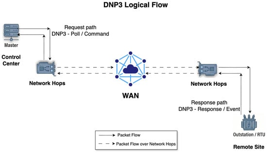
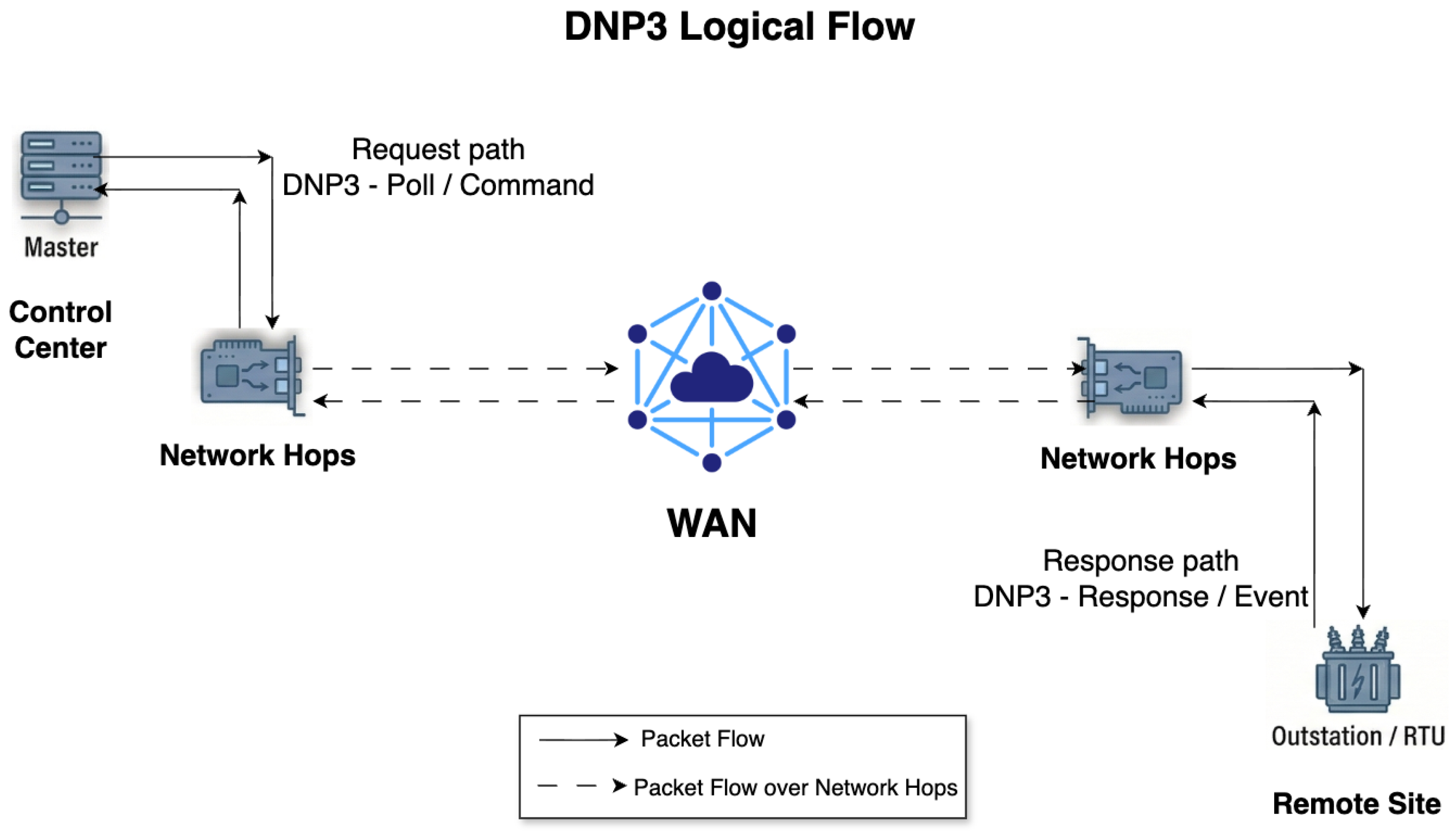
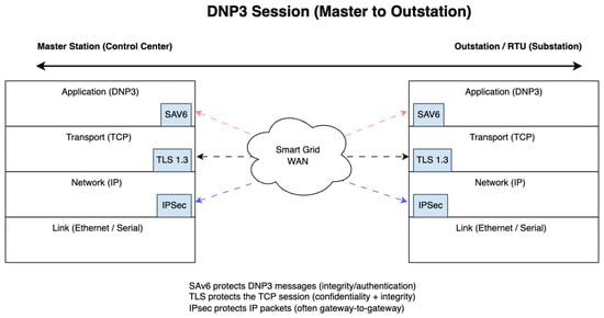
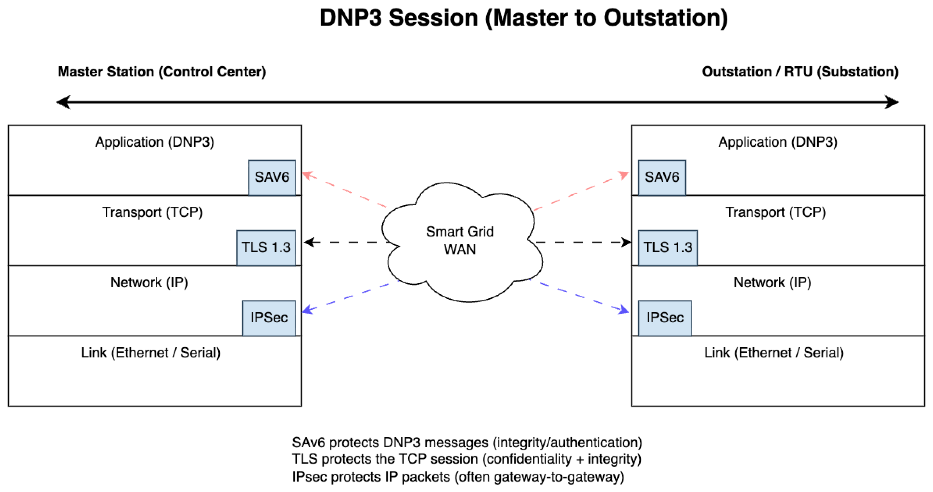
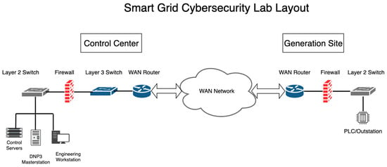
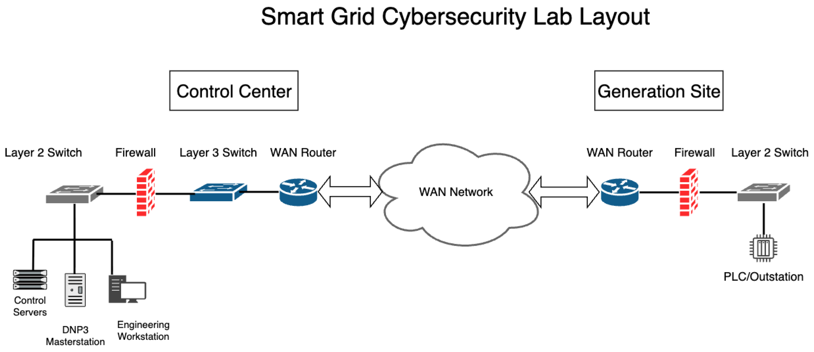
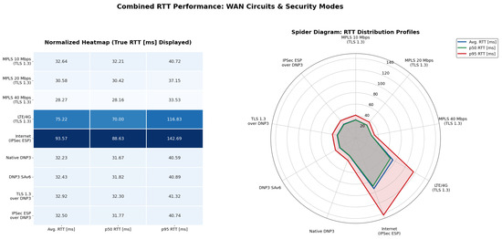
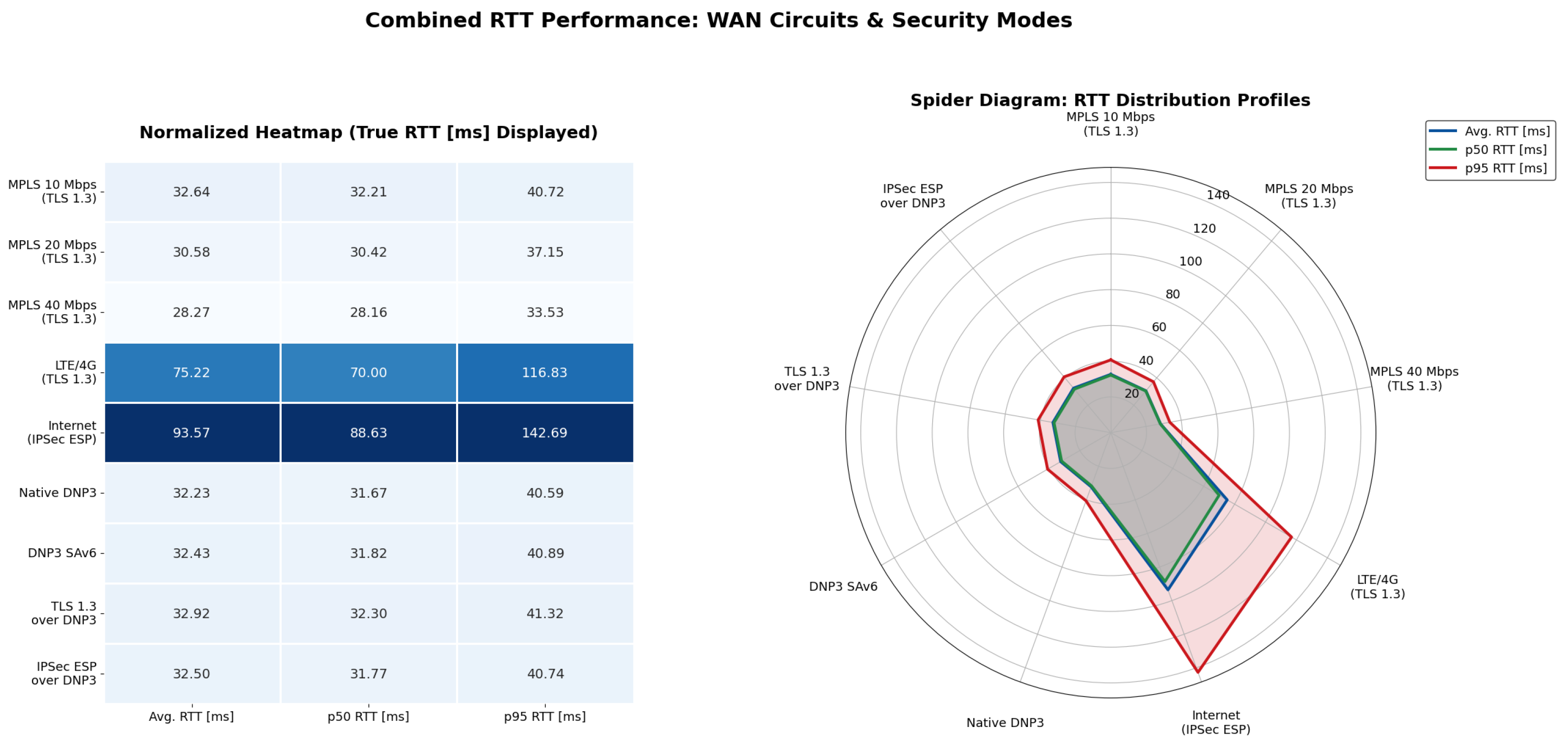
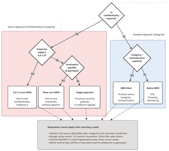
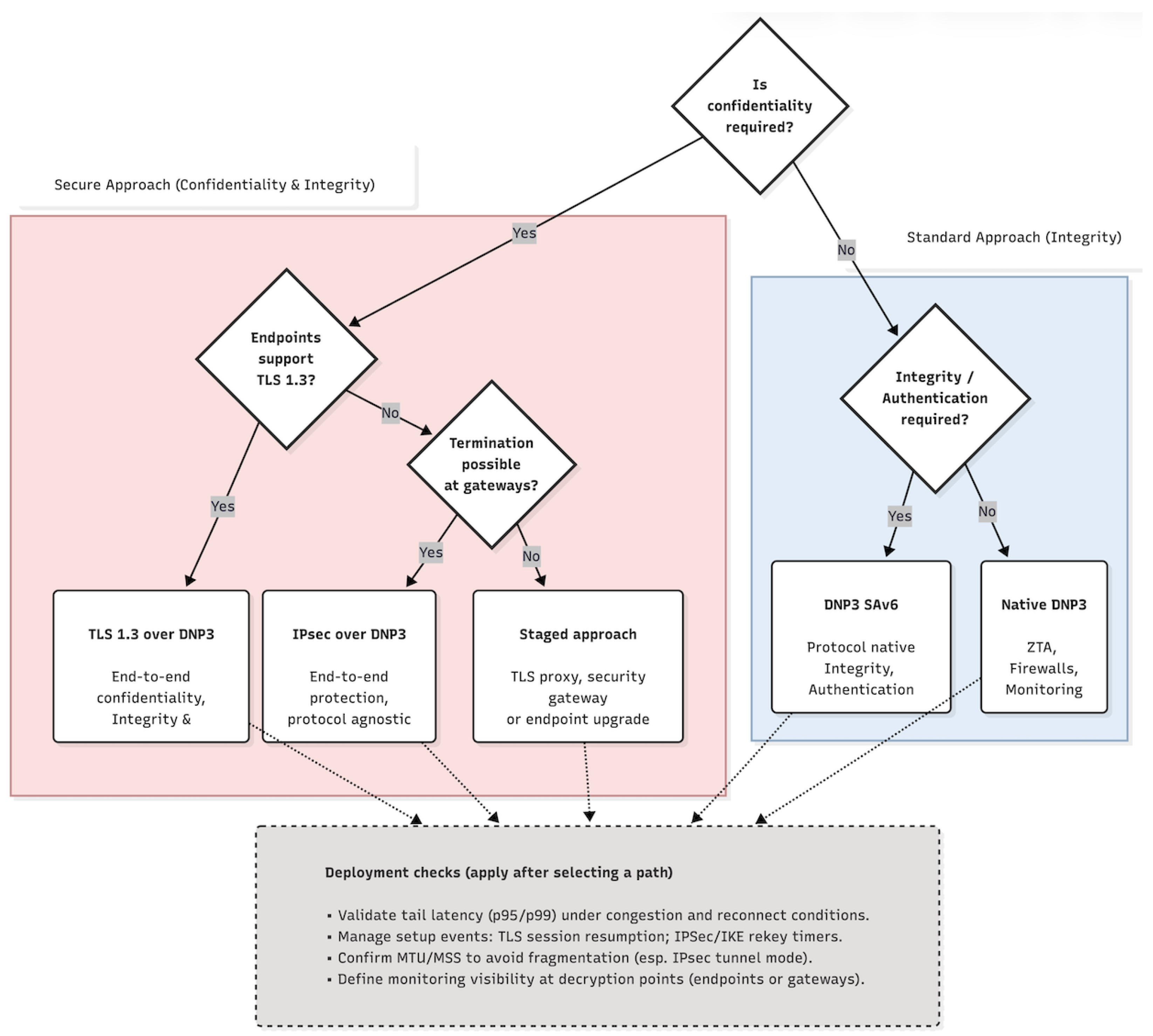

Disclaimer/Publisher’s Note: The statements, opinions and data contained in all publications are solely those of the individual author(s) and contributor(s) and not of MDPI and/or the editor(s). MDPI and/or the editor(s) disclaim responsibility for any injury to people or property resulting from any ideas, methods, instructions or products referred to in the content. |
© 2026 by the authors. Licensee MDPI, Basel, Switzerland. This article is an open access article distributed under the terms and conditions of the Creative Commons Attribution (CC BY) license.