


Abstract
We developed a metal-compatible RFID dipole antenna. The antenna consists of three layers, including the top metal, dielectric substrate, and bottom metal, with the top metal and bottom metal of the dipole antenna shorted at the side edges of the antenna. In order to accurately measure the gain and reflection coefficient (|S11|) of the antenna in the desired frequency band, an impedance matching circuit was created using an open stub around the feeding section of the antenna. The simulation and measurement results of the |S11| and antenna’s realized gain are presented in this paper. The measured |S11| has similar characteristics to the design results at around 915–940 MHz. The size of the proposed antenna is 70 mm × 50 mm × 1.636 mm. In addition, the antenna can be bent at 0, 3, or 5 divisions to fit curved metal objects such as lithium-ion batteries (LIBs). This antenna structure is a fundamental area of study for future application to flexible substrates. Conductive adhesive tape (copper tape) was used to connect each section. The surface of the copper tape was fixed with adhesive to prevent it from peeling off. In the simulation and measurement, it was confirmed that our proposed antenna could operate around the desired frequency band. In the future, we plan to install an IC chip in the antenna input section and work towards implementing it in society.
1. Introduction
In recent years, RFID tags have been gaining attention as a technology that assigns information to objects across various fields such as logistics and IoT solutions [1]. Electronic tags consist of IC chips that store ID information and can output and input ID information via wireless communication [2]. RFID is an automatic recognition technology using such electronic tags with antennas. It is expected to be utilized for waste collection and treatment. With the increase in mobile devices, there have been accidents where lithium-ion batteries (LIBs) have been mixed in with waste, causing smoke and fire during crushing processes. If LIBs are present at the loading ports of packer trucks or crushing equipment at recycling facilities, they may ignite due to excessive compression or crushing of the LIBs [3,4,5,6,7]. The purpose of this study is to develop an RFID tag antenna to detect and collect such LIBs safely and efficiently. Conventional electronic tags do not function well because the antenna is attached to metal, which blocks the radio waves emitted from the antenna. Therefore, we have developed a small, planar, dipole antenna that can be attached to metal waste. The proposed antenna is for 900 MHz RFID tags that can be used for various forms of metal waste other than LIBs. Among the various ultra-high-frequency bands (UHF: 300 MHz to 3 GHz), technologies utilizing the 900 MHz band are becoming extremely popular as an IoT solution with a wide range of social contributions [8,9]. Currently, except for the European band (from 800 MHz to 865 MHz), the RFID frequency range around the world is from 900 MHz to 950 MHz [10]. The Japanese RFID standard is from 915 MHz to 930 MHz. Therefore, various antennas have been proposed to operate in this frequency band [2,10,11,12]. However, radio waves are affected by various metals in their vicinity [11]. For example, if an antenna is placed in front of a metal object, the radio waves will be blocked or reflected by the metal. This factor has a negative effect on the antenna directivity (radiation pattern). Therefore, to attach RFID tags to various products that contain metal, metal-compatible antennas must be used. A variety of metal-compatible antennas have been designed so far, but these antennas are designed to be attached to relatively large metal objects. RFID requires the design of miniature antennas that can be attached to small metal objects, not just clothing tags or product price tags. An RFID tag antenna whose antenna gain does not decrease even when attached to a metal surface was developed in this research. A patch antenna has such characteristics. It has been commonly used in metal-compatible antennas. Due to its electromagnetic radiation characteristics, this antenna has high gain, a wide bandwidth, and a simple antenna shape, making it inexpensive and easy to mass-produce [12]. However, large antenna elements, ground metal planes, and relatively thick dielectric substrates are necessary to ensure the adequate performance of these antennas. In addition, because patch antennas require a length of half a wavelength, it is difficult to reduce the antenna size, making them unsuitable for small devices such as RFID tags and IoT products. Moreover, patch antennas are not suitable for connection to surface-mounted IC chips because the GND feeding point is located on the bottom layer. Therefore, we focused on the dipole antenna, which is a differential circuit that can be directly connected to an IC chip. Commercially available RFID dipole antennas (typically non-metal-compatible antennas) are half a wavelength in size and have a gain of about 2 dBi [13]. On the other hand, metal-compatible antennas cannot completely prevent interference from radio waves emitted from metal objects, so they are larger in size and have significantly lower gain than non-metal-compatible antennas. Therefore, we designed a one-sided directional antenna by connecting a floating metal with no electrical connection to the back of the antenna and blocking the radio waves emitted from the back of the antenna. In this paper, the antenna design is presented in Section 2, and the fabrication of the antenna and the measurement results of the proposed antenna are shown in Section 3. Finally, our conclusions and ideas for future works are presented in Section 4.
2. Antenna Element Design
We looked into designing a metal-compatible dipole antenna. Next, we designed an antenna that could be folded and bent to attach to objects of various shapes.
2.1. A Metal-Compatible Dipole Antenna
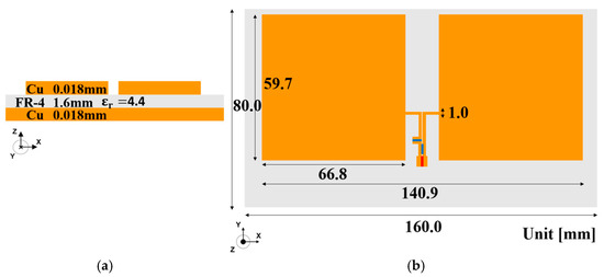
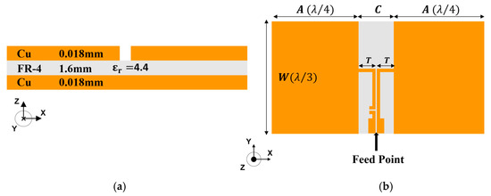
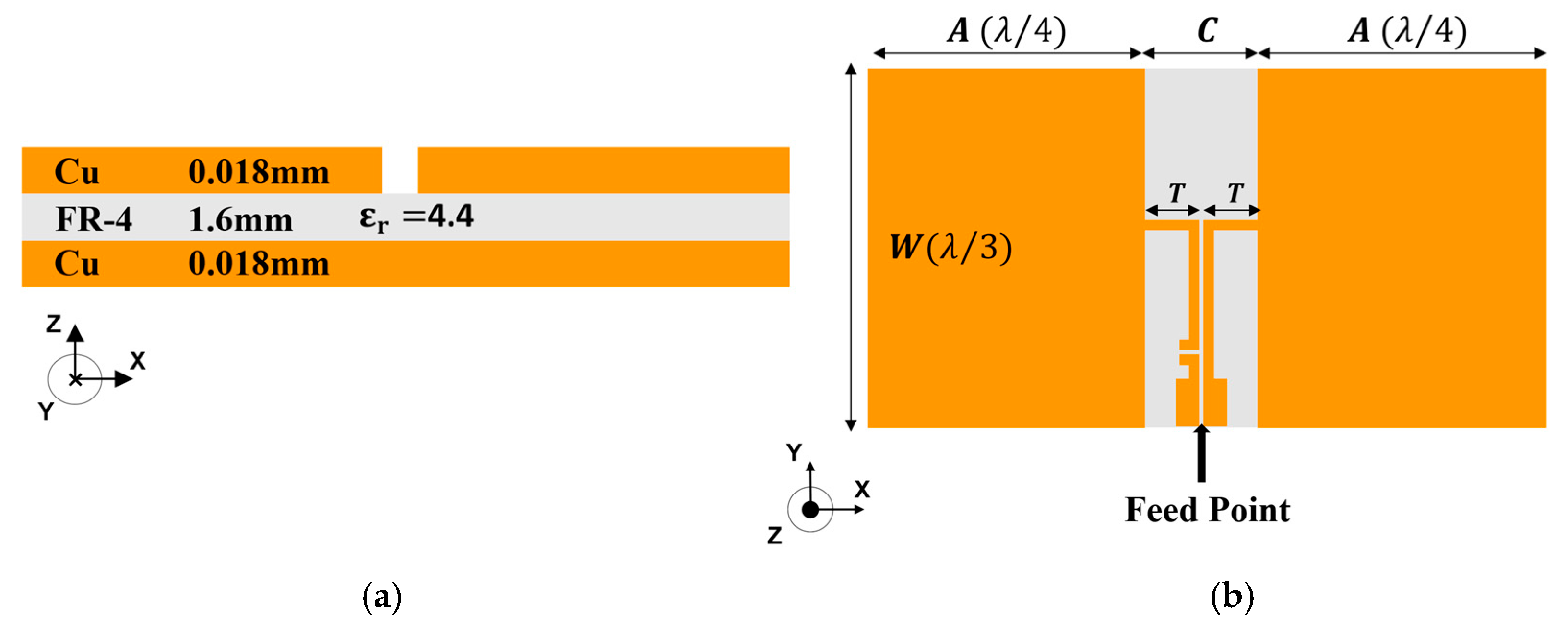
We designed a metal-compatible dipole antenna to operate in the 900 MHz band [14]. Figure 1a,b show the antenna layout. The antenna size is 160 mm × 80 mm × 1.6 mm. The antenna is composed of two layers, a top and a bottom metal dielectric substrate.
Figure 1.
Layout of designed dipole antenna element. (a) Side view. (b) Top view [14].
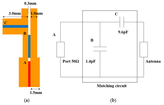
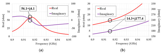
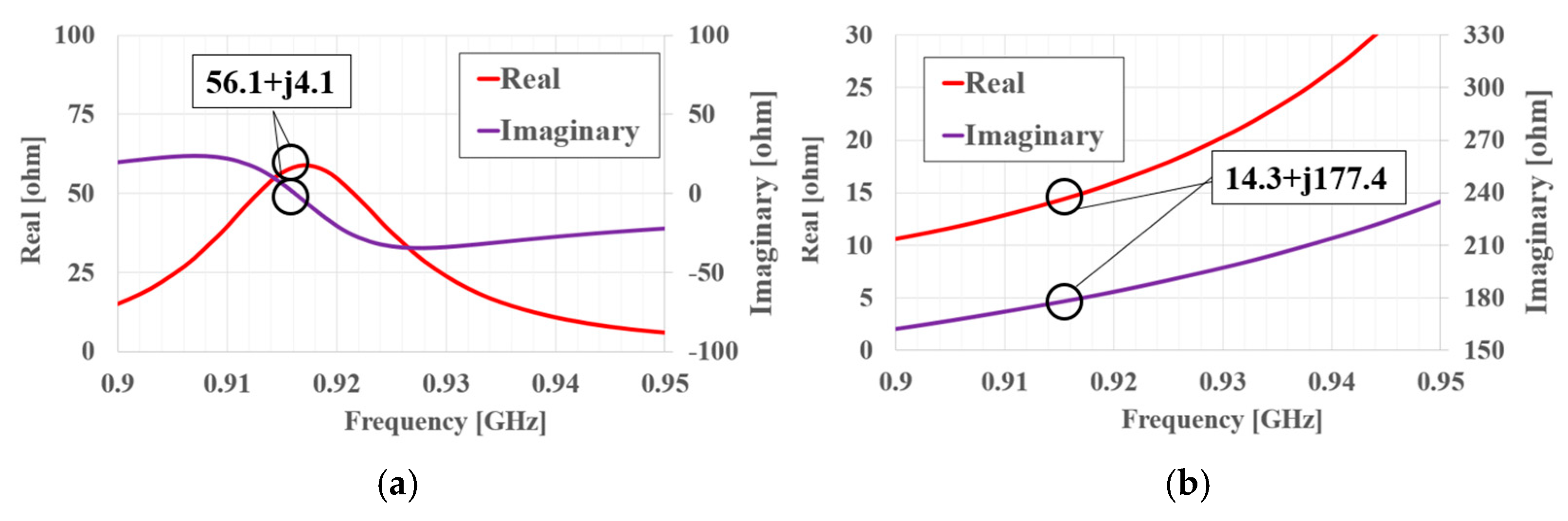
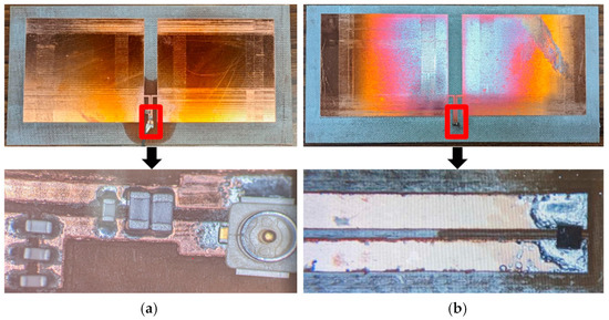
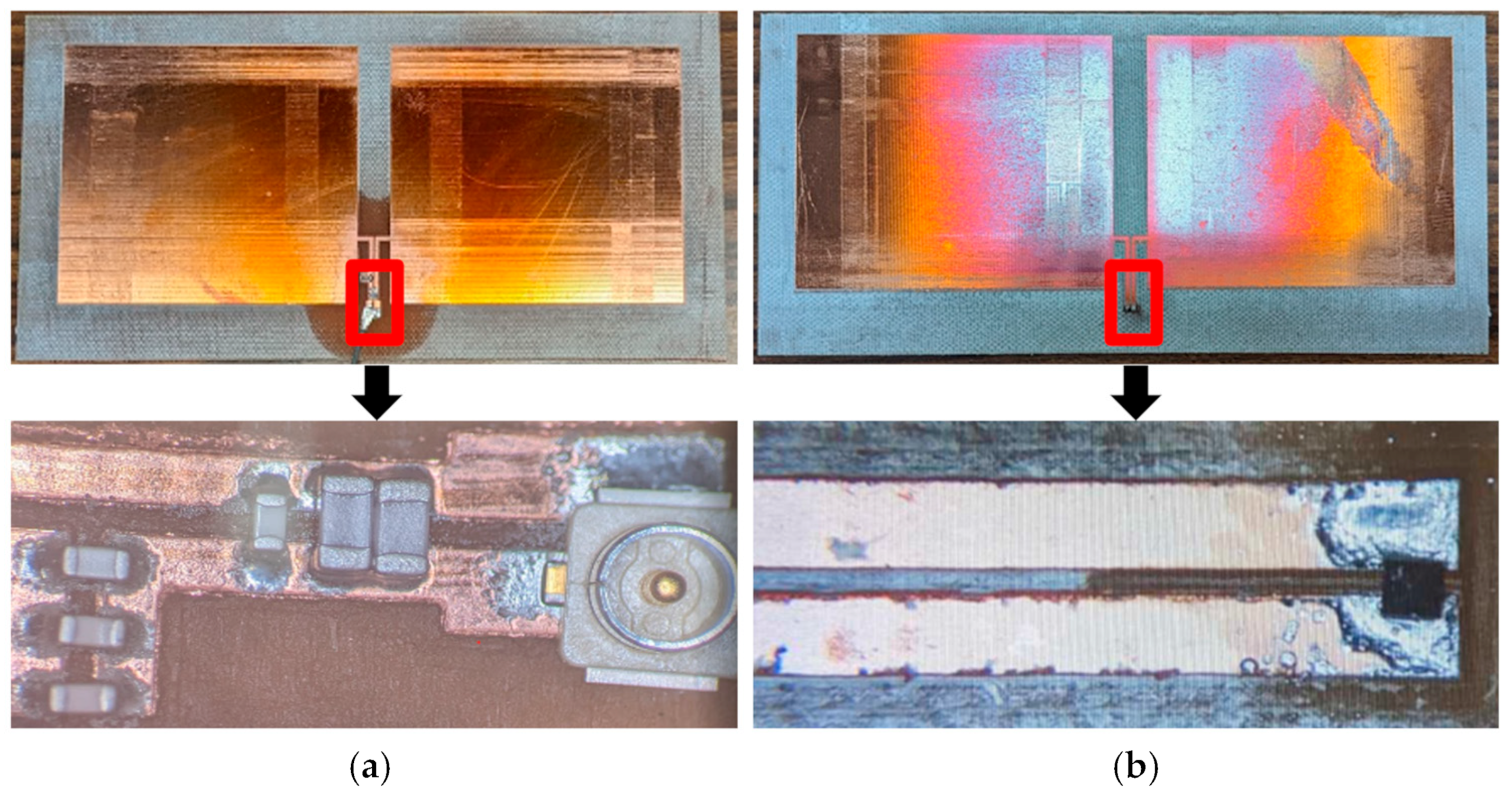
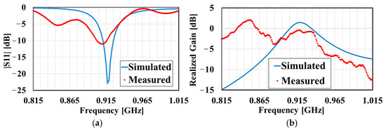
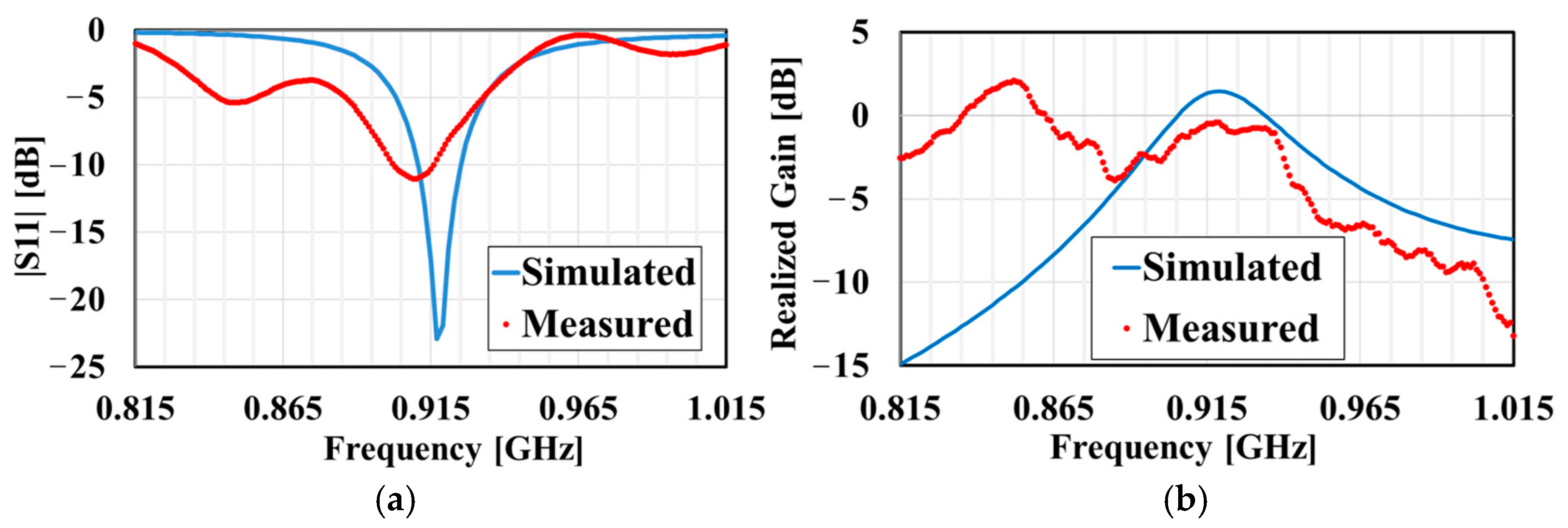
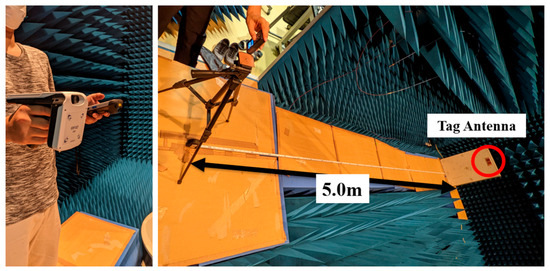
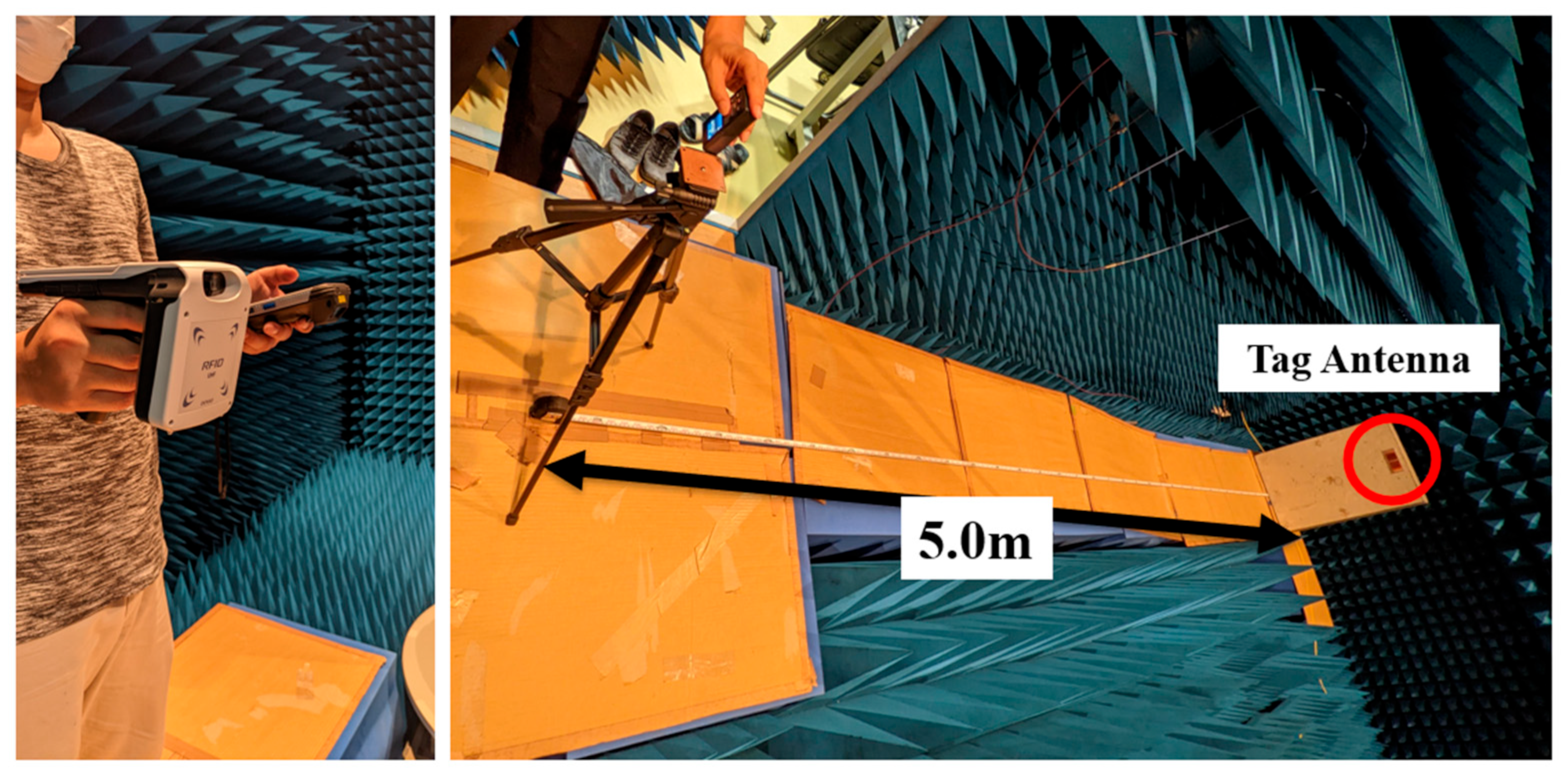
The dielectric substrate is a 1.6 mm thick FR-4 substrate (dielectric constant ε r = 4.4; dielectric loss tangent tan δ = 0.018 @1.0 MHz). The bottom metal has no electrical connection to the top metal, i.e., it is a floating metal layer. The RFID tag antenna is impedance-matched to the IC chip. However, a 50 Ω measurement system was used to evaluate high-frequency characteristics, making it difficult to measure the antenna alone. Therefore, by adding an impedance matching circuit using a chip capacitor only to the signal feed section without changing the layout of the antenna radiation section, it became possible to measure the antenna characteristics with the conventional measurement system. For electromagnetic field analysis, 3D electromagnetic simulator (HFSS version 10.1, Ansoft) was utilized. Figure 2a,b show the impedance matching circuit and its equivalent circuit for a metal-compatible dipole antenna. Figure 3 shows the electric field of the top surface of the substrate at 915 MHz. As can be seen from the electric field distribution, this antenna operates as an open-ended dipole antenna. Taking this dielectric constant into account, the half wavelength of the antenna is 7.9 mm. This length is half the wavelength of the fundamental operating mode of the dipole antenna. The impedance of the chip should be matched at 16 + j181 Ω [15]. Figure 4a shows an antenna with impedance matched to around 50 Ω. Figure 4a shows a simulated antenna with impedance matched to around 16 + j181 Ω. As a result, these impedances allow the IC chip-loaded antenna to operate [r3_1]. Figure 5a,b show a photograph of the proposed dipole antenna. A vector network analyzer with a 50 Ω port was used to measure the characteristics of the antenna alone. Therefore, an impedance matching circuit was added to the input section. As shown in Figure 5, when loading an IC chip, it will be implemented using a T-match technique. The RF signal is provided by a coaxial cable, an SMA-to-UFL conversion cable, and a U. FL connector. The IC chip is NXP’s UCODE 7xm, with an impedance of 16 − j181 Ω [15]. Figure 6 shows the design results of a typical dipole antenna [16]. Radiation is affected by the parasitic capacitance of lumped chip elements. Therefore, the measured realized gain is lower than the simulated realized gain. Figure 7 shows the experimental setup for the RFID reader–writer (R/W) system (SP1-QUBi BT-SP1LA-C, SP1 RFID Scanner, DENSO WAVE) with our proposed antenna. This experiment was conducted in an anechoic chamber [14]. We were able to establish communication between the R/W system and our antenna equipped with an IC chip at a distance of 5 m [10,16]. Our results show that if we can design this antenna at 50 Ω, it can also be matched to the impedance of the IC chip. Table 1 shows a comparison with metal-compatible small antennas for UHF RFID designed within the last four years. These tags are greatly affected by the shape of the metal on the back. The tag in [17] is very small with high gain but works on the assumption that there is metal on the back side. In addition, the tags in [18,19,20] are small, but their performance per unit volume is not much different from that of the designed antenna, considering the sensitivity of the IC chip, TX power, and communication distance. The antenna of this research is excellent, and stable gain can be obtained regardless of the presence or absence of metal and the effect of its size.
Figure 2.
(a) Layout of impedance matching circuit for Figure 1b; (b) equivalent circuit of (a) [14].
Figure 3.
Simulated electric field of top surface of substrate at 915 MHz [14].
Figure 4.
Simulated antenna with impedance matched to 50 Ω (a) and matched to that of IC chip (b).
Figure 5.
A photograph of the proposed dipole antenna. (a) The top surface of the proposed dipole antenna and the feeding section of the antenna with the 50 Ω impedance matching circuit. (b) The top surface of the proposed dipole antenna and the feeding section of the antenna with the IC chip [14,21].
Figure 6.
(a) Frequency characteristics of simulated and measured reflection coefficients (|S11|). (b) Frequency characteristics of simulated and measured antenna gains.
Figure 7.
Experimental setup for RFID reader–writer system [14].
Table 1.
Comparison of metal-available UHF tag antennas [15,17,18,19,20].
2.2. Antenna Design for Miniaturization
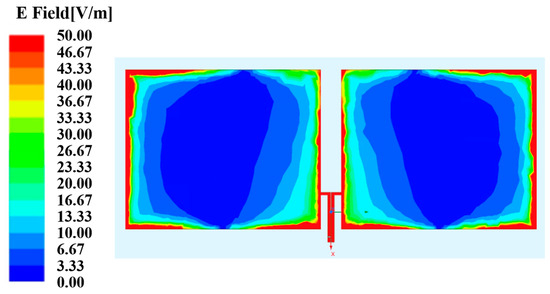
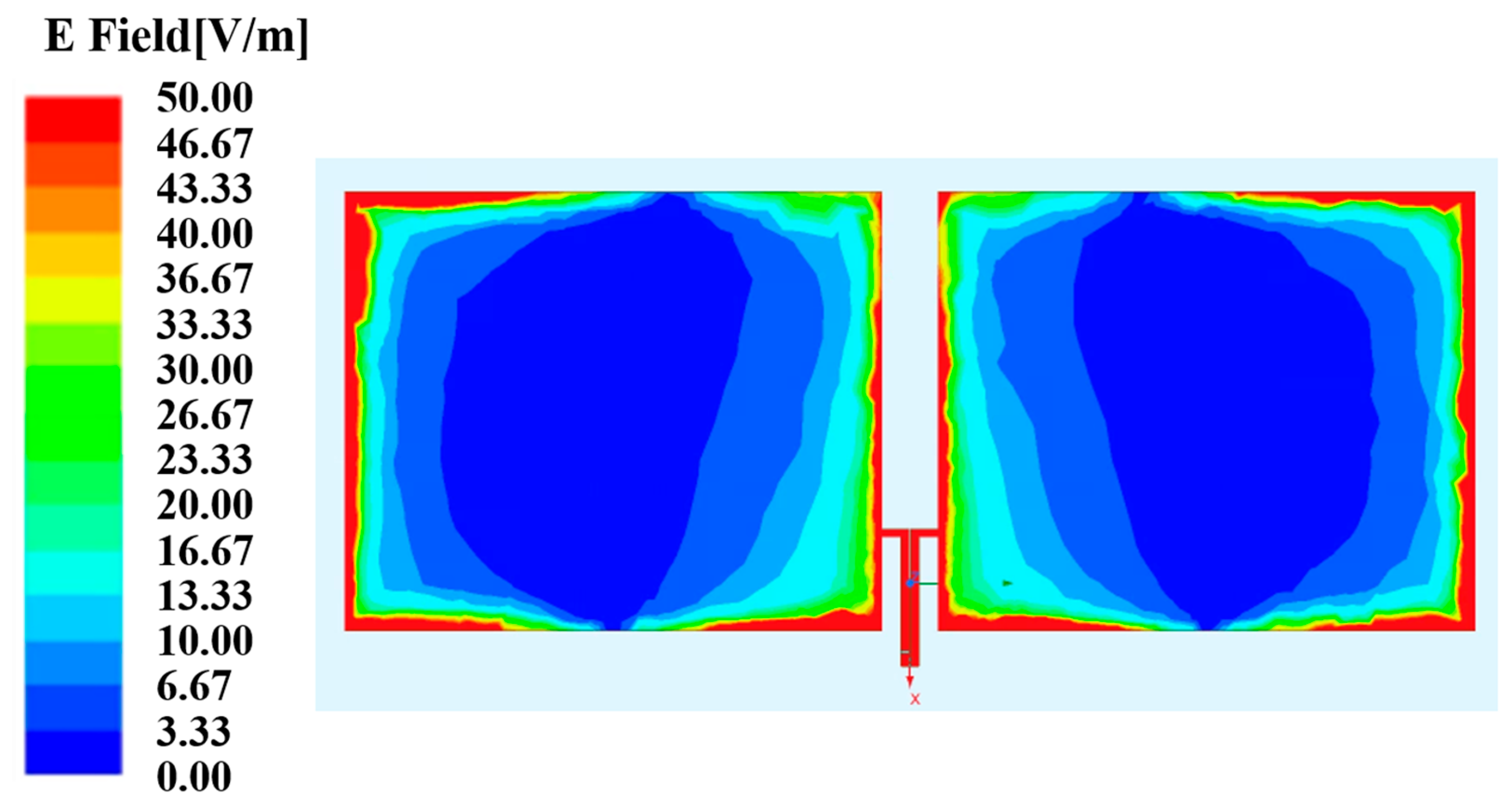
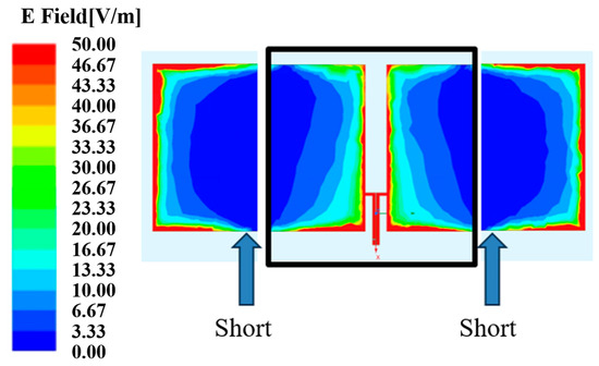
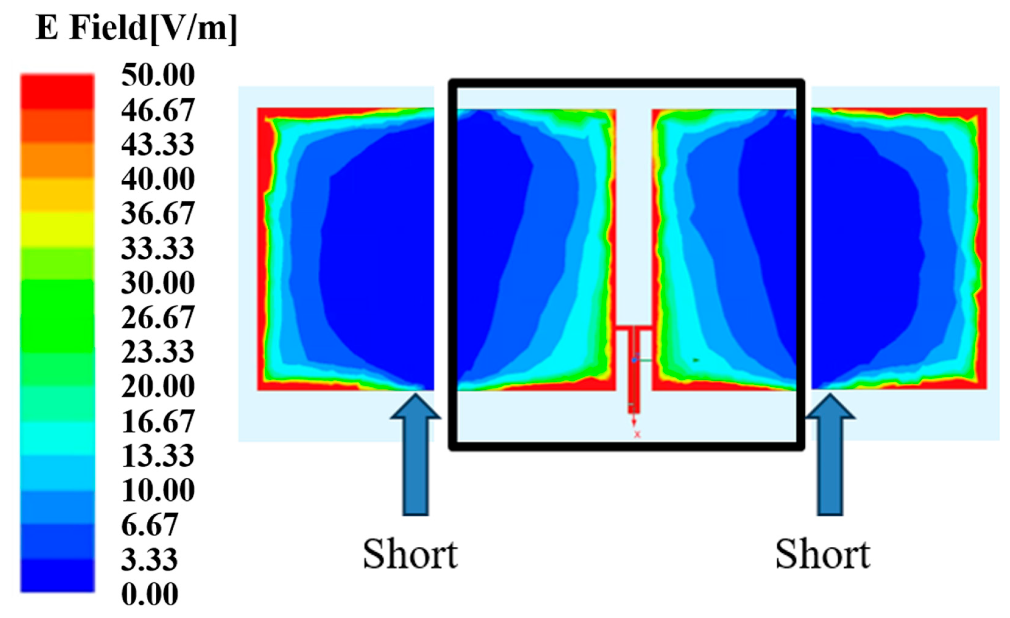
In Section 2.1, the size of the antenna was large compared to general RFID tags [22,23]. This large antenna size limits the objects to which it can be attached. To make it compact, we designed an antenna that can operate at a length of a quarter of the wavelength. The electric field distribution of the antenna is shown in Figure 8. The antenna in Figure 3 has a resonator length of λ/2, and both ends are open. The blue part in the figure has an electric field of 0 V/m and can be considered a short circuit. The antenna size was reduced by cutting this part and operating it at λ/4. The cut position is shown in Figure 8. This made it possible to miniaturize the antenna.
Figure 8.
Simulated electric field of top surface of substrate and cutting point at a quarter of the wavelength.
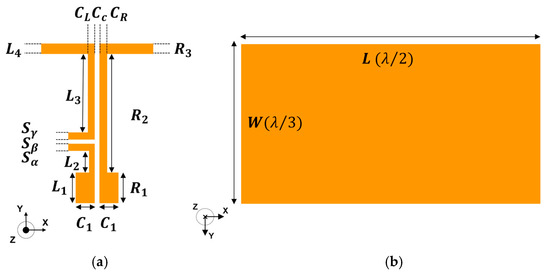
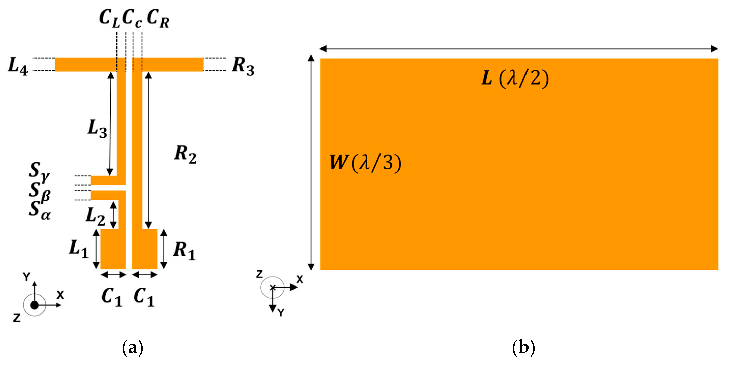
The antenna structure is shown in Figure 9 and Figure 10. Figure 9a shows a side view of the antenna, and Figure 1 shows the antenna top metal. Figure 10a shows an enlarged view of the signal input line in Figure 9b. An open stub is used to achieve impedance matching. Figure 10b shows the bottom surface of the antenna. Table 2 shows the design parameters of the proposed antenna. According to the results in Section 2.1, radiation is affected by the parasitic elements in the chip capacitors. Therefore, this antenna was designed without any chip capacitors.
Figure 9.
(a) Antenna layer (side view). (b) Antenna top metal (top view).
Figure 10.
(a) Impedance matching section from Figure 9b. (b) Antenna (bottom metal).
Table 2.
Proposed antenna parameters (unit [mm]).
2.3. Antenna with Bending (3,5 Division)
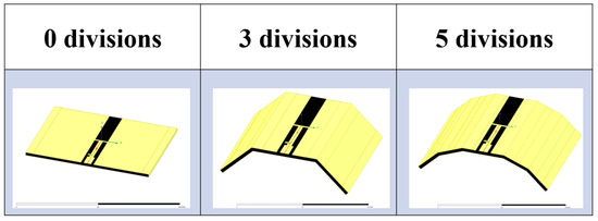
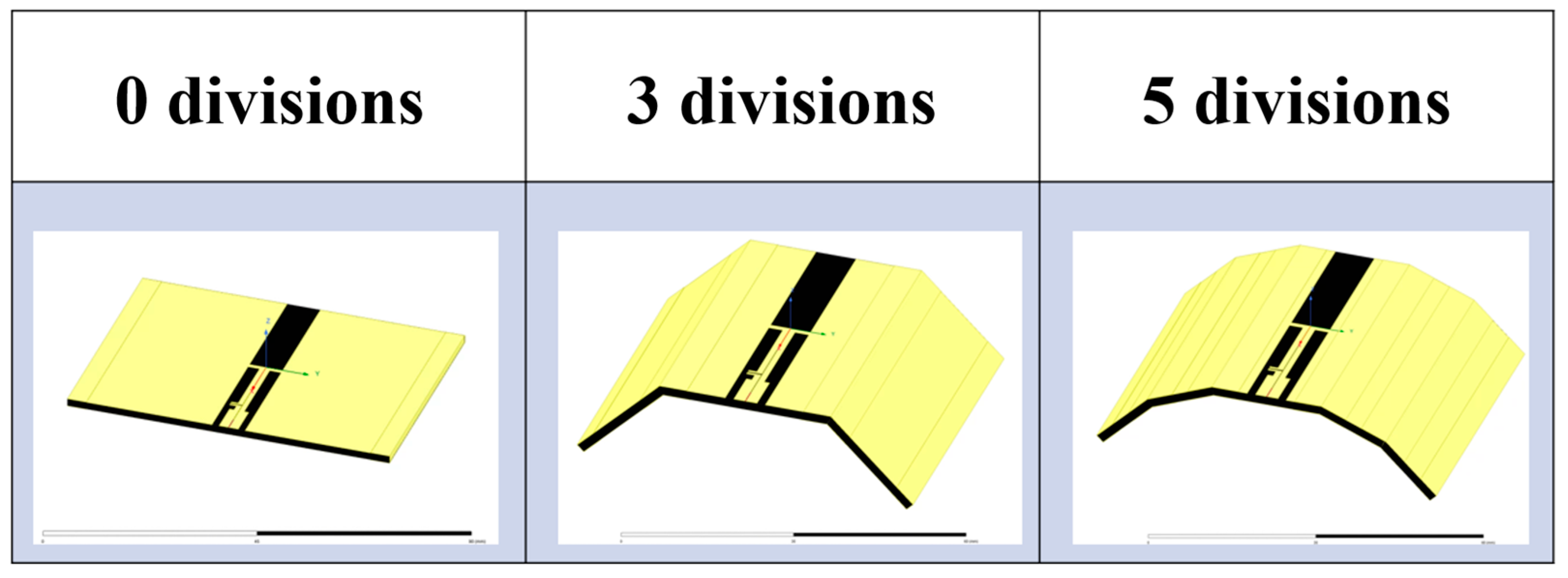
Although we succeeded in designing a metal-compatible antenna, as the antenna shape is limited to flat surfaces, the objects to which it can be attached are limited. Therefore, we developed a 900 MHz band RFID tag antenna that can be used for LIBs and various shapes of metal objects and waste. And we developed antennas that can be bent into 0, 3, and 5 divisions. The structures of each of the proposed antennas are shown in Figure 11. This antenna is a fundamental area of study for future antennas using flexible substrates. Because the original substrate is rigid, it is cut, divided, and then connected to virtually achieve bending.
Figure 11.
The respective structures of the proposed antenna that have 0, 3, and 5 divisions.
3. Results and Discussion
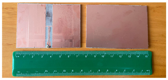
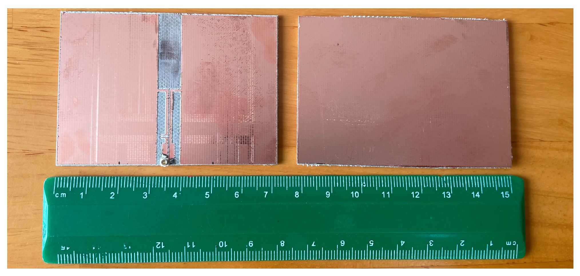
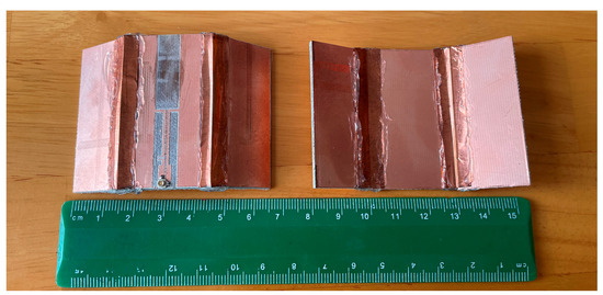
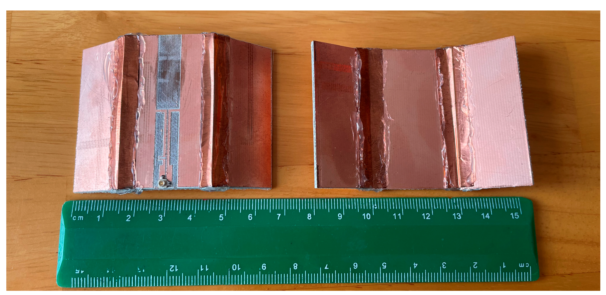
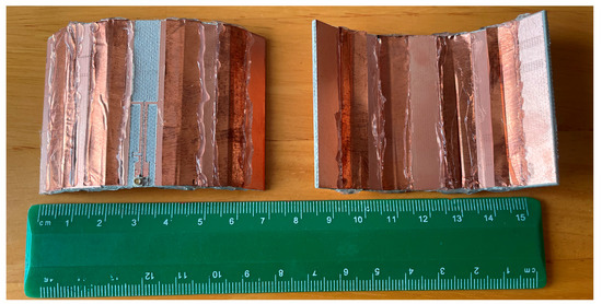
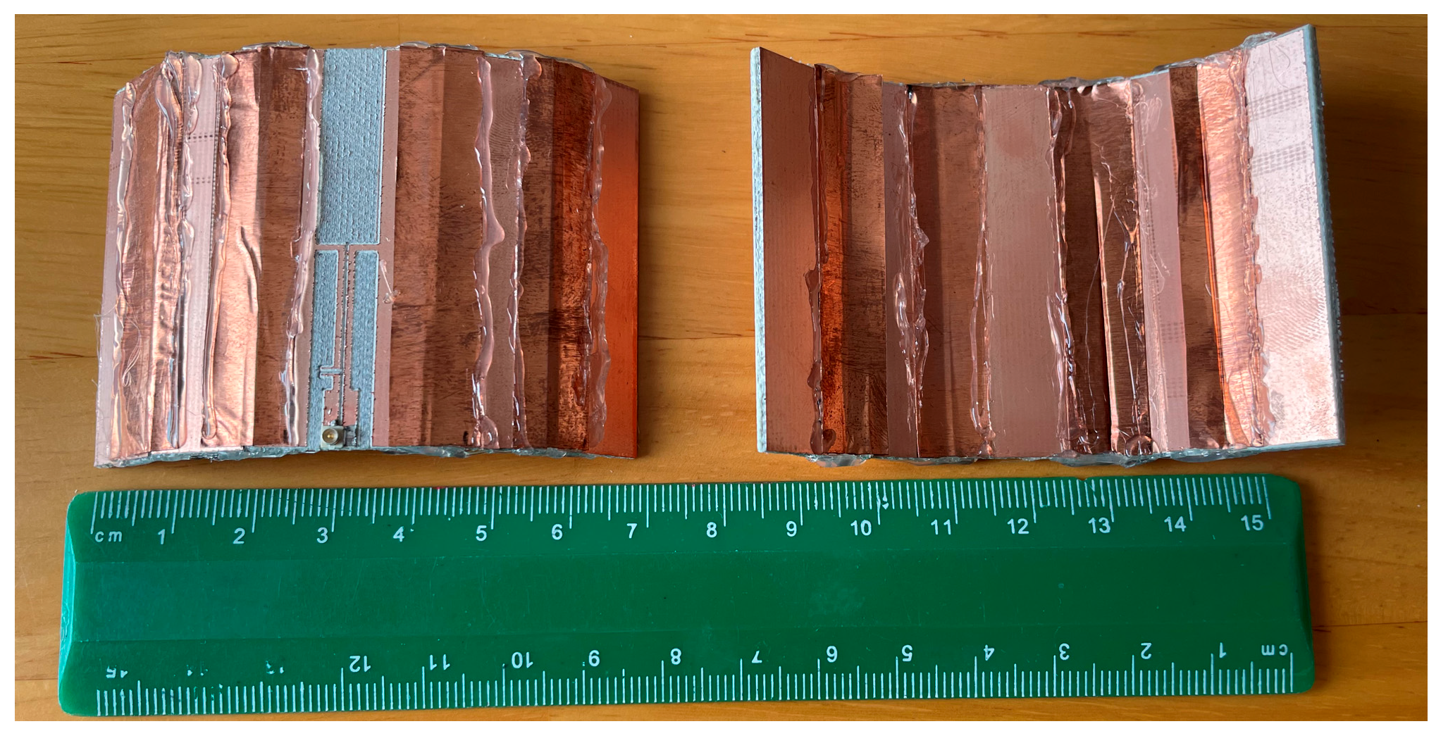
The proposed prototype antenna is shown in Figure 12, Figure 13 and Figure 14. This prototype was made using a MITSUI FP-21T processing machine manufactured by the MITS Corporation. The size of the antenna is 50 mm × 70 mm × 1.6 mm. The MMCX connector was used as the signal feed point. Conductive adhesive tape (copper tape) was used to connect the cut parts of the antenna, and an adhesive was applied to the surface of the copper tape to prevent it from peeling off.
Figure 12.
A photograph of the proposed antenna with 0 divisions.
Figure 13.
A photograph of the proposed antenna with 3 divisions.
Figure 14.
A photograph of the proposed antenna with 5 divisions.
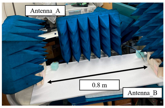
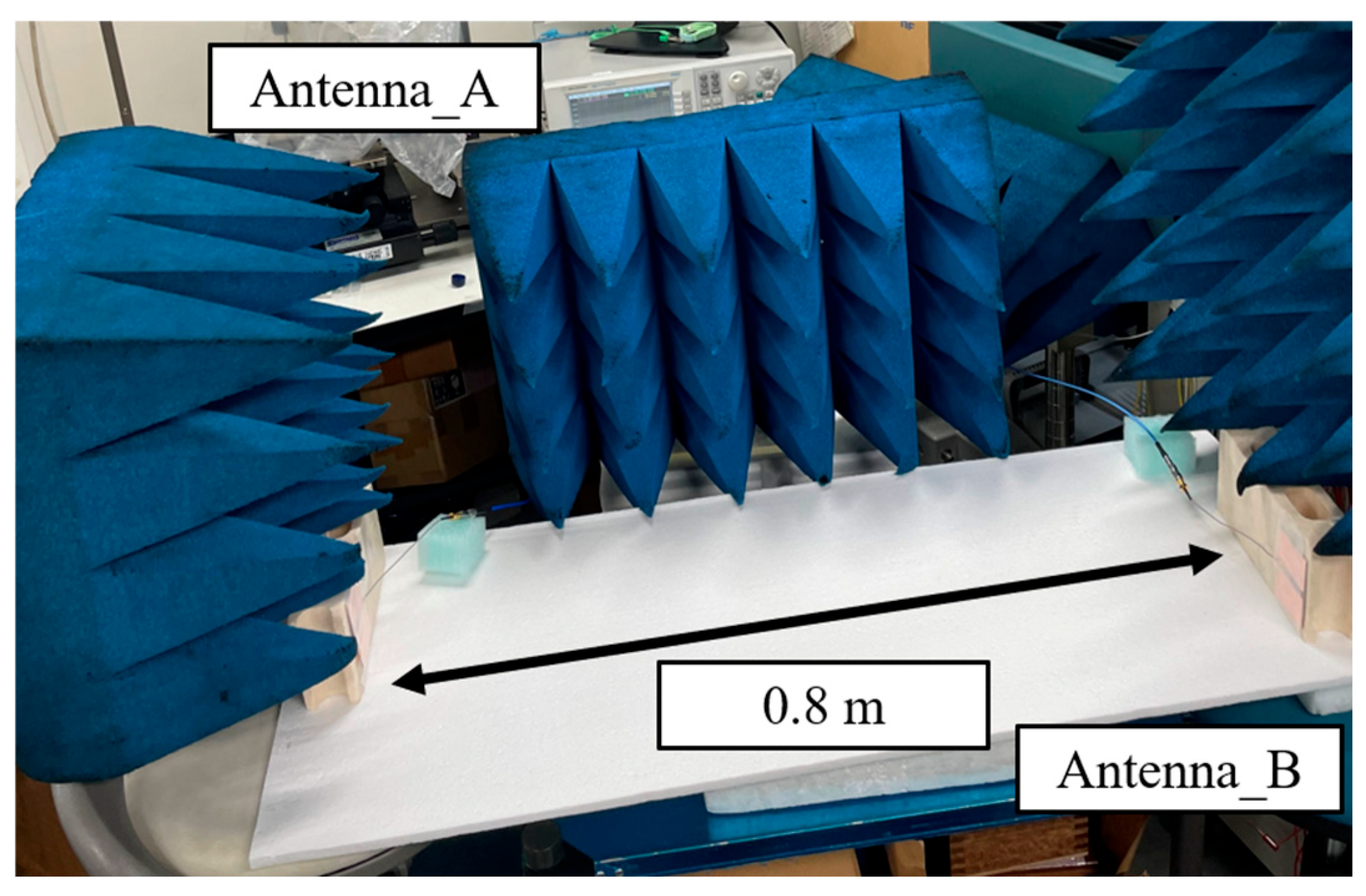
Figure 15 shows a photograph of the experimental setup for |S11| and gain measurement. The S-parameters were measured using a network analyzer (HP: HP8722C, Hewlett-Packard Company, Palo Alto, CA, USA Anritsu: Anritsu 37269D ANRITSU CORPORATION, Atsugi, Janan). To measure the transmission characteristics, a coaxial cable and a prototype antenna were connected to Port 1 and Port 2 of the network analyzer, respectively. The antenna on Port 1 was used as the transmitting antenna, and the antenna on Port 2 was used as the receiving antenna. Then, we place the antennas facing each other and measured |S21|. Based on the measured |S21| and transmission distance, the Friis transmission formula was used to obtain the gain frequency characteristic [24].
Figure 15.
Photograph of experimental setup for |S11| and gain measurement.
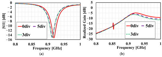
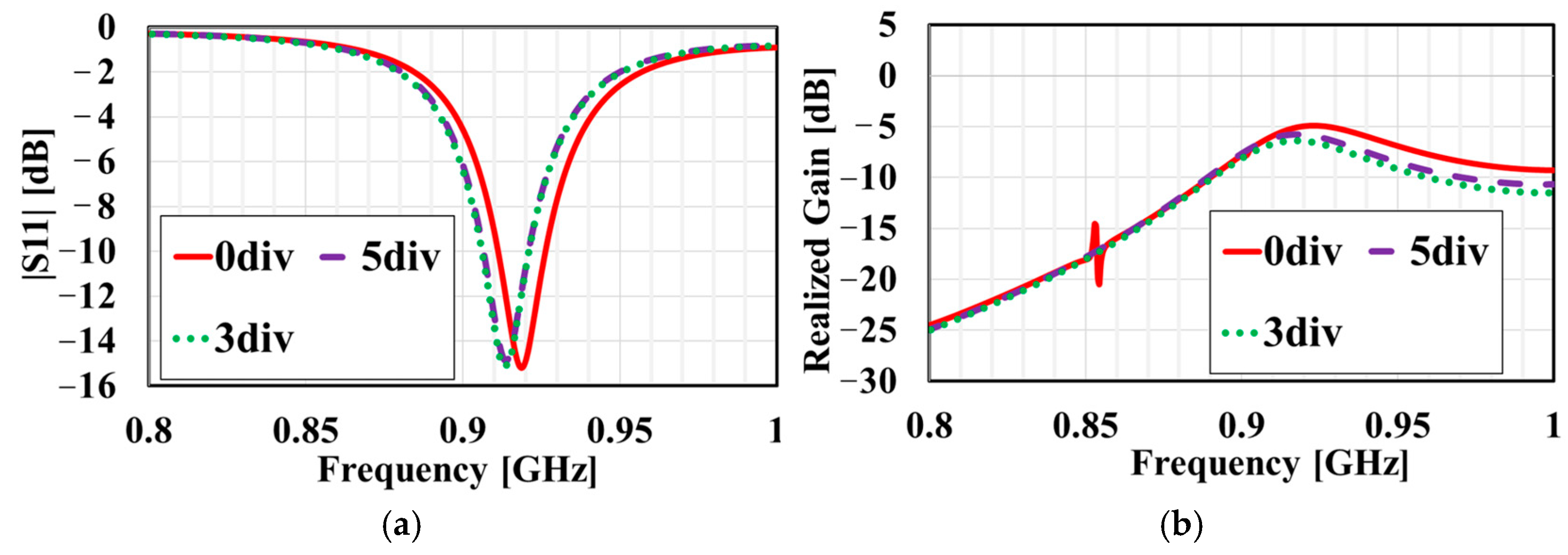
Figure 16a,b and Table 3 and Table 4 show the differences in the frequency characteristics of the proposed prototype antennas for the simulation. As shown in Figure 16a and Table 3, the |S11| characteristics achieved the desired frequency bands for RFID.
Figure 16.
Frequency dependence of (a) |S11| and (b) realized gain of 0, 3, and 5 divisions for simulated value.
Table 3.
Comparison table of simulations |S11|.
Table 4.
Comparison table of measured realized gain.
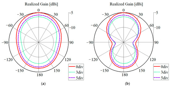
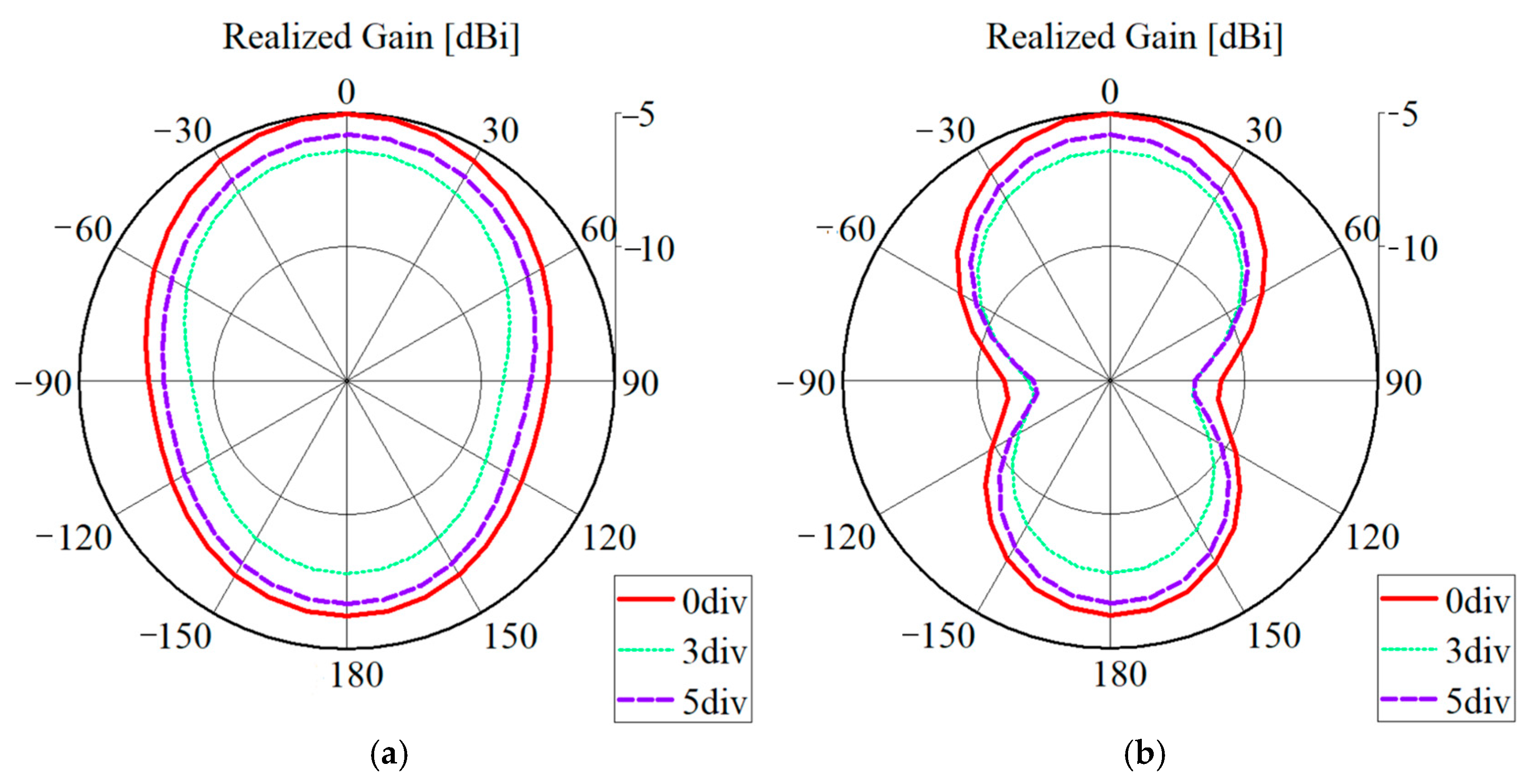
As shown in Figure 16b and Table 4, we designed these antennas to have a wide bandwidth in the 900MHz band. Figure 17 shows the radiation patterns of the bent and unbent antennas. These radiation patterns are at each of their respective resonant frequencies. Regardless of the resonant frequency, the bent antenna has reduced realized gain compared to the unbent antenna. Even if the value of |S11| is the same, the use of conductive adhesive tape (copper tape) increases the conductor resistance and reduces the radiation resistance. Therefore, the bent antenna has the effect of reducing gain.
Figure 17.
The division dependence of the simulated radiation pattern of the antenna. (a) The xz-plane and (b) The yz-plane.
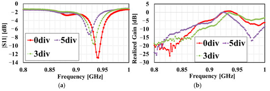
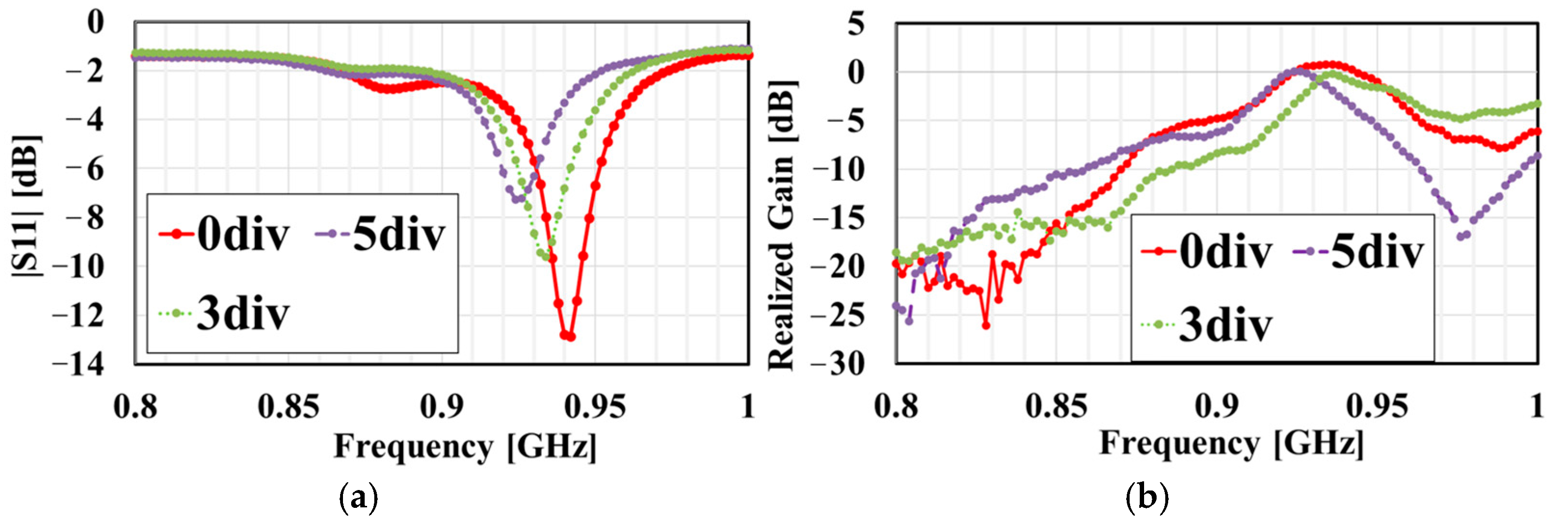
Figure 18 shows the frequency dependence of the |S11| of 0, 3, and 5 divisions for the measurements. As a result of the results shown in Figure 18 and Table 5, the measured value of |S11| shifts to the lower-frequency side by increasing the number of divisions. The use of conductive adhesive tape (copper tape) contributes to the length of the antenna resonator. As the number of divisions increases, the frequency shifts toward the lower-frequency side. This shift is due to the use of copper tape to increase the length of the antenna resonator. However, according to Table 6 and Figure 18, the realized gains of the antennas are increased. This is caused by the difference in tan δ of the substrate. In addition, the frequency dependence of |S11| is shifted to the high-frequency region. This difference is caused by the solder used to connect the antenna to the connector, by changes in the dielectric constant of the FR-4 board, and even by the precision of the small stub components when fabricating the antenna on a PCB machine. This measurement gives rise to differences in bandwidth. However, a simulation can also be performed to change the impedance using an impedance matching circuit to achieve the desired frequency band. Moreover, small spaces are created when connecting the cut ends of each antenna division. The more divisions there are, the greater the effect. This is also improved by the increase in radiation. In particular, with five divisions, the number of cut points increases, and an unnecessary attenuation pole occurs on the wideband side. Table 5 and Table 6 show a comparison of the measured |S11| and realized gain. Even when divided into five parts, it is still useful for RFID applications.
Figure 18.
Frequency dependence of (a) |S11| and (b) realized gain of 0, 3, and 5 divisions for measured value.
Table 5.
Comparison table of the measured |S11|.
Table 6.
Comparison table of the measured realized gain [r2_7].
4. Conclusions and Future Works
In this study, we developed metal-compatible dipole antenna for RFID application. An RFID tag that operates in the 900 MHz band was developed that can be used with LIBs and other metal objects of various shapes, as well as waste. Therefore, we developed antennas that are bent into 0, 3, and 5 divisions. Our results show that the unbent antenna (0 div) achieved a realized gain of 0.75 dBi, sufficient bandwidth for an RFID of 6 MHz. In addition, the resonator length of the antennas was lengthened, and the frequency shifted to the lower side upon bending the antenna. But the realized gain of all the antennas was −1 dBi or more. In the future, we plan to verify the operation and characteristics of the antenna when attached to metal or other surfaces. In addition, we plan to work towards implementing the antenna’s practical use in society by equipping the antenna power supply section with an IC chip. Furthermore, in order to confirm the impact on reception, we plan to conduct tag reading experiments by placing tags not only in an anechoic chamber but also in ordinary living environments for the purpose of assessing the practical application of this detection system. It was experimentally confirmed that our design still functions as an antenna even when bent.
Author Contributions
Conceptualization, K.S. (Kazuki Suehiro); Methodology, K.S. (Kazuki Suehiro), K.N. and K.I.; Validation, K.S. (Kazuki Suehiro); Formal Analysis, K.S. (Kazuki Suehiro); Investigation, K.N., K.I., E.A. and K.Y.; Data Curation, K.S. (Kazuki Suehiro); Writing—Original Draft, K.S. (Kazuki Suehiro); Writing—Review and Editing, K.S. (Kazuki Suehiro) and K.Y.; Visualization, K.S. (Kazuki Suehiro); Supervision, H.K.; Project Administration, K.S. (Koji Sakakibara), K.Y. and H.K. All authors have read and agreed to the published version of the manuscript.
Funding
This research was partly supported by the Resource Circulation IoT Systems Course. The authors would like to express their thanks for funding provided by the course “Material cycle IoT system” at Kyushu University and to the Kanadevia Corporation, Japan, for their helpful support.
Data Availability Statement
The original contributions presented in this study are included in the article. Further inquiries can be directed to the corresponding authors.
Conflicts of Interest
Haruichi Kanaya has received research donation from Kanadevia Corporation, Japan. Because of donation. The funder was not involved in the study design, collection, analysis, interpretation of data, the writing of this article or the decision to submit it for publication. The remaining authors declare that the research was conducted in the absence of any commercial or financial relationships that could be construed as a potential conflict of interest.
References
- Prothro, J.T.; Durgin, G.D.; Griffin, J.D. The Effects of a Metal Ground Plane on RFID Tag Antennas. In Proceedings of the 2006 IEEE Antennas and Propagation Society International Symposium, Albuquerque, NM, USA, 9–14 July 2006; pp. 3241–3244. [Google Scholar]
- Mezzanotte, P.; Palazzi, V.; Alimenti, F.; Roselli, L. Innovative RFID sensors for Internet of Things applications. IEEE J. Microw. 2021, 1, 55–65. [Google Scholar] [CrossRef] [Scilit]
- Nigl, T.; Baldauf, M.; Hohenberger, M.; Pomberger, R. Lithium-Ion Batteries as Ignition Sources in Waste Treatment Process-A Semi-Quantitate Risk Analysis and Assessment of Battery-Caused waste Fires. Processes 2021, 9, 49. [Google Scholar] [CrossRef] [Scilit]
- EPA 530-R-21-002; An Analysis of Lithium-ion Battery Fires in Waste Management and Recycling. US EPA: Washington, DC, USA, 2021.
- Terazono, A. Fire and Other Incidents/Challenges surrounding the Recycling and Disposal Process of Lithium-ion Batteries. Mater. Cycles Waste Manag. Res. 2022, 33, 214–228. [Google Scholar] [CrossRef] [Scilit]
- Tajin, M.A.S.; Jacovic, M.; Dion, G.; Mongan, W.M.; Dandekar, K.R. UHF RFID channel emulation testbed for wireless IoT systems. IEEE Access 2021, 9, 68523–68534. [Google Scholar] [CrossRef] [Scilit] [PubMed]
- Multimedia Communications Center, 920 MHz Band Electronic Tag System Working Group. Survey on International Trends Regarding 920 MHz Band RFID, etc. 2019. Available online: https://www.soumu.go.jp/main_content/000653005.pdf (accessed on 17 October 2024).
- Chen, H.D.; Tsao, Y.H. Low-profile meandered patch antennas for RFID tags mountable on metallic objects. IEEE Antennas Wirel. Propag. Lett. 2010, 9, 118–121. [Google Scholar] [CrossRef] [Scilit]
- Lee, S.R.; Ng, W.H.; Lim, E.H.; Bong, F.L.; Chung, B.K. Compact Magnetic Loop Antenna for Omnidirectional On-Metal UHF Tag Design. IEEE Trans. Antennas Propag. 2020, 68, 765–772. [Google Scholar] [CrossRef] [Scilit]
- Farris, I.; Pizzi, S.; Merenda, M.; Molinaro, A.; Carotenuto, R.; Iera, A. 6lo-RFID: A framework for full integration of smart UHF RFID tags into the Internet of Things. IEEE Netw. 2017, 31, 66–73. [Google Scholar] [CrossRef] [Scilit]
- Kim, S.S.; Kim, S.H.; Bae, J.H.; Yoon, Y.J. Series Chained Patch Phased Array Antenna for mmWave 5G Mobile in Metal Bezel Design. In Proceedings of the 2019 IEEE International Symposium on Antennas and Propagation and USNC-URSI Radio Science Meeting, Atlanta, GA, USA, 7–12 July 2019; pp. 279–280. [Google Scholar]
- Notten, M.; Veenstra, H.; van der Heijden, E.; Dolmans, G.; Jansen, F. Antenna and flip-chip circuit board design for a 24GHz short-range radar transceiver. In Proceedings of the IEEE MTT-S International Microwave Symposium Digest, Atlanta, GA, USA, 15–20 June 2008; pp. 1155–1158. [Google Scholar]
- Solar, H.; Beriain, A.; Rezola, A.; Del Rio, D.; Berenguer, R. A 22-m Operation Range Semi-Passive UHF RFID Sensor Tag with Flexible Thermoelectric Energy Harvester. IEEE Sens. J. 2022, 22, 19797–19808. [Google Scholar] [CrossRef] [Scilit]
- Ito, K.; Kanaya, H. Design of 900 MHz band metal-available compact dipole antenna. In Proceedings of the 25th Electronics Packaging Technology Conference, EPTC 2023, Singapore, 5–8 December 2023. [Google Scholar]
- NXP Semiconductors, SL3S10x4 UCODE 7xm-1k, UCODE 7xm-2k and UCODE 7xm+, Date of Release: 16 June 2020. Available online: https://www.nxp.jp/docs/en/data-sheet/SL3S10X4.pdf (accessed on 9 December 2024).
- Kanaya, H.; Tsukamoto, S.; Hirabaru, T.; Kanemoto, D.; Pokharel, R.K.; Yoshida, K. Energy Harvesting Circuit on a One-Sided Directional Flexible Antenna. IEEE Microw. Wirel. Compon. Lett. 2013, 23, 164–166. [Google Scholar] [CrossRef] [Scilit]
- Nguyen, M.T.; Lin, Y.F.; Chen, C.H.; Chang, C.H.; Chen, H.M. Shorted Patch Antenna with Multi Slots for a UHF RFID Tag Attached to a Metallic Object. IEEE Access 2021, 9, 111277–111292. [Google Scholar] [CrossRef] [Scilit]
- Lee, S.-R.; Lim, E.-H.; Rahim, S.K.A. Small Wideband Antenna for On-Metal UHF RFID Tag Design. IEEE J. Radio Freq. Identif. 2021, 6, 121–127. [Google Scholar] [CrossRef] [Scilit]
- Erman, F.; Mansour, D.; Kouali, M.; Shabaneh, A.; Leifsson, L.; Koziel, S.; Lim, E.-H.; Hanafi, E. Low-Profile Interdigitated UHF RFID Tag Antenna for Metallic Objects. IEEE Access 2022, 10, 90915–90923. [Google Scholar] [CrossRef] [Scilit]
- Erman, F.; Koziel, S.; Hanafi, E.; Soboh, R.; Szczepanski, S. Miniaturized Metal-Mountable U-Shaped Inductive-Coupling-Fed UHF RFID Tag Antenna with Defected Microstrip Surface. IEEE Access 2022, 10, 47301–47308. [Google Scholar] [CrossRef] [Scilit]
- UCODE 7xm IC Datasheet. Available online: https://www.nxp.com/docs/en/data-sheet/SL3S10X4.pdf (accessed on 4 December 2024).
- Scotti, G.; Fan, S.-Y.; Liao, C.-H.; Chiu, Y. Body-Implantable RFID Tags Based on Ormocer Printed Circuit Board Technology. IEEE Sr. Lett. 2020, 4, 1–4. [Google Scholar] [CrossRef] [Scilit]
- Li, H.; Mou, X.; Ji, Z.; Yu, H.; Li, Y. A Novel Wideband CPW-Fed 5.8GHz RFID Tag Antenna. Chin. J. Electron. 2012, 21, 202–208. [Google Scholar]
- Warren, L. Stutzman, Gary A. Thiele. In Antenna Theory and Design, 3rd ed.; John Wiley & Sons: Hoboken, NJ, USA, 2021. [Google Scholar]

Disclaimer/Publisher’s Note: The statements, opinions and data contained in all publications are solely those of the individual author(s) and contributor(s) and not of MDPI and/or the editor(s). MDPI and/or the editor(s) disclaim responsibility for any injury to people or property resulting from any ideas, methods, instructions or products referred to in the content. |
© 2025 by the authors. Licensee MDPI, Basel, Switzerland. This article is an open access article distributed under the terms and conditions of the Creative Commons Attribution (CC BY) license (https://creativecommons.org/licenses/by/4.0/).