


Abstract
Autonomous vehicles (AVs) must dynamically maintain sufficient safe distances from surrounding vehicles to ensure safety. Many existing studies have focused on collisions avoidance, such as the safety ranges in a rectangular shape that consider only longitudinal safe distance. A safety envelope is proposed herein, which is geometrically constructed from four quarter ellipses that account for longitudinal and lateral safe distances. The origin of the safety envelope is placed at the AV’s center of gravity. Using the safety envelope, a potential collision is identified when any surrounding vehicle enters it. To sustain the safety envelope even under hazardous situations, a collision avoidance strategy is introduced. In this strategy, the AV dynamically adjusts its velocity or changes lanes with velocity adjusting by assessing the risk level, complexity level, and riding comfort. For the lane-changing maneuvers, a virtual vehicle is introduced to be placed in the target lane to guide the AV’s movement. The efficacy of this strategy is verified via a simulation under a hazardous situation involving an AV and six human-driven vehicles driving on a highway. Results show that the proposed collision avoidance strategy utilizing safety envelope effectively ensures the safety of AV and surrounding vehicles, even under hazardous situations.
1. Introduction
Human-related factors such as inattention, fatigue, operation errors, and impaired judgment are the leading causes of traffic accidents [1,2]. An automated driving system (ADS) in autonomous vehicles (AVs) performs dynamic driving tasks, replacing human drivers either partially or fully [3,4]. Thus, ADS is considered an effective solution to reduce traffic accidents caused by human errors. To ensure the safety of AVs and other traffic participants, such as surrounding vehicles, it is a necessity for AVs to dynamically maintain sufficient safe distances from surrounding vehicles [5,6]. In cases wherein the relative distance between an AV and a surrounding vehicle is shorter than the safe distance, the AV must respond promptly to prevent a potential collision.
Mobileye [7] defined longitudinal and lateral safe distances for AVs as the minimal distances required to prevent collisions with surrounding vehicles in worst-case scenarios. The worst-case scenario for the longitudinal direction assumes that the vehicle in front of the AV applies brakes instantaneously with maximum deceleration. The rear vehicle accelerates at its maximum acceleration during the response time and then decelerates using the minimum reasonable braking force typically applied by a human driver in such situation. The worst-case scenario for the lateral direction assumes that the left and right vehicles steer toward each other with maximum lateral acceleration during the response time, after which they apply brakes with minimum reasonable deceleration. Simulation analyses of these safe distances [8,9,10] have revealed that driving strategies based on Mobileye’s safe distances can ensure vehicle safety but are conservative because worst-cases rarely occur in real-world driving scenarios. Many studies have proposed collision avoidance strategies by maintaining safe distances between an AV and surrounding vehicles in both longitudinal and lateral directions. Examples of such strategies include dynamic safety critical zones [11] and risk scope [12], which define safety regions around surrounding vehicles and obstacles, instead of AVs and plan trajectories for AVs to avoid the zones and risk scope. Concepts such as safety ranges for AVs [13], safe gaps for connected and automated vehicles [14], and driving safety–zone model for autonomous truck platoons [15] have been introduced to manage longitudinal control to avoid collisions when defining safety regions around AVs. These concepts are defined in a rectangular shape considering only the longitudinal safe distance and not the lateral safe distance. In addition, simulations scenarios considered in existing studies involve only a limited number of obstacle vehicles, limiting the consideration of hazardous situations. Lateral control of AVs is essential for avoiding collisions during specific maneuvers such as changing lanes. Studies on AV lane-changing control have focused on approaches such as polynomial-based trajectory generation and proportional–integral–derivative (PID)-based tracking controllers to follow the trajectory. Cubic polynomial models have also been employed to generate smooth and efficient lane-changing trajectories [16,17]. In addition, an automatic lane change system has been proposed that integrates a lookahead model with a double-loop PID controller to follow the generated reference trajectory [18]. In the research papers, a reference trajectory for lane-changing is commonly generated for the AV to follow. In contrast, human drivers do not generate a reference trajectory but choose a target lane-changing destination and steer toward it based on experience and visual inputs.
In our previous work, a safety envelope whose region is placed at an AV’s center of gravity was proposed. The safety envelope was composed of four quarter ellipses, and their major and minor axes were determined based on the longitudinal and lateral safe distances adapted from Mobileye’s formulation. As the aforementioned worst-case scenarios rarely occur in real driving situations, these safe distances were modified based on the actual acceleration of the rear and lateral vehicles instead of maximum values. To account for the size of the vehicle body, the length and width of vehicles were added to the safe distances. These modifications were made to balance practicality and safety. The safety envelope was defined to distinguish the AV’s safe and unsafe situations, where the AV was considered safe if no surrounding vehicle entered its safety envelope; otherwise, a potential collision risk was identified. To sustain this dynamically changing safety envelope of AVs, control actions were introduced in the longitudinal and lateral directions [19]. In contrast to Mobileye’s approach, wherein each nearby vehicle is treated individually, the dynamic safety envelope describes a global safety region for the AV. It thus enables collision risk detection and appropriate response generation in real-time. The effectiveness of this safety envelope was validated via a simulation. The efficacy of this envelope in hazardous situations has not been sufficiently studied thus far. In this paper, to ensure the safety of AVs in hazardous situations, a collision avoidance strategy by utilizing safety envelope for ADS is proposed.
By employing this strategy, an AV can sustain its safety envelope by dynamically adjusting its velocity or changing lanes with velocity adjusting. When the AV’s safety envelope is intruded by surrounding vehicles, the decision-making logic in the collision avoidance strategy determines appropriate response for the AV to avoid collisions. In the decision-making logic, the risk and complexity levels of the AV’s situation interacting with its surrounding vehicles are assessed and the situation is categorized into three types by low/high of the levels. The risk level integrates the danger levels posed by all surrounding vehicles within the safety envelope, whereas the complexity level indicates the difficulty of mitigating the identified risks of the situation. To derive the lane-changing maneuver of the AV, a virtual vehicle is introduced to be placed along the preceding path in the target lane. The AV is controlled to perform lane change using a proportional–derivative (PD) controller guided by the virtual vehicle, similar to a human driving behavior. This collision avoidance strategy was verified by conducting a simulation in a highway traffic environment involving hazardous situations, in which multiple surrounding vehicles from various directions executed aggressive maneuvers.
The main contributions of this paper are summarized as follows:
- A collision avoidance strategy is proposed to determine appropriate responses for an AV when its safety envelope is intruded, enabling the AV to avoid potential collision even in hazardous situations.
- A lane-changing method is introduced in which a virtual vehicle is placed in the target lane, and a PD controller guides the AV’s steering toward the virtual vehicle, enabling the AV change lanes without generating a reference trajectory.
- Lane-changing abortion of an AV is achieved using the introduced lane-changing method by relocating the virtual vehicle to the original lane, eliminating the need to regenerate a return trajectory.
The remainder of this paper is organized as follows. The safety envelope is defined in Section 2. Section 3 presents the collision avoidance strategy, including the lane-changing method. Section 4 shows the simulation for verifying the proposed collision avoidance strategy and the comparative simulations on safe distances modifications. Section 5 concludes the paper and outlines future research directions.
2. Definition of Safety Envelope Based on Modified Safe Distances
This study built upon our previously defined concept of safety envelope to ensure overall safety of the ego vehicle equipped with an ADS and its surrounding vehicles [19]. The safety envelope was determined based on the longitudinal and lateral safe distances adapted from Mobileye’s formulation. The safety envelope and modified safe distances are described below.
2.1. Definition of Safety Envelope
The origin of the safety envelope is placed at the center of gravity of an AV. The safety envelop helps the AV to prevent collisions by dynamically maintaining longitudinal and lateral safe distances with the surrounding vehicles. This safety envelope functions as a dynamic boundary, distinguishing between safe and unsafe situations for an AV. The AV is considered safe when no other vehicles enter its safety envelope, whereas any intrusion indicates dangerous situation involving a collision risk. When surrounding vehicle(s) are detected inside the AV’s safety envelope, a collision strategy must be implemented to determine the AV’s control to sustain its safety envelope.
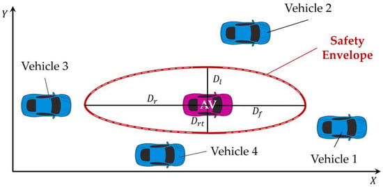
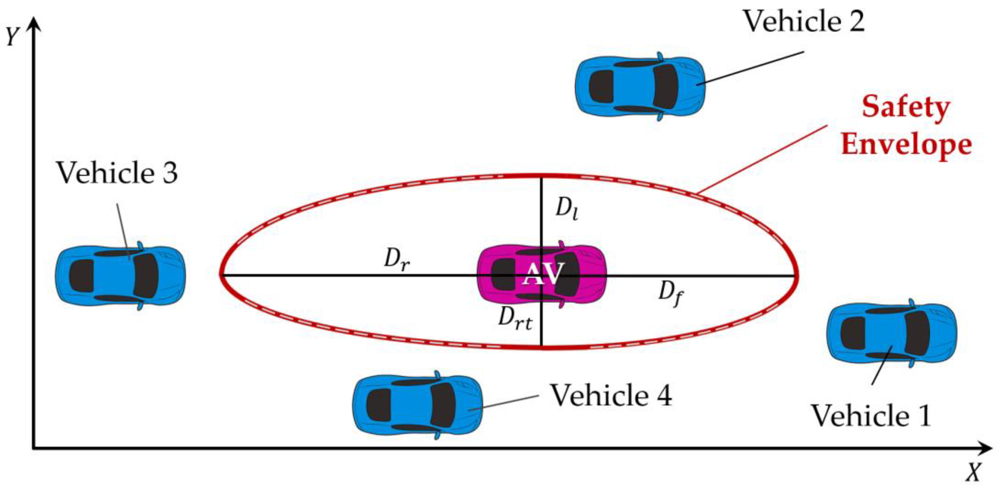
As illustrated in Figure 1, the safety envelope (red solid line) is geometrically represented as an oval-shaped region composed of four quarter ellipses (thin dashed curves), with its origin placed at the center of gravity of the AV. The major and minor axes of each ellipse are determined based on the safe distances () of the AV in the front () and on the left (), rear (), and right () directions. The safe distance () of the AV in each direction is considered the maximum of the individual safe distances between the AV and all surrounding vehicles in that direction as described in Equation (1). This approach ensures that the AV retains sufficient space with the surrounding vehicles to avoid collisions.
and are the longitudinal and lateral coordinates of a surrounding vehicle , respectively. and are the longitudinal and lateral coordinates of the AV, respectively. and respectively denote the longitudinal and lateral safe distance between the AV and the surrounding vehicle .
Figure 1.
Geometric definition of the safety envelope. The safety envelope of the AV is geometrically represented as an oval region composed of four quarter-ellipses centered at the AV’s center of gravity. The thin dashed curve indicates the quarter-ellipses used to form the envelope boundary.
The safety envelope is geometrically formed by four quarter ellipses, as described in Equation (2), and each of the quarter ellipses is determined by the safe distances , , , and . The major axis of each ellipse takes the safe distance in the longitudinal direction (either or ). The minor axis of each ellipse takes the safe distance in the lateral direction (either or ).
The safe distances are dynamically determined based on the real-time information of vehicles such as velocity, acceleration, and dimensions which are detailed explained in Section 2.2). The size of the safety envelope changes dynamically based on the safe distances.
In Mobileye’s approach, each surrounding vehicle is assessed to determine an appropriate response individually by the AV. In contrast, the proposed safety envelope considers all surrounding vehicles collectively by setting a global safety region around the AV. It enables the AV to assess its safety holistically rather than via multiple pairwise interactions; thus, the AV can deal with complex traffic environments efficiently. The ADS’ dynamic process of generating the safety envelope and the collision avoidance strategy controlling the AV to sustain its safety envelope repeats every 0.01 s. As a result, the ADS can rapidly respond to changes in the traffic environment and ensure the safety of both the AV and its surrounding vehicles.
2.2. Modified Longitudinal and Lateral Safe Distances
The longitudinal safe distance proposed by Mobileye [7] may result in overconservative driving behavior, as the worst-case scenarios may rarely happen in real driving situations. To balance practicality and safety, the actual acceleration of the rear vehicle is considered instead of its maximum acceleration, and the length of vehicles is accounted.
and shown in Figure 1 are considered the modified longitudinal safe distance, as described in Equation (3). The longitudinal safe distance is the distance traveled by the rear vehicle during the response time at its current acceleration, plus its braking distance under a reasonable minimum deceleration and including the lengths of both the vehicles, and minus the braking distance of the front vehicle under maximum deceleration.
where and denote the longitudinal velocities of the rear and front vehicles, respectively. is the driver’s response time of the rear vehicle, is the minimum reasonable deceleration in the longitudinal direction of the rear vehicle, is the maximum longitudinal deceleration of the front vehicle, and is the longitudinal acceleration of the rear vehicle. is the length of both the vehicles.
When no vehicle is detected ahead of the AV, , and are considered 0. In this case, the longitudinal safe distance of the AV is the distance it drives during the response time at its current acceleration and including its braking distance under a reasonable minimum deceleration as well as the length of the vehicles. When no vehicle is detected behind the AV, is considered the maximum velocity limitation. This ensures that the AV or the rear vehicle can execute a complete stop to avoid collisions with suddenly appearing obstacles or vehicles in the longitudinal direction.
Similarly, the lateral safe distance is modified by replacing the maximum accelerations of the left and right vehicles with their actual values and including the vehicle widths. and shown in Figure 1 use the modified lateral safe distance, as described in Equation (4). The vehicles on the left and right drive the lateral distance toward each other during the response time with their current accelerations and considering their brake distance with a reasonable minimum deceleration as well as their widths.
and denote the lateral velocities of the vehicles on the left and right, respectively, and and denote their corresponding response times, respectively. is the minimum reasonable deceleration in the lateral direction of the vehicle that is likely to be used by a human driver when recognizing a vehicle driving toward itself. and denote the real lateral acceleration of the left and right vehicle, respectively, and is the width of the vehicles.
In situations wherein no vehicles are present to the right or left of the AV, , , , or are considered 0. In this case, the lateral safe distance of the AV is the distance it drives during the response time with its current acceleration, plus its braking distance with reasonable minimum deceleration, and plus the width of both the vehicles. This ensures that the AV can safely come to a stop for avoiding lateral collisions when a sudden obstacle or vehicle appears from the lateral direction. The modifications are comparatively evaluated in Section 4.5.
3. Collision Avoidance Strategy and Lane-Changing Method
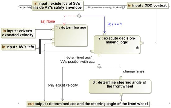
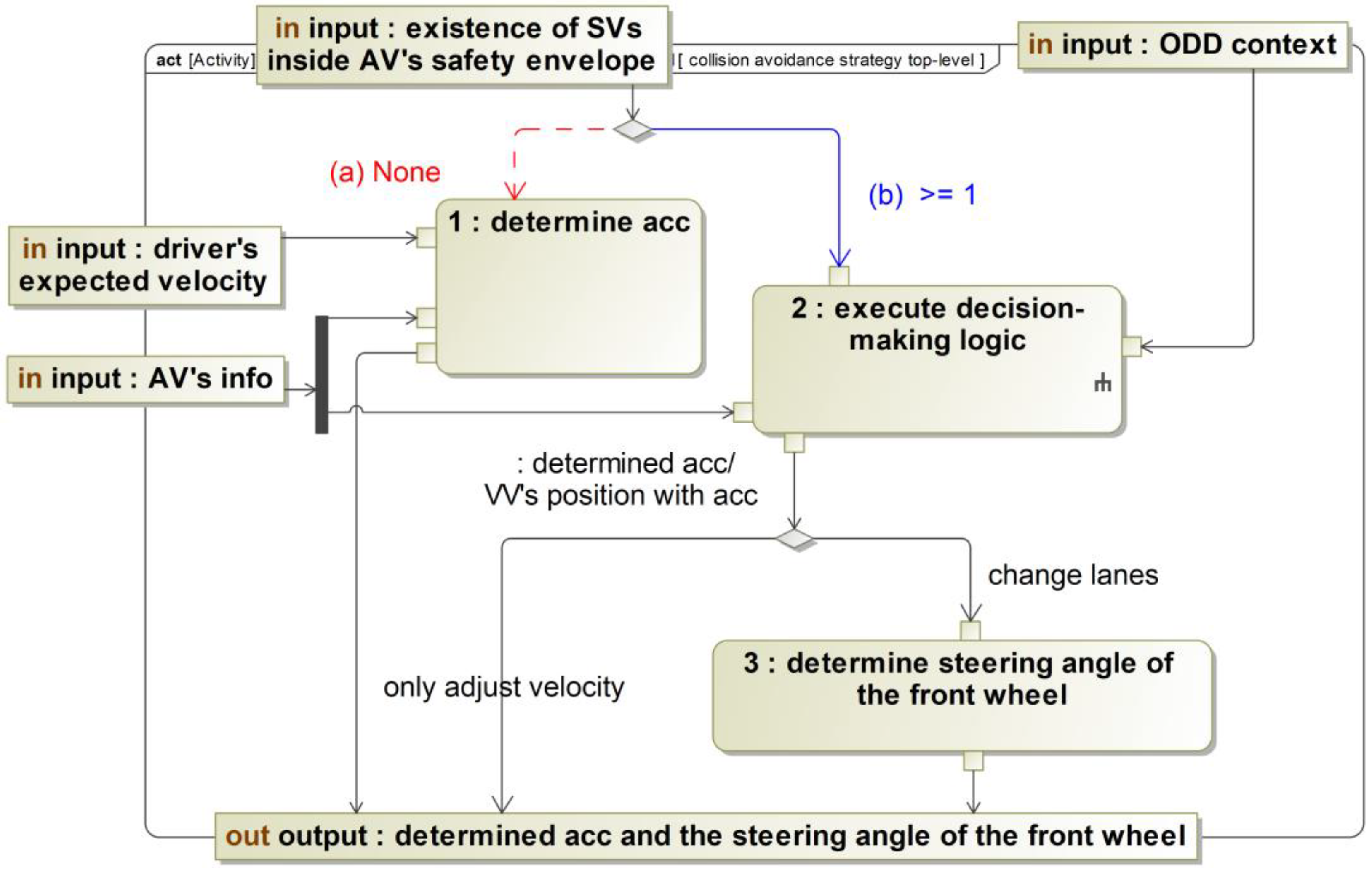
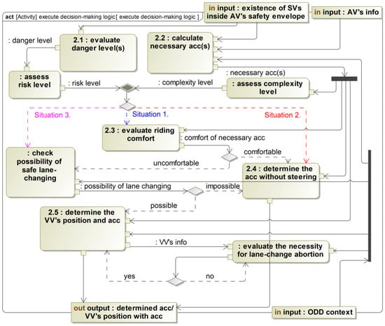
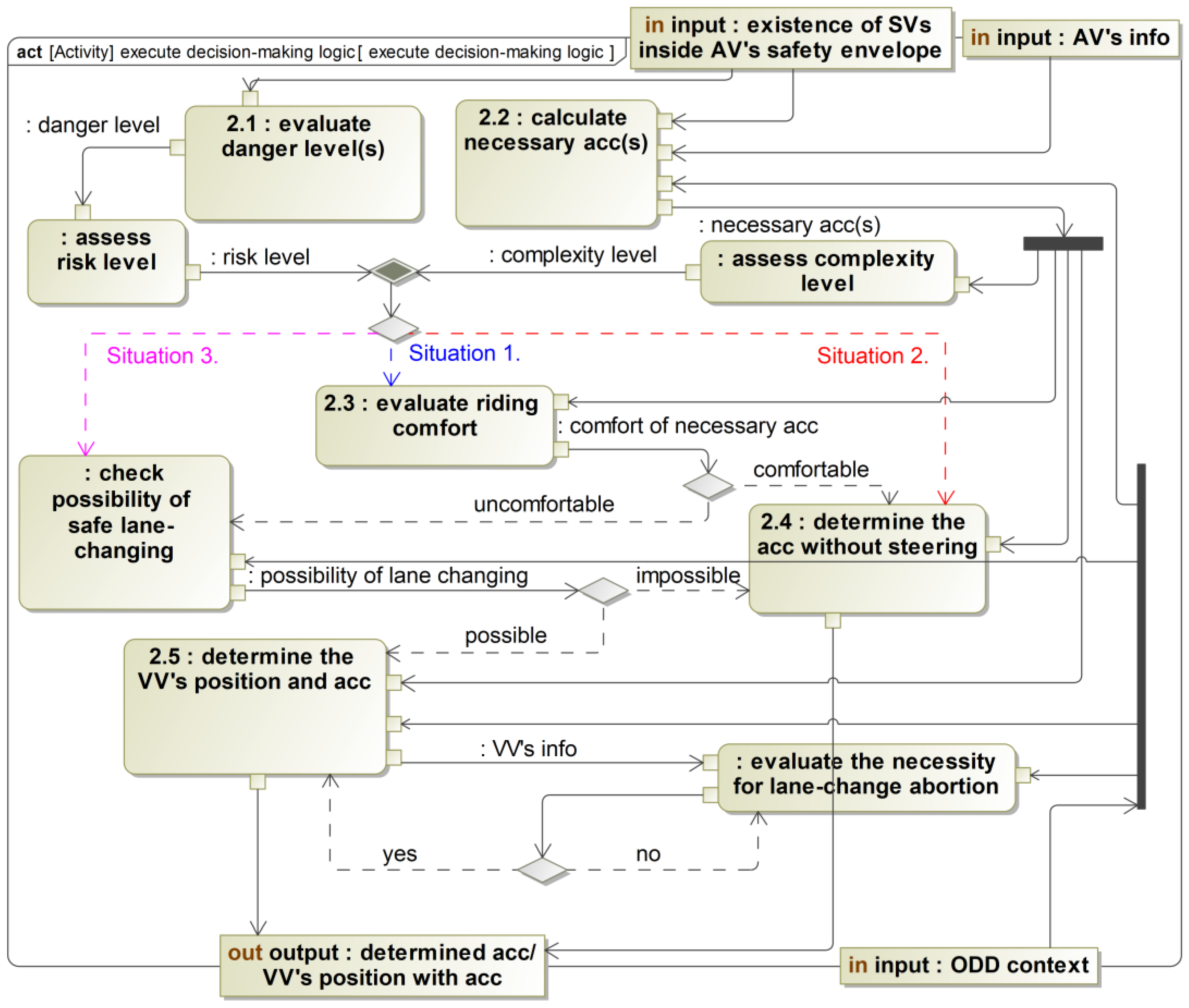
As defined in Section 2, the safety envelope is a dynamic boundary that distinguishes between safe and unsafe conditions for an AV. A collision avoidance strategy is proposed to sustain this envelope even under hazardous situations. This enables the AV to ensure safety by dynamically adjusting its velocity or changing lanes with velocity adjusting. System modeling language (SysML) is a general graphical modeling language that enables describing system models from the perspective of structure, behavior, parameters, and requirements [20,21]. As shown in Figure 2 and Figure 3, the proposed collision avoidance strategy is described using SysML activity diagrams (CATIA Magic Systems of Systems Architect 2024x Refresh2), which can provide a visual and comprehensive understanding of the entire process. Figure 2 and Figure 3 are presented in a simplified form to improve readability by reducing the amount of text in the figures. Long descriptions in the actions are replaced with numbered concise labels, and annotations of control flows are shortened to keywords. The full descriptions of the numbered actions are provided in Table 1, and the full definitions of the shortened annotations of control flows are summarized in Table 2. Abbreviations used in the figures include acc (acceleration), VV (virtual vehicle) and SV (surrounding vehicle).
Figure 2.
Collision avoidance strategy top level: activity diagram for condition recognition. The full descriptions of the numbered actions are provided in Table 1, and the full definitions of the shortened annotations of control flows are summarized in Table 2. Abbreviations: acc (acceleration), VV (virtual vehicle) and SV (surrounding vehicle). The small symbol attached to the action “execute decision-making logic to avoid potential collision” indicates that its internal behavior is further detailed in a lower-level SysML activity diagram (Figure 3).
Figure 3.
Collision avoidance strategy detail: activity diagram for executing decision-making logic. The full descriptions of the numbered actions are provided in Table 1, and the full definitions of the shortened annotations of control flows are summarized in Table 2. Abbreviations: acc (acceleration), VV (virtual vehicle) and SV (surrounding vehicle).
3.1. Collision Avoidance Strategy
3.1.1. Condition Recognition
As described in Section 2, the safety envelope is formed using the acceleration, velocity, and position of the AV and its surrounding vehicles. Based on the safety envelope and the positions of the surrounding vehicles, the existence of surrounding vehicles within the safety envelope is analyzed. The collision avoidance strategy outputs the acceleration and front wheel steering angle of the AV based on inputs such as the position, velocity, acceleration, and steering angle of the AV; operational design domain (ODD) context; and existence of surrounding vehicles within the safety envelope of the AV, as shown in Figure 2. The ODD context includes information about surrounding vehicles and the road (such as lane markers and boundaries), based on which the AV can identify its current lane. This process is important for restricting lane-changing directions of the AV: if the AV is already in the leftmost lane, it cannot change to the left; similarly, if it is in the rightmost lane, it cannot change to the right.
As the number of vehicles within the safety envelope of the AV directly affects the situation of the AV, two conditions are defined:
In condition (a), the ADS executes the action “determine acceleration to reach the driver’s expected velocity” since the AV is safe. The AV accelerates to meet the driver’s expected velocity. The acceleration is zero when the AV’s current velocity matches the driver’s expected velocity.
In condition (b), the ADS executes the action “execute decision-making logic to avoid potential collision” since the AV is in danger. The decision-making logic determines the AV to perform velocity adjusting or lane-changing with velocity adjusting to ensure no vehicles remain inside its safety envelope, thereby avoiding potential collisions. The detailed decision-making logic applied when one or more surrounding vehicles are detected inside the AV’s safety envelope is detailed in Figure 3 and Section 3.1.2.
If the decision-making logic determines that the AV to sustain its safety envelope by only adjusting its velocity, the determined acceleration is output. If the AV determines to change lanes, a virtual vehicle is generated on the target lane to guide the lane-changing, which is detailed in Section 3.2.1. The ADS executes the action “determine the steering angle of the front wheel using the PD controller to follow the virtual vehicle” and outputs the steering angle of the front wheel, which is introduced in Section 3.2.2.
3.1.2. Decision-Making Logic
When the AV’s safety envelope is intruded, an appropriate response is determined to sustain the safety envelope by executing the decision-making logic as shown in Figure 3. The decision-making logic is based on the combination of the risk level and complexity level assessment with the consideration of riding comfort of the AV’s occupants.
When the surrounding vehicles enter the safety envelope of the AV, the danger level of each vehicle inside the safety envelope is checked. The danger level is evaluated by simultaneously calculating and comparing the time to collision (TTC) and critical TTC (cTTC) between the AV and each surrounding vehicle inside the safety envelope. The TTC introduced by Hayward [22] was considered the time remaining until two vehicles would collide if they maintain the current velocity and trajectory. The critical TTC is the threshold value [23] that distinguishes between safe and unsafe situations. When the TTC of a surrounding vehicle exceeds the cTTC, the vehicle is classified to be in a low danger level; otherwise, the danger level is considered high. If all vehicles within the safety envelope have low danger levels, the overall risk level of the situation is categorized as low. In contrast, if one or more vehicles exhibit high danger levels, the risk level is classified as high. When there is only one vehicle inside the AV’s safety envelope, the risk level of the situation is equivalent to the danger level of the vehicle.
Simultaneously, the acceleration required to avoid potential collisions with each vehicle inside the safety envelope is calculated. When two vehicles have the same velocity (zero relative acceleration), they will not collide. Thus, the necessary acceleration is defined as the value at which the AV needs adjust its velocity to match the velocity of the vehicle within the cTTC. When two or more vehicles are inside the safety envelope of the AV, the necessary accelerations required by the AV to avoid collision with all vehicles are concurrently calculated to mitigate the collision risk. The complexity level of the situation is assessed based on the calculated necessary accelerations that indicate the difficulty in sustaining the safety envelope. The complexity level is considered low if the calculated necessary accelerations are all in the same direction, whereas the complexity level is considered high if the necessary accelerations have different directions. When only one vehicle is present inside the AV’s safety envelope, the complexity level is low.
The risk level integrates the danger levels of all surrounding vehicles in the AV’s safety envelope. The complexity level indicates the difficulty to sustain the AV’s safety envelope, and therefore, the difficulty of mitigating the collision risks involved in a situation. By combining the results of risk and complexity level assessments, three situations are categorized:
In Situation 1, as the risk and complexity levels are low, the riding comfort of the AV occupants during maneuver is considered. The comfort of the necessary acceleration is evaluated by comparing it with the comfortable acceleration range [24]. If all the necessary accelerations are within the comfortable range, the AV applies the necessary acceleration with the maximum absolute value. If any of the necessary accelerations exceed the comfort threshold, the possibility of safe lane-changing is checked to improve the riding comfort by generating a virtual vehicle. If the AV can change lanes safely, the position of the virtual vehicle and the acceleration for lane-changing are determined, which is introduced in Section 3.2. If it is impossible to change lanes safely, the AV performs the necessary acceleration with the maximum absolute value is the maximum.
In Situation 2, the low complexity level indicates that the AV can avoid potential collisions by adjusting the velocity without steering. Under high risk level situations, the strategy prioritizes ensuring the safety of vehicles rather than the riding comfort of the AV occupants. As a result, the AV employs the necessary acceleration with the maximum absolute value to sustain the safety envelope and avoids potential collisions.
In Situation 3, the high complexity level means the dangerous vehicles are located in different directions relative to the AV. By adjusting the velocity alone, the AV may collide with the vehicle in the direction opposite to the direction of the determined acceleration. Thus, lane-changing has higher priority over velocity adjustment without steering. The possibility of safe lane-changing is checked from the perspective of safety. If safe lane-changing is impossible, the AV primarily avoids the vehicle in front whose danger level is highest by accelerating. If safe lane-changing is possible, the AV changes lanes with the acceleration by the guidance of the virtual vehicle, which is introduced in Section 3.2.1.
Once the lane-changing starts in Situations 1 and 3, a virtual vehicle is generated on the target lane as the lane-changing destination along with a safety envelope for the virtual vehicle. This safety envelope for the virtual vehicle is defined the same as the safety envelope for the AV. During lane-changing, the necessity for lane change abortion is determined by monitoring the intrusions in the safety envelope of the virtual vehicle. Once this safety envelope of the virtual vehicle is intruded, the risk and complexity levels are evaluated the same as the aforementioned method. If either the risk level or the complexity level is high, the AV needs to abort the lane-changing process and revert to the original lane. The AV reverts to the original lane by generating a new virtual vehicle on the original lane and applies the determined acceleration.
The collision avoidance strategy leverages the real-time safety envelope and risk and complexity level assessments to enable the ADS to make prompt and appropriate decisions. This involves adjusting the velocity without steering or lane-changing with velocity adjusting to sustain its safety envelope and avoid potential collisions.
3.2. Lane-Changing Method
3.2.1. Determining the Position of Virtual Vehicle and Lane-Changing Duration
In previous studies on lane-changing, a target lane-changing destination was determined, and a reference trajectory was generated using polynomial models. The AV then followed the reference trajectory using a PID controller. However, human drivers do not generate a reference trajectory but determine the target lane-changing destination and steer toward it based on their experience and visual inputs. To replicate this behavior, a virtual vehicle is generated at the target lane-changing destination, and the front wheel steering angle is determined using the PD controller to guide the AV steering toward the virtual vehicle on the target lane instead of planning a reference trajectory.
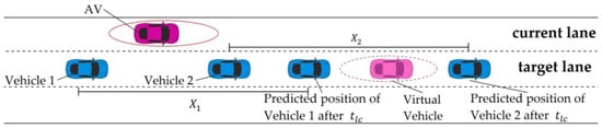
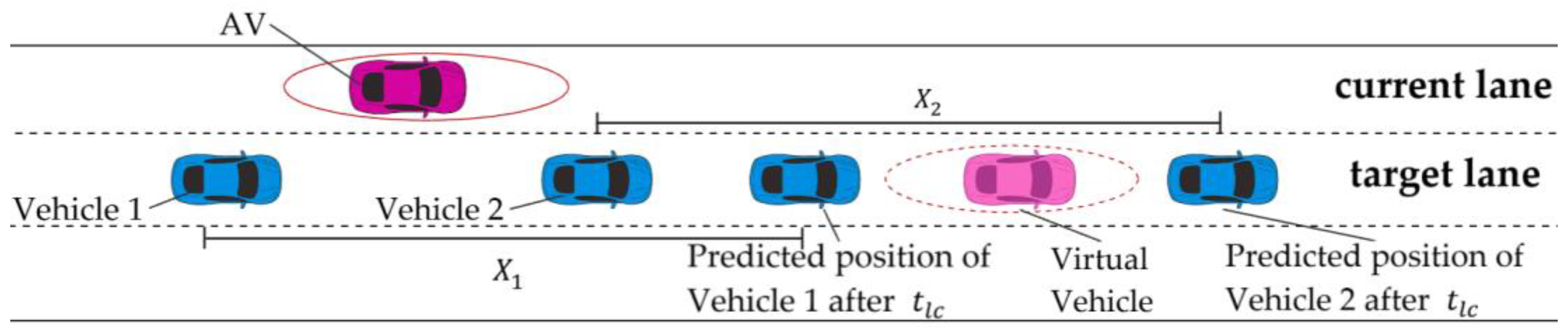
Figure 4 shows that when the AV determines to change lanes, a virtual vehicle (semi-transparent, magenta) is generated on the target lane-changing destination. The lateral position of this vehicle is at the center of the target lane, and its longitudinal position is determined by the lane-changing duration and the AV’s acceleration.
Figure 4.
Illustration of determining virtual vehicle’s position. The solid magenta oval outline around the AV represents the safety envelope of the AV, and the dashed magenta oval outline around the virtual vehicle represents the safety envelope of the virtual vehicle.
The lane-changing duration is determined based on the rear vehicle (vehicle 1 in blue color) and front vehicle (vehicle 2 in blue color) on the target lane. The longitudinal displacements and of vehicles 1 and 2, respectively, after the lane-changing duration are predicted based on the current velocities and acceleration, as shown in Equation (5).
To ensure safe lane-changing, neither vehicle 1 nor vehicle 2 after should intrude the safety envelope of the virtual vehicle. The lane-changing duration must satisfy the two longitudinal safe distance constraints in Equation (6). The constraints require the relative distances between the virtual vehicle with vehicle 1 and vehicle 2 after to be larger than the safe distances.
where
, and , denote the longitudinal position, velocity, and acceleration of vehicle 1, respectively. Similarly, , and denote the longitudinal position, velocity, and acceleration of vehicle 2, respectively. , , and denote the longitudinal position, velocity, and acceleration of the ego vehicle, respectively. denotes the predicted longitudinal position of the virtual vehicle, is the response time, is the minimum reasonable deceleration as introduced in 2.2, denotes the maximum longitudinal deceleration, and is the length of the vehicles.
and are calculated by solving the inequality constraints in Equation (6). If is less than 3 s, the AV cannot change lanes to ensure its safety as a small lane-changing duration requires high lateral acceleration, which is dangerous. If is less than 3 s and is greater than 3 s, the lane-changing duration is set to 3 s. This is because and are estimated based on the current states of vehicles 1 and 2, and a shorter lane-changing duration helps to reduce the uncertainties associated with the future behaviors of these two vehicles. If is greater than 3 s, the lane-changing duration is considered . After the lane-changing duration is determined, the position of the virtual vehicle is determined.
3.2.2. Lane-Changing Control Using a PD Controller
For smooth lane-changing maneuvers based on the virtual vehicle, the AV uses a PD-based steering controller to reach the position of the virtual vehicle. This controller minimizes the deviation between the AV and the virtual vehicle by adjusting the AV’s steering angle. The PID controller is a classical feedback control algorithm widely used in vehicle steering and trajectory tracking tasks because it is simple and effective [25]. The general equation of PID controller is described in Equation (7).
where is the control output at time , is the error signal at time , is the proportional gain, is the integral gain, and is the derivative gain. The integral term was neglected by setting to effectively obtain a PD controller:
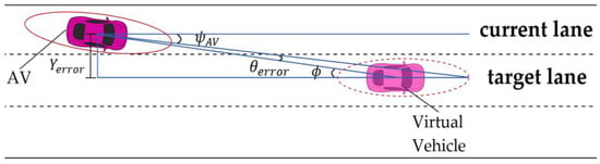
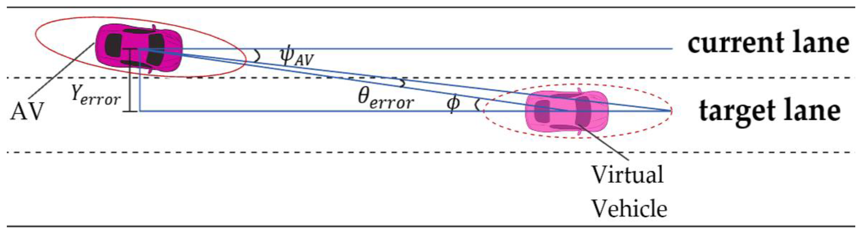
where is the desired steering angle at time and is the tracking error. The tracking error combines the lateral error and heading angle difference . As shown in Figure 5, the lateral error is the relative distance between the AV and virtual vehicle along the lateral direction. The heading angle difference is the angular difference between the current orientation of the AV and its direction toward the virtual vehicle as described in Equation (9).
Figure 5.
Illustration of tracking errors. The solid magenta oval outline around the AV represents the safety envelope of the AV, and the dashed magenta oval outline around the virtual vehicle represents the safety envelope of the virtual vehicle.
The two errors are combined to form a unified tracking error:
As the two components of tracking error are measured in different units (meters and radians), scalar weights 0.8 and 1.8 are employed to balance the contribution of the errors to the control signal. These values were selected heuristically to determine the relative physical impact of each error term on the vehicle’s control behavior. As heading deviations often lead to more severe instability during lane changes compared with small lateral offsets, a larger weight was assigned to the heading error to enhance its influence on the combined error metric although its unit (radian) is typically numerically smaller than that of the lateral error (meter).
Similarly, the proportional and derivative gains of the controller were determined empirically via simulations. The evaluation of controller’s response across multiple lane-changing cases revealed that = 0.02 and = 0.1 offered a well-balanced trade-off between tracking accuracy, steering smoothness, and ride comfort. The chosen values yielded a low tracking error without inducing oscillation or overshoot and were suitable for real-time implementation.
4. Verification of the Collision Avoidance Strategy Using the Safety Envelope for the ADS
4.1. Highway Operation Scenario and Vehicle Dynamic Model
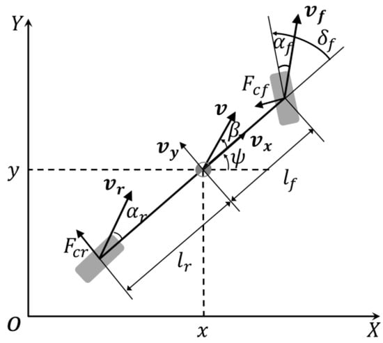
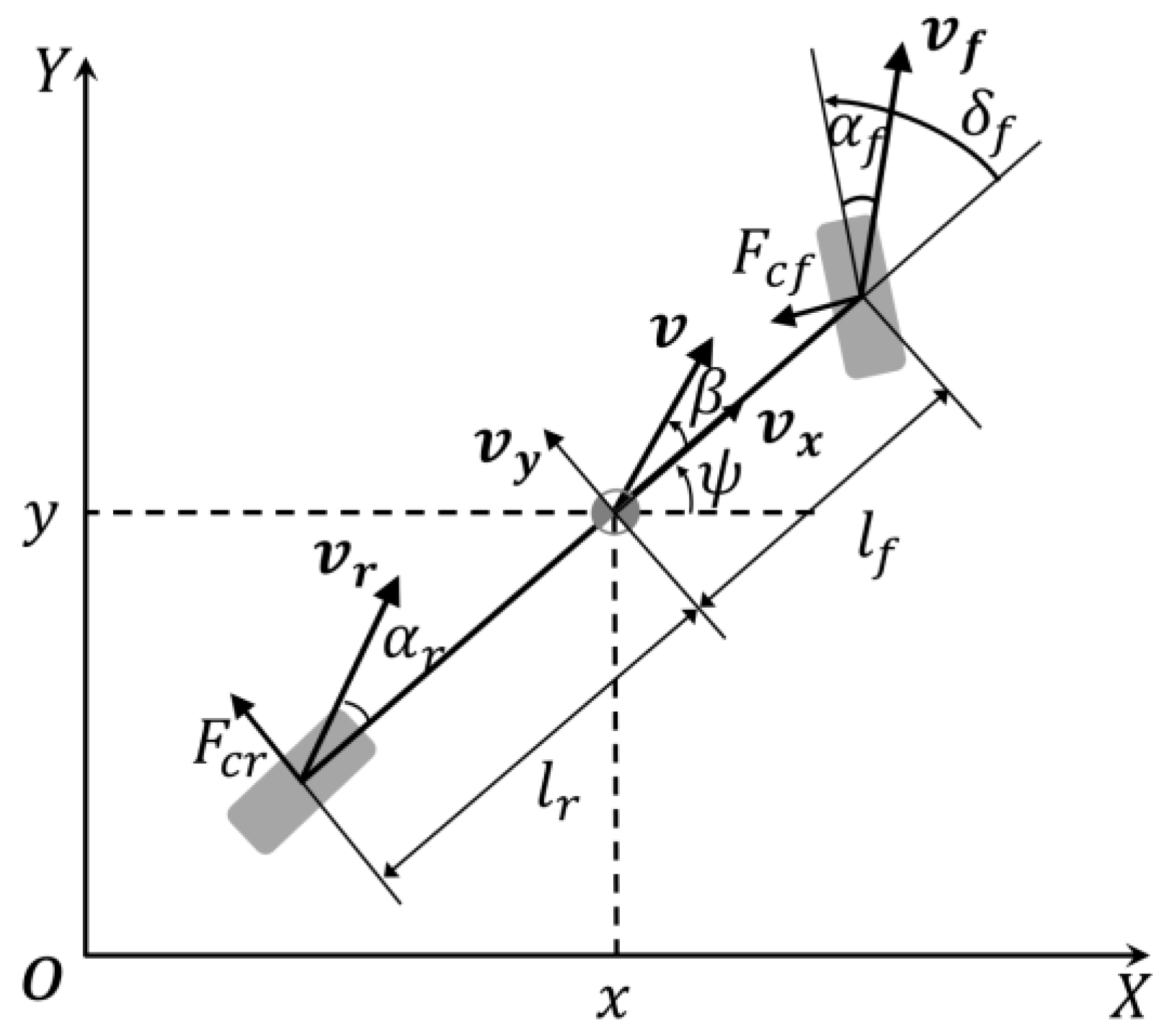
In this paper, the operational conditions of the AV were considered on highways that are characterized by high velocities and unidirectional traffic flows. The dynamic bicycle model was employed as the vehicle model, as shown in Figure 6. This model simplified the vehicle’s motion by representing the four actual wheels with two virtual wheels (front and rear) [26]. The vehicles in the simulation were assumed to be driven by front wheels, and the rear wheel angle was consistently set to zero. This dynamic bicycle model is expressed in Equation (11) [27,28].
are the longitudinal and lateral coordinates of the vehicle’s center of gravity (c.g.) in an inertial frame , respectively. and respectively denote the vehicle’s velocity and longitudinal acceleration. is the orientation of the vehicle, and is the slip angle. denotes the angle of the vehicle’s front wheel. and denote the longitudinal and lateral velocities in the body frame, respectively. is yaw rate of the vehicle. and are the lateral tire forces at the front and rear wheels, respectively. and are the slip angles of the front and rear wheels, respectively. Table 3 lists the definitions and values of , , , , , and . and are the control inputs for the motion of the AV, which are determined using the collision avoidance strategy that employs the safety envelope.
Figure 6.
Dynamic bicycle model.
Table 3.
Definitions and values of parameters used in the dynamic bicycle model.
4.2. Sensor Specification
For robust and comprehensive environmental perception, AVs are equipped with a multimodal sensor suite, including LiDAR, cameras, and radars with different detection ranges [29]. Herein, a sensor configuration comprising a 360-degree rotating LiDAR mounted at the center of the roof was employed. This sensor provided full-surround 3D point cloud data with a range of up to 200 m. A long-range radar installed at the front bumper enhanced forward object tracking, whereas medium-range radars positioned at the rear corners monitored the lateral-rear vehicles within an 80 m range. In addition, six short-range radars covered all close-range zones within 20 m.
Cameras were installed to perform semantic perception tasks. A main forward camera and a wide-angle forward camera were mounted on the upper center of the windshield and front bumper, respectively, for long-range detection and wide field-of-view coverage up to 200 and 50 m, respectively. Side cameras that were positioned on both doors near the mid-front or mid-rear areas provided lateral monitoring up to 50 m. Based on a previous study [30], the combined sensor architecture, as summarized in Table 4, enabled the AV to detect short-, medium-, and long-range targets in all directions.
Table 4.
Directional perception coverage enabled by the sensor suite.
4.3. Simulation Assumptions
The proposed collision avoidance strategy by utilizing safety envelope for ADS under hazardous situations was verified via a simulation in MATLAB R2023b. Simulation functions were implemented in MATLAB to execute actions described in the activity diagrams shown in Figure 2 and Figure 3. The simulation scenario comprised an AV (ego vehicle) and six human-driven vehicles (HDVs). The sizes of the AV and surrounding vehicles were assumed to be 4.92 m × 1.86 m. All seven vehicles drove forward on a three-lane highway, with a width of 3.6 m. The simulation time step was 0.01 s. The simulated hazardous scenario featured multiple surrounding vehicles approaching from various directions. Some surrounding vehicles performed aggressive maneuvers, such as sudden acceleration and deceleration. Sudden cut-ins by these vehicles were also considered aggressive driving, we have shown simulation results that contain the sudden cut-ins scenario [20], simulation results for hazardous situations only contain sudden acceleration and deceleration are discussed herein. The initial conditions of vehicles are as follows:
AV: Driving in the middle lane with an initial velocity of 23 m/s. The expected driving velocity is 30 m/s.
HDV 1: Driving in the left lane with an initial velocity of 16 m/s and then sharply decelerates to interfere with the AV.
HDV 2: Driving in the left lane with an initial velocity of 18 m/s and sharply accelerating to interfere with the AV.
HDV 3: Driving in the middle lane behind the AV with an initial velocity of 23.5 m/s and accelerating.
HDV 4: Driving in the middle lane ahead of the AV with an initial velocity of 22 m/s and then sharply decelerates and drives aggressively toward the AV.
HDV 5: Driving in the right lane with an initial velocity of 32 m/s and then accelerating.
HDV 6: Driving in the right lane with an initial velocity of 32 m/s.
In this simulation, four surrounding vehicles (HDV 1, HDV 2, HDV 3, and HDV 4) were designed to perform aggressive driving to against the AV and two surrounding vehicles (HDV 5 and HDV 6) were designed to drive with high velocities. In this way, the simulation created hazardous scenarios for verifying the proposed collision avoidance strategy.
4.4. Simulation Results
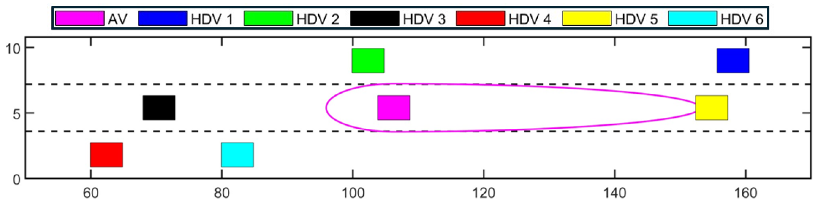
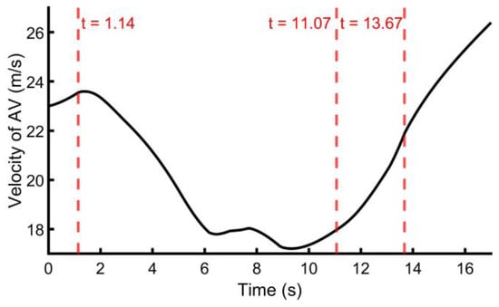
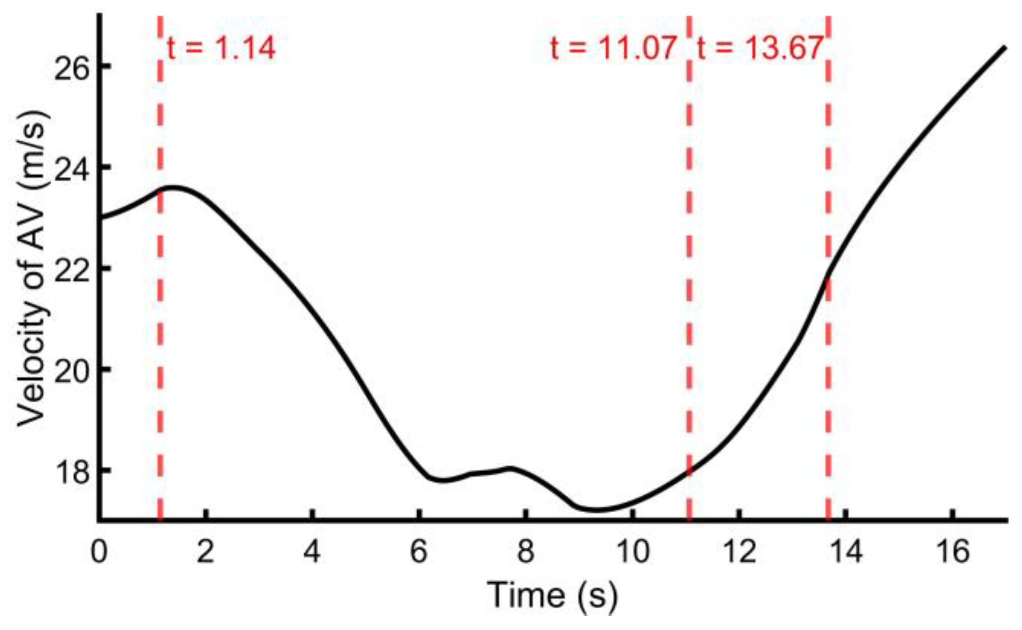
Figure 7, Figure 8, Figure 9, Figure 10, Figure 11, Figure 12 and Figure 13 show the simulation results for the assumed conditions over a period of 17 s. From 0.01 to 1.13 s, the AV remains safe as the number of vehicles inside its safety envelope is 0; this corresponds to condition (a) in the proposed strategy. The current velocity of the AV is lower than the expected velocity of 30 m/s; thus, it accelerates to meet the expected velocity. However, at 1.14 s, HDV 5 (yellow vehicle) suddenly applies sharp brakes and drives aggressively against the AV (magenta vehicle). It thus enters the safety envelope of the AV from the front, as shown in Figure 7. As HDV 5 (yellow vehicle) has a high danger level and is the only vehicle inside the AV’s safety envelope, this situation is considered to have a high risk level and low complexity level and corresponds to Situation 2 of the collision avoidance strategy. Consequently, the AV decelerates immediately to avoid potential collision with HDV 5 (yellow vehicle) without considering riding comfort, as shown in Figure 8.
Figure 7.
Positions of the AV within its safety envelope and surrounding vehicles after 1.14 s. Each colored rectangle represents the AV and HDVs. The solid magenta oval outline around the AV denotes its safety envelope. The black dashed lines represent the lane boundaries.
Figure 8.
Time history of AV’s velocity.
Figure 9.
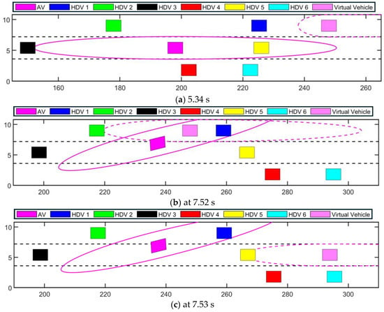
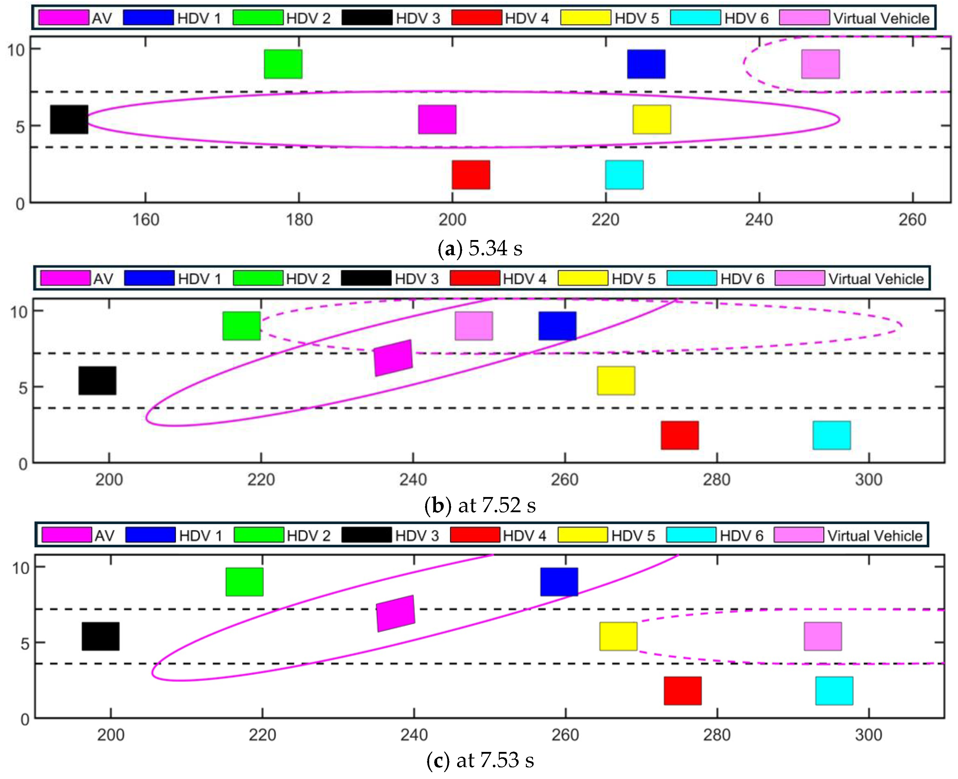
Positions of the virtual vehicle and AV within the safety envelope and surrounding vehicles at 5.34 s (a), 7.52 s (b), 7.53 s (c). Each colored rectangle represents the AV, virtual vehicle, and HDVs. The solid magenta oval outline around the AV represents the safety envelope of the AV, and the dashed magenta oval outline around the virtual vehicle represents the safety envelope of the virtual vehicle. The black dashed lines represent the lane boundaries.
Figure 10.
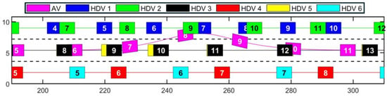
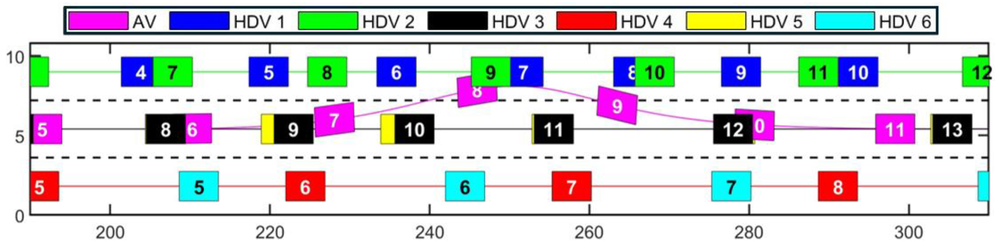
Trajectory of the AV changing to the left lane and reverting to the middle lane, and the trajectories of surrounding vehicles from 180 to 300 m. Each colored rectangle represents the AV and HDVs, and the numbers in the rectangle denote the simulation time step in seconds. The x-axis is scaled twice as much as the y-axis, where the visualized size of the vehicles is changed accordingly. The black dashed lines represent the lane boundaries.
Figure 11.
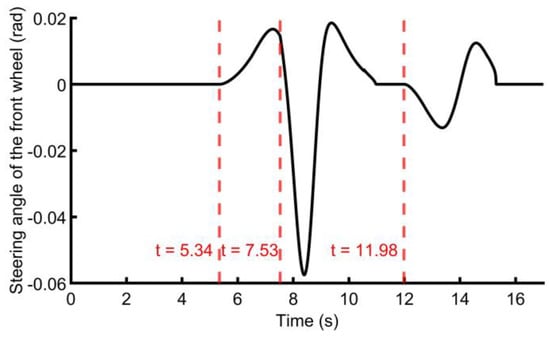
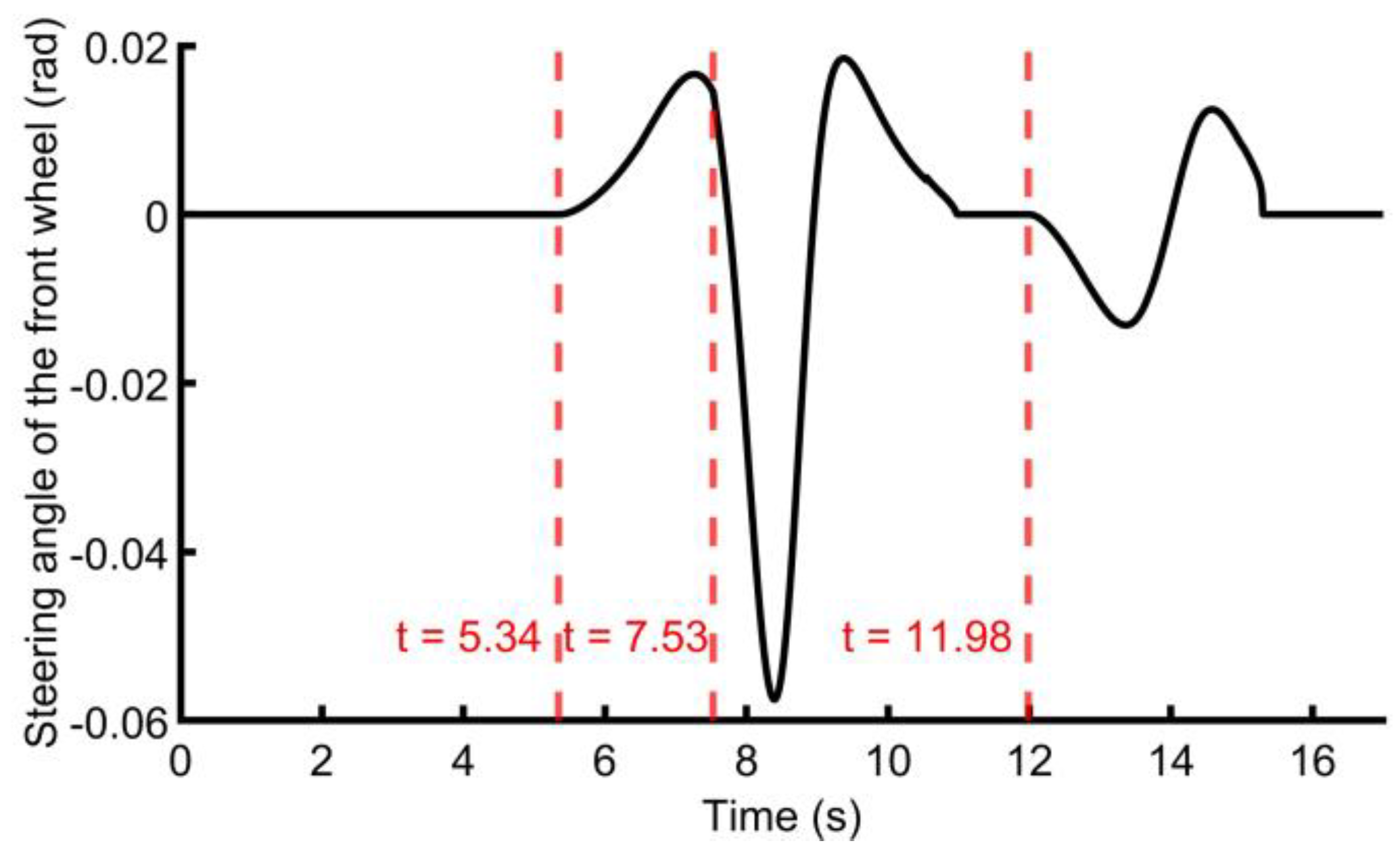
Steering angle of the AV’s front wheel.
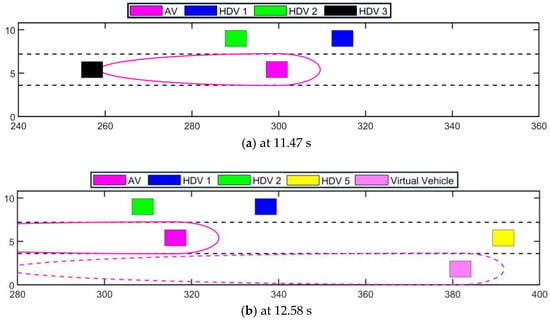
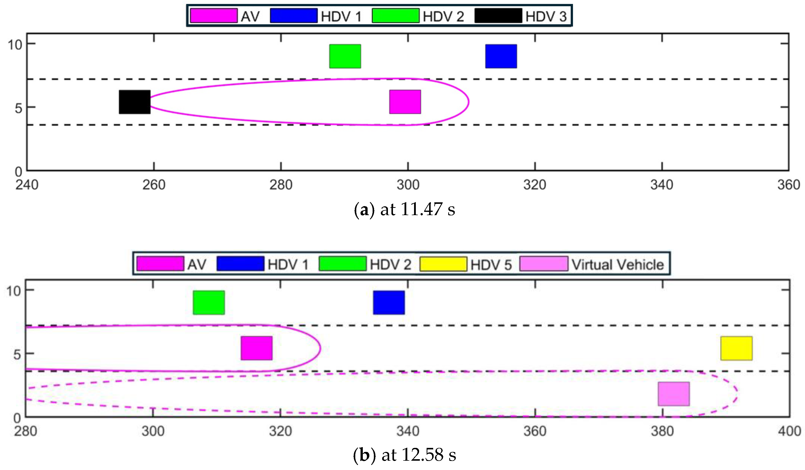
Figure 12.
Positions of the virtual vehicle and AV with their safety envelope and surrounding vehicles at 11.47 s (a) and 12.58 s (b). Each colored rectangle represents the AV, virtual vehicle, and HDVs. The solid magenta oval outline around the AV represents the safety envelope of the AV, and the dashed magenta oval outline around the virtual vehicle represents the safety envelope of the virtual vehicle. The black dashed lines represent the lane boundaries.
Figure 13.
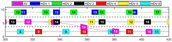
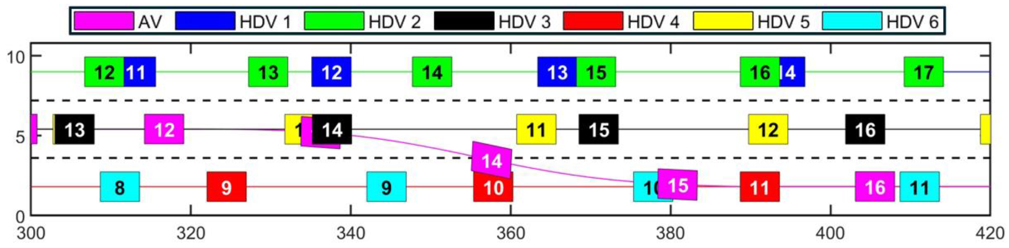
Trajectory of the AV changing to the right lane and the trajectories of surrounding vehicles from 320 to 440 m. Each colored rectangle represents the AV and HDVs, and the numbers in the rectangle denote the simulation time step in seconds. The x-axis is scaled twice as much as the y-axis, where the visualized size of the vehicles is changed accordingly. The black dashed lines represent the lane boundaries.
During the deceleration of the AV, at 5.34 s, HDV 3 (black vehicle) accelerates and enters into the safety envelope of AV from behind, as shown in Figure 9a. In this situation, the two vehicles in the AV’s safety envelope travel in opposite directions and have low danger levels. This situation corresponds to Situation 3 of the collision avoidance strategy, with low risk level and high complexity level. A virtual vehicle (semi-transparent magenta vehicle) is generated on the left lane to check the possibility of safe lane-changing as Figure 9a shows. Since safe lane-changing is possible, the AV shifts from the middle lane to the left lane guided by the virtual vehicle to avoid potential collisions. At 7.52 s, HDV 1 (blue vehicle) and HDV 2 (green vehicle) decelerate and accelerate, respectively, to interrupt AV’s lane-changing task. HDV 1 (blue vehicle) and HDV 2 (green vehicle) ultimately enter the safety envelope of the virtual vehicle from different directions as shown in Figure 9b. Based on the collision avoidance strategy introduced in session 3.1.2, the AV needs to abort the lane- changing and return to its original lane. A new virtual vehicle (semi-transparent magenta vehicle) is generated in the middle lane as described in Figure 9c to guide the AV to the middle lane by applying deceleration as shown in Figure 8. Figure 10 shows the trajectory of the AV changing to the left lane and reverting to the middle lane and the trajectories of surrounding vehicles. The front wheel steering angle of the AV is shown in Figure 11.
After the AV successfully changes lanes, it continues to drive in the middle lane again. As the AV’s safety envelope does not contain any intruding vehicles, the AV accelerates to reach the expected velocity as shown in Figure 8. At 11.07 s, HDV 3 (black vehicle) sharply accelerates and enters the safety envelope of the AV from behind, as shown in Figure 12a. In this situation, HDV 3 has low danger level and is the only vehicle inside the AV’s safety envelope. Thus, both the risk and complexity levels of the situation are low, corresponding to Situation 1 of the proposed collision avoidance strategy, where the riding comfort is considered. As the riding comfort is satisfied, the AV accelerates to avoid potential collision, as shown in Figure 7. At 11.98 s, HDV 3 (black vehicle) continues to accelerate, causing the necessary acceleration for the AV to avoid collision extending the riding comfort range. Consequently, a virtual vehicle (semi-transparent magenta vehicle) is placed on the right lane to determine the possibility of safe lane-changing as shown in Figure 12b.
As lane-changing can be performed safely, the AV accelerates to change from the middle lane to the right lane as shown in Figure 8, Figure 11 and Figure 13. During lane-changing at 13.67 s, no vehicles remain in the AV’s safety envelope and the AV accelerates until the lane change is complete and continues to accelerate thereafter, as shown in Figure 8.
These results indicate that the collision avoidance strategy enables the AV to respond dynamically and adaptively to hazardous situations in highway scenarios.
4.5. Comparative Simulations on Safe Distance Modifications
The safe distances proposed by Mobileye [7] can lead to overly conservative driving behavior because the assumed worst-case scenarios rarely occur in real traffic. To reduce conservatism, the safe distances are modified in this research by using the actual accelerations of surrounding vehicles instead of maximum values. In addition, vehicle body size is not accounted for in Mobileye’s formulation. For safety concerns, the length and width of vehicles are added to the safe distances to avoid collisions in near-limit interactions. These modifications are made to reduce conservatism while improving safety. The effectiveness of the two modifications is evaluated through two comparative simulations.
Three variants are considered in the following comparisons.
Baseline variant (V0): Original safe distances defined by Mobileye.
Acceleration modified variant (V1): The safe distances are modified by replacing the maximum acceleration assumption with the actual accelerations of surrounding vehicles.
Acceleration and size modified variant (V2): The vehicle body size is incorporated into the safe distances, and the maximum accelerations are replaced with the actual accelerations. These are the safe distances formulations used in this research.
4.5.1. Scenario A: Conservatism Reflected in Lane-Change Feasibility
Overly conservative safe distances can unnecessarily restrict maneuver permissiveness, causing an AV not able to perform an intended maneuver even when it would remain feasible under more realistic assumptions. This scenario illustrates such conservatism using a lane-change example. Specifically, the AV intends to immediately change to the left lane, while during the lane change, the front and rear vehicles in the target lane decelerate and accelerate, respectively, to interrupt the AV’s maneuver. In the proposed strategy, once lane changing is initiated, the necessity of lane-changing abortion is checked as described in Section 3.1.2.
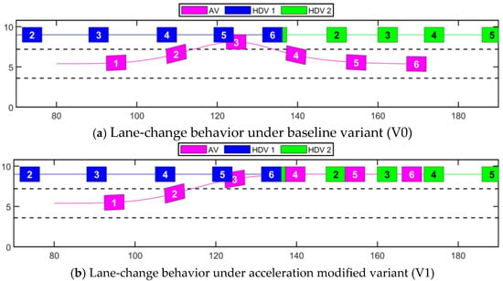
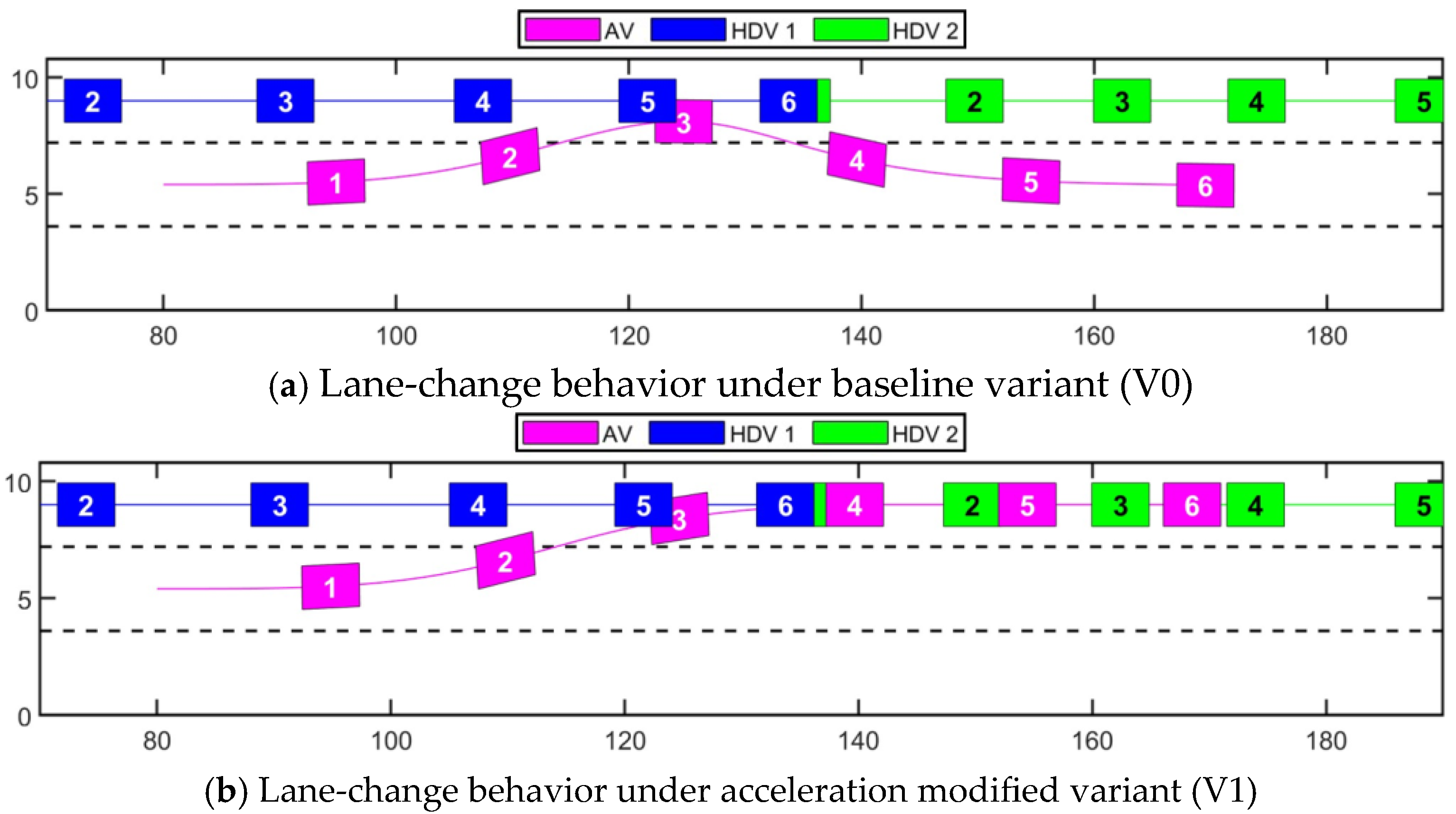
Figure 14 compares the lane-change behaviors for the baseline variant (V0), and the acceleration modified variant (V1) under the same initial condition. As shown in Figure 14a, under V0, the conservative safe distances trigger lane-changing abortion when HDV 1 accelerates and HDV 2 decelerates during the AV’s lane change. In contrast, as shown in Figure 14b, under V1, the AV maintains its safety envelope without triggering abortion and successfully completes the lane-changing. This comparison indicates that overly conservative safe distances assumptions can induce unnecessary maneuvers that make the AV unable to reach the intended target position. The simulation results show that the modified safe distances in V1 reduce conservatism compared with the original ones in V0.
Figure 14.
Comparison of lane-change behaviors for baseline variant (V0) and the acceleration modified variant (V1) under the same initial condition. The black dashed lines represent the lane boundaries.
4.5.2. Scenario B: Vehicle Size Effect in Near-Limit Scenarios
Scenario B evaluates the safety impact of vehicle size compensation in near-limit scenarios, where relative distances between vehicles become critical. Although safe distances in acceleration modified variant (V1) reduce conservatism, omitting the vehicle body size may underestimate collision risk in extreme cases. Therefore, safe distances in acceleration and size modified variant (V2) further incorporate vehicle length and width to reflect the physical size of the vehicle body. In the near-limit scenario, the vehicle in front of the AV suddenly brakes hard to a complete stop, requiring the AV to also perform to a full stop to avoid a rear-end collision.
Table 5 summarizes the results for Scenario B, including minimum relative distances between the AV and the surrounding vehicle, which are the distance between the two vehicle’s centers of gravity. Collisions are observed for V0 and V1, while V2 avoids collision. Although V0 and V1 exhibit a minimum relative distance of 1.04 m and 1.05 m, the collision occurred because the vehicle’s length is 4.92 m, which means an overlap occurred. Incorporating vehicle length in V2 increases the effective safety margin, resulting in a minimum relative distance of 5.43 m, which exceeds the vehicle length and therefore avoids overlapping and prevents collision in this near-limit case.
Table 5.
Safety outcomes in the near-limit interaction scenario (Scenario B).
4.5.3. Summary
The comparative results highlight two complementary effects of the safe distances modifications. Scenario A indicates that the baseline formulation can be conservative in lane-change maneuver, and that incorporating actual accelerations can reduce this conservatism and improve maneuver permissiveness. Scenario B indicates that vehicle size compensation is important for safety in near-limit interactions, where small center-to-center distances may still imply overlap. Overall, the safe distances formulations used in this research that combines acceleration and vehicle size modification can reduce conservatism and improve safety.
4.6. Discussion
The proposed collision avoidance strategy utilizing the safety envelope for ADS was verified in terms of AV safety in hazardous situation cases as shown in Section 4.4. During simulation, a dynamic bicycle model was used to represent vehicle dynamics that captured longitudinal–lateral coupling while linearizing tire behavior and omitting nonlinear effects, as shown in Equation (11). The dynamic bicycle model is generally appropriate for maneuvers with moderate lateral acceleration and small slip angles, for which the linearized tire assumption is reasonable. In the simulation conducted in this study, the maximum lateral acceleration was 0.23 g, and the maximum slip angle was 0.035 rad, the dynamic bicycle model therefore provided a suitable representation for verifying the proposed collision avoidance strategy. In future work, the verification will be extended to more hazardous scenarios by applying more advanced vehicle models. The scenarios will include cases where the AV performs maneuvers with high lateral acceleration and large slip angles under different road surface conditions, and high-fidelity tire models and multi-degree-of-freedom vehicle dynamics will be applied accordingly.
The safe distances in this paper were adapted from Mobileye’s formulation [7], which can lead to conservative driving. To reduce conservatism, actual accelerations of surrounding vehicles were used instead of the maximum values as shown in Equations (3) and (4) to shorten the safe distances and make the strategy less conservative, as demonstrated in Section 4.5.1. The accelerations of the surrounding vehicles in Equations (3) and (4) were determined using the dynamic bicycle model. In practice, these accelerations are estimated from the velocities of surrounding vehicles detected by sensors. As such estimations can involve temporal delays and estimation noise, a state observer (e.g., Kalman filter) must be used to estimate and denoise accelerations while accounting for latency. Note that such gaps can impact simulation results.
In this study, the safety envelope was constructed from longitudinal and lateral safe distances computed separately in each direction, providing a dynamic boundary for distinguishing the AV’s safe and unsafe situations through envelope intrusion. The simulation results showed that the envelope successfully distinguished the AV’s safe and unsafe situations and supported collision avoidance, even after reducing conservatism. To further improve dynamics consistency and better capture coupled longitudinal and lateral limits, future work will investigate formulations with stronger coupling, including friction circle constraints and reachability based and invariance based safety sets. In addition, for practical deployment, robustness of the safety envelope can be improved by incorporating behavioral uncertainty of surrounding vehicles and tire road friction limits into the safe distances, which are then reflected in the envelope construction and evaluation. Accordingly, future work will consider measures such as adding error margins to the safe distances, enforcing friction limited acceleration constraints, and incorporating uncertainty detection and behavior prediction for surrounding vehicles.
In the collision avoidance strategy proposed in this paper, when the safety envelope of the AV was intruded, a binary high/low assessment for both risk level and complexity level was introduced to clearly and quickly categorize the AV’s situation. The combination of the risk and complexity levels results in four possible combinations, which categorizes the situation into three types as introduced in Figure 3. For the scope of the present study, this provides a practical way to categorize situations. After the situation categorization, the decision-making logic performs a sequence of subsequent checks and evaluations to finally determine an appropriate response for the AV. As future work, continuous indicators as well as threshold and sensitivity analyses will be considered to assess the risk and complexity levels which may reduce the reliance on such downstream checks and evaluations.
For lane-changing, existing studies commonly generate a reference trajectory using polynomial models and integrate a PID controller with a lookahead model for the AV to follow the reference trajectory. The proposed lane-changing method does not require generating a reference trajectory. Instead, a virtual vehicle is generated to guide the AV’s maneuver. When a lane change must be aborted and the AV needs to return to the original lane, trajectory based methods typically regenerate a return trajectory and apply a tracking algorithm to follow it, whereas lane changing abortion in the proposed method is achieved by relocating the virtual vehicle to the original lane. The lane-changing and lane-changing abortion of the AV are achieved by integrating a PD controller to guide the AV’s steering toward the virtual vehicle. In the PD controller, the tracking error combines the lateral error and heading angle difference between the AV and the virtual vehicle as shown in Figure 5. A fixed gain set ( = 0.02 and = 0.1), used in Equation (8), enables the AV to successfully achieve lane-changing behavior guided by the virtual vehicle; however, this behavior may require further tuning for different driving conditions. Compared with lane-changing trajectories generated using the polynomial models, the trajectory of the AV guided by the virtual vehicle exhibits higher curvature in the middle segment. In future, differences between the trajectories generated by the lane-changing method and polynomial models will be analyzed and the causes for such differences will be determined (e.g., virtual vehicle’s initial position and PD controller gains). Based on the findings, the proposed lane-changing method will be improved accordingly.
5. Conclusions
ADS is considered an effective solution to reduce traffic accidents caused by human errors. However, in hazardous and complex traffic situations where an AV dynamically interacts with multiple surrounding vehicles, including aggressive maneuvers by some vehicles, the AV still faces the challenge of promptly distinguishing safe/unsafe situations and determining appropriate responses to prevent potential collisions.
To address this challenge, this paper proposed a collision avoidance strategy utilizing safety envelope for ADS. The safety envelope was defined based on longitudinal and lateral safe distances adapted from Mobileye’s formulation, allowing an AV to distinguish between safe and unsafe situations through envelope intrusion detection. When the AV is in an unsafe situation, the risk and complexity levels of the situation are assessed and combined to categorize the situation into three types. Based on the situation type, the decision-making logic then performs subsequent checks and evaluation to determine an appropriate maneuver for the AV, which contains adjusting velocity or lane-changing with velocity adjusting. In addition, a novel lane-changing method was proposed without generating a reference trajectory. In the method, a virtual vehicle was introduced along the preceding path in the target lane, and a PD controller guided the AV’s steering toward the virtual vehicle, enabling safe lane-changing and lane-changing abortion when necessary.
The collision avoidance strategy was verified using MATLAB via a highway traffic simulation involving hazardous situations with multiple surrounding vehicles in various directions performing aggressive driving behavior. Results showed that, for all three situation types, the ADS followed the intended strategy, secured the safety envelope and avoided collision. Based on the simulation results, two main findings are obtained. First, categorizing the AV’s situations by combining the risk level and complexity level provides a structured and systematic way to handle complex interactions between the AV and multiple surrounding vehicles. Rather than relying on case by case handling, it provides a more unified and reliable basis for response determination. Second, the comparative study indicates that modified safe distances can reduce conservatism by using the actual accelerations of surrounding vehicles instead of maximum values, and improve safety by accounting vehicles’ body size, thereby balancing conservatism and safety for AV’s maneuvering.
This paper mainly focused on verifying the proposed collision avoidance strategy on highway traffic scenarios, with characteries of high velocity and unidirectional traffic flows. In future research, the proposed strategy will be extended and verified on curved roads and urban intersections, with more complex traffic environments. The traffic participants of the AV will be extended to static obstacles, pedestrians, and surrounding AVs. The effectiveness and generalizability of the collision avoidance strategy that uses the safety envelope will be further evaluated.
Author Contributions
Conceptualization, M.G. and H.N.; methodology, M.G. and H.N.; software, M.G.; validation, M.G. and H.N.; formal analysis, M.G.; investigation, M.G.; resources, MG.; data curation, M.G.; writing—original draft preparation, M.G.; writing—review and editing, M.G. and H.N.; visualization, M.G.; supervision, H.N. All authors have read and agreed to the published version of the manuscript.
Funding
This research received no external funding.
Data Availability Statement
The data presented in this study is available on request from the corresponding author.
Conflicts of Interest
The authors declare no conflicts of interest.
Abbreviations
The following abbreviations are used in this manuscript:
| AV | Automated Vehicle |
| ADS | Automated Driving System |
| PD | Proportional–Derivative |
| SysML | System Modeling Language |
| ODD | Operational Design Domain |
| TTC | Time to Collision |
| cTTC | Critical Time to Collision |
| PID | Proportional–Integral–Derivative |
| HDV | Human-driven Vehicle |
References
- Chajmowicz, H.; Elslande, P.; Bigi, L.; Lesire, P.; Haué, J.; Chauvel, C.; Buffat, S. Human Drivers and Automated Vehicles team up for the better and the worse: A framework for the analysis of future accidents. In Human Interaction and Emerging Technologies (IHIET-AI 2024): Artificial Intelligence and Future Applications; Ahram, T., Taiar, R., Eds.; AHFE Open Access: Honolulu, HI, USA, 2024; Volume 120. [Google Scholar] [CrossRef] [Scilit]
- Yamada, K.; Minakami, Y.; Suzuki, K. Analytical Study of Human Errors causing Traffic Accidents from the view point of Consciousness Transition. IFAC Proc. 2008, 41, 8526–8531. [Google Scholar] [CrossRef] [Scilit]
- Tahira, K.; Khalid, H. A Technical Survey of an Automated Driving System. Lahore Garrison Univ. Res. J. Comput. Sci. Inf. Technol. 2019, 3, 63–68. [Google Scholar] [CrossRef] [Scilit]
- Albert, M.; Lange, A.; Schmidt, A.; Wimmer, M.; Bengler, K. Automated driving—Assessment of Interaction Concepts Under Real Driving Conditions. Procedia Manuf. 2015, 3, 2832–2839. [Google Scholar] [CrossRef] [Scilit]
- Wang, J.; Guo, Y.; Wang, Q.; Gao, J.; Chen, Y. Event-triggered MPC for Collision Avoidance of Autonomous Vehicles Considering Trajectory Tracking Performance. In Proceedings of the 2022 International Conference on Advanced Robotics and Mechatronics (ICARM), Guilin, China, 9–11 July 2022; pp. 514–520. [Google Scholar] [CrossRef] [Scilit]
- Yin, S.; Yang, C.; Kawsar, I.; Du, H.; Pan, Y. Longitudinal Predictive Control for Vehicle-Following Collision Avoidance in Autonomous Driving Considering Distance and Acceleration Compensation. Sensors 2022, 22, 7395. [Google Scholar] [CrossRef] [Scilit] [PubMed]
- Shalev-Shwartz, S.; Shammah, S.; Shashua, A. On a Formal Model of Safe and Scalable Self-Driving Cars. arXiv 2017, arXiv:1708.06374. [Google Scholar] [CrossRef] [Scilit]
- Orzechowski, P.F.; Li, K.; Lauer, M. Towards Responsibility-Sensitive Safety of Automated Vehicles with Reachable Set Analysis. In Proceedings of the 2019 IEEE International Conference on Connected Vehicles and Expo (ICCVE), Graz, Austria, 4–8 November 2019; pp. 1–6. [Google Scholar] [CrossRef] [Scilit]
- Hassanin, O.; Wang, X.; Wu, X.; Xu, X. Efficiency performance and safety evaluation of the responsibility-sensitive safety in freeway car-following scenarios using automated longitudinal controls. Accid. Anal. Prev. 2022, 177, 106799. [Google Scholar] [CrossRef] [Scilit] [PubMed]
- Naumann, M.; Wirth, F.; Oboril, F.; Scholl, K.-U.; Elli, M.S.; Alvarez, I.; Weast, J.; Stiller, C. On Responsibility Sensitive Safety in Car-Following Situations—A Parameter Analysis on German Highways. In Proceedings of the 2021 IEEE Intelligent Vehicles Symposium (IV), Nagoya, Japan, 11–17 July 2021; pp. 83–90. [Google Scholar] [CrossRef] [Scilit]
- Nilsson, J.; Fredriksson, J.; Coelingh, E. Trajectory planning with miscellaneous safety-critical zones. IFAC-Pap. 2017, 50, 9083–9088. [Google Scholar] [CrossRef] [Scilit]
- Zhou, Z.; Wang, Y.; Zhou, G.; Nam, K.; Ji, Z.; Yin, C. A Twisted Gaussian Risk Model Considering Target Vehicle Longitudinal–Lateral Motion States for Host Vehicle Trajectory Planning. IEEE Trans. Intell. Transp. Syst. 2023, 24, 13685–13697. [Google Scholar] [CrossRef] [Scilit]
- Kim, J.; Kum, D. Collision Risk Assessment Algorithm via Lane-Based Probabilistic Motion Prediction of Surrounding Vehicles. IEEE Trans. Intell. Transp. Syst. 2018, 19, 2965–2976. [Google Scholar] [CrossRef] [Scilit]
- Rahman, M.; Islam, M.R.; Chowdhury, M.; Khan, T. Development of a Connected and Automated Vehicle Longitudinal Control Model. arXiv 2020, arXiv:2001.00135. [Google Scholar] [CrossRef] [Scilit]
- Wang, H.; Song, L.; Wei, Z.; Peng, L.; Li, J.; Hashemi, E. Driving safety zone model oriented motion planning framework for autonomous truck platooning. Accid. Anal. Prev. 2023, 193, 107225. [Google Scholar] [CrossRef] [Scilit] [PubMed]
- Mehmood, A.; Liaquat, M.; Bhatti, A.I.; Rasool, E. Trajectory Planning and Control for Lane-Change of Autonomous Vehicle. In Proceedings of the 2019 5th International Conference on Control, Automation and Robotics (ICCAR), Beijing, China, 19–22 April 2019; pp. 331–335. [Google Scholar] [CrossRef] [Scilit]
- Lin, P.; Javanmardi, E.; Tao, Y.; Chauhan, V.; Nakazato, J.; Tsukada, M. Time-to-Collision-Aware Lane-Change Strategy Based on Potential Field and Cubic Polynomial for Autonomous Vehicles. In Proceedings of the 2023 IEEE Intelligent Vehicles Symposium (IV), Anchorage, AK, USA, 4–7 June 2023; pp. 1–6. [Google Scholar] [CrossRef] [Scilit]
- Hong, J.; Choi, J.; Woo, S.; Lee, J.; Lee, S.G.; Kim, J.; Cha, K. Automatic lane change system with double loop PID algorithm. In Proceedings of the 22nd International Conference on Control, Automation and Systems (ICCAS 2022), Jeju, Republic of Korea, 27 November–1 December 2022; pp. 1977–1980. [Google Scholar] [CrossRef] [Scilit]
- Gao, M.; Nishimura, H. Proposal of safety envelope for automated driving system to reduce traffic accidents. In Proceedings of the 17th International Conference on Motion and Vibration Control (MoViC 2024) & the 20th Asia-Pacific Vibration Conference (APVC 2024), Yokohama, Japan, 6–9 August 2024. [Google Scholar]
- Friedenthal, S.; Moore, A.; Steiner, R. A Practical Guide to SysML: The Systems Modeling Language, 3rd ed.; Morgan Kaufmann: Burlington, MA, USA, 2014; pp. 33–82. [Google Scholar]
- Walden, D.D.; Roedler, G.J.; Forsberg, K.; Hamelin, R.D.; Shortell, T.M. INCOSE Systems Engineering Handbook. In A Guide for System Life Cycle Process and Activities, 4th ed.; Wiley: Hoboken, NJ, USA, 2015; pp. 237–243. [Google Scholar]
- Hayward, J.C. Near Miss Determination Through Use of a Scale of Danger; Pennsylvania Transportation and Traffic Safety Center: University Park, PA, USA; The Pennsylvania State University: University Park, PA, USA, 1972; pp. 24–34. [Google Scholar]
- Nadimi, N.; NaserAlavi, S.S.; Asadamraji, M. Calculating dynamic thresholds for critical time to collision as a safety measure. Proc. Inst. Civ. Eng.—Transp. 2020, 175, 403–412. [Google Scholar] [CrossRef] [Scilit]
- de Winkel, K.N.; Irmak, T.; Happee, R.; Shyrokau, B. Standards for passenger comfort in automated vehicles: Acceleration and jerk. Appl. Ergon. 2023, 106, 103881. [Google Scholar] [CrossRef] [Scilit] [PubMed]
- Hanif, O.; Shree, R.S. Design and Analysis of Proportional Integral Derivative Controller and its hybrids. In Proceedings of the 2019 IEEE 5th International Conference for Convergence in Technology (I2CT), Bombay, India, 29–31 March 2019; pp. 1–6. [Google Scholar] [CrossRef] [Scilit]
- Kong, J.; Pfeiffer, M.; Schildbach, G.; Borrelli, F. Kinematic and dynamic vehicle models for autonomous driving control design. In Proceedings of the 2015 IEEE Intelligent Vehicles Symposium (IV), Seoul, Republic of Korea, 28 June–1 July 2015; pp. 1094–1099. [Google Scholar] [CrossRef] [Scilit]
- Choi, Y.M.; Park, J.H. Game-Based Lateral and Longitudinal Coupling Control for Autonomous Vehicle Trajectory Tracking. IEEE Access 2022, 10, 31723–31731. [Google Scholar] [CrossRef] [Scilit]
- Li, K.; Yin, Z.; Ba, Y.; Yang, Y.; Kuang, Y.; Sun, E. An Integrated Obstacle Avoidance Controller Based on Scene-Adaptive Safety Envelopes. Machines 2023, 11, 303. [Google Scholar] [CrossRef] [Scilit]
- Vargas, J.; Alsweiss, S.; Toker, O.; Razdan, R.; Santos, J. An Overview of Autonomous Vehicles Sensors and Their Vulnerability to Weather Conditions. Sensors 2021, 21, 5397. [Google Scholar] [CrossRef] [Scilit] [PubMed]
- Shahian Jahromi, B.; Tulabandhula, T.; Cetin, S. Real-Time Hybrid Multi-Sensor Fusion Framework for Perception in Autonomous Vehicles. Sensors 2019, 19, 4357. [Google Scholar] [CrossRef] [Scilit] [PubMed]

Disclaimer/Publisher’s Note: The statements, opinions and data contained in all publications are solely those of the individual author(s) and contributor(s) and not of MDPI and/or the editor(s). MDPI and/or the editor(s) disclaim responsibility for any injury to people or property resulting from any ideas, methods, instructions or products referred to in the content. |
© 2026 by the authors. Licensee MDPI, Basel, Switzerland. This article is an open access article distributed under the terms and conditions of the Creative Commons Attribution (CC BY) license.