


Highlights
What are the main findings?
- •
- Two plies of woven CFRP applied by wet layup to notched 6061-T6511 aluminum increased tensile strength by about 73% (141.88 to 245.89 MPa) and flexural strength by about 80% (213.84 to 384.81 Mpa).
- •
- Vacuum-bagged patches produced higher apparent tensile moduli than wet-layup patches but lower strengths. Increasing the CFRP ply count generally increased specimen stiffness but did not consistently increase strength.
What are the implications of the main findings?
- •
- Externally bonded CFRP can recover a substantial portion of the strength lost due to notching in aluminum components without introducing the heat-affected zones associated with welding or the additional holes required for bolted repairs.
- •
- Processing method and ply count should be selected according to the required strength–stiffness balance. Within the tested configurations, wet-layup two-ply reinforcement provided the greatest strength recovery, whereas four-ply configurations generally produced higher apparent stiffness.
Abstract
Notches and localized defects can substantially reduce the load-bearing capacity of aluminum components by creating stress concentrations that promote premature failure. Externally bonded CFRP reinforcement offers a lightweight approach for restoring load-carrying capacity in damaged aluminum components. Direct experimental comparisons of wet-layup and vacuum-bagged CFRP reinforcement for notched aluminum under both tensile and flexural loading remain limited. This study investigates the tensile and flexural behavior of notched 6061-T6511 aluminum specimens reinforced with woven carbon fiber-reinforced polymer (CFRP) using manual wet layup and vacuum bagging. Two- and four-ply reinforcement configurations were evaluated, with five specimens tested for each condition. All CFRP-reinforced configurations increased the mean nominal strength and apparent modulus relative to the untreated notched specimens. The wet-layup two-ply configuration provided the greatest strength recovery, increasing nominal tensile strength from 141.88 to 245.89 MPa and nominal flexural strength from 213.84 to 384.81 MPa, corresponding to improvements of approximately 73% and 80%, respectively. Vacuum-bagged specimens exhibited higher apparent tensile moduli than the corresponding wet-layup specimens but lower tensile and flexural strengths. The wet-layup four-ply configuration produced the highest apparent flexural modulus, whereas the vacuum-bagged four-ply configuration produced the highest apparent tensile modulus. Increasing the CFRP reinforcement from two to four plies consistently increased the apparent tensile and flexural moduli but produced limited or reduced nominal strength, depending on the processing method and loading condition. These findings show that CFRP reinforcement can restore a substantial portion of the strength and apparent stiffness lost due to notching and highlight the importance of selecting the processing method and ply count based on the required balance between strength and stiffness.
1. Introduction
Aluminum alloys are widely used in aerospace, automotive, and structural applications due to their high strength-to-weight ratio, good corrosion resistance, and ease of fabrication [1,2]. These characteristics make aluminum an excellent choice for aircraft plating, automotive components, and structural members where the strength-to-weight ratio is crucial. However, aluminum alloys are sensitive to stress concentrations that are induced by notches, cracks, and fatigue [3,4]. Notches in aluminum act as stress raisers that can sharply reduce net-section strength and accelerate crack initiation/propagation, especially under tensile and bending-dominated service conditions [5]. Fatigue damage often leads to rapid crack initiation and propagation, significantly reducing load-bearing capacity and overall service life, especially in thin components [6]. For aircraft-grade aluminum alloys, experimental evidence continues to show measurable decreases in ultimate tensile strength and ductility when notches/scratches are introduced, with the magnitude depending on alloy/temper, notch orientation, and prior cyclic loading history [7]. Related studies on fiber-reinforced composites have similarly demonstrated that notch sensitivity and fracture response can be strongly influenced by reinforcement architecture, local mesostructure, and notch preparation [8,9,10]. Because notches concentrate stresses and can dominate damage tolerance (especially in thin-sheet structures), there is sustained interest in reinforcement methods that restore load-carrying capability while preserving lightweight design objectives; one pathway is bonded composite patching, which mechanically “bridges” the defect and redistributes stresses [11]. Traditional repair methods, such as welding and mechanical fastening, present some drawbacks. Welding introduces heat-affected (HA) zones that can degrade mechanical properties, while bolting requires drilling holes, which create additional stress concentrations and increase structural weight [12]. These localized stress intensifications often lead to premature failure, making notched aluminum structures particularly vulnerable under tensile and flexural loading conditions [13,14,15,16,17]. These limitations motivate the development of lightweight and mechanically efficient repair techniques for damaged aluminum structures.
Externally bonded reinforcement using carbon fiber-reinforced polymer (CFRP) has emerged as an effective alternative for repairing metallic structures. CFRP offers high stiffness and strength with low density, excellent fatigue resistance, and near immunity to corrosion, making it suitable for structural repair applications [14,15,16]. Compared to welding or bolted repairs, CFRP reinforcement does not require material removal, avoids HA zones, and can be adapted to thin or complex geometries [17]. These advantages have led to growing interest in carbon fiber composite-based repair strategies for aluminum alloys in weight-sensitive applications. Bonded carbon fiber-reinforced polymer (CFRP) patches are a proven lightweight repair concept for damaged metallic structures because they transfer load away from the defect, reduce fracture-driving forces (e.g., stress-intensity/J-integral measures), and can be implemented with comparatively low geometric intrusiveness [16]. Experimental and analytical work on aircraft-representative cracked aluminum panels has emphasized that repair efficiency depends on (i) patch/parent stiffness ratio, (ii) adhesive integrity and thickness, (iii) residual stresses from cure/thermal mismatch, and (iv) bending effects in single-sided repairs, variables that become especially pronounced for thinner metallic substrates [18]. A consistent conclusion across metal–composite bonding research is that aluminum surface preparation is decisive because adhesion is governed by the condition of the near-surface oxide layer, contamination/weak boundary layers, wettability/surface energy, and micro-scale morphology that enables mechanical interlocking and durable stress transfer [16,19]. Recent studies on aluminum–epoxy–CFRP interfaces further show that different surface treatments can shift failure modes (adhesive vs. mixed/cohesive) and can meaningfully change measured interfacial adhesion metrics (e.g., peel/shear-related outcomes) through their influence on roughness, wettability, and oxide chemistry [20].
Among various fabrication techniques, manual wet layup is one of the simplest and most widely used methods due to its low cost and ease of implementation [21]. However, it is often associated with non-uniform resin distribution, higher void content, and limited control over fiber wetting. Beyond substrate preparation, laminate fabrication quality and reinforcement architecture strongly affect composite mechanical response because variations in morphology, fiber distribution, voids, resin-rich/resin-starved regions, and fiber volume fraction can influence stiffness, strength, and failure mechanisms [22,23]. Comparative manufacturing studies indicate that vacuum consolidation routes (vacuum bagging and related approaches) often increase fiber volume fraction and reduce void content relative to open-mold hand/wet layup, with corresponding improvements commonly reported in elastic moduli and some strength measures, though outcomes can be process-sensitive and not universally monotonic [22,24,25,26]. Patch thickness (and, practically, ply count) is a central design variable: increasing plies can increase axial/bending stiffness and load transfer, but it can also increase bending stiffness mismatch and peel stresses near patch edges, potentially promoting premature edge debonding or damage localization, effects highlighted both in repair-focused discussions and in the wet layup/vacuum-bag processing literature [16,25,27,28]. Although bonded CFRP repair of metallic structures has been studied extensively, much of the existing literature focuses on fatigue-crack growth and fracture mechanics. Direct experimental comparisons of wet layup and vacuum bagging under comparable specimen geometries and material conditions remain limited, particularly for the static tensile and flexural behavior of CFRP-reinforced notched aluminum. Therefore, the combined effects of processing method and ply count on strength, stiffness, and failure behavior require further investigation.
This study evaluates the tensile and flexural performance of notched aluminum specimens reinforced with woven CFRP. Two reinforcement configurations, consisting of two and four CFRP plies, were produced using manual wet layup and vacuum bagging. The vacuum-bagging process was used to consolidate the laminate and reduce trapped air during fabrication. Unnotched, untreated notched, and CFRP-reinforced notched specimens were evaluated under tensile and three-point bending loading. Nominal strength, apparent modulus, and failure behavior were compared to determine the effects of processing method and ply count. The present study provides a direct comparison of wet-layup and vacuum-bagged CFRP reinforcement for notched aluminum under both tensile and flexural loading, while also evaluating the effect of reinforcement ply count under the same specimen geometry and material system.
2. Materials and Methods
2.1. Materials
Aluminum alloy 6061-T6511 extruded flat bar, supplied by Metals Depot (Winchester, KY, USA), was used as the substrate material because of its widespread use in lightweight structural applications. The aluminum specimens were machined to the required geometry and notched to represent localized damage and the associated stress concentration. The reinforcing material was a 6K twill-weave carbon-fiber fabric supplied by Fibre Glast Developments Corporation (Manufacturer Part No. 1073-B, Brookville, OH, USA), with a nominal areal weight of 10–12 oz/yd2. The same fabric was used for all two- and four-ply reinforcement configurations. A two-part WEST SYSTEM epoxy consisting of 105 Epoxy Resin and 205 Fast Hardener (Bay City, MI, USA) was used as both the CFRP matrix and the bonding medium between the CFRP reinforcement and the aluminum substrate. The resin and hardener were mixed at a ratio of 5:1 by volume. Table 1 summarizes the available material specifications, including the woven carbon-fiber fabric architecture, areal weight, number of reinforcement plies, the WEST SYSTEM 105 Epoxy Resin/205 Fast Hardener system, the resin-to-hardener ratio, and the epoxy’s role as both the CFRP matrix and bonding medium.
Table 1.
Material specifications and relevant properties of the aluminum substrate, carbon-fiber reinforcement, and epoxy system.
2.2. Specimen Preparation and Processing Methods
Aluminum 6061-T6511 flat bars were machined into rectangular specimens measuring 127 mm × 25 mm × 5 mm. A single-edge notch was introduced at the specimen midspan using a precision saw to create a controlled stress concentration. The notch had a nominal depth of 2 mm and a width of 1 mm. Before CFRP application, the aluminum surface within the reinforcement region was abraded using 120-grit sandpaper and subsequently cleaned with isopropyl alcohol to remove sanding debris and surface contaminants. The prepared surfaces were allowed to dry completely before reinforcement. Mechanical abrasion was selected as a simple, practical surface-preparation method before CFRP application. The same abrasion and cleaning procedure was applied to all reinforced specimens to minimize variability in substrate preparation. The abrasion was intended to remove weak surface layers and increase the aluminum surface roughness available for epoxy wetting and mechanical interlocking. Although the preparation procedure was kept consistent, the resulting aluminum surface roughness was not quantitatively measured; therefore, some variation associated with manual abrasion cannot be excluded. However, because the same procedure was applied to all reinforced specimens and multiple specimens were tested for each condition, the influence of this variability was reduced in the comparative evaluation between the wet-layup and vacuum-bagging groups. The CFRP patch was bonded directly to the notched face of the aluminum substrate and centered over the notch. Each patch was approximately 50 mm long and covered the full specimen width of 25 mm. Two reinforcement configurations, consisting of two and four woven carbon-fiber plies, were investigated. During three-point bending, the reinforced face was positioned on the specimen’s tensile side.
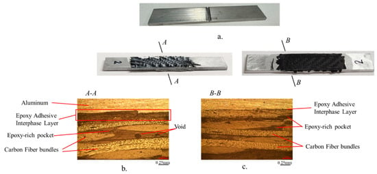
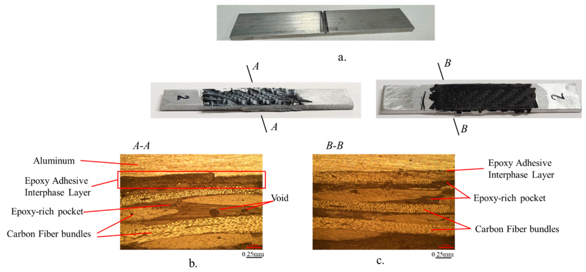
Two fabrication methods were used: manual wet layup and vacuum bagging. For manual wet layup, each carbon-fiber ply was impregnated with the epoxy system and applied sequentially to the prepared aluminum surface. For vacuum bagging, the impregnated plies were applied similarly and then enclosed in a vacuum bag. A vacuum pressure of approximately −85 kPa gauge (25 inHg vacuum) was maintained for 8 h to consolidate the laminate during the initial curing stage. Specimens produced by both methods were cured for 24 h at 25 °C. Figure 1 presents the untreated and CFRP-reinforced specimens together with representative cross-sectional images. The wet-layup specimen exhibited a visually thicker resin-rich region at the CFRP–aluminum interface, whereas the vacuum-bagged specimen displayed a more compact laminate structure.
Figure 1.
(a) Untreated notched aluminum specimen. (b) Wet layup-reinforced specimen. (c) Vacuum-assisted layup-reinforced specimen.
2.3. Testing Procedure
Mechanical testing was conducted on unnotched aluminum, untreated notched aluminum, and CFRP-reinforced notched specimens. Tensile testing was performed using a Shimadzu AGS-X (Kyoto, Japan) universal testing machine with a 50-kN load-cell capacity. The testing procedure was adapted from ASTM E8/E8M [29], and the specimens were loaded under displacement control at a crosshead speed of 1 mm/min. An extensometer with a gauge length of 25 mm was mounted across the central region of each specimen, with one contact on the aluminum side and the opposite contact on the CFRP-reinforced side, to measure axial strain. Load, displacement, and extensometer strain were recorded continuously using TRAPEZIUMX version 1.5.6 software. Five specimens were prepared and tested for each reinforced and reference condition in each loading mode. Nominal engineering stress and engineering strain were calculated using Equations (1) and (2).
where is the nominal engineering stress (MPa), P is the applied load (N), A0 is the original gross cross-sectional area of the aluminum substrate (125 mm2), ε is the engineering strain, ΔL is the elongation measured by the extensometer (mm), and L0 is the extensometer gauge length (mm). Nominal tensile strength was determined from the maximum applied load. The apparent tensile modulus was obtained from the slope of the initial linear region of the nominal stress–strain curve using the same fitting interval for all specimens.
Three-point bending tests were conducted using the same testing machine following a procedure adapted from ASTM D790 [30]. The specimens were placed on supports with an 80 mm span and loaded at the specimen midspan at a crosshead speed of 1 mm/min. The CFRP-reinforced face was positioned on the tensile side during testing. Load and midspan displacement were recorded continuously using TRAPEZIUMX software.
Nominal flexural stress and flexural strain were calculated using Equations (3) and (4).
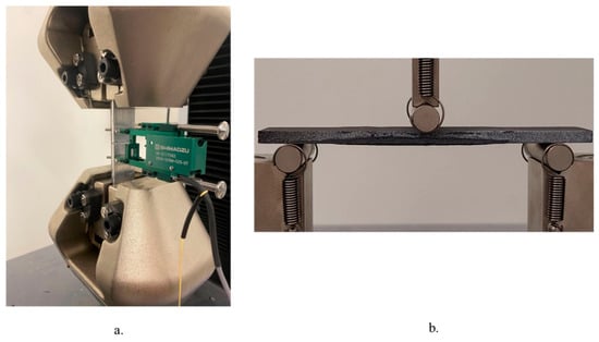
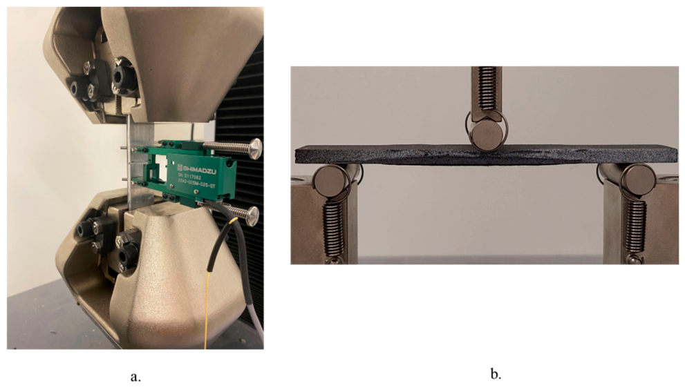
where σf is the nominal flexural stress (MPa), P is the applied load (N), L is the support span (80 mm), b is the aluminum specimen width (25 mm), d is the aluminum specimen thickness (5 mm), εf is the nominal flexural strain, and D is the midspan displacement (mm). Flexural strain was multiplied by 100 when reported as a percentage. Nominal flexural strength was determined from the maximum nominal flexural stress. The apparent flexural modulus was calculated from the slope of the initial linear region of the nominal flexural stress–strain curve. Dimensionless strain values were used to calculate both moduli, although flexural strain is presented as a percentage in the corresponding figures. Because the CFRP reinforcement creates an asymmetric, non-prismatic, and materially nonuniform cross-section, the ASTM D790 expressions (Equations (3) and (4)) were used only to provide nominal stress–strain quantities normalized to the original aluminum geometry (b = 25 mm, d = 5 mm) and to enable comparison among specimen groups. These values do not represent the true local flexural stress or the composite section’s intrinsic modulus. Because L, b, and d were identical for all specimens, nominal flexural strength is directly proportional to peak load, and apparent flexural modulus is directly proportional to initial load–deflection stiffness. To provide an additional measure of bending response that does not depend on assumed cross-sectional properties, the peak load and the initial slope of the load–midspan-deflection curve were reported (Table 2). Figure 2 shows the experimental setups used for (a) tensile testing with an extensometer and (b) three-point bending testing.
Table 2.
Flexural properties of all specimen conditions.
Figure 2.
(a) Tensile test setup. (b) Three-point bending test.
3. Results
3.1. Tensile Behavior
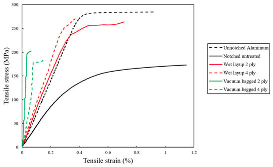
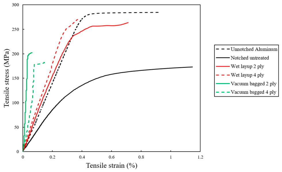
The representative nominal tensile stress–strain curves shown in Figure 3 compare the mechanical responses of the unnotched aluminum, untreated notched aluminum, and CFRP-reinforced notched specimens produced using different fabrication methods and ply counts. The unnotched aluminum specimen reached a nominal tensile strength of approximately 285 MPa. Introducing the notch reduced the maximum nominal stress to approximately 170 MPa, demonstrating the substantial effect of the notch on the specimen’s tensile load-bearing capacity. All representative CFRP-reinforced specimens exhibited higher nominal tensile strengths than the representative untreated notched specimen. The representative wet-layup two- and four-ply specimens both reached approximately 270MPa, indicating that increasing the wet-layup reinforcement from two to four plies did not noticeably increase the peak nominal tensile stress. The representative vacuum-bagged two- and four-ply specimens reached approximately 201 and 180 MPa, respectively. Although these values exceeded that of the untreated notched specimen, they remained lower than those of the corresponding wet-layup specimens. Because Figure 3 presents representative specimens, the peak values shown in these curves may differ from the mean values reported in Figure 4.
Figure 3.
Representative nominal tensile stress–strain curves for unnotched aluminum, untreated notched aluminum, and CFRP-reinforced notched specimens.
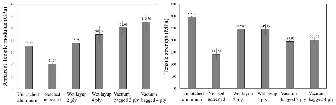
Figure 4.
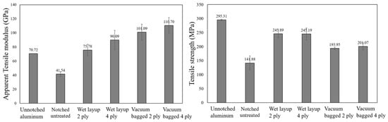
Mean apparent tensile modulus (left) and nominal tensile strength (right) for all specimen conditions. (n = 5); error bars represent one standard deviation.
Figure 4 compares the mean apparent tensile modulus and nominal tensile strength for all specimen conditions. The unnotched aluminum exhibited a mean apparent tensile modulus of 70.72 ± 2 GPa, which is consistent with the expected elastic modulus of 6061 aluminum. The untreated notched condition exhibited a lower mean apparent modulus of 41.54 ± 3 GPa, representing a reduction of approximately 41%. This reduction reflects the greater specimen-level compliance associated with the notched geometry rather than a change in the intrinsic elastic modulus of the aluminum. The wet-layup two- and four-ply configurations exhibited mean apparent tensile moduli of 75.78 ± 8 GPa and 90.09 ± 13 GPa, respectively. The corresponding vacuum-bagged configurations produced mean values of 101.09 ± 11 GPa and 110.70 ± 11 GPa. Relative to the untreated notched condition, all CFRP configurations increased the mean apparent tensile modulus. Increasing the reinforcement from two to four plies also increased the mean apparent modulus for both fabrication methods. The vacuum-bagged four-ply configuration produced the highest mean apparent tensile modulus, approximately 57% greater than that of the unnotched aluminum specimen.
The reported apparent moduli represent the stiffness response of the reinforced specimens rather than the intrinsic elastic modulus of either the aluminum or CFRP. These values were calculated using the original aluminum cross-sectional dimensions, while the bonded CFRP reinforcement also contributed to load transfer and specimen stiffness. Therefore, apparent modulus values exceeding the elastic modulus of unreinforced aluminum should not be interpreted as changes in the intrinsic properties of the aluminum substrate. The higher mean apparent moduli of the vacuum-bagged specimens may be associated with differences in laminate consolidation, patch thickness, and resin distribution. However, fiber volume fraction, void content, cured patch thickness, resin content, and bondline thickness were not quantitatively measured; therefore, the observed differences cannot be uniquely attributed to any single laminate or interfacial parameter.
The nominal tensile-strength results followed a different trend. The mean nominal tensile strength decreased from 295.31 ± 3 MPa for the unnotched aluminum to 141.88 ± 25 MPa for the untreated notched condition, corresponding to a reduction of approximately 52%. The wet-layup two- and four-ply configurations exhibited mean nominal tensile strengths of 245.89 ± 14 MPa and 245.19 ± 21 MPa, respectively. These values represent improvements of approximately 73% relative to the untreated notched condition and approximately 68% recovery of the strength lost because of the notch. Both wet-layup configurations retained approximately 83% of the mean strength of the unnotched aluminum. Their nearly identical mean values indicate that increasing the wet-layup reinforcement from two to four plies did not provide an additional tensile-strength benefit.
The vacuum-bagged two- and four-ply configurations exhibited mean nominal tensile strengths of 193.95 ± 5 MPa and 201.07 ± 13 MPa, respectively. These values correspond to improvements of approximately 37% and 42% relative to the untreated notched condition. They retained approximately 66% and 68% of the mean unnotched aluminum strength and recovered approximately 34% and 39%, respectively, of the strength lost because of the notch. Thus, vacuum bagging increased the mean nominal tensile strength relative to the untreated notched condition, but the strength recovery was lower than that obtained using wet layup.
Overall, all CFRP configurations increased the mean nominal tensile strength and apparent tensile modulus relative to the untreated notched condition. The vacuum-bagged configurations exhibited higher mean apparent tensile moduli but lower mean nominal tensile strengths than the corresponding wet-layup configurations. Increasing the ply count increased the mean apparent tensile modulus for both fabrication methods, whereas its effect on mean nominal tensile strength was negligible for wet layup and relatively small for vacuum bagging. Because statistical significance was not evaluated, these comparisons describe differences among the measured mean values.
The observed contrast between strength and apparent stiffness can therefore be interpreted in terms of the different structural roles of laminate consolidation and interfacial load transfer. The more compact vacuum-bagged laminate may have contributed to the higher apparent stiffness, whereas the thicker resin-rich region observed in the wet-layup specimens may have provided a more compliant interface that allowed more gradual load transfer and delayed localized interfacial damage, contributing to the higher measured strength. Conversely, the greater stiffness of the vacuum-bagged reinforcement may have increased local stiffness mismatch and interfacial stresses near the notch and patch edges, thereby limiting strength recovery.
3.2. Flexural Behavior
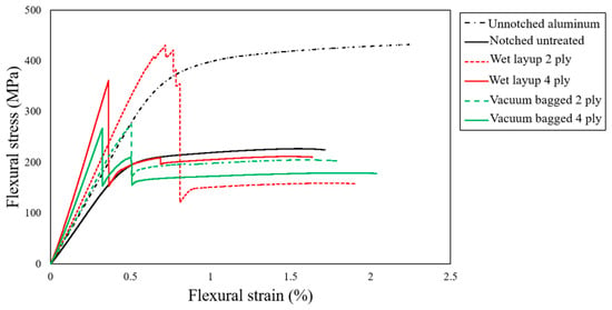
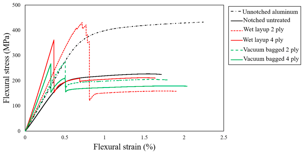
The representative nominal flexural stress–strain curves presented in Figure 5 compare the bending responses of unnotched aluminum, untreated notched aluminum, and CFRP-reinforced notched specimens under three-point bending. The unnotched aluminum specimen exhibited a gradual response, reaching a nominal flexural stress of approximately 430 MPa at a flexural strain of approximately 2%. No sudden load reduction was observed, consistent with the ductile deformation of the aluminum substrate. The untreated notched specimen reached approximately 210 MPa, demonstrating the reduction in flexural load-bearing capacity caused by the notch. The wet-layup specimens exhibited the greatest flexural-strength recovery among the reinforced conditions. The representative wet-layup two-ply specimen reached a peak nominal flexural stress of approximately 420 MPa at a flexural strain of approximately 0.7%, followed by a sudden load reduction and continued residual load-bearing capacity. The wet-layup four-ply specimen reached approximately 360 MPa before a sudden load reduction at approximately 0.3% strain. Therefore, the representative curves indicate that increasing the wet-layup reinforcement from two to four plies did not improve peak nominal flexural stress. The vacuum-bagged specimens reached peak nominal flexural stresses of approximately 260–280 MPa in the representative curves. Following the initial load reduction, both configurations retained stresses of approximately 170–200 MPa over a relatively large strain range. This post-peak response was consistent with CFRP debonding followed by continued deformation and load bearing by the aluminum substrate. However, the vacuum-bagged specimens exhibited lower peak nominal flexural stresses than the corresponding wet-layup specimens. The individual stress–strain data and curves for all specimens are provided in Supplementary File S1.
Figure 5.
Representative nominal flexural stress–strain curves for unnotched aluminum, untreated notched aluminum, and CFRP-reinforced notched specimens.
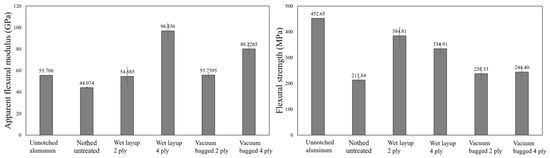
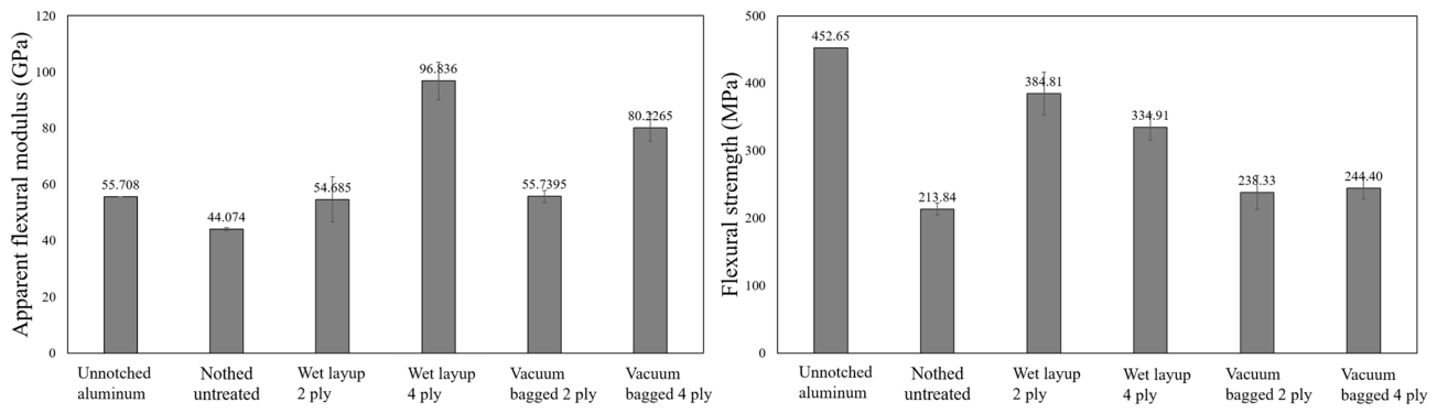
Figure 6 compares the mean apparent flexural modulus and nominal flexural strength for all specimen conditions. The mean nominal flexural strength decreased from 452.65 ± 8 MPa for the unnotched aluminum to 213.84 ± 9 MPa for the untreated notched condition, corresponding to a reduction of approximately 53%. The wet-layup two- and four-ply configurations exhibited mean nominal flexural strengths of 384.81 ± 32 MPa and 334.91 ± 19 MPa, respectively. Relative to the untreated notched condition, these mean values represent improvements of approximately 80% and 57%, respectively. Therefore, the wet-layup two-ply configuration provided the greatest mean flexural-strength recovery among the reinforced conditions. The vacuum-bagged two- and four-ply configurations exhibited mean nominal flexural strengths of 238.33 ± 25 MPa and 244.40 ± 16 MPa, corresponding to improvements of approximately 11% and 14%, respectively. The relatively small difference between these mean values indicates that increasing the ply count provided only a limited improvement in nominal flexural strength for the vacuum-bagged specimens.
Figure 6.
Mean apparent flexural modulus (left) and nominal flexural strength (right) for all specimen conditions (n = 5); error bars represent one standard deviation.
The apparent flexural modulus followed a different trend. The unnotched and untreated notched specimens exhibited mean apparent flexural moduli of 55.71 ± 2 GPa and 44.07 ± 0.5 GPa, respectively. The wet-layup two-ply configuration produced a mean apparent flexural modulus of 54.69 ± 8 GPa, whereas the four-ply configuration reached 96.84 ± 7 GPa, the highest mean value among all conditions. The vacuum-bagged two- and four-ply configurations exhibited mean apparent flexural moduli of 55.74 ± 2 GPa and 80.23 ± 5 GPa, respectively. Thus, increasing the reinforcement from two to four plies increased the mean apparent flexural modulus for both fabrication methods.
The results demonstrate that the fabrication method and ply count affected strength and apparent stiffness differently. Wet-layup reinforcement produced higher mean nominal flexural strengths than the corresponding vacuum-bagged configurations, whereas increasing the ply count primarily increased the apparent flexural modulus. Although vacuum consolidation commonly improves laminate compaction and reduces void content, these characteristics were not measured directly in the present study. Therefore, the lower strengths of the vacuum-bagged specimens cannot be attributed conclusively to a particular material or interfacial mechanism. Differences in resin distribution, patch thickness, interfacial bonding, and stress transfer near the notch and patch edges may have contributed to the observed behavior. Likewise, the reduction in mean flexural strength from the wet-layup two-ply to four-ply configuration may reflect changes in reinforcement stiffness and deformation localization, but additional interfacial and microstructural characterization would be required to confirm the underlying mechanism.
Overall, all CFRP-reinforced configurations produced higher mean nominal flexural strength and apparent flexural modulus than the untreated notched condition. The wet-layup two-ply configuration provided the greatest flexural-strength recovery, while the wet-layup four-ply configuration produced the highest apparent flexural modulus. These results indicate that adding more CFRP plies does not necessarily improve flexural strength, although it can increase specimen-level apparent stiffness. Because statistical significance has not been established, the comparisons reported here refer to differences between the measured mean values.
3.3. Failure Behavior
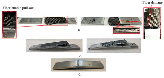
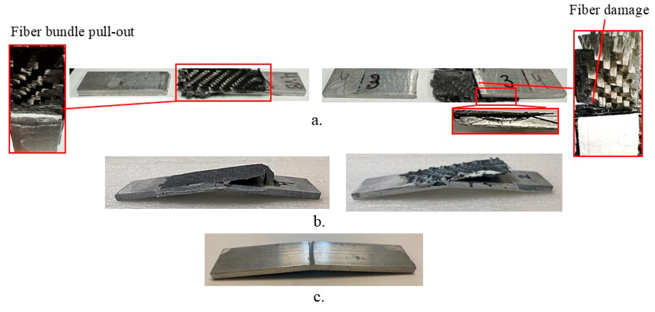
The failed specimens shown in Figure 7 provide qualitative insight into the damage mechanisms observed under tensile and flexural loading. Specimens within each experimental group exhibited similar overall failure behavior; therefore, Figure 7 presents representative specimens selected to illustrate the recurring damage features observed for each group. Figure 7a shows representative wet-layup and vacuum-bagged specimens after tensile testing. The wet-layup specimen exhibited visible fiber-bundle pull-out near the notched region. Following fracture of the aluminum substrate across the notched region, the CFRP reinforcement remained attached to one side of the specimen but separated from the opposite side, indicating that the patch carried load before localized debonding occurred during final failure. The vacuum-bagged specimen exhibited more localized CFRP damage near the notch; however, additional interfacial and microscopic characterization would be required to distinguish conclusively among fiber, matrix, cohesive, and adhesive failure mechanisms. Under flexural loading, Figure 7b shows visible CFRP peeling and debonding from the aluminum substrate in both reinforced configurations. The specimens retained substantial deformation after the initial damage event, consistent with the post-peak load-bearing response observed in the flexural stress–strain curves. Figure 7c shows the untreated notched aluminum specimen after three-point bending. The specimen underwent substantial permanent bending without complete fracture, demonstrating the ductile response of the aluminum substrate under the applied loading conditions. The trends reported in this study are specific to the tested specimen geometry, CFRP patch dimensions, WEST SYSTEM 105/205 epoxy system, 120-grit aluminum surface preparation, notch geometry, and two- and four-ply reinforcement configurations. Changes in patch geometry, adhesive properties, surface treatment, or notch severity may alter laminate–substrate load transfer, local stress concentrations, and failure behavior.
Figure 7.
Representative post-test specimens: (a) tensile, (b) flexural, and (c) untreated notched aluminum after bending. Wet-layup specimens are shown on the left and vacuum-bagged specimens on the right in (a) and (b).
4. Conclusions
This study evaluated the effects of fabrication method and CFRP ply count on the tensile and flexural performance of notched 6061-T6511 aluminum specimens. Introducing the notch reduced the mean nominal tensile and flexural strengths by approximately 52% and 53%, respectively, compared with the unnotched aluminum. All CFRP-reinforced configurations improved the mean strength and apparent modulus relative to the untreated notched condition, confirming the effectiveness of externally bonded CFRP reinforcement in restoring specimen-level mechanical performance. Wet-layup reinforcement provided the greatest strength recovery. The wet-layup two-ply configuration increased nominal tensile and flexural strengths by approximately 73% and 80%, respectively, relative to the untreated notched specimens. Increasing the wet-layup reinforcement from two to four plies produced almost no change in tensile strength and reduced flexural strength, although it increased both apparent tensile and flexural moduli. Vacuum-bagged specimens exhibited lower tensile and flexural strengths than the corresponding wet-layup specimens but higher apparent tensile moduli. The vacuum-bagged four-ply configuration produced the highest apparent tensile modulus of 110.70 GPa, whereas the wet-layup four-ply configuration produced the highest apparent flexural modulus of 96.84 GPa. Overall, increasing the CFRP ply count primarily improved specimen stiffness but did not consistently increase strength. Among the configurations investigated, the wet-layup two-ply reinforcement provided the greatest tensile and flexural strength recovery, whereas the four-ply configurations produced higher apparent moduli. Within the tested configurations, these findings demonstrate that both fabrication method and ply count should be considered when selecting CFRP reinforcement for notched aluminum components, as they influence the balance between nominal strength and apparent stiffness.
Supplementary Materials
The following supporting information can be downloaded at https://www.mdpi.com/article/10.3390/fib14110132/s1, Supplementary File S1: Excel file containing the individual stress–strain data and curves for all tested specimen conditions..
Author Contributions
Conceptualization, S.S.; Methodology, S.S.; Validation, J.W. (Jacey Wright); Formal Analysis, J.W. (Jacey Wright), J.W. (John Weatherford) and M.S.; Investigation, J.W. (Jacey Wright) and J.W. (John Weatherford); Data Curation, J.W. (Jacey Wright), J.W. (John Weatherford) and M.S.; Writing—Original Draft, J.W. (Jacey Wright) and S.S.; Writing—Review and Editing, M.S. and S.S.; Visualization, J.W. (Jacey Wright); Supervision, S.S.; Project Administration, S.S. All authors have read and agreed to the published version of the manuscript.
Funding
This research received no external funding.
Data Availability Statement
The raw data supporting the conclusions of this article will be made available by the authors on request.
Conflicts of Interest
The authors declare no conflicts of interest.
References
- Sun, Y. The use of aluminum alloys in structures: Review and outlook. Structures 2023, 57, 105290. [Google Scholar] [CrossRef] [Scilit]
- Nakai, M.; Eto, T. New aspect of development of high strength aluminum alloys for aerospace applications. Mater. Sci. Eng. A 2000, 285, 62–68. [Google Scholar] [CrossRef] [Scilit]
- USA National Bureau of Standards. Journal of Research of the National Bureau of Standards; US Government Printing Office: Washington, DC, USA, 1954.
- Yen, C.S.; Dolan, T.J. Yen, C.S.; Dolan, T.J. A critical review of the criteria for notch-sensitivity in fatigue of metals. Univ. Ill. Eng. Exp. Stn. Bull. 1952, 49, 398. Available online: https://hdl.handle.net/2142/4249 (accessed on 9 February 2026).
- Lei, X.; Li, C.; Shi, X.; Xu, X.; Wei, Y. Notch strengthening or weakening governed by transition of shear failure to normal mode fracture. Sci. Rep. 2015, 5, 10537. [Google Scholar] [CrossRef] [Scilit] [PubMed]
- Zhu, L.; Li, N.; Childs, P.R.N. Light-weighting in aerospace component and system design. Propuls. Power Res. 2018, 7, 103–119. [Google Scholar] [CrossRef] [Scilit]
- Zichil, V.; Grigoras, C.C.; Ciubotariu, V.A. Notches and Fatigue on Aircraft-Grade Aluminium Alloys. Materials 2024, 17, 4639. [Google Scholar] [CrossRef] [Scilit] [PubMed]
- Sattar, S.; Pedrazzoli, D.; Zhang, M.; Kravchenko, S.G.; Kravchenko, O.G. Notched tensile strength of long discontinuous glass fiber reinforced nylon composite. Compos. Part Appl. Sci. Manuf. 2022, 163, 107217. [Google Scholar] [CrossRef] [Scilit]
- Saquib, M.N.; Chaparro-Chavez, E.; Sattar, S.; Pedrazzoli, D.; Zhang, M.; Kravchenko, S.G.; Kravchenko, O.G. Effect of local meso-structure on mechanical variability and notch strength sensitivity in woven glass fiber polyamide composites. Compos. Part Appl. Sci. Manuf. 2025, 198, 109061. [Google Scholar] [CrossRef] [Scilit]
- Wright, J.; Sikes, M.; Richard, K.; Sheldon, P.; Sattar, S. Effect of Raster Orientation and Notch Preparation on Fracture Toughness and Energy Release Rate of FFF-Printed Glass Fiber-Reinforced Polyamide Composites. Appl. Compos. Mater. 2026, 33, 110. [Google Scholar] [CrossRef] [Scilit]
- Zhou, W.; Ji, X.; Yang, S.; Liu, J.; Ma, L. Review on the performance improvements and non-destructive testing of patches repaired composites. Compos. Struct. 2021, 263, 113659. [Google Scholar] [CrossRef] [Scilit]
- Nazemi, N. Identification of the Mechanical Properties in the Heat-Affected Zone of Aluminum Welded Structures. 2015. Available online: https://hdl.handle.net/20.500.14776/5475 (accessed on 16 February 2026).
- Pilkey, W.D.; Pilkey, D.F.; Bi, Z. Peterson’s Stress Concentration Factors; John Wiley & Sons: Hoboken, NJ, USA, 2020. [Google Scholar]
- Van Den Einde, L.; Zhao, L.; Seible, F. Use of FRP composites in civil structural applications. Constr. Build. Mater. 2003, 17, 389–403. [Google Scholar] [CrossRef] [Scilit]
- Wu, Z.; Wang, X.; Iwashita, K. State-of-the-Art of Advanced FRP Applications in Civil Infrastructure in Japan. Compos. Polycon 2007, 37, 1–17. [Google Scholar]
- Okafor, A.C.; Singh, N.; Enemuoh, U.E.; Rao, S.V. Design, analysis and performance of adhesively bonded composite patch repair of cracked aluminum aircraft panels. Compos. Struct. 2005, 71, 258–270. [Google Scholar] [CrossRef] [Scilit]
- Baker, A. Bonded composite repair of fatigue-cracked primary aircraft structure. Compos. Struct. 1999, 47, 431–443. [Google Scholar] [CrossRef] [Scilit]
- Aakkula, J.; Saarela, O. An experimental study on the fatigue performance of CFRP and BFRP repaired aluminium plates. Compos. Struct. 2014, 118, 589–599. [Google Scholar] [CrossRef] [Scilit]
- da Silva, L.F.M.; Öchsner, A.; Adams, R.D. Handbook of Adhesion Technology; Springer Science & Business Media: Berlin/Heidelberg, Germany, 2011. [Google Scholar]
- Balkundhi, M.; Baloor, S.S.; Bolar, G. Assessment of surface treatment methods for strengthening the interfacial adhesion in CARALL fiber metal laminates. Sci. Rep. 2024, 14, 30909. [Google Scholar] [CrossRef] [Scilit] [PubMed]
- Zhang, J.; Peng, J.; Hou, C.; Lin, G. Experimental study on bond behavior between wet lay-up CFRP and corroded steel plates. Constr. Build. Mater. 2024, 438, 137024. [Google Scholar] [CrossRef] [Scilit]
- Amirkhosravi, M.; Pishvar, M.; Altan, M.C. Improving laminate quality in wet lay-up/vacuum bag processes by magnet assisted composite manufacturing (MACM). Compos. Part Appl. Sci. Manuf. 2017, 98, 227–237. [Google Scholar] [CrossRef] [Scilit]
- Sattar, S.; Laredo, B.B.; Kravchenko, S.G.; Kravchenko, O.G. Effect of platelet length and stochastic morphology on flexural behavior of prepreg platelet molded composites. Polym. Compos. 2023, 44, 2122–2137. [Google Scholar] [CrossRef] [Scilit]
- Mallick, P.K. Fiber-Reinforced Composites: Materials, Manufacturing, and Design, 3rd ed.; CRC Press: Boca Raton, FL, USA, 2007. [Google Scholar] [CrossRef] [Scilit]
- Qiao, Y.; Seffens, R.J.; Nickerson, E.K.; Roosendaal, T.J.; Merkel, D.R.; Shin, Y.; Ramos, J.L.; Ko, S.; Samanta, A.; Pallaka, M.R.; et al. A study of adhesive bonding in metal–metal, metal–CFRP, and CFRP–CFRP material combinations under shear deformation: Fracture morphologies and damage mechanisms. Int. J. Adhes. Adhes. 2023, 127, 103511. [Google Scholar] [CrossRef] [Scilit]
- Zakaria, M.R.; Ahmad Thirmizir, M.Z.; Zainol Abidin, M.S.; Md Akil, H.; Omar, M.F.; Anjang Ab Rahman, A.; Nosbi, N.; Ghafar, N.A. A Comparison Process Between Wet Lay-Up, Single Vacuum Bagging and Double Vacuum Bagging Toward Natural Fibre (Palm, Coconut and Kenaf) Reinforced Epoxy Composite Laminates. Fibers Polym. 2023, 24, 2107–2116. [Google Scholar] [CrossRef] [Scilit]
- Baker, A.A. Fibre composite repair of cracked metallic aircraft components—Practical and basic aspects. Composites 1987, 18, 293–308. [Google Scholar] [CrossRef] [Scilit]
- Sussmann, M.; Amirkhosravi, M.; Pishvar, M.; Altan, M.C. Fabrication of High Quality, Large Wet Lay-Up/Vacuum Bag Laminates by Sliding a Magnetic Tool. Polymers 2018, 10, 992. [Google Scholar] [CrossRef] [Scilit] [PubMed]
- Standard’s ASTM E8/E8M-25; Standard Test Methods for Tension Testing of Metallic Materials. ASTM International: West Conshohocken, PA, USA, 2025.
- Standard’s ASTM D790-25; Standard Test Methods for Flexural Properties of Unreinforced and Reinforced Plastics and Electrical Insulating Materials. ASTM International: West Conshohocken, PA, USA, 2025.

Disclaimer/Publisher’s Note: The statements, opinions and data contained in all publications are solely those of the individual author(s) and contributor(s) and not of MDPI and/or the editor(s). MDPI and/or the editor(s) disclaim responsibility for any injury to people or property resulting from any ideas, methods, instructions or products referred to in the content. |
© 2026 by the authors. Licensee MDPI, Basel, Switzerland. This article is an open access article distributed under the terms and conditions of the Creative Commons Attribution (CC BY) license.