


Abstract
Conventional low-loss Hollow-Core Anti-Resonant Fibers (ARFs) deliver a near-Gaussian fundamental mode profile that is suboptimal for applications favoring uniform irradiance. We show here that deliberately breaking the cladding symmetry can allow for delivering a low-loss fundamental mode with a top-hat intensity profile, with no need for mode mixing or external beam-shaping optics. By enlarging one pair of nested cladding capillaries relative to the orthogonal pair, the core is elongated and the y-polarized fundamental mode reshapes from a near-Gaussian distribution into a flat-top profile whose 90%-intensity plateau width is wider than that of a symmetric reference fiber at . Full-vectorial simulations show that this plateau varies by less than across the 900–1600 nm near-infrared guidance band, where the confinement loss falls below 1 dB/km, and that the shaping mechanism persists essentially unchanged from the visible to the mid-infrared, where the overall attenuation remains below 0.1 dB/m within the 2700–3200 nm wavelength range. These results establish a purely geometric route to broadband top-hat beam delivery in anti-resonant hollow-core fibers.
1. Introduction
Uniform, top-hat irradiance distributions are required across a wide range of laser applications, including material processing, laser annealing, welding and drilling, medical treatment, and the uniform optical addressing of qubit arrays in trapped-ion and neutral-atom quantum computing platforms [1,2], where a flat intensity profile lowers the peak fluence for a given delivered power and improves processing uniformity compared with the Gaussian output of most laser sources [3,4]. Historically, the first beam-shaping strategies relied on refractive optics, most notably pairs of aspheric lenses designed to redistribute a Gaussian irradiance profile into a flat-top one with minimal loss [3]. This approach was subsequently generalized to phase-only diffractive optical elements (DOEs), whose surface-relief or multi-level phase profiles can be synthesized via iterative Fourier-transform algorithms, most notably the Gerchberg–Saxton algorithm and its later variants, to produce almost arbitrary target irradiance distributions with high diffraction efficiency [5,6].
Spatial light modulators (SLMs) extended this concept by making the phase (or complex) modulation reconfigurable in real time, enabling dynamic, programmable beam shaping without the need for a bespoke fixed optical element for each target profile [7,8,9]. However, both DOE- and SLM-based approaches are free-space components external to the beam delivery path: they require precise alignment, introduce additional insertion loss, and are difficult to integrate directly into a guided-wave delivery system, which limits their applicability.
An alternative route, pursued directly within optical fibers, is to deliberately excite and combine several higher-order modes—via long-period or few-mode fiber Bragg gratings, specialty doping profiles, or tailored core geometries—so that their superposition approximates a flat-top profile at the fiber output [10,11,12]. Related solid-core strategies achieve a similar goal by engineering the refractive-index landscape of the core itself, for instance through nanostructured or doped-core photonic crystal fibers designed to flatten the fundamental-mode intensity profile directly [13,14,15]. While effective, mode-mixing approaches remain susceptible to long-term instability, as the relative phase and amplitude of the interfering modes drift with temperature and mechanical perturbation, and all solid-core routes are intrinsically constrained by the material damage threshold and nonlinearity of the glass through which the beam propagates.
Hollow-core fibers offer, in principle, a way to decouple beam shaping from these material limitations since guiding light predominantly in air minimizes light–glass overlap and hence nonlinearity and damage-related constraints at high power. The concept of guiding light in a hollow dielectric channel dates back to the leaky-mode analysis of hollow metallic and dielectric waveguides [16], but practical low-loss hollow-core guidance only became possible with the advent of microstructured claddings, beginning with photonic-bandgap guidance of light in air [17] and the first kagome-lattice fiber exploiting an inhibited-coupling mechanism rather than a true bandgap [18]. The antiresonant reflecting optical waveguide (ARROW) condition [19,20] provided the conceptual bridge between these early designs and modern anti-resonant fibers (ARFs), whose negative-curvature core boundary was later demonstrated explicitly [21] and extensively reviewed and refined [22,23]. The introduction of additional nested antiresonant elements within the cladding voids [24] and nodeless designs [25,26] paved the way to nested-antiresonant-nodeless-fiber (NANF) designs down to record levels [27,28,29], establishing HC-ARFs as a leading platform for low-nonlinearity high-power beam delivery [30].
Virtually all of these state-of-the-art HC-ARFs designs preserve a high degree of cladding rotational symmetry, which is precisely what yields their near-circular core and, in turn, a near-Gaussian fundamental-mode intensity profile: the symmetry that makes these fibers so effective for low-loss delivery is the same symmetry that prevents them from producing a top-hat output. If a rotationally symmetric cladding systematically yields a Gaussian-like fundamental mode, an alternative route is to engineer the cladding asymmetry itself as the beam-shaping element—reshaping the fundamental mode directly through fiber geometry, with no mode mixing, no external optics, and no free-space alignment required.
A structural element that has recently emerged as a versatile tool for introducing controlled anti-resonant asymmetry is the semicircular (semi-tube) cladding element, in which a conventional circular anti-resonant tube is replaced by a half-tube facing the core. Fourfold semi-tube claddings have been shown to produce a stronger negative-curvature effect and markedly higher modal birefringence than their fully circular counterparts [31,32], building on the earlier observation that a deliberate wall thickness mismatch between orthogonal cladding elements shifts the two polarization states into distinct hybrid transmission bands [33,34]. This design freedom has since been exploited for polarization-maintaining HC-ARFs optimized via multi-objective genetic algorithms [35], for few-mode HC-ARFs supporting weakly coupled polarization-maintaining mode sets [36], and recently for cladding-engineered, polarization-selective HC-ARFs combining semicircular geometry with high-index coatings [37]. Notably, this entire body of work has so far targeted birefringence and polarization selectivity rather than the spatial shape of the fundamental mode itself, leaving the use of cladding asymmetry for beam shaping in hollow-core fibers largely unexplored.
In this work, we show that a single, passive geometric asymmetry—enlarging one pair of nested cladding capillaries relative to the orthogonal pair—is sufficient to convert the fundamental mode of an HC-ARF directly into a top-hat intensity profile, achieving a purely geometric, broadband beam-shaping mechanism that requires no mode mixing, no external optics, and no active control.
2. Materials and Methods
Fiber Structure Design and Numerical Model
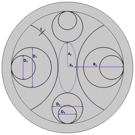
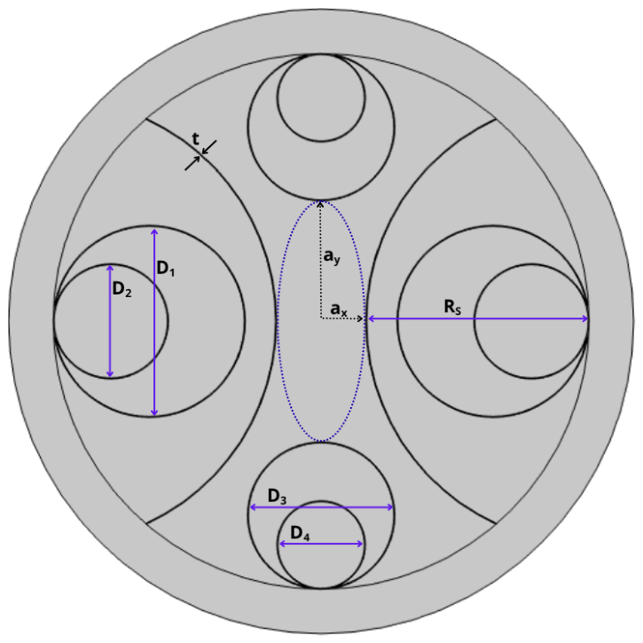
The proposed fiber is an asymmetric hollow-core anti-resonant fiber (HC-ARF) designed to produce an elliptical core with semi-axes and (Figure 1). The cladding is built around a fourfold arrangement of nested capillaries embedded within semicircular elements, following the same class of anti-resonant asymmetric elements recently reported to enhance negative-curvature effects and birefringence in the polarization-maintaining literature [31,32,35]; here, however, the same structural asymmetry is exploited to reshape the fundamental-mode intensity profile rather than to split polarization states.
Figure 1.
Cross-sectional schematic of the proposed asymmetric HC-ARF. Two enlarged horizontal capillaries of diameter , each containing a nested element of diameter , are arranged within semicircular nested elements of radius ; two smaller vertical capillaries of diameters and complete the cladding. The wall thickness t is uniform across all capillaries. The asymmetric arrangement produces an elliptical core of semi-axes and .
The cross-section consists of two enlarged horizontal capillaries of diameter , each containing a nested element of diameter . These are arranged within semicircular nested elements of radius . It is precisely this asymmetric embedding, rather than the presence of the nested elements alone, that constitutes the direct geometric origin of the flat-top mode reshaping discussed in Section 3.1. This is complemented by two smaller vertical capillaries with diameters and . The glass wall thickness is maintained uniform across all capillary structures, according to the anti-resonance condition [19]:
for guidance in the first window () at the design wavelength of , chosen as a representative reference wavelength to analyze the fiber’s behavior in the near-infrared, consistent with the ARROW condition. Across the spectral bands considered in Section 3, the capillary diameters – and the semicircular-element radius that define the core asymmetry are kept fixed; only the glass wall thickness t is rescaled, following the same design offset described above, to shift the low-loss anti-resonant window to the target operating wavelength, as detailed in Section 3. Because t concerns only the anti-resonance condition governing the confinement and not the transverse capillary layout responsible for the core ellipticity, the same structural asymmetry is preserved unchanged across all three bands. Considering that the horizontal capillary pair is enlarged relative to the vertical pair, the resulting core boundary is elliptical rather than circular; the full set of predetermined structural parameters is summarized in Table 1.
Table 1.
Design parameters of the asymmetric HC-ARF.
The fundamental core-guided modes and their complex effective indices were computed by the full-vectorial finite-element method (FEM) on the two-dimensional fiber cross-section described above, with a perfectly matched layer surrounding the outer jacket. Fused-silica dispersion was described by the Sellmeier equation, and silica’s intrinsic material absorption was included for the mid-infrared loss budget of Section 3.2. The confinement loss in dB/m was obtained from the imaginary component of the effective refractive index, consistent with standard practice in the anti-resonant fiber literature [38]:
and the modal birefringence was evaluated as , tracking each polarization branch by mode overlap across the wavelength sweep. The 90%-intensity plateau width was defined as the full transverse width over which the normalized time-averaged power flow exceeds 90% of its peak value, a standard flatness metric in the beam-shaping literature [13,14]. As reference, rotationally symmetric HC-ARF cladding (all capillaries of equal diameter, circular core) was simulated under otherwise identical conditions and used as a baseline for the mode-profile comparisons below. Throughout this work, y denotes the elongated core axis (), along which the flat-top profile of the y-polarized fundamental mode develops, while x denotes the short axis, along which the mode retains a narrower, centrally peaked distribution. In all cross-sectional plots, each profile is taken along its own physical axis: profiles of the y-polarized mode are cut along y, and those of the x-polarized mode along x.
3. Results
3.1. Near-Infrared Performance
Extensive numerical analysis in the near-infrared band confirms the viability of the asymmetric design for flat-top beam shaping.
3.1.1. Top-Hat Profile Expansion
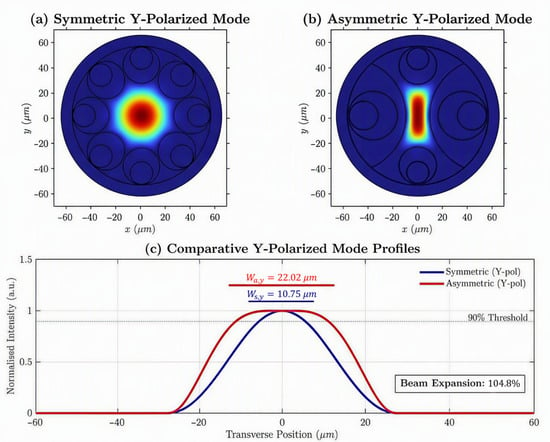
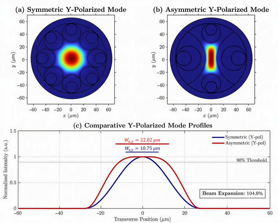
At , the deliberate breaking of symmetry reshapes the y-polarized mode into an elongated flat-top distribution (Figure 2). The asymmetric design yields a 90% plateau width of , compared to for a standard symmetric reference fiber, representing a top-hat beam expansion of .
Figure 2.
Comparison of the y-polarized fundamental mode between the symmetric and asymmetric HC-ARF designs at nm. (a) Near-field intensity map of the symmetric design, showing a circularly symmetric, Gaussian-like distribution. (b) Corresponding map for the asymmetric design, where breaking symmetry reshapes the mode into an elongated flat-top distribution confined along the y-axis. (c) Normalized intensity profiles of the y-polarized mode for both designs, taken along the y-axis, with the 90% uniformity threshold indicated. The asymmetric design yields a 90% plateau width of against for the symmetric reference, a top-hat beam expansion of .
3.1.2. Loss and Dispersion
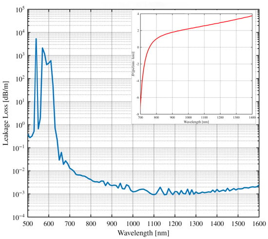
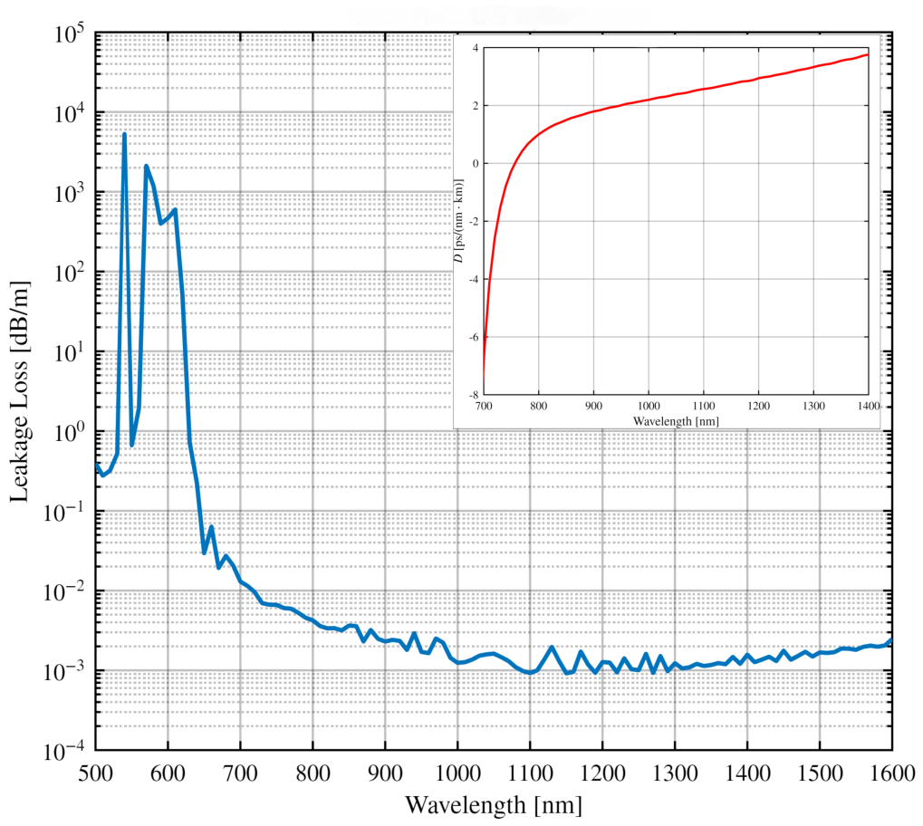
The simulated leakage-loss spectrum across the 500–1600 nm range (Figure 3) reveals high-loss resonance peaks around 550–600 nm, arising when the wall thickness satisfies the resonant condition [19], rather than the anti-resonant condition of Equation (1) that governs the low-loss guidance window. Beyond this resonant region, a broadband low-loss guidance window extends above 800 nm, achieving a minimum confinement loss approaching dB/m near —comparable, in order of magnitude, to the lowest leakage losses reported for state-of-the-art silica nested-antiresonant-nodeless fibers at near-infrared wavelengths [28,29]. Chromatic dispersion exhibits a zero-dispersion crossing near 800 nm, transitioning to anomalous dispersion at the primary operating wavelength of .
Figure 3.
Simulated leakage loss spectrum of the asymmetric HC-ARF across the 500–1600 nm range. High-loss resonance peaks are observed around 550–600 nm, consistent with the ARROW condition for the design capillary wall thickness; a broad low-loss guidance window extends above 800 nm with a minimum confinement loss approaching dB/m near . Inset: chromatic dispersion across 700–1400 nm, exhibiting a zero-dispersion crossing near 800 nm and anomalous dispersion at the primary operating wavelength of .
3.1.3. Modal Birefringence
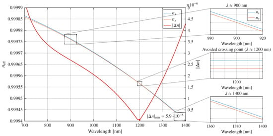
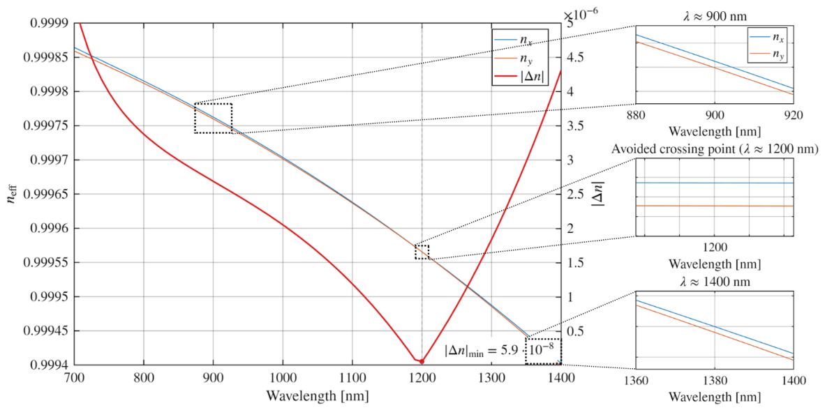
Analysis of the effective indices of the fundamental polarization eigenmodes ( and ) shows that the modal birefringence starts at near 700 nm (Figure 4). It then passes through a minimum of at an avoided-crossing point at 1200 nm, before increasing again at higher wavelengths. This behavior indicates that the same fixed geometry supports both a near-polarization-degenerate operating point near 1200 nm and a polarization-split regime elsewhere in the band, selectable simply through the choice of operating wavelength—an effect analogous to the geometry-induced birefringence exploited deliberately in dedicated polarization-maintaining anti-resonant designs [33,34,39], even though birefringence enhancement is not the objective pursued in this work. We note that, unlike those designs, the birefringence reported here is a side effect of an asymmetry optimized for beam shaping rather than a design target.
Figure 4.
Effective indices (blue curve) and (orange curve) of the two fundamental polarization eigenmodes and the resulting modal birefringence (right axis, red curve) as a function of wavelength across 700–1400 nm. The birefringence starts from near 700 nm and passes through a minimum of at an avoided crossing near 1200 nm before increasing again at higher wavelength. Insets show magnified views of the two effective indices at 900 nm, at the avoided crossing point, and at 1400 nm.
3.1.4. Plateau Stability Across the NIR Band
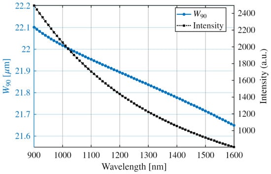
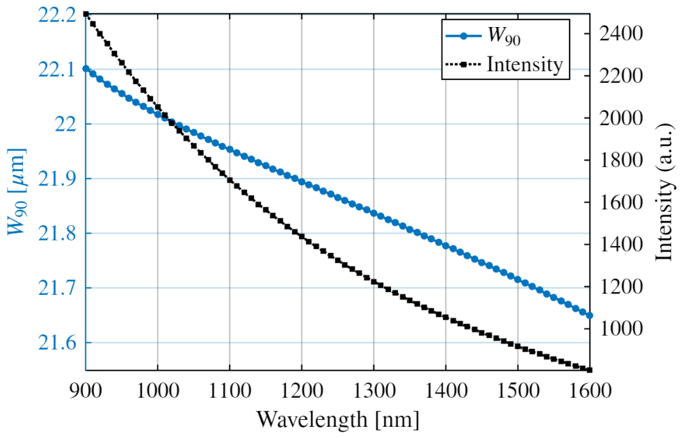
Beyond the single-wavelength expansion demonstrated above, the flat-top plateau is remarkably stable across the entire NIR guidance band (900–1600 nm), as shown in Figure 5. The 90% plateau width decreases monotonically from at 900 nm to at 1600 nm—a total variation of . The peak intensity (in arbitrary units) decreases by approximately a factor of three over this same range, consistent with reduced modal confinement at longer wavelengths.
Figure 5.
Plateau width of 90% (left axis, blue markers) and peak time-averaged power flow (right axis, black markers, in arbitrary units) as a function of wavelength across the NIR guidance band (900–1600 nm).
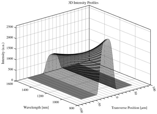
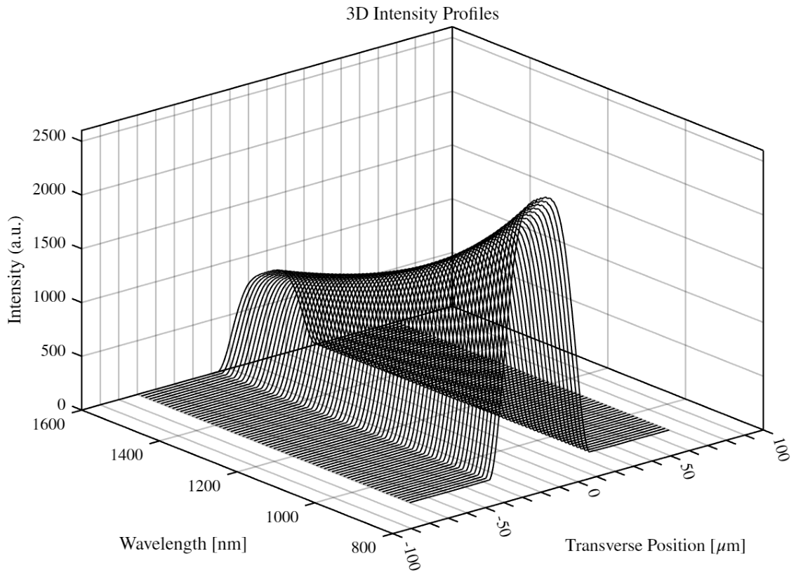
This persistence is confirmed by the full spatial evolution of the mode profile across the band, shown in Figure 6: the flat-top spatial distribution is maintained essentially unchanged in shape at every simulated wavelength, with only a gradual reduction in peak intensity.
Figure 6.
Three-dimensional waterfall representation of the time-averaged power-flow profile (in arbitrary units) as a function of transverse position and wavelength, confirming the persistence of the flat-top spatial distribution across the entire NIR guidance band (900–1600 nm).
3.2. Visible and Mid-Infrared Performance
The intrinsic geometric beam-shaping mechanism established above is not confined to the NIR band; we find that it extends, essentially unchanged, from the visible to the mid-infrared just by scaling the glass thickness t of the cladding elements to obtain guidance in the first anti-resonant window at the target wavelength, according to the ARROW condition of Equation (1), while the transverse capillary layout (–, ) that sets the core asymmetry is left unchanged, as is the core size.
3.2.1. Visible-Range Operation
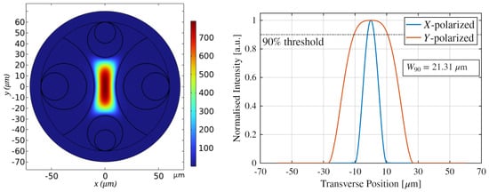
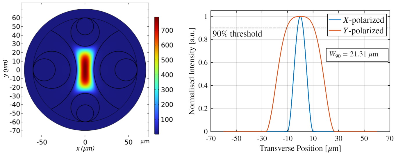
At the yellow laser wavelength ( nm), obtained by rescaling the cladding wall thickness to nm to keep the first-order resonance safely below the operating point, the y-polarized fundamental mode maintains a well-defined flat-top profile with a 90% plateau width of (Figure 7), consistent with the demonstrated viability of anti-resonant guidance well into the visible spectral range [40]. Meanwhile, the x-polarized mode retains a narrower, centrally peaked distribution, underscoring the single-axis, polarization-selective nature of the shaping mechanism.
Figure 7.
Modal analysis at nm. (Left) near-field intensity map of the y-polarized fundamental mode, showing the elongated flat-top distribution confined along the y-axis. (Right) normalized power-flow cross-sections for the x-polarized mode (blue, cut along x) and y-polarized mode (orange, cut along y), overlaid for direct comparison of the plateau widths. The y-polarized mode exhibits a flat-top profile with , while the x-polarized mode retains a narrower, centrally peaked distribution.
3.2.2. Mid-Infrared Loss Budget
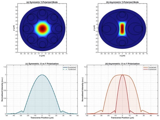
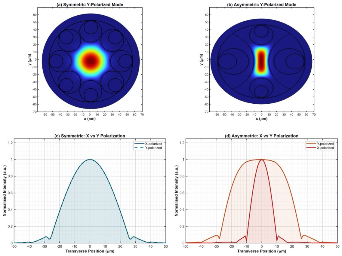
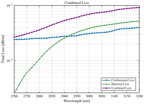
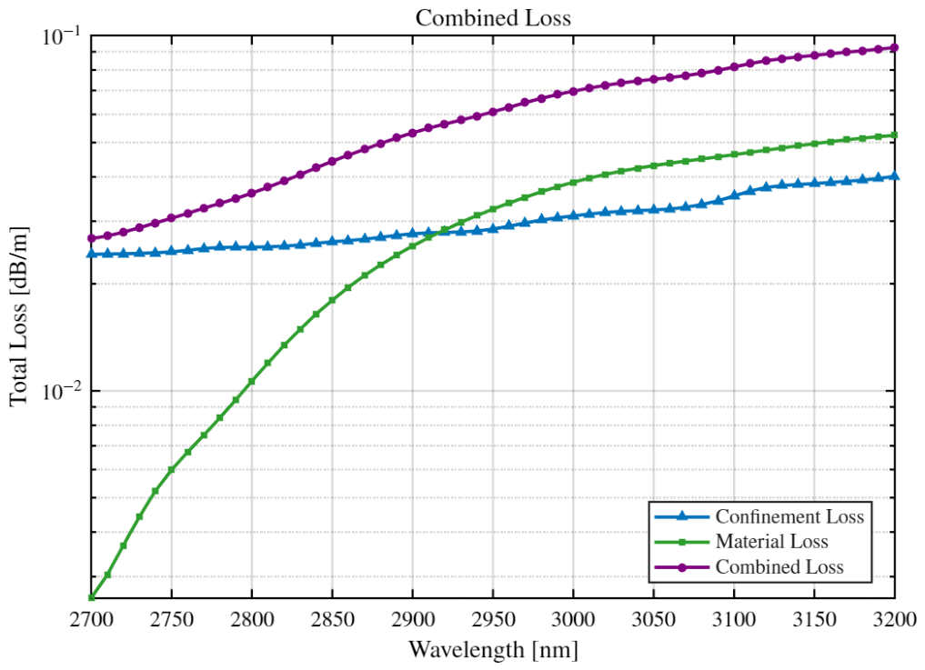
We have rescaled the cladding wall thickness to nm to keep the first-order resonance below the wavelength of , chosen as a representative reference wavelength to analyze the fiber’s behavior in the mid-infrared. In this mid-infrared wavelength regime, symmetry breaking continues to confine the y-polarized mode into an elongated flat-top profile along the y-axis (Figure 8). The confinement loss remains below dB/m across the 2700–3200 nm band (Figure 9). While silica material loss dominates above 2915 nm, consistent with the known onset of the fundamental O–H and Si–O absorption bands of bulk silica [22], the combined total loss remains below 0.1 dB/m, confirming the design’s viability for short-path mid-infrared delivery. The overlap between the guided mode and the silica cladding underlying this loss budget remains below across the band, reflecting the strong confinement afforded by the double-nested cladding.
Figure 8.
Comparison of the fundamental guided mode between the symmetric and asymmetric HC-ARF designs at . (a) Near-field intensity map of the y-polarized mode in the symmetric design (circularly symmetric, Gaussian-like). (b) Corresponding map for the asymmetric design (elongated along y). (c) Symmetric design: degenerate, Gaussian-like x- and y-polarized profiles. (d) Asymmetric design: the y-polarized mode (orange, cut along y) develops a flat-top profile, while the x-polarized mode (dark red, cut along x) retains a narrower, centrally peaked distribution.
Figure 9.
Loss budget of the MIR-scaled asymmetric HC-ARF across 2700–3200 nm. Confinement loss (blue) remains below dB/m; silica material loss (green) becomes dominant above 2915 nm; the combined total loss (purple) remains below 0.1 dB/m.
3.2.3. Mid-Infrared Bending Loss
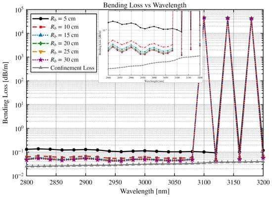
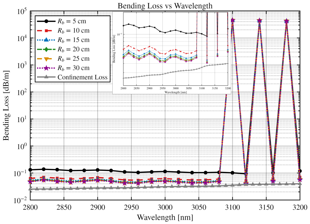
The bending characteristics of the fabricated-scale design are of major importance given the long operating wavelength and comparatively large core size since they determine to what extent the fiber can be used in practical mid-infrared beam-delivery applications. Figure 10 shows the bending-loss spectrum across 2800–3200 nm for bend radii ranging from 5 to 30 cm, together with the straight-fiber confinement loss for reference. For bend radii of 10 cm and tighter, narrow, extremely high-loss resonance peaks appear within the band, reflecting phase-matched coupling between the fundamental core mode and cladding or whispering-gallery-like modes under bending, a bend-loss signature qualitatively similar to that reported for other negative-curvature and anti-resonant hollow-core fibers [23,25,26]. For bend radii of 15 cm and larger, the bending loss remains close to the straight-fiber confinement loss across most of the band, indicating that the design tolerates moderate macrobending without substantial excess loss once the bend radius exceeds approximately 10–15 cm.
Figure 10.
Bending loss spectrum of the asymmetric HC-ARF for bend radii ranging from 5 to 30 cm, shown together with the straight-fiber confinement loss for reference. Inset: magnified view of the 2800–3200 nm band.
3.3. Geometrical Sensitivity and Fabrication Tolerance
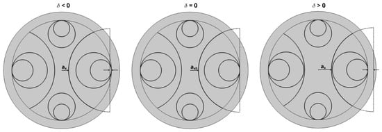
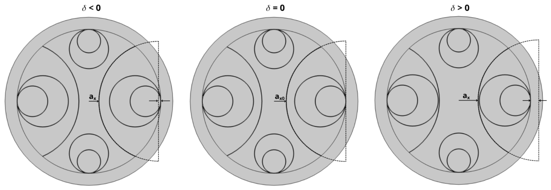
Having established the spectral behavior of the asymmetric design across the visible, near-infrared, and mid-infrared bands, we now examine how sensitive the flat-top condition is to deviations in the cladding geometry itself—a question of direct relevance to the fabrication tolerances required in practice. The core mechanism of the spatial reshaping is governed by a geometric asymmetry parameter , where is the nominal semi-axis of the elliptical core used in the numerical analysis of Section 3.1. This was implemented by shifting the center of the horizontal semicircular elements toward or away from its nominal position at , as shown in Figure 11.
Figure 11.
Schematic definition of the geometric asymmetry parameter . Negative corresponds to an inward displacement (over-squeezed core); is the nominal design; positive corresponds to an outward retraction (relaxed core).
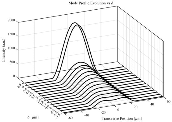
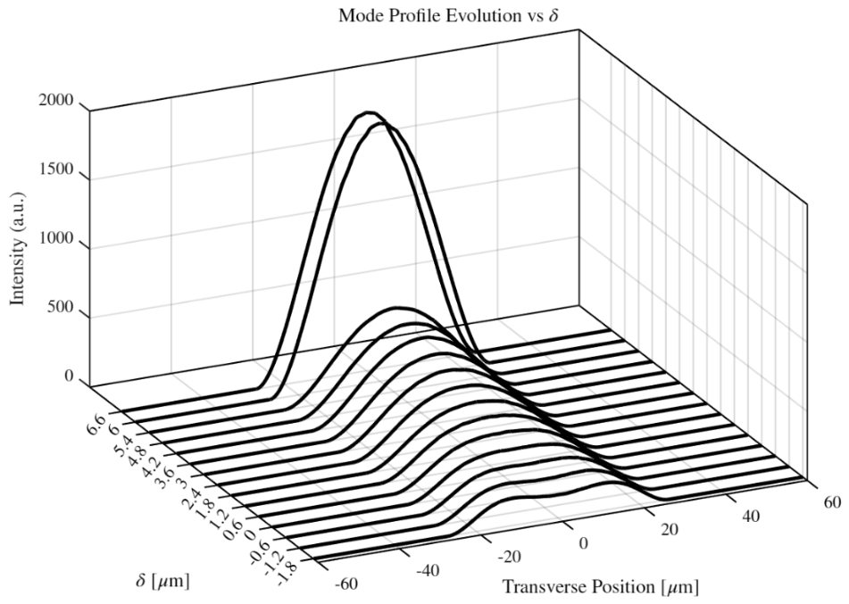
The evolution of the time-averaged power flow shown in Figure 12 demonstrates high sensitivity to this parameter: at the nominal condition (), the design recovers the ideal flat-top profile; for , an inward displacement of the semicircular cladding elements progressively compresses the guided mode, and as confinement tightens, the flat-top profile narrows and ultimately splits into two distinct lateral lobes, signaling the onset of a bimodal field distribution; for , retracting the cladding elements outward relaxes the lateral confinement, allowing the mode to expand into a broader, Gaussian-like distribution, accompanied by a nearly monotonic, roughly nine-fold increase in peak intensity (in arbitrary units) between and . This behavior quantifies the geometric tolerance necessary to preserve the top-hat profile and directly informs the fabrication precision required of the stack-and-draw process.
Figure 12.
Evolution of the time-averaged power flow profile (in arbitrary units) along the transverse axis as a function of the geometric asymmetry parameter , where is the nominal semi-axis of the elliptical core.
4. Discussion
Taken together, the results above show that a single, passive geometric modification—enlarging one pair of nested cladding capillaries relative to the orthogonal pair—produces a flat-top fundamental mode whose plateau width is essentially unchanged, to within a few percent, from the visible (577 nm) through the near-infrared (900–1600 nm) to the mid-infrared (3 μm), even though the underlying confinement loss varies by several orders of magnitude over the same range. This indicates that the shaping mechanism is primarily geometric in origin, set by the elliptical core boundary, a conclusion consistent with its persistence across the full waterfall representation of Figure 6.
Because the design also breaks the degeneracy between the x- and y-polarized fundamental modes, flat-top shaping is inherently polarization-selective: only the y-polarized mode develops the broad plateau, while the x-polarized mode remains comparatively narrow and centrally peaked at every wavelength examined (Figure 2, Figure 7 and Figure 8). This dual behavior, simultaneous beam shaping and polarization selection, follows directly from the same geometric asymmetry and does not require separate design elements for each function. It is worth noting that the semicircular-element geometry underlying this asymmetry has, to date, been employed almost exclusively to enhance birefringence and polarization extinction in HC-ARFs [31,32,35,36,37]; the present results indicate that the same structural family can be repurposed as a beam-shaping element, with polarization selectivity arising as an intrinsic, rather than targeted, byproduct.
The geometric sensitivity analysis of Section 3.3 is of direct relevance to fabrication because the flat-top condition exists only within a bounded window around , bordered by an over-squeezed, bimodal-splitting regime on one side and a progressively Gaussian, higher-peak-power regime on the other. The horizontal capillary spacing achieved during stack-and-draw fabrication must be controlled to a precision commensurate with the width of this window in order to reliably realize the reported flat-top behavior. Likewise, the bending-loss results indicate a practical minimum bend radius of order 10–15 cm for low-excess-loss operation in the mid-infrared band studied, below which narrow-band resonant coupling to cladding modes produces sharp loss peaks, consistent with bend-loss trends previously reported for other anti-resonant hollow-core geometries [25,26].
5. Conclusions
We have proposed and numerically validated an asymmetric hollow-core anti-resonant fiber design capable of flat-top beam shaping. The key finding of this work is that top-hat beam generation is achieved intrinsically through fiber geometry directly in the fundamental mode: by enlarging one pair of nested cladding capillaries relative to the orthogonal pair, we avoid the insertion loss and long-term instabilities associated with external beam shapers [4,6,7] or higher-order mode mixing [10,11]. In the near-infrared, the design gives a 104.8% top-hat beam expansion relative to a symmetric reference fiber at 1 μm, with a 90% plateau width that varies by less than 2.1% across the 900–1600 nm guidance band and a confinement loss approaching dB/m. The same shaping mechanism extends to the visible ( at 577 nm) and to the mid-infrared (, combined confinement-plus-material loss below 0.1 dB/m across 2700–3200 nm), and the reported bending loss is negligible for bend radii above approximately 10–15 cm. A parametric analysis of the geometric asymmetry parameter further establishes the fabrication tolerance within which the flat-top condition is preserved.
Author Contributions
Conceptualization, W.B.; methodology, A.A.E.S., D.R.P. and W.B.; software, A.A.E.S. and D.R.P.; validation, A.A.E.S., D.R.P. and W.B.; formal analysis, A.A.E.S. and D.R.P.; investigation, A.A.E.S., D.R.P. and W.B.; writing—original draft preparation, A.A.E.S.,D.R.P. and W.B.; writing—review and editing, W.B.; supervision, W.B. All authors have read and agreed to the published version of the manuscript.
Funding
This research received no external funding.
Data Availability Statement
The original contributions presented in this study are included in the article. Further inquiries can be directed to the corresponding author.
Conflicts of Interest
The authors declare no conflicts of interest.
References
- Clark, S.M.; Lobser, D.; Revelle, M.C.; Yale, C.G.; Bossert, D.; Burch, A.D.; Chow, M.N.; Hogle, C.W.; Ivory, M.; Pehr, J.; et al. Engineering the Quantum Scientific Computing Open User Testbed. IEEE Trans. Quantum Eng. 2021, 2, 3102832. [Google Scholar] [CrossRef] [Scilit]
- Ammenwerth, M.; Timme, H.; Giardini, V.; Tao, R.; Gyger, F.; Lib, O.; Berndt, D.; Kourkoulos, D.; Rom, T.; Bloch, I.; et al. Dynamical spatial light modulation in the ultraviolet spectral range. Phys. Rev. Appl. 2025, 24, 034031. [Google Scholar] [CrossRef] [Scilit]
- Frieden, B.R. Lossless conversion of a plane laser wave to a plane wave of uniform irradiance. Appl. Opt. 1965, 4, 1400–1403. [Google Scholar] [CrossRef] [Scilit]
- Dickey, F.M.; Holswade, S.C. (Eds.) Laser Beam Shaping: Theory and Techniques; Marcel Dekker: New York, NY, USA, 2000. [Google Scholar]
- Gerchberg, R.W.; Saxton, W.O. A practical algorithm for the determination of phase from image and diffraction plane pictures. Optik 1972, 35, 237–246. [Google Scholar]
- Liu, J.S.; Taghizadeh, M.R. Iterative algorithm for the design of diffractive phase elements for laser beam shaping. Opt. Lett. 2002, 27, 1463–1465. [Google Scholar] [CrossRef] [Scilit] [PubMed]
- Ma, H.; Zhao, H.; Zhou, P.; Wang, X.; Ma, Y.; Xu, X.; Liu, Z. Adaptive conversion of multimode beam to near-diffraction-limited flattop beam based on dual-phase-only liquid-crystal spatial light modulators. Opt. Express 2010, 18, 27723–27730. [Google Scholar] [CrossRef] [Scilit] [PubMed]
- Yu, X. Laser beam shaping based on liquid-crystal spatial light modulator. Acta Opt. Sin. 2012, 5, 0514001. [Google Scholar] [CrossRef] [Scilit]
- Nodop, D.; Ruecker, J.; Waechter, S.; Kahle, M. Hyperbolic phase function used in a spatial light modulator for flat top focus generation. Opt. Lett. 2019, 44, 2169–2172. [Google Scholar] [CrossRef] [Scilit] [PubMed]
- Xu, C.; Yan, K.; Gu, C.; Yao, P.; Xu, L.; Zhan, Q. All-fiber laser with flattop beam output using a few-mode fiber Bragg grating. Opt. Lett. 2018, 43, 1247–1250. [Google Scholar] [CrossRef] [Scilit] [PubMed]
- Zhu, H.; Fu, X.; Fan, S.; Liang, L.; Lin, X.; Ning, Y. The conversion from a Gaussian-like beam to a flat-top beam in the laser hardening processing using a fiber coupled diode laser source. Opt. Laser Technol. 2020, 125, 106028. [Google Scholar] [CrossRef] [Scilit]
- Kang, H.; Zhang, H.; Yan, P.; Wang, D.; Gong, M. Flat-topped beam output from a double-clad rectangular dielectric waveguide laser with a high-index inner cladding. Opt. Commun. 2009, 282, 2407–2412. [Google Scholar] [CrossRef] [Scilit]
- Kasztelanic, R.; Nguyen, H.T.; Pysz, D.; Thienpont, H.; Omatsu, T.; Buczynski, R. Free-Form Optical Fiber with a Square Mode and Top-Hat Intensity Distribution. Adv. Sci. 2024, 11, 2402886. [Google Scholar] [CrossRef] [Scilit] [PubMed]
- Lu, G.; Liu, S.; Lv, D.; Chen, M.; Zhang, Z. Design of photonic crystal fiber with large mode area for flat-top mode generation. Opt. Quantum Electron. 2023, 55, 143. [Google Scholar] [CrossRef] [Scilit]
- Gu, G.; Kong, F.; Hawkins, T.W.; Jones, M.; Dong, L. Extending mode areas of single-mode all-solid photonic bandgap fibers. Opt. Express 2015, 23, 9147–9156. [Google Scholar] [CrossRef] [Scilit] [PubMed]
- Marcatili, E.A.J.; Schmeltzer, R.A. Hollow metallic and dielectric waveguides for long distance optical transmission and lasers. Bell Syst. Tech. J. 1964, 43, 1783–1809. [Google Scholar] [CrossRef] [Scilit]
- Cregan, R.F.; Mangan, B.J.; Knight, J.C.; Birks, T.A.; Russell, P.S.J.; Roberts, P.J.; Allan, D.C. Single-mode photonic band gap guidance of light in air. Science 1999, 285, 1537–1539. [Google Scholar] [CrossRef] [Scilit] [PubMed]
- Benabid, F.; Knight, J.C.; Antonopoulos, G.; Russell, P.S.J. Stimulated Raman scattering in hydrogen-filled hollow-core photonic crystal fiber. Science 2002, 298, 399–402. [Google Scholar] [CrossRef] [Scilit] [PubMed]
- Litchinitser, N.M.; Abeeluck, A.K.; Headley, C.; Eggleton, B.J. Antiresonant reflecting photonic crystal optical waveguides. Opt. Lett. 2002, 27, 1592–1594. [Google Scholar] [CrossRef] [Scilit] [PubMed]
- Duguay, M.A.; Kokubun, Y.; Koch, T.L.; Pfeiffer, L. Antiresonant reflecting optical waveguides in SiO2-Si multilayer structures. Appl. Phys. Lett. 1986, 49, 13–15. [Google Scholar] [CrossRef] [Scilit]
- Pryamikov, A.D.; Biriukov, A.S.; Kosolapov, A.F.; Plotnichenko, V.G.; Semjonov, S.L.; Dianov, E.M. Demonstration of a waveguide regime for a silica hollow-core microstructured optical fiber with a negative curvature of the core boundary in the spectral region > 3.5 μm. Opt. Express 2011, 19, 1441–1448. [Google Scholar] [CrossRef] [Scilit] [PubMed]
- Yu, F.; Knight, J.C. Negative curvature hollow-core optical fiber. IEEE J. Sel. Top. Quantum Electron. 2016, 22, 146–155. [Google Scholar] [CrossRef] [Scilit]
- Wei, C.; Weiblen, R.J.; Menyuk, C.R.; Hu, J. Negative curvature fibers. Adv. Opt. Photonics 2017, 9, 504–561. [Google Scholar] [CrossRef] [Scilit]
- Belardi, W.; Knight, J.C. Hollow antiresonant fibers with reduced attenuation. Opt. Lett. 2014, 39, 1853–1856. [Google Scholar] [CrossRef] [Scilit] [PubMed]
- Kolyadin, A.N.; Kosolapov, A.F.; Pryamikov, A.D.; Biriukov, A.S.; Plotnichenko, V.G.; Dianov, E.M. Light transmission in negative curvature hollow core fiber in extremely high material loss region. Opt. Express 2013, 21, 9514–9519. [Google Scholar] [CrossRef] [Scilit] [PubMed]
- Belardi, W.; Knight, J.C. Hollow antiresonant fibers with low bending loss. Opt. Express 2014, 22, 10091–10096. [Google Scholar] [CrossRef] [Scilit] [PubMed]
- Sakr, H.; Chen, Y.; Jasion, G.T.; Bradley, T.D.; Hayes, J.R.; Mulvad, H.C.H.; Davidson, I.A.; Fokoua, E.N.; Poletti, F. Hollow core NANFs with five nested tubes and record low loss at 850, 1060, 1300 and 1625 nm. In Proceedings of the Optical Fiber Communication Conference (OFC), San Diego, CA, USA, 8–12 March 2020. [Google Scholar] [CrossRef] [Scilit]
- Jasion, G.T.; Bradley, T.D.; Harrington, K.; Sakr, H.; Chen, Y.; Fokoua, E.N.; Davidson, I.A.; Taranta, A.; Hayes, J.R.; Richardson, D.J.; et al. Hollow core NANF with 0.28 dB/km attenuation in the C and L bands. In Proceedings of the Optical Fiber Communication Conference (OFC), San Diego, CA, USA, 6–10 March 2022. [Google Scholar] [CrossRef] [Scilit]
- Gao, S.; Chen, H.; Xiong, Y.; Sun, Y.; Ding, W.; Wang, Y. 40 km, 0.052 dB/km and 83 km, 0.076 dB/km in Interstitial-Tube-Assisted Hollow-Core Fibre. In Proceedings of the European Conference on Optical Communication (ECOC), Copenhagen, Denmark, 28 September–2 October 2025; pp. 1–4. [Google Scholar] [CrossRef] [Scilit]
- Debord, B.; Amrani, F.; Vincetti, L.; Gérôme, F.; Benabid, F. Hollow-Core Fiber Technology: The Rising of “Gas Photonics”. Fibers 2019, 7, 16. [Google Scholar] [CrossRef] [Scilit]
- Hong, Y.F.; Gao, S.F.; Ding, W.; Zhang, X.; Jia, A.Q.; Sheng, Y.L.; Wang, P.; Wang, Y. Highly birefringent anti-resonant hollow-core fiber with a bi-thickness fourfold semi-tube structure. Laser Photonics Rev. 2022, 16, 2100365. [Google Scholar] [CrossRef] [Scilit]
- Hong, Y.F.; Jia, A.Q.; Gao, S.F.; Sheng, Y.; Lu, X.; Liang, Z.; Zhang, Z.; Ding, W.; Wang, Y. Birefringent, low loss, and broadband semi-tube anti-resonant hollow-core fiber. Opt. Lett. 2023, 48, 163–166. [Google Scholar] [CrossRef] [Scilit] [PubMed]
- Ding, W.; Wang, Y.Y. Hybrid transmission bands and large birefringence in hollow-core anti-resonant fibers. Opt. Express 2015, 23, 21165–21174. [Google Scholar] [CrossRef] [Scilit] [PubMed]
- Mousavi, S.A.; Sandoghchi, S.R.; Richardson, D.J.; Poletti, F. Broadband high birefringence and polarizing hollow core antiresonant fibers. Opt. Express 2016, 24, 22943–22958. [Google Scholar] [CrossRef] [Scilit] [PubMed]
- Li, Z.; Qin, Y.; Ren, J.; Huang, X.; Bao, Y. Design and Optimization of Polarization-Maintaining Low-Loss Hollow-Core Anti-Resonant Fibers Based on a Multi-Objective Genetic Algorithm. Photonics 2025, 12, 826. [Google Scholar] [CrossRef] [Scilit]
- Zong, L.; Cheng, J.; Xiao, Y. Design of Hollow-Core Anti-Resonant Fibers Supporting Few Weakly Coupled Polarization-Maintaining Modes. Photonics 2025, 12, 1018. [Google Scholar] [CrossRef] [Scilit]
- Hasan, M.M.S.; Alam, M.S.; Habib, M.S.; Islam, M.A. Cladding-Engineered Hollow-Core Fiber for Polarization Control and Optical Sensing Applications. IEEE Photonics J. 2026, 18, 2200608. [Google Scholar] [CrossRef] [Scilit]
- Saitoh, K.; Koshiba, M. Single-polarization single-mode photonic crystal fibers. IEEE Photon. Technol. Lett. 2003, 15, 1384–1386. [Google Scholar] [CrossRef] [Scilit]
- Xu, H.; Yang, Y.; Yuan, J.; Wu, D.; Huang, Y.; Luo, S.; Ren, Z.; Xia, C.; Liu, J.; Zhou, G.; et al. Low Loss and High Polarization-Maintaining Single-Mode Hollow-Core Anti-Resonant Fibers with S+C+L+U Communication Bands. Photonics 2025, 12, 846. [Google Scholar] [CrossRef] [Scilit]
- Belardi, W. Design and Properties of Hollow Antiresonant Fibers for the Visible and Near Infrared Spectral Range. J. Light. Technol. 2015, 33, 4497–4503. [Google Scholar] [CrossRef] [Scilit]

Disclaimer/Publisher’s Note: The statements, opinions and data contained in all publications are solely those of the individual author(s) and contributor(s) and not of MDPI and/or the editor(s). MDPI and/or the editor(s) disclaim responsibility for any injury to people or property resulting from any ideas, methods, instructions or products referred to in the content. |
© 2026 by the authors. Licensee MDPI, Basel, Switzerland. This article is an open access article distributed under the terms and conditions of the Creative Commons Attribution (CC BY) license.