


Highlights
What are the main findings?
- Prestressing effectively regulates cure-induced residual strain in CFRP laminates.
- Prestressing mode strongly affects fiber–matrix bonding and fracture behavior.
- Moderate prestress improves interfacial integrity and tensile performance.
What are the implications of the main findings?
- Embedded dual-FBG sensing enables in situ evaluation of strain evolution during curing.
- Combining axial tension with through-thickness compression improves stress regulation.
Abstract
Advanced composite materials have been widely applied in aerospace structures owing to their low weight, high strength, excellent fatigue resistance, and corrosion resistance. However, during the curing and molding processes of carbon-fiber composites, significant residual stresses are introduced within the components due to factors such as thermal contraction, resin curing shrinkage, and the mismatch in thermal expansion coefficients between the fibers and the matrix. This consequently compromises the performance and reliability of the composites, potentially leading to deformation, warpage, and even cracking, which in severe cases may result in component rejection. This paper aims to investigate the mechanisms by which different forms of prestress influence curing-induced residual stress and strain states, and to analyze their effects on the mechanical properties and microstructural evolution of the materials. In this study, embedded fiber Bragg grating sensors were used to monitor strain evolution during the heating, isothermal curing, and cooling stages of unidirectional carbon-fiber-reinforced polymer laminates subjected to no prestressing, uniaxial through-thickness compressive prestressing, or biaxial prestressing. Tensile tests and scanning electron microscopy were subsequently conducted to evaluate the mechanical response and fracture morphology. The fiber Bragg grating results showed that the strain response varied markedly with the prestressing mode and force level. The findings are expected to provide theoretical guidance and experimental references for mitigating curing-induced residual stresses and improving the molding quality of composite materials.
1. Introduction
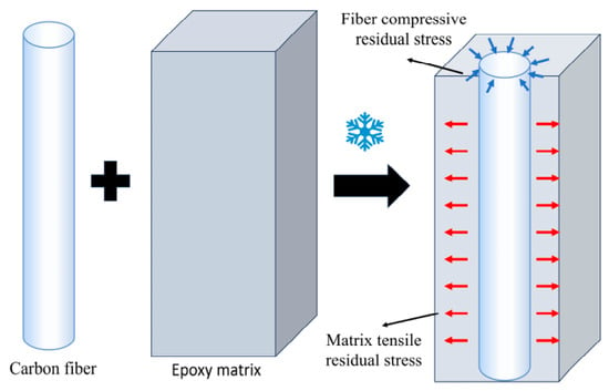
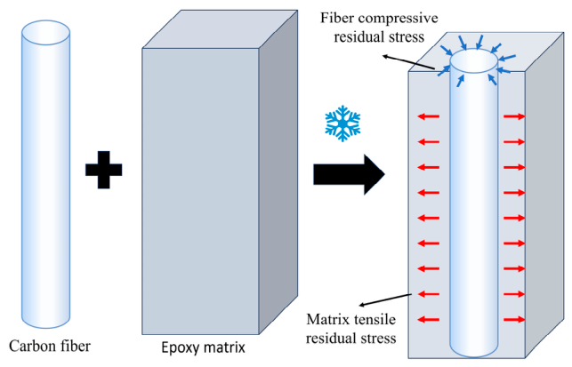
Carbon-fiber-reinforced polymer (CFRP) composites offer high specific strength, high specific stiffness, and good processability. They are therefore widely used in aerospace and automotive applications [1,2]. During curing, however, CFRP composites undergo complex thermophysical and thermochemical changes. Cure-induced residual stresses mainly originate from resin curing shrinkage and the mismatch in the coefficients of thermal expansion between the carbon fibers and epoxy matrix. As seen in Figure 1, intra-ply microscopic residual stresses form mostly between the fibers and the matrix.
Figure 1.
Schematic illustration of the formation of microresidual stress. The blue and red arrows indicate fiber compressive residual stress and matrix tensile residual stress, respectively.
During curing, CFRP composites undergo complex thermophysical and thermochemical changes. Cure-induced residual stresses mainly originate from resin curing shrinkage and the mismatch in the coefficients of thermal expansion between the carbon fibers and the epoxy matrix. As schematically illustrated in Figure 1, during cooling from the curing temperature, the epoxy matrix undergoes greater thermal contraction than the carbon fibers. Because the fiber and matrix are bonded together, their free thermal contraction is mutually constrained at the interface. Consequently, tensile residual stress develops in the epoxy matrix, whereas the carbon fibers are mainly subjected to compressive residual stress [3,4,5,6].
The thermal residual stresses generated during cooling can be described using micromechanical thermoelastic models in which the stress state is governed by the mismatch in the coefficients of thermal expansion between the fiber and the matrix, the temperature change, the elastic properties of the constituents, and the fiber volume fraction. Composite-cylinder-based formulations have been developed to estimate the three-dimensional residual stress state in the fiber and matrix of unidirectional composites [7].
These residual stresses can result in macroscopic defects, including warpage, deformation, and delamination, and may also contribute to matrix microcracking, fiber fracture, and interfacial debonding. Because carbon fibers and the polymer matrix have markedly different coefficients of thermal expansion, the internal stress state may continue to vary when the cured composite experiences subsequent temperature changes. Residual stress is also relevant to cyclic damage because it modifies the initial local stress state from which fatigue loading proceeds. Therefore, controlling cure-induced residual stress is important not only for dimensional stability and static mechanical performance but also for the long-term structural reliability of CFRP composites [8,9,10].
Research on prestressed composites has focused on residual-stress control, mechanical-property enhancement, damage evolution, and cure-deformation control. Residual stresses strongly affect fiber-matrix debonding, fiber pull-out, matrix cracking, and dimensional stability. Appropriate residual compressive stress can suppress crack propagation and improve fracture resistance and fatigue life. During the curing process, fiber prestressing adds a tensile preload to the reinforcement. Following release, the fibers transfer compressive stress to the matrix and thereby reduce tensile residual stress [11,12,13].
Prestressed composites have been the subject of comparatively early international research that has grown into a systematic discipline. Reported approaches include elastic and viscoelastic prestressing [14,15], dead-weight loading, V-groove loading, filament winding, hydraulic loading, and biaxial loading [16,17,18,19,20]. Mechanical testing, strain monitoring, and scanning electron microscopy (SEM) have been used to examine impact, flexural, and fatigue behavior, together with interfacial failure [21,22,23,24,25].
Studies in China have focused more on the formation of residual stress and cure deformation, together with their mitigation by prestressing. According to current research, mismatched coefficients of thermal expansion and resin curing shrinkage can cause residual stresses and deformation to develop within laminates during the curing and cooling stages. Nevertheless, applying prestress within a reasonable range can compensate for strain differences between different directions or layers, reducing curing deformation and improving molding accuracy [9,10,26,27,28,29,30,31,32].
Overall, prestressing shows promise for regulating residual stress, strengthening interfacial bonding, and improving the mechanical properties of CFRP composites. However, the effects of loading direction and force level on cure-induced strain evolution, interfacial damage, and final mechanical performance remain insufficiently understood, and the relationship between the prestressing level and residual stress release requires further clarification. Therefore, in situ monitoring of the curing process using fiber Bragg grating (FBG) sensors provides a useful means of examining cure-induced strain evolution in prestressed carbon-fiber composites [33], and analyzing the effects of different prestressing methods on residual stress, mechanical properties, and microstructural failure morphology holds significant research value.
In this study, the primary objective was to clarify how prestressing mode and load level affect cure-induced internal strain evolution in unidirectional carbon-fiber-reinforced polymer laminates and how these changes are associated with the subsequent tensile response and fracture morphology. Embedded fiber Bragg grating sensors were used for in situ monitoring throughout the prescribed curing cycle, while tensile testing and fracture-surface observations were performed after curing. By comparing unprestressed laminates, laminates subjected to uniaxial through-thickness compressive prestressing, and laminates subjected to combined fiber-direction tensile and through-thickness compressive prestressing, the study establishes an experimental relationship among prestressing condition, cure-induced strain evolution, tensile response, and interfacial fracture characteristics.
2. Materials and Methods
2.1. Materials, Experimental Equipment, and FBG Monitoring System
The laminates investigated in this study were fabricated from a unidirectional carbon-fiber/epoxy prepreg supplied by Wetech (Shanghai, China) Composite Materials Co., Ltd., China. The reinforcement was Torayca T700SC-12K carbon fiber (Toray Industries, Inc., Tokyo, Japan) with an average filament diameter of approximately 7.5 μm, and the matrix was a medium-temperature-curing toughened epoxy resin system with a glass-transition temperature of approximately 120 °C. The prepreg roll used in the experiments was identified as model 15001 and batch No. 121030431. The material label specified a resin content of 33 wt%, corresponding to a fiber volume fraction of approximately 57%. Before lay-up, the prepreg was removed from frozen storage and allowed to equilibrate at room temperature for 24 h before use to minimize moisture condensation.
The principal experimental equipment is listed in Table 1.
Table 1.
Key experimental instruments.
A dual-FBG sensing configuration was employed for simultaneous temperature and strain monitoring during curing. Two FBG sensors with different initial Bragg wavelengths were embedded between the third and fourth plies of the six-ply laminate. One bare FBG was directly coupled with the surrounding prepreg, and therefore responded to both temperature and mechanical strain. The second FBG was encapsulated in a thin stainless-steel tube to isolate the grating region from mechanical loading and was used as the temperature-reference sensor. Because the two sensors were positioned in the same interlaminar region, they experienced approximately the same temperature history.
The wavelength shift of the bare FBG can be expressed as:
where is the wavelength shift measured by the bare FBG, is the strain sensitivity coefficient, is the mechanical strain, and is the temperature sensitivity coefficient. In the present sensing system, the temperature and strain sensitivity coefficients are approximately and , respectively, and is the temperature change. For the encapsulated temperature-reference FBG, the mechanical strain contribution is effectively isolated, and its wavelength shift is mainly caused by temperature:
Therefore, the strain-related wavelength variation can be obtained after temperature compensation, and the corresponding strain is calculated as:
Prior to the curing experiments, the temperature and strain sensitivity coefficients of the FBG sensors were experimentally calibrated. For temperature calibration, the FBG grating section was encapsulated in a stainless-steel tube to isolate it from external mechanical loading and was placed in the curing oven. The Bragg wavelength was recorded after the temperature stabilized at each prescribed temperature level, and the temperature sensitivity coefficient was determined from the slope of the linear relationship between Bragg wavelength shift and temperature change. For strain calibration, FBG sensors were embedded between the third and fourth plies of a six-ply unidirectional CFRP laminate. After curing, the specimens were subjected to uniaxial tensile loading at a constant crosshead speed of 1 mm/min, while the Bragg wavelength shift was continuously recorded. The strain sensitivity coefficient was then obtained from the linear relationship between Bragg wavelength shift and applied strain. The calibrated coefficients, , , were subsequently used for temperature compensation and strain calculation during curing.
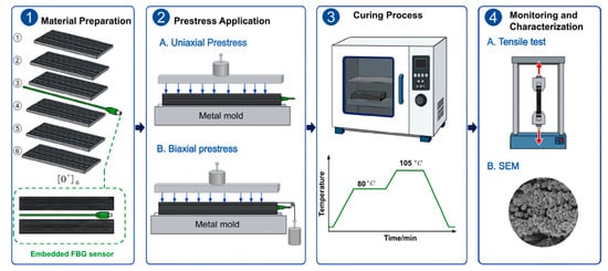
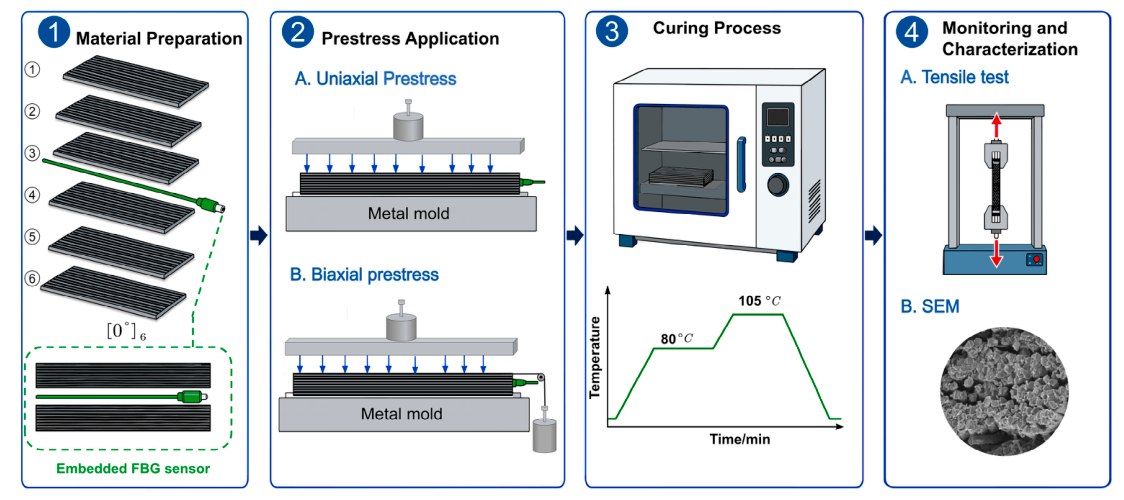
Figure 2 summarizes the fabrication, cure monitoring, and performance characterization workflow for the prestressed laminates. The procedure comprised four stages. Stage 1 involved material preparation, including lay-up and FBG-sensor embedding. Stage 2 involved the application of uniaxial or biaxial prestress. Stage 3 comprised heating, isothermal curing, and cooling. Stage 4 comprised FBG monitoring, tensile testing, and SEM analysis of mechanical performance and microstructural evolution.
Figure 2.
Experimental workflow for fabrication, FBG monitoring, and characterization of prestressed CFRP laminates.
2.2. Prestressed Forming of CFRP Composites
All CFRP specimens were fabricated from six plies of unidirectional carbon-fiber/epoxy prepreg, with a final laminate thickness of approximately 1 mm. The prepreg was cut into 500 mm × 30 mm strips. The mold surface was cleaned with acetone and uniformly coated with poly (vinyl alcohol) (PVA) release agent, which was allowed to air-dry for 15 min before lay-up. Six prepreg plies were then stacked sequentially with all fibers aligned along the longitudinal direction of the specimen, resulting in a stacking sequence. During lay-up, each newly placed ply was carefully consolidated to remove visibly entrapped air and maintain uniform interlaminar contact. The same lay-up, consolidation, curing, and cooling procedures were used for all prestressing groups. Two FBG sensors (AG-1562-90.0-0.25-15-SH, Shandong Shenghai Optical Fiber Technology Co., Ltd., Tai’an, China) were embedded between the third and fourth plies, corresponding approximately to the laminate mid-plane, for simultaneous temperature and strain monitoring during curing.
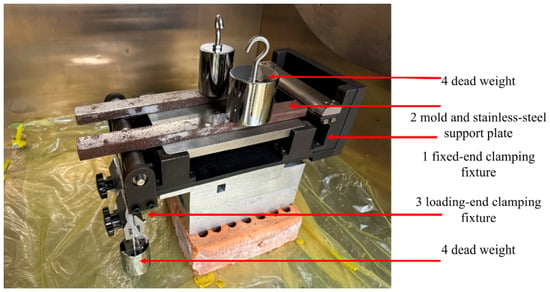
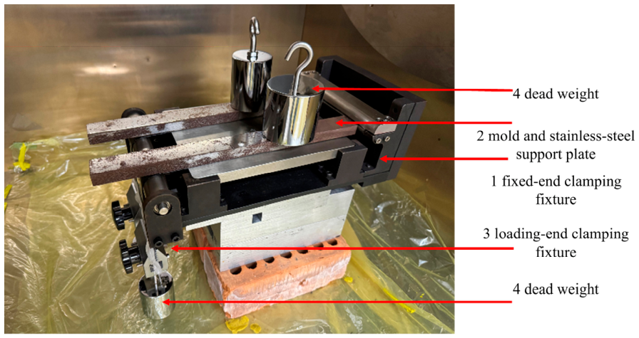
To achieve stable clamping of the CFRP prepreg and to enable the application of different prestressing modes, the prestressed forming device shown in Figure 3 was used. The device mainly consisted of a fixed-end clamping fixture (1), a mold and stainless-steel support plate (2), a loading-end clamping fixture (3), and dead weights (4). The mold and stainless-steel support plate supported the laminate and maintained its flatness during lay-up and curing. The fixed-end clamping fixture constrained one end of the laminate, whereas the loading-end clamping fixture secured the opposite end and transferred the externally applied tensile load. The clamping components and support plate in direct contact with the prepreg were made of stainless steel to facilitate demolding after curing.
Figure 3.
Photograph of the specimen with biaxial prestress applied before curing.
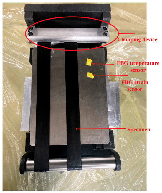
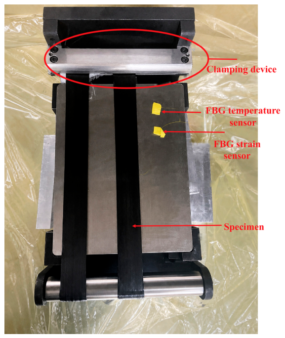
Both ends of the laminate were secured using clamping fixtures. Each fixture consisted of upper and lower clamping components that were tightened using bolts. To reduce local stress concentration in the clamping region, the prepreg end was placed in contact with the curved surface of the lower clamping component before tightening. During installation, the prepreg was first aligned with the centerline of the fixture, after which the upper clamping component was positioned and the bolts were tightened to secure the laminate. After completion of the lay-up and FBG-sensor placement, one end of the laminate was fixed by the fixed-end clamping fixture (1), while the opposite end was secured by the loading-end clamping fixture (3), thereby providing the required boundary constraints for subsequent prestress application. Figure 4 provides a top view of the experimental setup. The CFRP prepreg specimen is positioned on the stainless-steel support plate and secured by the clamping fixture. The locations of the FBG strain sensor and the temperature-reference FBG sensor are also indicated.
Figure 4.
Top view of the CFRP prepreg specimen and FBG sensor arrangement in the prestressing device before curing.
Two prestressing modes were investigated in this study: uniaxial prestressing and biaxial prestressing. For the uniaxially prestressed specimens, dead weights were applied through the upper loading structure. The gravitational load generated by the dead weights was transferred to the laminate surface, producing a sustained compressive load in the through-thickness direction. Different uniaxial prestressing force levels were obtained by changing the applied dead weights.
For the biaxially prestressed specimens, a tensile load was additionally applied along the carbon-fiber direction while the through-thickness compressive load was maintained. A second set of dead weights acted through the loading-end clamping fixture, while the fixed-end clamping fixture constrained the opposite end of the laminate. Therefore, the biaxial prestressing condition consisted of the simultaneous application of fiber-direction tensile loading and through-thickness compressive loading.
2.3. Curing Schedule
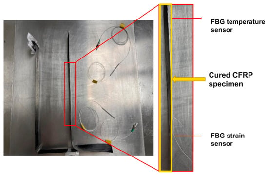
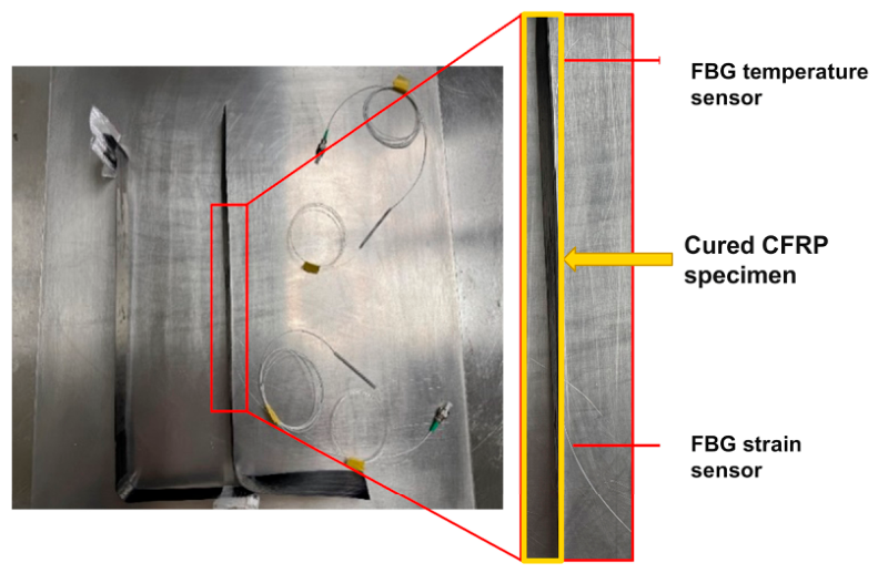
The prepared composite panels were placed in a curing oven. The temperature was increased from room temperature to 80 °C at 3 °C min−1 and held for 1 h. It was then increased to 105 °C at the same rate and held for 2 h. The panels were subsequently cooled gradually to room temperature. Figure 5 shows a specimen after curing and demolding, with the region containing the embedded FBG sensor enlarged.
Figure 5.
Appearance of the specimen fabricated under biaxial prestressing after curing and demolding.
2.4. Tensile Testing
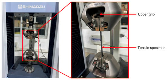
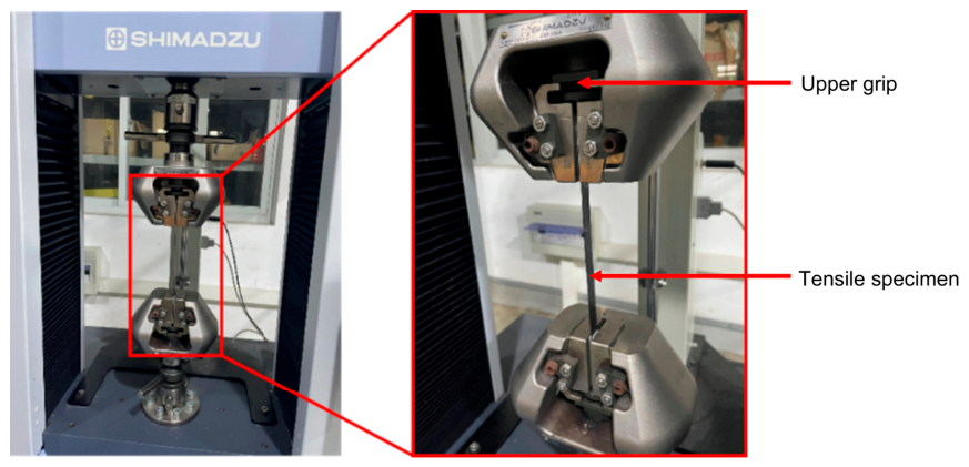
Cured CFRP laminates were subjected to tensile testing using a universal testing machine (AGS-X) in accordance with GB/T 3354-2014 [34]. Three replicate specimens were tested for each prestressing condition. Before testing, all specimens were allowed to equilibrate at the same laboratory ambient temperature, and all tensile tests were subsequently conducted under the same ambient-temperature condition. Aluminum-alloy tabs were bonded to the gripping sections of the specimens, and the tests were performed after the adhesive had fully cured. The crosshead speed was maintained at 1 mm min−1, and the load–displacement data were recorded at 1 s intervals. The tensile-testing setup and the enlarged specimen-gripping region are shown in Figure 6.
Figure 6.
Photograph of the tensile testing process.
All specimens were allowed to equilibrate to the same laboratory ambient temperature before tensile testing, and all tensile tests were conducted under the same ambient-temperature condition.
3. Results and Discussion
3.1. Evolution of Cure-Induced Residual Strain Monitored by FBG Sensors
FBG sensors were embedded in the laminates to monitor internal strain evolution during curing.
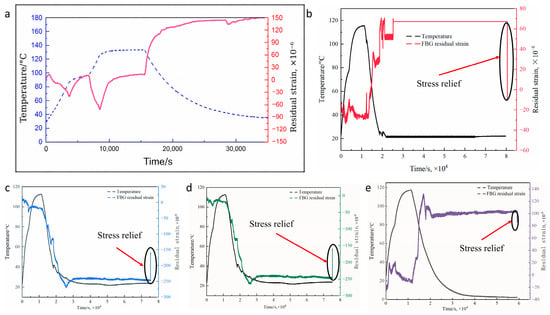
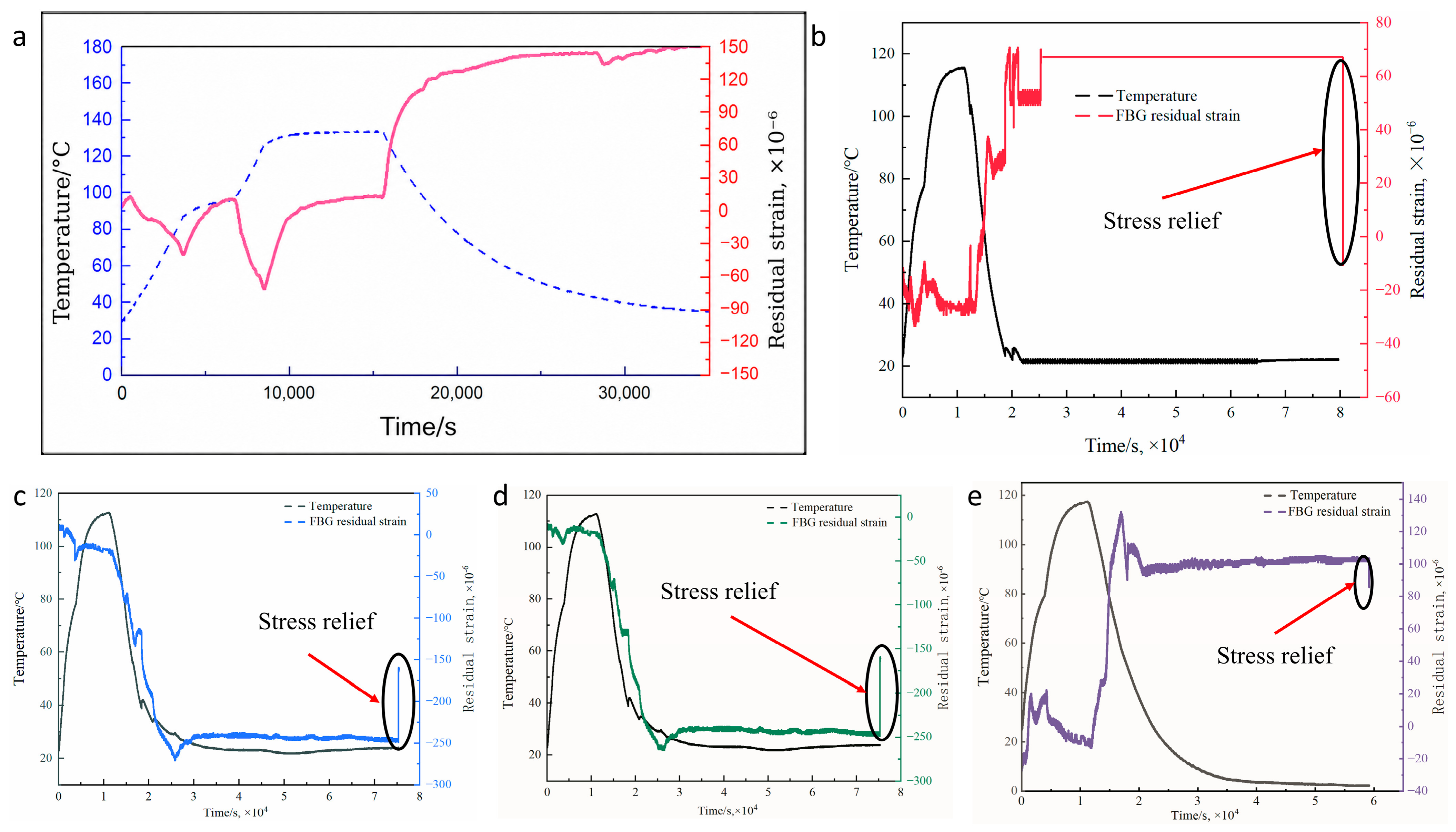
Temperature and residual strain were measured in situ without prestress and under uniaxial or biaxial prestress. Figure 7 presents their evolution during curing under the different prestress conditions.
Figure 7.
Evolution of temperature and FBG-monitored residual strain during curing of carbon-fiber composite laminates under different prestressing conditions: (a) no prestress; uniaxial prestressing at (b) 9.0 N, (c) 12.6 N, and (d) 13.9 N; and (e) biaxial prestressing at 21.8 N/33.5 N.
As shown in Figure 7a, the resin matrix transformed from a viscous-flow state toward a glassy state as curing temperature increased. Continued crosslinking caused chemical volume shrinkage. Meanwhile, the resin and reinforcing fibers developed a progressively stronger interface and began to carry load as an integrated system. The measured strain consequently approached a stable value. During cooling, thermal contraction became dominant. The different contraction of the fibers and matrix generated residual stress because of their thermal-expansion mismatch.
Figure 7b–d show the temperature and residual-strain histories during curing under uniaxial prestressing forces of 9, 12.6, and 13.9 N, respectively.
The residual-strain curves exhibited a characteristic multistage response governed by the temperature history and timing of external loading. During initial heating, the low-viscosity resin remained mobile, causing fluctuations in the residual-strain signal. As the temperature approached the gel point, resin viscosity increased rapidly and the structure gradually solidified. Under a 9 N prestressing force (Figure 7b), constrained internal-stress release produced a pronounced increase in residual strain.
At the higher prestressing force of 13.9 N (Figure 7d), residual strain decreased overall. This behavior indicates that the higher prestressing force promoted earlier strain accumulation and locking during curing. Under coupled thermal and mechanical loading, the system progressively lost elastic recovery capacity and released less strain.
Figure 7e shows the temperature and residual-strain histories during curing under biaxial prestress. Both curves exhibited distinct stages. During heating, resin viscosity decreased, and thermal-expansion mismatch between the fibers and resin caused small strain fluctuations. Near the gel point, the resin transformed from a viscous-flow state toward an elastic state, while crosslinking accelerated. The combined effects of chemical shrinkage and thermal expansion then caused a rapid strain increase.
During the high-temperature curing stage, continued resin crosslinking and thermal expansion/contraction effects contributed simultaneously to the measured strain response. During cooling, thermal-expansion mismatch placed the constrained fibers in tension while the matrix contracted. The interfacial stress then stabilized, and the residual-strain curve approached a plateau. Partial release of the initially applied tensile prestress caused the final slight decrease or fluctuation.
Overall, uniaxial and biaxial prestressing reduced the peak residual strain during curing and improved stress distribution and structural stability.
3.2. Effect of Prestress on the Mechanical Properties of CFRP Composites
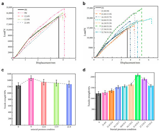
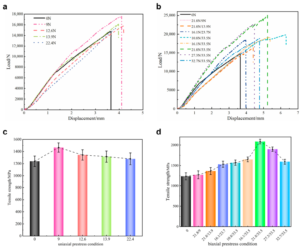
Tensile tests were conducted to determine how prestress affected the mechanical properties of the cured laminates. Figure 8 shows the tensile load–displacement curves under uniaxial and biaxial prestress. Figure 8a compares uniaxial prestressing forces of 0, 9, 12.6, 13.9, and 22.4 N. Figure 8b compares tangential/normal prestress combinations and their effects on load capacity and displacement at failure. Tensile strength was calculated from the load–displacement curves as follows:
where is the tensile strength, is the maximum load on the tensile curve, b is the effective specimen width (b = 12.5 mm), and h is the specimen thickness (h = 1 mm).
Figure 8.
Tensile responses of CFRP laminates under different prestressing conditions: (a) load–displacement curves under uniaxial prestress; (b) load–displacement curves under biaxial prestress; (c) tensile strength under uniaxial prestress; (d) tensile strength under biaxial prestress.
As shown in Figure 8a,c, all specimens initially exhibited an approximately linear load–displacement response. Damage then accumulated progressively until final failure. Peak load and failure displacement varied substantially with uniaxial prestress. At 9 N, the curve shifted upward and failure displacement increased to approximately 4.1 mm. The mean tensile strength reached approximately 1467 MPa, representing an increase of approximately 22.2% relative to the unprestressed condition. At 12.6 and 13.9 N, the peak loads remained above or close to the unstressed value. This result indicates that moderate through-thickness compressive constraint still provided reinforcement. At 22.4 N, both peak load and failure displacement decreased. Excessive through-thickness pressure may have promoted resin squeeze-out, local fiber-bundle disturbance, or restricted cure shrinkage. These effects could create new interfacial stress concentrations and offset the benefits of prestress-assisted consolidation.
The differences among the biaxially prestressed specimens were more pronounced (Figure 8b,d). Most combinations increased the peak load and shifted the failure displacement to the right relative to the unstressed specimen. Biaxial prestressing therefore improved both ultimate load capacity and tensile deformability. The 21.8 N/33.5 N condition produced the highest response, with a failure displacement of approximately 5.2 mm. Its tensile strength reached 2086 MPa, approximately 29.7% higher than that of the unstressed specimen. This combination appeared to balance fiber-direction tension and through-thickness consolidation effectively.
By contrast, combinations with lower through-thickness constraint, including 21.8 N/9 N and 21.8 N/13.9 N, produced peak loads of approximately 15 kN. Their improvement was limited, possibly because insufficient through-thickness consolidation failed to suppress voids, microdebonding, and locally loose fiber-matrix regions. The 27.3 N/33.5 N and 32.7 N/33.5 N conditions retained relatively high load capacities, but their peak strengths did not increase further. Excessive fiber-direction tensile prestress may have caused nonuniform local fiber tension or residual tensile-stress accumulation during curing. Cracks could then propagate more readily along weak interfacial regions during tensile loading. Thus, the reinforcing effect of biaxial prestress was nonmonotonic and showed an optimum matching range.
In summary, moderate prestress improved deformation compatibility between the fibers and matrix. It also promoted residual-strain release during curing, thereby reducing internal residual stress. The lower residual stress decreased stress concentrations and the risk of interfacial damage. These effects ultimately increased tensile strength and improved overall mechanical performance.
3.3. Effects of Different Prestress Modes on the Microstructure of CFRP Composites
The fracture interfaces of the tensile-tested laminates were examined systematically by SEM. The analysis focused on defect distribution and crack-propagation paths at the carbon-fiber/epoxy-matrix interface under different prestress conditions.
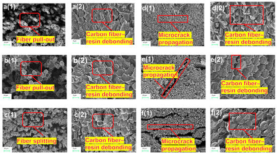
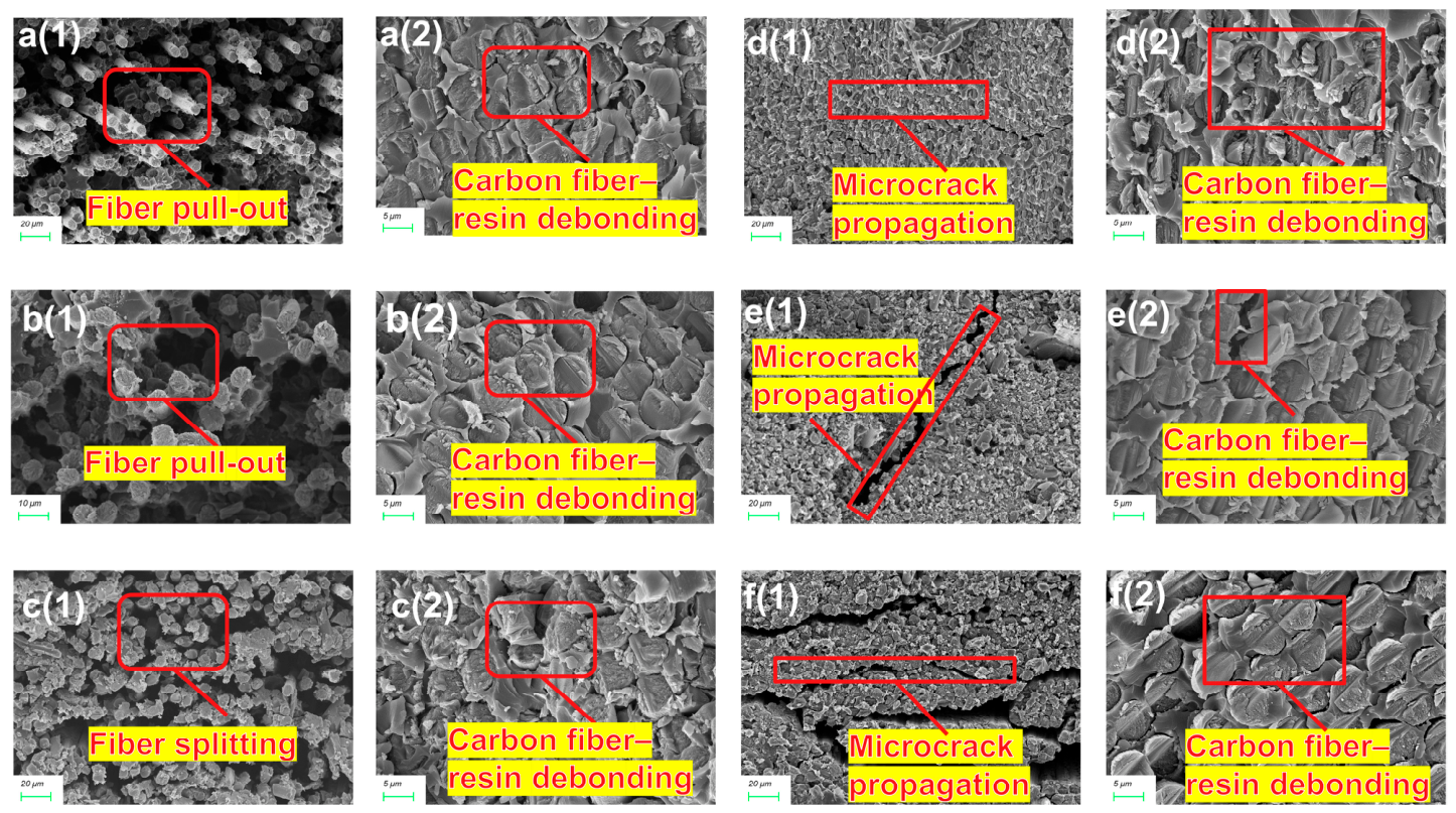
Figure 9a–c show the fracture-surface morphology under uniaxial prestress, including the tensile fracture surfaces and interfacial microstructures.
Figure 9.
SEM images of CFRP fracture surfaces under different prestress conditions: (a1) fiber pull-out and (a2) carbon fiber–resin debonding under 9 N uniaxial prestress; (b1) fiber pull-out and (b2) carbon fiber–resin debonding under 12.6 N uniaxial prestress; (c1) fiber splitting and (c2) carbon fiber–resin debonding under 13.9 N uniaxial prestress; (d1) microcrack propagation and (d2) carbon fiber–resin debonding under 21.8 N/33.5 N biaxial prestress; (e1) microcrack propagation and (e2) carbon fiber–resin debonding under 21.8 N/13.9 N biaxial prestress; (f1) microcrack propagation and (f2) carbon fiber–resin debonding under 21.8 N/9 N biaxial prestress.
At 9 N, the fiber-matrix interface still contained some fiber debonding and void defects. These defects were less extensive than those observed at 12.6 and 13.9 N, indicating stronger interfacial bonding. Under an appropriate prestress, the resin matrix coated the fibers and formed a continuous load-transfer interface. This morphology indicates strong bonding between the fibers and matrix. At 13.9 N, the fractured fibers carried only fragmented resin showing brittle-matrix fracture. Excessive prestress therefore appeared to promote interfacial stress concentration and microcrack propagation. These processes weakened effective fiber-matrix bonding and reduced the stability of the overall mechanical response. Resin residues nevertheless remained on some pulled-out fibers, indicating locally strong adhesion.
The different matrix responses arose from the combined effects of crosslink density and interfacial bonding. Moderate prestress improved interfacial quality and promoted orderly load transfer along the fibers. Excessive prestress caused interfacial stress concentrations. Once the local stress exceeded the fiber strength, fibers fractured and the released strain energy promoted brittle matrix fracture. The matrix then lost its continuous load-bearing capacity.
Figure 9d–f show representative fracture-surface morphologies under biaxial prestress, including the tensile fracture surfaces and interfacial microstructures.
Comparison of the interfacial microstructures showed fewer inter-fiber cracks as prestress increased. Crack paths also shortened, interfacial defects decreased, and fiber-matrix adhesion improved. Some nonuniform fracture nevertheless remained during tensile loading.
During heating, prestress can produce local compression at fiber ends and interfacial regions. This constraint limits resin shrinkage and reduces voids and microcracks caused by coupled thermal strain and chemical shrinkage. Resin-rich regions or nonuniform fiber arrangements may nevertheless remain where resin content is high or fiber distribution is sparse. These features are mainly associated with fiber volume fraction and loading uniformity. The biaxial prestressing condition combined fiber-direction tensile loading with through-thickness compression, thereby modifying both axial load transfer and through-thickness consolidation during curing. It can therefore improve microscale resin flow and cure-stress distribution. The resulting interface is denser, more continuous, and has fewer obvious defects.
The microstructures produced by uniaxial and biaxial prestress show that loading direction affects interfacial bonding and the spatial distribution of fibers and resin.
Comparison of the overall fracture morphologies under uniaxial and biaxial prestress is shown in Figure 9. Biaxially prestressed specimens generally contained two distinct regions: a fiber tensile-fracture region and a bonded fiber-matrix region. Their clear boundary indicates different degrees of interfacial stress concentration under combined external loading and cure shrinkage. Fine cracks were common under biaxial prestress. They were associated with high fiber-direction tension and cracking at the bonded interface. Under uniaxial prestress, load transfer occurred mainly through the thickness. Fiber ends showed a dispersed-filament morphology, indicating predominantly pull-out-type interfacial separation. Through-thickness compression therefore reduced the tendency for tensile failure along the fibers and improved fiber-matrix deformation compatibility.
Mechanistically, biaxial prestress generated a directional stress field at the fiber-matrix interface during curing. It promoted local resin shear slip and microcrack initiation, producing fracture regions with clear boundaries. Uniaxial prestress instead constrained the laminate through its thickness. It suppressed excessive resin flow and interfacial cracking, producing a more compliant, dispersed-filament fracture morphology. Biaxial prestress combined tangential and normal constraint, stabilized the interface, and restricted crack propagation. It therefore provided superior interfacial toughness and fracture resistance.
4. Conclusions
- Uniaxial prestress improved resin flow and interfacial bonding during curing within an appropriate loading range. Biaxial prestress combined the effects of fiber-direction tensile and through-thickness compressive loading. The two modes increased tensile strength by 22.2% and 29.7%, respectively. Appropriate prestressing dynamically regulated residual stress during curing and improved the overall performance reliability of the composites.
- SEM observations showed that uniaxial prestress suppressed excessive resin flow and interfacial cracking through compressive through-thickness constraint. The resulting fracture surfaces exhibited a more compliant, dispersed-filament morphology. Biaxial prestress combined both loading modes, producing a denser and more uniform interface. It also restricted crack propagation and improved interfacial toughness and overall load-bearing performance.
- Appropriate prestress improved fiber-matrix bonding, as indicated by resin residues, fiber fracture, and effective load transfer on the fracture surfaces. Under excessive prestress, fiber pull-out, filament separation, interfacial debonding, and microcracking became more pronounced.
Author Contributions
Conceptualization, X.L.; methodology, X.L. and H.T.; data curation, M.X. and P.W.; validation, M.X. and X.L.; formal analysis, P.W.; investigation, M.X. and P.W.; resources, X.L. and H.T.; data curation, M.X. and P.W.; writing—original draft preparation, X.L. and P.W.; writing—review and editing, M.X. and X.L.; visualization, M.X.; supervision, X.L. and H.T.; project administration, H.T.; funding acquisition, X.L. and H.T. All authors have read and agreed to the published version of the manuscript.
Funding
This research received no external funding.
Institutional Review Board Statement
Not applicable.
Informed Consent Statement
Not applicable.
Data Availability Statement
The original contributions presented in the study are included in the article; further inquiries can be directed to the corresponding author.
Acknowledgments
During the preparation of this manuscript, the authors used ChatGPT (OpenAI; model version: GPT-5.6) for English language polishing and suggestions regarding schematic figure layout. All figures were subsequently reviewed and finalized by the authors. The authors take full responsibility for the content of this publication.
Conflicts of Interest
The authors declare no conflicts of interest.
Abbreviations
| CFRP | Carbon-Fiber-Reinforced Polymer |
| FBG | Fiber Bragg Grating |
| SEM | Scanning Electron Microscopy |
| PVA | Polyvinyl Alcohol |
References
- Mrázová, M. Advanced composite materials of the future in aerospace industry. INCAS Bull. 2013, 5, 139–150. [Google Scholar] [CrossRef] [Scilit]
- Zhang, J.; Lin, G.; Vaidya, U.; Wang, H. Past, present and future prospective of global carbon fibre composite developments and applications. Compos. Part B Eng. 2023, 250, 110463. [Google Scholar] [CrossRef] [Scilit]
- Antonucci, V.; Cusano, A.; Giordano, M.; Nasser, J.; Nicolais, L. Cure-induced residual strain build-up in a thermoset resin. Compos. Part A Appl. Sci. Manuf. 2006, 37, 592–601. [Google Scholar] [CrossRef] [Scilit]
- Li, W.; Lee, L.J. Shrinkage control of low-profile unsaturated polyester resins cured at low temperature. Polymer 1998, 39, 5677–5687. [Google Scholar] [CrossRef] [Scilit]
- Parlevliet, P.P.; Bersee, H.E.N.; Beukers, A. Residual stresses in thermoplastic composites—A study of the literature—Part I: Formation of residual stresses. Compos. Part A Appl. Sci. Manuf. 2006, 37, 1847–1857. [Google Scholar] [CrossRef] [Scilit]
- Xing, J.B. Macroscopic and Microscopic Cure-Induced Residual Stress and Damage-Fracture Behavior of Carbon-Fiber-Reinforced Composites. Master’s Thesis, Qingdao University of Technology, Qingdao, China, 2024. Available online: https://d.wanfangdata.com.cn/thesis/D03518590 (accessed on 31 August 2026). (In Chinese)
- Barsanescu, P.D.; Grimberg, R.; Carlescu, P. Generation of Residual Stresses in Composites. In Proceedings of the 9th Biennial ASME Conference on Engineering Systems Design and Analysis (ESDA2008), Haifa, Israel, 7–9 July 2008; ASME: New York, NY, USA, 2009; Volume 1, pp. 623–628. [Google Scholar] [CrossRef] [Scilit]
- Barnes, J.A.; Byerly, G.E. The formation of residual stresses in laminated thermoplastic composites. Compos. Sci. Technol. 1994, 51, 479–494. [Google Scholar] [CrossRef] [Scilit]
- Xue, J.; Wang, X.J.; Wang, X.Z.; Shen, Z. Research status of evaluation methods for curing residual stress of carbon fiber reinforced resin matrix composites. J. Solid Rocket Technol. 2023, 46, 253–262. (In Chinese) [Google Scholar] [CrossRef]
- He, L.; Zhu, P.X.; Xu, X.W.; Wang, J.Y. A review on mechanism and control methods of residual stress and cured deformation of composite materials. Compos. Sci. Eng. 2022, 7, 121–128. (In Chinese) [Google Scholar] [CrossRef]
- Daynes, S.; Diaconu, C.G.; Potter, K.D.; Weaver, P.M. Bistable prestressed symmetric laminates. J. Compos. Mater. 2010, 44, 1119–1137. [Google Scholar] [CrossRef] [Scilit]
- Mostafa, N.H.; Ismarrubie, Z.N.; Sapuan, S.M.; Sultan, M.T.H. Fibre prestressed polymer-matrix composites: A review. J. Compos. Mater. 2017, 51, 39–66. [Google Scholar] [CrossRef] [Scilit]
- Tuttle, M.E. A mechanical/thermal analysis of prestressed composite laminates. J. Compos. Mater. 1988, 22, 780–792. [Google Scholar] [CrossRef] [Scilit]
- Qin, Y.; Fancey, K.S. Drop weight impact behaviour of viscoelastically prestressed composites. Compos. Part A Appl. Sci. Manuf. 2020, 131, 105782. [Google Scholar] [CrossRef] [Scilit]
- Ge, C.; Wang, B.; Fancey, K.S. An evaluation of the scanning electron microscope mirror effect to study viscoelastically prestressed polymeric matrix composites. Mater. Today Commun. 2017, 12, 79–87. [Google Scholar] [CrossRef] [Scilit]
- Jorge, L.D.A.; Marques, A.T.; de Castro, P.M.S.T. The influence of prestressing on the mechanical behaviour of unidirectional composites. In Proceedings of the Fourth European Conference on Composite Materials, Stuttgart, Germany, 25–28 September 1990; Elsevier Applied Science: London, UK, 1990; pp. 897–902. [Google Scholar]
- Hassan, A.K.F.; Abdullah, O.A. New methodology for prestressing fiber composites. Univers. J. Mech. Eng. 2015, 3, 252–261. [Google Scholar] [CrossRef] [Scilit][Green Version]
- Toptaş, E.; Akkuş, N. Damage detection of carbon fibers in filament winding machines using an electrical resistance method. Int. J. Adv. Manuf. Technol. 2017, 93, 671–679. [Google Scholar] [CrossRef] [Scilit]
- Tuttle, M.E.; Koehler, R.T.; Keren, D. Controlling thermal stresses in composites by means of fiber prestress. J. Compos. Mater. 1996, 30, 486–502. [Google Scholar] [CrossRef] [Scilit]
- Mostafa, N.H.; Ismarrubie, Z.N.; Sapuan, S.M.; Sultan, M.T.H. The influence of equi-biaxially fabric prestressing on the flexural performance of woven E-glass/polyester-reinforced composites. J. Compos. Mater. 2016, 50, 3385–3393. [Google Scholar] [CrossRef] [Scilit]
- Krishnamurthy, S.; Badcock, R.A.; Machavaram, V.R.; Fernando, G.F. Monitoring pre-stressed composites using optical fibre sensors. Sensors 2016, 16, 777. [Google Scholar] [CrossRef] [Scilit] [PubMed]
- Mohamed, M.; Brahma, S.; Ning, H.; Pillay, S. Development of beneficial residual stresses in glass fiber epoxy composites through fiber prestressing. J. Reinf. Plast. Compos. 2020, 39, 487–498. [Google Scholar] [CrossRef] [Scilit]
- Zhao, C.; Wang, B.; Lin, X.; Yu, F.; Guan, C.; Zhong, S. In-situ strain evolution mechanisms within a prestressed carbon composite. Polym. Compos. 2024, 45, 10826–10838. [Google Scholar] [CrossRef] [Scilit]
- Skinner, T.; Datta, S.; Chattopadhyay, A.; Hall, A. Fatigue damage behavior in carbon fiber polymer composites under biaxial loading. Compos. Part B Eng. 2019, 174, 106942. [Google Scholar] [CrossRef] [Scilit]
- Zumaquero, P.L.; Correa, E.; Justo, J.; París, F. Transverse biaxial tests on long fibre reinforced composites. Compos. Struct. 2022, 297, 115868. [Google Scholar] [CrossRef] [Scilit]
- Liu, X.; Qiao, R. Cure-induced residual stresses assessment of composite materials based on machining deformation. Acta Mater. Compos. Sin. 2023, 40, 4260–4269. (In Chinese) [Google Scholar] [CrossRef]
- Guo, Z.; Chen, H.; Xi, Z. Residual stress and deformation of composite laminates during curing process. Acta Mater. Compos. Sin. 1996, 13, 105–110. (In Chinese) [Google Scholar]
- Meng, B.; Sun, X.; Liu, K.; Liu, Z.; Wang, P. In-situ testing method for residual strain of cured composite materials by strain gauge. Acta Mater. Compos. Sin. 2025, 42, 560–569. (In Chinese) [Google Scholar] [CrossRef]
- Qiao, W.; Yao, W.X.; Huang, J. Numerical model of composite cure deformation considering the mold and viscoelasticity. Compos. Sci. Eng. 2020, 10, 67–74. (In Chinese) [Google Scholar]
- Ding, A.; Li, S.; Ni, A.; Wang, J. A review of numerical simulation of cure-induced distortions and residual stresses in thermoset composites. Acta Mater. Compos. Sin. 2017, 34, 471–485. (In Chinese) [Google Scholar] [CrossRef]
- Zheng, X.; Song, L.; Zhang, C.; Liu, Z.; Lu, T. Effect of prestress on cure deformation of composite C-shaped structures. Aeronaut. Manuf. Technol. 2023, 66, 104–111. (In Chinese) [Google Scholar] [CrossRef]
- Liu, Z.; Zheng, X.; Fan, W.; Wang, F.; Ahmed, S.; Yan, L. An alternative method to reduce process-induced deformation of CFRP by introducing prestresses. Chin. J. Aeronaut. 2022, 35, 314–323. [Google Scholar] [CrossRef] [Scilit]
- Prussak, R.; Stefaniak, D.; Hühne, C.; Sinapius, M. Evaluation of residual stress development in FRP-metal hybrids using fiber Bragg grating sensors. Prod. Eng. 2018, 12, 259–267. [Google Scholar] [CrossRef] [Scilit]
- GB/T 3354-2014; Test Method for Tensile Properties of Orientation Fiber Reinforced Polymer Matrix Composite Materials. Standards Press of China: Beijing, China, 2014. (In Chinese)

Disclaimer/Publisher’s Note: The statements, opinions and data contained in all publications are solely those of the individual author(s) and contributor(s) and not of MDPI and/or the editor(s). MDPI and/or the editor(s) disclaim responsibility for any injury to people or property resulting from any ideas, methods, instructions or products referred to in the content. |
© 2026 by the authors. Licensee MDPI, Basel, Switzerland. This article is an open access article distributed under the terms and conditions of the Creative Commons Attribution (CC BY) license.