


Highlights
- Hybrid GNP/C60 epoxy reduced accessible defects HVOF-metallized CFRP.
- Pull-off adhesion increased from 320 psi to 650 psi with cohesive failure
- CNT treatment produced superhydrophobicity (>155°) and delayed icing.
- Hybrid nanofillers improve coating durability and mechanical performance.
- Combined nanocomposite and CNT treatments enable multifunctional improvement in adhesion, durability, corrosion resistance, and anti-icing performance.
- CNT functionalization enables multifunctional anti-icing and water-repellent surfaces.
- Multifunctional coatings show potential to enhance the service life of HVOF-metallized CFRP in harsh environments.
Abstract
Thermally sprayed metallic coatings on carbon fiber-reinforced polymer (CFRP) substrates often contain pores and microstructural defects that can reduce adhesion, durability, and protective performance. In this study, a hybrid graphene nanoplatelet (GNP)-fullerene C60 reinforced epoxy coating was applied to HVOF-metallized CFRP, while a carbon nanotube (CNT)-based surface treatment was used to modify surface wettability. Micro-CT and SEM analyses indicated morphological changes consistent with partial coverage of accessible surface-connected defects and modification of the metallized layer surface. Pull-off adhesion strength increased from 320 psi to 650 psi, accompanied by a shift from adhesive to cohesive failure. The optimal nanofiller formulation improved tensile strength from approximately 25 MPa to 56 MPa (124%) and Young’s modulus by approximately 47% compared with neat epoxy. Abrasion testing showed more than 50% reduction in mass loss, and electrochemical impedance spectroscopy indicated improved barrier performance after 200 h of salt spray exposure. CNT surface modification transformed the coating from hydrophilic to superhydrophobic behavior, achieving water contact angles above 155°, delaying ice formation, and reducing ice accumulation. These results indicate that combining hybrid nanocomposite coatings with CNT functionalization can improve mechanical, protective, and surface-functional performance of HVOF-metallized CFRP systems under the laboratory conditions investigated.
1. Introduction
Carbon fiber-reinforced polymer (CFRP) composites have been widely utilized in aerospace, automotive, marine, and civil engineering applications because of their high specific strength, corrosion resistance, and favorable fatigue performance [1,2,3,4]. However, the nonconductive nature and inert surface characteristics limit functionality when electrical conductivity, electromagnetic shielding, thermal management, or enhanced surface protection are required [5,6,7,8]. Metallization of CFRP surfaces, particularly via HVOF spraying of aluminum coatings, has attracted increasing attention for combining lightweight advantages of polymer composites with functional characteristics of metallic materials because of low density, corrosion resistance, and compatibility with composite substrates [5,6,7,8,9,10,11,12,13]. Despite these advantages, thermally sprayed metallic coatings typically exhibit inherent microstructural discontinuities, including inter-splat porosity, microcracks, and incomplete particle bonding, which may adversely affect coating adhesion and barrier performance [10,11,12,13,14,15]. Formation of these defects is pronounced on polymer-based substrates, since CFRP exhibits limited plastic accommodation and lower surface hardness, resulting in reduced particle anchoring and incomplete consolidation of deposited splats [11,12,13]. Consequently, interconnected pore networks and surface-connected defects may remain within the coating structure, serving as preferential pathways for moisture ingress and electrolyte transport, reducing coating effectiveness [14,15,16]. Approaches including post-treatment sealing, polymer impregnation, and incorporation of nanomaterials have been explored to improve coating integrity [16,17,18,19,20,21,22,23,24], with GNPs creating tortuous diffusion pathways [22,23,24,25,26,27] and C60 nanoparticles enhancing mechanical performance and crack resistance through their spherical geometry [25,26,27,28]. Hybrid nanofiller systems may provide synergistic benefits by combining different nanomaterial morphologies while reducing agglomeration tendencies [24,25,26,27,28,29,30]. Superhydrophobic surfaces reduce water retention, facilitate self-cleaning behavior, and delay ice formation, with CNT-based surface treatments generating hierarchical surface roughness that promotes water repellency [31,32,33,34,35,36,37,38,39,40]. However, limited investigations have explored combining defect-sealing nanocomposite coatings with CNT-based surface modification on metallized CFRP substrates, where limited plastic accommodation at the CFRP interface produces distinct porosity and bonding characteristics differing from bulk metallic or polymeric surfaces, not directly addressed by prior nanocomposite or superhydrophobic coating studies.
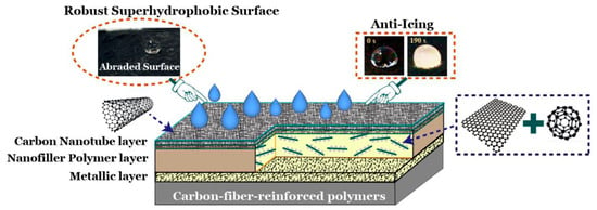
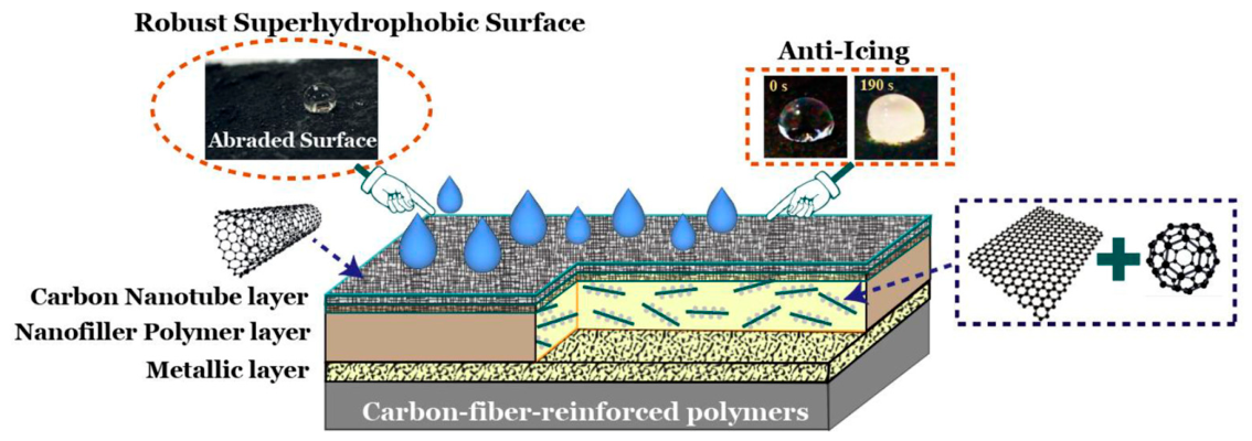
Mechanisms governing defect sealing, interfacial adhesion, and surface functionalization on metallized CFRP thus remain insufficiently understood, leaving a gap in understanding the interdependencies between defect-sealing nanocomposite modification and surface functionalization, and it remains unresolved how a hybrid GNP-C60 (2D/1D) nanocomposite sealant interacts with the inherent pore networks of HVOF-sprayed metallic coatings while providing a compatible foundation for CNT-based surface treatment. The present study advances beyond prior work by evaluating a hybrid nanocomposite defect-sealing strategy tailored to thermally sprayed metallized CFRP, combined with a functional surface treatment, in which GNP and C60 were selected as a filler pair because their contrasting morphologies provide complementary reinforcement mechanisms: the high-aspect-ratio, platelet-like geometry of GNP promotes crack deflection and creates tortuous diffusion pathways, while the spherical geometry of C60 may reduce GNP restacking and agglomeration by occupying interstitial spaces, acting as stress-redistribution sites. This combination was selected over alternative hybrid systems because the small, spherical dimensions of C60 are expected to more effectively fill interstitial gaps between GNP platelets than fibrous or larger-particulate fillers. To address these challenges, illustrated in Figure 1, this study investigates a hybrid GNP-C60 reinforced epoxy coating as a defect-sealing modification for HVOF-metallized CFRP, intended to reduce accessible surface-connected defects and improve coating integrity. A CNT-based surface treatment was introduced as a proof-of-concept approach to modify surface wettability and evaluate potential anti-icing functionality. The objectives of this study are to: (1) characterize the microstructural evolution associated with nanocomposite coating application; (2) evaluate the effects of hybrid nanofillers on adhesion, tensile behavior, abrasion resistance, and electrochemical barrier-related performance; (3) assess wettability modification and laboratory-scale anti-icing behavior resulting from CNT surface treatment; and (4) investigate relationships between coating microstructure and multifunctional coating performance.
Figure 1.
Schematic illustration of the coating modification strategy applied to HVOF-metallized CFRP, including hybrid GNP-C60 nanocomposite sealing and CNT-based surface functionalization.
The primary contribution of this work lies in the combined evaluation of defect-sealing nanocomposite modification and CNT-based surface functionalization on HVOF-metallized CFRP coatings. While previous studies have primarily focused on either mechanical/barrier enhancement or surface wettability modification independently, this work provides a unified experimental assessment of how these approaches influence coating microstructure, interfacial behavior, barrier-related properties, and surface functionality, contributing to the understanding of multifunctional coating modification strategies for metallized composite substrates.
2. Materials and Methods
2.1. Materials
Commercial CFRP plates were used as substrates in this study. The CFRP laminates were fabricated from unidirectional carbon fiber prepregs with an epoxy matrix and cured according to the manufacturer’s specifications. The average thickness of the CFRP substrates was about 0.25 mm.
The metallic layer consisted of pure aluminum alloy (99.5% purity). Fullerene (C60) nano powder (average particle size ~20 nm) was obtained from Sigma-Aldrich (St. Louis, MO, USA). GNPs with an average thickness of 8–12 nm and specific surface area of 500–700 m2/g, and multi-walled CNTs with an outer diameter of 8–15 nm and length of 10–50 μm were supplied by Cheap Tubes Inc. (Grafton, VT, USA). The epoxy matrix was EPONTM Resin 828 (bisphenol-A based epoxy resin) and was cured using EPIKURETM 3175 polyamide curing agent (both purchased from Hexion Inc., Columbus, OH, USA) with a resin-to-hardener molar ratio of 1:1.
2.2. Metallization of CFRP Substrate
Aluminum coatings were deposited onto CFRP substrates using a HIPOJET 2700M HVOF thermal spray system (Plasma Powders & Systems Inc., West Easton, PA, USA) at the Hard Coating Research Laboratory (HCRL), North Dakota State University, selected in this exploratory study for its relatively high particle impact velocity while limiting excessive thermal exposure to polymer-based substrates. Before metallization, CFRP substrates were sequentially cleaned with acetone and ethanol, dried under ambient laboratory conditions, and mounted on a fixture permitting controlled traverse motion during spraying, with surface temperature monitored and maintained below 110 °C to minimize potential thermal degradation of the CFRP matrix.
Commercial aluminum powder was used as feedstock. The HVOF spraying parameters employed in this study are described as follows: Natural gas was used as fuel with a flow rate of 236 SLPM and a fuel pressure of 10 bar. Oxygen was supplied at a pressure of 10.3 bars and a flow rate of 330 SLPM to sustain combustion. Nitrogen served as the carrier gas at a pressure of 8.6 bar. Additional compressed air was supplied at 5.1 bar for system stabilization. The spray distance (stand-off distance) was maintained at 200 mm. The nominal powder feed rate was 60.5 g/min. The resulting aluminum coating thickness was controlled at approximately 100.6 ± 2.5 μm (n = 5) and measured using cross-sectional optical microscopy. The surface roughness of the metallized coatings was measured using a KLA-Tencor P-15 surface profiler (KLA Corporation, Milpitas, CA, USA). The stylus-based profiler was used to evaluate surface roughness with high-resolution capability (up to 0.5 Å resolution). The average roughness (Ra) values were calculated from measurements at three different locations on each coating surface to ensure reproducibility. During HVOF deposition [6,7], aluminum particles were heated and accelerated at high velocity, and upon impact, underwent rapid deformation and solidification, resulting in a lamellar coating structure containing inter-splat boundaries and porosity, further characterized using SEM and micro-computed tomography.
2.3. Preparation of Hybrid Nanofiller-Reinforced Epoxy
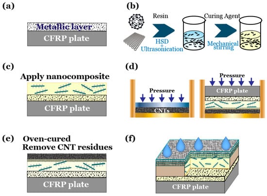
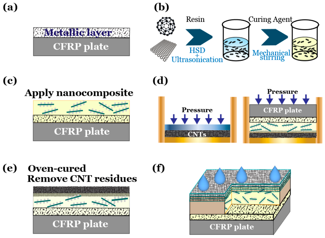
As illustrated in Figure 2b, to evaluate the influence of hybrid nanofillers on coating behavior, GNP and C60 hybrid systems were incorporated into the epoxy matrix at a total filler loading of 1 wt.%. Three GNP: C60 mass ratios were investigated: 25:75, 50:50, and 75:25.
Figure 2.
Schematic illustration of coating preparation procedures: (a) HVOF metallization of the CFRP substrate with an aluminum metallic layer; (b) preparation of the GNP-C60 hybrid nanocomposite epoxy through nanofiller dispersion, resin mixing, curing agent addition, and mechanical stirring; (c) application of the hybrid nanocomposite coating onto the metallized CFRP substrate; (d) CNT-based surface treatment through pressure-assisted CNT deposition onto the coating surface; (e) oven curing and removal of residual CNT particles; and (f) final CNT-functionalized hybrid nanocomposite coating with water-repellent surface characteristics.
Nanofillers were first dispersed into EPON 828 resin using a high-speed mechanical disperser at 4000 rpm for 30 min. To prevent thermal degradation during mixing, the dispersion vessel was immersed in an ice-water bath. Subsequently, probe ultrasonication (750 W, 20 kHz) was performed for 60 min using a 30 s on /30 s off cycle to enhance exfoliation and minimize agglomeration. After dispersion, the curing agent was added and mechanically stirred for 5 min. The mixture was degassed under vacuum for 10 min before coating application.
2.4. Fabrication of Duplex Coating
The hybrid nanofiller-reinforced epoxy was applied onto metallized CFRP substrates via dip coating using a motorized dip-coater (Ossila Dip Coater, L2006A1, Ossila Ltd., Sheffield, UK) at a controlled immersion and withdrawal rate of 0.2 mm/s (Figure 2c), producing an average coating thickness of 110 ± 5 μm (n = 5), measured by a film thickness gauge. After air drying for 2 h at room temperature to increase viscosity, a concentrated CNT layer was introduced by pressing the semi-cured surface against a pre-compacted CNT bed under a pressure of 2.0 kPa for 30 s (Figure 2d). Excess CNTs were removed by gentle air blowing. Final curing was conducted at 60 °C for 15 min in a convection oven (Figure 2e), followed by post-curing at room temperature for 48 h. The coating preparation procedure was designed to evaluate the influence of hybrid nanocomposite modification on metallized CFRP coatings and to explore the feasibility of introducing additional surface functionality through CNT surface treatment.
2.5. Characterization Methods and Evaluations
Surface morphologies were examined using a field-emission scanning electron microscope (FE-SEM, JSM-7600F, JEOL, Tokyo, Japan). Fracture surfaces and abraded regions were analyzed to evaluate filler dispersion, crack propagation characteristics, and wear mechanisms. Microstructural porosity of the HVOF aluminum coating before and after nanocomposite infiltration was characterized using micro-computed tomography (micro-CT, GE v|tome|x S system, v2.0, GE Sensing & Inspection Technologies, Wunstorf, Germany) at an isotropic voxel size of 43.909 μm, representing the nominal spatial resolution of the reconstructed images; based on established micro-CT imaging practices, the practical detection limit is approximately 2–3 times the voxel size (≈88–132 μm), so pores or defects smaller than this range may not be reliably resolved under the applied scanning conditions. Reconstructed datasets were analyzed using embedded color-based image segmentation method software to quantify open porosity and pore size distribution within a scanned volume of approximately 15 × 20 mm and a thickness of ~1 mm.
The particle size distribution of nanofillers was determined by dynamic light scattering (DLS) using a Nicomp 380 submicron particle sizer, with samples dispersed in ethanol before measurement. Nanofiller morphology was examined using transmission electron microscopy (TEM, JEM-2100, JEOL, Japan) after ultrasonic dispersion in ethanol and deposition onto copper grids.
Surface roughness and topography were characterized using an Oxford Jupiter XR atomic force microscope (AFM, Oxford Instruments Asylum Research, Santa Barbara, CA, USA) equipped with a 100 μm extended-range scanner, employed to examine both pristine and mechanically abraded regions of nano-coated specimens. The Jupiter XR AFM combines high-speed imaging with an extended scanning range, offering imaging speeds of 10, 20, and 40 Hz, and was operated in tapping mode at an imaging speed of 10, 20, and 40 Hz using a HQ: CSC37/Al BS silicon probe (MikroMasch, Wetzlar, Germany) with a resonance frequency of 30–55 kHz and a spring constant of 0.3–2.0 N/m. Measurements were performed over a scan area of 20 × 20 μm, at three different locations per sample. Both 2D and 3D topographical images were obtained, providing high-resolution, three-dimensional surface mapping to quantitatively assess morphological features and roughness parameters (Ra) across different specimen conditions. Average roughness (Ra) was calculated using the instrument’s built-in Ergo image analysis software: following image acquisition, a region of interest was defined within the scanned area, and the corresponding Ra value was generated directly within the software’s statistics panel. Rheological behavior of neat epoxy and nanocomposite systems was measured using a Brookfield DV-II viscometer (Brookfield Engineering Laboratories, Middleboro, MA, USA) at 23 °C using spindle #7 at 50 rpm. Measurements were considered valid when torque values were between 10% and 90%. At least three measurements were performed for each sample, and the reported values represent the average.
Tensile properties of free-standing cured nanocomposite films were measured in accordance with ASTM D638 [41] using a universal testing machine at a crosshead speed of 5.0 mm/min, with at least five specimens tested per formulation. Abrasion resistance was evaluated using a Taber Abraser (Taber Industries, North Tonawanda, NY, USA) in accordance with ASTM D4060 [42] equipped with CS-10 wheels under a load of 250 g at 72 rpm, with mass loss recorded after 1000 and 2000 cycles and wear tracks subsequently examined by SEM. Pull-off adhesion strength was measured following ASTM D4541 [43] using a hydraulic adhesion tester, with three replicates performed for each coating condition. Electrochemical impedance spectroscopy (EIS) was performed using a Gamry Reference 600 potentiostat (Gamry Instruments, Warminster, PA, USA) in a three-electrode configuration to assess the barrier-related performance of the hybrid nanocomposite coating deposited on the metallized aluminum surface. The CNT functional top layer was not included in the electrochemical evaluation. A saturated calomel electrode (SCE) served as the reference electrode, a platinum mesh as the counter electrode, and the coated sample as the working electrode. A 3 cm diameter O-ring cell defined the exposed area. Impedance spectra were collected over a frequency range of 10 mHz to 100 kHz and analyzed using Bode plots.
Static water contact angles were measured using a goniometer with 5 μL deionized water droplets, and reported values represent the average of five measurements at different surface locations. Icing delay performance was assessed in an environmental chamber maintained at −10 ± 1 °C. Samples were equilibrated for 20 min prior to testing. A 10 μL water droplet (~0 °C) was deposited onto the surface, and freezing time was recorded using high-speed imaging. A dynamic ice-water dripping test was also conducted at −10 °C with samples positioned at a 15° tilt angle and water delivered at 2 mL/min from a height of 10 cm. The experimental program provided an initial feasibility assessment of the proposed multilayer coating concept, focusing on relationships between microstructural modification, interfacial behavior, and surface functionality; extended durability and large-scale validation remain for future investigation.
3. Results and Discussion
3.1. Initial Defect State of the HVOF-Sprayed Aluminum Coating and Microstructural Analysis
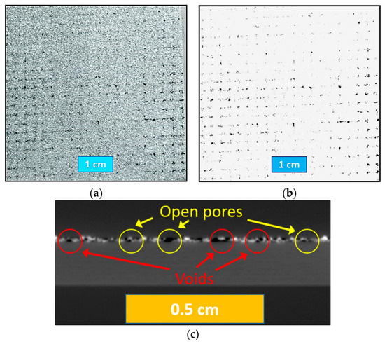
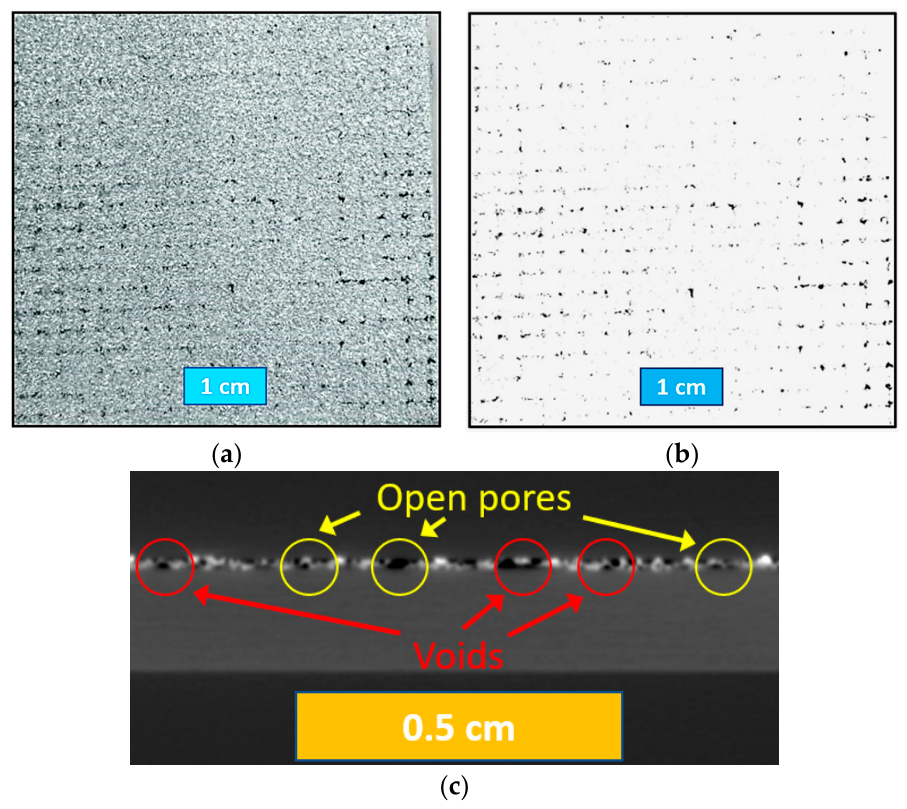
The as-deposited HVOF aluminum coating on CFRP substrates exhibited characteristic structural heterogeneities associated with thermal spray deposition onto polymeric materials [2,3,4,5,6,7,8,9,10,11,12]. Surface optical imaging (Figure 3a) revealed discontinuous metallic coverage with localized dark regions corresponding to exposed CFRP substrate. Pixel-based image analysis (Figure 3b) was performed to quantify these surface defects using:
Figure 3.
Surface defect analysis of as-sprayed metallized CFRP: (a) optical image of surface morphology, (b) pixel-based color segmentation for defect quantification, and (c) micro-CT cross-sectional reconstruction.
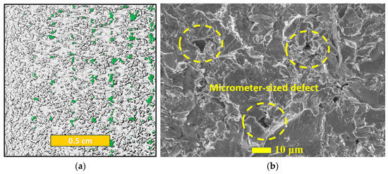
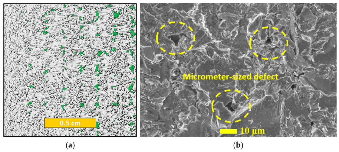
The calculated defect ratio was approximately 2% of the total surface area, with defect spots ranging from 0.02 to 0.10 cm in diameter, with the largest defects reaching approximately 0.13 cm. Three-dimensional micro-CT reconstruction (Figure 3c) further indicated distributed internal porosity within the aluminum layer, consistent with lamellar voids and discontinuities characteristic of HVOF coatings. SEM examination (Figure 4) confirmed the presence of microcracks (~20 μm) and pores (~10 μm), with pore sizes primarily distributed between 10 and 100 μm. These defects are commonly attributed to incomplete particle deformation and limited interparticle bonding during thermal spray deposition [2,8,9,10,11,26], compounded on CFRP substrates by lower surface hardness and limited plastic accommodation capability relative to metallic substrates, which favor incomplete particle flattening, elastic rebound, and inter-splat gap formation.
Figure 4.
Microstructural characterization of the as-sprayed HVOF aluminum coating on CFRP: (a) micro-CT surface visualization and (b) SEM surface morphology showing microcracks and pores.
These defects are commonly attributed to incomplete particle deformation and limited interparticle bonding during thermal spray deposition [2,8,9,10,11,26]. Compared with metallic substrates that facilitate extensive plastic deformation and interlocking, CFRP substrates possess lower surface hardness and limited plastic accommodation capability. Consequently, incomplete particle flattening and elastic rebound effects may contribute to insufficient consolidation and formation of inter-splat gaps, providing pathways for moisture ingress and localized stress concentration during mechanical loading.
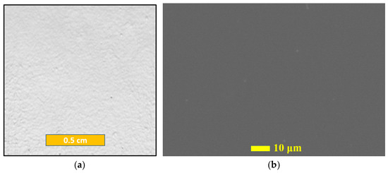
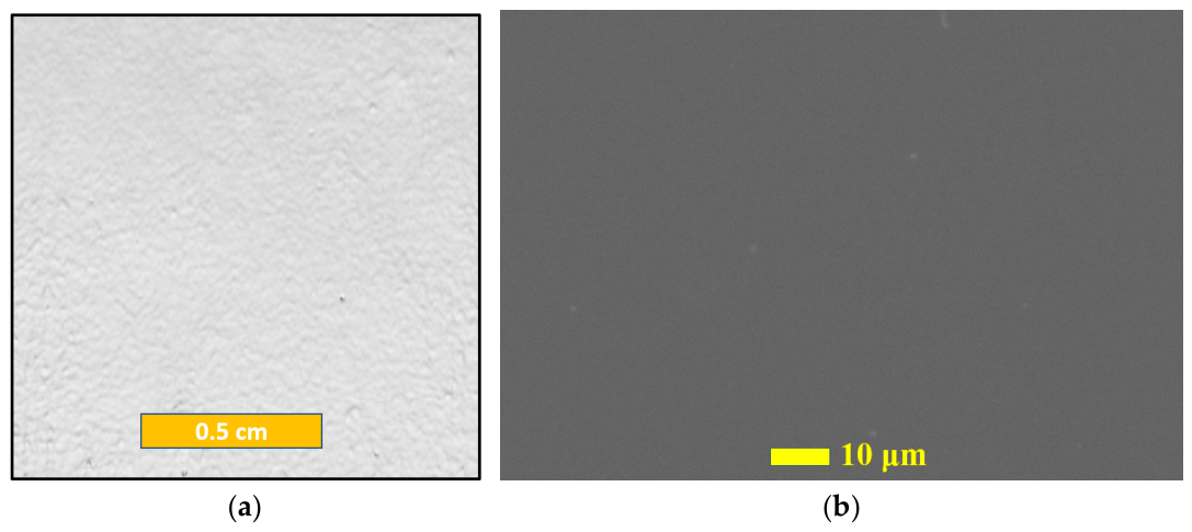
Following application of the hybrid GNP-C60 reinforced epoxy, SEM images (Figure 5) indicated relatively uniform surface coverage without visible large-scale cracks or exposed substrate regions, while micro-CT reconstruction suggested a substantial reduction in accessible interconnected porosity. Considering the spatial resolution limitation of the micro-CT system (voxel size: 43.909 μm; practical detection limit: approximately 88–132 μm), residual open porosity within the scanned volume was reduced below the measurable threshold after nanocomposite infiltration, indicating that the hybrid interlayer effectively sealed accessible surface-connected defects and larger interconnected pores generated during the as-sprayed condition. SEM and micro-CT observations were consistent with occupation and coverage of accessible surface-connected defects by the nanocomposite coating, although these techniques provide morphological rather than direct quantitative evidence of defect filling.
Figure 5.
Microstructural evolution after hybrid nanocomposite infiltration: (a) micro-CT image and (b) SEM surface morphology of duplex-coated metallized CFRP.
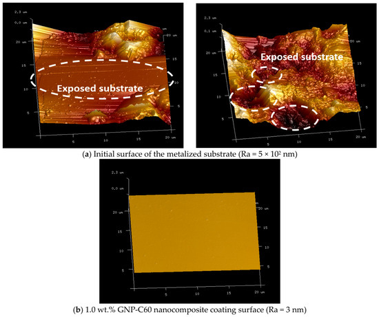
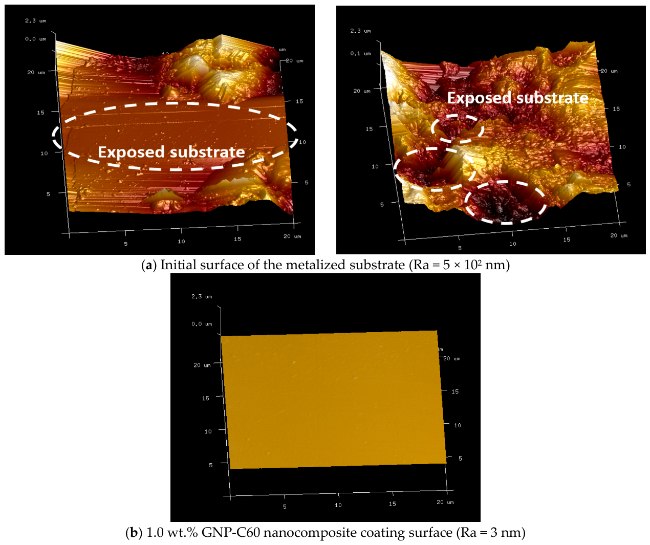
AFM analysis (20 × 20 μm scan area) corroborated this trend at the nanoscale: the as-metallized surface exhibited an average roughness (Ra) on the order of 5 × 10² nm (Figure 6a), consistent with the lamellar HVOF morphology, whereas the 1.0 wt.% GNP-C60 nanocomposite interlayer reduced roughness to approximately 3 nm (Figure 6b), similar to reductions reported in other polymer nanocomposite systems with improved matrix-filler interaction [27,28,29,30,31,32,33,34,35].
Figure 6.
AFM surface topography (20 × 20 μm scan area) of (a) as-sprayed metallized CFRP substrate (Ra = 5 × 10² nm) and (b) hybrid nanocomposite-modified coating surface (Ra = 3 nm).
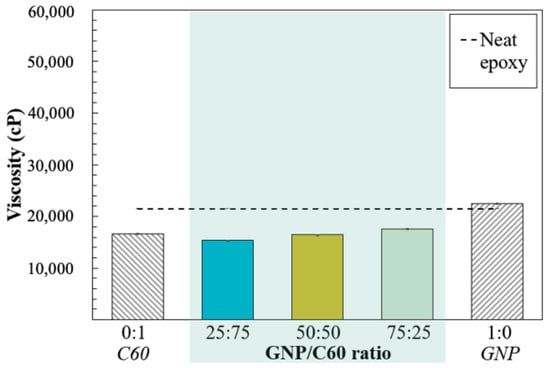
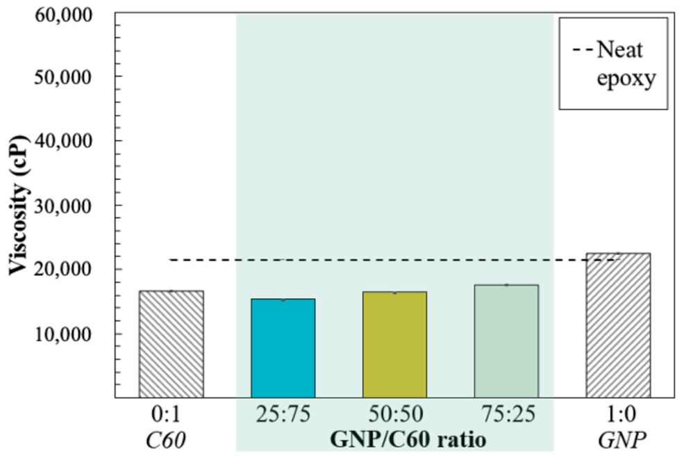
Viscosity measurements (Figure 7) relate directly to this defect-filling behavior: incorporation of 1.0 wt.% hybrid GNP-C60 nanofillers reduced epoxy viscosity from approximately 21,440 cP to 16,000 cP at 23 °C, consistent with reports attributing viscosity reduction at low nanofiller loading to improved particle dispersion and lubricating effects [31,32]. Lower viscosity is associated with improved wetting and accessibility to porous surface features during coating application [27,28,29,30,31,32,33,34]; although penetration depth was not directly quantified, this rheological trend is consistent with the micro-CT and AFM evidence of reduced accessible porosity, together indicating that the hybrid nanocomposite coating combined suitable flow characteristics with effective occupation of the ~2% porosity present in the as-sprayed HVOF aluminum coating.
Figure 7.
Viscosity of epoxy systems reinforced with GNP, C60, and hybrid GNP-C60 nanofillers.
To sum up, the microstructural characterization results demonstrate that the hybrid GNP-C60 nanocomposite coating altered the surface morphology and defect characteristics of the metallized CFRP coating while maintaining suitable rheological behavior for coating application. Although the present study does not directly quantify defect-filling depth or interfacial penetration, the observed reduction in accessible porosity is consistent with the improved adhesion, abrasion resistance, and barrier-related performance discussed in the following sections.
3.2. Mechanical Reinforcement: Tensile Behavior and Fracture Morphology of Hybrid Nanocomposite Coatings
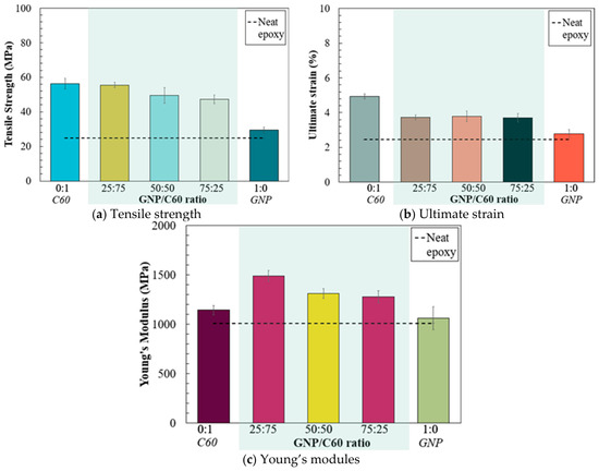
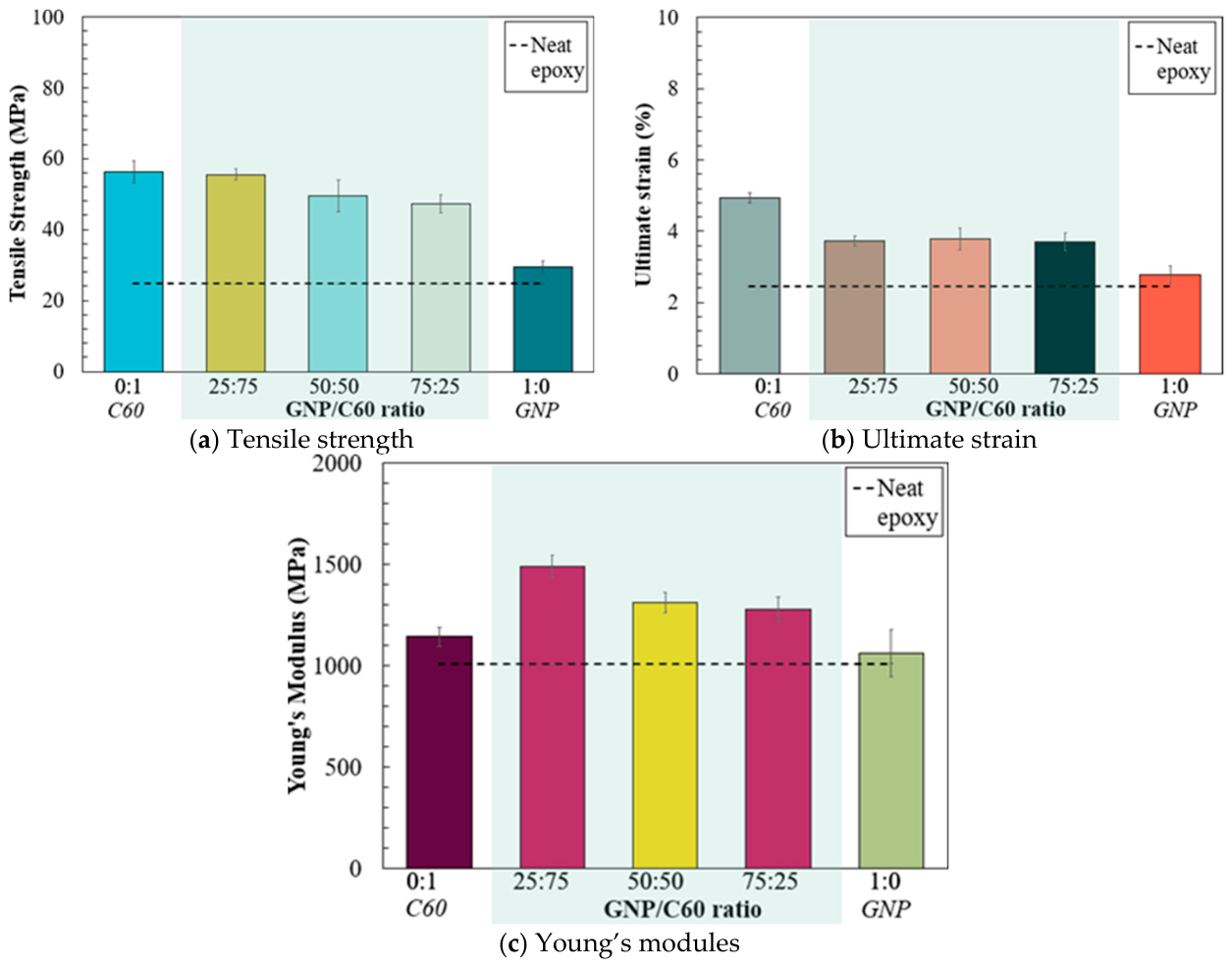
The mechanical, tribological, interfacial, and barrier-related properties of the hybrid GNP-C60 nanocomposite coating were evaluated to assess the influence of nanofiller incorporation on coating performance. The experimental program was designed to provide a feasibility assessment of the potential benefits of hybrid nanocomposite modification for HVOF-metallized CFRP coatings. The tensile properties of the hybrid GNP-C60 reinforced epoxy interlayer were evaluated to quantify nanofiller-induced reinforcement and to assess the potential mechanical compatibility of the duplex coating architecture with the underlying HVOF-sprayed aluminum/CFRP system. The tensile strength, ultimate strain, and Young’s modulus of the investigated formulations are summarized in Figure 8. As shown in Figure 8a, all nanofiller-reinforced composites exhibited improved tensile strength compared with neat epoxy. Among the hybrid systems, the GNP: C60 ratio of 25:75 achieved the highest tensile strength of 56 MPa, corresponding to an increase of approximately 124% relative to neat epoxy. Notably, this strength level was comparable to that of the C60-only reinforced system, suggesting that partial substitution of C60 with GNP maintained similar reinforcement efficiency at the investigated loading level. A gradual reduction in tensile strength was observed with increasing GNP content within the hybrid system. The GNP: C60 ratio of 75:25 exhibited a tensile strength of 47 MPa, which, although lower than the other hybrid formulations, still exceeded the performance of neat epoxy and GNP-only reinforced systems.
Figure 8.
Tensile properties of hybrid nanocomposite systems (a–c).
The ultimate strain behavior (Figure 8b) exhibited a different trend. While the C60-only composite displayed the highest elongation at failure, the hybrid systems showed slightly reduced ultimate strain values (~3.7%), indicating that incorporation of GNP may reduce matrix flexibility. This behavior is proposed to be associated with the rigid platelet-like geometry and high aspect ratio of GNP, which may restrict polymer chain mobility through strong interfacial interactions and physical confinement, thereby reducing matrix flexibility and limiting plastic deformation [36,37]. Nevertheless, the hybrid formulations maintained higher failure strain than neat epoxy and GNP-only reinforced systems, indicating a relatively balanced combination of reinforcement and ductility. Young’s modulus (Figure 8c) showed the inverse compositional trend to strain: the 75:25 ratio produced the highest modulus increase (~47% relative to neat epoxy), consistent with the comparatively lower stiffness contribution of GNP relative to C60 also seen in the strength data.
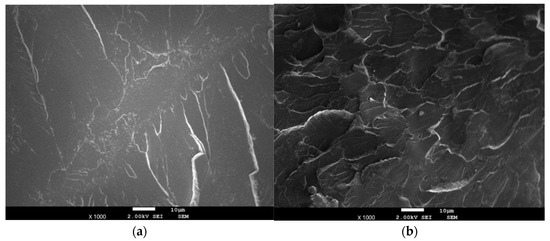
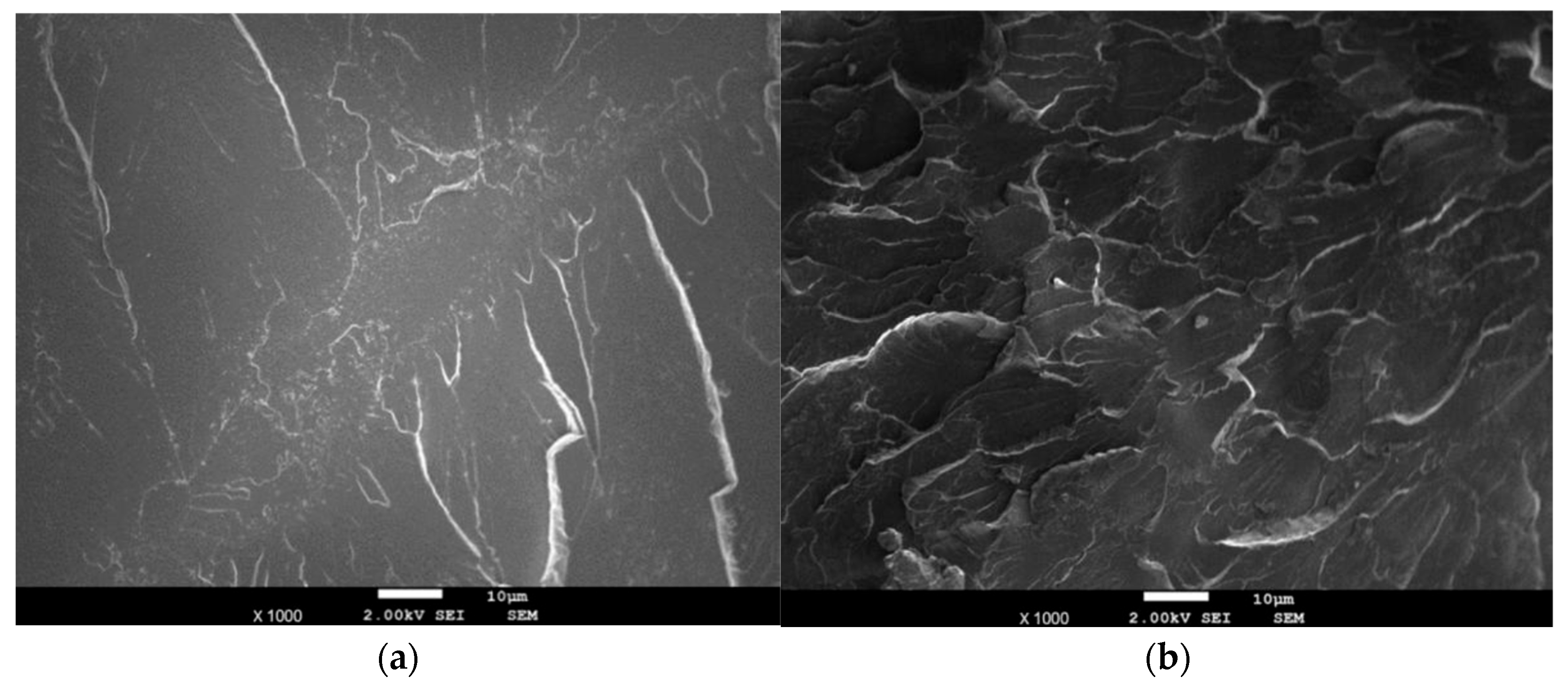
The hybrid nanofillers effectively reinforced the epoxy matrix, with increased tensile strength and modulus indicating improved load-bearing capability while retained moderate failure strain confirmed excessive embrittlement did not occur. This enhanced performance is consistent with platelet-shaped GNP and spherical C60 contributing stress redistribution and crack-growth resistance through different reinforcing mechanisms, supported by the rougher fracture morphology observed in Figure 9. As discussed in Section 3, infiltration of the nanocomposite into accessible surface-connected porosity may also promote mechanical anchoring within the metallic layer, improving mechanical continuity between the aluminum coating and CFRP substrate and partially reducing localized interfacial strain incompatibility during loading. As these tensile properties were obtained from free-standing specimens rather than the complete multilayer assembly, the present results should be used primarily as an initial indication of the reinforcing potential of the hybrid interlayer rather than a direct measurement of the integrated coating system’s structural performance. Fractographic SEM analysis of neat epoxy and hybrid nanocomposite interlayers after tensile testing (Figure 9) showed that neat epoxy exhibited a smooth, featureless fracture surface (Figure 9a) characteristic of brittle failure with limited plastic deformation, crack deflection, or energy dissipation capability. In contrast, the hybrid GNP-C60 nanocomposite displayed a noticeably rougher fracture morphology (Figure 9b), with crack branching, tortuous fracture paths, localized deformation regions, and cleavage step formation, suggesting enhanced energy absorption during crack propagation. This toughening behavior may be associated with multiple reinforcing mechanisms operating at different length scales: GNP’s high aspect ratio and planar morphology may divert propagating cracks along the filler-matrix interface, increasing fracture path length and energy consumption, while C60 nanoparticles may act as localized stress redistribution sites that interrupt crack continuity and reduce local stress concentration. This interpretation is consistent with the tensile results, where the 25:75 GNP: C60 formulation exhibited relatively balanced enhancement in strength and stiffness.
Figure 9.
Fracture surface morphology after tensile failure: (a) neat epoxy and (b) 1 wt.% GNP-C60 (25:75) hybrid nanocomposite.
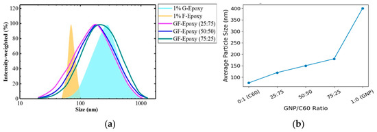
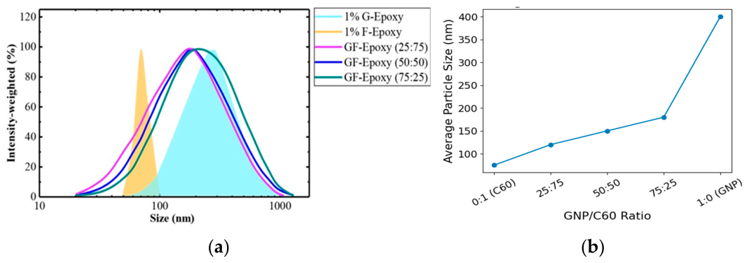
To provide additional insight into the nanofiller characteristics before coating preparation, particle size distributions of GNP, fullerene-C60, and the hybrid GNP-C60 system were evaluated using dynamic light scattering (DLS). The particle size distributions of GNP, fullerene-C60, and the hybrid GNP-C60 system are presented in Figure 10.
Figure 10.
Particle size characterization of nanofillers: (a) particle size distribution curves and (b) average particle size as a function of GNP: C60 ratio.
The C60 suspension exhibited a relatively narrow particle size distribution, whereas the GNP suspension showed a broader apparent size distribution, which is consistent with the platelet-like morphology of graphene nanoplatelets. The hybrid GNP-C60 suspension exhibited a narrower apparent particle size distribution and a reduced average particle size compared with the GNP-only suspension. These results suggest that interactions between GNP and C60 may reduce the formation of large agglomerates during suspension preparation. It should be noted that the DLS measurements characterize the nanofiller suspension before coating preparation and are therefore used herein as a qualitative indicator of particle size distribution rather than a direct measurement of nanofiller dispersion within the cured epoxy matrix.
3.3. Abrasion Resistance
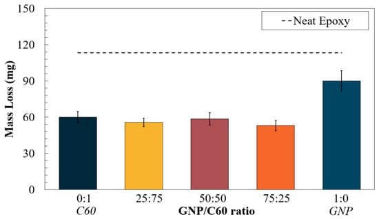
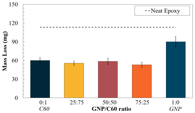
Abrasion resistance (Figure 11), evaluated by Taber testing (ASTM D4060), followed the same compositional pattern as the tensile and fracture results. Neat epoxy lost 114 mg after 1000 cycles; C60-only epoxy lost approximately 60 mg, and GNP-only epoxy approximately 90 mg. Incorporation of nanofillers reduced material loss considerably. The hybrid GNP-C60 systems exhibited the lowest mass loss values, with the 1 wt.% GF-Epoxy (25:75) and GF-Epoxy (75:25) formulations showing approximately 54 mg loss after 1000 cycles. This corresponds to a reduction of more than 50% relative to neat epoxy.
Figure 11.
Abrasion resistance of nanocomposite systems measured by mass loss under Taber abrasion testing.
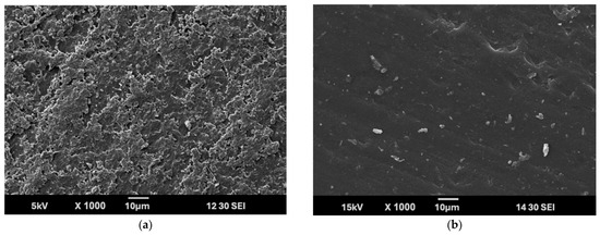
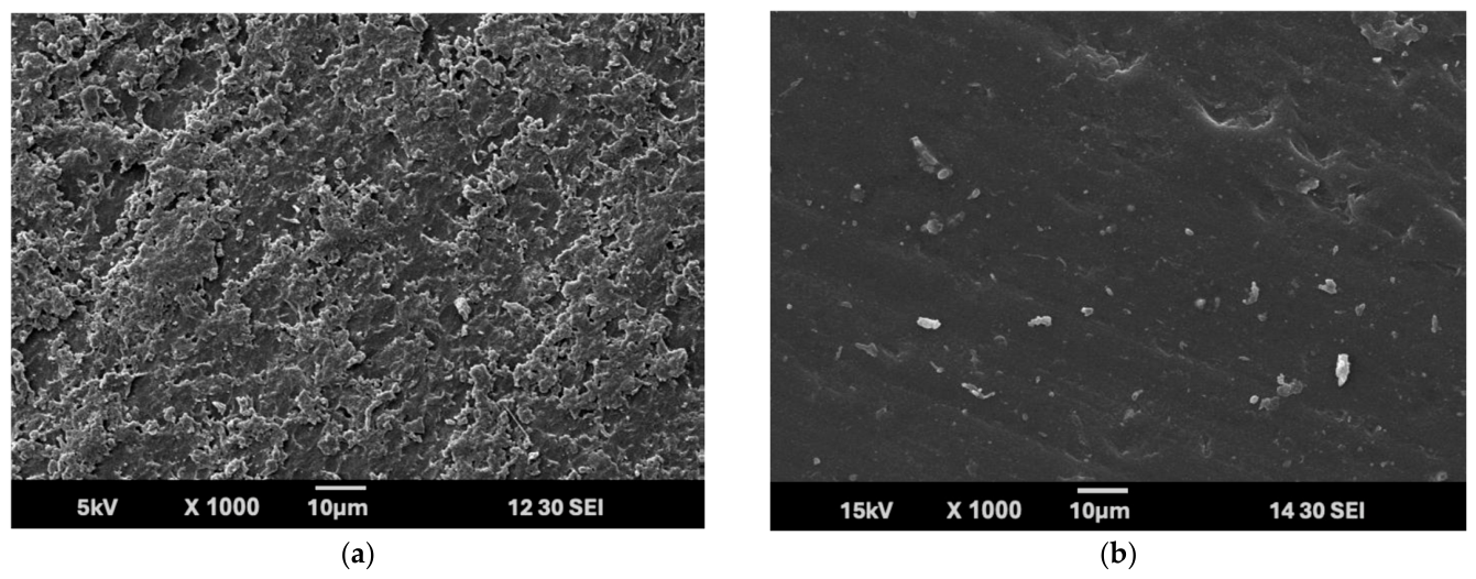
The improved abrasion resistance of the hybrid systems suggests the formation of a reinforced nanostructured network capable of resisting micro-cutting and localized deformation during repeated abrasive contact, with C60 nanoparticles contributing resistance against localized micro-fracture and GNP platelets assisting load transfer and suppression of crack propagation along the wear track. The neat epoxy surface (Figure 12a) exhibited extensive micro-cleavage features, deep grooves, and brittle fracture regions, indicating severe material removal. In contrast, the hybrid nanocomposite surface (Figure 12b) displayed shallower grooves and fewer fracture features, suggesting improved structural integrity during abrasion exposure. Reduced material loss and less severe surface damage may therefore contribute to preservation of coating integrity and reduction of defect exposure during service.
Figure 12.
SEM images of abraded surfaces: (a) neat epoxy and (b) 1 wt.% GNP-C60 (25:75) hybrid nanocomposite.
3.4. Adhesion Improvement
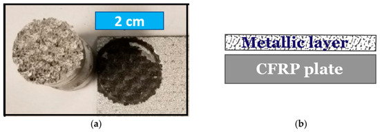
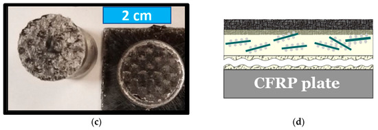
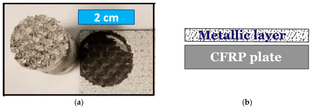
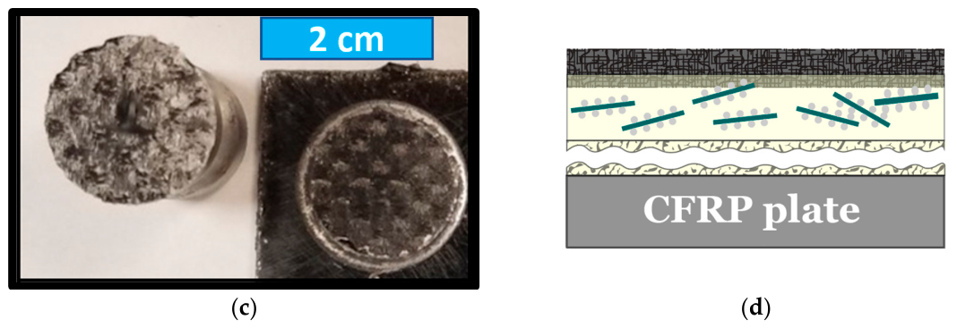
Pull-off adhesion testing (ASTM D4541) linked the microstructural defect-sealing described in Section 3.1 to interfacial performance. The as-sprayed HVOF aluminum coating exhibited a pull-off strength of approximately 46.4 kPa (320 psi), with failure occurring predominantly at the metal-CFRP interface (Figure 13a), indicating limited interfacial bonding. Following the hybrid GNP-C60 nanocomposite interlayer, the measured adhesion strength increased to approximately 94.3 kPa (650 psi), corresponding to an improvement of more than 100% relative to the as-sprayed condition. In addition, the dominant failure mode shifted from adhesive failure at the metal-CFRP interface toward cohesive failure within the interlayer itself (Figure 13b). This change in failure behavior suggests improved interfacial continuity and stronger mechanical interaction between layers. The adhesion improvement may be associated with several factors: Micro-CT observations (Section 3.1) suggested that the nanocomposite coating occupied and covered accessible surface-connected defects within the HVOF aluminum layer, increasing effective contact area and decreasing localized stress concentration sites that could otherwise facilitate interfacial failure. The enhanced cohesive strength of the nanocomposite coating itself, as evidenced by the tensile results, may also contribute to the observed transition from adhesive to cohesive failure. From a multilayer system perspective, improved adhesion may help reduce susceptibility to delamination and interfacial crack propagation during loading or environmental exposure, these laboratory-scale measurements do not represent a comprehensive long-term durability evaluation under realistic service environments. Overall, the pull-off results suggest that hybrid nanocomposite modification improved the adhesion behavior of the metallized coating system. The observed transition from adhesive failure to cohesive failure is consistent with enhanced coating continuity and improved interfacial interaction following nanocomposite application.
Figure 13.
Pull-off adhesion test results: (a,b) failure morphology of as-sprayed metallized CFRP and (c,d) hybrid nanocomposite-modified system.
3.5. Electrochemical Barrier Performance of Hybrid Nanocomposite-Sealed Aluminum Layer
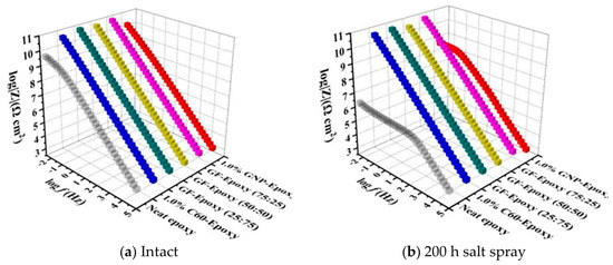
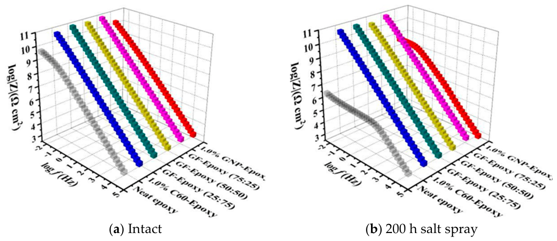
The electrochemical barrier performance of the hybrid GNP-C60 nanocomposite interlayer was evaluated using EIS to examine whether the defect sealing and interfacial densification observed in Section 3 correspond to improved resistance against electrolyte penetration; the CNT top functional layer was not included in the EIS measurements. Figure 14 presents the Bode impedance and phase angle plots for neat epoxy, single-filler systems, and hybrid GNP-C60 nanocomposite coatings before salt spray exposure. Compared with neat epoxy, all nanofiller-reinforced systems exhibited increased low-frequency impedance (|Z|0.01 Hz), hybrid GNP-C60 formulations values on the order of 1010 Ω·cm2, approximately three orders of magnitude higher than neat epoxy (~106 Ω·cm2), while phase angle values remained close to 90° over a broad frequency range, consistent with capacitive behavior of continuous protective layers.
Figure 14.
EIS Response of hybrid nanocomposite-sealed aluminum layer: (a) Bode magnitude plots before exposure and (b) after salt spray exposure.
The improved impedance response is consistent with the microstructural observations of reduced accessible porosity, which may hinder electrolyte transport and increase resistance to ionic penetration through the coating. After 200 h of salt spray exposure (Figure 14b), hybrid nanocomposite-coated systems maintained stable impedance and phase angle profiles, while neat epoxy and certain single-filler systems showed noticeable reductions in low-frequency impedance, indicating progressive electrolyte ingress. Although minor variations existed among hybrid filler ratios, no substantial differences in barrier-related behavior were detected between hybrid and fullerene-only systems after exposure, suggesting the primary improvement mechanism is associated more strongly with defect sealing and interfacial densification than filler ratio. Overall, the hybrid nanocomposite interlayer may improve electrochemical barrier behavior through reduction of accessible pore connectivity and improved interfacial continuity, though these corrosion-related observations apply specifically to the hybrid interlayer rather than the complete multilayer surface system, and represent a preliminary laboratory-scale assessment.
4. Preliminary Surface Functionalization via CNT Treatment
The surface functional behavior of the proposed multilayer system was evaluated to preliminarily assess the influence of the CNT-based surface treatment on wettability transition, anti-icing response, and retention of water-repellent behavior under mechanical exposure. The experiments presented in this section were intended primarily as feasibility-level evaluations of functional surface behavior rather than comprehensive long-term environmental qualification tests.
4.1. Wettability Transition and CNT-Based Surface Functionalization
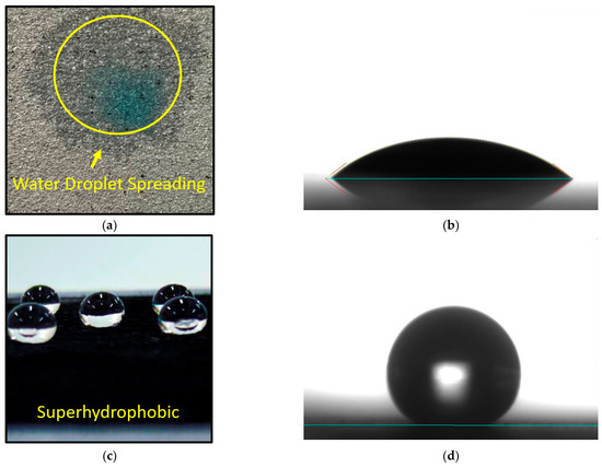
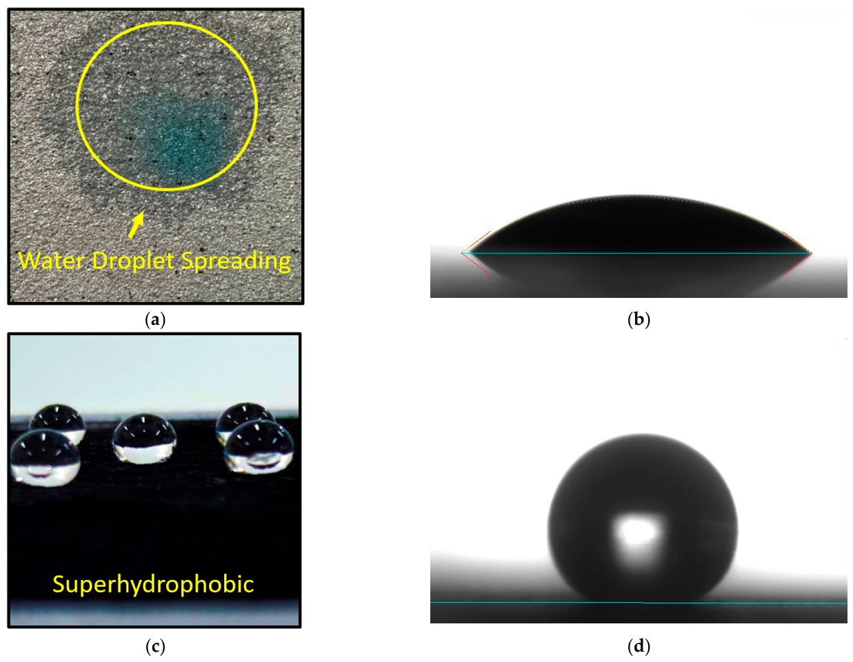
The surface wettability of the metallized CFRP system was characterized using static water contact angle measurements to evaluate the functional influence of the CNT top layer. As shown in Figure 15, the as-sprayed HVOF aluminum surface exhibited hydrophilic behavior, with water spreading readily across the surface and a measured static contact angle of approximately 23°. The surface also displayed nearly complete wetting in the presence of oil, indicating relatively high surface energy and strong liquid-solid affinity.
Figure 15.
Wettability characterization of as-sprayed and CNT-modified surfaces: optical images and static contact angle measurements. (a) Observation of the as-spray surface; (b) Water contact angle (23°) of the as-spray surface; (c) Observation of the new duplex coating surface; (d) Water contact angle (169°) of the new duplex coating surface (oil contact angle of 158°).
This hydrophilic response is consistent with the presence of surface-connected porosity and exposed metallic features associated with the HVOF coating morphology. Open splat boundaries and microcracks may facilitate water penetration into the coating and potentially increase moisture interaction with the underlying metallized structure.
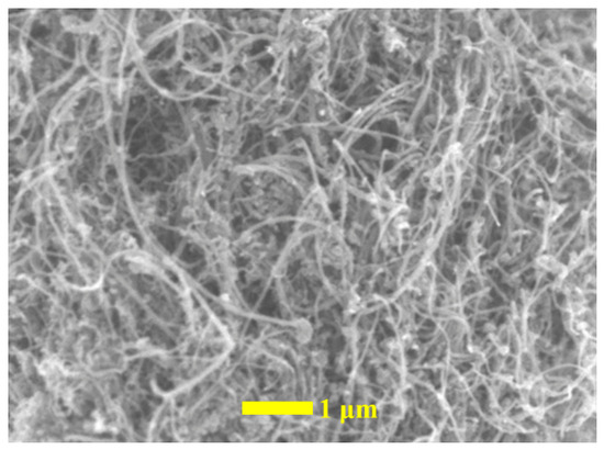
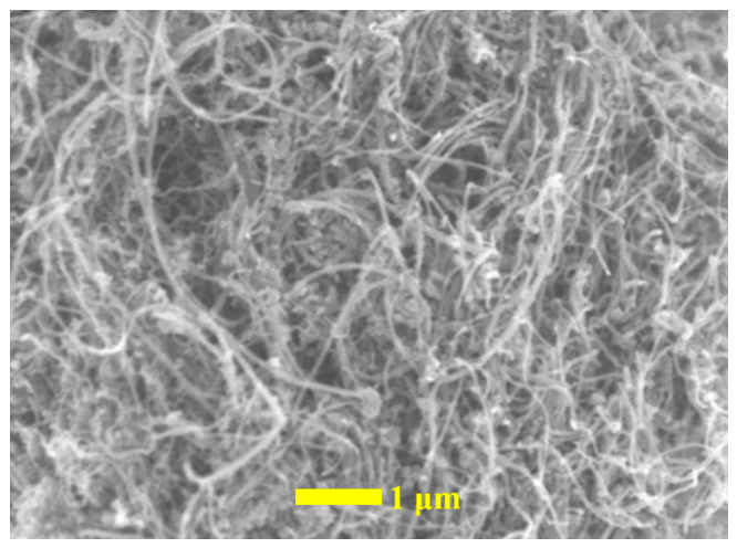
Following deposition of the CNT top layer, a pronounced wettability transition was observed. The modified surface exhibited a static water contact angle of approximately 155°, with localized measurements approaching 169° (Figure 15). Oil contact angles of approximately 158° further suggest the formation of a low-surface-energy hierarchical interface. SEM imaging (Figure 16) revealed a relatively uniform CNT network forming nanoscale roughened features superimposed on the microscale roughness inherited from the underlying hybrid nanocomposite interlayer.
Figure 16.
SEM morphology of CNT-modified surface showing hierarchical nanoscale roughness.
The observed superhydrophobic behavior may be interpreted using the classical Cassie-Baxter wetting model [27,28,29,32]. For a rough composite surface, the apparent contact angle () is expressed as:
where represents the fraction of solid surface in direct contact with the liquid and is the intrinsic contact angle of the flat material surface.
The CNT layer introduces nanoscale asperities that, together with the microscale roughness of the underlying surface, create a dual-scale topography capable of trapping air pockets beneath droplets, reducing the effective solid–liquid contact fraction, increasing the apparent contact angle, and decreasing droplet adhesion as the surface transitions from a fully wetted Wenzel-type interface toward a composite solid-air interface. The CNT layer primarily functions as a surface treatment layer rather than a load-bearing structural component, with its stability depending on the mechanically reinforced hybrid nanocomposite interlayer beneath it, which may provide mechanical support and adhesion, assisting retention of the nanoscale CNT morphology during environmental or mechanical exposure. Reduced droplet adhesion can decrease water residence time and limit prolonged contact between water and accessible surface features, while rolling droplets may facilitate the removal of dust and loose contaminants, reducing localized moisture retention. Although these effects were not quantified directly, the observed wettability transition suggests CNT surface treatment may provide a feasible approach for introducing water-repellent functionality onto metallized CFRP coatings. The wettability characterization presented here was based primarily on static contact angle measurements; dynamic wetting behavior, including sliding angle and droplet mobility characterization, was not investigated, and the transition toward a composite solid-air interface may also influence interfacial heat transfer and icing behavior under freezing conditions, preliminarily evaluated in the following section.
4.2. Preliminary Evaluation of Icing Behavior
The anti-icing behavior of the metallized CFRP system was preliminarily evaluated using two complementary experiments: (i) static icing-delay testing and (ii) dynamic water-dripping exposure under freezing conditions. Both experiments were conducted inside an environmental chamber maintained at −10 ± 1 °C to approximate freezing conditions potentially relevant to outdoor environmental exposure.
4.2.1. Icing Delay Behavior
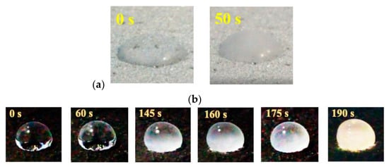
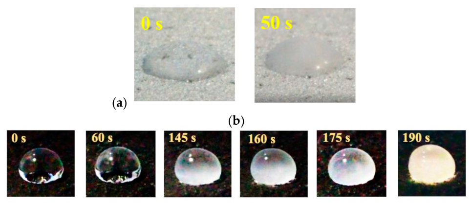
Before testing, specimens were placed inside the chamber for approximately 20 min to establish thermal equilibrium between the sample surface and the surrounding environment. A 10 μL water droplet, maintained near 0 °C by mixing with ice immediately before testing, was released from a height of 3 cm above the surface. Freezing time was recorded using high-speed video imaging, with timing initiated upon droplet-surface contact. On the as-sprayed metallized CFRP surface, complete freezing occurred within approximately 50 s (Figure 17a). Under freezing conditions, the droplet initially formed a dome-shaped geometry rather than spreading completely, likely due to rapid localized freezing near the contact interface. The relatively short freezing time may be associated with the large solid–liquid contact fraction and efficient thermal conduction through the metallic aluminum layer, which accelerates heat transfer from the droplet to the cold substrate [39]. In contrast, the CNT-modified duplex surface exhibited a substantially extended freezing time of approximately 190 s (Figure 17b), corresponding to nearly a threefold increase relative to the untreated metallized surface.
Figure 17.
Static icing-delay evaluation of (a) as-sprayed metallized CFRP and (b) CNT-modified surface.
The extended freezing time observed for the CNT-modified surface may be associated with the altered wetting state created by the hierarchical surface morphology. Under Cassie–Baxter-type wetting conditions, droplets contact only a portion of the solid surface while partially resting on trapped air pockets. This reduction in effective contact area may decrease heat transfer between the droplet and substrate. In addition, air trapped within surface asperities may provide localized thermal insulation because of its low thermal conductivity relative to the underlying solid. Together, these effects may contribute to the observed increase in freezing time. The combined reduction in contact area and interfacial thermal conduction, therefore, appears to delay ice nucleation and freezing progression. Although the present results suggest promising anti-icing behavior, the experiments were conducted under controlled laboratory conditions using static droplets. Additional studies involving ice adhesion measurements, cyclic freezing exposure, and outdoor environmental testing would be beneficial for a more comprehensive evaluation of practical anti-icing performance.
4.2.2. Dynamic Water-Dripping Test
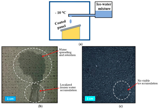
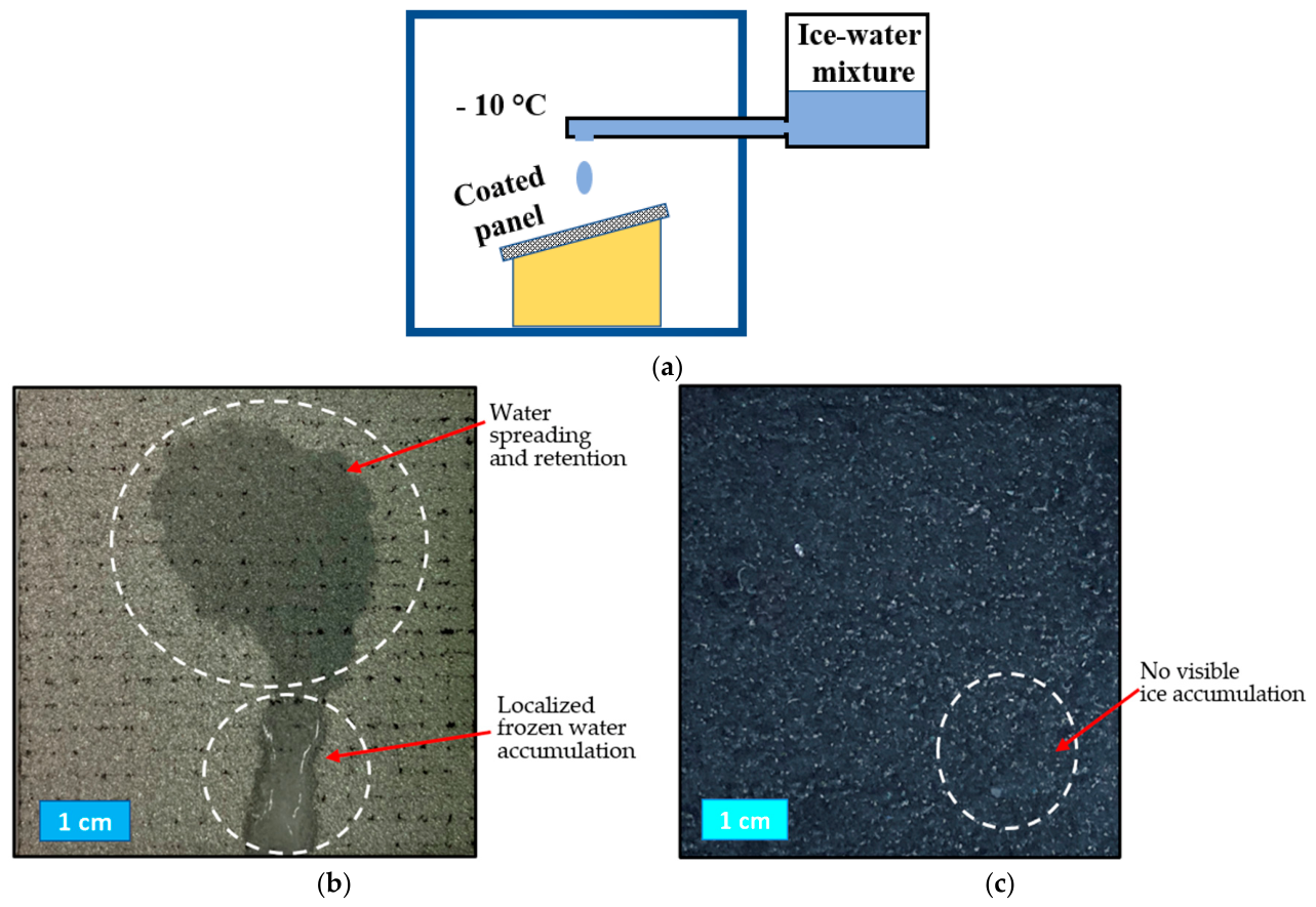
To simulate more severe icing exposure conditions, a dynamic water-dripping experiment was conducted under the same −10 ± 1 °C chamber environment (Figure 18a). Specimens were positioned at a tilt angle of 15° to approximate inclined structural surfaces. Water maintained near 0 °C by ice mixing was delivered from a height of 10 cm above the specimen using a burette. The flow rate was controlled at approximately 2 mL/min, corresponding to roughly one droplet every 4 s. The total test duration was 15 min.
Figure 18.
Dynamic water-dripping experiment conducted at −10 ± 1 °C: (a) schematic illustration of the experimental setup; (b) persistent wetting and localized frozen-water accumulation observed on the untreated metallized CFRP surface after 15 min of continuous water exposure; and (c) absence of visible wetting or significant ice accumulation on the CNT-modified surface under identical conditions.
Under continuous water exposure, the untreated metallized surface exhibited extensive wetting and water retention within the droplet impact region (Figure 18b). The hydrophilic nature of the surface promoted spreading and prolonged residence of water, allowing moisture to remain within surface features before freezing. In addition to the retained wetting region, localized frozen-water accumulation was observed near the lower portion of the specimen. These observations suggest that the untreated surface facilitated both water retention and subsequent ice formation under freezing conditions. In contrast, the CNT-modified surface showed no visible wetting region or significant ice accumulation after 15 min of continuous exposure (Figure 18c), consistent with its highly water-repellent behavior.
In contrast, the CNT-modified surface exhibited minimal observable ice accumulation after 15 min of continuous exposure (Figure 18c), as water droplets rolled off the inclined superhydrophobic surface before substantial freezing could occur, with reduced droplet residence time appearing to suppress sustained nucleation and progressive ice buildup. This dynamic water-dripping experiment provides additional evidence that the modified surface interacted differently with water under freezing conditions than the untreated metallized coating, consistent with the observed superhydrophobic behavior. Because the test was conducted under controlled laboratory conditions over a relatively short duration, the results should be interpreted as a preliminary demonstration of anti-icing feasibility rather than a quantitative assessment of long-term ice accretion resistance.
4.3. Abrasion Durability of Superhydrophobic Performance
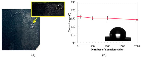
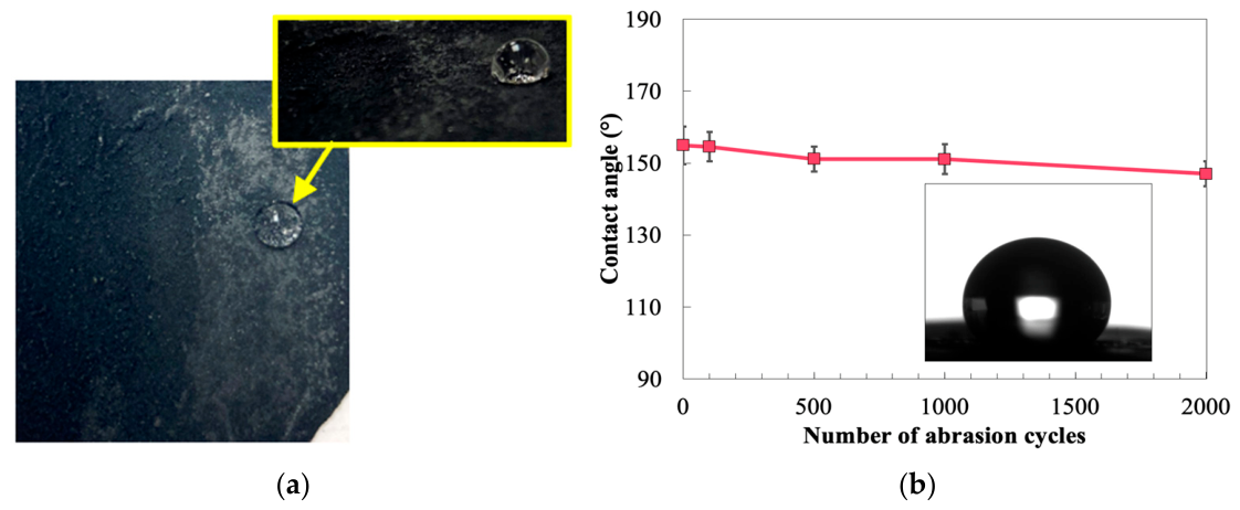
The mechanical robustness of the CNT-modified surface was evaluated using a Taber abrasion test (ASTM D4060) with two CS-10 abrading wheels under controlled loading at 72 rpm for 2000 cycles, producing a visible circular wear track indicating partial removal or deformation of the outermost surface features. As shown in Figure 19, the static water contact angle remained above 150° after 1000 cycles and gradually decreased to approximately 147° after 2000 cycles. However, this is slightly below the conventional superhydrophobicity threshold; water droplets maintained a near-spherical geometry, indicating that a substantial portion of the low-wetting characteristics was preserved.
Figure 19.
Abrasion durability of superhydrophobic surface: (a) surface morphology after 2000 abrasion cycles and (b) corresponding static water contact angle.
This gradual reduction in contact angle is likely associated with partial smoothing of nanoscale surface features generated by the CNT treatment, though sufficient surface roughness remained to sustain strong water-repellent behavior throughout the test, suggesting the CNT-modified surface maintained a significant portion of its functional performance under the laboratory wear conditions investigated. Preservation of water-repellent behavior may be beneficial because increased wetting and prolonged water residence time could promote moisture accumulation on metallized surfaces during service. This evaluation was limited to laboratory-scale abrasion testing and did not include combined environmental aging, UV exposure, cyclic icing, or long-term weathering effects; additional studies involving coupled mechanical and environmental degradation mechanisms would be beneficial for further evaluating long-term stability.
5. Conclusions
This study provides new insights into the synergistic role of nanofillers in improving corrosion resistance and mechanical durability of polymer coatings through enhanced barrier properties and interfacial reinforcement. The present work investigates the feasibility of modifying HVOF-metallized CFRP coatings using a hybrid GNP-C60 nanocomposite coating and a CNT-based surface treatment, demonstrating that combined nanocomposite coating modification and CNT-based surface treatment can improve the adhesion, mechanical performance, abrasion resistance, and barrier-related behavior of HVOF-metallized CFRP coatings while introducing highly water-repellent and anti-icing functionality onto the modified coating surface. Based on the experimental results obtained under laboratory conditions, pull-off adhesion strength increased from approximately 320 to 650 psi (approximately 100%), tensile strength increased by approximately 124% relative to neat epoxy, and abrasion mass loss was reduced by more than 50% relative to neat epoxy, together demonstrating the reinforcing and defect-sealing effect of the hybrid nanofiller system. Electrochemical impedance spectroscopy revealed increased low-frequency impedance and stable capacitive behavior after 200 h of salt spray exposure, indicating improved barrier-related performance. CNT surface treatment transformed the coating surface from hydrophilic behavior to a highly water-repellent state with water contact angles above 155°, extended icing delay, and reduced ice accumulation, with the surface retaining substantial water-repellent functionality after 2000 abrasion cycles (~147°), indicating preliminary durability under laboratory wear conditions. Several limitations should be acknowledged. The present work was conducted as a laboratory-scale feasibility study and did not include long-term environmental aging, cyclic freeze–thaw exposure, UV weathering, or quantitative ice adhesion measurements. Furthermore, the electrochemical evaluation focused on the hybrid nanocomposite coating, while the CNT surface treatment was not included in the EIS assessment. The mechanistic interpretations proposed herein are based primarily on indirect microstructural observations and should therefore be considered preliminary.
Future work should focus on long-term durability assessment, quantitative ice adhesion characterization, environmental aging studies, and additional interfacial characterization to further evaluate the practical applicability of nanocomposite-modified metallized CFRP coatings.
Author Contributions
I.R., X.W. and H.P. designed and conducted this research and wrote the paper under the supervision of Z.L. and edited the paper. All authors have read and agreed to the published version of the manuscript.
Funding
USDOTs (DTPH5616HCAAP03, 693JK318500010CAAP, 693JK31850009CAAP, 693JK32110003POTA, and 693JK32250007CAAP).
Institutional Review Board Statement
Not applicable.
Informed Consent Statement
Not applicable.
Data Availability Statement
Data are contained within the article.
Acknowledgments
The authors gratefully acknowledge the financial support provided by USDOTs. The results, discussion, and opinions reflected in this paper are those of the authors only and do not necessarily represent those of the sponsors.
Conflicts of Interest
The authors declare no conflicts of interest.
References
- Vijayan, D.S.; Sivasuriyan, A.; Devarajan, P.; Stefańska, A.; Wodzyński, Ł.; Koda, E. Carbon fibre-reinforced polymer (CFRP) composites in civil engineering Application—A comprehensive review. Buildings 2023, 13, 1509. [Google Scholar] [CrossRef] [Scilit]
- Rezzoug, A.; Abdi, S.; Kaci, A.; Yandouzi, M. Thermal spray metallisation of carbon fibre reinforced polymer composites: Effect of top surface modification on coating adhesion and mechanical properties. Surf. Coat. Technol. 2018, 333, 13–23. [Google Scholar] [CrossRef] [Scilit]
- Adeleke, S.A.; Caldona, E.B. Plasma Electrolytic Oxidation-Based Superhydrophobic Coatings: Fabrication, Rudiments, and Constraints. J. Coat. Technol. Res. 2025, 22, 17–32. [Google Scholar] [CrossRef] [Scilit]
- Gillet, V.; Aubignat, E.; Costil, S.; Courant, B.; Langlade, C.; Casari, P.; Knapp, W.; Planche, M.P. Development of low pressure cold sprayed copper coatings on carbon fiber reinforced polymer (CFRP). Surf. Coat. Technol. 2019, 364, 306–316. [Google Scholar] [CrossRef] [Scilit]
- Bortolussi, V.; Figliuzzi, B.; Willot, F.; Faessel, M.; Jeandin, M. Electrical conductivity of Metal-Polymer cold spray composite coatings onto carbon fiber-reinforced polymer. J. Therm. Spray Technol. 2020, 29, 642–656. [Google Scholar] [CrossRef] [Scilit]
- Archambault, G.; Jodoin, B.; Gaydos, S.; Yandouzi, M. Metallization of carbon fiber reinforced polymer composite by cold spray and lay-up molding processes. Surf. Coat. Technol. 2016, 300, 78–86. [Google Scholar] [CrossRef] [Scilit]
- Che, H.; Vo, P.; Yue, S. Metallization of carbon fibre reinforced polymers by cold spray. Surf. Coat. Technol. 2017, 313, 236–247. [Google Scholar] [CrossRef] [Scilit]
- Abbas, M.; Smith, G.M.; Munroe, P.R. Microstructural study of HVOF-sprayed Ni particles on a grit-blasted stainless-steel substrate. Surf. Coat. Technol. 2021, 409, 126832. [Google Scholar] [CrossRef] [Scilit]
- Ganesan, A.; Affi, J.; Yamada, M.; Fukumoto, M. Bonding behavior studies of cold-sprayed copper coating on the PVC polymer substrate. Surf. Coat. Technol. 2012, 207, 262–269. [Google Scholar] [CrossRef] [Scilit]
- Odhiambo, J.G.; Li, W.; Zhao, Y.; Li, C. Porosity and its significance in plasma-sprayed coatings. Coatings 2019, 9, 460. [Google Scholar] [CrossRef] [Scilit]
- Semmler, C.; Schwan, W.; Killinger, A. Metallization of carbon fiber-reinforced plastics (CFRP): Influence of plasma pretreatment on mechanical properties and splat formation of atmospheric plasma-sprayed aluminum coatings. Coatings 2024, 14, 1169. [Google Scholar] [CrossRef] [Scilit]
- Tyagi, A.; Murtaza, Q.; Walia, R.S. Evaluation of the residual stress of HVOF sprayed carbon coating after wear testing conditions using ANN coupled taguchi approach. Surf. Topogr. Metrol. Prop. 2021, 9, 35027. [Google Scholar] [CrossRef] [Scilit]
- Lanzutti, A.; Sordetti, F.; Marin, E.; Andreatta, F.; Carabillo, A.; Querini, M.; Porro, S.; Rondinella, A.; Magnan, M.; Fedrizzi, L. The use of thin films as defect sealants to increase the corrosion resistance of thermal spray coatings. Metals 2023, 13, 1778. [Google Scholar] [CrossRef] [Scilit]
- Knuuttila, J.; Sorsa, P.; Mäntylä, T. Sealing of thermal spray coatings by impregnation. J. Therm. Spray Technol. 1999, 8, 249–257. [Google Scholar] [CrossRef] [Scilit]
- Kim, S.; Lee, S.; Kim, I.; Kim, S.; Han, M.; Jang, S. Cavitation and electrochemical characteristics of thermal spray coating with sealing material. Trans. Nonferr. Met. Soc. China 2013, 23, 1002–1010. [Google Scholar] [CrossRef] [Scilit]
- Wei, X.; Dai, F.; Ban, A.; Liu, L.; Li, N.; Zhang, C. Long-term corrosion behavior of flame sprayed al-based coatings after nano-alumina sealing treatment. J. Therm. Spray Technol. 2023, 32, 2157–2169. [Google Scholar] [CrossRef] [Scilit]
- Abdi, J.; Izadi, M.; Bozorg, M. Improvement of anti-corrosion performance of an epoxy coating using hybrid UiO-66-NH2/carbon nanotubes nanocomposite. Sci. Rep. 2022, 12, 10660. [Google Scholar] [CrossRef] [Scilit] [PubMed]
- Yu, M.; Liang, L.; Zhang, Y.; Wang, Z. Fabrication of a durable anti-icing composite coating based on polyurethane elastomer and silica nanoparticles. Mater. Res. Express 2022, 9, 55504. [Google Scholar] [CrossRef] [Scilit]
- Wang, X.; Lin, Z. A novel high-performance coating with hybrid nanofiller reinforcement for superior self-cleaning, anti-icing, and corrosion resistance properties. J. Build. Eng. 2023, 80, 107993. [Google Scholar] [CrossRef] [Scilit]
- Wang, X.; Lin, Z. Morphologic and synergistic effects of GNP/NS binary-filler-based multifunctional coatings with robust anti-corrosion and hydrophobic properties. Prog. Org. Coat. 2021, 157, 106286. [Google Scholar] [CrossRef] [Scilit]
- Hussain, Z.; Wang, X.; Riaz, I.; Lin, Z.; Nie, W.; Lin, Y.; Tao, C.; Huang, Y. Experimental and multi-scale simulation evaluation of nanoclay/nanosilica epoxy coatings for enhanced corrosion protection of structural steel. Corros. Sci. 2026, 260, 113574. [Google Scholar] [CrossRef] [Scilit]
- Wang, X.; Cao, Q.; Tang, F.; Pan, H.; Chen, X.; Lin, Z. Mechanical properties and corrosion behavior of dual-filler-epoxy-coated steel rebar under a corrosive environment. Coatings 2023, 13, 604. [Google Scholar] [CrossRef] [Scilit]
- Zhong, M.; Zhang, Y.; Li, X.; Wu, X. Facile fabrication of durable superhydrophobic silica/epoxy resin coatings with compatible transparency and stability. Surf. Coat. Technol. 2018, 347, 191–198. [Google Scholar] [CrossRef] [Scilit]
- Zhang, F.; Qian, H.; Wang, L.; Wang, Z.; Du, C.; Li, X. Superhydrophobic carbon nanotubes/epoxy nanocomposite coating by facile one-step spraying. Surf. Coat. Technol. 2018, 341, 15–23. [Google Scholar] [CrossRef] [Scilit]
- Hussain, Z.; Riaz, I.; Wang, X.; Lin, Z.; Nie, W.; Huang, Y. Corrosion-protective nanoclay reinforced epoxy coating for structural applications: Mechanics and molecular dynamics. Constr. Build. Mater. 2026, 526, 146330. [Google Scholar] [CrossRef] [Scilit]
- Shen, Y.; Wu, Y.; Tao, J.; Zhu, C.; Chen, H.; Wu, Z.; Xie, Y. Spraying fabrication of durable and transparent coatings for anti-icing application: Dynamic water repellency, icing delay, and ice adhesion. ACS Appl. Mater. Interfaces 2018, 11, 3590–3598. [Google Scholar] [CrossRef] [Scilit] [PubMed]
- Mehmood, A.; Ur-Rehman, Z.; Altaf, M.; Ashraf, R.S.; Sohail, M.; Isab, A.A. NiRu0.3Se Nanoparticles In Situ Grown on Reduced Graphene: Synthesis and Electrocatalytic Activity in the Oxygen Evolution Reaction. ChemistrySelect 2021, 6, 502–510. [Google Scholar] [CrossRef] [Scilit]
- Adeleke, S.A. The Effects of Different Bioceramics-Incorporated Oxide Films on Titanium Implant by Plasma Electrolytic Oxidation. J. Mater. Res. 2022, 37, 4348–4359. [Google Scholar] [CrossRef] [Scilit]
- Wang, X.; Qi, X.; Lin, Z.; Battocchi, D. Graphene-Reinforced Composites as Protective Coatings for Oil and Gas Pipelines. Nanomaterials 2018, 8, 1005. [Google Scholar] [CrossRef] [Scilit] [PubMed]
- Lau, K.K.S.; Bico, J.; Teo, K.B.K.; Chhowalla, M.; Amaratunga, G.A.J.; Milne, W.I.; McKinley, G.H.; Gleason, K.K. Superhydrophobic carbon nanotube forests. Nano Lett. 2003, 3, 1701–1705. [Google Scholar] [CrossRef] [Scilit]
- Cassie, A.B.D.; Baxter, S. Wettability of porous surfaces. Trans. Faraday Soc. 1944, 40, 546–551. [Google Scholar] [CrossRef] [Scilit]
- Rajitha, K.; Mohana, K.N.S. Synthesis of graphene oxide-based nanofillers and their influence on the anticorrosion performance of epoxy coating in saline medium. Diam. Relat. Mater. 2020, 108, 107974. [Google Scholar] [CrossRef] [Scilit]
- Rajitha, K.; Mohana, K.N.S.; Mohanan, A.; Madhusudhana, A.M. Evaluation of anti-corrosion performance of modified gelatin-graphene oxide nanocomposite dispersed in epoxy coating on mild steel in saline media. Colloids Surf. A Physicochem. Eng. Asp. 2020, 587, 124341. [Google Scholar] [CrossRef] [Scilit]
- Tuteja, A.; Duxbury, P.M.; Mackay, M.E. Multifunctional nanocomposites with reduced viscosity. Macromolecules 2007, 40, 9427–9434. [Google Scholar] [CrossRef] [Scilit]
- Jain, S.; Goossens, J.G.; Peters, G.W.; van Duin, M.; Lemstra, P.J. Strong decrease in viscosity of nanoparticle-filled polymer melts through selective adsorption. Soft Matter 2008, 4, 1848–1854. [Google Scholar] [CrossRef] [Scilit]
- Washburn, E.W. The dynamics of capillary flow. Phys. Rev. 1921, 17, 273–283. [Google Scholar] [CrossRef] [Scilit]
- Ka Wei, K.; Leng, T.P.; Keat, Y.C.; Osman, H.; Sullivan, M.; Hong, V.C.; Rasidi, M.S.M. Comparison Study: The Effect of Unmodified and Modified Graphene Nanoplatelets (GNP) on the Mechanical, Thermal, and Electrical Performance of Different Types of GNP-Filled Materials. Polym. Adv. Technol. 2021, 32, 3588–3608. [Google Scholar] [CrossRef] [Scilit]
- Bragaglia, M.; Paleari, L.; Lamastra, F.R.; Puglia, D.; Fabbrocino, F.; Nanni, F. Graphene Nanoplatelet, Multiwall Carbon Nanotube, and Hybrid Multiwall Carbon Nanotube–Graphene Nanoplatelet Epoxy Nanocomposites as Strain-Sensing Coatings. J. Reinf. Plast. Compos. 2021, 40, 632–643. [Google Scholar] [CrossRef] [Scilit]
- Shahzadeh, N.; Hevus, I.; Bahr, J.; Webster, D.C. Mechanically Robust Non-Isocyanate Polyurethane Coatings with Scale-Independent Anti-Icing Performance. Chem. Eng. J. 2025, 524, 169395. [Google Scholar] [CrossRef] [Scilit]
- Adeleke, S.A.; Ramesh, S.; Bushroa, A.R.; Ching, Y.C.; Sopyan, I.; Maleque, M.A.; Sutharsini, U. The Properties of Hydroxyapatite Ceramic Coatings Produced by Plasma Electrolytic Oxidation. Ceram. Int. 2018, 44, 1802–1811. [Google Scholar] [CrossRef] [Scilit]
- ASTM D638-22; Standard Test Method for Tensile Properties of Plastics. ASTM International: West Conshohocken, PA, USA, 2022.
- ASTM D4060-19; Standard Test Method for Abrasion Resistance of Organic Coatings by the Taber Abraser. ASTM International: West Conshohocken, PA, USA, 2019.
- ASTM D4541-22; Standard Test Method for Pull-Off Strength of Coatings Using Portable Adhesion Testers. ASTM International: West Conshohocken, PA, USA, 2022.
Disclaimer/Publisher’s Note: The statements, opinions and data contained in all publications are solely those of the individual author(s) and contributor(s) and not of MDPI and/or the editor(s). MDPI and/or the editor(s) disclaim responsibility for any injury to people or property resulting from any ideas, methods, instructions or products referred to in the content. |
© 2026 by the authors. Licensee MDPI, Basel, Switzerland. This article is an open access article distributed under the terms and conditions of the Creative Commons Attribution (CC BY) license.