


Abstract
To address the issues of high cutting temperatures and severe tool wear during titanium alloy machining, this study proposes a hybrid surface modification strategy combining micro-textures and multicomponent titanium nitride (TiN)-based coatings on cemented carbide tools. Using YG8 cemented carbide as the substrate, micro-dimple textures were fabricated by fiber laser, and three coatings with different architectures (TiAlSiN, TiSiN/TiAlN, and TiSiN/TiAlSiN/TiAlN) were deposited via multi-arc ion plating technology. Based on a two-factor (texture diameter and texture spacing) and three-level orthogonal experiment, the evolution behaviors of surface morphology, phase composition, and mechanical properties of the textured multicomponent TiN-based coatings were systematically characterized and comparatively analyzed. The results reveal that: compared to the monolithic-structured TiAlSiN coating, the TiSiN/TiAlSiN/TiAlN and TiSiN/TiAlN composite coatings with multilayered composite structures can effectively relieve the residual stress inside the film–substrate system, and significantly suppress the phenomena of coating cracking and localized spallation caused by irregular protrusions of the recast layer at the micro-texture edges. X-ray diffraction (XRD) and crystallite size analyses indicate that the amorphous Si3N4 phase promoted by the Si element in the composite coatings effectively impedes the growth of TiN columnar crystals, achieving significant grain refinement. Mechanical property tests confirm that the existence of multicomponent composite interfaces effectively hinders dislocation movement. Among them, the textured TiSiN/TiAlSiN/TiAlN composite coating exhibits the optimal comprehensive performance; its microhardness, nanohardness, and H/E ratio (characterizing the resistance to plastic deformation) are increased by 17.94%, 8%, and approximately 45%, respectively, compared to those of the textured TiAlSiN coating. This study deeply elucidates the synergistic strengthening and toughening mechanisms between micro-texture parameters and the internal structures of the coatings, providing important theoretical guidance and experimental data support for the surface design of long-lifespan tools oriented towards the high-efficiency machining of titanium alloys.
1. Introduction
With the rapid development of aerospace, medical devices, and high-end equipment manufacturing industries, titanium alloys are widely applied in these fields due to their excellent mechanical properties, corrosion resistance, and high-temperature resistance. However, the high strength and low thermal conductivity of titanium alloys lead to elevated cutting forces and cutting temperatures during the machining process, resulting in severe tool wear. This directly compromises the surface machining quality of workpieces, leading to reduced production efficiency and increased machining costs. Previous studies have demonstrated [1,2,3] that introducing micro-textures onto the surface of cemented carbide tools can effectively reduce the tool–chip contact area and capture impurities such as abrasive particles and chips. This significantly lowers the cutting force and temperature, thereby preliminarily improving the cutting performance of the tools. Nevertheless, under complex high-temperature and high-pressure cutting environments [4], a monolithic surface micro-texture is prone to extrusion deformation or rapid flattening. Lacking sufficient high-temperature oxidation resistance and thermal insulation performance, it is difficult to maintain long-term anti-friction and wear-resistant effects [5]. To address the limitations of single-component coatings (e.g., TiN)—which exhibit poor oxidation resistance and rapid hardness degradation during high-temperature cutting—multicomponent coatings demonstrate more pronounced advantages owing to their exceptional solid-solution strengthening effects and their capability to form protective oxide films at elevated temperatures. Therefore, preparing high-performance multicomponent coatings on the tool surface can substantially enhance the rake face hardness. Utilizing their robust film–substrate adhesion and their synergistic mechanism with surface micro-textures can effectively mitigate tool friction and wear under severe cutting conditions [6,7,8].
Zhang et al. [9] deposited nano/micro TiAlSiN coatings on M2 high-speed steel tools using a cathodic arc deposition system and investigated their properties, demonstrating that the coated tools exhibited excellent cutting performance. Liu [10] employed uncoated and AlCrSiN-coated cemented carbide tools to turn Ti-6Al-4V titanium alloys; the wear evolution results revealed a faster wear rate for the uncoated tools. Li [11] fabricated TiAlTaCrZrN coatings on tool surfaces via direct current (DC) magnetron sputtering and found that the cutting distance of TiAlTaCrZrN-coated tools increased by 175% compared to TiAlN-coated ones during titanium alloy machining. Liu [12] prepared Ti-Si-C coated tools by magnetron sputtering for dry cutting tests on quenched steel, concluding that the Ti-Si-C coating effectively reduced tool wear. Miao [13] developed AlCrN-coated tools for dry milling tests on Ti-6Al-4V; compared with uncoated counterparts, the AlCrN-coated tools exhibited a reduced bending moment during the milling process.
Han et al. [14] indicated that coatings and micro-textures can synergistically enhance tool performance, though their microscopic strengthening mechanisms require further systematic investigation. Their study elucidated the regulatory rules of hybrid processes on cemented carbide surface properties through various characterization methods, verifying that micro-texture pretreatment can significantly optimize the microstructure, hardness, and wear resistance, and that the fractal dimension can quantitatively evaluate wear damage. Shi et al. [15] investigated the synergistic mechanism between laser micro-textures and diamond-like carbon (DLC) coatings on the tribological properties of SUS304 stainless steel. Through friction experiments and finite element simulations, they observed that a 45° inclined groove texture combined with a DLC coating significantly reduced interfacial residual stress, stabilized the friction coefficient, and enhanced wear resistance, providing a theoretical basis for wear-resistant surface design. Liu et al. [16] explored the influence of laser-machined micro-textures on the wear resistance of AlCrN coatings on Ti-6Al-4V titanium alloy surfaces. Through morphology analysis, scratch tests, and tribological evaluations, they discovered that a micro-texture with a 150 μm diameter and a 10% area density could significantly optimize the coating surface condition and improve film–substrate adhesion. This increased the wear resistance of the AlCrN coating to 1.697 times that of untextured samples, offering technical support for optimizing wear-resistant coatings on titanium alloy surfaces. Liu et al. [17] investigated the synergistic mechanism of AlCrN coatings and micro-textures on the mechanical and cutting performance of cemented carbide tools. By fabricating micro-textures on the rake face of WC/Co cemented carbide tools prior to AlCrN deposition, they identified the optimal parameter range for the micro-textures. Dry cutting experiments on Ti-6Al-4V titanium alloy demonstrated that this composite structure improved the mechanical properties of the coating and the anti-adhesion of the tool, slightly reduced the cutting force, and significantly decreased surface roughness and tool wear, providing theoretical guidance for the optimal design of textured coatings on tool surfaces.
In summary, extensive research has proven that the preparation processes of both multicomponent coatings and surface micro-textures have positive effects on tool performance. Specifically, hybrid coating processes are highly beneficial for extending tool service life during cutting and reducing post-machining tool wear. However, few studies have addressed the combined effects of micro-texture parameters and the types of multicomponent coatings on the surface microstructural characteristics of tools. Addressing this gap, this study prepares micro-textures with varying geometric parameters and different types of multicomponent TiN-based coatings on cemented carbide substrates. The objective is to investigate the effects of different micro-texture geometric parameters and multicomponent TiN-based coating types on surface microstructural characteristics, thereby making a definitive contribution to the surface performance enhancement of cutting tools.
2. Establishment of an Experimental Platform for the Surface Microstructural Characteristics of Textured Multicomponent TiN-Based Coated Cemented Carbides
2.1. Structural Analysis of Multicomponent TiN-Based Coatings
The introduction of Al and Si elements into TiN-based coatings forms the quaternary TiAlSiN coating, which exhibits excellent hardness and high-temperature thermal stability. However, when the TiAlSiN coating is bonded to a metallic substrate, the amorphous Si3N4 phase formed by the Si element hinders the chemical bonding and wetting process between Ti and the substrate, thereby weakening the interfacial adhesion strength between the film and the substrate. Furthermore, the mismatch in thermal expansion coefficients between the coating and the substrate, along with the grain growth process, generates significant residual stress, which further exacerbates internal failure and spallation of the coating [18].
In this study, YG8 cemented carbide with a chemical composition of 92% WC and 8% Co was selected as the substrate material for experimental analysis. The thermal expansion coefficient of YG8 cemented carbide is (5.0~6.0) × 10−6 K−1, whereas the average value for the TiAlN structure in room-temperature experiments is 8.0 × 10⁻⁶ K−1, and that for the TiAlSiN structure ranges from 8.0 × 10⁻⁶ to 9.0 × 10⁻⁶ K−1 [19,20]. Therefore, compared to the TiAlSiN structure, the TiAlN structure exhibits a smaller difference in thermal expansion coefficient relative to the YG8 cemented carbide. Simultaneously, both the YG8 cemented carbide and the TiAlN structure possess elastic moduli of 400~500 GPa [21], indicating highly similar values. When the structure of the coating adjacent to the substrate side closely matches the substrate in both thermal expansion coefficient and elastic modulus, the internal residual stress between the coating and the substrate is attenuated, thereby enhancing the overall film–substrate adhesion performance [22]. In summary, utilizing TiAlN as the internal structure of the multicomponent TiN-based coating adjacent to the substrate not only prevents the degradation of adhesion performance caused by the formation of an amorphous structure by Si, but also reduces the loose spallation of the inner coating structure induced by high-temperature oxidation.
A high surface Al content in multicomponent TiN-based coatings can induce embrittlement, rendering the coating prone to cracking or spallation under surface impact or wear. When the outermost surface structure is composed of TiSiN, the wear resistance and high-temperature tolerance of the coating surface can be significantly enhanced. The structure wherein the amorphous Si3N4 phase envelops TiN grains impedes dislocation occurrence between grains, and the amorphous structure formed by Si effectively suppresses crack propagation [23,24]. Therefore, TiSiN should be selected as the outermost surface structure of the coating.
Serving as an intermediate transition section, the TiAlSiN structure facilitates the elemental transition between the TiAlN and TiSiN structures. The configuration in which amorphous silicon nitride compounds envelop TiAlN columnar crystals also bolsters the overall resistance to deformation of the coating. Consequently, TiAlSiN should be employed as the intermediate transition structure of the coating.
Based on the aforementioned rationales, the monolithic TiAlSiN coating, the TiSiN/TiAlN composite coating, and the TiSiN/TiAlSiN/TiAlN composite coating were selected for subsequent experiments evaluating the surface microstructural properties and tribological performance of the textured multicomponent TiN-based coated cemented carbides. The specific types and architectures of the multicomponent TiN-based coatings are illustrated in Figure 1.
Figure 1.
Types of multicomponent TiN-based coatings and their structures.
2.2. Preparation of Textured Multicomponent TiN-Based Coatings on Cemented Carbide Surfaces
2.2.1. Preparation of Micro-Textures on Cemented Carbide Surfaces
YG8 cemented carbide was selected as the substrate material for the specimens. As detailed in Table 1, the high hardness and robust toughness of this specific grade make it highly suitable as a tool material for machining titanium alloys. The specimens were prepared as cylindrical pins with a height of 10 mm and a diameter of 5 mm.
Table 1.
Material properties of YG8 cemented carbide [25].
Micro-textures were fabricated on the upper end face of the cylindrical pins using a Zhengtian ZTQ-50 fiber laser (Beijing, China). Relevant studies have demonstrated [26] that during tool–chip friction on the rake face, micrometer-scale micro-dimple textures exhibit a more significant effect on improving surface tribological performance compared to micro-textures of other geometries. Therefore, micro-dimple textures were selected for fabrication in this study. The controllable laser processing parameters of the fiber laser include laser power, scanning speed, and the number of scanning passes. The specific laser parameters employed for the fabrication of surface micro-textures on the specimens were set as follows: a laser power of 45 W, a scanning speed of 1700 mm/s, and 8 scanning passes [27]. Under these optimized laser parameters, both the tribological performance and wear resistance of the surface micro-textures are demonstrably enhanced. Schematic diagrams of the YG8 cemented carbide cylindrical pin specimen, the architecture of the fiber laser system, and the laser fabrication process of the micro-textures are illustrated in Figure 2. During the texturing process, laser energy is directed into the surface of the cemented carbide material from the center of the laser spot along a pre-programmed scanning path. The localized absorption of this laser energy induces melting and vaporization in the surface region, thereby achieving the targeted removal of the surface material.
Figure 2.
Schematic diagram of the cemented carbide cylindrical pin specimen, the laser fabrication equipment, and the micro-texture fabrication process.
2.2.2. Preparation of Multicomponent TiN-Based Coatings
Upon completion of the micro-texture fabrication on the cemented carbide cylindrical pins, three types of multicomponent TiN-based coatings were deposited onto the textured surfaces via multi-arc ion plating technology, utilizing specialized equipment provided by Tiangong Tools Co., Ltd. (Harbin, China).
Upon completion of the deposition of the three coatings, the coated specimens were sectioned via wire electrical discharge machining (WEDM). A Hitachi SU5000 scanning electron microscope (SEM) (Naka, Japan) was utilized to observe the cross-sectional morphology of the coatings, and energy-dispersive X-ray spectroscopy (EDS) line scanning was employed to analyze the elemental distribution trends across the cross-sections. The obtained experimental results are illustrated in Figure 3. For the distinct structural regions of the TiSiN/TiAlSiN/TiAlN and TiSiN/TiAlN composite coatings, SEM selected-area mapping was conducted to acquire the elemental mass fractions and atomic percentages for verification, with the results presented in Table 2 and Table 3.
Figure 3.
Cross-sectional morphology and elemental distribution of the three types of multicomponent TiN-based coatings.
Table 2.
Elemental mass fractions and atomic percentages of the TiSiN/TiAlSiN/TiAlN composite coating.
Table 3.
Elemental mass fractions and atomic percentages of the TiSiN/TiAlN composite coating.
In this study, the total thickness of the prepared coatings ranges from approximately 2.5 to 3 μm. Within the TiSiN/TiAlSiN/TiAlN composite coating, the proportions of the TiSiN, TiAlSiN, and TiAlN layers are approximately 20%, 30%, and 50%, respectively. For the TiSiN/TiAlN composite coating, the TiSiN and TiAlN layers account for approximately 25% and 75%, respectively. As indicated by Figure 3, Table 2 and Table 3, the contents of Ti and Si elements in the TiSiN/TiAlSiN/TiAlN composite coating exhibit an increasing trend from the internal structure adjacent to the substrate towards the surface layer, whereas the Al content displays a decreasing trend. Similarly, in the TiSiN/TiAlN composite coating, the Al content progressively decreases from the internal structure to the outer layer, while the Si content gradually increases from the inside to the outside. Conversely, the constituent elements within the monolithic TiAlSiN coating are distributed uniformly throughout.
The TiSiN/TiAlSiN/TiAlN composite coating, the TiSiN/TiAlN composite coating, and the TiAlSiN coating were deposited onto the cemented carbide specimens featuring surface micro-textures. The resulting appearances after deposition are illustrated in Figure 4.
Figure 4.
Ultra-depth of field microscope images of the surfaces of the three types of textured coated cemented carbide specimens.
2.3. Testing Apparatus and Scheme Design for Microstructural Characteristics
2.3.1. Experimental Scheme Design
For the surface microstructural characteristics experiments, the textured coated cemented carbide specimens were divided into three groups based on the coating type: the TiSiN/TiAlSiN/TiAlN composite coating (Group A), the TiSiN/TiAlN composite coating (Group B), and the TiAlSiN coating (Group C). Previous findings from our research group [25] have demonstrated that the geometric parameters of micro-textures (e.g., micro-texture diameter and micro-texture spacing) significantly influence the surface properties of textured coated specimens. Therefore, for each group of textured coated cemented carbide specimens featuring TiN-based coatings (Groups A, B, and C), an L9(34) orthogonal array design with two factors, three levels, and interactive effects was formulated based on their micro-texture geometric parameters. The two principal factors are texture diameter (D) and texture spacing (L), with the interaction defined between D and L. The factors and their corresponding levels for the orthogonal experiment are detailed in Table 4. The specific value ranges for the levels of texture diameter and texture spacing were determined based on the team’s preliminary research. Consequently, a total of 27 specimens were prepared across the three groups. The detailed orthogonal experimental design array for each group of specimens is presented in Appendix A Table A1.
Table 4.
Orthogonal experimental array with two factors, three levels, and interactive effects.
2.3.2. Testing Apparatus for Microstructural Characteristics
Phase structure analysis of the surfaces of the three groups of textured coated cemented carbide specimens was conducted using an X’Pert-Pro MPD X-ray diffractometer (XRD) (Almelo, The Netherlands). The diffractometer utilized a Cu Kα radiation target and operated in continuous scanning mode. The scanning step size was set to 0.026°, with a dwell time of 35 s per step. The diffraction angle (2) range was selected from 20° to 90°, with the K-Alpha1 wavelength at 1.540598 Å and the K-Alpha2 wavelength at 1.544426 Å. The XRD equipment is illustrated in Figure 5. The experimental X-ray diffraction data were imported into MDI Jade 6 software to generate XRD patterns, thereby facilitating the phase structure analysis of the specimen surfaces.
Figure 5.
Experimental platform for microstructural characteristics testing.
A Hitachi SU5000 scanning electron microscope (SEM) was employed to observe the surface morphology of the three groups of textured coated cemented carbide specimens. Additionally, an integrated energy-dispersive X-ray spectrometer (EDS) was utilized to perform elemental area mapping on the specimen surfaces, analyzing the distribution of constituent elements within a single micro-texture and its surrounding region. The SEM equipment and its corresponding observation results are also shown in Figure 5.
Microhardness testing of the surfaces of the three types of textured coated cemented carbide specimens was conducted using an HVS-1000Z micro-Vickers hardness tester (Laizhou, China). The indenter load applied in the experiment was 9.8 N, with a dwell time of 15 s before unloading. The surface indentations on the specimens were observed through the microscope lens attached to the hardness tester. The lengths of the indentation diagonals, d1 and d2, were measured. The mean diagonal length, d, calculated as half the sum of d1 and d2, was then substituted into Equation (1) to obtain the micro-Vickers hardness value under the applied load. Three indentation points were randomly selected in the region surrounding the micro-textures to measure the hardness values, and the average value was taken as the final experimental result. The micro-Vickers hardness tester, its testing interface, and a schematic of the test are presented in Figure 5.
A Bruker Hysitron TI 980 nanoindenter (Eden Prairie, MN, USA) was utilized to measure the nanohardness and elastic modulus of the surfaces of the three groups of textured coated cemented carbide specimens. Based on the load and displacement parameters extracted from the resulting test curves, the nanohardness and elastic modulus at each indentation point were determined. The applied peak load was 8000 μN, corresponding to an indentation depth of approximately 150 nm, which is significantly less than 270 nm (10% of the coating thickness). Consequently, the indenter solely induced plastic deformation within the surface layer of the coating, ensuring that the underlying YG8 cemented carbide substrate did not influence the measurement results. The durations for the loading, holding, and unloading phases were set to 5 s each. Three indentation points were tested on the surface of each specimen, and the average of the measured values was calculated to yield the final test result.
3. Comparative Analysis of Surface Micro-Morphologies of Textured Multicomponent TiN-Based Coated Cemented Carbides
On the surface of the cemented carbide substrate, the central region of the micro-texture experiences an increased energy density due to the concentrated overlapping of the laser spot. Consequently, the volume of material removed in the central region is significantly greater than that in the surrounding area, resulting in a deeper depression in the center compared to the periphery. Therefore, the longitudinal cross-sectional profile of the micro-texture in the cemented carbide specimen resembles a Gaussian curve, as illustrated in Figure 6a. During the laser fabrication process, the texturing region experiences significant thermal gradients. This uneven surface temperature distribution leads to lower surface tension in the molten metal within the high-temperature central region and higher surface tension in the relatively lower-temperature peripheral region. This surface tension gradient within the molten metal induces the Marangoni effect. Driven by this effect and the recoil pressure, the molten metal flows from the central laser-irradiated zone towards the edge region (as shown in Figure 6b), ultimately forming a recast layer at the periphery of the micro-texture upon cooling [28]. Under the influence of the strong recoil gas flow, a portion of the molten metal spatters onto the cemented carbide surface outside the laser fabrication zone, forming surface spatter particles [29]. The morphologies of the recast layer and the spatters associated with the micro-textures on the cemented carbide surface are depicted in Figure 6c. As the micro-texture diameter increases, the area of an individual micro-texture enlarges, leading to a corresponding increase in the volume of molten material on the cemented carbide surface. Consequently, more molten material flows towards the periphery of the micro-texture, resulting in a proportional increase in the area of the recast layer at the edge. Furthermore, during the laser fabrication of micro-textures on the cemented carbide surface, internal thermal stresses are induced within the material due to extreme temperature gradients. When these internal thermal stresses exceed the interfacial bonding strength between the WC phase and the Co binder phase, cracks are initiated between these distinct microstructural phases.
Figure 6.
Surface morphological characteristics and formation mechanisms of the micro-textures.
Figure 7, Figure 8 and Figure 9 present the elemental distribution results obtained via EDS area mapping on the surfaces of the textured multicomponent TiN-based coatings (specifically, the surfaces of the textured TiSiN/TiAlSiN/TiAlN composite coated, textured TiSiN/TiAlN composite coated, and textured TiAlSiN coated cemented carbide specimens). Overall, the constituent elements are distributed uniformly across the textured coating surfaces, with the contents of Ti and N being notably higher than those of the other elements. The Al content on the surface of the textured TiAlSiN coating is relatively high. Due to the inherently low amount of Si introduced into the coatings, the Si content detected in the EDS results for all three types of specimens is lower than that of Ti, N, and Al. The WC phase is predominantly localized beneath the coating layer, and the oxidation reactions induced during the laser fabrication process are primarily confined to the substrate region; consequently, the detected contents of W, C, and O are relatively low. Finally, Co, which serves as the binder for the YG8 cemented carbide substrate, exhibits the lowest content in the EDS mapping results.
Figure 7.
Elemental distribution of the textured TiSiN/TiAlSiN/TiAlN composite coating on the surface of specimen A2.
Figure 8.
Elemental distribution of the textured TiSiN/TiAlN composite coating on the surface of specimen B2.
Figure 9.
Elemental distribution of the textured TiAlSiN coating on the surface of specimen C2.
Coating defects exist on the surfaces of the textured TiN-based coated cemented carbide specimens (i.e., the TiSiN/TiAlSiN/TiAlN composite coating, the TiSiN/TiAlN composite coating, and the TiAlSiN coating). The primary forms of these defects include droplets, flake-like protrusions, craters, uneven deposition, and delamination. The defect morphologies on the surfaces of the three types of textured TiN-based coatings are illustrated in Figure 10. The formation of droplets on the coating surface is attributed to the evaporation of large particles from the target material, which form a molten pool on the substrate surface and subsequently cool and solidify. Craters are primarily formed when droplets detach from the substrate surface due to stress accumulation during the coating grain growth process. Flake-like protrusions occur because the coating grains, after nucleation, are subjected to thermal stresses during the deposition process, causing them to bulge outward. The spatter particles on the specimen surface can be distinguished from the coating defects based on the W-rich regions shown in Figure 7, Figure 8 and Figure 9, where the areas with concentrated W element correspond to the spatter particles.
Figure 10.
Surface and coating defect morphologies of the three types of textured TiN-based coatings.
According to Figure 10, the phenomenon of coating peeling primarily occurs on the surface of the micro-texture recast layer of the textured TiAlSiN composite coatings (Group C specimens). The irregular protrusions of the micro-texture recast layer reduce the effective bonding area between the coating and the micro-texture edges. Consequently, significant localized thickness variations in the coating appear at these sharp edges, which easily leads to internal stress concentration and causes the coating to peel along the edges of the texture recast layer. In contrast, non-uniform coating deposition is mainly observed on the flat surfaces of the Group C specimens, a phenomenon primarily attributed to the accumulation of internal stress during the grain growth process of the coating.
The comparison of the surface morphologies of the textured TiN-based coated cemented carbide specimens in Figure 10 demonstrates that the surfaces of the textured TiSiN/TiAlSiN/TiAlN and TiSiN/TiAlN composite coatings are generally smooth. Neither coating delamination nor uneven deposition is evident on these surfaces. The primary reason is that the composite coating structure, comprising multiple compounds, can effectively reduce internal stresses. Furthermore, the modulus mismatch between the TiAlN compound and the cemented carbide substrate is minimal, and the TiSiN compound possesses a highly dense structure; both factors effectively mitigate the cracking induced by localized variations in coating thickness.
Coating defects, surface spatter particles, surface cracks at the edges of micro-textures, and coating delamination on the specimen surfaces compromise surface integrity, thereby degrading the morphological quality and adversely affecting the relevant surface properties of the specimens. Therefore, in this section, Image-Pro Plus 6.0 software is utilized to quantitatively characterize these phenomena on the specimen surfaces, aiming to investigate the effects of different TiN-based coating types and micro-texture geometric parameters on the surface micro-morphological quality.
First, both the coating defects (such as droplets, flake-like protrusions, and craters) and the spatter particles on the specimen surfaces exhibit distinct particulate characteristics. Consequently, the particle analysis function of the Image-Pro Plus software is employed to process the SEM images of the specimen surfaces [30]. The area fractions of the coating defects and spatter particles in the images are calculated for different specimens, thereby characterizing the distribution density of these defects and spatters on the specimen surfaces.
As illustrated in Figure 11, the calculation procedure for the area occupancy of coating defects and splatters is as follows: Initially, the SEM images are calibrated for scale and converted into 8-bit grayscale images. Due to the distinct low-gray-level characteristics of defect regions compared to the intact coating, a grayscale threshold range of 0–100 is set for binarization to extract the target features. Subsequently, the “Count/Size” function of the Image-Pro Plus software is utilized, incorporating the target area occupancy (Per Area) as the criterion. By defining a ratio range of 0–0.1, artifacts such as large-area edge recast layers are automatically excluded. Finally, the actual area occupancy of the coating defects is calculated and output as the result. As shown in Figure 11c, the calculation process for the area fraction of the coating defects and spatter particles on the specimen surface is expressed by Equation (2).
where A1 represents the area of coating defects and spatter particles on the specimen surface (in μm2), and A0 denotes the total image area (in μm2).
Figure 11.
Calculation procedure for the area fraction of coating defects and spatter particles in SEM images.
For the cracks present at the edges of the micro-textures on certain specimen surfaces, Image-Pro Plus software is employed to measure the crack density at the micro-texture edges, thereby quantitatively characterizing the crack distribution along these edges. Since the coating delamination phenomenon exclusively occurs at the micro-texture edges of the textured TiAlSiN coated cemented carbide specimens, only the coating delamination density at the micro-texture edges of the Group C specimens is measured. This measurement is utilized to characterize the extent of coating delamination at the texture edges for the various specimens within Group C.
The calculation procedure for these features in the SEM images is illustrated in Figure 12. Initially, the scale bar of the SEM image is calibrated. By utilizing the “Irregular AOI” function of the software, the overall contour of the micro-texture is outlined, and the overall contour area of the outlined individual micro-texture is calculated, as shown in Figure 12b. Subsequently, the crack length on the surface of the recast layer at the micro-texture edges, as well as the coating delamination length on the surface of the recast layer at the micro-texture edges for Group C, are measured. Finally, the calculation results for the crack distribution and the degree of coating delamination of the specimens are obtained using Equations (3) and (4).
where A2 represents the area of a single micro-texture (in μm2); L0 represents the total measured length of surface cracks, and L1 denotes the total measured length of surface coating delamination, with both L0 and L1 expressed in μm.
Figure 12.
Calculation procedure for the crack density and coating delamination density at micro-texture edges.
The quantitative characterization results for the area fractions of coating defects and spatter particles, the crack distribution at micro-texture edges, and the extent of coating delamination on the surfaces of the textured multicomponent TiN-based coated cemented carbide specimens are presented in Appendix A Figure A1.
Based on the quantitative characterization results of the surface morphological quality of the specimens shown in Appendix A Figure A1, the area fractions of coating defects and spatter particles are more significantly influenced by the type of TiN-based coating, whereas the effect of the geometric parameters of the substrate micro-textures (micro-texture diameter and micro-texture spacing) is not distinct. The composite structure of the coatings in the Group A and Group B specimens (TiAlN/TiAlSiN/TiSiN and TiAlN/TiSiN) is conducive to enhancing structural stability [31]. In contrast, the internal residual stress within the Group C coating (TiAlSiN) is relatively large. Therefore, the number of surface defects on the Group A and Group B coatings is lower compared to that on the Group C coating. Furthermore, the Group C coating is more sensitive to irregularities on the substrate surface, making it more prone to accumulating into larger-area surface defects around the spatter particles.
The cracks in the Group A, Group B, and Group C specimens are primarily generated during the laser fabrication process of the micro-textures; therefore, their density is significantly affected by the substrate micro-texture diameter. When the micro-texture diameter is larger, the laser energy applied during the fabrication of a single micro-texture is higher, resulting in an increased thermal gradient between the interior and exterior of the specimen. Consequently, the thermal stress at the micro-texture edges intensifies. When this thermal stress exceeds the interfacial bonding strength between the WC phase and the Co binder phase, the cracking of the recast layer is exacerbated, leading to a higher crack density at the micro-texture edges.
The coating delamination at the micro-texture edges in the Group C specimens is primarily caused by the irregular protrusions of the recast layer. Because the TiAlSiN coating lacks the internal stress buffering provided by a composite structure, its morphology is more sensitive to the adverse effects brought about by the increased area of the recast layer at the micro-texture edges. At the maximum level of the micro-texture diameter, the area of the recast layer at the edge of an individual micro-texture is relatively large. This enhances the stress concentration effect experienced by the TiAlSiN coating at the substrate near the micro-texture edges, thereby resulting in more severe coating delamination. Therefore, the coating delamination density is significantly influenced by variations in the substrate micro-texture diameter.
4. Comparative Analysis of Surface Phase Structures of Textured Multicomponent TiN-Based Coated Cemented Carbides
4.1. Effects of Different Micro-Texture Parameters and Coating Types on Surface Phase Composition
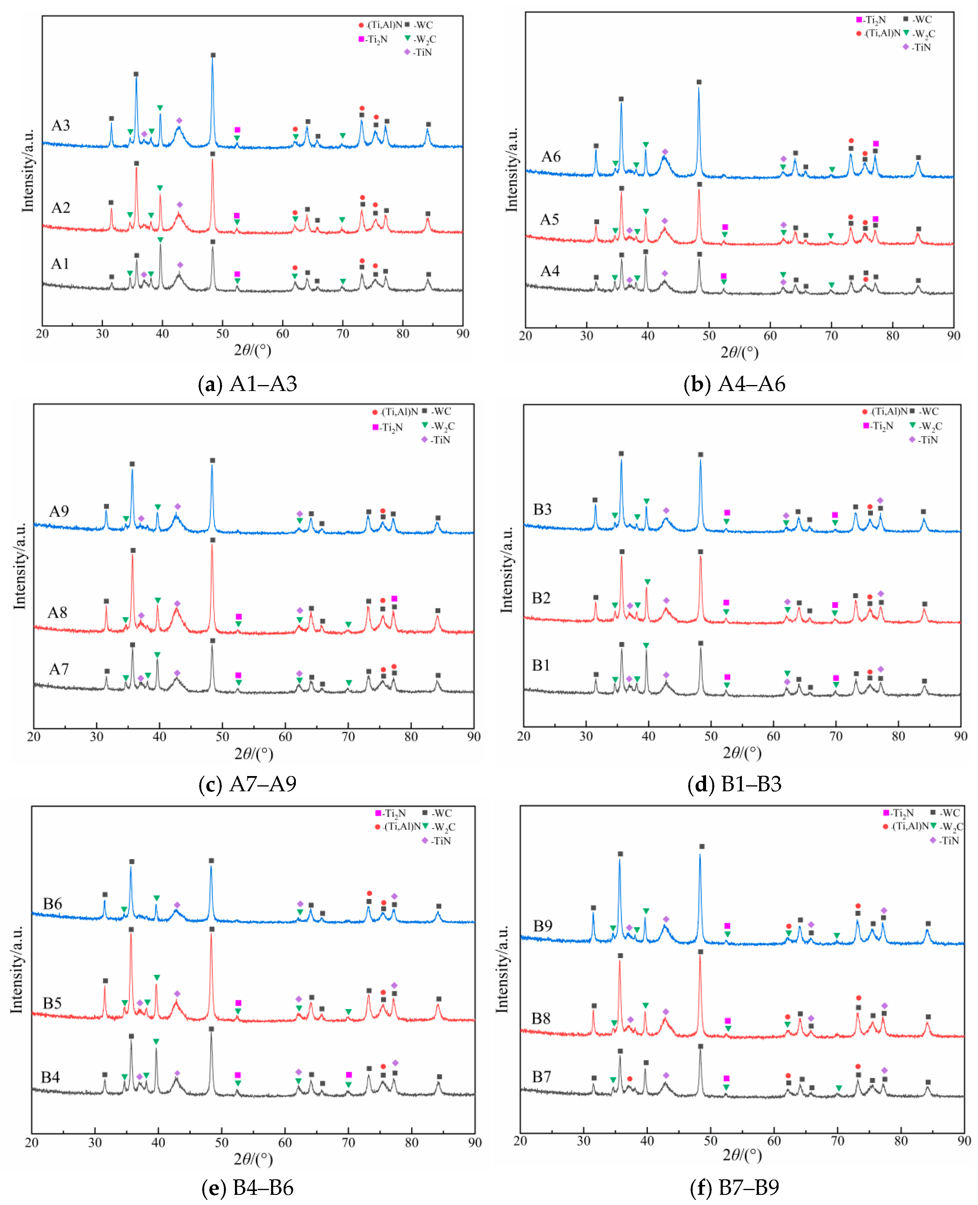
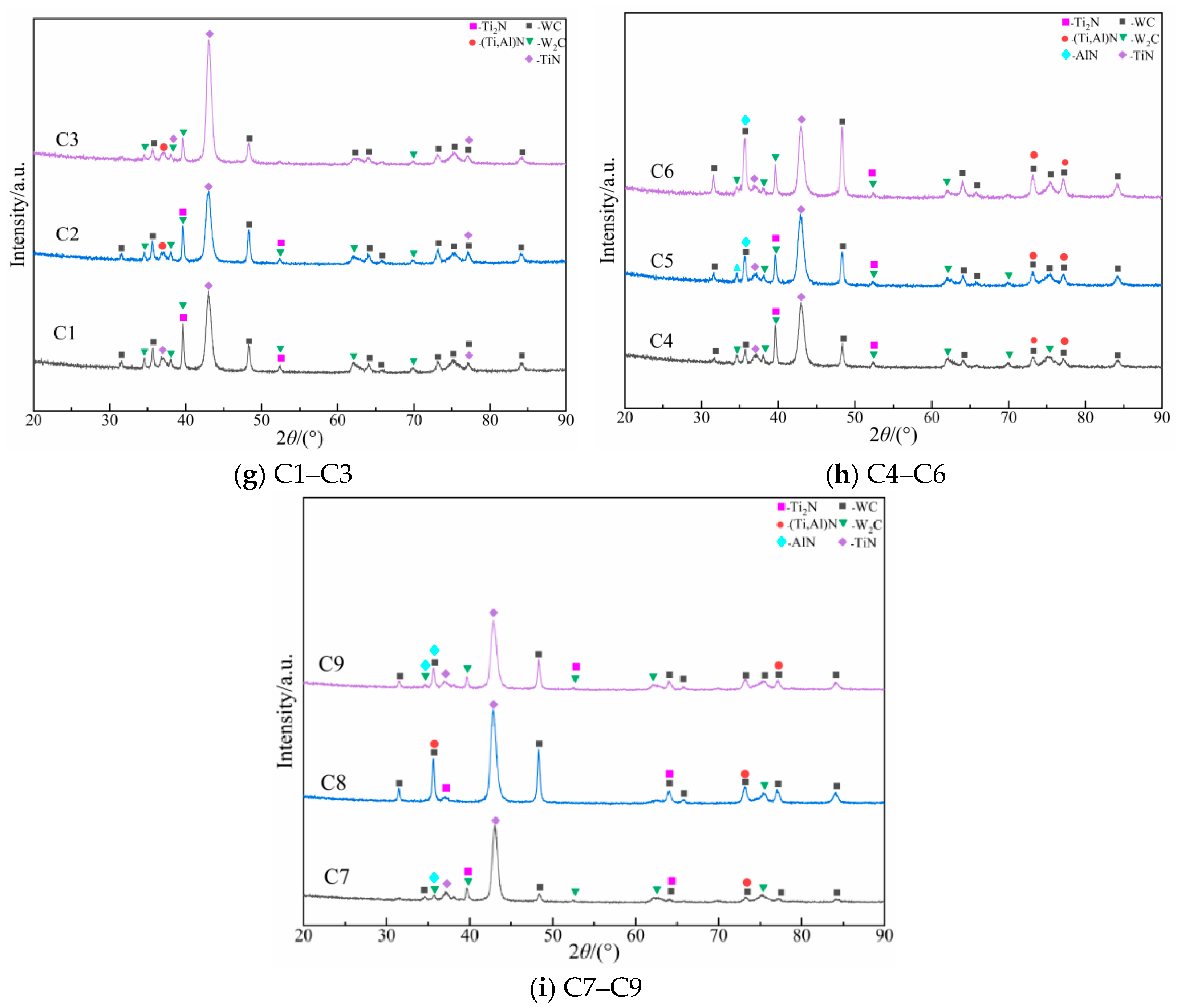
Phase composition analysis was performed on the XRD patterns of the respective specimens using MDI Jade software, and the results are presented in Appendix A Figure A2.
According to the X-ray diffraction (XRD) patterns in Appendix A Figure A2, the phase composition of the cemented carbide substrate primarily consists of WC and W2C. As the predominant phase of the substrate, the WC phase exhibits sharp diffraction peaks with narrow widths, indicating high crystallinity. The W2C phase, acting as a carbon-deficient phase, is formed on the micro-textured substrate surface following laser processing. This phenomenon can be attributed to the rapid temperature rise on the specimen surface during laser irradiation, which facilitates the reaction between carbon elements and oxygen in the air to form CO2 gas. Furthermore, the accelerated diffusion of carbon in the high-temperature molten pool promotes its gaseous escape, leading to localized carbon deficiency upon cooling and re-solidification. The synergistic effect of both processes triggers the formation of the W2C phase on the specimen surface. The W2C phase possesses a close-packed hexagonal (CPH) lattice, identical to the hexagonal structure of WC, and is characterized by high hardness and excellent wear resistance. However, the fracture toughness of the W2C phase is significantly lower than that of the WC phase [32].
The XRD patterns in Appendix A Figure A2 indicate that the primary phases within the coatings of the textured TiSiN/TiAlSiN/TiAlN composite coated (Group A), textured TiSiN/TiAlN composite coated (Group B), and textured TiAlSiN coated (Group C) specimens consist of TiN and (Ti,Al)N phases. Since Ti is the metallic element with the highest concentration during the coating deposition process, it reacts more readily with N from the nitrogen gas to form TiN compounds. Consequently, the TiN phase serves as the dominant phase component of the TiN-based coatings. Additionally, a small amount of the Ti2N phase is detected in all three groups of coated specimens, which is primarily attributed to the high Ti content present during the deposition process.
Al elements from the target material predominantly exist as (Ti,Al)N solid solution phases in the three coatings. The diffraction peaks of the (Ti,Al)N solid solution are positioned between those of TiN and AlN, shifting toward higher diffraction angles (2). This shift is caused by the substitution of Ti atoms by Al atoms, which have a smaller atomic radius, thereby reducing the lattice constant of the TiN crystal. Furthermore, a minor AlN phase is observed in some Group C specimens, which is attributed to the higher Al content in the TiAlSiN coating, leading to the combination of Al and N atoms into AlN compounds. The introduction of Si also restricts the growth of (Ti,Al)N solid solutions and TiN crystals, altering the elemental diffusion paths and causing Al enrichment at the grain boundaries, which further promotes AlN formation.
The Si element primarily exists in the form of the amorphous Si3N4 phase within TiN-based coatings. Since X-ray diffraction (XRD) tests only detect the diffraction effects between crystalline structures, the amorphous Si3N4 phase cannot be directly identified in the XRD patterns. However, in the XRD patterns of the TiSiN/TiAlSiN/TiAlN multilayer coated specimens (Group A) and the TiSiN/TiAlN composite coated specimens (Group B), the TiN diffraction peaks within the 2 range of 40° to 50° exhibit a tendency toward a “broad hump” characteristic, accompanied by significant peak broadening [33]. This feature indirectly indicates the presence of amorphous structures and refined grains within the TiN diffraction peaks at these angles. Consequently, it can be inferred that the TiSiN/TiAlSiN/TiAlN (Group A) and TiSiN/TiAlN (Group B) composite coated specimens contain the amorphous Si3N4 phase.
The surfaces of Group A and B specimens consist of TiSiN with a relatively high Si-to-other-element ratio, resulting in a structure where TiN grains are encapsulated by amorphous Si3N4. In contrast, the Si ratio in Group C is lower, making the “broad hump” and broadening effects less pronounced. Figure 13 illustrates the phase grain structure of the textured TiN-based coated cemented carbide specimens.
Figure 13.
Schematic of the phase grain structures of the textured TiN-based coated cemented carbide specimens.
4.2. Effects of Different Micro-Texture Parameters and Coating Types on Surface Phase Grain Size
Based on the XRD patterns of the textured TiN-based coated specimens, the grain size of each specimen was calculated using the Scherrer equation, as expressed by Equation (5). Regarding the grain size of the coating phases, the calculation was performed on the primary diffraction peaks representing their main phase compositions. For the grain size of the substrate phases, the values for the primary phases were calculated and subsequently averaged. The grain sizes of the coating and substrate phases were recorded as the experimental results, which are presented in Figure 14 and Figure 15.
where k is the Scherrer constant, taken as 0.89; is the X-ray wavelength; represents the full-width at half-maximum (FWHM) of the diffraction peak; and denotes the diffraction angle.
Figure 14.
Grain size of the coating phases of the textured TiN-based coated specimens.
Figure 15.
Average grain size of the textured TiN-based coated specimens. (a) Average grain size of the Group A substrate. (b) Average grain size of the Group B substrate. (c) Average grain size of the Group C substrate.
Based on the results presented in Figure 14, it can be observed that when the type of TiN-based coating on the specimen surface varies, the grain sizes of the coating phases in the textured TiSiN/TiAlSiN/TiAlN composite coated (Group A) and textured TiSiN/TiAlN composite coated (Group B) specimens are significantly smaller than those of the textured TiAlSiN coated (Group C) specimen. Related studies have demonstrated [33] that a reduction in grain size can effectively enhance the hardness and toughness of the coating; therefore, a smaller grain size within the coating plays a positive role in improving its physical properties. The primary reason for this phenomenon is that the composite structure composed of multiple compounds can effectively inhibit the columnar crystal growth of TiN-based coatings. Changes in the different compound components within the TiN-based coating lead to crystal growth interruption and renucleation, thereby effectively restricting the grain size of the coating phases. Furthermore, Si3N4 within the outer TiSiN compound forms an amorphous phase at the grain boundaries of the TiN-based coating columnar crystals, which further inhibits their subsequent growth.
Except for the case where the substrate micro-texture diameter is 60 μm, the grain sizes of the coating phases in the textured TiSiN/TiAlSiN/TiAlN composite coated (Group A) specimens are consistently smaller than those in the textured TiSiN/TiAlN composite coated (Group B) specimens. The smaller grain size of the TiSiN/TiAlSiN/TiAlN composite coating is attributable to the greater variation in compound components from the substrate interface to the coating surface. Consequently, the inhibitory effect on coating grain growth is more significant compared to that of the TiSiN/TiAlN composite coating [34].
To investigate the effects of different TiN-based coating types and substrate micro-texture geometric parameters on the coating grain size, a range analysis was performed on the grain size results, as illustrated in Figure 16. According to the range analysis in Figure 15, as the micro-texture diameter increases, the area of the recast layer at the texture edges also expands. This surface recast layer is prone to inducing a “shadowing effect” during the deposition process, which subsequently reduces the number of stable nuclei that can form and grow continuously during the coating deposition at the micro-texture edges. Consequently, larger-sized coating grains are preserved, resulting in a larger measured grain size of the coating phases during X-ray diffraction. Therefore, the micro-texture diameter exerts the most significant influence on the grain size of the textured TiSiN/TiAlSiN/TiAlN composite coated specimens.
Figure 16.
Range analysis results for the grain size of the textured TiN-based coated specimens. (a) Range analysis results for the grain size of the Group A coating phase. (b) Range analysis results for the grain size of the Group B coating phase. (c) Range analysis results for the grain size of the Group C coating phase.
As the micro-texture spacing increases, the area fraction of the micro-textures on the cemented carbide substrate surface decreases accordingly. In this case, the adverse effects of the micro-textures on the TiSiN/TiAlN composite coating are weakened; consequently, smaller coating grains are observed during X-ray diffraction. Therefore, the micro-texture spacing exerts the most significant influence on the grain size of the textured TiSiN/TiAlN composite coated specimens. Furthermore, the Si content in the coating compounds near the substrate side of the TiSiN/TiAlN composite coating is relatively low. As a result, its sensitivity to variations in the micro-texture diameter is lower than that of the TiSiN/TiAlSiN/TiAlN composite coating.
To investigate the effects of substrate micro-texture geometric parameters on the grain size of the substrate, a range analysis was performed on the results shown in Figure 15. The analysis reveals that the micro-texture diameter exerts the most significant influence on the average grain size of the micro-textured cemented carbide substrate. With the laser parameters for micro-texture fabrication held constant, the micro-texture diameter determines the laser energy input for an individual micro-texture. The resulting laser energy input on the cemented carbide surface induces melting and resolidification of the material within the micro-textured regions, a process that leads to variations in the grain size of the substrate phases [35]. As the micro-texture diameter increases from 40 μm to 50 μm, the laser energy input on the cemented carbide surface increases, raising the surface temperature. This leads to the melting and flow of the Co element, which promotes the rearrangement and agglomeration of WC grains, thereby manifesting as an increase in the average grain size of the substrate. However, as the micro-texture diameter further increases from 50 μm to 60 μm, the distribution of Co and WC grains within the substrate becomes more uniform and undergoes further refinement, resulting in a reduction in grain size.
According to the range analysis in Figure 17, the interaction between micro-texture diameter (D) and spacing (L) exerts the most significant influence on the grain size of the coating phase for the Group C TiAlSiN coated specimens. This is because the multiple compound components within the TiSiN/TiAlN and TiSiN/TiAlSiN/TiAlN composite coatings, along with the surface amorphous Si3N4 phase, can effectively restrict crystal growth; consequently, these coatings are less sensitive to variations in the substrate micro-texture geometric parameters. Appendix A Table A2 presents the binary table for the interaction between micro-texture diameter (D) and micro-texture spacing (L) regarding the grain size of the Group C coating phases.
Figure 17.
Range analysis results for the average grain size of the textured TiN-based coated substrate specimens. (a) Range analysis results for the average grain size of Group A substrate specimens. (b) Range analysis results for the average grain size of Group B substrate specimens. (c) Range analysis results for the average grain size of Group C substrate specimens.
When the micro-texture spacing of the TiAlSiN coating substrate is at its maximum while the micro-texture diameter is not at the maximum level, the overall area fraction of the micro-textures remains low, allowing the columnar crystals of the TiAlSiN coating to grow fully on the relatively flat substrate. In contrast, when the micro-texture spacing is at the minimum level and the micro-texture diameter is at the maximum level, the overall area fraction is high; consequently, the number of coating nuclei at the micro-texture edges decreases, and the larger area fraction further amplifies this adverse effect. Therefore, in these two cases, the specimen surfaces exhibit an increase in the grain size of the coating phases. However, for the Group C TiAlSiN coated specimens under other micro-texture parameters, the micro-textured cemented carbide surface provides more starting sites for nucleation and grain growth during the TiAlSiN coating deposition [36], which is conducive to the refinement of the coating grain size.
5. Comparative Analysis of Surface Mechanical Properties of Textured Multicomponent TiN-Based Coated Cemented Carbides
5.1. Effects of Different Micro-Texture Parameters and Coating Types on Surface Microhardness
Microhardness reflects the overall ability of the specimen surface (under the combined effect of the coating and the substrate) to resist plastic deformation. The measured microhardness results for the textured multicomponent TiN-based coated cemented carbide specimens are presented in Figure 18. Additionally, the mechanism of the influence on the surface microhardness of these specimens is illustrated in Figure 19. By comparing the average microhardness values of the textured TiN-based coated cemented carbide specimens with different coating types, it is observed that, compared with the textured TiAlSiN coated specimens, the textured TiSiN/TiAlSiN/TiAlN composite coated and textured TiSiN/TiAlN composite coated specimens exhibit microhardness enhancements of 17.94% and 10.32%, respectively.
Figure 18.
Microhardness results for the textured multicomponent TiN-based coatings. (a) Microhardness results for the Group A textured multicomponent TiN-based coatings. (b) Microhardness results for the Group B textured multicomponent TiN-based coatings. (c) Microhardness results for the Group C textured multicomponent TiN-based coatings.
Figure 19.
Schematic of the influence mechanism on the microhardness of the textured multicomponent TiN-based coated cemented carbide specimens.
The mechanism analysis reveals that with the introduction of multiple chemical components (TiSiN, TiAlSiN, and TiAlN) within the TiN-based composite coating structure, the elastic modulus mismatch existing between the interfaces of different compounds creates dislocation hindrance within the coating. This effectively inhibits the acceleration of plastic deformation under external loading. This inhibitory effect is further strengthened as the number of compound interfaces increases. Combined with the high compactness of the TiSiN surface layer, the surface hardness of the specimens is significantly enhanced.
The range analysis results for the microhardness of the textured TiN-based coated specimens are presented in Figure 20. Regarding the influence of micro-texture geometric parameters on microhardness across different TiN-based coating types, both the textured TiSiN/TiAlSiN/TiAlN composite coated and textured TiSiN/TiAlN composite coated cemented carbide specimens are most significantly affected by variations in the micro-texture spacing. The analysis of the underlying mechanism reveals that when the micro-texture spacing is small, the distribution density of the micro-textures on the substrate surface is high, which maximizes the mechanical interlocking effect at the coating–substrate interface. Simultaneously, the dense laser-fabricated textures lead to a more compact coating structure after deposition, thereby enhancing the overall microhardness of the textured TiN-based coated cemented carbide specimens. Conversely, when the micro-texture spacing is excessively large, the number of micro-textures per unit area decreases substantially, weakening the supportive role of the substrate micro-textures for the coating. This leads to a reduced ability of the overall specimen surface to resist plastic deformation under external loading, consequently resulting in a decrease in the microhardness values.
Figure 20.
Range analysis results for the microhardness of the textured TiN-based coated cemented carbide specimens. (a) Range analysis results for the microhardness of Group A specimens. (b) Range analysis results for the microhardness of Group B specimens. (c) Range analysis results for the microhardness of Group C specimens.
For the textured TiAlSiN coated cemented carbide specimens, variations in the micro-texture diameter exert the most significant influence on the microhardness. When the micro-texture diameter is at its maximum, the area of the recast layer at the micro-texture edges reaches its peak. Due to the intensified coating spallation at the micro-texture edges of the TiAlSiN coating under the maximum diameter condition, the overall ability of the specimen surface to resist deformation caused by external loading is compromised, consequently resulting in the lowest microhardness values.
Compared with the other two types of textured TiN-based composite coated specimens, the internal stress within the surface coating of the textured TiAlSiN coated cemented carbide specimens is more concentrated. Consequently, the overall deformation resistance of the specimen surface is affected by the substrate micro-texture geometric parameters in a more complex manner. Therefore, the interaction between the micro-texture diameter and micro-texture spacing exerts a more significant influence on the microhardness of the textured TiAlSiN coated cemented carbide specimens. Focusing solely on the interaction of the geometric parameters for the Group C specimens, the corresponding binary table is presented in Appendix A Table A3. When the micro-texture spacing is small and the micro-texture diameter is large, the overall area fraction of the micro-textures on the specimen surface is relatively low. Given that the TiAlSiN coating inherently possesses more surface defects, the negative effect on the overall surface hardness of the specimen is exacerbated as the micro-texture diameter increases, thereby resulting in lower microhardness values.
5.2. Effects of Different Micro-Texture Parameters and Coating Types on Surface Nanohardness
Nanohardness represents the resistance of the specimen surface to plastic deformation at the nano-scale. The nanohardness results for each of the textured TiN-based coatings are presented in Figure 21.
Figure 21.
Nanohardness results for the textured multicomponent TiN-based coatings. (a) Nanohardness results for the Group A textured multicomponent TiN-based coatings. (b) Nanohardness results for the Group B textured multicomponent TiN-based coatings. (c) Nanohardness results for the Group C textured multicomponent TiN-based coatings.
Based on the comparison of the average nanohardness values for the textured TiN-based coated cemented carbide specimens with different coating types, the nanohardness of the textured TiSiN/TiAlSiN/TiAlN composite coated specimens is approximately 8% higher than that of the textured TiAlSiN coated specimens. Similarly, the nanohardness of the textured TiSiN/TiAlN composite coated specimens exhibits an enhancement of approximately 7.1% compared to the textured TiAlSiN coated specimens.
The mechanism analysis reveals that the plastic deformation process on the surfaces of the TiSiN/TiAlSiN/TiAlN and TiSiN/TiAlN composite coatings is influenced by the interface effects between different compound components. The elastic modulus mismatch existing among the various compounds (TiSiN, TiAlSiN, and TiAlN) creates a barrier that hinders the movement of dislocations during plastic deformation. Furthermore, the presence of the TiSiN compound contributes to a higher compactness of the coating surface layer, further enhancing the overall performance.
To investigate the effects of substrate micro-texture geometric parameters on the nanohardness of different TiN-based coatings, a range analysis was performed on the nanohardness results of the textured TiN-based coated specimens, as illustrated in Figure 22.
Figure 22.
Range analysis results for the nanohardness of the textured TiN-based coated specimens. (a) Range analysis results for the nanohardness of Group A specimens. (b) Range analysis results for the nanohardness of Group B specimens. (c) Range analysis results for the nanohardness of Group C specimens.
The improved surface compactness of the TiSiN/TiAlSiN/TiAlN and TiSiN/TiAlN composite coatings enhances their load-bearing capacity, thereby increasing the nanohardness. When the micro-texture spacing is moderate, the laser surface treatment results in a more compact deposited coating, while the mechanical interlocking effect at the coating–substrate interface is strengthened [37], leading to higher nanohardness values. However, when the micro-texture spacing is too small, the high area fraction of micro-textures intensifies the influence of the recast layer edges on coating deposition. This increases the occurrence of non-uniform deposition at the micro-texture edges, which reduces the internal compactness of the coating and results in lower nanohardness values. Conversely, when the micro-texture spacing is excessively large, the overall area fraction of the micro-textures on the substrate surface decreases, weakening the mechanical interlocking effect and likewise leading to lower nanohardness. Consequently, the variations in the nanohardness of both composite coatings are primarily influenced by the substrate micro-texture spacing.
The TiAlSiN coating possesses more surface defects compared to the other two TiN-based composite coatings, resulting in poorer surface compactness. Consequently, the nanohardness of the specimens is most significantly influenced by the interaction between the micro-texture diameter and micro-texture spacing, as detailed in the binary table shown in Appendix A Table A4. When both the micro-texture diameter and spacing are at their minimum levels, the lower laser energy used for individual micro-texture fabrication reduces the area of the heat-affected zone (HAZ) on the substrate surface. This is unfavorable for the refinement of coating grains during the growth process, thereby leading to a decrease in the surface nanohardness. Conversely, when both parameters are at their maximum levels, the excessively large micro-texture spacing weakens the positive effects of the substrate micro-textures on the coating. Simultaneously, the larger micro-texture diameter increases the area of the recast layer at the micro-texture edges, where the resulting non-uniform stress distribution in the surrounding regions leads to severe plastic deformation, thus resulting in lower nanohardness values.
5.3. Effects of Different Micro-Texture Parameters and Coating Types on Surface H/E Ratio
Although nanohardness (H) characterizes the resistance of the textured TiN-based coating surface to plastic deformation, it is insufficient to effectively characterize the resistance to contact cracking and localized spallation. Meanwhile, the elastic modulus (E) only reflects the ability of the coating surface to resist elastic deformation; an excessively high elastic modulus can induce the initiation of cracks within the coating. Provided that the nanohardness remains constant, a lower elastic modulus can effectively reduce the stress experienced by the coating surface during the contact process.
The ratio of nanohardness (H) to elastic modulus (E), denoted as the $H/E$ ratio, reflects the elastic strain limit of the coating surface before the onset of plastic deformation. Related studies have demonstrated [38] that this ratio can be utilized to characterize the wear resistance and resistance to spallation of the coating surface. A higher H/E ratio signifies superior wear resistance and resistance to spallation for the textured TiN-based coating surface; therefore, a larger value of this ratio is generally more desirable [39].
Based on the results shown in Figure 23, a comparison of the average H/E ratios for the textured TiN-based coated cemented carbide specimens with different coating types reveals significant enhancements. Specifically, the H/E ratio of the textured TiSiN/TiAlSiN/TiAlN composite coated specimens is approximately 45% higher than that of the textured TiAlSiN coated specimens. Similarly, the H/E ratio of the textured TiSiN/TiAlN composite coated specimens exhibits an increase of approximately 42% compared to the textured TiAlSiN coated specimens.
Figure 23.
H/E ratio results for the textured multicomponent TiN-based coatings. (a) H/E ratio results for the Group A textured multicomponent TiN-based coatings. (b) H/E ratio results for the Group B textured multicomponent TiN-based coatings. (c) H/E ratio results for the Group C textured multicomponent TiN-based coatings.
The mechanism analysis reveals that the nanohardness (H) of the TiSiN/TiAlSiN/TiAlN and TiSiN/TiAlN composite coatings is higher than that of the TiAlSiN coating. Within the TiSiN surface layer of these two TiN-based composite coatings, the amorphous phase structure composed of Si3N4 and the abundance of coating grain boundaries both contribute to an enhanced elastic recovery capability of the coating surface following deformation. Furthermore, the varying compound components from the substrate side to the coating surface in these two composite coatings effectively dissipate the impact energy from external loading. This, in turn, increases the elastic strain limit before the onset of plastic deformation.
To investigate the effects of substrate micro-texture geometric parameters on the H/E ratio of different TiN-based coatings, a range analysis was performed on the H/E ratios of the textured TiN-based coated specimens, as illustrated in Figure 24. Furthermore, the influence mechanism on the H/E ratio of the textured TiN-based coated cemented carbide specimens is schematically shown in Figure 25.
Figure 24.
Range analysis results for the H/E ratio of the textured TiN-based coated specimens. (a) Range analysis results for the H/E ratio of Group A specimens. (b) Range analysis results for the H/E ratio of Group B specimens. (c) Range analysis results for the H/E ratio of Group C specimens.
Figure 25.
Schematic of the influence mechanism on the H/E ratio of the textured TiN-based coated cemented carbide specimens.
Substrate micro-textures can disperse the surface stress of the coating and provide a larger adhesion area, thereby creating an interlocking effect with the coating. As the substrate micro-texture diameter of the TiSiN/TiAlSiN/TiAlN composite coating increases, the interlocking effect between the micro-textures and the coating is strengthened. This allows the coating to withstand greater loads before the onset of plastic deformation, thus resulting in an increase in the H/E ratio. Consequently, the micro-texture diameter exerts the most significant influence on the H/E ratio of the textured TiSiN/TiAlSiN/TiAlN composite coated specimens. For the TiSiN/TiAlN composite coating, an excessively large micro-texture spacing weakens the overall interlocking effect of the substrate micro-textures, leading to a reduction in the elastic strain limit. Conversely, when the micro-texture spacing is too small, the excessive texture density increases the overall inhomogeneity of the coating deposition on the substrate surface, which likewise reduces the elastic strain limit. Therefore, the textured TiSiN/TiAlN composite coated specimens are most significantly affected by the micro-texture spacing [37].
Compared with the two TiN-based composite coatings, the TiAlSiN coating exhibits larger grain size, poorer compactness, and higher internal residual stress. Consequently, its H/E ratio is more significantly influenced by the interaction between the micro-texture geometric parameters. The binary table for the interaction of micro-texture diameter and spacing regarding the H/E ratio of the textured TiAlSiN coated specimens is presented in Appendix A Table A5. Under the condition where the micro-texture diameter is at its maximum while the spacing is at its minimum (diameter of 60 μm and spacing of 130 μm), the TiAlSiN coating at the micro-texture edges possesses more defects. The dense micro-texture arrangement increases the overall surface defects, which makes the coating surface more susceptible to plastic deformation, thereby resulting in a lower elastic strain limit. Conversely, when both the micro-texture diameter and spacing are at their minimum levels (diameter of 40 μm and spacing of 130 μm), the effective contact area between individual micro-textures and the coating decreases, weakening the anchoring effect. Simultaneously, the dense micro-texture distribution is unfavorable for the elastic recovery of the coating surface; thus, the surface is most prone to plastic deformation, leading to the lowest elastic strain limit.
6. Conclusions
- (1)
- The composite coating structure significantly enhances the topographical integrity of the textured surfaces. Compared to the single-layer TiAlSiN coating, the TiSiN/TiAlSiN/TiAlN and TiSiN/TiAlN composite coatings effectively buffer the internal residual stress through the gradient transition of multiple compound components. This structural design overcomes the limitation of the TiAlSiN coating being excessively sensitive to substrate micro-irregularities, substantially reducing the spallation density at the recast layer edges of the micro-textures and the defect area fraction on the surface.
- (2)
- The interaction between the amorphous wrapping structure and the micro-textures achieves significant grain refinement. In the composite coatings, the amorphous Si3N4 phase formed by the Si element encapsulates the TiN grains, effectively restricting the growth of columnar crystals. Consequently, the grain sizes of the Group A (TiSiN/TiAlSiN/TiAlN) and Group B (TiSiN/TiAlN) composite coatings are notably smaller than those of the Group C (TiAlSiN coating). Furthermore, due to the shadowing effect of the surface recast layer, the micro-texture diameter exerts the most significant influence on the grain size of the TiSiN/TiAlSiN/TiAlN coatings.
- (3)
- The synergy between micro-textures and multilayer interfaces significantly enhances the overall mechanical properties of the surface. The elastic modulus mismatch among the multilayer compounds (TiSiN, TiAlSiN, and TiAlN) creates effective dislocation hindrance within the coating, which, combined with the high compactness of the TiSiN surface layer, substantially improves the resistance to plastic deformation. Compared to the textured TiAlSiN coated cemented carbide specimens, the textured TiSiN/TiAlSiN/TiAlN and textured TiSiN/TiAlN composite coated specimens exhibit increases in microhardness of 17.94% and 10.32%, respectively. Their nanohardness values are enhanced by approximately 8% and 7.1%, while their H/E ratios improve by approximately 45% and 42%, respectively. Furthermore, the influence mechanisms of the substrate micro-texture geometric parameters on the mechanical properties (microhardness, nanohardness, and H/E ratio) of the various TiN-based coatings have been successfully elucidated.
- (4)
- The substrate micro-texture geometric parameters directly modulate the mechanical interlocking effect at the coating–substrate interface. Rationally designed micro-textures can effectively disperse the loading stress on the coating surface and exert a significant interlocking effect with the coating. The research demonstrates that moderate micro-texture spacing and diameter can maximize the load-bearing capacity of the composite coatings. This enables the TiSiN/TiAlSiN/TiAlN composite coating to maintain excellent resistance to spallation and wear resistance even under complex stress states, making it an ideal composite structure for improving the tribological performance of cemented carbide cutting tools.
Author Contributions
X.T.: Writing—review and editing, Supervision, Project administration, Funding acquisition. X.C.: Writing—review and editing, Writing—original draft, Validation, Supervision, Investigation. S.Y.: Supervision, Project administration, Funding acquisition. D.Y.: Supervision. All authors have read and agreed to the published version of the manuscript.
Funding
This study was funded by the National Natural Science Foundation of China (Project No. 52475445), the Natural Science Foundation of Heilongjiang Province (Project No. LH2024E083) and the Open Project Program of Key Laboratory for Cross-Scale Micro and Nano Manufacturing, Ministry of Education, Changchun University of Science and Technology (CMNM-KF202407).
Institutional Review Board Statement
Not applicable.
Informed Consent Statement
Not applicable.
Data Availability Statement
Data are contained within the article.
Conflicts of Interest
The authors declare that they have no known competing financial interests or personal relationships that could have appeared to influence the work reported in this paper.
Appendix A
Table A1.
Orthogonal experimental design array for each group of textured TiN-based coated cemented carbide specimens.
Table A2.
Binary table for the interaction between micro-texture diameter (D) and spacing (L) regarding the grain size of Group C coatings.
Table A3.
Binary table for the interaction between micro-texture diameter (D) and spacing (L) regarding the microhardness of the textured TiSiAlN coated specimens.
Table A4.
Binary table for the interaction between micro-texture diameter (D) and spacing (L) regarding the nanohardness of the textured TiSiAlN coated specimens.
Table A5.
Binary table for the interaction between micro-texture diameter (D) and spacing (L) regarding the H/E ratio of the textured TiSiAlN coated specimens.
Figure A1.
Quantitative characterization results of the surface morphological quality of the textured multicomponent TiN-based coated cemented carbide specimens.
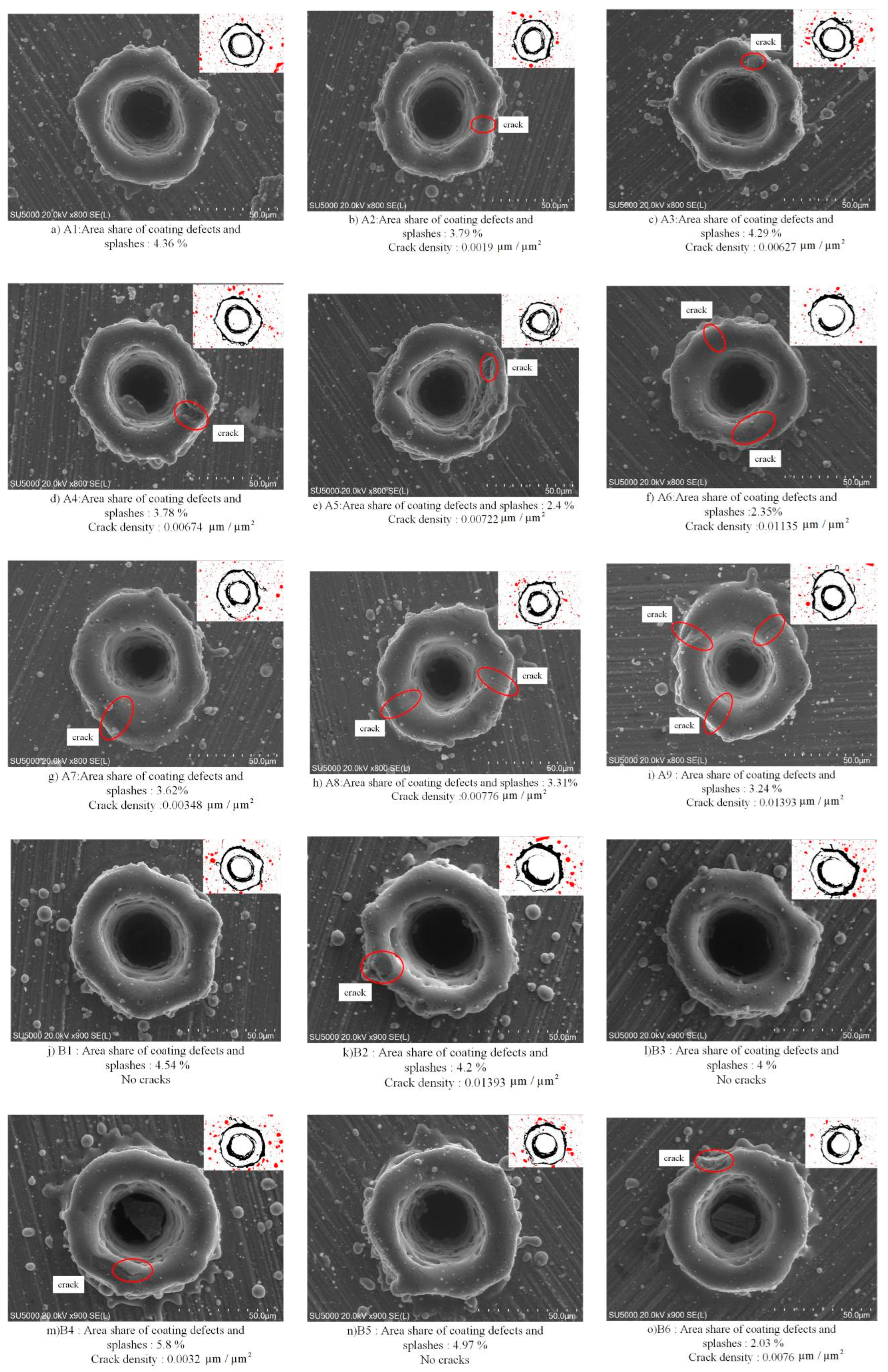
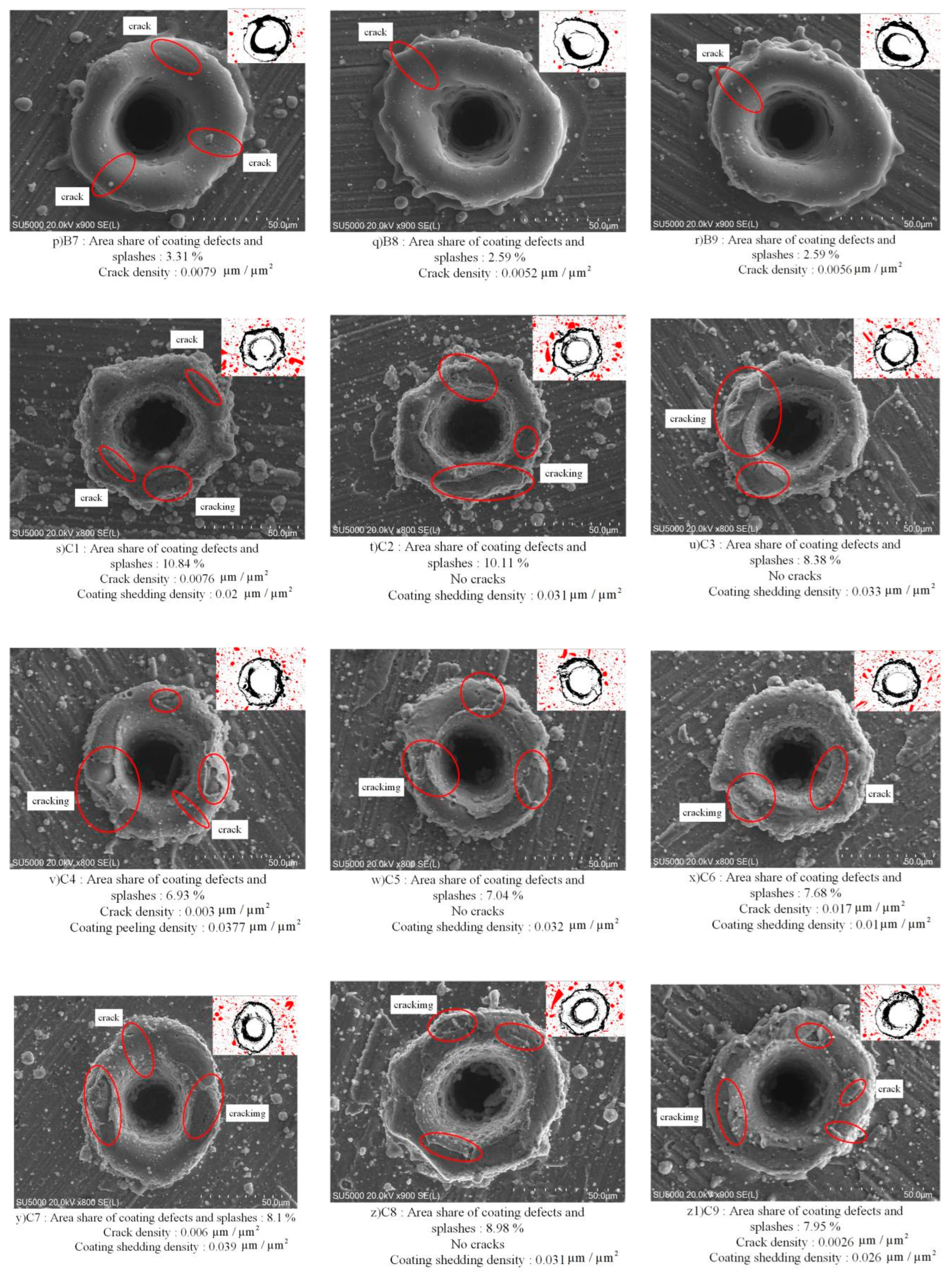
Figure A2.
Phase compositions of the XRD patterns of the textured multicomponent TiN-based coated cemented carbide specimens.
References
- Dai, L.; Zhang, Z.; Zhang, M.; Chen, G.; Mao, C.; Yan, Y.; Duan, Z.; Wang, W. Experimental study on spray assisted laser etching of polycrystalline diamond surface micro-texture. Opt. Laser Technol. 2026, 194, 114528. [Google Scholar] [CrossRef] [Scilit]
- Zhang, P.; Wang, S.; Changyin, L.; Zhang, J.; Sun, Y. Influence of surface micro-textured tools on high-speed machining mechanism of CoCrFeNiAl0.6 high-entropy alloy. J. Braz. Soc. Mech. Sci. Eng. 2025, 47, 382. [Google Scholar] [CrossRef] [Scilit]
- Tong, X.; Wang, B.; Li, X.; Yang, S. Research on prediction method of milling force of micro-textured tools under thermal-assisted conditions. J. Instrum. 2025, 46, 274–287. [Google Scholar]
- Guo, D.; Wang, D.; Wu, S.; Qi, H.; Saetang, V. Investigation on turning of Inconel 718 using differently coated microtextured tools. Proc. Inst. Mech. Eng. 2025, 239, 754–764. [Google Scholar] [CrossRef] [Scilit]
- Tong, X.; Wang, X.; Han, P.; Wang, S. Study on the surface performance strengthening of AlCrN coated cemented carbide by micro-texture laser preparation process. Opt. Laser Technol. 2025, 181, 111819. [Google Scholar] [CrossRef] [Scilit]
- Zhou, Y.; Huang, Q.; Luo, S.; Lin, R. Microstructure and Properties of Al-Cr-N Ternary Wear-Resistant Coatings on Cr12MoV Alloy Tool Steel by Multiarc Ion Plating. Coatings 2025, 15, 487. [Google Scholar] [CrossRef] [Scilit]
- Liu, J.; Mei, H.; Hua, J.; Wang, J.; Wang, Y.; Yi, G.; Deng, X. High-Temperature Oxidation and Wear Resistance of TiAlSiN/AlCrN Multilayer Coatings Prepared by Multi-Arc Ion Plating. Nanomaterials 2025, 15, 503. [Google Scholar] [CrossRef] [Scilit]
- Migranov, S.M.; Kozochkin, P.M.; Gusev, S.A.; Maslov, A.A.; Pristinskii, Y.O. Studies of Innovative Wear-Resistant Coatings for High-Speed Machining. J. Frict. Wear 2026, 46, 227–235. [Google Scholar] [CrossRef] [Scilit]
- Yang, S.; Han, P.; Tong, X.; Liu, X.; Zhang, X. Research on tool mesoscopic geometric feature forming technology and its effect. J. Mech. Eng. 2024, 60, 317–351. [Google Scholar]
- Jiang, Z.; Dong, J.; Kong, F.; Zhou, C. Research status and development of milling technology for titanium alloy. New Technol. New Process 2021, 54–58. [Google Scholar] [CrossRef]
- Sundgren, J.E.; Hentzell, H.T.G. A review of the present state of art in hard coatings grown from the vapor phase. J. Vac. Sci. Technol. A Vac. Surf. Film. 1986, 4, 2259–2279. [Google Scholar] [CrossRef] [Scilit]
- Ran, C. Comparative Study on Cutting Performance of TiN and TiAIN Coated Tools. Master’s Thesis, Southwest University, Chongqing, China, 2013. [Google Scholar]
- Han, W. Study on the Friction and Wear Characteristics of TiN and TiAlN and the Properties of Coated Tools and Gears. Master’s Thesis, Southwest University, Chongqing, China, 2014. [Google Scholar]
- Han, P.; Yang, S.; Ren, Z. Research on micro-texture and coating preparation process strategy for macro and micro properties of cemented carbide surface. Int. J. Refract. Met. Hard Mater. 2026, 135, 107503. [Google Scholar] [CrossRef] [Scilit]
- Shi, X.; Zhang, X.; Kang, X.; Yang, H.; Wu, L. Synergistic effects of laser-textured microgroove geometry and diamond-like carbon coating on tribological performance of SUS304 stainless steel. Surf. Topogr. Metrol. Prop. 2025, 13, 045019. [Google Scholar] [CrossRef] [Scilit]
- Liu, S.; Li, Z.; Su, B.; Wang, H.; Huang, X. Effect of laser processing micro-texture on wear resistance of AlCrN coating on TC4 titanium alloy surface. Met. Heat Treat. 2025, 50, 278–285. [Google Scholar]
- Liu, Y.; Yang, S.; Xiao, Z.; Han, P. Improving Coating Mechanical Properties and Cutting Performance of Carbide Tools Through Combined Technology of Micro-textures and AlCrN Coatings. Metall. Mater. Trans. B 2024, 56, 212–236. [Google Scholar] [CrossRef] [Scilit]
- Guo, Z. Preparation and High Temperature Properties of TiAlSiN Thermal Protective Coating. Master’s Thesis, Shanghai University of Applied Sciences, Shanghai, China, 2023. [Google Scholar]
- Bartosik, M.; Holec, D.; Apel, D.; Klaus, M.; Genzel, C.; Keckes, J.; Arndt, M.; Polcik, P.; Koller, C.; Mayrhofer, P. Thermal expansion of Ti-Al-N and Cr-Al-N coatings. Scr. Mater. 2017, 127, 182–185. [Google Scholar] [CrossRef] [Scilit]
- Wang, H.; Webb, T.; Bitler, W.J. Study of thermal expansion and thermal conductivity of cemented WC–Co composite. Int. J. Refract. Met. Hard Mater. 2015, 49, 170–177. [Google Scholar] [CrossRef] [Scilit]
- Li, X.; Huang, Z.; Du, W.; Liu, S. Study on strength and fatigue life of MK planer with different gouging depths. J. Coal 2012, 37, 162–166. [Google Scholar]
- Du, J.; Tao, G.; Zeng, L.; Chen, H.; Yang, H.; Wu, Z. Research Progress in TiAlSiN Nanocomposite Coatings. Surf. Technol. 2024, 53, 31–54. [Google Scholar]
- Miletić, A.; Panjan, P.; Škorić, B.; Čekada, M.; Dražič, G.; Kovač, J. Microstructure and mechanical properties of nanostructured Ti–Al–Si–N coatings deposited by magnetron sputtering. Surf. Coat. Technol. 2014, 241, 105–111. [Google Scholar] [CrossRef] [Scilit]
- Xu, Y.X.; Chen, L.; Liu, Z.Q.; Pei, F.; Du, Y. Improving thermal stability of TiSiN nanocomposite coatings by multilayered epitaxial growth. Surf. Coat. Technol. 2017, 321, 180–185. [Google Scholar] [CrossRef] [Scilit]
- Xiao, Z. Study on the Effect of Texture size Effect on the Surface Properties and Cutting Performance of Coated Tools. Master’s Thesis, Harbin University of Science and Technology, Harbin, China, 2024. [Google Scholar]
- Tong, X. Precision Distribution Design and Parameter Optimization of Ball-End Milling Cutter Micro-Texture. Doctoral Dissertation, Harbin University of Science and Technology, Harbin, China, 2019. [Google Scholar]
- Tong, X.; Wang, S. Analytical method for surface vibration of textured coated cemented carbide based on STFT. J. Instrum. 2023, 44, 284–295. [Google Scholar]
- Fan, R.; Xie, H.; Xu, J. Research progress of laser processing of gas film hole recast layer. Cast. Technol. 2023, 44, 779–795. [Google Scholar]
- Yang, X.; Fu, Y.; Kuang, X. Numerical Simulation and Experimental Study on Flow Forming of Laser Concave–Convex Microtexture of Cr12 Steel Surface. Met. Mater. Int. 2021, 27, 4225–4234. [Google Scholar] [CrossRef] [Scilit]
- Liang, C.; Jia, Z.; Chen, R. An Automated Particle Size Analysis Method for SEM Images of Powder Coating Particles. Coatings 2023, 13, 1547. [Google Scholar] [CrossRef] [Scilit]
- Maksakova, O.V.; Zhanyssov, S.; Plotnikov, S.V.; Konarski, P.; Budzynski, P.; Pogrebnjak, A.D.; Beresnev, V.M.; Mazilin, B.O.; Makhmudov, N.A.; Kupchishin, A.I.; et al. Microstructure and tribomechanical properties of multilayer TiZrN/TiSiN composite coatings with nanoscale architecture by cathodic-arc evaporation. J. Mater. Sci. 2020, 56, 5067–5081. [Google Scholar] [CrossRef] [Scilit]
- He, W.; Chen, X. Study on microstructure, friction and wear of laser cladding WC/Co coating on high speed steel. Spec. Cast. Non-Ferr. Alloys 2025, 45, 523–528. [Google Scholar]
- Zou, C.; Wang, H.; Li, M.; Yu, Y.; Liu, C.; Guo, L.; Fu, D. Characterization and properties of TiN-containing amorphous Ti–Si–N nanocomposite coatings prepared by arc assisted middle frequency magnetron sputtering. Vacuum 2009, 84, 817–822. [Google Scholar] [CrossRef] [Scilit]
- Yang, S.; Xing, S.; Yu, Y.; Han, P.; Guo, C.; Liu, L. Study on the milling performance of ball-end milling cutter under the combined action of micro-texture of rake and flank face. Ind. Lubr. Tribol. 2023, 75, 510–525. [Google Scholar] [CrossRef] [Scilit]
- Gallero, E.; Outón, J.; Vazquez-Martinez, J.M.; Domínguez, M.; Ledesma, J.; Salguero, J.; Gontard, L.C. Influence of laser parameters on multiscale surface texturing of WC-Co: Formation, characterization and optimization. Opt. Laser Technol. 2025, 192, 113696. [Google Scholar] [CrossRef] [Scilit]
- Sulen, W.L.; Bernard, C.; Onodera, S.; Ishizaki, J.; Mary, N.; Ichikawa, Y.; Ogawa, K. Improvement of the Deposition Efficiency and Adhesion Strength of Cold Sprayed Fluoropolymer Coating by Laser Surface Texturing of the Substrate. Surf. Coat. Technol. 2024, 478, 130489. [Google Scholar] [CrossRef] [Scilit]
- Guo, Z.; Deng, F.; Zhang, L.; Hao, C.; Zhao, X.; Xiang, D. Fabrication and Tribological Properties of Textured Diamond Coatings on WC-Co Cemented Carbide Surfaces. Ceram. Int. 2021, 47, 5423–5431. [Google Scholar] [CrossRef] [Scilit]
- Beake, B.D. The influence of the H/E ratio on wear resistance of coating systems—Insights from small-scale testing. Surf. Coat. Technol. 2022, 442, 128272. [Google Scholar] [CrossRef] [Scilit]
- Leyland, A.; Matthews, A. On the significance of the H/E ratio in wear control: A nanocomposite coating approach to optimised tribological behaviour. Wear 2000, 246, 1–11. [Google Scholar] [CrossRef] [Scilit]
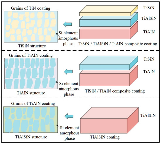
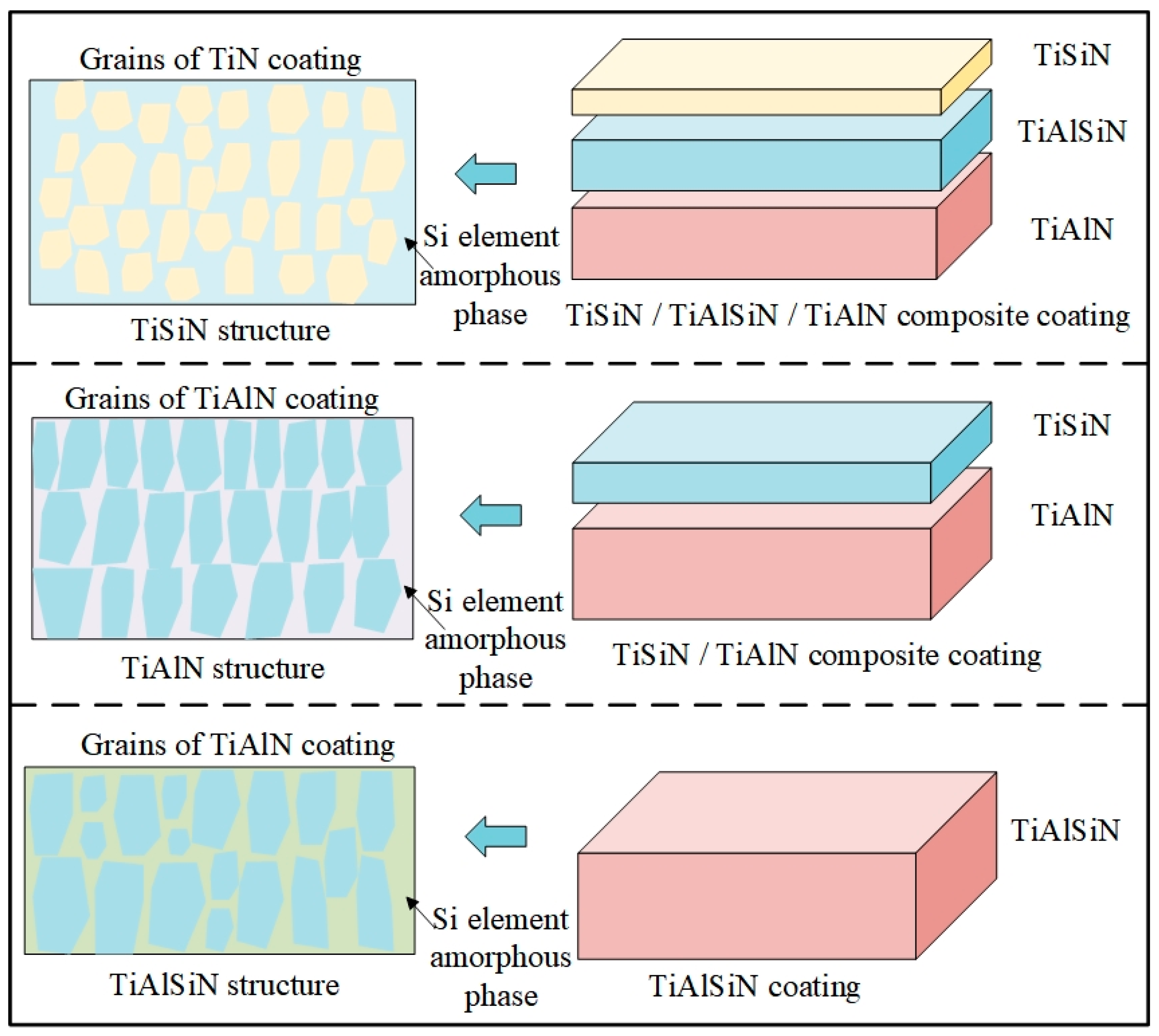
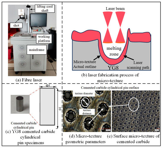
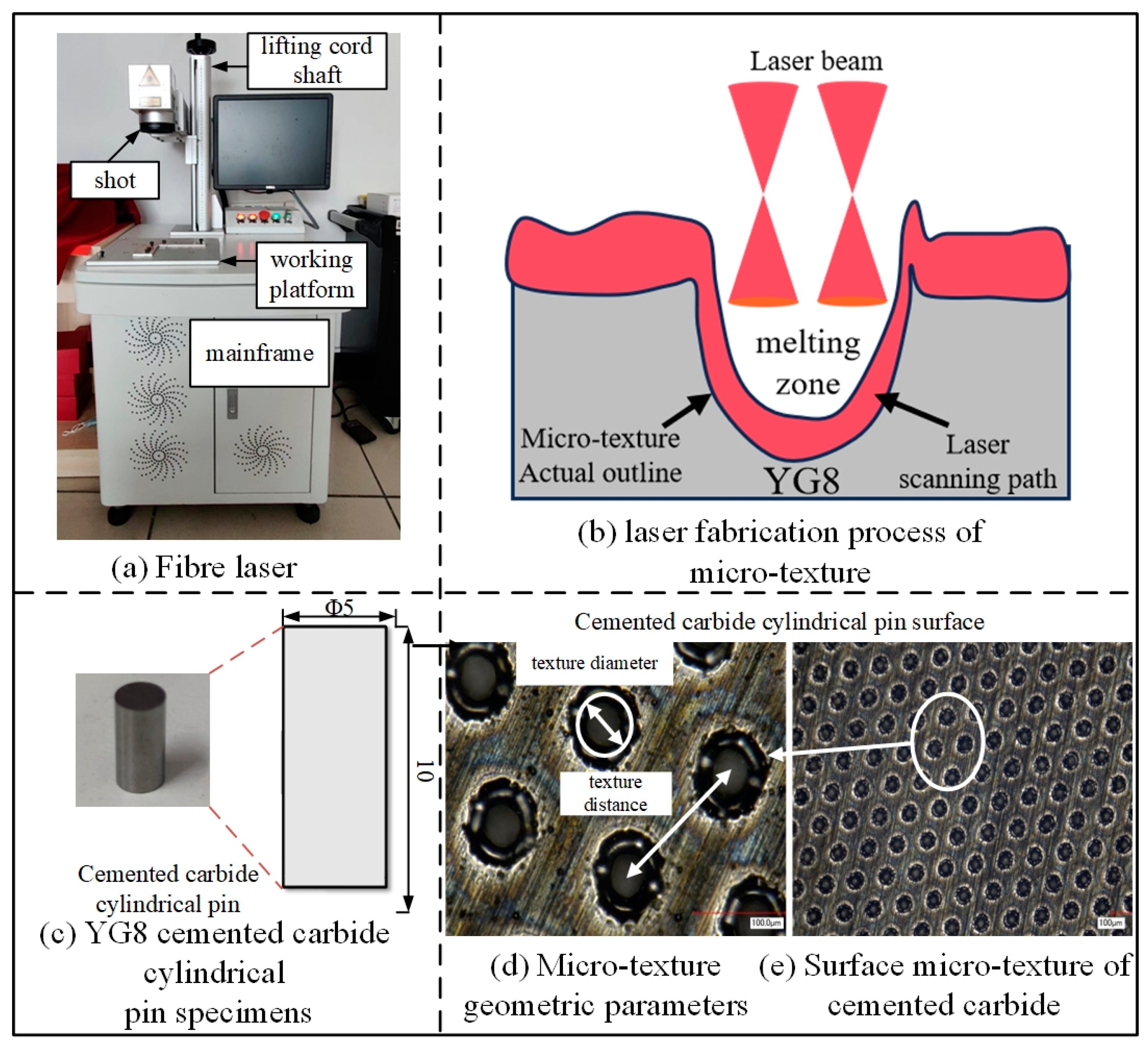
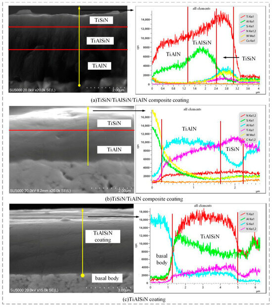
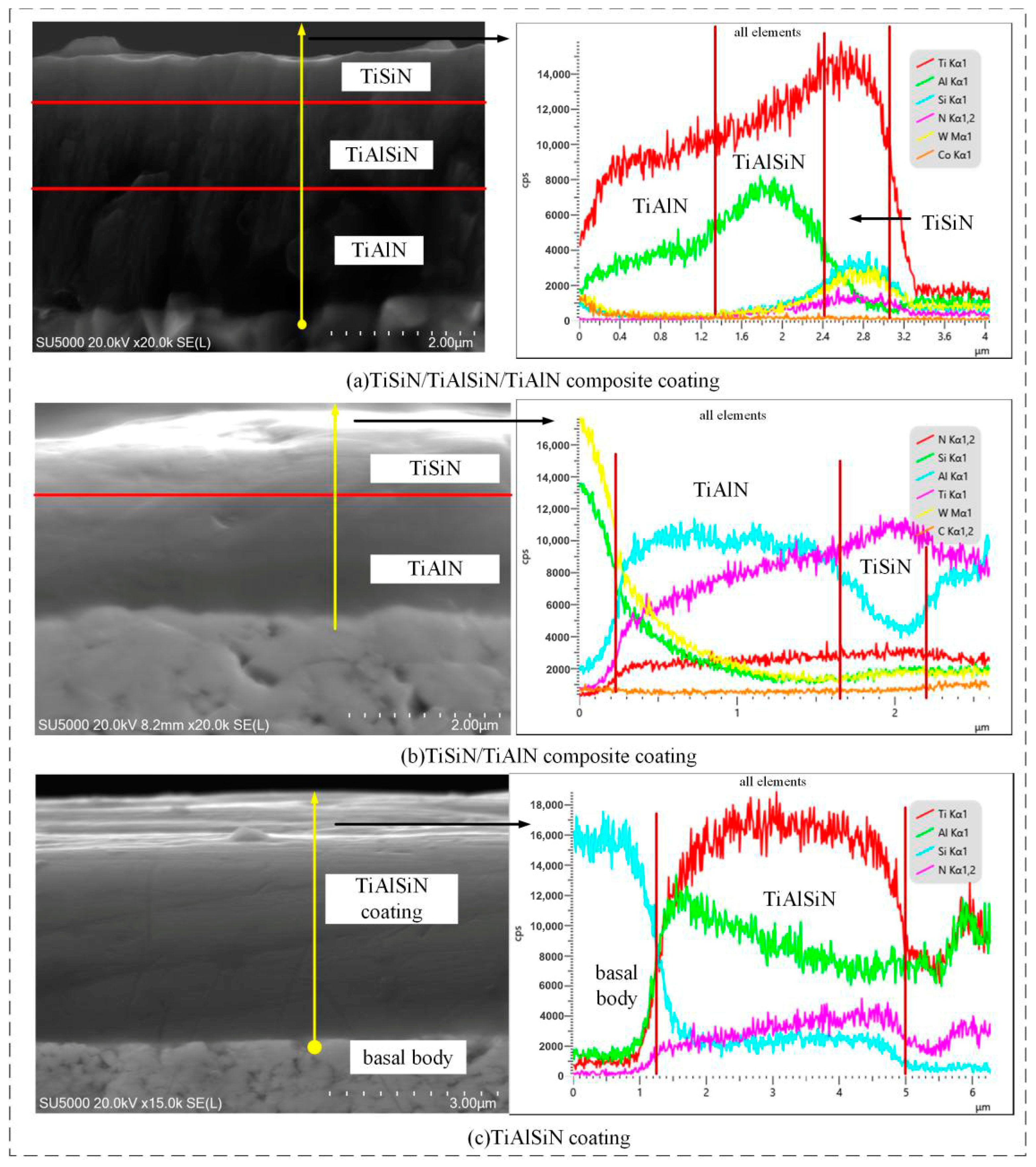
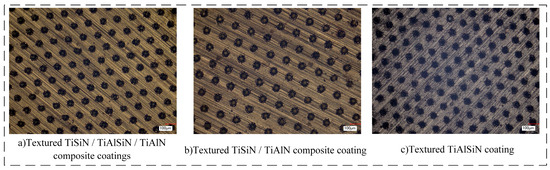
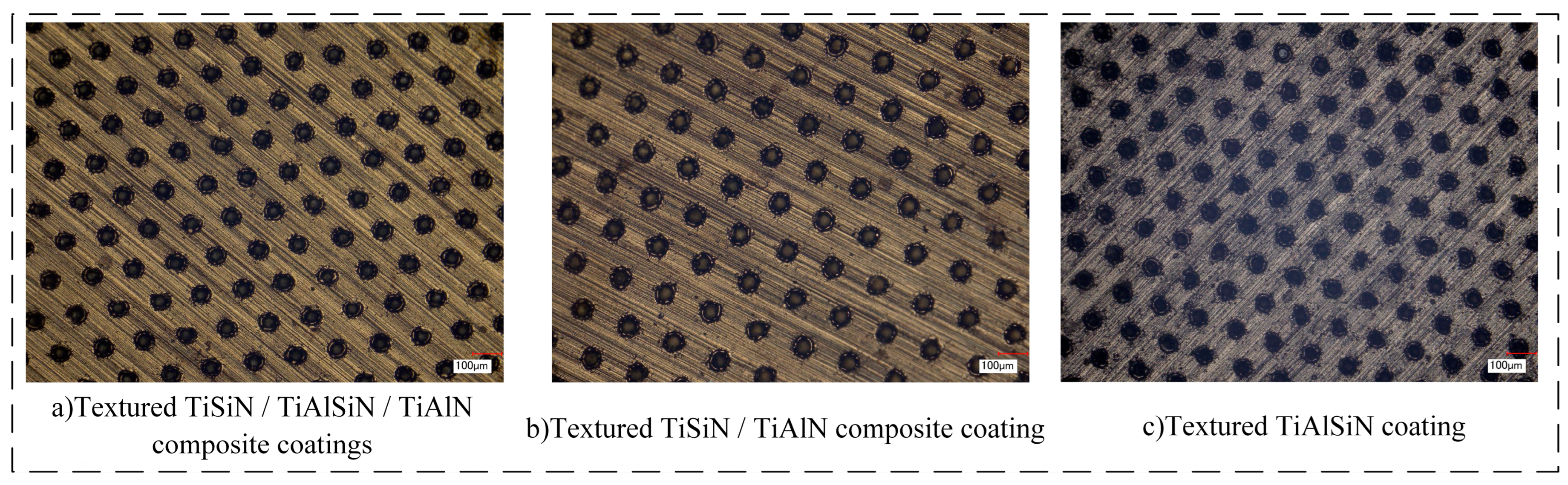
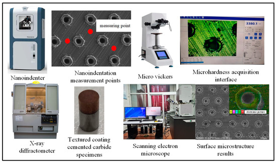
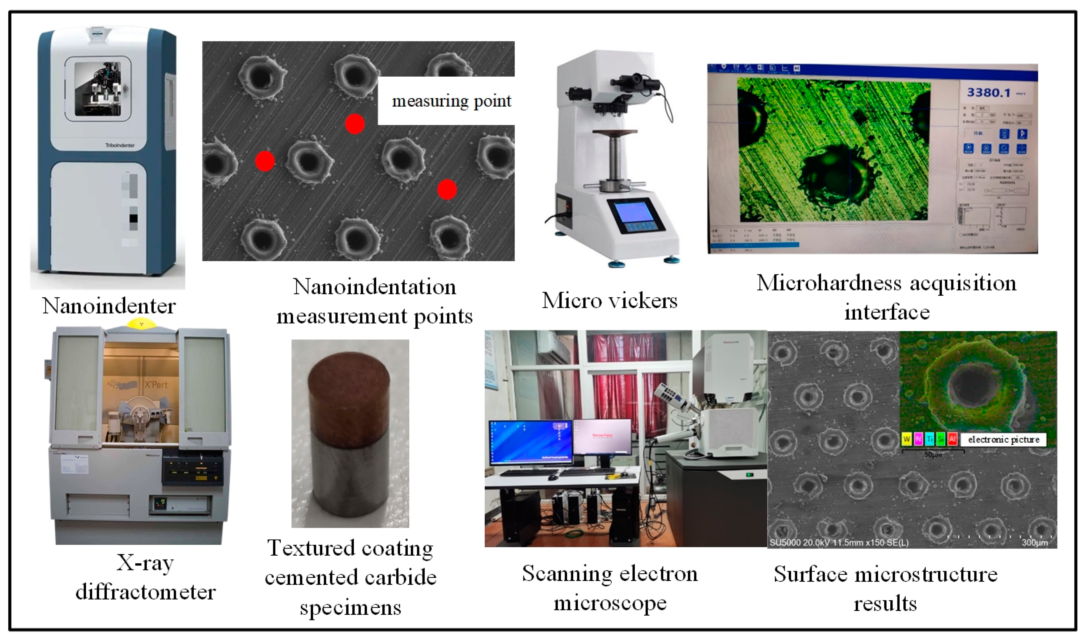
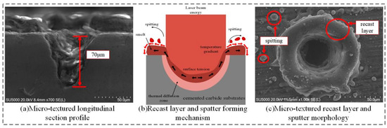
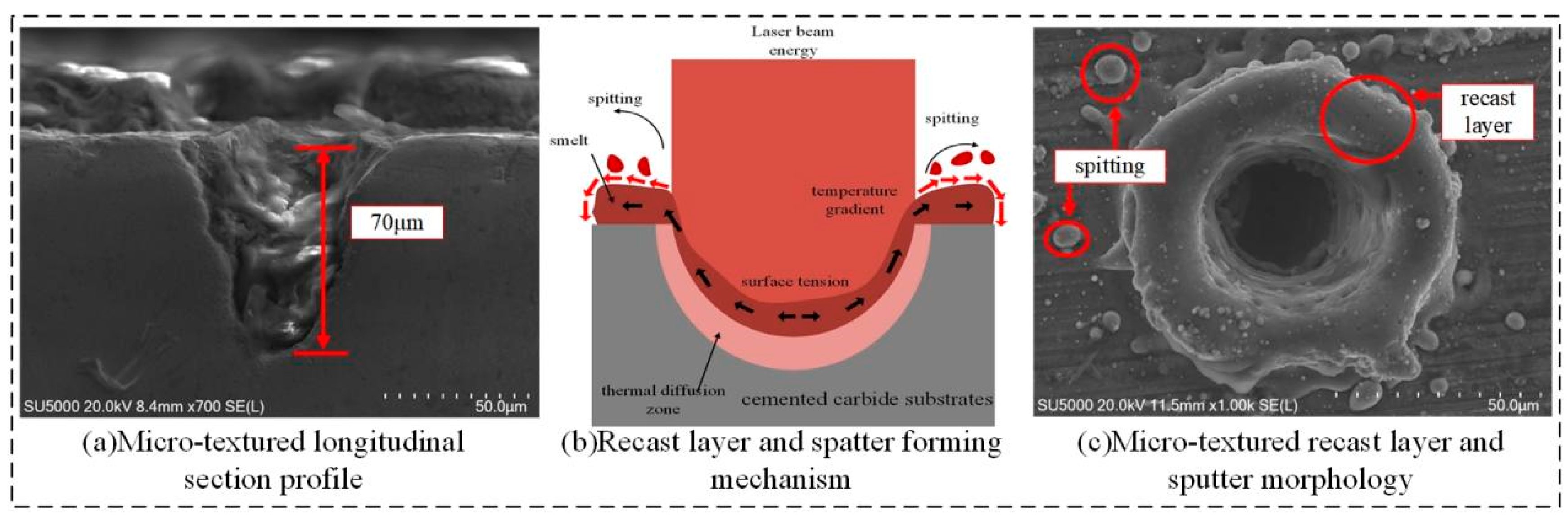
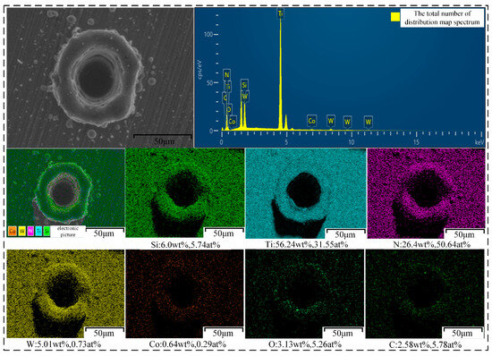
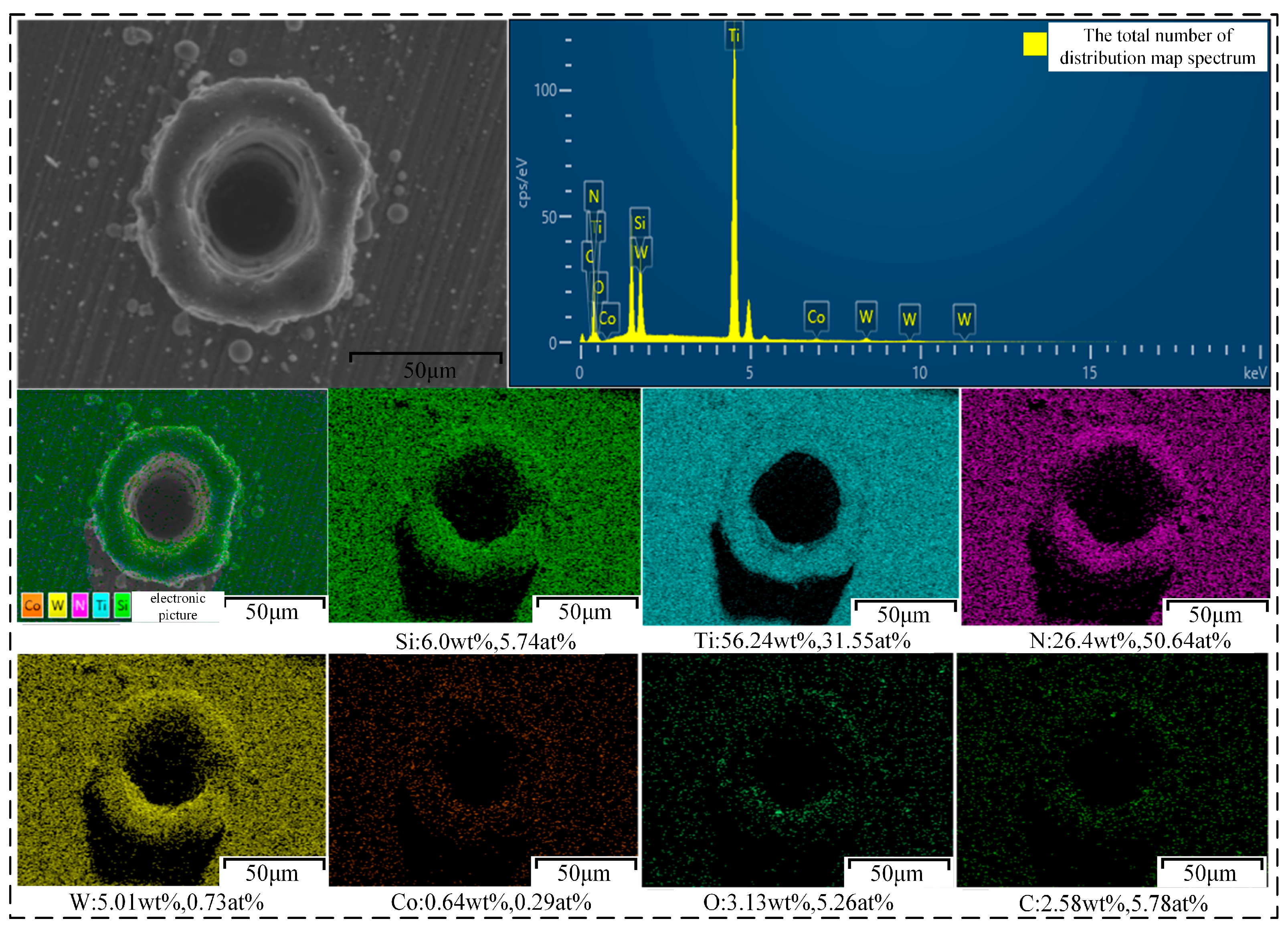
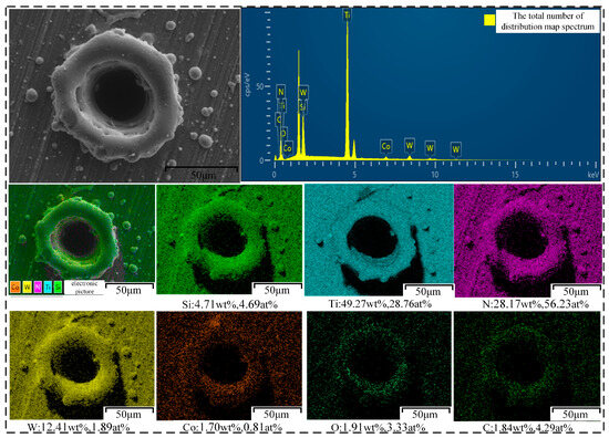
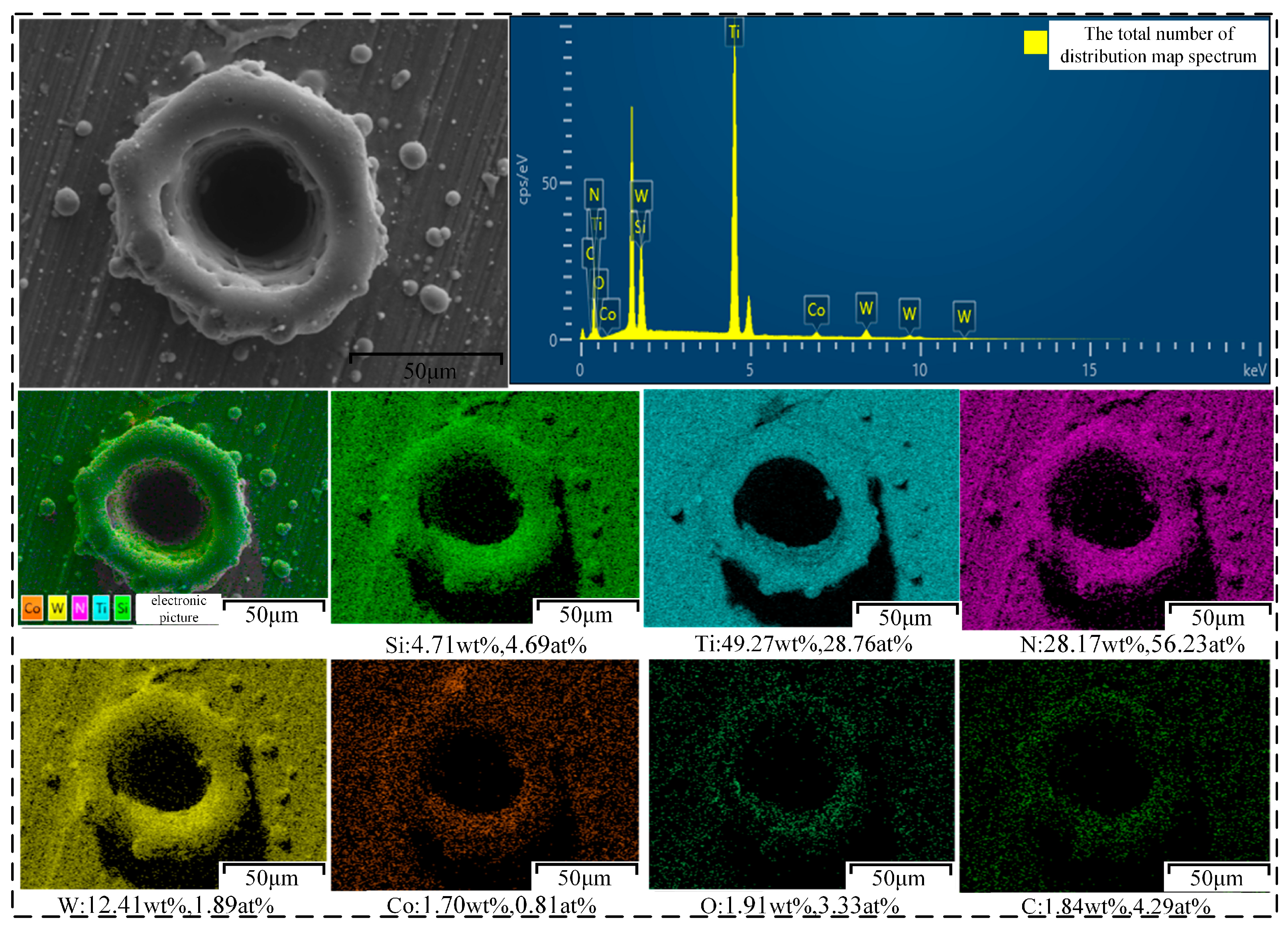
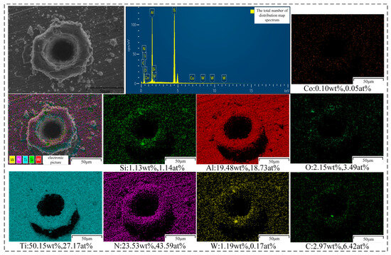
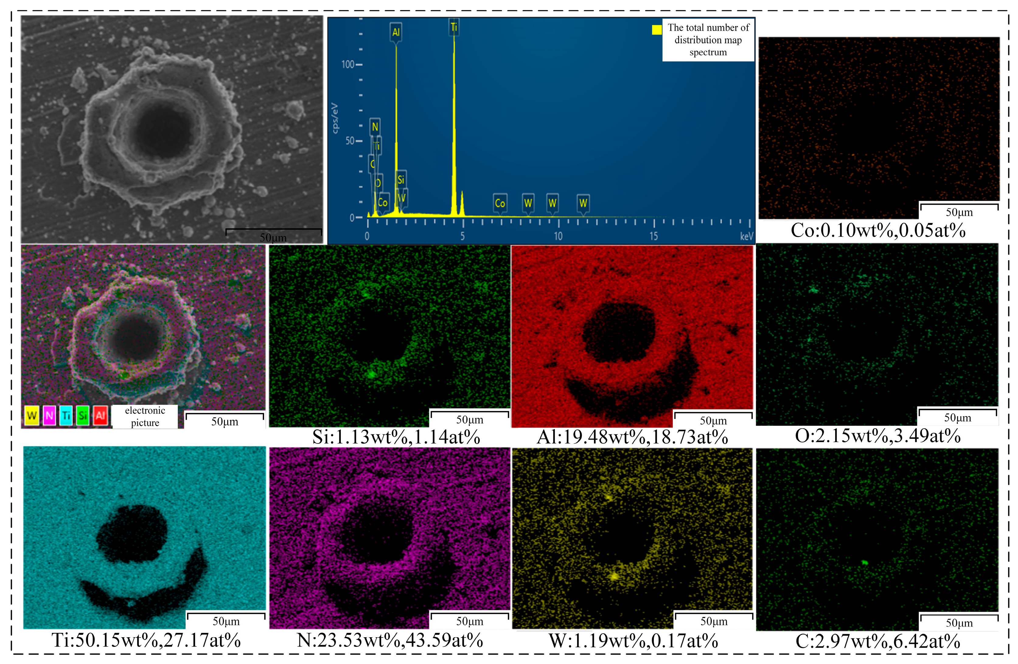
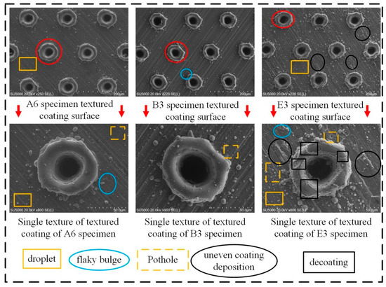
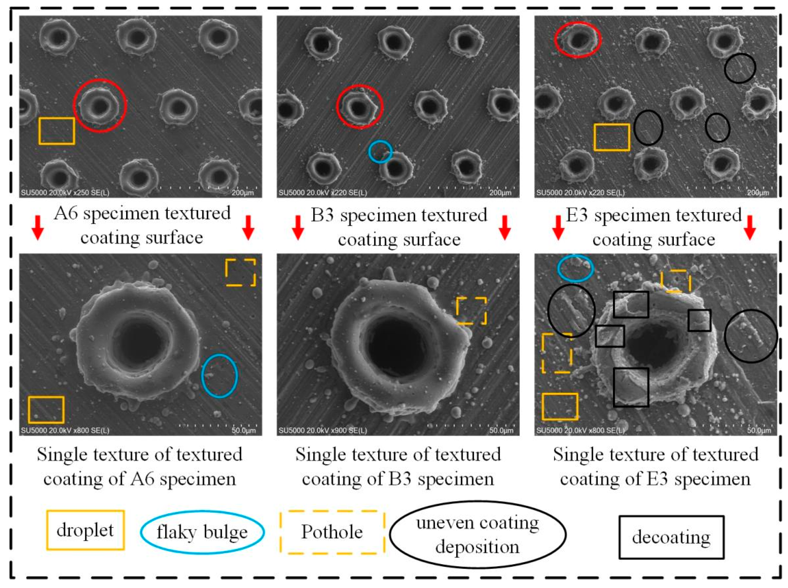
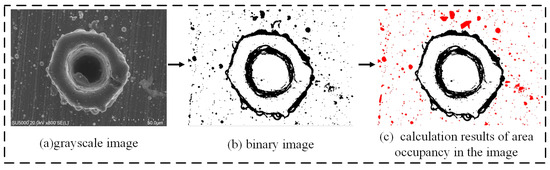
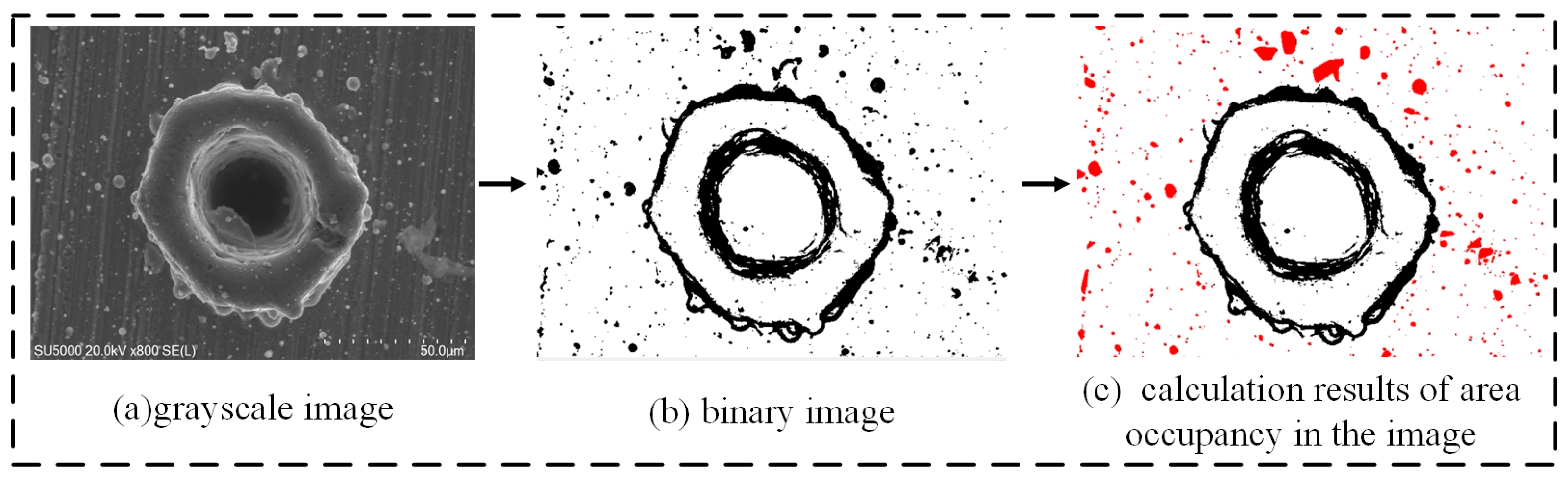
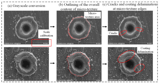
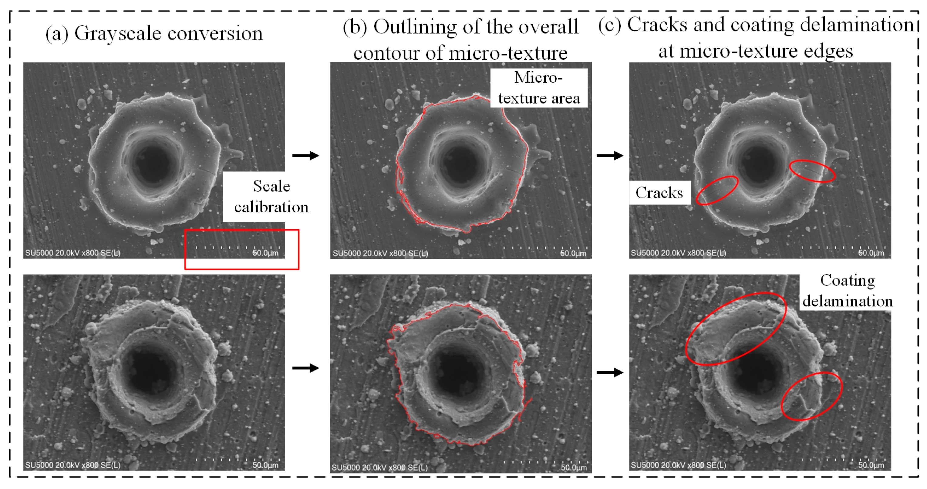
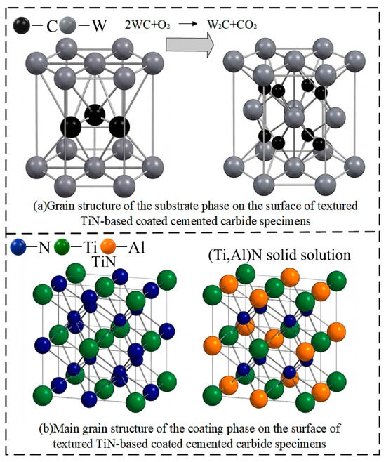
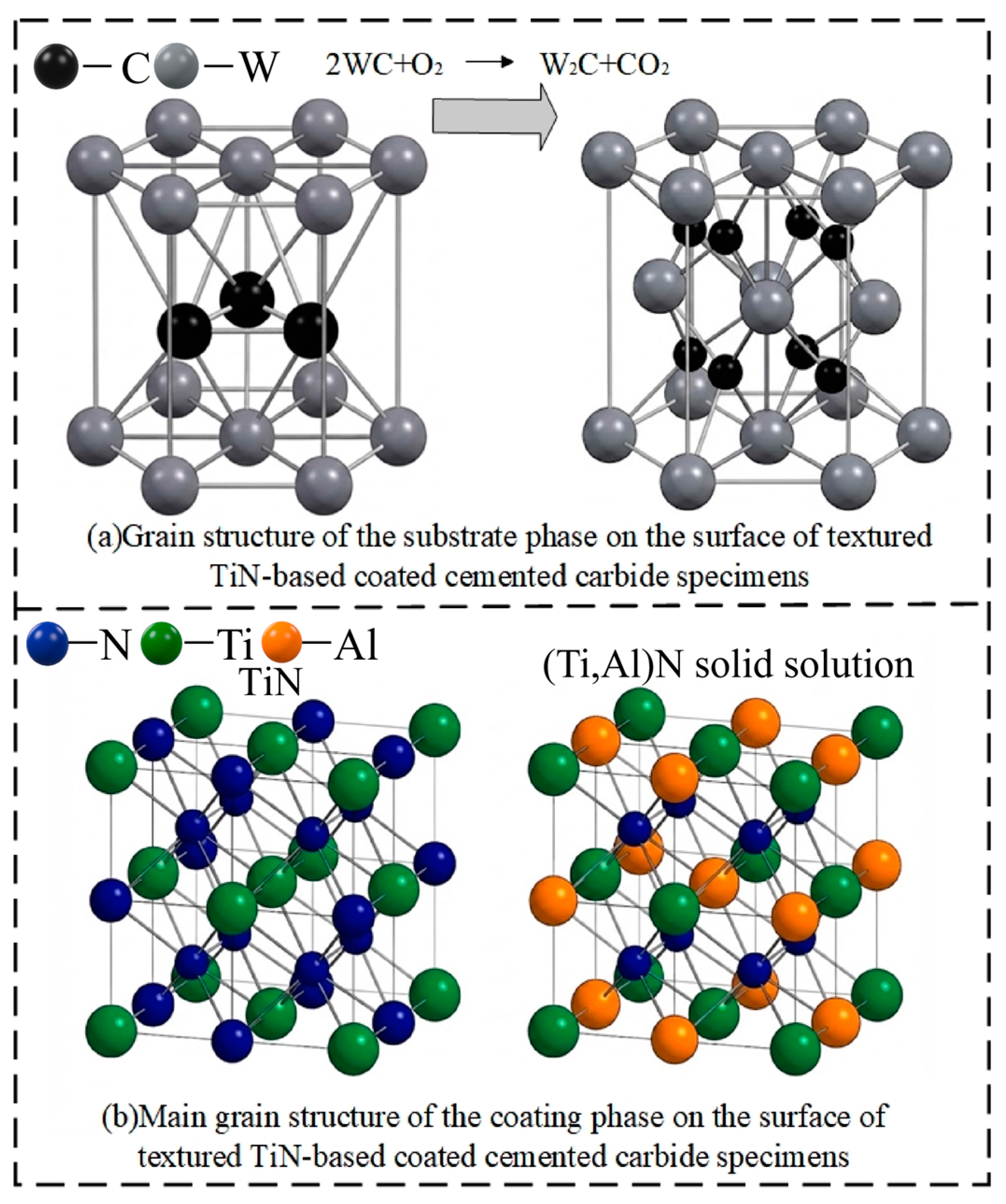
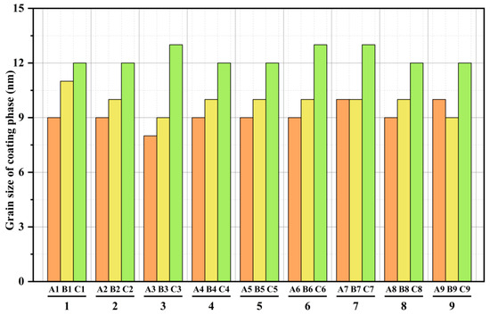
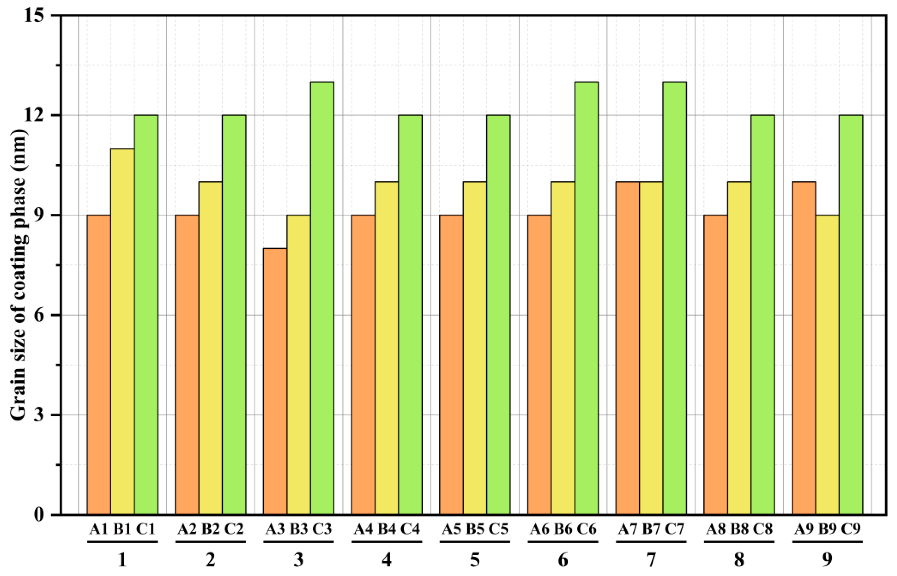
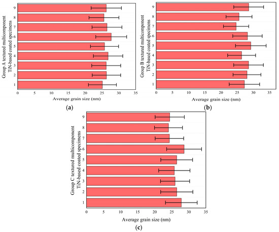
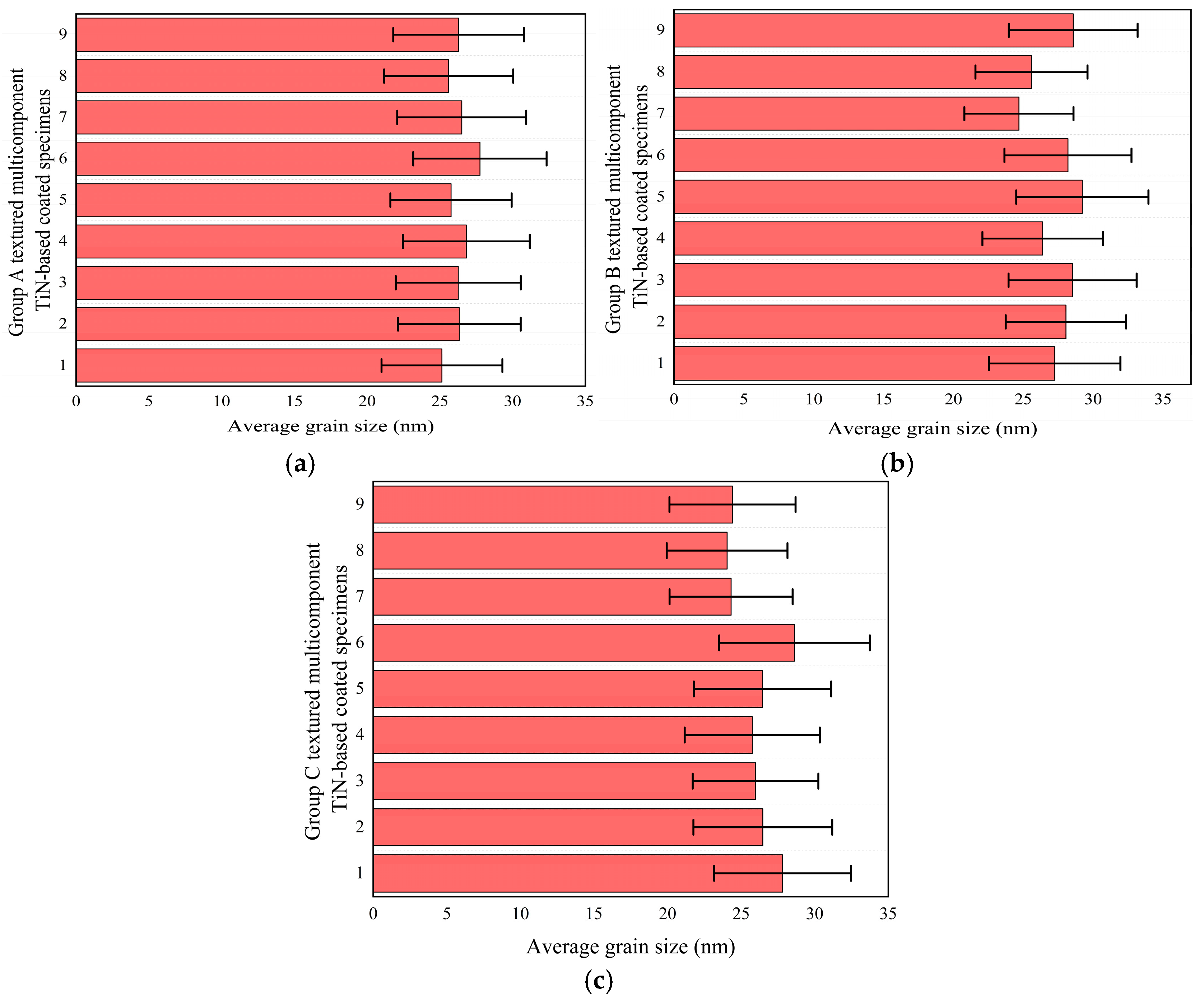
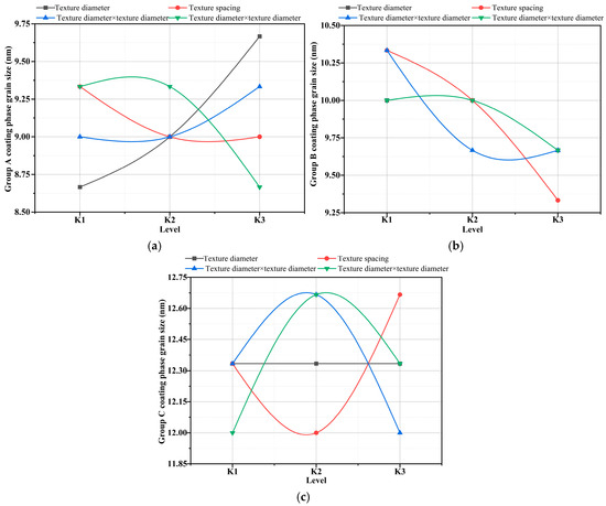
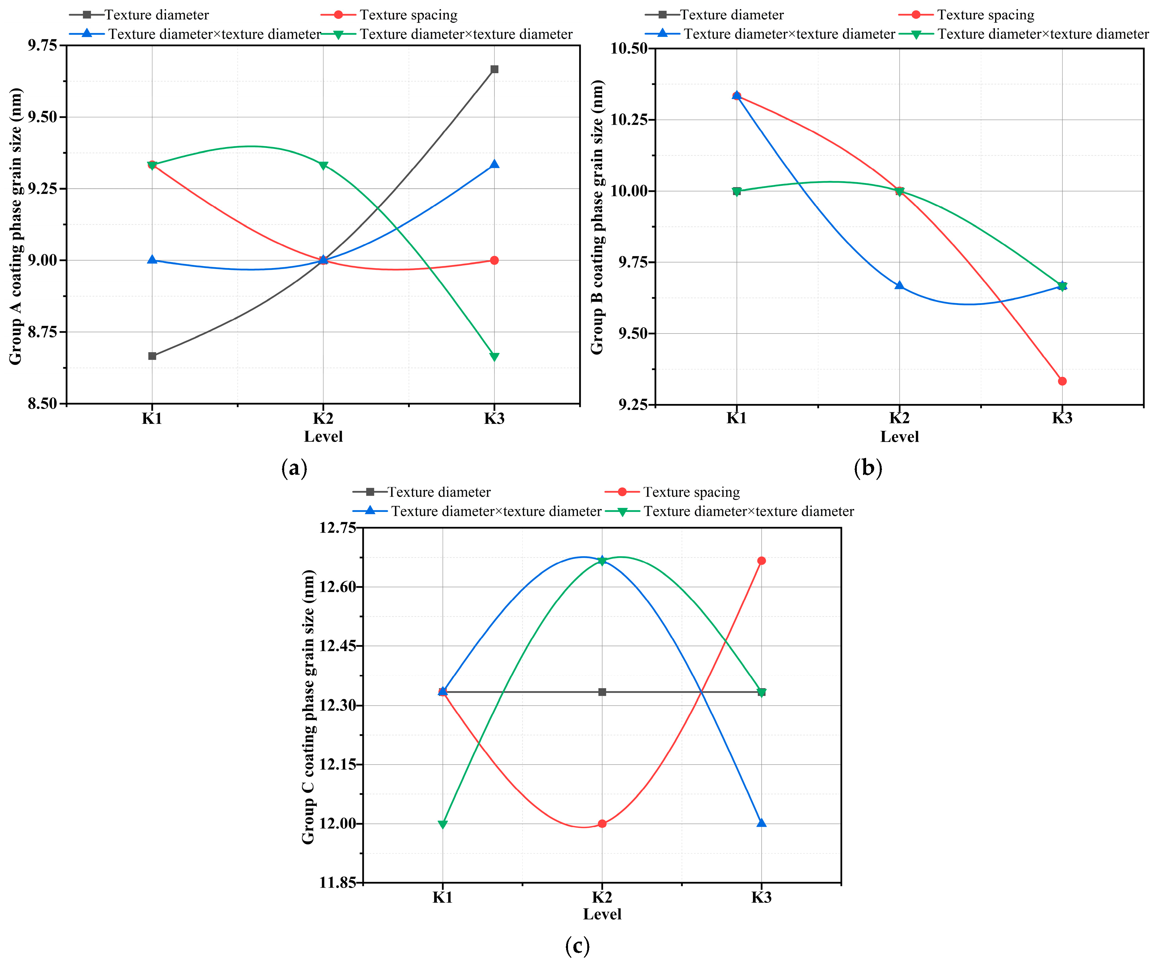
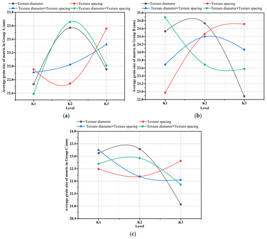
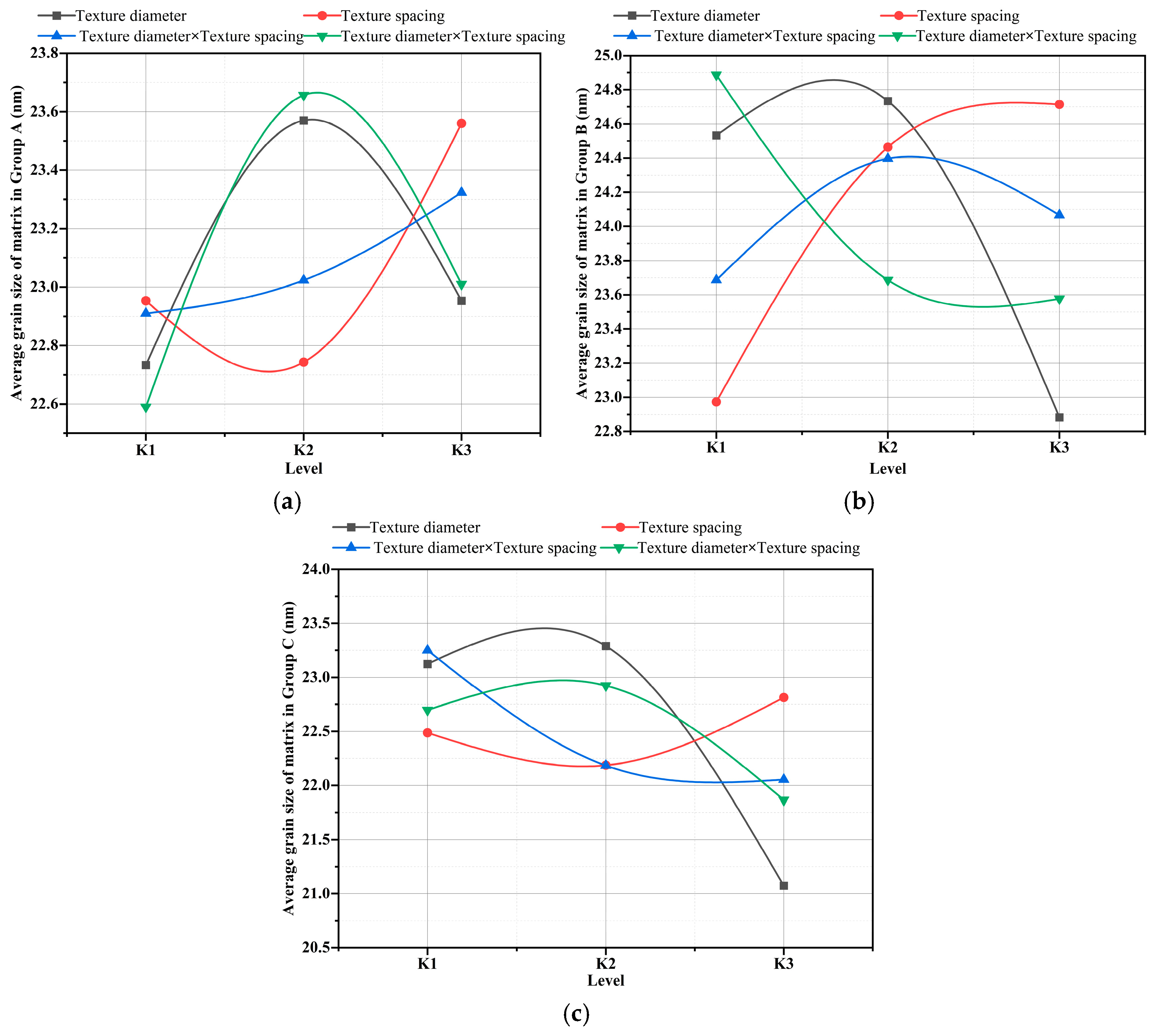
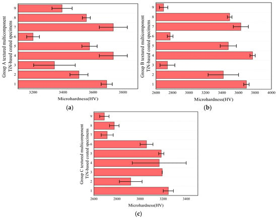
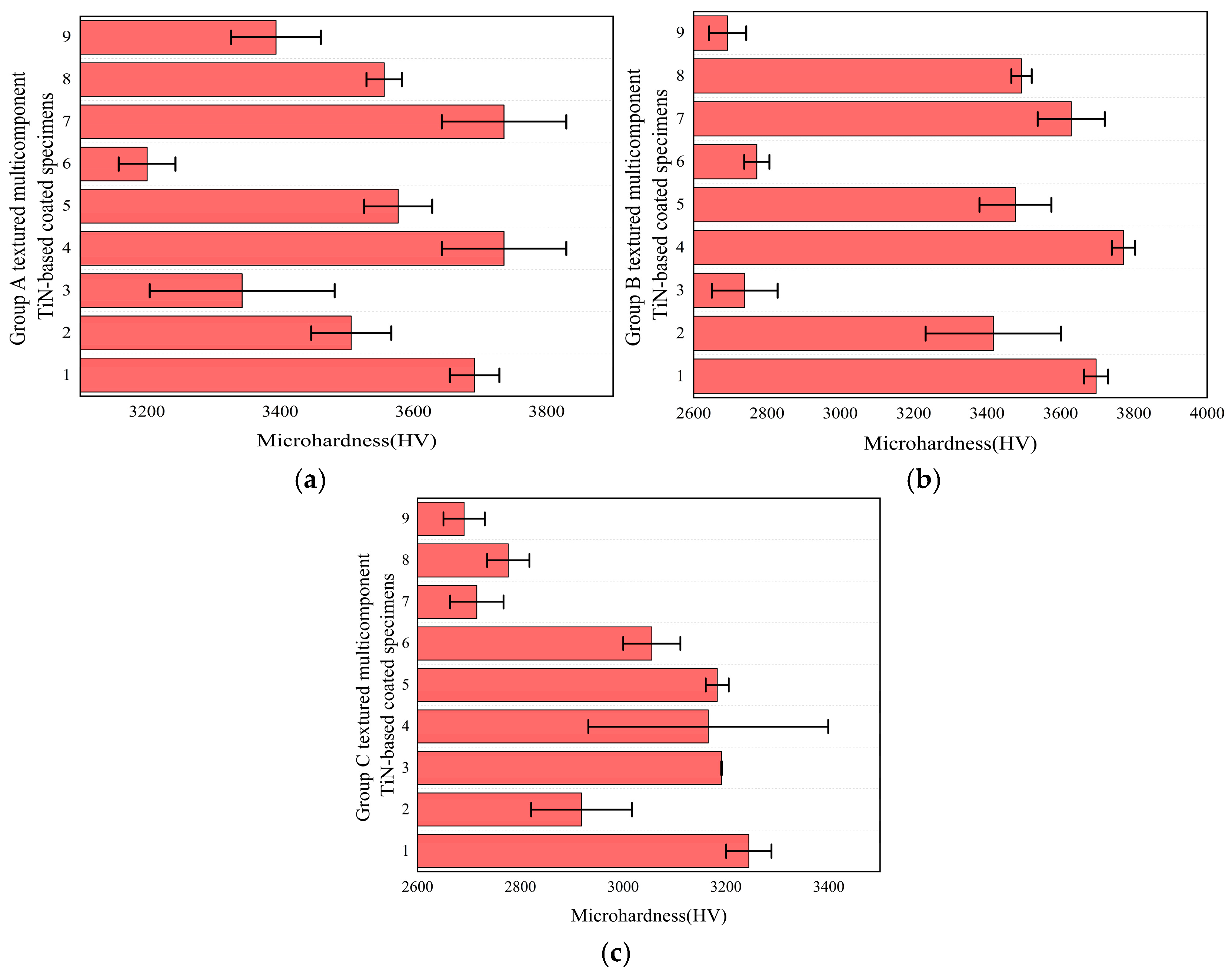
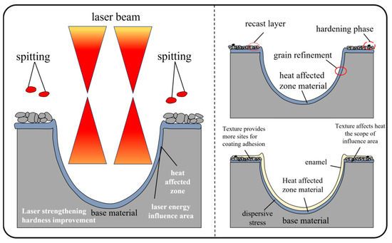
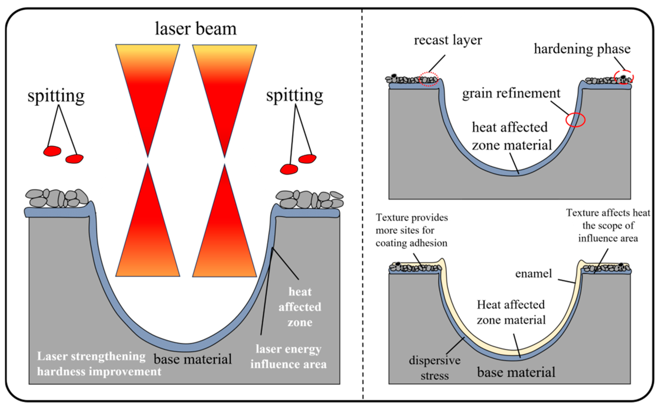
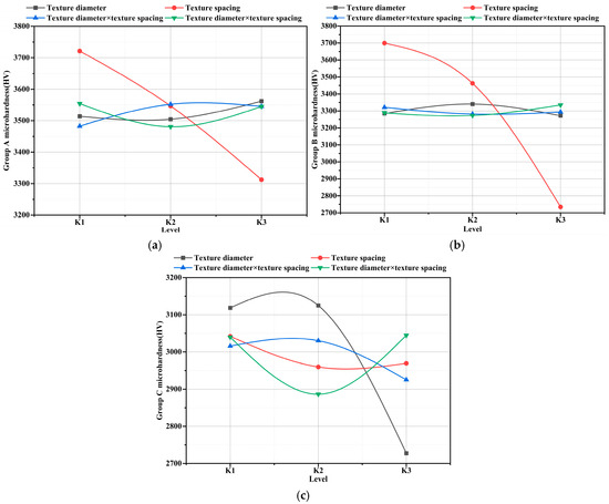
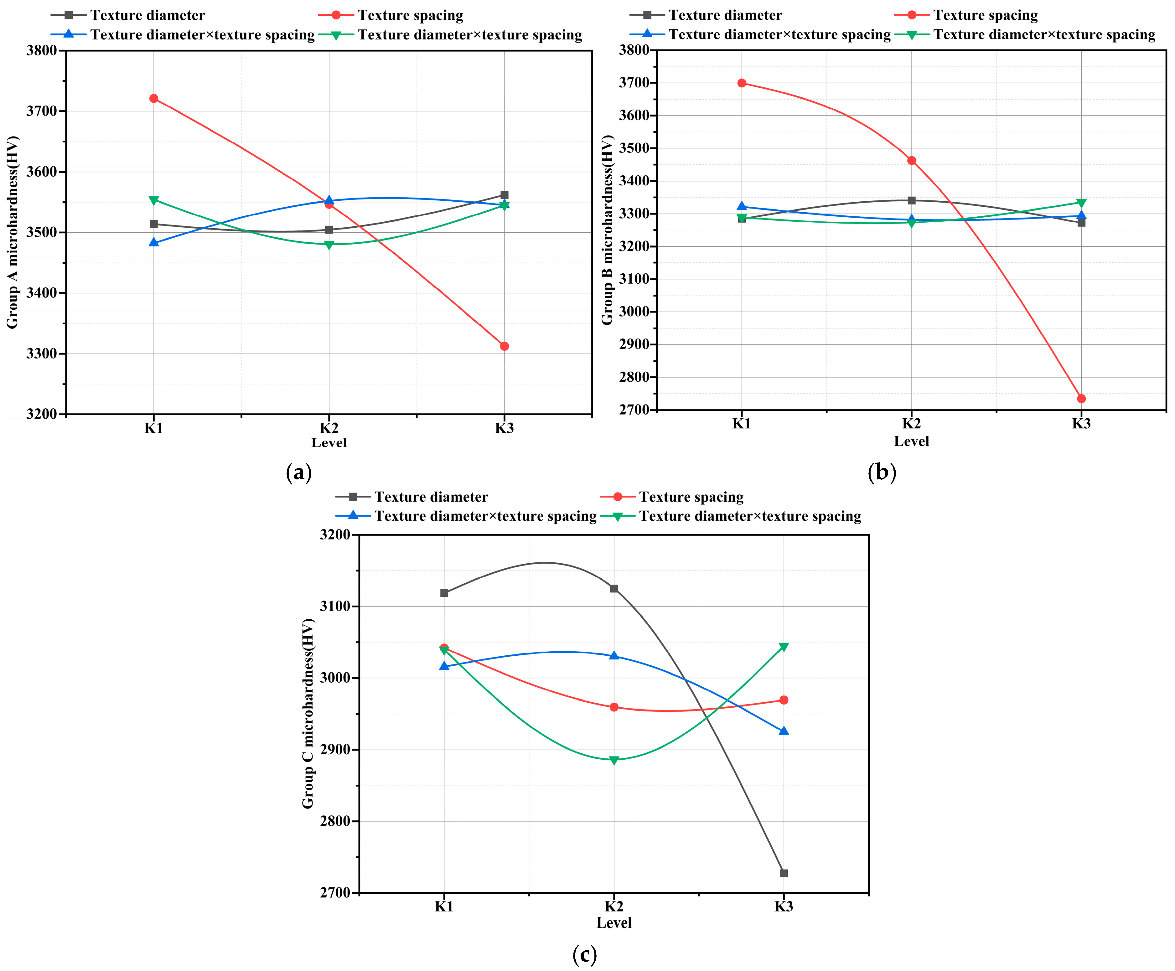
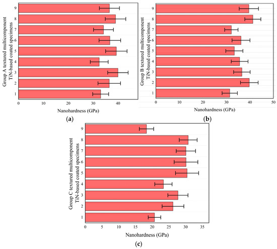
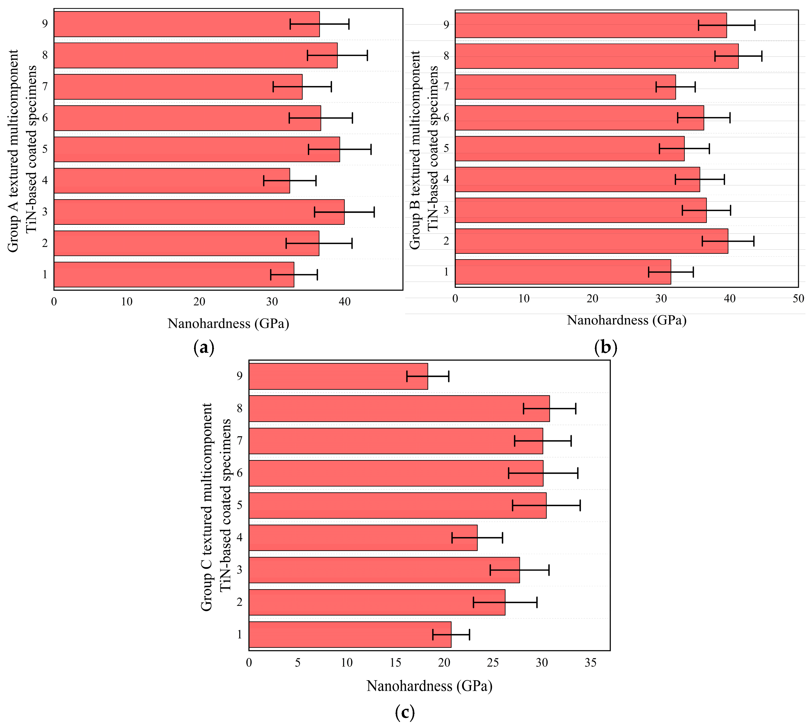
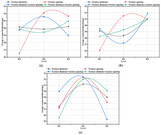
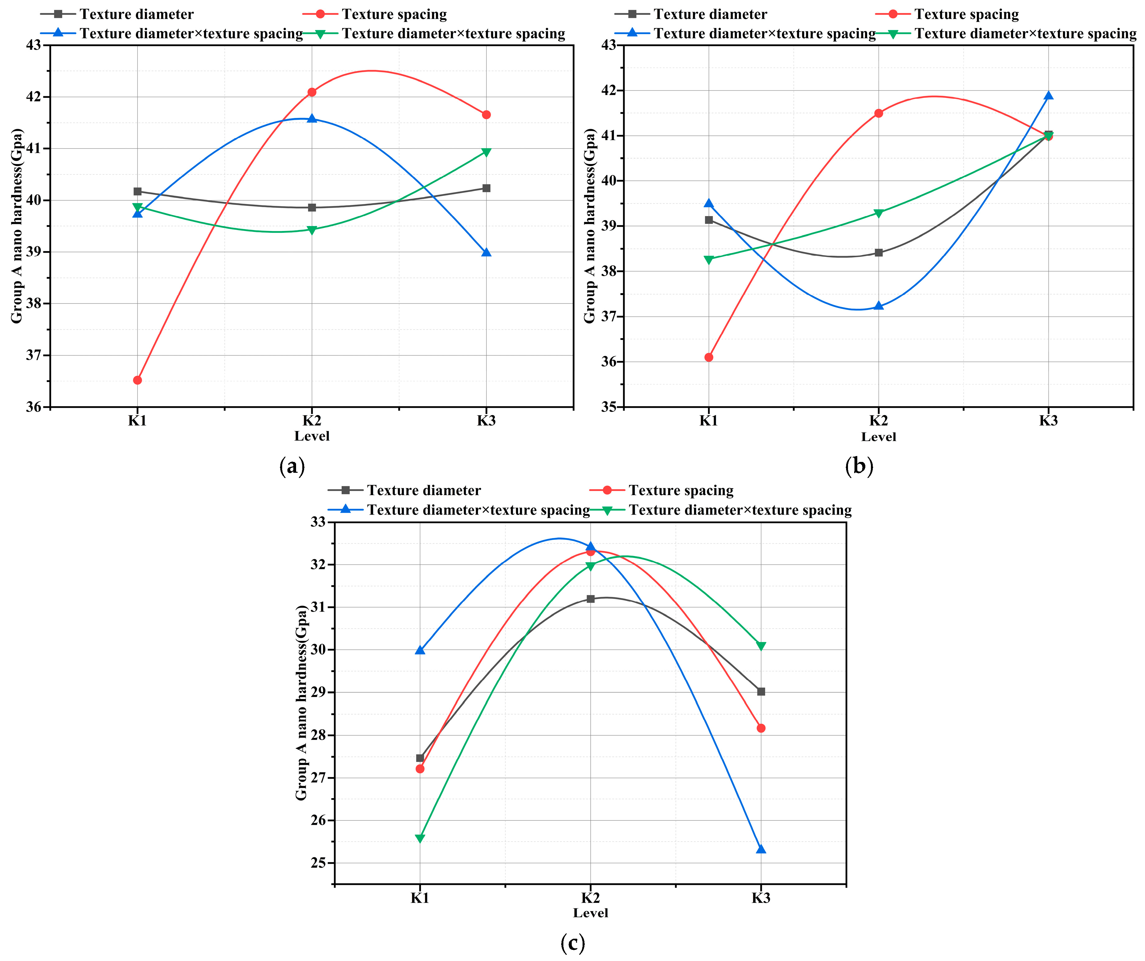
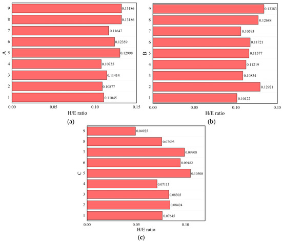
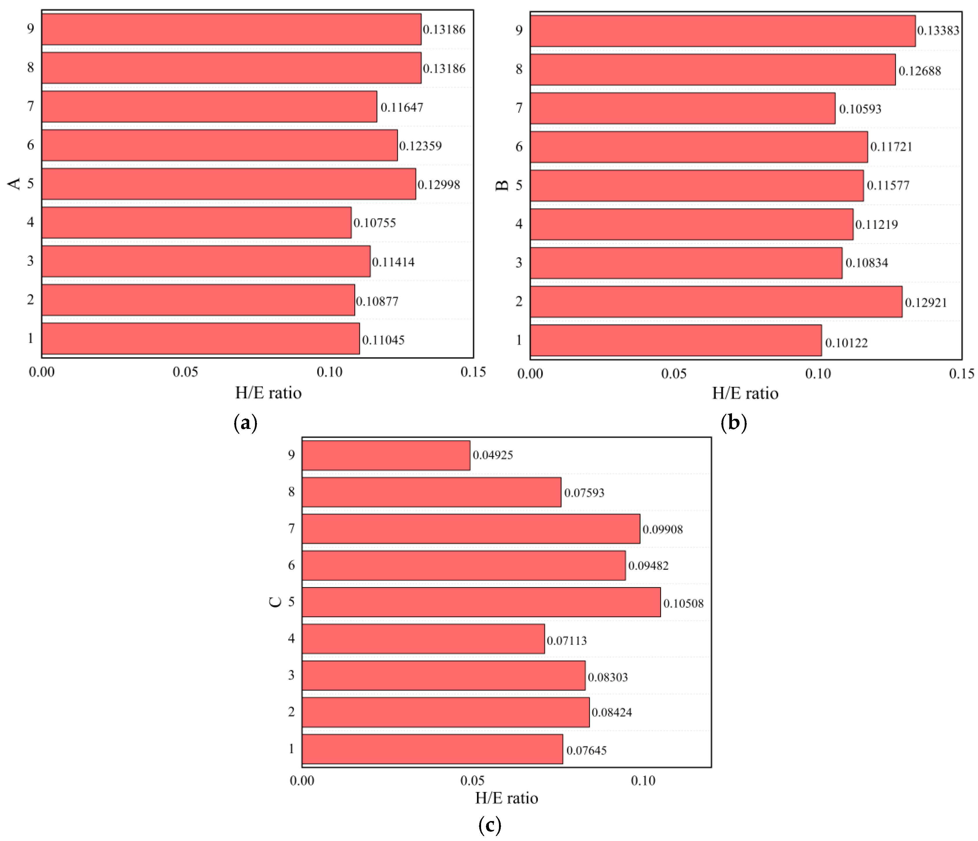
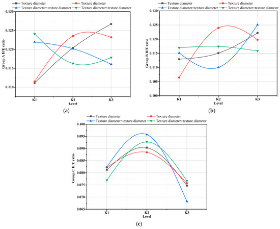
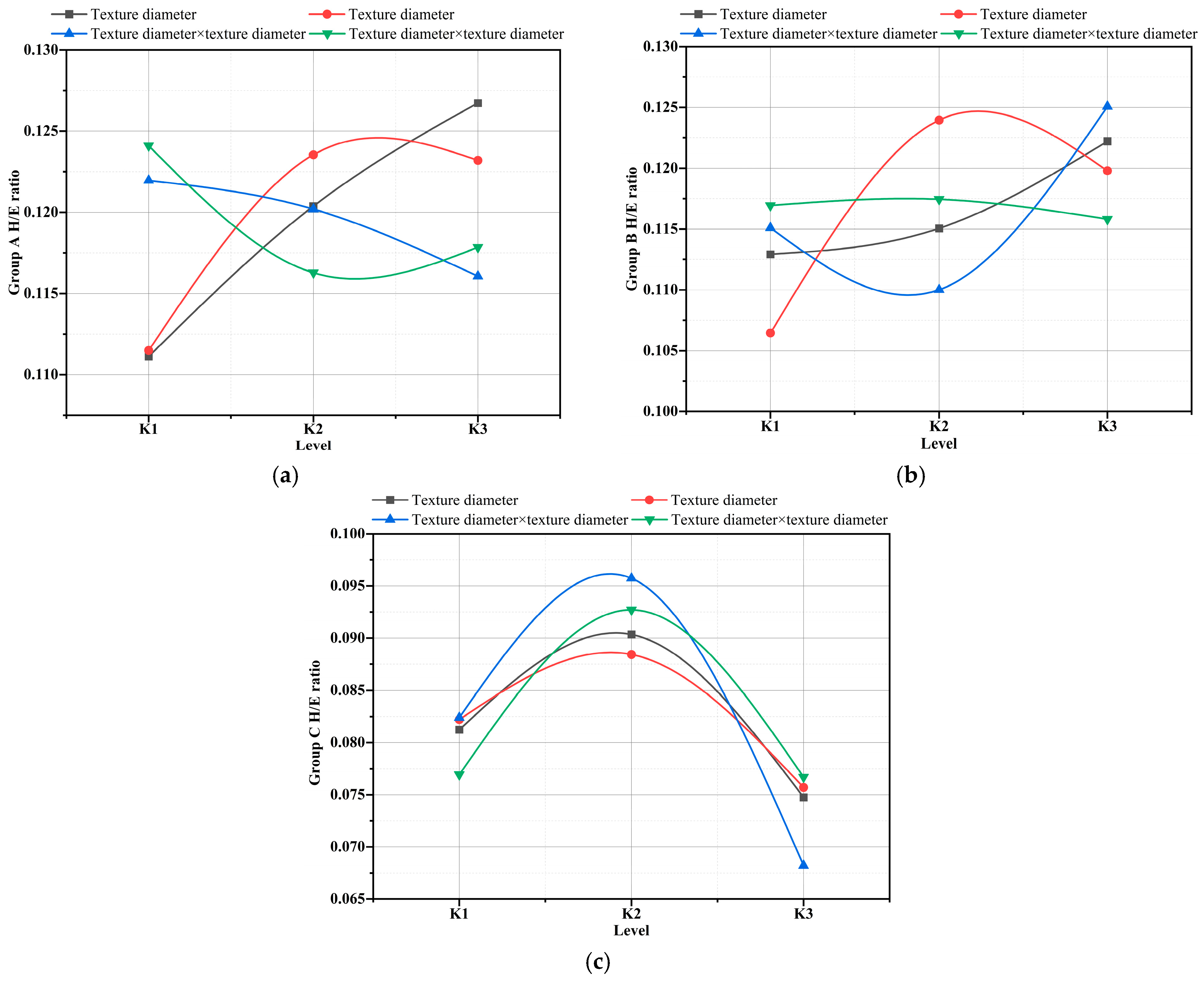
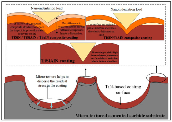
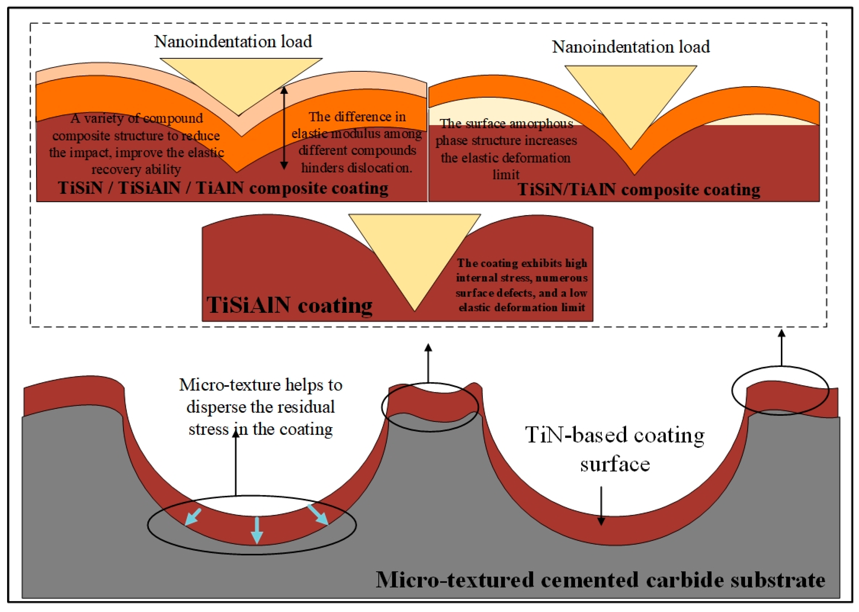

Disclaimer/Publisher’s Note: The statements, opinions and data contained in all publications are solely those of the individual author(s) and contributor(s) and not of MDPI and/or the editor(s). MDPI and/or the editor(s) disclaim responsibility for any injury to people or property resulting from any ideas, methods, instructions or products referred to in the content. |
© 2026 by the authors. Licensee MDPI, Basel, Switzerland. This article is an open access article distributed under the terms and conditions of the Creative Commons Attribution (CC BY) license.