


Abstract
This study numerically investigates the effect of catalytic activity on the cold-start ignition and combustion characteristics of a propane-fueled U-bend catalytic micro-reactor. A reactive-wall approach is employed to model the catalyst coating, wherein catalytic activity is represented by the surface area factor. The results show that surface area factors between 0.425 and 3.4 exert a significant impact on ignition and combustion behavior, reducing the ignition temperature from 682 K to 521 K and decreasing the ignition delay time from 147 s to 52 s while increasing the HTR (heterogeneous reaction) contribution from 26.1% to 65.5%. Beyond a surface area factor of 3.4, performance improvements become marginal. The temporal analysis reveals that the catalytic reaction pathway dominates during the preheating stage, whereas the gas-phase reaction pathway gains prominence following ignition, eventually reaching a stable balance between the two pathways after approximately 10 s. These findings identify low catalytic activity as a sensitive operating regime and underscore the critical role of catalytic activity in optimizing ignition performance of catalytic micro-reactors.
1. Introduction
The growing demand for energy-efficient technologies has spurred considerable interest in small-scale fuel processing systems for both civilian and military applications, particularly for portable power generation and distributed energy production [1,2,3]. Micro-combustion within micro- and meso-scale channels is central to this field, as it enables the efficient utilization of hydrocarbon fuels to drive endothermic reactions or generate electricity via thermoelectric and thermo-photovoltaic devices [4,5,6,7]. However, a major challenge hindering the stability of these systems is the high surface-area-to-volume ratio inherent in miniaturized devices [8,9,10]. This geometric constraint renders homogeneous combustion highly susceptible to thermal and radical quenching [11,12]. Catalytic combustion has emerged as a superior alternative, offering distinct advantages such as an enlarged catalytic surface area and significantly enhanced heat and mass transfer characteristics [8,10]. Numerous studies have demonstrated that catalytic micro-reactors possess wider stability limits and can maintain auto-thermal operation at lower temperatures compared to their purely homogeneous counterparts [13]. Therefore, optimizing catalytic micro-reactors represents a crucial pathway toward achieving reliable and efficient micro-power generation.
The ignition characteristics and flame stability in catalytic micro-reactors have been extensively investigated through both experimental and numerical approaches, particularly focusing on the interplay between heterogeneous (catalytic) and homogeneous (gas-phase) reactions [14,15,16]. Karagiannidis et al. [17,18] conducted a combined experimental and numerical study on lean propane–air mixtures over platinum in catalytic microreactors, revealing that gas-phase chemistry significantly extends the blowout limits at higher inlet velocities. Their work demonstrated that homogeneous ignition could be sustained even at sub-millimeter channel confinements, with the predicted ignition distance deviating by only 19% from experimental values at 7 bar. Similarly, Chen et al. [19] numerically explored the hetero-/homogeneous combustion of propane–air mixtures in platinum-coated micro-reactors, highlighting that an optimum wall thermal conductivity exists for flame stability, which was found to be lower than that required for purely homogeneous systems. Their stability maps indicated that high thermal conductivity materials (e.g., metals) allow operation at higher flow rates, whereas insulating materials (e.g., ceramics) minimize heat losses under low-power conditions.
The role of micro-reactor structure and operating parameters in determining combustion characteristics and stability has been a focal point in previous studies [20,21]. Kaisare and Vlachos [13] performed a comprehensive parametric analysis using a pseudo-two-dimensional model to simulate propane catalytic combustion, identifying that the reactor gap size and wall thickness critically influence heat recirculation and mass transfer. They reported that an optimal gap width of approximately 0.8 mm maximizes stability, while thinner walls lead to hot spots due to large axial temperature gradients. In a complementary study, Di Benedetto et al. [22] proposed a novel hybrid micro-reactor design, dividing the reactor into catalytic and homogeneous sections. Their CFD simulations showed that such a configuration achieves nearly complete fuel conversion at high inlet velocities (up to 30 m/s) by leveraging catalytic preheating to stabilize downstream homogeneous flames, with the maximum wall temperature controlled below 1200 K to prevent catalyst deactivation.
Fundamental insights into the coupling of transport and kinetics have been elucidated through advanced modeling frameworks. Dogwiler et al. [23] developed a two-dimensional model incorporating elementary heterogeneous and homogeneous reactions for methane–air mixtures over platinum, uncovering that the adsorption/desorption of OH radicals and H2O significantly governs homogeneous ignition. Their sensitivity analysis revealed that radical surface interactions shift from net-adsorptive to net-desorptive prior to ignition, emphasizing the need for detailed surface chemistry. Norton and Vlachos [12] further explored homogeneous combustion in microchannels, demonstrating that wall thermal conductivity and external heat losses induce two distinct extinction modes: a global extinction at high conductivities and blowout at low velocities. Their stability diagrams underscored that materials with moderate thermal conductivity (3–5 ) offer the widest operational envelope, balancing heat recirculation and loss mitigation.
The development of high-performance micro-combustors for integrated fuel reforming systems has driven significant innovation, primarily centered on enhancing thermal management, flame stability, and system integration through strategic structural and catalytic interventions [24]. On the structural front, the use of advanced inlet geometries, such as graded-step configurations, has been demonstrated to significantly enhance wall temperature uniformity by over 21% by promoting flame root extension and generating recirculation zones that enhance molecular mixing and heat transfer, thereby addressing the critical issue of thermal gradients that can irreversibly damage downstream reforming catalysts [24,25]. Complementing these geometric advancements, the adoption of catalytic combustion, particularly using platinum for hydrogen-containing mixtures and ruthenium (Ru) for ammonia decomposition, offers a pathway to stable, low-temperature flames that effectively suppress gas-phase combustion, reduce peak temperatures, and consequently cut the formation of thermal NOx by nearly half, as evidenced in integrated reactor designs [25,26]. Furthermore, the system-level integration strategy, including the relative flow direction between the combustor and reformer streams, plays a critical role in performance; for instance, an opposite flow configuration allows the combustion zone to more effectively preheat the reforming reactants, leading to a dramatic increase in hydrogen production [27]. Ultimately, the scalability of these systems is effectively addressed not by enlarging a single unit but by employing a “number amplification” approach—stacking multiple micro-reactor units—which maintains a favorable surface-to-volume ratio to minimize heat loss and preserve high efficiency at larger scales, showcasing a holistic design paradigm for compact, high-flux hydrogen production systems [27].
While the U-bend geometry has been recognized for its superior heat-recirculation capability in enhancing flame stability, previous studies have predominantly treated it merely as a thermal management feature, often overlooking the critical interplay between the geometry and the chemical kinetics at the catalyst surface. The existing literature provides limited insight into how the activity of the catalyst itself governs the ignition and combustion behavior within this specific flow configuration. Our work addresses this gap by systematically investigating the influence of catalytic activity on the ignition and combustion characteristics of propane within a U-bend catalytic micro-reactor. By exploring the role of catalytic activity in key performance metrics such as ignition temperature and ignition delay time, this work provides critical guidance for optimizing catalyst loading and predicting aging effects—key factors influencing both system cost-effectiveness and long-term operational stability. Thus, it bridges a significant gap by linking ignition dynamics with practical catalyst performance considerations in U-bend catalytic micro-reactors.
2. Mathematical Model
2.1. Model Description
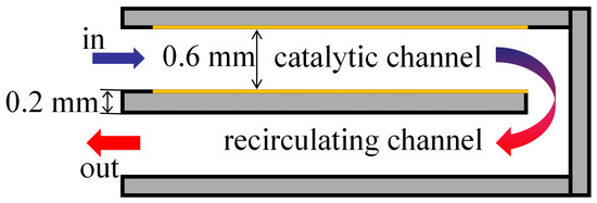
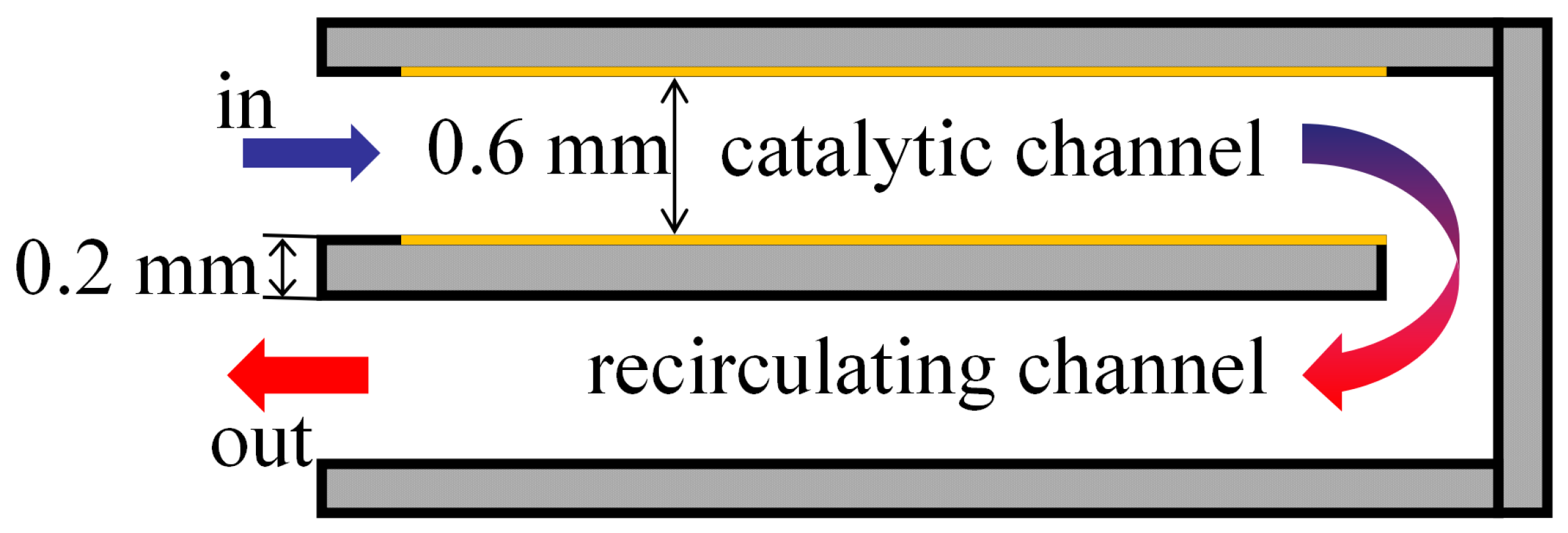
As shown in Figure 1, the physical model under investigation is a U-bend microreactor, consisting of a catalytic channel and a heat-recirculating channel. Each channel has a length of 40 mm, and the gap size—defined as the channel width—is 0.6 mm. The walls separating the two channels have a thickness of 0.2 mm. On the inner wall surface of the catalytic channel, a 1 mm long segment adjacent to the inlet is left uncoated, while the remaining 39 mm section is coated with Pt/Al2O3 catalyst.
Figure 1.
Two-dimensional computational domain of the U-bend micro-reactor under investigation.
The physical model consists of two distinct domains: a solid domain and a fluid domain. A premixed fuel–air mixture is supplied at the inlet and flows into the catalytic channel, where it undergoes catalytic ignition and combustion. The resulting high-temperature products then pass through the heat-recirculating channel before exiting the system, where heat is transferred from the hot combustion products in the recirculating channel back to the catalytic channel, preheating the incoming fresh reactants and thereby enhancing the overall thermal efficiency.
It is worth noting that, although a real catalyst coating possesses a finite physical thickness (typically ranging from a few to tens of microns) in practical devices, it is commonly treated as a zero-thickness surface attached to the gas side of the fluid–solid interface. This simplification is justified when the coating thickness is negligible compared to the characteristic length scale of the channel, as it significantly reduces meshing complexity. By applying reaction kinetics and source terms directly to this catalytic surface, the influence of the catalyst on the flow and thermal fields can be effectively captured without resolving the detailed geometry of the thin layer. The methodology adopted in this work follows this widely accepted modeling practice.
To simplify the computations, the following assumptions are introduced:
- (1)
- The gas-phase mixture is treated as an ideal gas;
- (2)
- The flow in the micro-reactor channels is considered laminar;
- (3)
- The radiation heat transfer in the micro-reactor channels is neglected, given their small dimensions.
The resulting continuity, momentum, energy, and species conservation equations for the fluid phase, along with the energy equation for the solid phase, are presented as follows:
The overall stoichiometric representation of propane oxidation can be expressed as follows:
The homogeneous combustion kinetics of propane are described by a one-step global reaction model as follows [28]:
The catalytic oxidation kinetics of propane are modeled using a simplified one-step mechanism as follows [29]:
Here, and are computed by the following expressions:
where is computed by the following polynomial:
Table 1 provides a list and definitions of the symbols used in the above equations. The specific values of the kinetic rate parameters used in this study for propane catalytic combustion can be found in reference [13].
Table 1.
Nomenclature.
2.2. Meshing, Boundary Conditions, Physical Properties, and Solution Strategy
A structured mesh composed of 183,600 quadrilateral cells is generated for the computational domain, with 2041 axial nodes and 91 lateral nodes. This grid configuration is chosen to provide sufficient resolution for both the fluid and solid phases. The grid density is considered sufficient, as further increases produce no significant variation in critical ignition parameters, including ignition temperature and ignition delay time.
The computational domain is subjected to the following boundary specifications. A constant mass flow rate, corresponding to an inlet velocity of 3 m/s under standard conditions, is imposed at the inlet for a propane–air mixture at an equivalence ratio of 0.6. The outlet is maintained at a constant pressure of 1 atm. A no-slip condition is applied at all fluid–solid interfaces. On the outer wall, thermal management is achieved via convective heat transfer, with a heat transfer coefficient of and an ambient temperature of 300 K, in accordance with Newton’s law of cooling.
Thermophysical properties are defined as follows. For the gas phase, density is determined by the ideal gas law, while thermal conductivity and viscosity are derived from the mass-weighted mixing law. The mass diffusivity is determined based on kinetic theory. The transport properties of individual species are likewise derived from kinetic theory. The specific heat of each species is temperature-dependent and is computed via piecewise polynomial functions. For the solid phase, constant values are assumed for specific heat () and thermal conductivity (). To account for catalytic effects, the surface area factor is taken as a control parameter. This factor is scaled such that the ratio defines the relative catalytic activity. By varying from 0.25 to 10 (corresponding to from 0.425 to 17), the model encompasses a range of catalyst states—from severely degraded conditions (e.g., low loading, poor dispersion, or sintering) at 0.25 (corresponding to = 0.425), to an optimally active configuration (high dispersion and large surface area) at 10 (corresponding to = 17)—thereby enabling a comprehensive investigation of catalytic activity on propane–air ignition characteristics.
Numerical simulations in this work are conducted using the ANSYS Fluent 15.0 software. A user-defined function (UDF) is implemented to incorporate the heterogeneous reaction kinetics. The discretization of the convective terms is handled by a second-order upwind scheme, and the pressure–velocity coupling is addressed via the SIMPLE algorithm. For transient calculations, a time step size of 0.01 s is adopted following a sensitivity analysis. At each time step, solution convergence is deemed to be achieved when the energy residual falls below and residuals for all other equations drop below , accompanied by stabilized values of temperature and propane mass fraction at specified monitoring points.
2.3. Model Validation
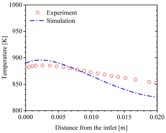
We verified the mathematical model used here by comparing its predictions with published experimental data [30]. In the experiment, a micro-reactor with internal dimensions of 20 mm in length, 3 mm in height, and 10 mm in width was used. The flat panels of the combustor were fabricated from steel and featured a specific heat capacity of 503 . The inner surfaces of these panels were coated with platinum at a surface site density of 2.7 × . A premixed propane/air mixture was introduced into the micro-reactor through an inlet located on one side of the channel.
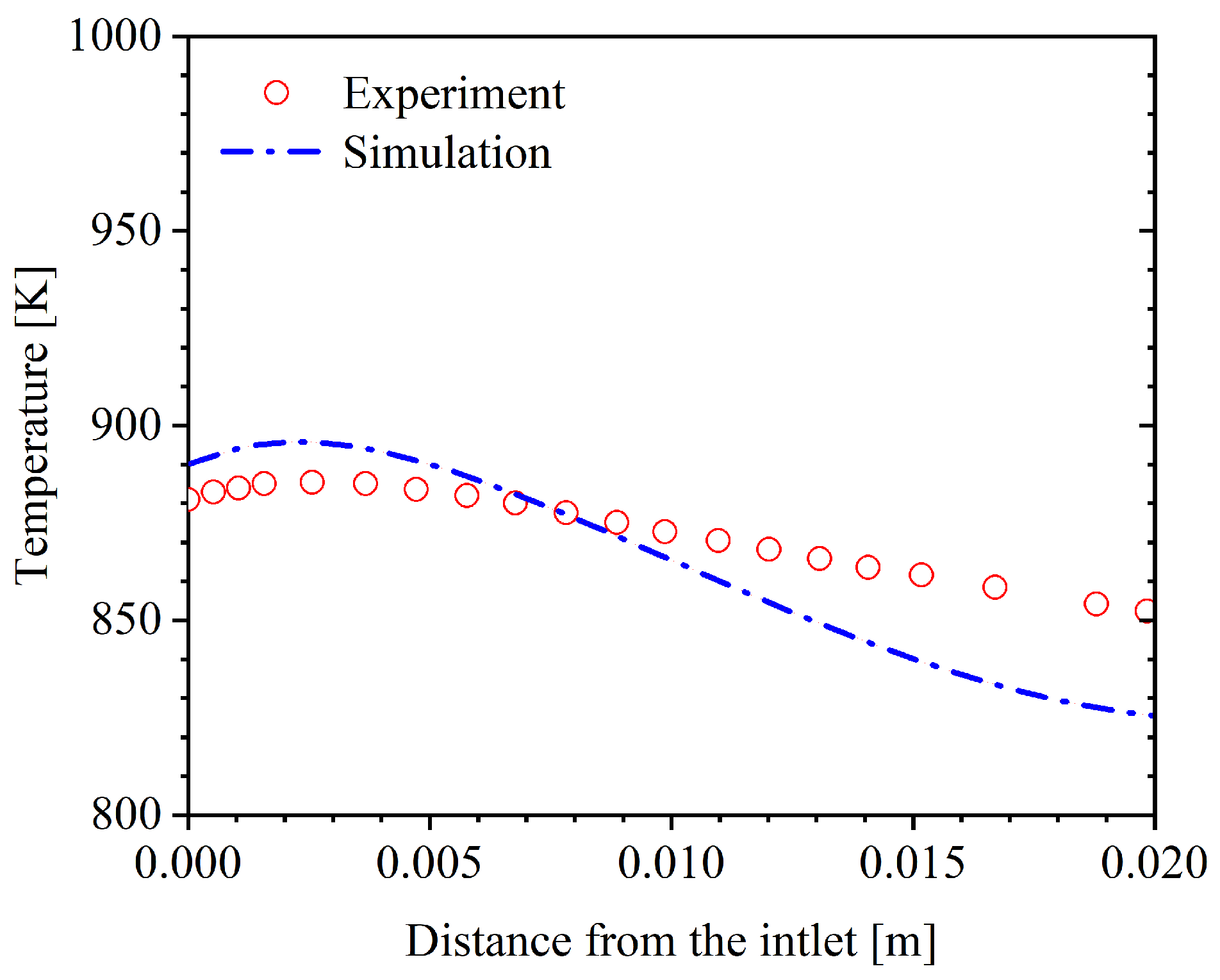
Figure 2 illustrates the comparison of outer-wall temperature distributions between our simulations and the experimental campaign conducted at an inlet velocity of 0.3 and an equivalence ratio of 1.0—a representative operational case. The simulated temperature trends match the measured ones very well; in particular, the location of peak temperature is accurately reproduced. Across matching measurement points, the largest absolute difference is 27 K, equating to a relative discrepancy of about 3.1%. These minor mismatches likely stem from modeling approximations such as employing a simplified one-step global reaction scheme, which can overestimate flame temperatures. Furthermore, the absence of detailed catalyst surface geometry in the computations may add to the disparity. Despite these factors, the low error margin strongly supports the validity of the computational framework, including its chemical kinetics and physical assumptions, for subsequent studies on catalytic microreactor behavior.
Figure 2.
Comparison between numerical results and experimental measurements [30].
3. Results and Discussion
Steady-state simulations were first conducted to determine the ignition temperatures for different catalytic activities, enabling comparison of combustion behavior under various stable conditions. Transient simulations were then performed using inlet temperatures 10 K above the previously determined ignition temperatures to capture the complete evolution from cold start through ignition to stable combustion.
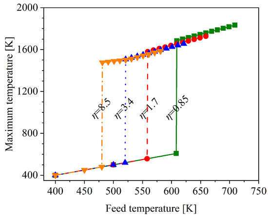
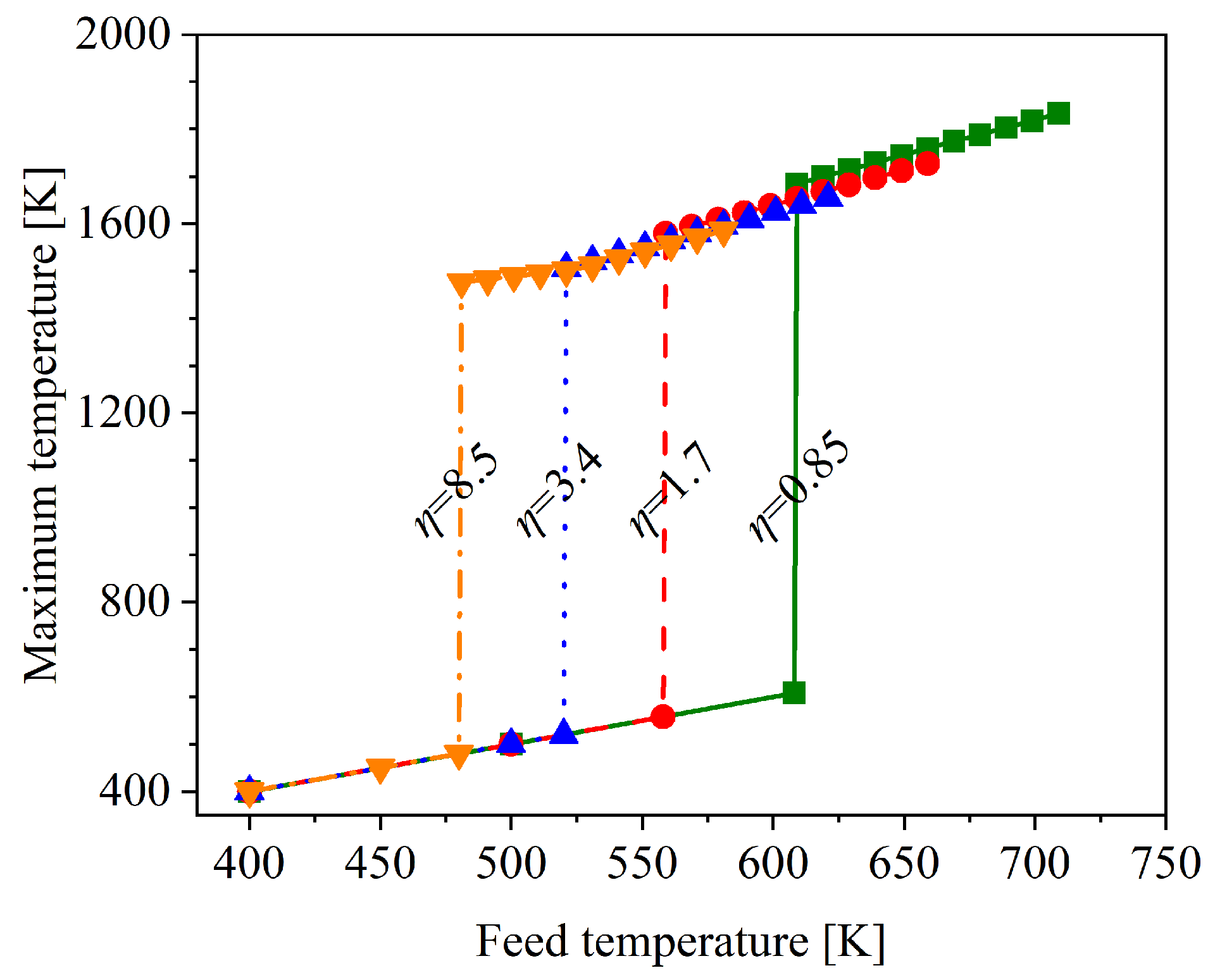
Figure 3 presents the variation of the maximum temperature versus feed temperature for propane oxidation at different surface area factors in the micro-reactor. The observed trend is a direct manifestation of ignition bifurcation. This phenomenon implies that for each surface area factor examined, a specific minimum feed temperature for ignition exists. Below this threshold, the maximum temperature resides on a lower branch where oxidation reactions are weak, resulting in a maximum temperature essentially equal to the feed temperature. Once the feed temperature reaches the threshold, the maximum temperature undergoes a discontinuous jump to an upper branch. Evidently, the ignition temperature increases monotonically with decreasing . Above ignition, the maximum temperature continues to rise with feed temperature steadily for all surface area factors examined. A higher directly lowers the ignition temperature by enhancing the heterogeneous reaction kinetics. With more active area available, a greater number of fuel and oxidizer (e.g., propane and oxygen) can be adsorbed and activated on the surface per unit of time. This increases the frequency of successful surface reactions, thus leading to a greater heat release rate from exothermic surface reactions. The enhanced heat release raises the temperature of both the catalyst surface and the adjacent gas layer more rapidly. This thermal stimulus accelerates the gas-phase reactions nearby. Essentially, A higher provides a more powerful heat accumulation to initiate the global combustion process.
Figure 3.
Variation of maximum temperature with feed temperature at various surface area factors for the catalytic micro-reactor under investigation.
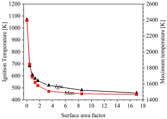
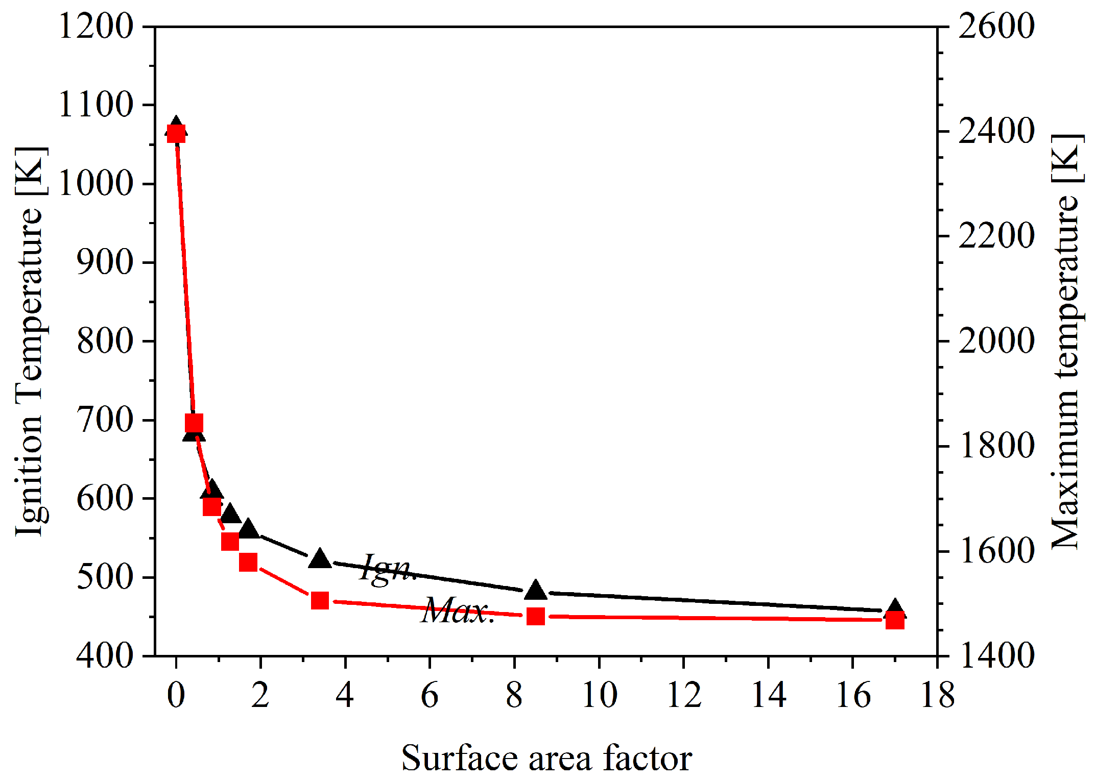
Figure 4 illustrates the sensitivity of both ignition temperature (black triangles) and maximum combustion temperature (red squares) to the surface area factor. For the ignition temperature, there is a sharp decrease as increases from 0.425 to 3.4, after which it plateaus at a relatively low, stable value. Similarly, the maximum combustion temperature exhibits a dramatic drop in the initial increase of from 0.425 to about 3.4, followed by a region of much diminished sensitivity where the maximum combustion temperature remains fairly constant. The figure explicitly demarcates a sensitive region at lower activities and an insensitive region at higher activities for both ignition temperature and maximum combustion temperature.
Figure 4.
Influence of surface area factor on ignition temperature and maximum temperature for the catalytic micro-reactor under investigation.
This trend indicates that plays a crucial role in lowering the energy barrier for the ignition of the propane–air mixture. When is low, even small increases in significantly enhance the reaction kinetics, leading to a substantially lower temperature required for ignition. The maximum combustion temperature also drops markedly, as higher suppresses homogeneous gas-phase reactions. As surpasses the threshold (around 3.4), the reaction is already operating near its kinetically favored regime under these conditions, and mass transfer limitations might start to play a more dominant role. The leveling off of the maximum temperature suggests the combustion process has reached a state of efficient fuel utilization, where the reaction rate is governed more by the mixing of reactants at the catalyst surface rather than the available active area.
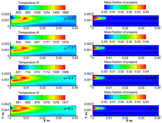
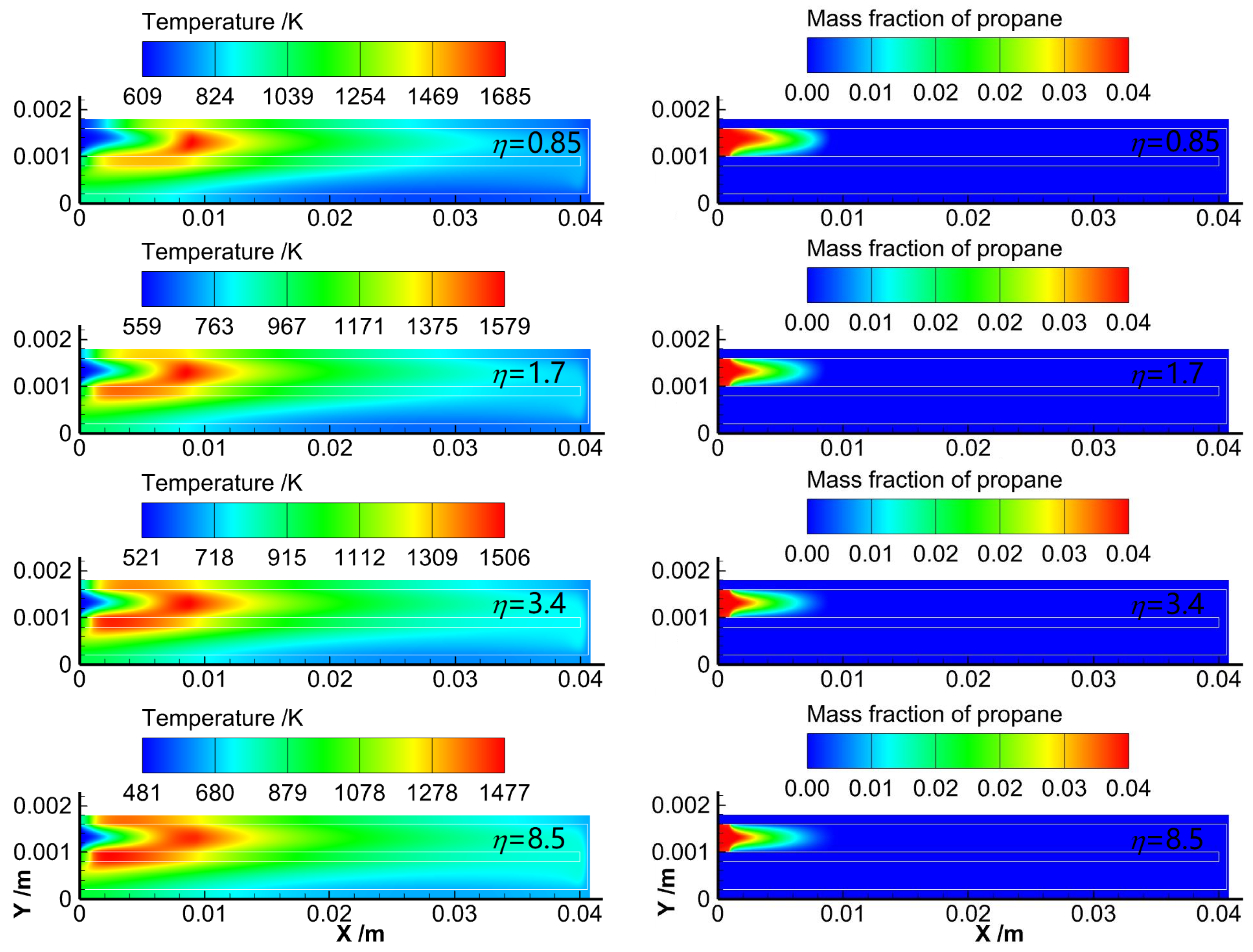
Figure 5 shows the temperature distribution and propane mass fraction distribution within the catalytic micro-reactor under steady-state conditions for of 0.85, 1.7, 3.4, and 8.5. Despite considerable differences in temperature levels for different values, the overall distributions of temperature and propane mass fraction show remarkable similarity. The high-temperature region is primarily located on the catalytic wall near the inlet and extends slightly farther downstream into the central core of the channel. Notably, at = 0.85, the temperature level on the upper catalytic wall near the inlet is lower than that on the lower catalytic surface. This phenomenon can be attributed to the fact that the upper catalytic wall is more susceptible to heat dissipation to the surroundings. However, as increases, this temperature difference becomes less pronounced. The reason is that the catalytic reaction is enhanced, and the heat release from the reaction becomes more dominant compared to heat dissipation.
Figure 5.
Temperature and propane mass fraction distributions at different surface area factors for the catalytic micro-reactor under investigation.
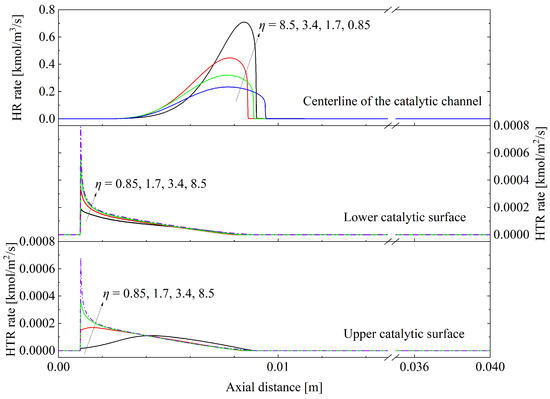
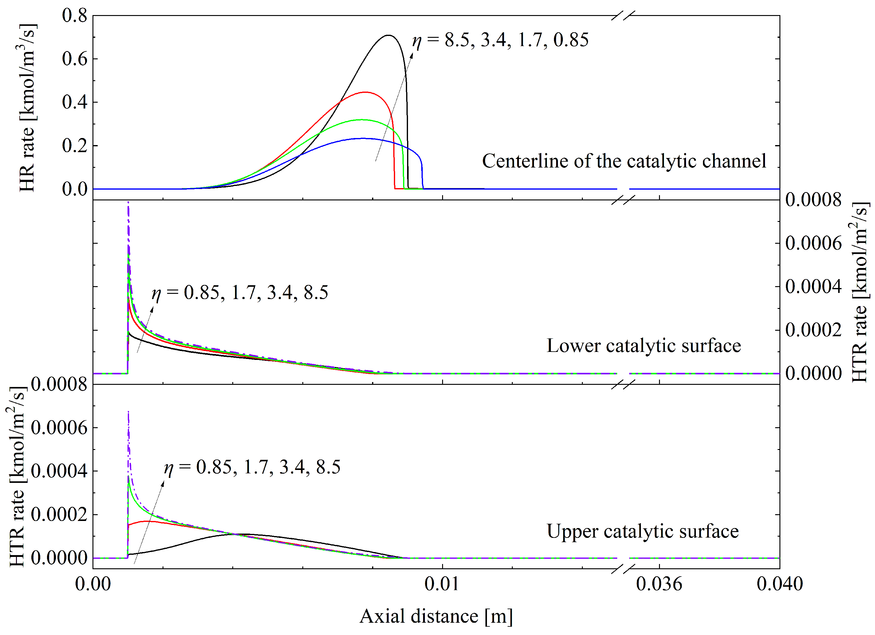
Figure 6 presents the reaction rate distributions along the microchannel for the propane–air mixture, with both the upper and lower inner surfaces coated with catalysts of varying (0.85, 1.7, 3.4, and 8.5). The axial distance represents the flow direction. The HTR and HR correspond to the catalytic reaction rate and gas-phase reaction rate, respectively. At higher (3.4 and 8.5), the reaction rates on both the upper and lower catalytic surfaces decrease monotonically along the flow direction. This suggests that under highly active catalyst conditions, the reaction is primarily limited by the availability of reactants, which are gradually consumed as the flow proceeds. In contrast, for lower values (0.85 and 1.7), the upper catalytic surface exhibits a non-monotonic trend: the reaction rate initially increases before decreasing along the flow direction. This behavior is attributed to the strong temperature dependence of the reaction under low-activity conditions. The upper wall, which is subjected to convective cooling by the surroundings at 300 K, is initially heated by the flow, enhancing the reaction until the rate declines due to limited reactant availability and heat loss. The lower wall, with minimal external heat exchange, shows a consistently decreasing reaction rate, as it is less influenced by thermal loss effects and more by reactant depletion. Overall, the trends highlight the interplay between catalytic activity, heat transfer, and reactant availability in determining the spatial evolution of heterogeneous reactions in the microchannel flows.
Figure 6.
Catalytic and gas-phase reaction rate distributions at different surface area factors for the catalytic micro-reactor under investigation. The line colors correspond to the following surface area factors: black (0.85), red (1.7), green (3.4), blue and purple (8.5).
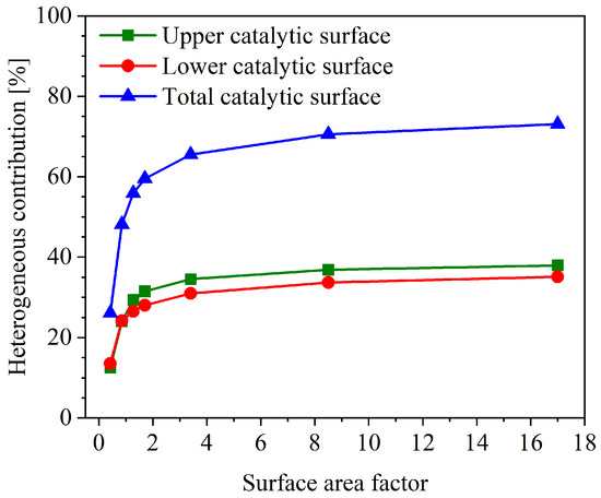
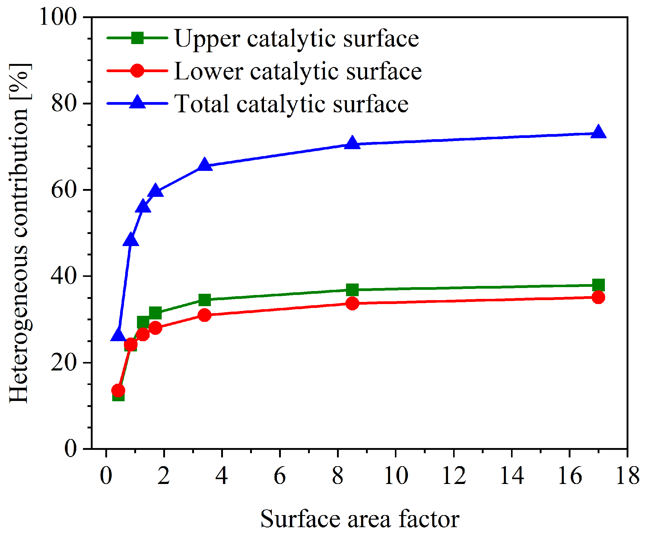
Figure 7 illustrates the HTR contribution as a function of . The HTR contribution is defined as the proportion of propane consumed by catalytic reactions relative to the total propane consumption and is calculated as , where is the propane consumption rate due to catalytic reactions, obtained by integrating the heterogeneous reaction rate (Equation (8)) over the catalyst-coated surface area, and is the propane consumption rate due to gas-phase reactions, obtained by integrating the homogeneous reaction rate (Equation (7)) over the fluid domain.
Figure 7.
HTR contributions at different surface area factors for the catalytic micro-reactor under investigation.
As depicted in Figure 1 (the catalytic walls are indicated by yellow highlighting), the catalytic channel comprises an upper wall and a lower wall, both of which are coated with catalyst. In the Figure 7, the term “upper catalytic surface” refers specifically to the inner surface of the upper wall of the catalytic channel, while the “lower catalytic surface” refers to the inner surface of the lower wall. The “total catalytic surface” is the summation of the upper and lower catalytic surfaces. As increases, the HTR contribution rises significantly, but with distinct sensitivity across different ranges. Specifically, when increases from 0.425 to 3.4, the HTR contribution (total) increases sharply from 26.1% to 65.5%. However, as further increases to 17, the HTR contribution only rises marginally to 73.1%. This indicates that the sensitivity of HTR contribution to is most pronounced in the lower to intermediate range. Beyond this range, further increases in yield diminishing returns, as the HTR contribution becomes limited by other factors like reactant transport and thermal conditions. In addition, for values above 0.85, the HTR contribution of the upper wall is consistently slightly higher than that of the lower wall. These results highlight a nonlinear dependence of HTR contribution on , with a sensitive operational window at lower .
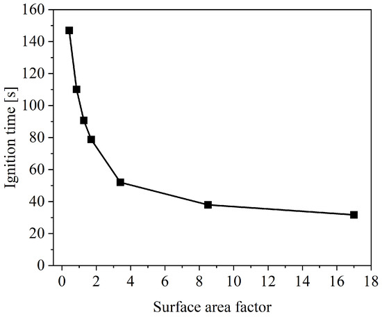
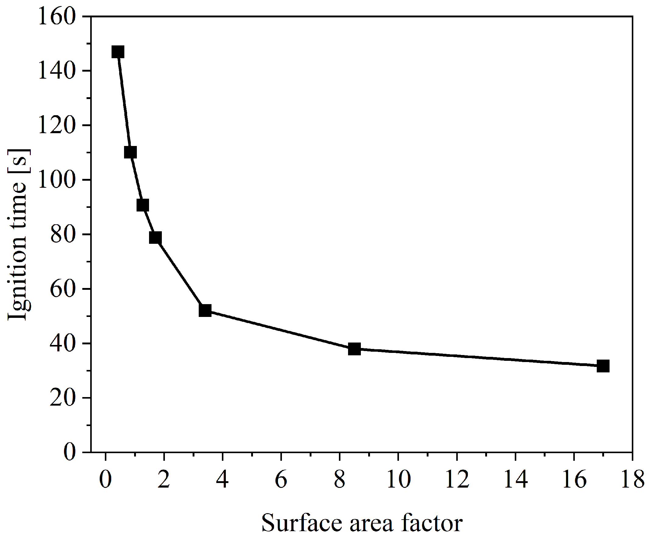
Figure 8 plots the variation of ignition time with surface area factor. As can be observed, when increases from 0.425 to 17, the ignition time decreases significantly from 146.9 s to 31.7 s. The ignition time is highly sensitive to in the low-activity range. Specifically, when drops from 1.7 to 0.425, the ignition time rises sharply from 78.8 s to 146.9 s. Increasing from 1.7 to 3.4 reduces the ignition time to 52 s. However, in the higher activity range (above 8.5), further enhancement in yields only a marginal reduction in ignition time. For instance, doubling from 8.5 to 17 leads to a mere 16.6% decrease in ignition time. This indicates that beyond a certain point, further increases in catalytic activity offer diminishing returns in shortening ignition time. From a practical standpoint, these findings imply that catalyst degradation—due to aging, sintering, or poisoning—can substantially prolong the cold-start ignition period. Therefore, maintaining catalytic activity within a moderate range is crucial for reliable micro-reactor operation, whereas designing for excessively high activity may undermine cost-effectiveness.
Figure 8.
Ignition delay times at different surface area factors for the catalytic micro-reactor at = 1.7.
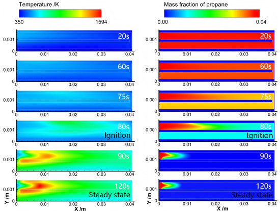
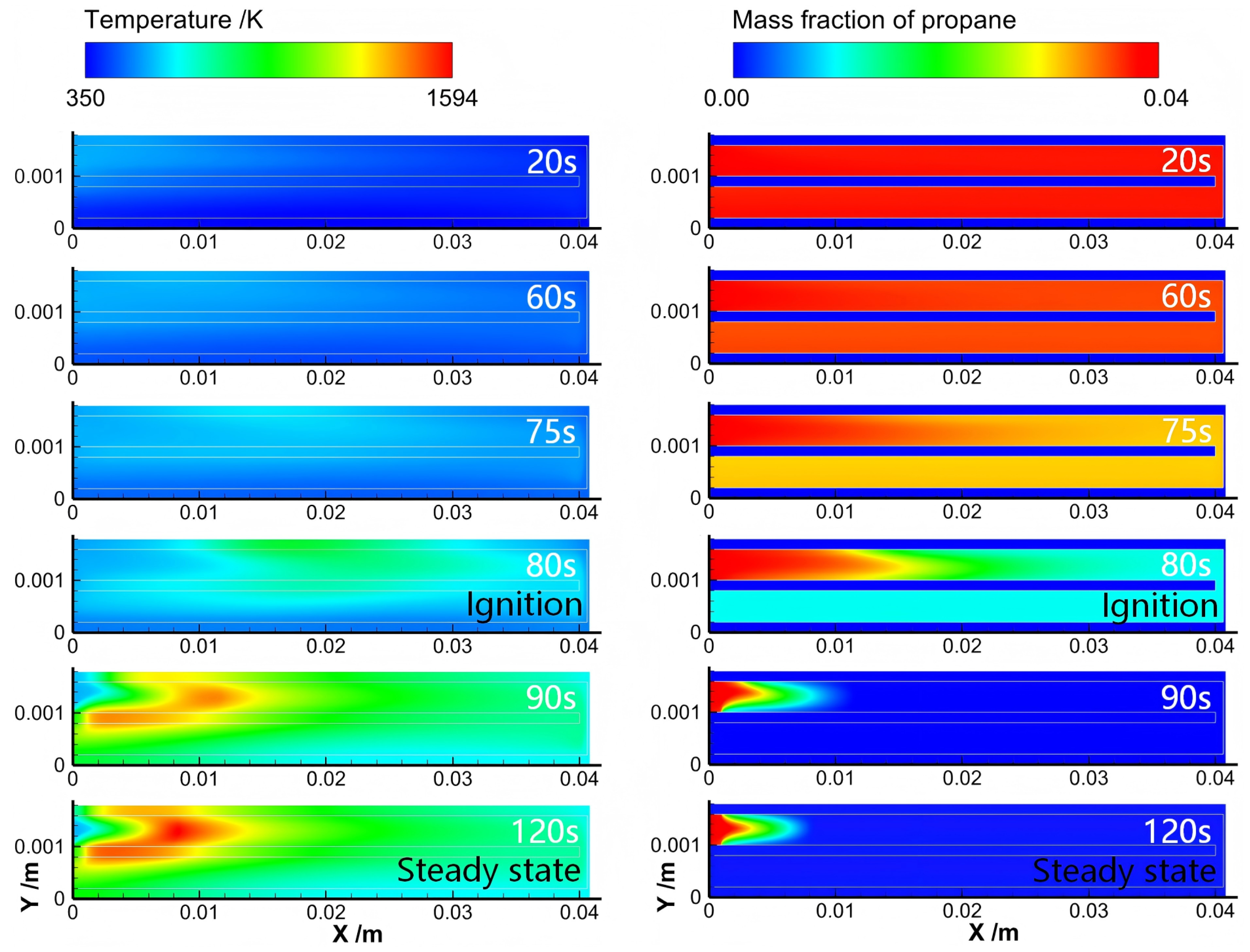
Figure 9 shows the dynamic evolution of temperature and propane mass fraction distributions in the catalytic micro-reactor. At the initial preheating stage (e.g., 20 s), the overall temperature of the micro-reactor remains at a low level. The maximum-temperature zone is located at the entrance end, and the propane mass fraction exhibits negligible reduction and remains the same as that at the inlet. Continued preheating raises the wall temperature, leading to increased heat release from catalytic reactions, while the incoming gas mixture is heated along its flow path. By 75 s, the maximum-temperature region moves downstream, and an easily observed decrease in propane mass fraction signifies considerable reaction intensity. Upon accumulation of sufficient energy in the gas mixture, ignition is initiated. A sharp drop in the propane mass fraction alongside a significant temperature rise at 80 s signifies the occurrence of ignition. Subsequently, the heat released by combustion propagates upstream, heating the incoming mixture and advancing the flame front toward the inlet. At 120 s, a stable combustion state is established near the entrance, where propane is fully consumed within approximately 0.01 m from the inlet, and the high-temperature zone remains anchored upstream.
Figure 9.
Temporal evolution of temperature and propane mass fraction distributions for the catalytic micro-reactor at = 1.7.
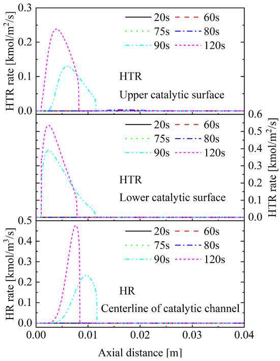
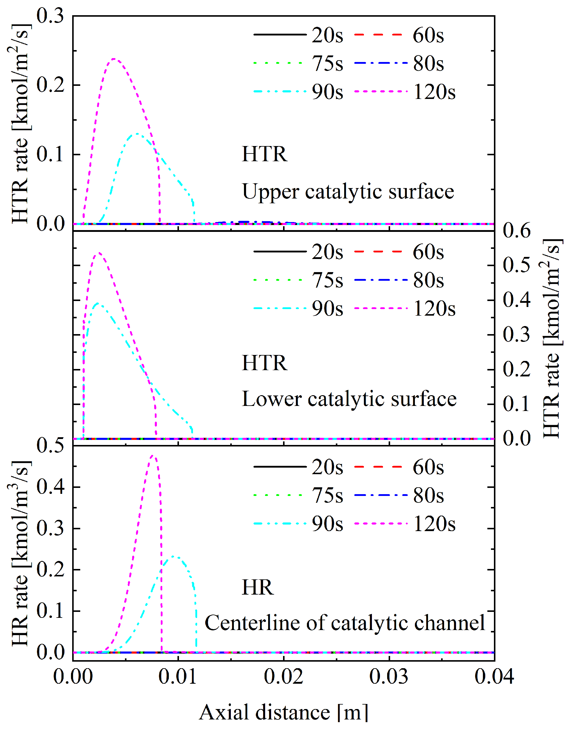
Figure 10 presents the distribution of reaction rate along the micro-reactor length at various time points. The top panel displays the catalytic reaction rate occurring on the upper catalytic wall, the central panel depicts the corresponding rate on the lower catalytic wall, and the bottom panel shows the gas-phase homogeneous reaction rate. During the preheating and initial ignition phases (up to 80 s), all reaction rates remain minimal. A rapid surge in reaction rates occurs within the 10 s following ignition, specifically between 80 and 90 s. From 90 s to 120 s, the peak locations for the gas-phase and upper-wall catalytic reactions shift upstream, eventually stabilizing near the inlet, which is consistent with the temperature profile evolution shown in Figure 9. In contrast, the peak for the lower-wall catalytic reaction remains fixed near the inlet in the meantime. By the steady state, achieved at 120 s, the maximum reaction rates are on the upper wall and on the lower wall, with the upper-wall value notably lower. This discrepancy is attributed to the stronger heat loss from the upper wall to the surroundings, which locally suppresses the catalytic reaction.
Figure 10.
Temporal evolution of catalytic and gas-phase reaction distributions for the catalytic micro-reactor at = 1.7. Note that the black, red, green, and blue lines are almost coincident.
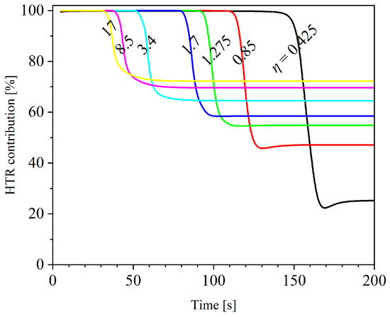
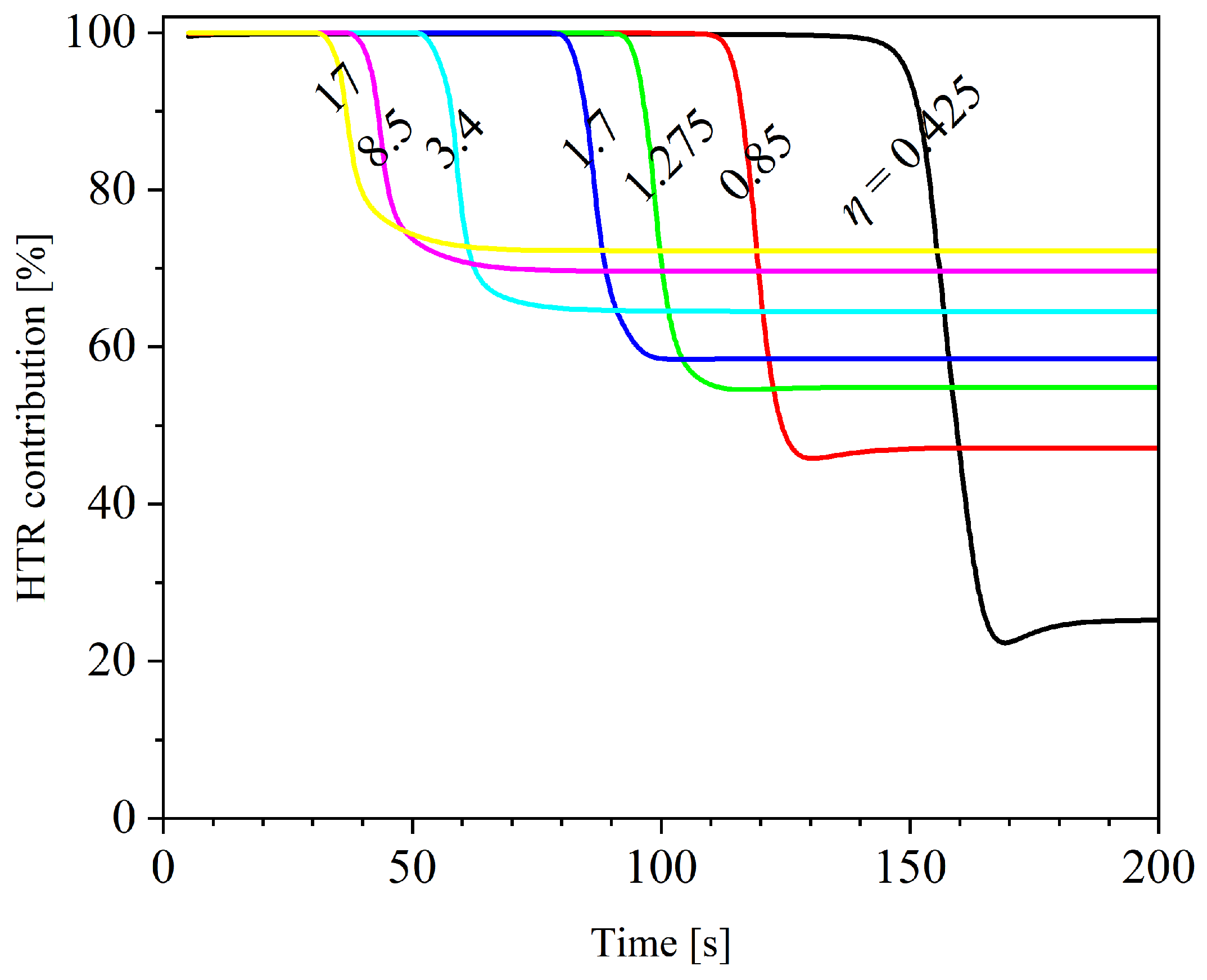
Figure 11 illustrates the temporal evolution of the HTR contribution—the percentage of propane consumed by catalytic reactions relative to the propane total consumption—at various values. Initially, the HTR contribution remains at 100% for all cases due to the low temperature level, which favors the catalytic pathway with its lower activation energy over homogeneous gas-phase reactions. As the micro-reactor is preheated and heat is continually released from catalytic reactions, homogeneous reactions are activated and intensified. Following ignition, a sharp decline is observed in HTR contributions within approximately 10 s across all values examined, after which they tend toward stable states. This transient period is characterized by a coupled interaction between heterogeneous and homogeneous reactions: they are cooperative in thermal enhancement but competitive in acquiring reactants. The HTR contribution at steady state is positively correlated with catalytic activity; a higher results in a greater HTR contribution, as visually confirmed by the results and consistent with the trend shown in Figure 7.
Figure 11.
Temporal evolutions of HTR contributions at different surface area factors for the catalytic micro-reactor.
4. Conclusions
This paper presents a numerical simulation study on the cold-start ignition and combustion performance of a catalytic U-bend micro-reactor, with a specific focus on its sensitivity to catalytic activity. A comparative analysis was conducted on key parameters—including ignition temperature, peak combustion temperature, ignition delay time, reaction rate, and HTR contribution—across various surface area factors.
Numerical results show that the surface area factor range of 0.425–3.4 exerts a significant influence on the ignition and combustion characteristics of the U-bend micro-reactor, whereas a range of 3.4–17 represents a less sensitive region. Specifically, as the surface area factor increases from 0.425 to 3.4, the ignition temperature decreases dramatically from 682 K to 521 K, and the ignition delay time is reduced from 147 s to 52 s, and the HTR contribution rises from 26.1% to 65.5%. However, increasing the surface area factor further from 3.4 to 17 yields diminishing returns: the ignition temperature only drops by 12.3%, the ignition time is shortened by just 20.3 s, and the HTR contribution increases by a mere 11.6%.
For all catalytic activity levels examined in this work, the HTR contribution exhibits a similar characteristic temporal evolution from cold start, despite differences in ignition delay time. During the preheating stage, the catalytic reaction pathway dominates completely. Following ignition, the gas-phase reaction pathway gradually gains prominence, leading to a decline in the HTR contribution. After approximately 10 s of competitive transition, the system reaches a stable equilibrium between the two pathways.
From a practical standpoint, these results suggest that catalyst degradation—from aging, sintering, or poisoning—can significantly delay cold-start ignition and raise the maximum combustion temperature. Keeping catalytic activity in a moderate range is key to reliable micro-reactor operation, while overly high activity can undermine cost-efficiency. Potential avenues for future work include incorporating modeling of the catalyst coating, taking into account its thickness, micropore structure, and internal mass diffusion, and a more detailed chemical kinetic mechanism for propane–air combustion to investigate the effects of platinum concentration, loading, and distribution on ignition and combustion performance in micro-reactors.
Author Contributions
Z.L.: Conceptualization, Methodology, Formal analysis, Validation, Writing—original draft; M.Y.: Methodology, Investigation, Formal analysis, Data curation, Writing—original draft; J.B.: Investigation, Formal analysis, Validation; H.Y.: Data curation, Visualization; X.W.: Investigation, Formal analysis, Visualization; Z.W.: Writing—review and editing, Supervision, Funding Acquisition; G.W.: Writing—review & editing, Funding Acquisition; Z.Y.: Software, Supervision, Project administration. All authors have read and agreed to the published version of the manuscript.
Funding
This research was supported by the Scientific Research Fund of Binzhou Polytechnic University (Grant No. 26-ZJZX-021).
Institutional Review Board Statement
Not applicable.
Informed Consent Statement
Not applicable.
Data Availability Statement
The datasets are made available upon reasonable request to the corresponding author.
Acknowledgments
The authors are grateful to many colleagues with whom they have had the privilege to interact and collaborate over the years and whose work is partially referenced in this article.
Conflicts of Interest
The authors declare that the research was conducted in the absence of any commercial or financial relationships that could be construed as a potential conflict of interest.
References
- Regatte, V.R.; Kaisare, N.S. Propane combustion in non-adiabatic microreactors: 2. Flow configuration in post microreactors. Chem. Eng. Sci. 2011, 66, 3732–3741. [Google Scholar] [CrossRef] [Scilit]
- Burra, K.R.G.; Sahin, M.; Gupta, A.K. Resistive heating catalytic micro-reactor for process intensified fuel reforming to hydrogen. J. Energy Resour. Technol. 2024, 146, 092102. [Google Scholar] [CrossRef] [Scilit]
- Yedala, N.; Kaisare, N.S. Design of microcombustor–thermoelectric coupled device using a CFD-based multiphysics model for power generation. React. Chem. Eng. 2024, 9, 2135–2148. [Google Scholar] [CrossRef] [Scilit]
- Kaisare, N.S.; Vlachos, D.G. A review on microcombustion: Fundamentals, devices and applications. Prog. Energy Combust. Sci. 2012, 38, 321–359. [Google Scholar] [CrossRef] [Scilit]
- Ju, Y.; Maruta, K. Microscale combustion technology: Development and fundamental research. Prog. Energy Combust. Sci. 2011, 37, 669–715. [Google Scholar] [CrossRef] [Scilit]
- Federici, J.A.; Norton, D.G.; Brüggemann, T.; Voit, K.W.; Wetzel, E.D.; Vlachos, D.G. Catalytic microcombustors with integrated thermoelectric elements for portable power production. J. Power Sources 2006, 161, 1469–1478. [Google Scholar] [CrossRef] [Scilit]
- Jiang, D.; Yang, W.; Chua, K.J.; Ouyang, J.; Teng, J. Effects of H2/CO blend ratio on radiated power of micro combustor/emitter. Appl. Therm. Eng. 2015, 86, 178–186. [Google Scholar]
- Kommu, M.; Kaisare, N.S. Ignition of homo/hetero combustion of propane in a microreactor with catalyst segmentation. Chem. Eng. Res. Des. 2018, 138, 125–134. [Google Scholar] [CrossRef] [Scilit]
- Dong, G.; Chen, B.; Liu, B.; Hounjet, L.J.; Cao, Y.; Stoyanov, S.R.; Yang, M.; Zhang, B. Advanced oxidation processes in microreactors for water and wastewater treatment: Development, challenges, and opportunities. Water Res. 2022, 211, 118047. [Google Scholar] [CrossRef] [Scilit]
- da Silva, J.L., Jr.; Santana, H.S.; Hodapp, M.J. Microreactor technology applied to catalytic processing of hydrogen: A review. J. Ind. Eng. Chem. 2025, 143, 65–84. [Google Scholar] [CrossRef] [Scilit]
- Aghalayam, P.; Bui, P.-A.; Vlachos, D.G. The role of radical wall quenching in flame stability and wall heat flux: Hydrogen-air mixtures. Combust. Theory Model. 1998, 2, 515–530. [Google Scholar] [CrossRef] [Scilit]
- Norton, D.G.; Vlachos, D.G. Combustion characteristics and flame stability at the microscale: A CFD study of premixed methane/air mixtures. Chem. Eng. Sci. 2003, 58, 4871–4882. [Google Scholar] [CrossRef] [Scilit]
- Kaisare, N.S.; Deshmukh, S.R.; Vlachos, D.G. Stability and performance of catalytic microreactors: Simulations of propane catalytic combustion on Pt. Chem. Eng. Sci. 2008, 63, 1098–1116. [Google Scholar] [CrossRef] [Scilit]
- Ma, L.; Wang, M.; Lu, B.; Li, W.; Zhai, W.; Zhou, B.; Li, Z.; Wang, Z. Numerical study of external heat loss effects on propane ignition characteristics in a catalytic microreactor. J. Phys. Conf. Ser. 2025, 3159, 012005. [Google Scholar] [CrossRef] [Scilit]
- Wang, Z.; Wang, Z.; Miao, Z.; Ma, L.; Xu, W.; Li, Z.; Yang, Z.; Jiang, G. Propane ignition characteristics in a Pt-catalyzed microreactor for SOFC preheating: A numerical study of catalyst activity effects. Batteries 2025, 11, 390. [Google Scholar] [CrossRef] [Scilit]
- Regatte, V.R.; Selle, G.; Kaisare, N.S. The role of homogeneous chemistry during ignition of propane combustion in Pt-catalyzed microburners. Int. J. Spray Combust. Dyn. 2012, 4, 155–174. [Google Scholar] [CrossRef] [Scilit]
- Karagiannidis, S.; Mantzaras, J.; Jackson, G.; Boulouchos, K. Hetero-/homogeneous combustion and stability maps in methane-fueled catalytic microreactors. Proc. Combust. Inst. 2007, 31, 3309–3317. [Google Scholar] [CrossRef] [Scilit]
- Karagiannidis, S.; Mantzaras, J.; Bombach, R.; Schenker, S.; Boulouchos, K. Experimental and numerical investigation of the hetero-/homogeneous combustion of lean propane/air mixtures over platinum. Proc. Combust. Inst. 2009, 32, 1947–1955. [Google Scholar] [CrossRef] [Scilit]
- Chen, J.; Song, W.; Gao, X.; Xu, D. Hetero-/homogeneous combustion and flame stability of fuel-lean propane-air mixtures over platinum in catalytic micro-combustors. Appl. Therm. Eng. 2016, 100, 932–943. [Google Scholar] [CrossRef] [Scilit]
- Fernández-Maza, C.; Fallanza, M.; Gómez-Coma, L.; Ortiz, I. Performance of continuous-flow micro-reactors with curved geometries. Experimental and numerical analysis. Chem. Eng. J. 2022, 437, 135192. [Google Scholar] [CrossRef] [Scilit]
- Esfandiary, M.; Saedodin, S.; Karimi, N. On the effects of surface waviness upon catalytic steam reforming of methane in micro-structured reactors—A computational study. Int. J. Hydrogen Energy 2024, 52, 465–481. [Google Scholar] [CrossRef] [Scilit]
- Di Benedetto, A.; Di Sarli, V.; Russo, G. A novel catalytic-homogeneous micro-combustor. Catal. Today 2009, 147, S156–S161. [Google Scholar] [CrossRef] [Scilit]
- Dogwiler, U.; Benz, P.; Mantzaras, J. Two-dimensional modelling for catalytically stabilized combustion of a lean methane-air mixture with elementary homogeneous and heterogeneous chemical reactions. Combust. Flame 1999, 116, 243–258. [Google Scholar] [CrossRef] [Scilit]
- Luo, B.; E, J.; Feng, C.; Ding, J.; Yang, W. Investigation on performance optimization of a novel microreactor with multiple-pulsation combustion for methanol steam reforming to hydrogen production for proton exchange membrane fuel cell. Appl. Energy 2025, 384, 125488. [Google Scholar] [CrossRef] [Scilit]
- Zhong, Y.; Zhou, W.; Zhou, S.; Li, X.; Chu, X.; Wu, L. Development of large-flux laminated methanol reforming microreactor heated by methanol catalytic combustion. Int. J. Hydrogen Energy 2024, 54, 1110–1119. [Google Scholar] [CrossRef] [Scilit]
- Zhang, E.; Zhang, F.; Ren, Z.; Sui, R. Decomposition of NH3 and subsequent combustion in an integrated Ru-/Pt-catalytic microreactor. Ind. Eng. Chem. Res. 2025, 65, 361–366. [Google Scholar] [CrossRef] [Scilit]
- Zheng, T.; Zhou, D.; Zhan, Y.; Xu, Y. Integration design optimization of self-thermal methanol steam reforming microreactor for hydrogen production. Int. J. Hydrogen Energy 2023, 48, 32642–32653. [Google Scholar] [CrossRef] [Scilit]
- Westbrook, C.K.; Dryer, F.L. Simplified reaction mechanisms for the oxidation of hydrocarbon fuels in flames. Combust. Sci. Technol. 1981, 27, 31–43. [Google Scholar] [CrossRef] [Scilit]
- Deshmukh, S.R.; Vlachos, D.G. A reduced mechanism for methane and one-step rate expressions for fuel-lean catalytic combustion of small alkanes on noble metals. Combust. Flame 2007, 149, 366–383. [Google Scholar] [CrossRef] [Scilit]
- Lu, Q.; Zhou, H.; Zhang, Y.; Gou, J.; Fan, B.; Jiang, C.; Yang, W.; Yuan, J.; Pan, J. Experimental and numerical investigations on hetero-/homogeneous combustion characteristics of C3H8/Air mixtures in the micro catalytic combustor. Appl. Therm. Eng. 2025, 274, 126638. [Google Scholar] [CrossRef] [Scilit]

Disclaimer/Publisher’s Note: The statements, opinions and data contained in all publications are solely those of the individual author(s) and contributor(s) and not of MDPI and/or the editor(s). MDPI and/or the editor(s) disclaim responsibility for any injury to people or property resulting from any ideas, methods, instructions or products referred to in the content. |
© 2026 by the authors. Licensee MDPI, Basel, Switzerland. This article is an open access article distributed under the terms and conditions of the Creative Commons Attribution (CC BY) license.