


Abstract
Carbon Fiber Reinforced Polymer (CFRP)-strengthened steel plate systems demonstrate remarkable advantages in civil engineering structural rehabilitation, with their overall performance critically reliant on the interfacial bond behavior between CFRP and steel plates. This paper systematically reviews the typical failure modes, key factors influencing interfacial bond performance, and corresponding testing methodologies. Research indicates that interfacial shear stress dominates the failure process. Enhanced strengthening efficacy can be achieved by employing CFRP plates with optimized adhesive layer thickness (recommended 0.5–1.5 mm) and double-sided bonding configurations. Concurrently, substrate surface treatment and environmental factors (temperature–humidity, corrosion, etc.) significantly affect interfacial bond performance. Current research primarily focuses on the single-factor and strength failure performance of standard specimens, lacking a systematic understanding of the long-term durability and failure mechanisms of complex structures under multi-field coupling effects. This review further summarizes the distinctive features and application scenarios of innovative strengthening systems—including prestressed, unbonded, and shape memory alloy composite systems—to provide guidance for engineering selection and standardized design.
1. Introduction
Carbon Fiber Reinforced Polymer (CFRP) has been utilized since the 1960s [1] when it was first introduced, leveraging its high specific strength, high specific modulus, fatigue and corrosion resistance, and design flexibility as outstanding properties. The material system has gradually expanded from high-end fields such as aerospace and defense vessels to civil industries including civil engineering and construction, becoming one of the key materials for modern engineering structural upgrading and retrofitting.
Against the backdrop of rapid urbanization and infrastructure development in China, a significant number of steel bridges and buildings have entered a critical phase of maintenance and performance enhancement [2,3,4]. Steel structures, due to their long-term exposure to complex service environments such as corrosion and fatigue loading, are highly susceptible to damage including steel plate corrosion and fatigue crack initiation. Compared to direct replacement, retrofitting and rehabilitating existing structures better demonstrates economic efficiency and practicality, making it a more ideal solution [5].
Conventional methods for repairing fatigue cracks in steel structures primarily include stop-hole drilling, fatigue crack removal and re-welding, angle steel strengthening, cover plate strengthening, and concrete overlay modification [6,7]. These conventional strengthening methods exhibit certain technical limitations during the repair and strengthening of steel structures. The stop-hole drilling method aims to repair cracks by relieving stress concentration at the crack tip through hole creation, but its effectiveness is influenced by the hole radius [8,9]. If the hole diameter is too small, stress relief is limited; conversely, an excessively large hole reduces the overall structural strength [10]. Regarding the fatigue crack removal and re-welding method, studies indicate that the local stiffness of repaired specimens decreases after welding. Moreover, under secondary cracking conditions, crack propagation accelerates compared to specimens without such repair [11,12]. Angle steel strengthening relies on bolted connections, which create new holes in the base material and induce stress concentration, thereby compromising the intended strengthening effectiveness [13]. The cover plate strengthening method requires a flat and open base material surface, making installation difficult in spatially constrained or geometrically complex components. Consequently, its application is limited. Additionally, this method is prone to corrosion and end debonding [10]. The concrete overlay modification method is primarily used to address fatigue cracking in steel bridge decks [14,15]. However, it necessitates redesigning the pavement layer, involving significant technical implementation challenges, which restricts its broader application in engineering practice.
In recent years, sustainable construction solutions [16,17], such as the use of CFRP for rehabilitating existing steel structures, have gained increasing popularity. Compared to conventional strengthening techniques, the use of CFRP for steel structure strengthening offers significant advantages including high strength-to-weight ratio, minimal addition to structural self-weight, construction convenience, and excellent durability [18], making it particularly suitable for strengthening scenarios with limited space or sensitive to functional impacts. However, the performance of this strengthening system is largely constrained by the bond interface between CFRP and steel. Engineering practices and studies indicate that interfacial debonding failure often occurs prior to CFRP rupture or steel structure yielding, exhibiting distinct brittle failure characteristics and becoming a critical bottleneck restricting structural strengthening efficiency and safety reliability [19].
Therefore, a thorough investigation into the CFRP–steel interfacial bond performance is a critical research topic to advance the maturity and application of this technology. The core of Hegde et al.’s [19] research focuses on the factors influencing the mechanical properties of CFRP materials themselves, such as fiber length and orientation, but does not address the interfacial interaction mechanism between CFRP and steel or its application in strengthening. Borrie et al. [20] systematically analyzed the mechanisms by which factors such as surface treatment, corrosion, and temperature affect the durability of the CFRP–steel interface, yet they did not integrate an experimental methodology system for evaluating interfacial performance nor provide relevant parameter recommendations. Gholami et al.’s [21] research solely concentrates on the impact of environmental factors such as temperature, humidity, and saltwater on the long-term durability of the interface, lacking a comprehensive consideration of non-environmental factors like adhesive type and CFRP material properties, and did not involve a comparative analysis of different strengthening techniques. Zhao et al.’s [22] review primarily emphasizes the overall mechanical behaviors, such as bending resistance and fatigue resistance, of steel structures reinforced with CFRP, but lacks integration regarding the microscopic failure mechanisms at the interface. Evidently, existing studies either focus on material properties, are confined to durability analysis, or emphasize global mechanical behavior. A systematic review that integrates interfacial failure mechanisms, experimental methodology systems, key design parameters, and multi-technique comparisons within CFRP strengthening systems has yet to be established. In view of this, in addition to systematically reviewing and thoroughly explaining the latest research progress in the aforementioned areas, this review integrates mathematical models and analytical formulas related to research on interfacial bond strength and fatigue life. It organizes an experimental methodology system for CFRP–steel-strengthening systems and provides relevant standards that can be referenced for different experimental protocols. Based on a comprehensive consideration of performance enhancement and economic balance, it offers recommended design parameters such as adhesive selection and adhesive layer thickness. Furthermore, it compares the applicable scenarios, advantages, and disadvantages of techniques such as prestressed CFRP strengthening, unbonded CFRP strengthening, and shape memory alloy/CFRP composite strengthening. The present work is intended to serve as a systematic reference to support both the engineering application of CFRP-strengthened steel structures and subsequent research efforts in this field.
This review is based on core literature databases such as Web of Science and Scopus, incorporating a total of 142 academic papers and 24 technical specifications from various countries. The literature search used “CFRP strengthening” as the core keyword, with a primary focus on peer-reviewed journal articles published between 2020 and 2025. This was supplemented by tracing citations to include highly cited classic works and key research findings published outside this time frame. The inclusion criterion was that the research content focused on the interfacial performance of CFRP–steel structures. During the search process, the relevant literature was initially identified through screening of titles and abstracts. Subsequently, a review framework was constructed through classification and synthesis, followed by further targeted searches on specific research topics and a comparative analysis of experimental data on identical research subjects.
2. Failure Modes
The failure essence of CFRP-strengthened steel structures lies in the failure of load transfer paths, with the core residing in the mechanical behavior of CFRP–steel bonded interfaces. These interfaces primarily experience a combined action of shear and normal stresses, where interfacial shear stress plays a dominant role in load transfer. Consequently, the majority of failures are closely associated with interfacial shear failure [23]. The results of static tensile failure tests and residual static performance tests after fatigue loading on the same type of components indicate that the failure modes of CFRP-strengthened steel structures can be systematically summarized as adhesive cohesive failure, interfacial debonding, CFRP material failure, and steel substrate failure [24], with the specific classifications as shown in Figure 1. In practical engineering scenarios, the failure process rarely occurs as an isolated single mode but rather exhibits a composite failure pattern dominated by one mode while coexisting with multiple modes [22].
Figure 1.
Failure Mode Classification.
2.1. Adhesive Cohesive Failure
Adhesive cohesive failure, representing a relatively ideal failure mode, is characterized by failure paths entirely confined within the adhesive material without propagating to either the CFRP–adhesive interface or the steel–adhesive interface, as shown in Figure 2.
Figure 2.
Adhesive Cohesive Failure.
The occurrence of this failure mode essentially arises from the interfacial bonding strength between the adhesive and the two adherend materials being higher than the adhesive’s own cohesive strength. This condition ensures that external loads can be fully redistributed through complete plastic deformation within the adhesive layer, thereby enabling the adhesive’s toughness to be fully utilized and maximizing interfacial fracture energy [25]. Consequently, adhesive cohesive failure typically exhibits higher ultimate load capacity and distinct non-catastrophic failure characteristics, significantly enhancing the structural safety and reliability of the strengthened system. However, due to complex stress redistribution in the CFRP-strengthened system under loading, its ultimate failure often manifests as mixed-mode failure. This originates from the heterogeneity in material properties and interfacial stress states, resulting in the competitive development of failure across multiple potential paths [26].
2.2. Interfacial Debonding
Interfacial debonding, depending on the failure location, can be classified into steel–adhesive interface failure and CFRP–adhesive interface failure, as shown in Figure 3 and Figure 4.
Figure 3.
Steel–adhesive interface failure.
Figure 4.
CFRP–adhesive interface failure.
Steel–adhesive interface failure is characterized by failure paths developing entirely along the contact surface between the steel plate and the adhesive. After failure, the steel surface often retains a continuous or localized adhesive layer, and this type of failure commonly occurs in low-ductility adhesive combinations. CFRP–adhesive interface failure occurs in the interfacial region between CFRP composite materials and the adhesive. After failure, there is no massive CFRP fiber fracture, and the CFRP resin substrate shows clear adhesive debonding traces. This type of failure is often associated with high-ductility adhesives and specific configurations [27].
Both types of failures originate from insufficient interfacial bond strength, the essence of which is that chemical bonding and mechanical interlocking effects in the interfacial region are not fully developed. Specific causes typically include improper adherend surface treatment, inadequate surface roughness leading to reduced mechanical interlocking effect [20], or poor physicochemical compatibility between the adhesive and adherend materials. In engineering practice, interfacial debonding is classified as a non-ideal failure mode, which not only limits the full utilization of material properties but may also lead to sudden structural failure without obvious warning.
2.3. CFRP Material Failure
CFRP material failure, a failure mode occurring within the composite material, primarily includes CFRP delamination and CFRP rupture, as shown in Figure 5 and Figure 6.
Figure 5.
CFRP Delamination.
Figure 6.
CFRP rupture.
The characteristic of CFRP delamination is that failure paths extend along the interlaminar interface within the CFRP laminate, leading to material delamination, while the adhesive layer and CFRP–steel interface remain intact. This failure mode typically arises from the combined effects of two factors: On one hand, when the interfacial bond strength at the CFRP–steel interface is excessively high, external loads can be efficiently transferred to the CFRP, resulting in high interlaminar stress concentration; on the other hand, the interlaminar properties of the CFRP laminate itself become the weak link in the structural system [28].
The rupture of CFRP is characterized by a failure path that propagates either along the fiber direction within a ply or through the matrix material. This encompasses mechanisms such as tensile fracture of carbon fibers, cracking of the resin matrix, or debonding at the fiber–matrix interface, resulting in the loss of in-plane load-bearing capacity within that ply. This failure mode typically occurs when, given an effective bond at the CFRP–steel interface, the applied load is efficiently transferred into the CFRP, leading to stress concentration in the fibers or matrix until their respective strength limits are exceeded. Alternatively, rupture may originate from inherent material flaws within the CFRP itself, such as variability in fiber strength, insufficient resin impregnation, or poor fiber–matrix adhesion, all of which can serve as initiation sites for failure [29].
In engineering practice, CFRP material failure can prevent the full utilization of CFRP’s high-strength advantages. Therefore, while pursuing high interfacial bond performance, it is essential to adopt high-toughness resin systems, optimize fiber layering design, and implement other measures to achieve synergistic enhancement of interfacial strength and interlaminar properties of CFRP.
2.4. Steel Substrate Failure
Steel substrate failure is a special failure mode in the CFRP–steel reinforcement system, characterized by failure occurring in the steel substrate itself, manifested as steel yielding or steel fracture, as shown in Figure 7.
Figure 7.
Steel Substrate Failure.
The occurrence of this failure mode requires two key conditions. Firstly, the CFRP–steel interface strength must be sufficiently high to ensure effective load transfer to the steel plate; Secondly, the strength and stiffness of the CFRP material itself must be fully utilized without premature failure [30]. Under this condition, the overall load-bearing capacity of the reinforcement system has exceeded the ultimate strength of the parent material, thereby leading to the final failure of the steel plate.
Steel substrate failure is widely recognized as an ideal failure mode [23]. This signifies that the effectiveness of the load transfer path is ensured, the weak link in the reinforcement system has been successfully shifted from the bonding interface, and the final failure of the structure is controlled by the parent material, thereby achieving the fundamental purpose of reinforcement—namely, safely and fully enhancing the overall load-bearing capacity of the structure.
3. Key Factors Influencing Interfacial Bond Performance
In recent years, research concerning the bond performance of the CFRP–steel interface has primarily focused on CFRP material properties, steel plate characteristics, adhesive material properties, service environment, and other factors.
3.1. CFRP Material Parameters
In the CFRP-reinforced steel structure system, the intrinsic performance of CFRP materials serves as a critical determinant of interfacial bond performance and reinforcement efficiency. The superior performance of CFRP originates from the synergistic effect generated by the collaborative interaction between carbon fibers and the resin matrix [31]. From the perspective of material preparation processes, it predominantly employs the prepreg process for molding, namely, using resin-impregnated carbon fiber fabric or woven materials as intermediate materials for layup and curing [32]. Carbon fibers are typically manufactured through high-temperature carbonization of polyacrylonitrile (PAN) fibers as precursors [33], while the resin matrix primarily comprises two categories: thermosetting resins such as epoxy and thermoplastic resins such as polyamides. The selection of the matrix directly determines the processability, toughness, and ultimate service performance of the composite material. It is precisely this unique material structure and manufacturing process that endows CFRP with exceptionally high specific strength (tensile strength/density) and specific modulus (tensile modulus/density) [34,35], making it an ideal material for lightweight reinforcement of civil engineering structures. For instance, industrial-grade T300 carbon fiber exhibits a tensile strength of not less than 3300 MPa and a tensile modulus of not less than 230 GPa [36,37], while the performance of third-generation PAN-based carbon fibers is further enhanced, achieving a tensile strength of 5500–7000 MPa and a tensile modulus of 300–350 GPa [38]. Given that the density of carbon fibers generally ranges from 1.75 to 2.18 g/cm3 [35], CFRP retains significant potential for substantial improvements in specific strength and specific modulus in the future.
The mechanical properties of CFRP are influenced by multiple factors intrinsic to the carbon fibers, including cross-sectional shape, diameter, length, and volume fraction. Research by Shi et al. demonstrated that, under the condition of equal cross-sectional area of carbon fibers, CFRP utilizing circular cross-section fibers exhibits superior flexural performance, with its compressive strength approximately 8.3% higher than that using elliptical cross-section fibers. Furthermore, increasing the fiber diameter can significantly enhance the material’s compressive properties. For instance, compressive strength increases by about 10.3% when the diameter grows from 5.0 μm to 5.8 μm [39]. Different fiber lengths affect various material properties differently. Regarding specific energy absorption, short-fiber CFRP performs better, whereas long-fiber CFRP holds the advantage in tensile performance, achieving maximum tensile stiffness and strength of up to 56.7 GPa and 238.9 MPa, respectively [40]. Fiber volume fraction is a key parameter for evaluating the mechanical properties of the material. A higher fiber volume fraction enhances material strength, including both tensile and compressive strength [41]. Moreover, under fatigue loading, damage accumulation in CFRP decreases as the fiber volume fraction increases [42].
The high-toughness matrix within CFRP can more effectively transfer loads through the interface, inhibiting the initiation and propagation of delamination damage, thereby enhancing the overall durability and reliability of the strengthening system [43]. In engineering practice, modifying the resin matrix is a common approach to improve the interlaminar fracture toughness of CFRP. Primary methods include incorporating nanoparticles, introducing rubber-based tougheners, blending with thermoplastic materials, or employing a hybrid modification strategy that combines two types of modifiers for synergistic effects [43,44,45,46].
Different modification strategies exhibit distinct characteristics in enhancing composite material performance. For instance, Guo et al. [44] modified the resin by incorporating 0.4 wt% nano-silica (nano-SiO2) or multi-walled carbon nanotubes (MWCNTs). The corresponding performance data are summarized in Table 1, and a comparison of the performance improvement is illustrated in Figure 8. The study also noted that the addition of nanoparticles significantly increases the resin viscosity. Excessively high viscosity can hinder adequate fiber wetting during vacuum-assisted processing, potentially leading to performance degradation; therefore, the additive content must be strictly controlled. Research by Zeng et al. [45] demonstrated that adding 10 wt% nano-rubber particles to the epoxy resin matrix yielded optimal results, increasing the Mode I interlaminar fracture toughness (critical strain energy release rate, ≈ 1.25 kJ/m2) of carbon fiber laminates to 2.5 times that of the unmodified system. However, the sole use of rubber-based tougheners often results in a reduction of the matrix modulus. Sprenger et al. [43] further proposed a two-step approach: first toughening with 10 wt% reactive liquid rubber—which reduced the matrix modulus from 2.63 GPa to 2.29 GPa—followed by the introduction of 10 wt% nano-SiO2. This method restored the modulus to its original level while maintaining high toughness. Nevertheless, the translation of improved matrix toughness into enhanced interlaminar performance of the laminate involves significant efficiency loss. The conversion efficiency is only about 18%–20%, meaning that for every 100% increase in matrix toughness, the laminate’s interlaminar toughness increases by only approximately 20%.
Table 1.
Comparison of 0.4 wt% nano-SiO2 and multi-walled carbon nanotubes (MWCNT) modifications.
Figure 8.
Comparison of Performance Improvement. (Performance improvement percentages are calculated using the unmodified properties as the baseline).
In strengthening applications, variables such as CFRP material properties and strengthening configuration methods collectively constitute the foundation of their collaborative working capability with steel plates and profoundly influence the stress transfer efficiency at the CFRP–steel interface, failure modes, and the ultimate state and durability of the structure.
3.1.1. Material Characteristics of CFRP
In CFRP–steel-strengthened systems, the load carried by the CFRP and the load carried by the steel plate are given by Equation (1) [47]:
where is the total load on the cross-section; is the load shared by the CFRP; is the load shared by the steel plate; , , are the cross-sectional area, strain, and axial stiffness of the CFRP, respectively; , , are the cross-sectional area, strain, and axial stiffness of the steel plate, respectively.
Assuming strain compatibility in the elastic stage, i.e., , the expression can be further simplified to Equation (2):
The tensile stress in the CFRP, , is given by Equation (3):
The Volkersen shear-lag model [48] simplifies the specimen by assuming that both materials are linearly elastic, the adhesive layer only bears shear stress, the interface is uniform and fully bonded, and the load is applied along the axis. This model is suitable for preliminary estimation of the interfacial shear stress distribution in reinforced specimens during the elastic stage, and its expression is given as Equation (4):
where is the shear modulus of the adhesive; , , are the thicknesses of the adhesive layer, steel plate, and CFRP, respectively; is the shear stress distribution in the adhesive layer; is the width of the joint; is the bond (overlap) length; is the shear-lag parameter, which characterizes the stress decay rate; represents the shear stiffness of the adhesive layer per unit width, reflecting the shear transfer capacity of the interface; is the equivalent axial stiffness, describing the overall tensile–compressive stiffness of the adherends; and is the stiffness mismatch parameter, quantifying the stiffness difference between the two adherends.
As demonstrated above, the use of CFRP with a higher modulus effectively increases its load-sharing ratio. This significantly reduces the shear stress level at the CFRP–steel interface [49,50] and elevates the tensile stress borne by the CFRP, thereby promoting a shift in the failure mode from interfacial debonding to rupture of the CFRP material itself. This principle is evidenced by the cases summarized by Borrie [20], as presented in Table 2.
Table 2.
Comparison of failure modes for CFRP with different elastic moduli.
The selection of high-modulus CFRP enhances the overall stiffness of the strengthened structure and effectively improves its resistance to fatigue damage by inhibiting the initiation and propagation of fatigue cracks. The experiments conducted by Ghafoori et al. [50] demonstrated that bonded UHM CFRP laminates can maximize the stiffness of the composite section, prompting steel beams to yield before lateral–torsional buckling occurs, thereby significantly improving strengthening effectiveness. Liu et al.’s [49] fatigue experiments further validated that double-sided repair with NM CFRP increases the fatigue life of steel plates by 2.2–2.7 times, while the improvement factor for HM CFRP surges to 4.7–7.9 times. The essence is that high stiffness can more effectively reduce the amplitude of the stress intensity factor at the crack tip, a mechanism that has been confirmed by the corresponding fatigue life prediction model [51]. Additionally, Aljabar et al. [52] further corroborated in mixed-mode (Mode I/II) loading experiments that UHM CFRP (E = 460 GPa) can extend the fatigue life of components and suppress the migration of crack propagation paths by regulating the stress state at the crack tip, even when cracks are simultaneously subjected to opening (Mode I) and in-plane sliding (Mode II) forces.
It should be noted that high-modulus CFRP can exacerbate stress concentration at the interface ends, leading to premature debonding and potentially reducing the ultimate load-bearing capacity of the structure [30]. Prasertsri et al.’s [53] experimental data quantified this effect, showing that the maximum load-bearing capacity of steel beams strengthened with low-modulus CFRP plates (E = 181 GPa) reaches 182.1 kN, which is 11.6% higher than that strengthened with HM CFRP plates (E = 239 GPa). However, HM CFRP offers a more significant improvement in the bending stiffness of beams, with a 9% increase compared to low-modulus CFRP.
Regarding research on the influence of fiber orientation, Nhut et al. [28] demonstrated through shear strengthening experiments on thin-walled steel plates that CFRP with ±45° ply orientations outperforms 0°/90° layups in enhancing shear strength. For single-layer reinforcement, ±45° and 0°/90° laminates increase shear capacity by approximately 17% and 16% respectively, with the first CFRP layer exhibiting the most significant strengthening effect. Bambach et al. [54] observed that orthogonally laid CFRP achieves optimal strengthening efficiency for short column members with a slenderness ratio of 2.5. In CFRP-strengthened cold-formed steel lipped channel columns, Silvestre et al. [55] demonstrated that diagonal fibers (α = 45°) most effectively enhance local buckling performance of plate elements, while transverse fibers (α = 90°) represent the optimal choice for improving the distortional buckling behavior of columns. In summary, the strengthening effectiveness of CFRP is highly dependent on the alignment between the ply orientation and the load-carrying mechanism of the structural member. Selecting the optimal ply configuration based on specific performance enhancement objectives—such as shear resistance or buckling resistance—is crucial for achieving efficient strengthening. An illustrative diagram of typical CFRP ply configurations is shown in Figure 9.
Figure 9.
Typical CFRP ply configurations. (a) Unidirectional; (b) 0°/90° Ply; (c) ±45° Ply.
3.1.2. CFRP Configuration Methods
Various configuration parameters of CFRP, such as layer count, product type, and strengthening scheme, are key factors in enhancing interfacial bond performance.
The number of CFRP strengthening layers directly affects the mechanical properties of the structure. While increasing the number of CFRP layers can enhance the ultimate bearing capacity and post-yield stiffness of specimens, the strengthening efficiency decreases as the number of layers increases. The experiments conducted by Lu et al. [56] demonstrated that, theoretically, for each additional layer of CFRP sheet, the post-yield stiffness should increase by approximately 7 kN/mm, and the ultimate bearing capacity should increase by about 11.8 kN. However, when two to four layers were actually laid, the actual increase in stiffness was only 73%, 71%, and 51% of the theoretical values, respectively, and the increase in bearing capacity only reached 94%, 71%, and 67% of the theoretical values, respectively. This reduction in efficiency primarily stems from the non-uniform distribution of interfacial shear stress between the multi-layer CFRP and the steel substrate, as well as the propensity for interlayer slippage, which prevents the full utilization of the strength of the outer layer materials. Increasing the number of CFRP layers can also further enhance the fatigue life [49].
The effectiveness of fatigue performance enhancement differs with the selection of CFRP type. Wang et al. [57] conducted a comparison under equivalent tensile stiffness conditions, using a single-layer CFRP plate (1.4 mm thick) and six layers of CFRP sheets (each sheet 0.167 mm thick) for strengthening, respectively. They found that the CFRP plate outperformed the CFRP sheets in enhancing the fatigue life of specimens with both central and edge cracks. Jiao’s [58] experiments further confirmed this difference, revealing that strengthening with a CFRP plate could increase the fatigue life of specimens by approximately eight times, whereas wet-laid CFRP sheets only increased it by about three times. This indicates that CFRP plates exhibit superior fatigue resistance due to their more efficient interfacial stress transfer.
Symmetrical double-sided strengthening demonstrates superior performance across multiple mechanical metrics compared to single-sided strengthening with an equivalent number of CFRP layers. It proves significantly more effective in reducing both the maximum stress within cracked steel plates and the stress concentration at crack tips [59]. Applying strengthening to only one side of a pre-damaged plate can induce asymmetric crack propagation [60]. Experimental results from Lu et al. [56] indicate that double-sided strengthening increased the elastic stiffness by 26.8% (to 120.3 kN/mm from 94.9 kN/mm for single-sided), raised the ultimate load by 13.0%, and resulted in an even more pronounced improvement in post-yield stiffness of 36.0%. This advantage is primarily attributed to the improved load transfer efficiency between the CFRP and the steel achieved through double-sided application. The symmetrical configuration promotes a more uniform strain distribution across the member’s cross-section, which significantly reduces interfacial shear strain levels within the adhesive layer. Consequently, this delays the onset of interfacial debonding, enabling a more complete utilization of the material strength.
Therefore, it is recommended to give priority to the use of CFRP plates and adopt double-sided strengthening as much as possible. When constrained by construction conditions, if CFRP sheets are chosen, laying two to three layers provides better cost-effectiveness based on the balance between strengthening efficiency and cost.
3.1.3. Other Influencing Factors
The interfacial bond performance is also affected by factors related to the CFRP, such as bond length, end taper configuration, and anchorage details at the plate ends.
The effective bond length is defined as the minimum bond length at which the joint capacity between CFRP and steel reaches a stabilized maximum value. Research by Fawzia et al. [61] demonstrated that when three layers of CFRP sheet with a width of 50 mm are applied, the corresponding effective bond length is approximately 75 mm. When the bond length is less than this critical value, the joint capacity increases significantly with additional bond length. Once the bond length meets or exceeds this threshold, the capacity essentially plateaus, indicating that load transfer between the CFRP and steel has reached a state of saturation. Seleem et al. [62] employed numerical modeling to analyze the bending performance of steel beams strengthened with CFRP plates of varying lengths. The simulations revealed that when shorter plates (500 mm, 650 mm) were used, debonding at the plate ends was the dominant failure mode. In four-point bending tests, the failure loads for these configurations ranged from 90.9 to 98.8 kN. Conversely, the use of a longer plate (1200 mm) primarily resulted in mid-span rupture of the CFRP, with a corresponding failure load of 127.6 kN. Zeng et al. [63] investigated H-shaped steel beams and found that strengthening with shorter plates (700 mm, 950 mm) yielded failure loads between 399.7 and 401.3 kN, representing an increase of 6.2% to 6.7% compared to the unstrengthened beam. When a longer plate (1200 mm) was used, the failure load increased to 413.0 kN, corresponding to a 9.8% improvement. The effective bond length is also influenced by the width and elastic modulus of the CFRP plate [64], as shown in Table 3. For steel plates with openings, Wang et al. [65] found that for specimens strengthened with a single CFRP layer, using a plate with a width ratio of 0.5 effectively reduced stress concentration at the edge of the opening. When multiple CFRP layers were used for strengthening, a larger width ratio of 0.8 was more appropriate.
Table 3.
Effective bond length of CFRP plates at a 0.5 mm adhesive thickness.
At the end regions of the CFRP–substrate bonded interface, significant stress concentrations typically arise due to abrupt changes in material stiffness, which constitutes a critical factor initiating interfacial debonding failure. Thermal expansion coefficient mismatches between CFRP and the substrate further exacerbate end stress concentrations [66]. Under identical loading conditions, tapering the plate end effectively reduces both peak shear stress and normal stress [67]. Building on this premise, Deng et al. [66] demonstrated that thinner tapered ends and longer tapered sections yield greater stress reductions; however, beyond a critical taper length, the improvement effect gradually saturates.
The introduction of end anchorage measures for CFRP plates significantly enhances the bond performance at the CFRP–steel interface. Li et al. [68] discovered that after implementing mechanical compression anchoring using anchorage plates and high-strength bolts at both ends of the CFRP plates, the fatigue life of double-sided strengthened specimens reached 9.3 times that of unstrengthened specimens under identical 9-month corrosion conditions.
To enhance interfacial compatibility between carbon fibers and the resin matrix in CFRP composites, various surface modification techniques—primarily plasma treatment, chemical treatment, and microwave irradiation—can be employed to optimize interfacial bond performance and stress transfer efficiency [69]. The mechanical properties of CFRP laminates are significantly influenced by curing temperature and duration; nevertheless, optimal curing conditions vary depending on targeted performance metrics [70].
3.2. Steel Plate Characteristics
Steel plate material composition and surface treatment methodologies serve as fundamental determinants of interfacial bond performance.
3.2.1. Steel Plate Material Composition and Strength
Steel plate composition influences its chemical compatibility with adhesives and interfacial failure pathways. Higher-strength steels typically exhibit greater surface hardness and distinct alloy compositions, potentially altering interfacial chemical bonding states to a minor extent. Guo et al. [71] investigated these effects via double-lap shear tests, revealing that Q345B steel interfaces demonstrate higher maximum shear stress compared to X100 high-strength steel counterparts. Meanwhile, Tang et al. [72] demonstrated that CFRP–stainless steel interfaces exhibit longer effective bond lengths than CFRP–carbon steel interfaces. These findings underscore that under comparable surface treatments, steel grades and matrix compositions induce variations in interfacial bond performance. Table 4 presents the comparison of steel plate materials used in references [71,72]. It is noteworthy that current research has limited exploration on how the material properties and strength of steel plates influence interfacial performance, with most experimental studies confined to a single type of steel substrate and thus failing to adequately cover different steel material types.
Table 4.
Steel interface comparison.
3.2.2. Steel Plate Surface Treatment Techniques
Steel plate surface treatment constitutes a critical determinant of CFRP–steel interfacial bond performance and failure modes. It primarily influences interfacial bond performance by regulating the wetting and mechanical interlocking of the adhesive on the steel substrate through modifications to key surface characteristics such as roughness, wettability, and topography [73].
In terms of physical treatment, as shown in Table 5, Yang et al. [74] compared four methods—steel grit blasting (Blast), disk sander (DS), bevel non-woven abrasive (BNA), and wire brush (Brush)—and found that steel grit blasting achieved a Wenzel roughness factor of 1.266 for milled steel plates, with interfacial pull-off strength exceeding 25 MPa, outperforming the other three treatments. For corroded steel plates, the Wenzel roughness factor reached as high as 2.001 after blasting. While the study presented roughness data for both clean and corroded substrates, it did not further investigate the quantitative differences between them regarding optimal treatment parameters or the resulting bond performance.
Table 5.
Bond strength and roughness of milled/corroded steel for different surface treatments.
In the aspect of chemical and combined treatments, Galvez et al. [75] employed sequential mechanical grinding, solvent cleaning, and ortho-phosphoric acid pickling (OA treatment) on steel surfaces, coupled with solvent cleaning and atmospheric pressure plasma treatment (APPT) on CFRP surfaces under ambient conditions. This approach achieved a joint shear strength of 18.55 MPa and a stiffness of 126.8 MPa, representing several dozen times the performance of specimens treated solely with solvent cleaning on both surfaces. While this combined mechanical–chemical treatment demonstrated remarkable interfacial strengthening effects, the quantitative contribution of each processing step remains unquantified, and its performance superiority under complex service conditions requires further validation.
Regarding harsh environment applications, Yu et al. [76] revealed that silane coupling agents without deionized water—when combined with standard curing procedures—effectively maintain joint performance under salt spray and high-humidity conditions. Static ultimate load reached 94.1 kN, while fatigue-induced linear stiffness improved to 361.87 kN/mm, providing a feasible pathway for durable interface design. However, systematic evaluation of this formulation’s universality across other adhesive systems and long-term service stability remains lacking.
In summary, current research has explored CFRP–steel interface enhancement strategies through surface roughening, chemical activation, and interfacial coupling. Despite these advancements, existing processes often involve complex procedures, and the transition of laboratory achievements to engineering applications still faces significant challenges.
3.3. Adhesive Material Properties
The mechanical constitutive relations, stiffness, toughness, and durability of adhesives collectively govern interfacial failure mechanisms and load-bearing capacity.
3.3.1. Adhesive Thickness
An appropriate adhesive layer thickness is crucial for maximizing CFRP–steel interfacial performance. Within the optimal thickness range, the adhesive can effectively fill interfacial defects, expand the stress transfer area, improve stress distribution, and enhance overall performance. An excessively thin adhesive layer intensifies local interfacial constraints, inhibits the adhesive’s plastic deformation capacity, and leads to brittle failure. Conversely, an overly thick adhesive layer, due to its high compliance, may induce unfavorable stress redistribution, potentially resulting in performance degradation or a change in failure mode [29,77,78].
A moderate increase in adhesive layer thickness can better fill the microscopic irregularities and voids on the steel plate surface, ensuring an effective load transfer area. It also helps to reduce and distribute the peak interfacial shear stress more uniformly, thereby delaying interfacial debonding caused by stress concentration [77]. When Pang et al. [79] tested specimens with adhesive layer thicknesses of 0.5 mm, 1.0 mm, and 2.0 mm, the average ultimate load of the specimens increased significantly from 65.67 kN to 101.80 kN, marking a 55% rise. However, when the thickness reached 2.0 mm, the failure mode shifted from cohesive failure within the adhesive layer to mixed-mode failure. Therefore, the adhesive layer thickness that offers the best overall performance likely falls within the range of 1.0 mm to 2.0 mm. Further research by Li et al. [80] indicated that the adhesive thickness corresponding to the peak ultimate load varies with the degree of steel plate corrosion. For a corrosion duration of 3 months (light corrosion), the peak load occurred at an adhesive thickness of 1.0 mm. When the corrosion duration extended to 6 months (moderate corrosion), the optimal adhesive thickness shifted to 1.5 mm. This demonstrates that different levels of surface roughness on the steel plate require matching with different adhesive layer thicknesses for optimal performance.
The influence of adhesive layer thickness on the ultimate load capacity, failure mode, and interfacial parameters results from the interplay of the aforementioned mechanisms. It should be noted that the optimal adhesive layer thickness is not a fixed value but rather a range that depends on factors such as the adhesive’s own modulus, substrate surface morphology, CFRP properties, and the type of loading. For instance, in a series of four-point bending tests, Ilona Szewczak et al. [81,82] demonstrated that for strengthening thin-walled steel beams using an adhesive with specific properties, the optimal adhesive thickness was 0.65 mm, compared to the tested options of 0.65 mm, 1.3 mm, and 1.75 mm. Therefore, in practical applications, a balance must be struck between ensuring sufficient filling and uniform stress distribution while avoiding excessive compliance and CFRP interlaminar failure. Based on experimental studies, Li et al. [83] proposed that the optimal adhesive layer thickness is 0.5 mm when the adhesive layer is uniformly applied. They further demonstrated that as the degree of thickness non-uniformity increases, the ultimate load capacity decreases, with transverse non-uniformity leading to a 6.65% greater reduction in capacity compared to longitudinal non-uniformity.
Based on a comprehensive literature analysis, the optimal adhesive layer thickness range for single-layer CFRP plates is approximately 0.5 to 1.5 mm [29,83], whereas for single-layer CFRP sheets, studies and practices often adopt a thinner adhesive layer thickness of 0.3 to 0.5 mm [49].
3.3.2. Adhesive Types
The adhesive type constitutes another critical factor in regulating CFRP–steel interfacial behavior. Based on their mechanical constitutive relationships, adhesives are primarily categorized into linear and nonlinear types. Linear adhesives exhibit triangular bond–slip curves following a bilinear model [84], demonstrating pronounced brittle failure characteristics. However, they possess superior tensile strength and elastic modulus compared to nonlinear adhesives [85]. In contrast, nonlinear adhesives display trapezoidal bond–slip curves governed by a trilinear model, featuring higher interfacial fracture energy. This characteristic enhances interfacial ductility and promotes failure mode evolution toward ideal cohesive failure within the adhesive layer [25,86]. According to Refs. [25,84,85], a comparison of typical adhesives applicable to bilinear and trilinear models is presented in Table 6. The selection of the corresponding model can be made based on the judgment of the failure mechanism at the CFRP–steel interface, utilizing the aforementioned characteristics.
Table 6.
Comparison of Typical Commercial Linear and Nonlinear Adhesives.
The mathematical expressions for the bond–slip constitutive relationships of the bilinear and trilinear models are given by Equations (5) and (6), respectively.
In Equation (5), and represent the interfacial shear stress and relative slip, respectively; denotes the peak interfacial shear stress, i.e., the bond strength; is the critical slip at which the peak stress is reached; and is the ultimate slip at which the interface completely fails.
In Equation (6), δ2 represents the relative slip at the end of the plastic stage.
The fracture energy is defined as the integral of shear stress with respect to slip, which corresponds to the area under the curve as shown in Equation (7).
The corresponding bond–slip curve shapes for the two models are shown in Figure 10.
Figure 10.
Two types of bond–slip curves. (a) Bilinear model. (b) Trilinear model.
Modification of adhesives through nano-silica or liquid rubber addition constitutes an effective approach to further enhance their comprehensive performance. Xie et al. [78] revealed that 1.4 wt% nano-silica enables adhesives to maintain strength while increasing toughness, evolving the interfacial bond–slip curve from bilinear to trilinear behavior. Pang et al. [79] demonstrated that at 5% liquid rubber content, particles disperse uniformly without compromising adhesive strength, only moderately enhancing ductility. However, at 10% content, rubber particle aggregation creates defects, reducing tensile strength but preserving interfacial fracture energy above unmodified specimens’ freeze–thaw degradation values. This trade-off proves that sacrificing partial ambient strength can improve freeze–thaw interfacial durability. Therefore, adhesive selection requires the synergistic consideration of constitutive types, modification status, thickness, and surface treatments for holistic interfacial optimization [26]. Film adhesives have emerged as an active research direction in recent years alongside traditional paste adhesives. Ke et al. [87] developed a nylon-carrier supported film adhesive designated J-69E, which exhibits outstanding mechanical performance, including a maximum shear strength of 25.98 MPa, a peak slip of 0.4 mm, and an interfacial fracture energy of up to 6.87 MPa·mm. The failure mode is characterized by CFRP delamination, and the bond–slip constitutive relationship follows a trilinear model [88].
3.4. Service Environment
3.4.1. Temperature and Thermal Cycling
During structural service, the effects of temperature itself and thermal differentials on CFRP–steel interfacial behavior are prevalent. High-temperature curing conditions and service-period exposure temperatures govern the interfacial bond–slip behavior [89].
When the structural service environment reaches elevated temperatures, the glass transition temperature () of the polymer matrix in CFRP and the adhesive serves as a critical point for temperature-induced interfacial performance changes. As ambient temperature approaches or exceeds , the polymer matrix and adhesive undergo a transition from glassy to rubbery state [56], triggering qualitative changes in CFRP–steel interfacial properties. Commercial CFRP systems typically utilize resin-based matrices and adhesives with values ranging from 50 to 90 °C [90].
The influence of elevated temperature on CFRP–steel strengthened systems is manifested primarily through two main aspects: the general degradation of material properties and the redistribution of stress transfer mechanisms at the interface.
The degradation of material properties caused by elevated temperature is the primary cause of the reduction in load-bearing capacity. When the temperature exceeds the of the polymer matrix, intensified molecular chain motion leads to a significant decrease in its strength and stiffness, thereby directly compromising the overall mechanical performance of the CFRP-strengthened system [21]. Experimental results from Wang et al. [90] demonstrated that the ultimate strength of strengthened specimens decreased to 50% and 7% of its room-temperature value at 300 °C and 700 °C, respectively. Static loading tests by Lu et al. [56] further confirmed that at 60 °C, the specimen’s ultimate load (20.5 kN) and post-elastic stiffness (3.1 kN/mm) were only 71.7% and 44.3%, respectively, of those measured at 25 °C. Studies indicate that when the temperature remains below + 10–20 °C, specimen failure is primarily attributed to the degradation of the resin matrix, specifically the reduced ability to transfer load between carbon fibers due to resin softening. Above this temperature range, the main cause shifts to the loss of constraint on the carbon fibers resulting from resin volatilization or decomposition-induced volume shrinkage.
The softening of adhesive caused by elevated temperature alters the stress transfer mode at the interface, simultaneously triggering both beneficial stress redistribution and detrimental material degradation. High temperatures lead to plasticization and degradation of the adhesive, increasing its shear deformation and weakening its interfacial load transfer capacity [91]. Experimental research by Shan Li et al. [92] showed that when the temperature exceeds the of the adhesive, the mechanical properties of epoxy adhesives begin to decline sharply. The ultimate load of specimens decreased from 10.614 kN at 27 °C to 2.792 kN at 80 °C, and the failure mode shifted from steel-adhesive interfacial failure to CFRP–adhesive interfacial failure.
Softening also modifies the stress transfer mechanism, producing two seemingly contradictory effects. On one hand, adhesive softening enhances its shear deformation capacity, leading to an extension of the interfacial stress transfer length. Finite element analysis by You Li et al. [59] indicated that the effective bond length increases with rising temperature, which can locally help mitigate stress concentration. On the other hand, the decrease in adhesive layer stiffness reduces load transfer efficiency. The actual performance of a 120 mm bond length at 75 °C is only equivalent to that of an 80 mm length at 85 °C, and it may exacerbate stress concentration at the ends, making the stress distribution less uniform.
Overall, although adhesive softening can extend the stress transfer path, the associated loss in material strength and stiffness is the dominant factor. Consequently, under static loading conditions, the net effect of elevated temperature manifests as a significant degradation in the load-bearing capacity of the strengthened system. Under fatigue loading, any potential benefit from extended stress transfer length in retarding crack propagation is offset by material property degradation, leading to a diminished improvement in fatigue life with increasing temperature [59].
Guo et al. [93] established that within the −20 °C to 60 °C temperature range, low-temperature environments significantly alter the failure modes and mechanical behavior of CFRP–steel interfaces. Experimental findings confirm that under low-temperature conditions, specimens predominantly exhibit interfacial adhesive failure and CFRP delamination failure, with failure processes manifesting brittle characteristics. The causal mechanisms are three interrelated factors: low temperatures enhance interfacial elastic stiffness and peak shear stress while concurrently reducing interfacial fracture energy; additionally, the mismatched coefficients of thermal expansion between CFRP and steel induce significant interfacial thermal stresses at low temperatures. The combined influence of these mechanisms leads to a reduction in debonding load [94,95].
Ren et al. [96] investigated specimens subjected to thermal cycling within the same −20 °C to 60 °C temperature range, where CFRP–steel specimens exhibited identical failure modes. The study further revealed that adhesive properties follow a non-monotonic evolution with cycling: initial cycles induce slight increases in tensile strength and elastic modulus due to residual stress relaxation; however, as cycling progresses, repeated thermal expansion-contraction triggers microcrack initiation and propagation, leading to adhesive performance degradation. Concurrently, CFRP–steel interface properties deteriorate progressively—after multiple cycles, ultimate load, peak shear stress, stiffness, and fracture energy all demonstrate significant reductions.
3.4.2. Fatigue Load
Fatigue performance serves as a critical metric for evaluating CFRP strengthening efficacy on steel structures, while the load level of fatigue loading concurrently influences CFRP–steel interface performance.
During fatigue loading, crack initiation first occurs at interfacial defects due to local shear stress concentration, followed by adhesive bond performance degradation characterized by localized debonding. As the number of cycles increases, interfacial cracks progressively propagate accompanied by partial debonding, releasing accumulated strain energy and causing continuous reduction in interface bearing capacity, ultimately resulting in a mixed failure mode [97]. Fatigue test loading regimes are primarily classified into two categories: constant-amplitude loading and variable-amplitude loading. Constant-amplitude loading refers to a loading mode in which parameters such as load amplitude and frequency remain constant throughout the entire cyclic loading process [98]; it represents the most fundamental and widely applied loading pattern. Variable-amplitude loading, by contrast, involves load amplitudes that vary with the number of cycles [99]. Although more challenging to implement experimentally, this mode more realistically simulates the complex load histories encountered by actual structures. In studies investigating the fatigue performance of CFRP-strengthened steel specimens, the loading patterns illustrated in Figure 11 are commonly employed: either a fixed load amplitude mode (Figure 11a) or a fatigue load sequence designed based on the beach marking method (Figure 11b). The latter derives its name from the distinct light and dark, beach-like striations it produces on the fracture surface. Essentially, it involves periodically varying the load amplitude to study crack propagation behavior or to simulate specific service load spectra [60,68].
Figure 11.
Fatigue Loading Regime. (a) Constant-amplitude loading; (b) Beach Marks Loading; (c) variable-amplitude loading.
Figure 12 presents a schematic illustration of the “beach marks” characteristic on the fatigue fracture surface of a CFRP-strengthened specimen. Comparative studies indicate that the fatigue crack growth rate in strengthened specimens is reduced, and the length of the stable crack growth region (smooth zone) is increased [57,68].
Figure 12.
Schematic diagrams of typical fatigue fracture surfaces. (a) Initial crack is a center crack; (b) initial crack is an edge crack; (c) uncracked.
Based on three core parameters—maximum fatigue load (), minimum fatigue load (), and debonding load ()—the cyclic characteristics and amplitude strength of loading are scientifically quantified. This enables the calculation of load ratio () and stress ratio (), as demonstrated in Equation (8).
The influence of load level on CFRP–steel interface fatigue behavior has been validated across experiments using different specimen configurations. Wang et al. [100] found through single-shear bonded specimens with in the range of S = 0.3∼0.7 that the failure process was accompanied by significant energy dissipation, manifested as hysteretic behavior in the load–slip curve. Complementarily, Wu et al. [101] employed double-lap specimens under S = 0.2∼0.6, conditions, demonstrating that residual interface strength decreases with increasing S. Notably, their use of ultra-high modulus CFRP induced highly localized fatigue damage, suppressing debonding progression and resulting in stable failure modes with strength loss below 4.5%. Mohabeddine et al. [102] proposed a novel approach incorporating CFRP fatigue degradation through stiffness degradation models, enabling more accurate fatigue life prediction for metallic structures under high stress levels while correcting overestimation errors in conventional methods.
In CFRP–steel interface fatigue performance research, load frequency is typically treated as an experimental condition parameter rather than an independent variable. Its selection requires balancing experimental efficiency and authenticity of results. Since actual engineering structures generally exhibit low vibration frequencies, excessively high test frequencies reduce the engineering representativeness of results. Meanwhile, frequency itself significantly impacts interface behavior: too-low frequencies may induce adhesive plastic slip accumulation, while too-high frequencies can cause specimen heating and load transfer distortion. Based on these considerations, different test types adopt differentiated frequencies. For element tests focused on interface constitutive behavior, higher frequencies (e.g., 8 Hz [57,100,102]) are commonly employed to enhance efficiency. Conversely, model component tests closer to actual service conditions tend to use lower frequencies (e.g., 4 Hz [103]) to match real structural vibration characteristics. Ghafoori et al. [104] further demonstrated strategic frequency selection: 3 Hz was applied to short-life-expected strengthened beams to avoid impact effects, while 6–8 Hz was used for high-cycle fatigue specimens to balance test duration and stability.
3.4.3. Corrosive Environment
Corrosion is an inherent risk and severe challenge for steel structures in long-term service environments, recognized as a dominant factor in steel structure degradation [105]. Common corrosive service environments include acid rain, marine atmospheric environments, and others. Corrosion damage fundamentally alters steel surface morphology, mechanical properties, and its bond behavior with CFRP strengthening materials.
During prolonged corrosion, the surface morphology of the steel plate is alternately dominated by uniform corrosion and pitting corrosion [106]. Moderate corrosion can enhance bond performance by increasing the surface roughness of the steel plate, thereby creating a mechanical interlocking effect. However, excessive corrosion weakens the steel substrate, leads to the accumulation of corrosion products at the interface, or causes severe localized pitting, all of which compromise interface integrity and accelerate bond degradation [107]. Xu et al. [108] precisely controlled the corrosion level using electrochemical methods and found that when the mass loss ratio of the steel plate reached approximately 28.74%, the average ultimate load of its bonded interface with CFRP increased by 10.45% compared to uncorroded specimens. This indicates that, at this corrosion level, the beneficial effect of surface roughening dominates. However, as corrosion intensifies or secondary corrosion occurs, detrimental effects become evident. Research by Zhang et al. [109] demonstrated that subjecting specimens with initial corrosion to secondary accelerated corrosion significantly accelerates the degradation of the adhesive layer. After 48 h of corrosion, the ultimate load-bearing capacity decreased by 8.38% to 15.47%, with higher initial corrosion rates leading to more pronounced performance deterioration. This confirms the damaging role of accumulated excessive corrosion products and further interfacial damage.
To quantify this complex relationship, Li et al. [47] developed predictive models—based on experimental data and expressed in Equations (9) and (10)—for forecasting the ultimate load and effective bond length of double-lap joints between CFRP plates and corroded steel plates. Such models must inherently capture the dual effect of corrosion degree, as a key variable, which initially enhances and subsequently diminishes interfacial mechanical performance. Through constructing a modified cohesive zone model combined with parametric analysis, Li Han et al. [106] found that the CFRP–steel interface bond performance reaches an optimal level when the average width and the average depth-to-width ratio of corrosion pits fall within specific ranges. The specific parameters and their corresponding optimal performance are detailed in Table 7.
Table 7.
Optimal corrosion pit parameters.
In research, salt spray cycles or wet–dry cycles are commonly employed to simulate marine atmospheric environments. In salt spray cycle experiments, a macroscopic galvanic corrosion cell can form between CFRP and steel, where CFRP acts as the cathode and the steel substrate as the anode. This promotes the continuous formation of conductive corrosion products (such as Fe3O4 and Fe2O3) on the steel surface. These products establish conductive pathways within the interfacial region, not only accelerating the electrochemical corrosion of the steel substrate but also providing channels for interfacial charge migration, thereby persistently exacerbating the degradation of interfacial performance [110]. As corrosion damage initiates and propagates within the interfacial zone of the steel substrate, the corroded steel at the edge of the bond region becomes prone to local fracture, leading to a significant reduction in both the maximum bond stress and the overall load-bearing capacity [111]. Furthermore, the damage inflicted by the salt spray environment on the CFRP material itself cannot be overlooked. In experiments conducted by Wang et al. [112], the torsional stiffness and ultimate torque of CFRP decreased by 46% and 49%, respectively. This indicates that the degradation of the material’s intrinsic properties is substantially more severe than that of the interface, which fundamentally undermines the long-term performance of the bonded system.
Wet–dry cycling undermines the load-bearing capacity of the bonded system through a dual degradation mechanism: moisture penetration induces hygroscopic swelling and hydrolysis in both the adhesive and the CFRP matrix [113,114], while salt ingress accelerates corrosion of the steel substrate. The combined stresses generated by these processes ultimately lead to degradation of the constituent materials and failure of the interfacial bond. This process was corroborated by Heshmati et al. [115], whose study demonstrated a strength loss of up to 47% for joints subjected to wet–dry cycles using a salt solution at 45 °C—significantly higher than the 11% loss observed in a distilled water environment—highlighting the critical role of salt in the degradation mechanism. Building on this, Shan Li et al. [116] proposed a mechanical performance formula, based on the rule of mixtures and a time-dependent corrosion model, capable of predicting parameters such as the joint’s elastic modulus and tangent modulus. The calculated results from this model show good agreement with experimental values.
Freeze–thaw cycling itself does not induce detrimental effects such as a reduction in interfacial bond strength or a shift in failure mode within CFRP–steel systems [115]. Further research by Manuel A. G. et al. [117] confirms that freeze–thaw cycling results in only a modest decrease in the glass transition temperature of the adhesive, from an initial 67.0 °C to 64.5 °C. Moreover, the changes in interfacial strength were generally mild and exhibited reversibility. These findings indicate that, as an isolated environmental factor, freeze–thaw cycling has a limited deteriorating effect on interfacial performance. In actual service environments, the degradation of interfacial performance primarily stems from the coupled effects of aggressive agents such as moisture and salt spray, with freeze–thaw cycling not significantly compounding this deterioration. In contrast, acidic environments induce degradation effects on the resin. In a study by Korminejad et al. [118], where specimens were immersed in concentrated sulfuric acid to simulate a highly acidic environment, the load-bearing capacity of the samples decreased by merely 4% compared to specimens strengthened under normal environmental conditions.
Environmental exposure has a significant impact on the fatigue performance of CFRP-strengthened structures. Research by Yu et al. [76] demonstrated that specimens strengthened with three layers of CFRP fabric, after undergoing indoor curing, sustained 6838 fatigue cycles under a high stress amplitude. Following salt spray exposure, however, their fatigue life decreased to 6081 cycles, representing a reduction of approximately 11.2%. In contrast, specimens strengthened with a single CFRP plate exhibited superior performance under both environmental conditions, successfully completing 6 million cycles of high stress amplitude loading. Nevertheless, salt spray exposure predominantly governed the strength degradation observed in these specimens after the predetermined fatigue cycling. Deng et al. [119] reported that subjecting specimens to wet–dry cycling in a salt solution resulted in a 27.2% reduction in fatigue life, decreasing from an original 45,670 cycles. These findings indicate that the service environment exerts a pronounced degrading effect on the fatigue performance of CFRP-strengthened systems, underscoring the necessity of incorporating environmental factors into the design for long-term durability.
3.4.4. Other Service Environments
Real-world engineering structures are frequently subjected to dynamic loads such as wind, seismic action, or impact. Al-Zubaidy et al. [120] designed an impact loading test and demonstrated that impact at specific rates could enhance the strength of the CFRP–steel bonded interface, while having minimal effect on the effective bond length. However, as the impact rate increased beyond a certain point, the improvement in interfacial strength became marginal or even exhibited a slight decline.
The service environment of steel structures typically constitutes a complex system characterized by the coupled interaction of multiple factors—such as temperature, humidity, corrosive media, and fatigue loads. This coupling effect markedly accelerates the degradation of CFRP–steel interfacial performance, far exceeding the impact of any single environmental factor in isolation.
The coupling of elevated temperature and corrosive media markedly accelerates the degradation of CFRP–steel interface performance. Research by Heshmati et al. [121] demonstrated that after three years of exposure in a 5 wt% NaCl solution at 45 °C, both the ultimate strength of the joints and the elastic modulus of the adhesive showed significant reduction. The extent of degradation was substantially greater than that observed in an identical environment at 20 °C. This confirms that elevated temperature not only accelerates the transport of moisture and ions but also intensifies degradation reactions such as polymer hydrolysis and the electrochemical corrosion of steel.
Similarly, the coupling of mechanical damage and environmental erosion can severely compromise CFRP–steel interface performance. Research by Wang et al. [122] showed that after 180 cycles, the ultimate load of specimens with pre-existing fatigue damage dropped sharply from 9.87 kN to 7.05 kN, while that of undamaged specimens decreased from 12.67 kN to 10.26 kN. This phenomenon is attributed to the fact that pre-existing fatigue microcracks provide facilitated pathways for the ingress of corrosive media, thereby drastically accelerating the degradation of interfacial bond performance.
Under hygrothermal coupling conditions, the mechanical properties of both the adhesive and the CFRP–steel lap joints are significantly affected. The infiltration of water molecules reduces the crosslinking density of the adhesive, leading to a gradual increase in its tensile elongation at break and strain energy. Concurrently, the bond strength at the CFRP–steel interface decreases. This results in a reduction in the joint’s load-bearing capacity, a more concentrated distribution of shear stress, and a shorter shear stress transfer length [123].
4. Interfacial Bond Performance Test Methods
4.1. Experimental Testing Methods
Experimental testing methods are primarily categorized into two types: physical model testing and specimen testing. Physical model testing involves applying loads to actual-scale or scaled-down models, enabling a systematic investigation of the overall mechanical behavior and failure mechanisms of a structure. In contrast, specimen testing focuses on evaluating the independent performance of a specific local part or component within the structure.
While physical model testing offers distinct advantages in simulating the behavior of real structural systems, it is often high-cost and technically demanding. In contrast, specimen testing is characterized by its targeted nature, cost-effectiveness, and high efficiency. Consequently, their research applications diverge: model testing is predominantly employed for the analysis of macro-scale system responses, whereas specimen testing is better suited for in-depth investigation of micro-scale mechanisms.
Given these distinctions, the investigation of interfacial bond performance in CFRP–steel systems has predominantly adopted specimen testing as the mainstream approach. This focus stems from the research emphasis on the micromechanical behavior of the interface under shear stress. Among these methods, the single-side strengthened shear test and the double-side strengthened shear test are the two most widely employed and representative testing configurations.
The Single-Side Strengthening Test involves bonding a CFRP plate to one side of a steel plate and directly measuring the stress and strain at the interface under shear load. Based on the location of force application, this test can be categorized into three configurations: the Tensile Test on the CFRP Plate (Single-Side Loading), the Steel Plate Tensile Test (Dual-Side Loading), and the Single-Lap Joint Test. Specific test setups are illustrated in Figure 13, Figure 14 and Figure 15. Wang et al. [124], utilizing the Tensile Test on the CFRP Plate (Single-Side Loading) setup, proposed a strip numerical method based on the explicit fourth-order Runge–Kutta method to calculate the full-range bond behavior of CFRP–steel single-lap joints containing arbitrary debonding defects.
Figure 13.
Tensile Test on the CFRP Plate (Single-Side Loading). (a) Elevation view. (b) Plan view.
Figure 14.
Steel Plate Tensile Test (Dual-Side Loading). (a) Elevation view. (b) Plan view.
Figure 15.
Single-Lap Joint Test. (a) Elevation view. (b) Plan view.
The Double-Side Strengthening Test involves bonding CFRP plates to both sides of a steel plate and measuring the stress and strain under load. The configurations for this type of test are relatively varied, including the Double-Side Strengthening Test of a Steel Plate, Double-Lap Joint Test, and Bolted-Lap Joint Test, among others [125]. Specific test setups are illustrated in Figure 16, Figure 17 and Figure 18. Research by Wang et al. [126] using Double-Lap Joint Tests in a neutral salt spray environment demonstrated that measures such as employing surface-roughened steel plates, high-density CFRP plates, and multi-layer CFRP laminates can effectively enhance the interfacial durability of CFRP–steel joints.
Figure 16.
Double-Side Reinforcement of a Steel Plate. (a) Elevation view. (b) Plan view.
Figure 17.
Double-Lap Joint Test. (a) Elevation view. (b) Plan view.
Figure 18.
Bolted-Lap Joint Test. (a) Elevation view. (b) Plan view.
To investigate the flexural performance of steel beam members, the three-point bending test and four-point bending test are commonly employed as physical model testing approaches, as shown in Figure 19 and Figure 20, respectively. In the three-point bending test, the specimen is simply supported on two supports with a single concentrated load applied at the mid-span. The four-point bending test involves applying a pair of concentrated loads at symmetric positions above the two supports, thereby creating a pure bending segment between the two loading points. For instance, Kim et al. [127] utilized a three-point bending test to study the static and fatigue performance of steel beams with damaged tension flanges after being repaired with CFRP plates. The experiments confirmed that CFRP plates can effectively restore the load-bearing capacity and improve the fatigue performance of the beams. Deng et al. [119], through a four-point bending test, demonstrated that prestressed CFRP strengthening can effectively prevent interfacial debonding in steel beams.
Figure 19.
Three-point bending test.
Figure 20.
Four-point bending test.
Based on specific research objectives and the influencing factors of material interfacial performance, the summary table of relevant testing standards and specifications provided in Table 8 can be referenced for selection, in order to guide and standardize the experimental procedure.
Table 8.
Relevant standards and specifications for CFRP–steel interfacial bond performance.
4.2. Performance Test Methods
Research on the bond performance of CFRP–steel interfaces can be categorized into short-term and long-term performance testing.
Short-term performance testing typically employs destructive experiments such as static tensile or four-point bending tests. These tests are conducted using a hydraulic servo universal testing machine, where the specimen is loaded at a constant displacement rate until interfacial debonding or material failure occurs. This process yields the macro-level load–displacement curve of the structure, from which overall mechanical performance indicators such as ultimate load capacity (Pu), initial stiffness (K), ductility coefficient (μ), and energy dissipation capacity can be derived [53].
To gain deeper insight into the bond mechanism and failure process at the steel–CFRP interface, research must incorporate meso-scale measurement techniques. By arranging arrays of electrical resistance strain gauges along the bond length on the CFRP surface, or by employing full-field deformation monitoring via Digital Image Correlation (DIC), the strain distribution and its evolution at the interface during loading can be captured. Based on these data, the distribution of interfacial shear stress can be derived through differential operations, enabling the identification of the effective bond length and stress concentration regions. Additionally, the interfacial slip can be obtained through integration or displacement field analysis [84,87,89], thereby revealing the entire process of debonding initiation and propagation.
Long-term performance testing aims to investigate the evolution of performance under the coupled effects of time, environmental exposure, and loading. It is primarily divided into environmental durability tests and fatigue tests.
In environmental durability tests, to assess the durability of the strengthened system under specific aggressive environments, specimens are placed in environmental chambers to simulate single or combined accelerated aging conditions—such as humidity, heat, salt spray, and freeze–thaw cycles [95,121,122,123]. After exposure for varying durations, the specimens are retrieved and subjected to short-term static testing. By comparing them with unaged control groups, the degradation rates of key indicators like ultimate load capacity and stiffness are quantitatively analyzed. Microscopic observation techniques (e.g., DIC) are further employed to elucidate the mechanisms underlying the degradation of interfacial performance.
Fatigue testing involves applying cyclic loads to specimens to simulate the repetitive stresses that structures endure during service, continuing until fatigue failure occurs. Through fatigue testing, the fatigue life (number of cycles to failure, N) of the specimen can be determined. By fitting test data from specimens subjected to different stress levels, an S-N curve (a relationship curve between stress amplitude, S, and fatigue life, N) can be established to characterize the material’s fatigue resistance [104,142]. S-N curves are commonly characterized either by a log-linear form [97] (as expressed in Equation (11)) or by a power-law form (i.e., the Basquin equation) [65,68] (as given in Equation (12)), both of which are widely employed in fatigue life analysis. Furthermore, by employing monitoring techniques such as arrays of electrical resistance strain gauges or Digital Image Correlation (DIC), the crack initiation location, propagation path, and growth rate can be quantitatively analyzed. This allows for an in-depth investigation into the mechanisms of fatigue damage evolution [97,109]. In predicting the fatigue crack growth behavior of metallic materials, the Paris’ law [143] based on the stress intensity factor range is commonly employed (as in Equation (13)), while the Newman model [144], further modified by incorporating crack closure effects, is also widely used (as in Equation (14)).
In Equations (11) and (12), the parameters , , and are material or system constants that need to be determined through experiments. The exponent m represents the slope of the S-N curve on a double-logarithmic scale and is termed the fatigue strength exponent, reflecting the sensitivity of fatigue life to stress levels. For conventional steel structural details, a conservative value of is often adopted as the slope of the standard S-N curve [145]. However, for the CFRP–steel bonded composite system, the true fatigue strength exponent m must be obtained through fitting fatigue test data, and the results may differ from the standardized values.
In Equations (13) and (14), denotes the fatigue crack length; represents the fatigue crack growth rate; and are the Paris constants; and refer to the stress intensity factor range and the effective stress intensity factor range, respectively; and is the crack closure ratio (also termed the crack opening factor). The constants and in the models must account for the influence of bonded CFRP on the stress field and constraint conditions at the crack tip, necessitating calibration using experimental data from the composite system.
The design of long-term performance tests can be guided by referring to the relevant testing standards and specifications summarized in Table 9.
Table 9.
Long-term performance test-related standards.
5. Strengthening Performance and Main Types of CFRP–Steel Plate Reinforcement Systems
5.1. Strengthening Performance of CFRP
CFRP strengthening techniques can be effectively applied to enhance the fatigue performance of butt-welded joints. By bonding CFRP to butt-welded steel plates, this technique reduces stress concentration at the weld toe, inhibits crack propagation, and consequently extends the fatigue life of the joined plates [154]. Furthermore, research indicates that applying CFRP repair in the early stages of structural damage is more effective in extending the total fatigue life [142]. Hu et al. [155] investigated inclined welded steel plates with initial cracks through fatigue testing and found that CFRP strengthening could increase their fatigue life by a factor of 1.32 to 6.01 compared to unstrengthened specimens. Their study also showed that a smaller initial weld inclination angle corresponded to a shorter fatigue life.
CFRP strengthening techniques are also applicable for improving the performance of regions with openings and bolt connections. In such applications, the clamping effect induced by the bolts combines with the strengthening effect of the CFRP, effectively enhancing the overall strength of the specimen. It should be noted that the use of supplemental plates may lead to some reduction in the deformation capacity of the member [156].
CFRP strengthening technology can significantly enhance the strength and fatigue performance of steel structures [157]. Under different combinations of conditions, the improvements in strength performance and fatigue life achieved through CFRP strengthening are detailed in Table 10 and Table 11, respectively. The data presented in Table 10 provide further validation of the previously discussed influence patterns of various factors on interfacial strength performance. Specifically, Ref. [80] demonstrates that an adhesive layer thickness of 1.5 mm yields the optimal ultimate load capacity for the specimens; Ref. [86] reveals the effect of CFRP modulus on interfacial strength; a comparison between Refs. [80,112] indicates the presence of interactive effects among various parameters under coupled multi-factor conditions; and Ref. [127] confirms that CFRP strengthening can effectively enhance the overall mechanical performance of beams. The data presented in Table 11 further indicate that, in the study of Ref. [49], increasing the elastic modulus of CFRP from 240 GPa to 640 GPa led to a significant improvement in the fatigue life of the strengthened specimens. This corroborates the conclusion drawn in Section 3.1 that a higher elastic modulus effectively enhances fatigue life. The results from Ref. [100] show that fatigue life initially increased and then decreased with variations in adhesive layer thickness, confirming the existence of an optimal adhesive thickness (0.5 mm in this case), which aligns with the discussion in Section 3.3. A comparison between Refs. [57,60] reveals a notable difference in fatigue life among specimens fabricated from different steel types, even under similar CFRP strengthening configurations. This indicates that the steel type of the strengthened structure may also influence the strengthening effect. Furthermore, Ref. [58] demonstrates that strengthening the flexural span of beams with CFRP plates substantially improves the overall fatigue performance of the member. It should be noted, however, that variations in test conditions and environments across the reviewed studies may introduce some interference in the results, and thus warrant careful consideration in a comprehensive analysis.
Table 10.
Strength performance improvement with CFRP strengthening.
Table 11.
Fatigue Life Improvement with CFRP strengthening.
For the repair of cracked steel beams, Colombi et al. [157] have derived the key calculation formulas for adhesive shear stress and CFRP axial force (Equations (15) and (16)), providing a theoretical basis for this type of repair design. However, its application is subject to certain limitations. Static four-point bending tests conducted by Siwowski et al. [158] demonstrated that various CFRP strengthening systems offer limited improvement to the elastic stiffness of steel beams. Notably, when prestressing is applied to CFRP plates or higher-modulus CFRP is employed, the capacity of the strengthened beam to sustain ductile deformation after yielding is significantly reduced. Specifically, ductility may decrease to one-quarter or one-half of its original level.
In Equation (15), is the width of the CFRP strengthening layer; is the axial force in the CFRP in the cracked mid-span region; is the applied bending moment at the cracked section; is the section resistance modulus of the steel beam; and is the height of the steel beam.
In Equation (16), denotes the distance to the neutral axis of the composite section; , , represent the moments of inertia (second moments of area) of the entire composite section, the steel section, and the CFRP reinforcement layer, respectively, all computed with respect to ; and are the thickness and width of the steel beam flange, respectively; and , correspond to the thickness and height of the steel beam web, respectively.
When strengthening or repairing structures with CFRP, a thorough assessment of existing damage should be conducted first. Prior to installation, the substrate surface must be completely ground and cleaned. From a design perspective, a double-sided symmetrical bonding configuration is recommended to ensure uniform load transfer and avoid eccentric loading. The bond length of the CFRP should not be less than its effective bond length, in order to fully utilize the material’s performance and reduce the risk of brittle interfacial debonding. Furthermore, the use of tough adhesives exhibiting a nonlinear mechanical response is advised, as their plastic deformation capability promotes stress redistribution, thereby enhancing the overall ductility and long-term reliability of the strengthened system. As strengthening parameters are influenced by the coupling effects of multiple factors, including steel grade, service environment, loading conditions, and structural details, and cannot be standardized into fixed values, this paper proposes a selection framework for CFRP strengthening solutions as illustrated in Figure 21. This framework serves as a systematic decision-making tool for reference.
Figure 21.
CFRP strengthening scheme selection framework.
5.2. Main Types of CFRP–Steel Plate Strengthening Systems
With continued advancements in the study of CFRP–steel interfacial bond performance, a variety of techniques based on CFRP plates for repairing damaged steel structures have been proposed, as summarized in Table 12.
Table 12.
Main types of CFRP–steel plate strengthening systems.
The application of prestress is one of the primary methods for enhancing the effectiveness of CFRP strengthening [158]. Chen et al. [159] proposed a self-adhesive prestressed strengthening method that combines CFRP fabrics and CFRP plates. The advantage of this technique lies in its ability to introduce prestress through semi-prefabricated construction without requiring additional anchorage measures.
Wang et al. [160] developed a novel prestressing system featuring an anchorage core composed of a fixed anchor and a movable anchor. The system’s uniqueness lies in the direct installation of the tensioning device at the back of the movable anchor, eliminating the need for additional beam-end construction space. This design is particularly advantageous for engineering environments with restricted operational space at beam ends.
Peiris et al. [161] proposed the use of narrower UHM CFRP strips (5 mm and 10 mm widths) for strengthening steel beams. Experimental results demonstrated that the yield load of strengthened beams exceeded that of unstrengthened counterparts by more than 25%.
Ghafoori et al. [162] developed a trapezoidal prestressed unbonded strengthening (TPUR) system to enhance the static and fatigue performance of steel beams. This system introduces prestress via a trapezoidal mechanical configuration, offering the advantages of bond-free installation and reversible assembly. In a complementary approach, Hosseini et al. [163] proposed a planar prestressed unbonded strengthening system for arresting fatigue cracks in tensioned steel plates, utilizing friction clamps and bolted anchorage. Although this method requires drilling into the substrate, it achieves near-complete crack suppression. Collectively, these approaches demonstrate the significant potential of prestressed unbonded CFRP systems. Their primary advantages include avoiding adhesive-related degradation and improving construction efficiency, while their respective designs are optimized for the distinct mechanical demands of beam-type flexural members and plate-type tension components.
Deng et al. [164] proposed a self-prestressing composite strengthening technique that integrates shape memory alloy (SMA) with CFRP, specifically targeting the repair of inclined fatigue cracks at the connections between U-ribs and diaphragms in orthotropic steel box girders. This composite solution significantly enhances the load-bearing capacity and ductility of notched steel plates. The core mechanism lies in its effectiveness in slowing down the crack propagation rate and extending the critical crack length in specimens.
Jung et al. [165] employed the laser-assisted metal and plastic direct joining (LAMP) technique to achieve a high-strength connection between CFRP and 304 stainless steel. The core of this process lies in the interaction between laser-induced molten plastic flow and high-pressure interfacial bubbles, ultimately leading to a multifunctional interfacial bond that combines chemical, physical, and mechanical adhesion through the formation of an oxide film on the metal surface [167]. He [166] utilized beam oscillation technology to modulate laser energy distribution, finding that it effectively improved temperature uniformity at the steel/CFRP interface. The optimal linear beam oscillation mode increased joint strength by 25%. However, this technique is sensitive to the beam oscillation pattern and involves complex process control, which currently limits its broader applicability. Future research could explore the feasibility of adapting such technologies to the field of bridge strengthening, thereby expanding their scope of engineering applications.
Based on the comprehensive comparison of the techniques outlined above, the practical application of CFRP prestressing systems for structural rehabilitation still faces challenges related to anchorage system reliability, prestress loss control, and on-site adaptability. Anchorage systems can be broadly classified into unbonded and bonded types. Unbonded systems rely on mechanical anchorage, typically requiring holes to be drilled in the steel beam for the installation of clamps that provide mechanical interlock or friction. However, such drilling may induce new stress concentrations, and the steel anchors are susceptible to corrosion during long-term service [160,161,162]. Bonded self-anchoring systems eliminate the need for drilling and are more suitable for space-constrained scenarios such as steel bridge decks. Nevertheless, they are currently implemented primarily using CFRP fabrics, and whether similarly superior performance can be achieved with CFRP plates remains to be validated. Prestress loss control represents another critical bottleneck. Losses primarily stem from anchorage deformation, release during tensioning, material creep, and relaxation, among which losses occurring during the tension release phase are dominant [159]. Fluctuations in temperature and humidity, as well as adhesive creep, can further exacerbate the loss. Prestress loss diminishes strengthening efficiency and may lead to structural stress redistribution. Such losses can be mitigated by optimizing the anchorage length or employing ultra-high-performance epoxy adhesives [163]. Field application is also subject to multiple constraints. Achieving the same level of surface treatment on steel substrates as in laboratory settings is often impractical. Components exhibiting varying degrees of corrosion require appropriately matched strengthening systems. Furthermore, the on-site curing period of adhesives is significantly influenced by ambient temperature and humidity. These issues must be addressed through targeted optimization during the system design phase to ensure the reliability and controllability of the strengthening outcome.
6. Conclusions
This paper systematically reviews the typical failure modes of steel structures strengthened with CFRP and the mechanisms by which various factors influence the interfacial performance. It provides an overview of the experimental methods for CFRP–steel-strengthening systems, summarizes key design parameters, and compares the advantages and limitations of different strengthening techniques within CFRP-strengthened steel structure systems. Through literature review and comparative analysis, the main conclusions are as follows:
(1) It systematically reviews the potential failure mechanisms within the CFRP-strengthened steel system. Analysis indicates that interfacial shear stress serves as the controlling parameter for system failure. To enhance the reliability and ductility of the strengthened system, design should aim to shift the failure mode from brittle interfacial debonding towards more ductile cohesive failure within the adhesive layer, or toward a mixed mode combining cohesive failure and CFRP delamination, thus facilitating better load redistribution and providing earlier warning of impending failure.
(2) This review systematically analyzes the key factors influencing the bond performance of CFRP–steel interfaces. The findings indicate that employing CFRP with a higher elastic modulus is beneficial for enhancing the overall strength and fatigue performance of the structure, but it may also intensify stress concentration at the interface ends. Regarding process parameters, the adhesive layer thickness should ideally be controlled within the range of 0.5–1.5 mm, and the bond length should meet or slightly exceed the effective bond length to achieve a balance between load transfer efficiency and cost-effectiveness. Thorough cleaning of both the CFRP and steel substrate surfaces prior to installation is a fundamental prerequisite for ensuring bond quality. Furthermore, some studies suggest that moderate roughening or controlled pretreatment of the substrate surface can improve mechanical interlocking and interfacial bond performance. To achieve optimal strengthening outcomes, the use of a double-side CFRP plate bonding configuration is recommended as the preferred strengthening form.
(3) For testing interfacial performance, the following methodological framework is primarily employed. Specimen-level tests are used to directly determine interfacial bond strength, the bond–slip constitutive relationship, and the effective bond length. Member-level tests serve to comprehensively evaluate the overall mechanical behavior and failure modes of the strengthened system. Along the temporal dimension, short-term performance testing is mainly employed to obtain fundamental mechanical parameters of the materials and interfaces. Long-term performance testing focuses on revealing the performance degradation patterns of the system under sustained loads, cyclic loading, or environmental exposure, thereby providing a basis for assessing its service life and durability.
(4) Regarding the long-term performance of CFRP–steel interfaces under various service environments, existing research has revealed the degradation mechanisms of interface performance induced by temperature, humidity, corrosion, and their coupled effects. In practical engineering, the performance expectations and maintenance cycles of strengthening systems should be reasonably set based on the severity of environmental conditions. Currently, multiple novel CFRP strengthening systems have been developed and applied, including prestressed, unbonded, and shape memory alloy composite strengthening. It is recommended to select appropriate strengthening systems for practical engineering applications.
(5) Current research on CFRP–steel-strengthening systems remains predominantly focused on standardized specimens and simple structural members. There is a lack of systematic investigation into the strengthening performance and long-term behavior of actual engineering details such as complex joints and curved structures. For instance, studies addressing the repair of cracks in typical stress concentration zones—like the curved cutouts at rib-to-diaphragm connections—remain insufficient, particularly concerning durability testing and numerical simulation under coupled complex environmental actions. Future research should prioritize the following directions: develop standardized fatigue testing procedures in the field of CFRP strengthening; clarify key parameters such as loading frequency and testing environment to enhance comparability across different studies; conduct multi-factor coupled durability experiments targeting typical defect locations, combined with digital monitoring technologies such as fiber Bragg grating (FBG) sensing and Digital Image Correlation (DIC) to real-time track the damage evolution process; based on this, establish a life prediction model considering environmental damage, providing a quantitative basis for the design and maintenance of CFRP strengthening in harsh environments such as high humidity and extreme cold.
(6) Current research still lacks a systematic lateral comparison between CFRP strengthening technology and traditional steel-strengthening methods (such as steel plate bonding, welding reinforcement, etc.), as well as a comprehensive performance comparison among different CFRP strengthening systems (e.g., various prestress application systems). The absence of such comparative studies makes it difficult to conduct selection based on unified indicators in practical engineering and restricts the integrated establishment of relevant design guidelines and technical standards. Future efforts should focus on systematic comparative research to clarify the scope of application, long-term performance, and life-cycle cost of various strengthening technologies, thereby promoting the formation of a more scientific, unified, and practical standard system. Building on traditional strengthening methods, hybrid systems that integrate CFRP with conventional techniques can be further developed to fully leverage the synergistic effects of different materials and expand the applicability and adaptability of strengthening technologies.
Funding
This research received no external funding.
Institutional Review Board Statement
Not applicable.
Informed Consent Statement
Not applicable.
Data Availability Statement
The data used to support the findings of this study are included in this study and also available from the corresponding author upon request.
Conflicts of Interest
The authors declare no conflicts of interest. The funders had no role in the collection, analyses, or interpretation of data, or in the decision to publish the results.
References
- Huo, X.X.; Zeng, X.M.; Liu, H.L. Application of C/C composite and carbon fiber reinforced plastics in solid rocket motor nozzle. Carbon Tech. 2001, 3, 23–26. [Google Scholar]
- Cui, C.; Hu, W.Z.; Liu, W.; Wang, K.C.; Zhang, Q.H.; Xu, J. Fatigue tests and optimization for a new rib-to-diaphragm joint in orthotropic steel deck. Structures 2023, 53, 501–513. [Google Scholar] [CrossRef] [Scilit]
- Fang, L.; Fu, Z.Q.; Ji, B.H.; Gao, Y.Q. Fatigue crack-propagation law of diaphragm-to-rib welded joint in steel bridge deck. J. Constr. Steel Res. 2022, 194, 107311. [Google Scholar] [CrossRef] [Scilit]
- Abdelbaset, H.; Cheng, B.; Tian, L.; Li, H.T.; Zhao, J. Enhancing fatigue resistance of rib-to-floorbeam welded connections in orthotropic steel bridge decks by using UHPC layer: An experimental study. Structures 2022, 36, 153–167. [Google Scholar] [CrossRef] [Scilit]
- Hu, L.L.; Feng, P.; Zhao, X.L. Fatigue design of CFRP strengthened steel members. Thin-Walled Struct. 2017, 119, 482–498. [Google Scholar] [CrossRef] [Scilit]
- Lü, Z.L.; Jiang, X.; Qiang, X.H. Progress of fatigue crack repairing for steel bridge decks and study of shape memory alloy patching method. Sci. Technol. Eng. 2023, 23, 2242–2251. [Google Scholar]
- Luo, C.W.; Jiang, X.; Qiang, X.H.; Lü, Z.L. Review of repairing and strengthening methods for fatigue cracks of orthotropic steel bridge deck. Build. Struct. 2022, 52, 1821–1826. [Google Scholar]
- Yuanzhou, Z.Y.; Ji, B.H.; Fu, Z.Q. Study on reasonable stop-hole shape for fatigue crack in steel structure. J. Nanjing Univ. Sci. Technol. 2017, 41, 556–561. [Google Scholar]
- Ji, B.H.; Yuanzhou, Z.Y.; Liu, T.J.; Fu, Z.Q. Influencing factors of stop-hole method for fatigue crack of steel box girder. J. Jiangsu Univ. (Nat. Sci. Ed.) 2016, 37, 97–102. [Google Scholar]
- Wang, H.T. Study on the Fatigue Behavior of CFRP Plate Strengthened Steel Structures and Its Design Method. Ph.D. Thesis, Southeast University, Nanjing, China, 2017. [Google Scholar]
- Fu, Z.Q.; Wang, Q.D.; Ji, B.H.; Yuanzhou, Z.Y. Rewelding repair effects on fatigue cracks in steel bridge deck welds. J. Perform. Constr. Facil. 2017, 31, 04017094. [Google Scholar] [CrossRef] [Scilit]
- Gao, Y.Q.; Ji, B.H.; Zhou, Y.F.; Fu, Z.Q.; Wang, Q.D. Study on the fatigue performance of rewelding rib-to-deck weld root cracks from the deck surface. Int. J. Steel Struct. 2025, 25, 1168–1177. [Google Scholar] [CrossRef] [Scilit]
- Wang, C.S.; Zhai, M.S.; Duan, L.; Wang, Y.Z. Cold reinforcement and evaluation of steel bridges with fatigue cracks. J. Bridge Eng. 2018, 23, 04018014. [Google Scholar] [CrossRef] [Scilit]
- Shao, X.D.; Cao, J.H.; Yi, D.T.; Chen, B.; Huang, Z.Y. Research on basic performance of composite bridge deck system with orthotropic steel deck and thin RPC layer. China J. Highw. Transp. 2012, 25, 40–45. [Google Scholar]
- Shao, X.D.; Zhang, Z.; Liu, M.L.; Cao, J.H. Research on bending tensile strength for composite bridge deck system composed of orthotropic steel deck and thin RPC topping. J. Hunan Univ. (Nat. Sci.) 2012, 39, 7–13. [Google Scholar]
- Zhang, X.Y.; Huang, W.R.; Zhang, Z.G.; Xiong, G.; Qin, F.J. Experimental investigation and theoretical analysis of hybrid notch-screw shear connectors used in timber-UHPC composite structures. Eng. Struct. 2026, 353, 122189. [Google Scholar] [CrossRef] [Scilit]
- Chai, W.H.; Wang, M.; Di, J.; Qin, F.J.; Wang, J. Shear behaviour analysis of grouped stud connectors embedded in ultra-high-performance concrete for composite bridges. J. Struct. Eng. 2026, 152, 04026013. [Google Scholar] [CrossRef] [Scilit]
- Wang, Z.Y.; Wang, Q.Y. Fatigue strength of CFRP strengthened welded joints with corrugated steel plates. Compos. Part B Eng. 2015, 72, 30–39. [Google Scholar] [CrossRef] [Scilit]
- Hegde, S.; Satish Shenoy, B.; Chethan, K.N. Review on carbon fiber reinforced polymer (CFRP) and their mechanical performance. Mater. Today Proc. 2019, 19, 658–662. [Google Scholar] [CrossRef] [Scilit]
- Borrie, D.; Al-Saadi, S.; Zhao, X.L.; Singh Raman, R.K.; Bai, Y. Bonded CFRP/steel systems, remedies of bond degradation and behaviour of CFRP repaired steel: An overview. Polymers 2021, 13, 1533. [Google Scholar] [CrossRef] [Scilit]
- Gholami, M.; Sam, A.R.M.; Yatim, J.M.; Tahir, M.M. A review on steel/CFRP strengthening systems focusing environmental performance. Constr. Build. Mater. 2013, 47, 301–310. [Google Scholar] [CrossRef] [Scilit]
- Zhao, X.L.; Zhang, L. State-of-the-art review on FRP strengthened steel structures. Eng. Struct. 2007, 29, 1808–1823. [Google Scholar] [CrossRef] [Scilit]
- Teng, J.G.; Yu, T.; Fernando, D. Strengthening of steel structures with fiber-reinforced polymer composites. J. Constr. Steel Res. 2012, 78, 131–143. [Google Scholar] [CrossRef] [Scilit]
- Lü, Z.H.; Xu, H.B.; Yu, Q.Q. State-of-the-Art on the interfacial behaviour between CFRP and steel subjected to fatigue loading. Struct. Eng. 2022, 38, 177–181. [Google Scholar]
- Fernando, D.; Yu, T.; Teng, J.G. Behavior of CFRP laminates bonded to a steel substrate using a ductile adhesive. J. Compos. Constr. 2014, 18, 04013040. [Google Scholar] [CrossRef] [Scilit]
- Li, C.X.; Ke, L.; He, J.; Chen, Z.Y.; Yang, J. Effects of mechanical properties of adhesive and CFRP on the bond behavior in CFRP-strengthened steel structures. Compos. Struct. 2019, 211, 163–174. [Google Scholar] [CrossRef] [Scilit]
- Nozaka, K.; Shield, C.K.; Hajjar, J.F. Effective bond length of carbon-fiber-reinforced polymer strips bonded to fatigued steel bridge I-girders. J. Bridge Eng. 2005, 10, 195–205. [Google Scholar] [CrossRef] [Scilit]
- Nhut, P.V.; Matsumoto, Y. Experimental analytical and theoretical investigations of CFRP strengthened thin-walled steel plates under shear loads. Thin-Walled Struct. 2020, 155, 106908. [Google Scholar] [CrossRef] [Scilit]
- Wang, Z.; Li, C.G.; Sui, L.L.; Xian, G.J. Effects of adhesive property and thickness on the bond performance between carbon fiber reinforced polymer laminate and steel. Thin-Walled Struct. 2021, 158, 107176. [Google Scholar] [CrossRef] [Scilit]
- Teng, J.G.; Fernando, D.; Yu, T. Finite element modelling of debonding failures in steel beams flexurally strengthened with CFRP laminates. Eng. Struct. 2015, 86, 213–224. [Google Scholar] [CrossRef] [Scilit]
- Pawlak, A.M.; Górny, T.; Dopierała, Ł.; Paczos, P. The use of CFRP for structural reinforcement—Literature review. Metals 2022, 12, 1470. [Google Scholar] [CrossRef] [Scilit]
- Du, J.; Cai, M.; Zhao, Y.N.; Yang, X.Y. Research on preparation technology and performance of carbon fiber composites in aviation industry. Polyest. Ind. 2024, 37, 62–64. [Google Scholar]
- Rahaman, M.S.A.; Ismail, A.F.; Mustafa, A. A review of heat treatment on polyacrylonitrile fiber. Polym. Degrad. Stab. 2007, 92, 1421–1432. [Google Scholar] [CrossRef] [Scilit]
- Ruland, W. Carbon fibers. Adv. Mater. 1990, 2, 528–536. [Google Scholar] [CrossRef] [Scilit]
- Liu, Y.D.; Kumar, S. Recent progress in fabrication, structure, and properties of carbon fibers. Polym. Rev. 2012, 52, 234–258. [Google Scholar] [CrossRef] [Scilit]
- Lei, Z.K.; Kang, Y.L.; Wang, H.W.; Niu, H.P.; Chen, L.; Shao, L.T. Experimental study on micromechanical properties of single fiber filament. J. Exp. Mech. 2005, 20, 72–76. [Google Scholar]
- Du, G.; Xiao, J.Y.; Jiang, D.Z.; Xu, Y. Study of statistical characteristics of carbon fiber and effects on mechanical properties of carbon fiber composite cores. J. Natl. Univ. Def. Technol. 2014, 36, 52–56. [Google Scholar]
- Peng, G.Q.; Li, G.L.; Shi, F.H.; Zhong, X.Y.; Zhang, B.Y.; Bao, J.W.; Cao, Z.H. Development status and suggestion of the third generation PAN-based carbon fiber. New Chem. Mater. 2023, 51, 65–70. [Google Scholar]
- Shi, P.L.; Shang, C.Y.; Chen, L.; Zhao, H.Y.; Zhou, Y.; Zhu, S.P.; Zuo, X.B. Compressive strength of carbon fiber reinforced epoxy composites with various carbon fiber cross sections characteristics. Acta Mater. Compos. Sin. 2021, 38, 4052–4059. [Google Scholar]
- Fikre, N.B. Improving the Performance of Discontinuous Fibre Reinforced Composites. Ph.D. Thesis, University of Nottingham, Ningbo, China, 2023. [Google Scholar]
- Alam, P.; Mamalis, D.; Robert, C.; Floreani, C.; Ó Brádaig, C.M. The fatigue of carbon fibre reinforced plastics—A review. Compos. Part B Eng. 2019, 166, 555–579. [Google Scholar] [CrossRef] [Scilit]
- Hiremath, C.; Senthilnathan, K.; Guha, A.; Tewari, A. Effect of volume fraction on damage accumulation for a lattice arrangement of fibers in CFRP. Mater. Today Proc. 2015, 2, 2671–2678. [Google Scholar] [CrossRef] [Scilit]
- Sprenger, S.; Kothmann, M.H.; Altstaedt, V. Carbon fiber-reinforced composites using an epoxy resin matrix modified with reactive liquid rubber and silica nanoparticles. Compos. Sci. Technol. 2014, 105, 86–95. [Google Scholar] [CrossRef] [Scilit]
- Gao, Y.W.; Li, C.X.; Yan, Y.B.; Li, Y.; Wang, X.Y. Enhancing tensile performance and CFRP/steel interface properties of CFRP plates with nano-SiO2 and MWCNTs. Constr. Build. Mater. 2024, 411, 134689. [Google Scholar] [CrossRef] [Scilit]
- Zeng, Y.; Liu, H.Y.; Mai, Y.W.; Du, X.S. Improving interlaminar fracture toughness of carbon fibre/epoxy laminates by incorporation of nano-particles. Compos. Part B Eng. 2012, 43, 90–94. [Google Scholar] [CrossRef] [Scilit]
- Wu, Z.J.; Yi, X.S.; Wilkinson, A. Interlaminar fracture toughness of carbon fibre/RTM6-2 composites toughened with thermoplastic-coated fabric reinforcement. Compos. Part B Eng. 2017, 130, 192–199. [Google Scholar] [CrossRef] [Scilit]
- Li, A.B.; Wang, H.; Li, H.; Kong, D.L.; Xu, S.H. Estimation of bond strength and effective bond length for the double strap joint between carbon fiber reinforced polymer (CFRP) plate and corroded steel plate. Polymers 2022, 14, 3069. [Google Scholar] [CrossRef] [Scilit] [PubMed]
- Volkersen, O. Die Nietkraftverteilung in zugehanspruchten Nietverbindungen mit Konstanten Laschenquerschnitten. Luftfahrtfor Schung 1938, 5, 41–47. [Google Scholar]
- Liu, H.B.; Al-Mahaidi, R.; Zhao, X.L. Experimental study of fatigue crack growth behaviour in adhesively reinforced steel struc-tures. Compos. Struct. 2009, 90, 12–20. [Google Scholar] [CrossRef] [Scilit]
- Ghafoori, E.; Motavalli, M. Normal, high and ultra-high modulus carbon fiber-reinforced polymer laminates for bonded and un-bonded strengthening of steel beams. Mater. Des. 2015, 67, 232–243. [Google Scholar] [CrossRef] [Scilit]
- Liu, H.B.; Xiao, Z.G.; Zhao, X.L.; Al-Mahaidi, R. Prediction of fatigue life for CFRP-strengthened steel plates. Thin-Walled Struct. 2009, 47, 1069–1077. [Google Scholar] [CrossRef] [Scilit]
- Aljabar, N.J.; Zhao, X.L.; Al-Mahaidi, R.; Ghafoori, E.; Motavalli, M.; Powers, N. Effect of crack orientation on fatigue behavior of CFRP-strengthened steel plates. Compos. Struct. 2016, 152, 295–305. [Google Scholar] [CrossRef] [Scilit]
- Prasertsri, T.; Lenwari, A.; Thepchatri, T. Flexural response of CFRP-strengthened steel beams with initial bond defects. Eng. J. 2020, 24, 115–127. [Google Scholar] [CrossRef] [Scilit]
- Bambach, M.R.; Jama, H.H.; Elchalakani, M. Axial capacity and design of thin-walled steel SHS strengthened with CFRP. Thin-Walled Struct. 2009, 47, 1112–1121. [Google Scholar] [CrossRef] [Scilit]
- Silvestre, N.; Young, B.; Camotim, D. Non-linear behaviour and load-carrying capacity of CFRP-strengthened lipped channel steel columns. Eng. Struct. 2008, 30, 2613–2630. [Google Scholar] [CrossRef] [Scilit]
- Lu, Y.Y.; Li, W.J.; Li, S.; Li, X.J.; Zhu, T. Study of the tensile properties of CFRP strengthened steel plates. Polymers 2015, 7, 2595–2610. [Google Scholar] [CrossRef] [Scilit]
- Wang, H.T.; Wu, G.; Jiang, J.B. Fatigue behavior of cracked steel plates strengthened with different CFRP systems and configu-rations. J. Compos. Constr. 2016, 20, 04015078. [Google Scholar] [CrossRef] [Scilit]
- Jiao, H.; Mashiri, F.; Zhao, X.L. A comparative study on fatigue behaviour of steel beams retrofitted with welding, pultruded CFRP plates and wet layup CFRP sheets. Thin-Walled Struct. 2012, 59, 144–152. [Google Scholar] [CrossRef] [Scilit]
- Li, Y.; Li, H.Y.; Ou, Z.H.; Ma, X.W.; Zhu, Z.M.; Song, C.J. Fatigue performance and parameter optimization of CFRP-reinforced steel plate considering elevated temperature. Mech. Adv. Mater. Struct. 2024, 31, 10827–10838. [Google Scholar] [CrossRef] [Scilit]
- Lepretre, E.; Chataigner, S.; Dieng, L.; Gaillet, L. Fatigue strengthening of cracked steel plates with CFRP laminates in the case of old steel material. Constr. Build. Mater. 2018, 174, 421–432. [Google Scholar] [CrossRef] [Scilit]
- Fawzia, S.; Al-Mahaidi, R.; Zhao, X.L. Experimental and finite element analysis of a double strap joint between steel plates and normal modulus CFRP. Compos. Struct. 2006, 75, 156–162. [Google Scholar] [CrossRef] [Scilit]
- Seleem, M.H.; Sharaky, I.A.; Sallam, H.E.M. Flexural behavior of steel beams strengthened by carbon fiber reinforced polymer plates—Three dimensional finite element simulation. Mater. Des. 2010, 31, 1317–1324. [Google Scholar] [CrossRef] [Scilit]
- Zeng, J.J.; Gao, W.Y.; Liu, F. Interfacial behavior and debonding failures of full-scale CFRP-strengthened H-section steel beams. Compos. Struct. 2018, 201, 540–552. [Google Scholar] [CrossRef] [Scilit]
- Al-Mosawe, A.; Al-Mahaidi, R.; Zhao, X.L. Effect of CFRP properties, on the bond characteristics between steel and CFRP laminate under quasi-static loading. Constr. Build. Mater. 2015, 98, 489–501. [Google Scholar] [CrossRef] [Scilit]
- Wang, Z.Y.; Wang, Q.Y.; Li, L.H.; Zhang, N. Fatigue behaviour of CFRP strengthened open-hole steel plates. Thin-Walled Struct. 2017, 115, 176–187. [Google Scholar] [CrossRef] [Scilit]
- Deng, J.; Lee, M.M.K.; Moy, S.S.J. Stress analysis of steel beams reinforced with a bonded CFRP plate. Compos. Struct. 2004, 65, 205–215. [Google Scholar] [CrossRef] [Scilit]
- Deng, J.; Lee, M.M.K. Behaviour under static loading of metallic beams reinforced with a bonded CFRP plate. Compos. Struct. 2007, 78, 232–242. [Google Scholar] [CrossRef] [Scilit]
- Li, A.B.; Xu, S.H.; Wang, Y.D.; Wu, C.; Nie, B. Fatigue behavior of corroded steel plates strengthened with CFRP plates. Constr. Build. Mater. 2022, 314, 125707. [Google Scholar] [CrossRef] [Scilit]
- Ansari, M.S.; Zafar, S.; Pathak, H. A comprehensive review of surface modification techniques for carbon fibers for enhanced performance of resulting composites. Results Surf. Interfaces 2023, 12, 100141. [Google Scholar] [CrossRef] [Scilit]
- Singh, S.B.; Vummadisetti, S.; Chawla, H. Influence of curing on the mechanical performance of FRP laminates. J. Build. Eng. 2018, 16, 1–19. [Google Scholar] [CrossRef] [Scilit]
- Guo, X.Y.; Wu, Z.D.; Yang, Y.; Bai, J.H.; Zhou, Q.Z.Y. A study on the bond-slip relationship of the CFRP–steel interface of CFRP strengthened steel. Materials 2022, 15, 4187. [Google Scholar] [CrossRef] [Scilit]
- Tang, H.Y.; Zhou, X.; Huang, J.X.; Zhou, X.J.; Wang, J. Experimental study on bond behavior of CFRP-to-stainless steel interface. J. Build. Struct. 2018, 39, 185–193. [Google Scholar]
- Liu, J.G.; Xue, Y.L.; Dong, X.M.; Fan, Y.S.; Hao, H.Q.; Wang, X.Z. Review of the surface treatment process for the adhesive matrix of composite materials. Int. J. Adhes. Adhes. 2023, 126, 103446. [Google Scholar] [CrossRef] [Scilit]
- Yang, M.Y.; Kainuma, S.; Xie, J.; Xie, J.J.; Liu, W.J.; Liu, Y. Bond behavior between CFRP and corroded steel plate associations with surface treatments. Compos. Part B Eng. 2022, 246, 110280. [Google Scholar] [CrossRef] [Scilit]
- Galvez, P.; Abenojar, J.; Martinez, M.A. Effect of moisture and temperature on the thermal and mechanical properties of a ductile epoxy adhesive for use in steel structures reinforced with CFRP. Compos. Part B Eng. 2019, 176, 107194. [Google Scholar] [CrossRef] [Scilit]
- Yu, Q.Q.; Gao, R.X.; Gu, X.L.; Zhao, X.L.; Chen, T. Bond behavior of CFRP-steel double-lap joints exposed to marine atmosphere and fatigue loading. Eng. Struct. 2018, 175, 76–85. [Google Scholar] [CrossRef] [Scilit]
- Takamura, M.; Isozaki, M.; Takeda, S.; Koyanagi, J. Numerical analysis on optimal adhesive thickness in CFRP single-lap joints considering material properties. Materials 2025, 18, 2423. [Google Scholar] [CrossRef] [Scilit] [PubMed]
- Xie, G.H.; You, Y.; Tao, Z.A.; Li, S.Q. Experimental and theoretical study on mechanical behaviors of CFRP–steel interface. Thin-Walled Struct. 2023, 182, 110208. [Google Scholar] [CrossRef] [Scilit]
- Pang, Y.Y.; Li, Z.Q.; Wang, Q.; Qi, B. Effects of the liquid rubber modified adhesive on the bond-slip response of the CFRP-steel inter-face. J. Build. Eng. 2023, 66, 105857. [Google Scholar] [CrossRef] [Scilit]
- Li, A.B.; Xu, S.H.; Wang, H.; Zhang, H.F.; Wang, Y. Bond behaviour between CFRP plates and corroded steel plates. Compos. Struct. 2019, 220, 221–235. [Google Scholar] [CrossRef] [Scilit]
- Szewczak, I.; Rozylo, P.; Snela, M.; Rzeszutt, M. Impact of adhesive layer thickness on the behavior of reinforcing thin-walled sigma-type steel beams with CFRP tapes. Materials 2022, 15, 1250. [Google Scholar] [CrossRef] [Scilit]
- Szewczak, I.; Snela, M.; Rozylo, P. Influence of adhesive layer thickness on the effectiveness of reinforcing thin-walled steel beams with CFRP tapes—A pilot study. Materials 2022, 15, 8365. [Google Scholar] [CrossRef] [Scilit]
- Li, X.H.; Li, X.Z.; Li, T. Influence of uneven thickness of bonding layer on the bonding performance of CFRP-steel interface. Acta Mater. Compos. Sin. 2025, 42, 4024–4040. [Google Scholar]
- Pang, Y.Y.; Wu, G.; Wang, H.T.; Gao, D.Y.; Zhang, P. Bond-slip model of the CFRP-steel interface with the CFRP delamination failure. Compos. Struct. 2021, 256, 113015. [Google Scholar] [CrossRef] [Scilit]
- Wang, H.T.; Wu, G. Bond-slip models for CFRP plates externally bonded to steel substrates. Compos. Struct. 2018, 184, 1204–1214. [Google Scholar] [CrossRef] [Scilit]
- Yu, T.; Fernando, D.; Teng, J.G.; Zhao, X.L. Experimental study on CFRP-to-steel bonded interfaces. Compos. Part B Eng. 2012, 43, 2279–2289. [Google Scholar] [CrossRef] [Scilit]
- Ke, L.; Li, C.X.; Luo, N.H.; He, J.; Jiao, Y.; Liu, Y.M. Enhanced comprehensive performance of bonding interface between CFRP and steel by a novel film adhesive. Compos. Struct. 2019, 229, 111393. [Google Scholar] [CrossRef] [Scilit]
- Li, C.X.; Luo, N.H.; Ke, L.; Liu, Y.F.; Guo, J. Experimental study on carbon fiber reinforced polymer laminate-steel lap joints connected with film adhesive at room temperature. Acta Mater. Compos. Sin. 2020, 37, 318–327. [Google Scholar]
- Chandrathilaka, E.R.K.; Gamage, J.C.P.H.; Fawzia, S. Numerical modelling of bond shear stress slip behavior of CFRP/steel composites cured and tested at elevated temperature. Compos. Struct. 2019, 212, 1–10. [Google Scholar] [CrossRef] [Scilit]
- Wang, K.; Young, B.; Smith, S.T. Mechanical properties of pultruded carbon fibre-reinforced polymer (CFRP) plates at elevated temperatures. Eng. Struct. 2011, 33, 2154–2161. [Google Scholar] [CrossRef] [Scilit]
- Nguyen, T.C.; Bai, Y.; Zhao, X.L.; Al-Mahaidi, R. Durability of steel/CFRP double strap joints exposed to sea water, cyclic temperature and humidity. Compos. Struct. 2012, 94, 1834–1845. [Google Scholar] [CrossRef] [Scilit]
- Li, S.; Zhu, T.; Lu, Y.Y.; Li, X.J. Effect of temperature variation on bond characteristics between CFRP and steel plate. Int. J. Polym. Sci. 2016, 2016, 5674572. [Google Scholar] [CrossRef] [Scilit]
- Guo, D.; Liu, Y.L.; Gao, W.Y.; Dai, J.G. Bond behavior of CFRP-to-steel bonded joints at different service temperatures: Experimental study and FE modeling. Constr. Build. Mater. 2023, 362, 129836. [Google Scholar] [CrossRef] [Scilit]
- Guo, D.; Gao, W.Y.; Liu, Y.L.; Dai, J.G. Intermediate crack-induced debonding in CFRP-retrofitted notched steel beams at different service temperatures: Experimental test and finite element modeling. Compos. Struct. 2023, 304, 116388. [Google Scholar] [CrossRef] [Scilit]
- Yoshitake, I.; Tsuda, H.; Itose, J.; Hisabe, N. Effect of discrepancy in thermal expansion coefficients of CFRP and steel under cold temperature. Constr. Build. Mater. 2014, 59, 17–24. [Google Scholar] [CrossRef] [Scilit]
- Ren, X.; Zhang, Z.Y.; Sun, Y.M.; Han, X.Z.; Chen, S.J.; Zhou, H.N. Study of interfacial bond between carbon fiber reinforced polymer plates and steel under large temperature difference cycles action. China J. Highw. Transp. 2024, 37, 116–127. [Google Scholar]
- Zhang, P.; Li, H.X.; Liu, Y.; Tao, X.H.; Qi, Y.H.; Sheikh, S.A. Interfacial bonding performance of CFRP sheet reinforced corroded steel plates under fatigue loading. Constr. Build. Mater. 2025, 468, 140450. [Google Scholar] [CrossRef] [Scilit]
- GB/T 3075-2021; Metallic Materials—Fatigue Testing—Axial Force-Controlled Method. Standards Press of China: Beijing, China, 2021. (In Chinese)
- GB/T 37306-2019; Metallic Materials—Fatigue Testing—Variable Amplitude Fatigue Testing. Standards Press of China: Beijing, China, 2019. (In Chinese)
- Wang, H.T.; Wu, G.; Pang, Y.Y.; Shi, J.W.; Zakari, H.M. Experimental study on the bond behavior between CFRP plates and steel substrates under fatigue loading. Compos. Part B Eng. 2019, 176, 107266. [Google Scholar] [CrossRef] [Scilit]
- Wu, C.; Zhao, X.L.; Chiu, W.K.; Al-Mahaidi, R.; Duan, W.H. Effect of fatigue loading on the bond behaviour between UHM CFRP plates and steel plates. Compos. Part B Eng. 2013, 50, 344–353. [Google Scholar] [CrossRef] [Scilit]
- Mohabeddine, A.; Correia, J.; Montenegro, P.A.; Jesus, A.D.; Castro, J.M.; Calçada, R.; Berto, F. An approach for predicting fatigue life of CFRP retrofitted metallic structural details. Int. J. Fatigue 2022, 154, 106557. [Google Scholar] [CrossRef] [Scilit]
- Ghafoori, E.; Motavalli, M.; Botsis, J.; Herwig, A.; Galli, M. Fatigue strengthening of damaged metallic beams using prestressed unbonded and bonded CFRP plates. Int. J. Fatigue 2012, 44, 303–315. [Google Scholar] [CrossRef] [Scilit]
- Ghafoori, E.; Schumacher, A.; Motavalli, M. Fatigue behavior of notched steel beams reinforced with bonded CFRP plates: De-termination of prestressing level for crack arrest. Eng. Struct. 2012, 45, 270–283. [Google Scholar] [CrossRef] [Scilit]
- Wang, H.; Xu, S.H.; Li, A.B.; Kang, K.W. Experimental and numerical investigation on seismic performance of corroded welded steel con-nections. Eng. Struct. 2018, 174, 10–25. [Google Scholar] [CrossRef] [Scilit]
- Li, A.B.; Xu, S.H. Effect of corrosion on the surface properties of steel plate and interfacial bonding properties between CFRP plate and corroded steel plate. Acta Mater. Compos. Sin. 2022, 39, 746–758. [Google Scholar]
- Li, H.; Xu, S.H.; Zhang, Z.X.; Song, C.M. Experimental and numerical investigation on the corrosion effects on the bonding behavior between CFRP and steel. Compos. Struct. 2021, 259, 113465. [Google Scholar] [CrossRef] [Scilit]
- Xu, S.H.; Li, H.; Wang, Y.D.; Wang, Y.J.; Wang, Y. Influence of corrosion on the bond behavior in CFRP-steel single lap joints. Constr. Build. Mater. 2020, 236, 117607. [Google Scholar] [CrossRef] [Scilit]
- Zhang, P.; Li, H.X.; Liu, Y.; Tao, X.H.; Qi, Y.H.; Chen, X.Y.; Sheikh, S.M. Study on the static bonding performance of CFRP-steel interfaces under initial and secondary corrosion environments. Thin-Walled Struct. 2025, 216, 113650. [Google Scholar] [CrossRef] [Scilit]
- Yang, Y.M.; Silva, M.A.G.; Silva, R.J.C. Material degradation of CFRP-to-steel joints subjected to salt fog. Compos. Part B Eng. 2019, 173, 106884. [Google Scholar] [CrossRef] [Scilit]
- Yang, Y.M.; Biscaia, H.; Silva, M.A.G.; Chastre, C. Monotonic and quasi-static cyclic bond response of CFRP-to-steel joints after salt fog exposure. Compos. Part B Eng. 2019, 168, 532–549. [Google Scholar] [CrossRef] [Scilit]
- Yang, Y.M.; Zhao, J.; Zhang, S.S.; Yang, Z.H.; Biscaia, H. Influence of salt fog and ambient condition exposure on CFRP-to-steel bonded joints. Compos. Struct. 2022, 280, 114874. [Google Scholar] [CrossRef] [Scilit]
- Shirangi, M.H.; Michel, B. Mechanism of moisture diffusion, hygroscopic swelling, and adhesion degradation in epoxy molding compounds. In Moisture Sensitivity of Plastic Packages of IC Devices; Fan, X.J., Suhir, E., Eds.; Springer: Boston, MA, USA, 2010; pp. 29–69. [Google Scholar]
- Knox, E.M.; Cowling, M.J. Durability aspects of adhesively bonded thick adherend lap shear joints. Int. J. Adhes. Adhes. 2000, 20, 323–331. [Google Scholar] [CrossRef] [Scilit]
- Heshmati, M.; Haghani, R.; Al-Emrani, M. Durability of CFRP/steel joints under cyclic wet-dry and freeze-thaw conditions. Compos. Part B Eng. 2017, 126, 211–226. [Google Scholar] [CrossRef] [Scilit]
- Li, S.; Hu, J.Y.; Lu, Y.Y.; Liang, H.J. Durability of CFRP strengthened steel plates under wet and dry cycles. Int. J. Steel Struct. 2018, 18, 381–390. [Google Scholar] [CrossRef] [Scilit]
- Silva, M.A.G.; Biscaia, H.; Ribeiro, P. On factors affecting CFRP-steel bonded joints. Constr. Build. Mater. 2019, 226, 360–375. [Google Scholar] [CrossRef] [Scilit]
- Amir Korminejad, S.; Golmakani, M.E.; Kadkhodayan, M. Experimental and numerical analyses of damaged-steel plate reinforced by CFRP patch in moisture and the acidic environment under tensile test. Structures 2022, 39, 543–558. [Google Scholar] [CrossRef] [Scilit]
- Deng, J.; Li, J.H.; Zhu, M.C. Fatigue behavior of notched steel beams strengthened by a prestressed CFRP plate subjected to wet-ting/drying cycles. Compos. Part B Eng. 2022, 230, 109491. [Google Scholar] [CrossRef] [Scilit]
- Al-Zubaidi, H.; Al-Mahaidi, R.; Zhao, X.L. Experimental investigation of bond characteristics between CFRP fabrics and steel plate joints under impact tensile loads. Compos. Struct. 2012, 94, 510–518. [Google Scholar] [CrossRef] [Scilit]
- Heshmati, M.; Haghani, R.; Al-Emrani, M. Durability of bonded FRP-to-steel joints: Effects of moisture, de-icing salt solution, temperature and FRP type. Compos. Part B Eng. 2017, 119, 153–167. [Google Scholar] [CrossRef] [Scilit]
- Wang, Y.; Li, J.H.; Deng, J.; Li, S. Bond behaviour of CFRP/steel strap joints exposed to overloading fatigue and wetting/drying cycles. Eng. Struct. 2018, 172, 1–12. [Google Scholar] [CrossRef] [Scilit]
- Li, Y.; Ma, X.W.; Li, H.Y.; Zheng, H.; Li, C.X.; Gao, Y.W.; Long, J.J.; Li, Z.C. Effect of moisture-heat coupling on mechanical behavior of nano-SiO2 adhesives and CFRP-steel lap joints. Thin-Walled Struct. 2023, 183, 110391. [Google Scholar] [CrossRef] [Scilit]
- Wang, G.; Chen, T.; Cao, C.C.; Zhang, Y.P. Strip-based numerical analysis of CFRP-reinforced steel plates with multiple debonding defects using the Runge-Kutta method. Compos. Struct. 2024, 337, 118059. [Google Scholar] [CrossRef] [Scilit]
- Colombi, P.; Poggi, C. Strengthening of tensile steel members and bolted joints using adhesively bonded CFRP plates. Constr. Build. Mater. 2006, 20, 22–33. [Google Scholar] [CrossRef] [Scilit]
- Wang, T.T.; Tong, L.W.; Zhu, X.L.; Wang, F.Y.; Pandey, M. Study on the durability of CFRP-to-steel joints under neutral salt spray exposure. J. Constr. Steel Res. 2024, 223, 109062. [Google Scholar] [CrossRef] [Scilit]
- Kim, Y.J.; Harries, K.A. Fatigue behavior of damaged steel beams repaired with CFRP strips. Eng. Struct. 2011, 33, 1491–1502. [Google Scholar] [CrossRef] [Scilit]
- GB/T 228.1-2021; Metallic Materials—Tensile Testing—Part 1, Method of Test at Room Temperature. Standards Press of China: Beijing, China, 2021. (In Chinese)
- ISO 6892-1:2019; Metallic Materials—Tensile Testing—Part 1, Method of Test at Room Temperature. International Organization for Standardization: London, UK, 2019.
- ASTM E8/E8M-25; Standard Test Methods for Tension Testing of Metallic Materials. ASTM International: West Conshohocken, PA, USA, 2025.
- GB/T 2567-2021; Test Methods for Properties of Resin Casting Body. Standards Press of China: Beijing, China, 2021. (In Chinese)
- ASTM D638-22; Standard Test Method for Tensile Properties of Plastics. ASTM International: West Conshohocken, PA, USA, 2022.
- EN ISO 527-1:2019; Plastics—Determination of Tensile Properties—Part 1, General Principles. ISO: Geneva, Switzerland, 2019.
- GB/T 3354-2014; Test Method for Tensile Properties of Orientation Fiber Reinforced Polymer Matrix Composite Materials. Standards Press of China: Beijing, China, 2014. (In Chinese)
- ASTM D3039/D3039M-17; Standard Test Method for Tensile Properties of Polymer Matrix Composite Materials. ASTM International: West Conshohocken, PA, USA, 2025.
- GB/T 7124-2008; Adhesives—Determination of Tensile Lap-Shear Strength of Rigid-to-Rigid Bonded Assemblies. Standards Press of China: Beijing, China, 2008. (In Chinese)
- ISO 4587:2003; Adhesives—Determination of Tensile Lap-Shear Strength of Rigid-to-Rigid Bonded Assemblies. ISO: Geneva, Switzerland, 2003.
- ASTM D5868-01; Standard Test Method for Lap Shear Adhesion for Fiber Reinforced Plastic (FRP) Bonding. ASTM International: West Conshohocken, PA, USA, 2023.
- ASTM D3165-07; Standard Test Method for Strength Properties of Adhesives in Shear by Tension Loading of Single-Lap-Joint Laminated Assemblies. ASTM International: West Conshohocken, PA, USA, 2023.
- EN 1465:2009; Adhesives—Determination of Tensile Lap-Shear Strength of Bonded Assemblies. European Committee for Standardization: Brussels, Belgium, 2009.
- ASTM D3528-96; Standard Test Method for Strength Properties of Double Lap Shear Adhesive Joints by Tension Loading. ASTM International: West Conshohocken, PA, USA, 2024.
- Yu, Q.Q.; Chen, T.; Gu, X.L.; Zhao, X.L.; Xiao, Z.G. Fatigue behaviour of CFRP strengthened steel plates with different degrees of damage. Thin-Walled Struct. 2013, 69, 10–17. [Google Scholar] [CrossRef] [Scilit]
- Paris, P.; Erdogan, F. A critical analysis of crack propagation laws. J. Basic Eng. 1963, 85, 528–533. [Google Scholar] [CrossRef] [Scilit]
- Newman, J.C. A crack opening stress equation for fatigue crack growth. Int. J. Fract. 1984, 24, R131–R135. [Google Scholar] [CrossRef] [Scilit]
- GB 50017-2017; Code for Design of Steel Structures. China Architecture & Building Press: Beijing, China, 2017. (In Chinese)
- GB/T 10125-2021; Corrosion Tests in Artificial Atmospheres—Salt Spray Tests. Standards Press of China: Beijing, China, 2021. (In Chinese)
- ISO 9227:2022; Corrosion Tests in Artificial Atmospheres—Salt Spray Tests. ISO: Geneva, Switzerland, 2022.
- GB/T 24517-2009; Corrosion of Metals and Alloys—Outdoors Exposure Test Methods for Periodic Water Spray. Standards Press of China: Beijing, China, 2009. (In Chinese)
- ASTM B117-26; Standard Practice for Operating Salt Spray (Fog) Apparatus. ASTM International: West Conshohocken, PA, USA, 2026.
- GB/T 6398-2017; Metallic Materials—Fatigue Testing—Fatigue Crack Growth Method. Standards Press of China: Beijing, China, 2017. (In Chinese)
- ASTM E647-24; Standard Test Method for Measurement of Fatigue Crack Growth Rates. ASTM International: West Conshohocken, PA, USA, 2024.
- ISO 12107:2012; Metallic Materials—Fatigue Testing—Statistical Planning and Analysis of Data. International Organization for Standardization: Geneva, Switzerland, 2012.
- ISO 12108:2018; Metallic Materials—Fatigue Testing—Fatigue Crack Growth Method. International Organization for Standardization: Geneva, Switzerland, 2018.
- Tong, L.W.; Yu, Q.T.; Zhao, X.L. Experimental study on fatigue behavior of butt-welded thin-walled steel plates strengthened using CFRP sheets. Thin-Walled Struct. 2020, 147, 106471. [Google Scholar] [CrossRef] [Scilit]
- Hu, L.L.; Ding, X.Y.; Li, L.Z.; Chen, M.T.; Zhang, Y.L. Fatigue behavior of CFRP-strengthened inclined welded steel plates with initial cracks. Thin-Walled Struct. 2025, 209, 112903. [Google Scholar] [CrossRef] [Scilit]
- Wang, Z.Y.; Zhang, N.; Wang, Q.Y. Tensile behaviour of open-hole and bolted steel plates reinforced by CFRP strips. Compos. Part B Eng. 2016, 100, 101–113. [Google Scholar] [CrossRef] [Scilit]
- Colombi, P.; Fava, G. Experimental study on the fatigue behaviour of cracked steel beams repaired with CFRP plates. Eng. Fract. Mech. 2015, 145, 128–142. [Google Scholar] [CrossRef] [Scilit]
- Siwowski, T.W.; Siwowska, P. Experimental study on CFRP-strengthened steel beams. Compos. Part B Eng. 2018, 149, 12–21. [Google Scholar] [CrossRef] [Scilit]
- Chen, Z.Y.; Liu, Y.; He, J.; Peng, H.; Zhang, B. Prestressing effect of self-bonded prestressed CFRP for repairing steel plates with defects. Structures 2025, 76, 108994. [Google Scholar] [CrossRef] [Scilit]
- Wang, H.T.; Bian, Z.N.; Chen, M.S.; Hu, L.L.; Wu, Q. Flexural strengthening of damaged steel beams with prestressed CFRP plates using a novel prestressing system. Eng. Struct. 2023, 284, 115953. [Google Scholar] [CrossRef] [Scilit]
- Peiris, A.; Harik, I. Steel beam strengthening with UHM CFRP strip panels. Eng. Struct. 2021, 226, 111395. [Google Scholar] [CrossRef] [Scilit]
- Ghafoori, E.; Motavalli, M. Innovative CFRP-prestressing system for strengthening metallic structures. J. Compos. Constr. 2015, 19, 04015006. [Google Scholar] [CrossRef] [Scilit]
- Hosseini, A.; Ghafoori, E.; Motavalli, M.; Nussbaumer, A.; Zhao, X.L. Mode I fatigue crack arrest in tensile steel members using prestressed CFRP plates. Compos. Struct. 2017, 178, 119–134. [Google Scholar] [CrossRef] [Scilit]
- Deng, J.; Fei, Z.Y.; Wu, Z.G.; Li, J.H.; Huang, W.Z. Integrating SMA and CFRP for fatigue strengthening of edge-cracked steel plates. J. Constr. Steel Res. 2023, 206, 107931. [Google Scholar] [CrossRef] [Scilit]
- Jung, K.W.; Kawahito, Y.; Katayama, S. Laser direct joining of carbon fibre reinforced plastic to stainless steel. Sci. Technol. Weld. Join. 2011, 16, 676–680. [Google Scholar] [CrossRef] [Scilit]
- He, Z.G.; Zhou, D.W.; Zhang, R.; Ye, M.Y.; Lu, C.K.; Liu, L.; Wang, X.Y.; Deng, Q.; Liu, J.S. Influence mechanism of beam oscillation on energy density distribution and mechanical properties of steel/CFRP joint by direct laser welding. Compos. Struct. 2025, 363, 119133. [Google Scholar] [CrossRef] [Scilit]
- Jung, K.W.; Kawahito, Y.; Takahashi, M.; Katayama, S. Laser direct joining of carbon fiber reinforced plastic to zinc-coated steel. Mater. Des. 2013, 47, 179–188. [Google Scholar] [CrossRef] [Scilit]
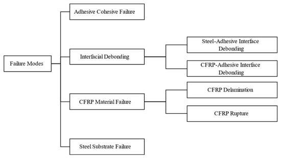
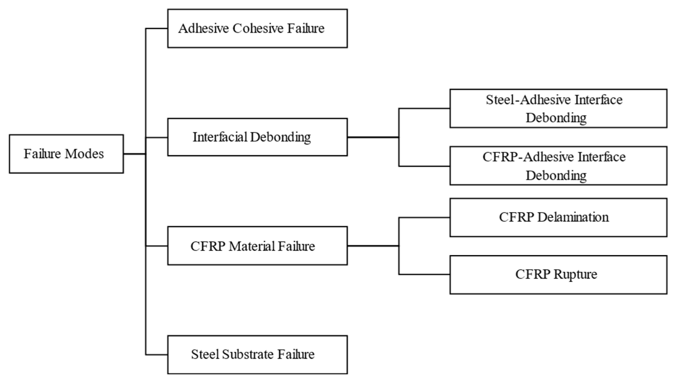
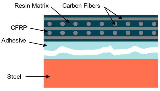
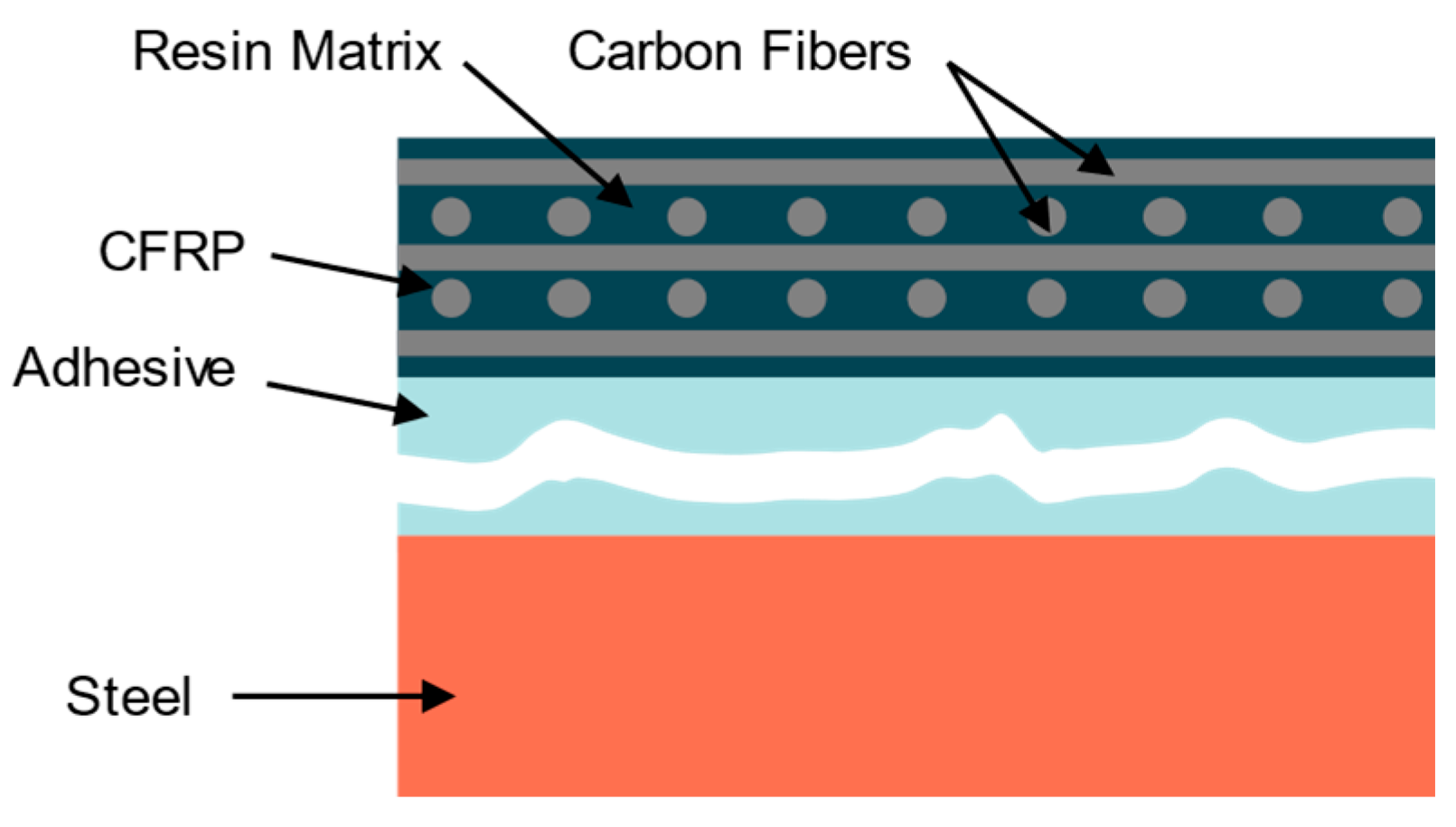
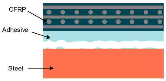
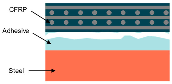
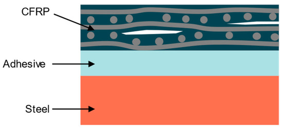
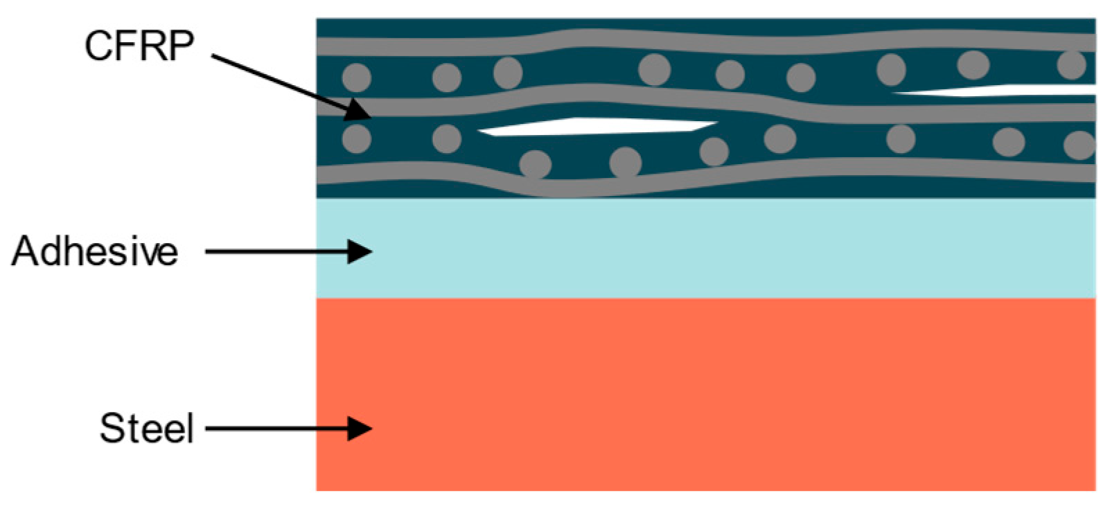
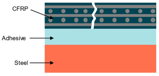
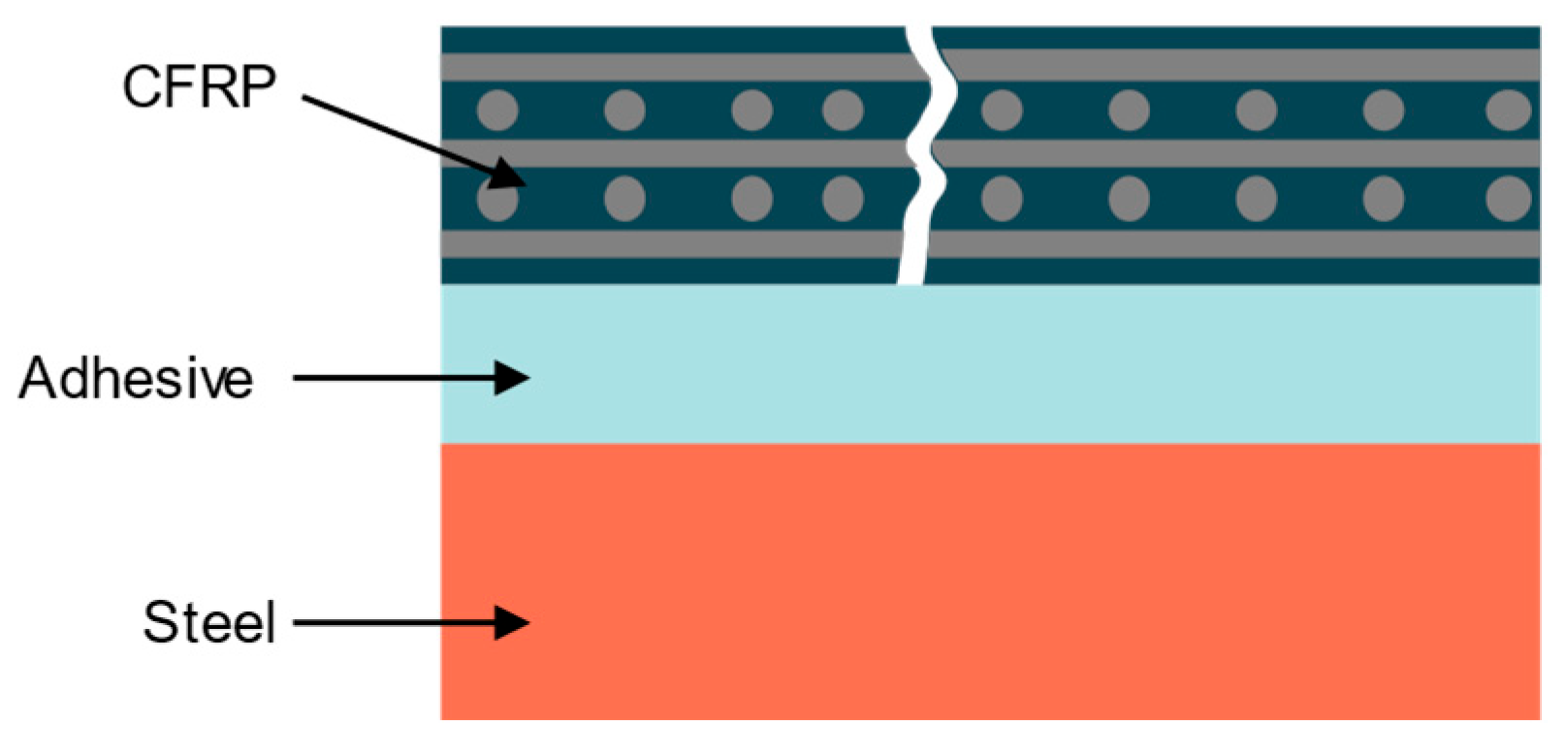
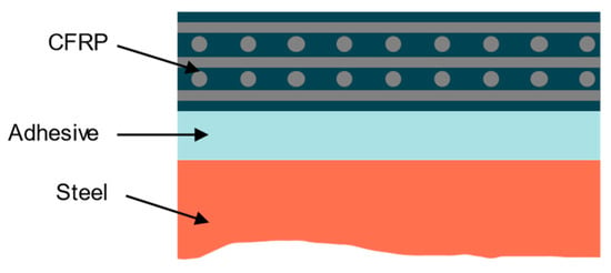
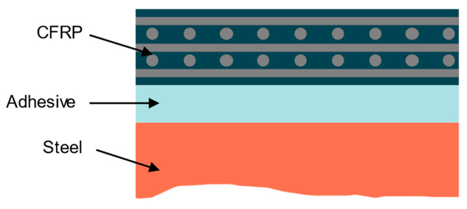
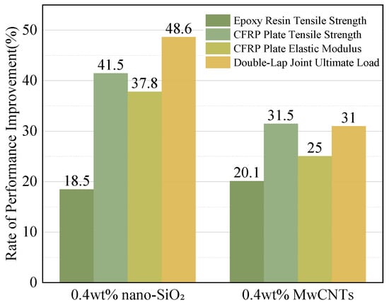
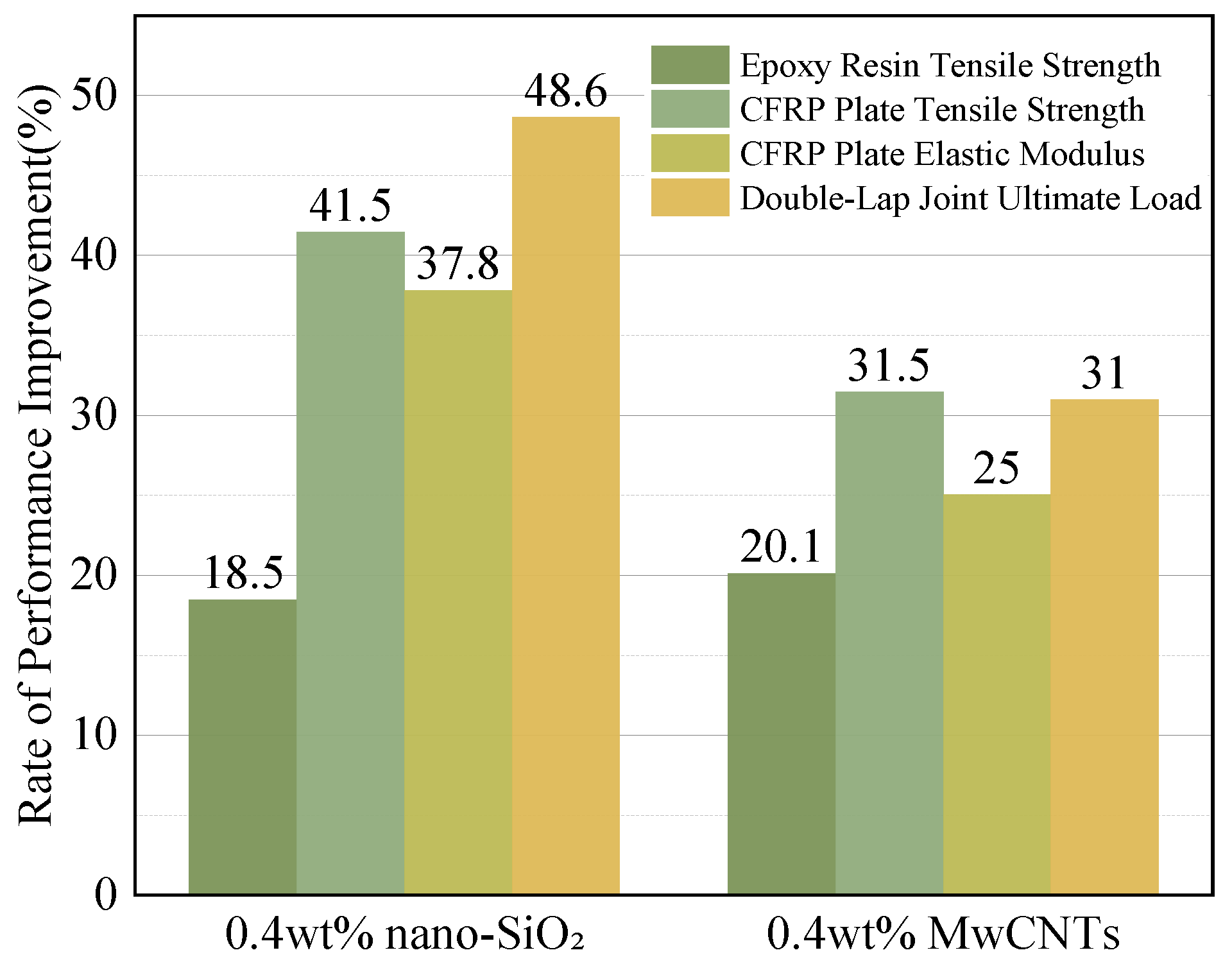
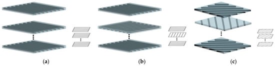
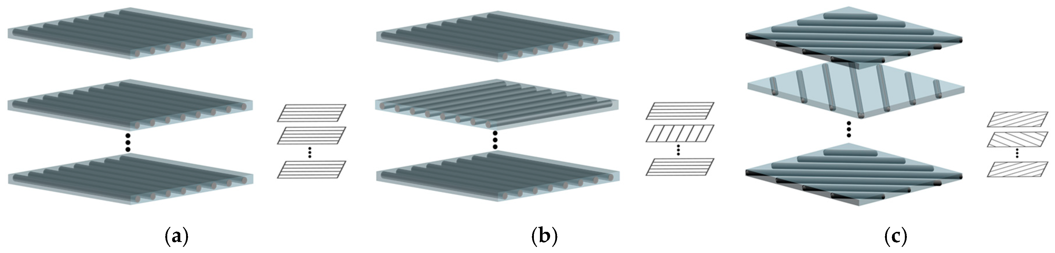
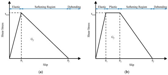
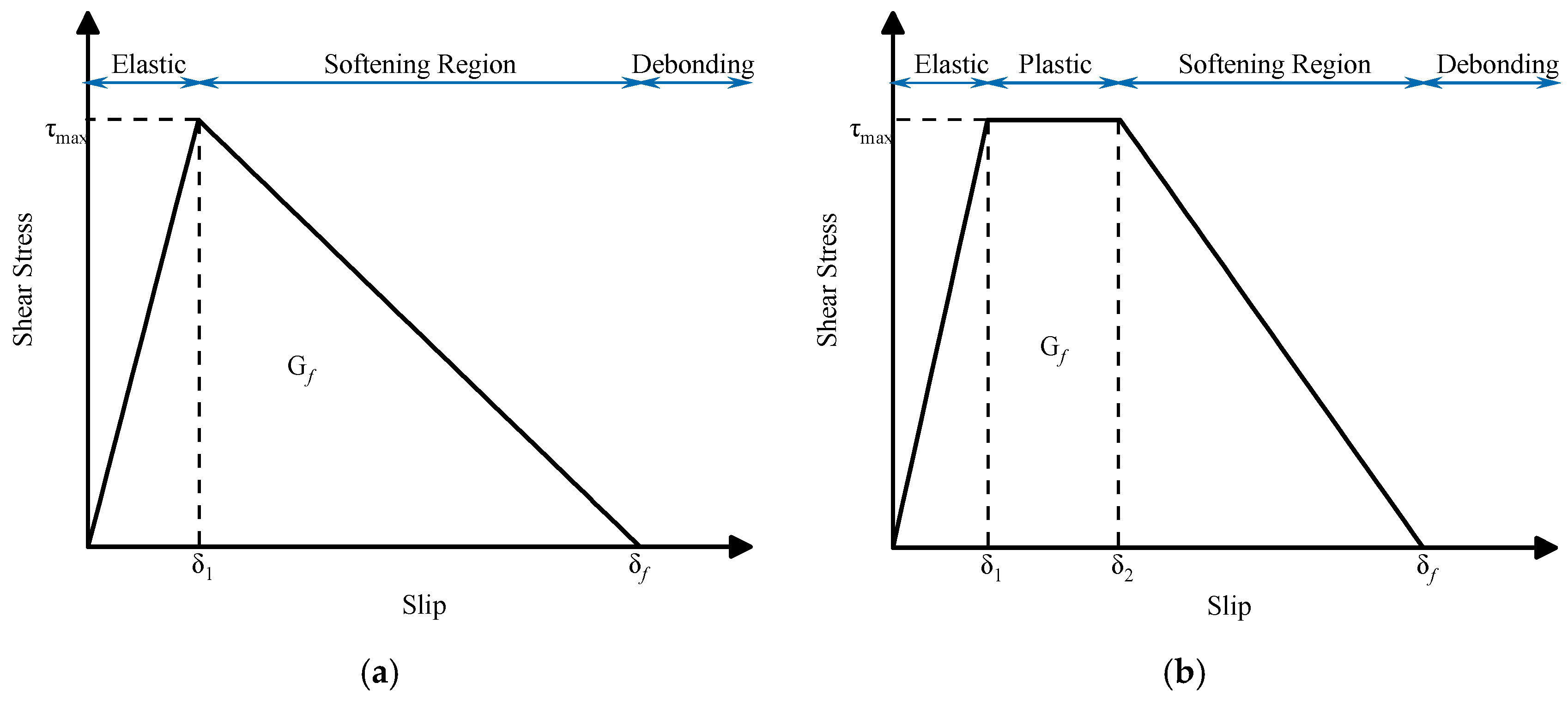
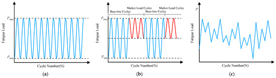
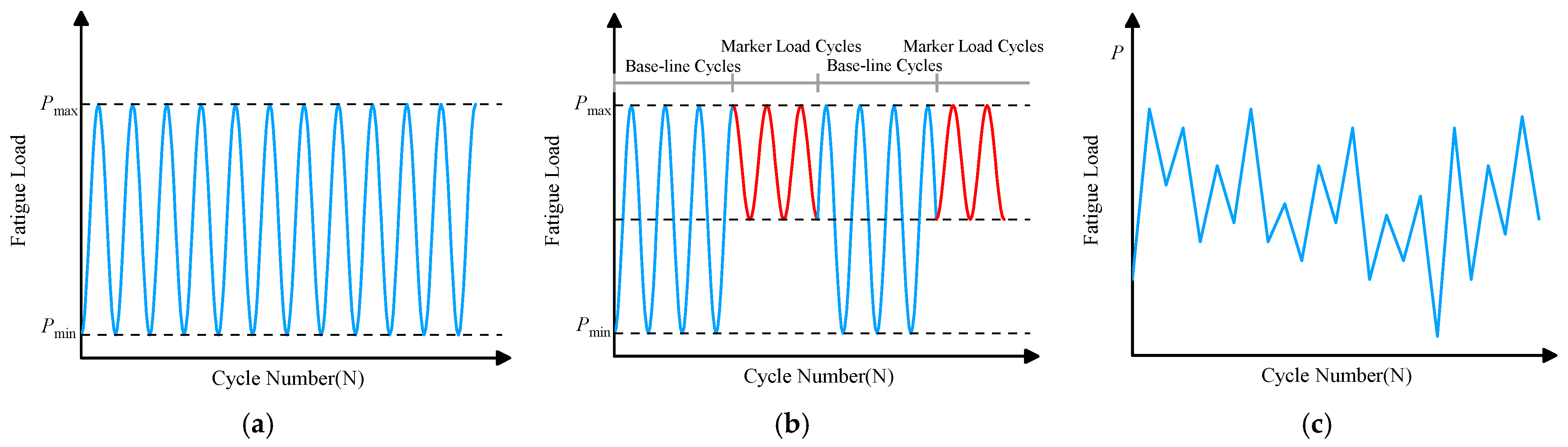
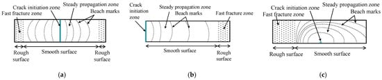
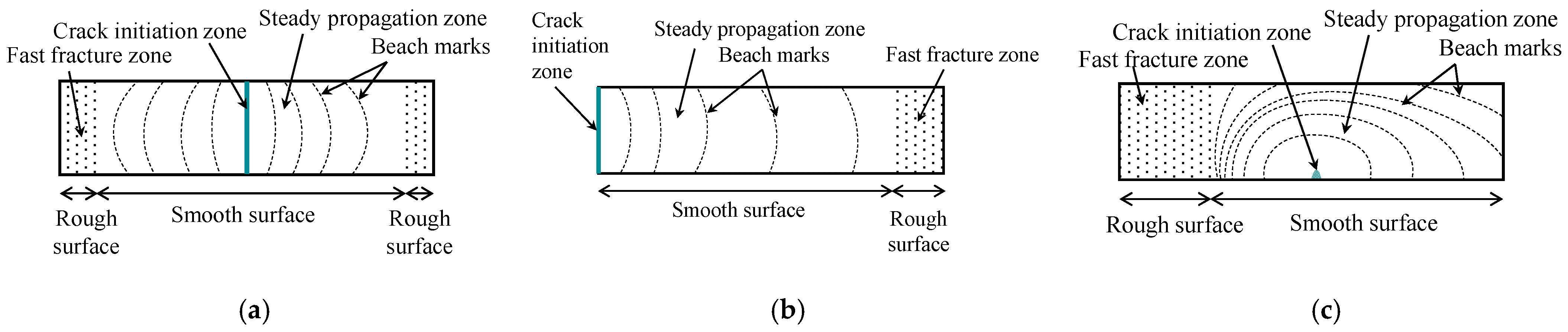












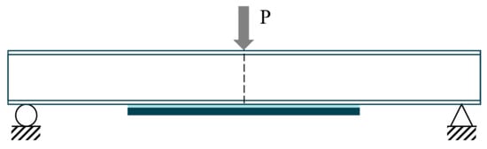
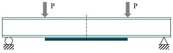
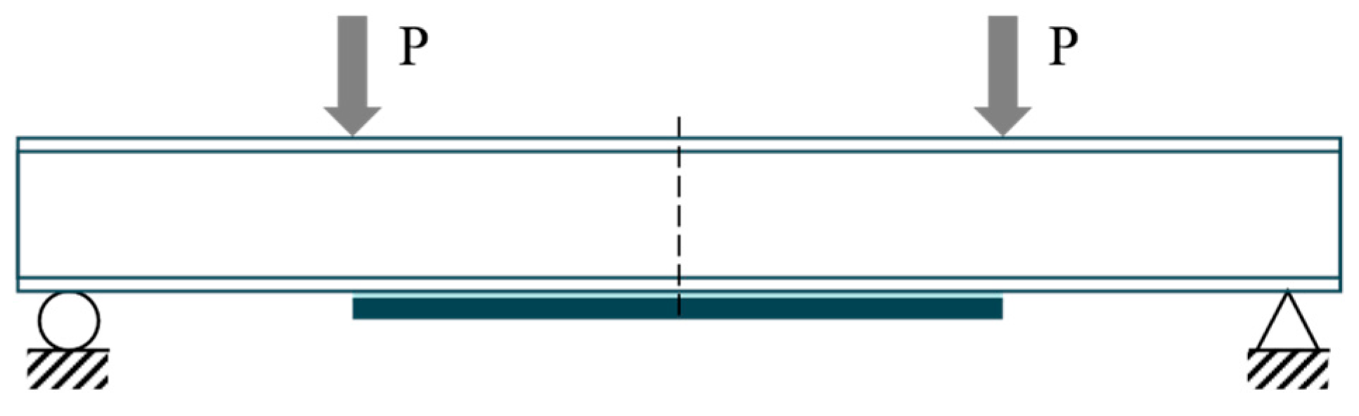
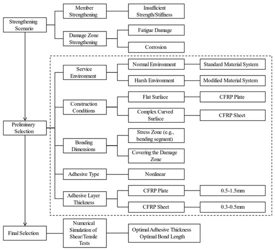
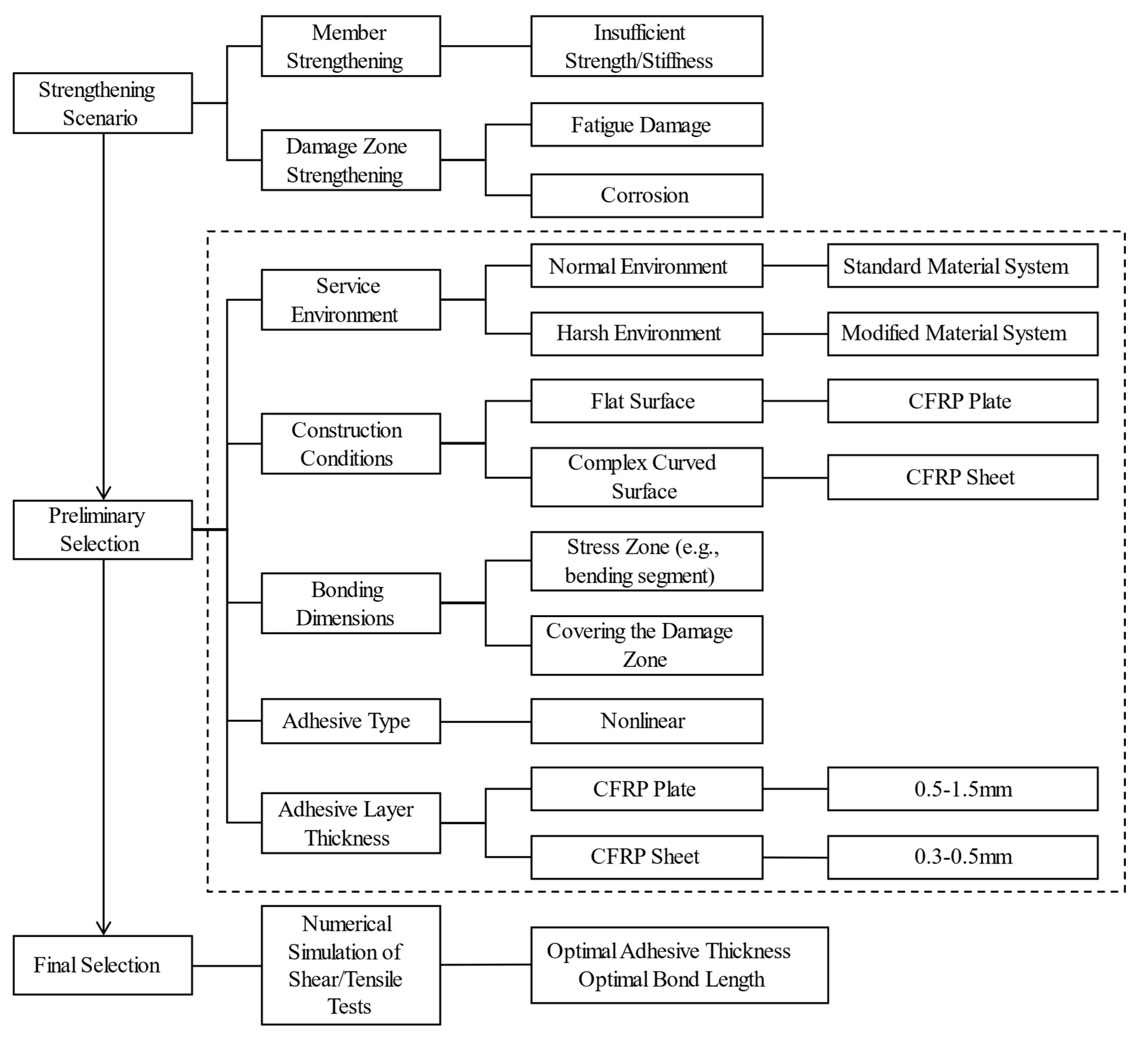

Disclaimer/Publisher’s Note: The statements, opinions and data contained in all publications are solely those of the individual author(s) and contributor(s) and not of MDPI and/or the editor(s). MDPI and/or the editor(s) disclaim responsibility for any injury to people or property resulting from any ideas, methods, instructions or products referred to in the content. |
© 2026 by the authors. Licensee MDPI, Basel, Switzerland. This article is an open access article distributed under the terms and conditions of the Creative Commons Attribution (CC BY) license.