


Abstract
Contact mechanics models are often inaccurate, due to (i) unknown contact radius, (ii) mechanical models not parameterizing it, (iii) in some models it is neither assumed meaningfully nor determined, and (iv) uncertain probe radius arising from manufacturer-specified nominal values and manufacturing tolerances. In this paper, an FEA model was used to quantify the evolution of the contact radius during indentation for two probe geometries: a pyramidal indenter (TRIANG2 nominal apex radius 2 nm) and a flat-ended punch (FLAT4000; nominal punch radius 4000 nm) on poly (vinyl chloride) (PVC), for which Young’s modulus (Eref) was obtained by a standard mechanical tensile method. The effective contact radius, , determined from FEA, was subsequently used in a Hertz-based force–indentation parametrization. Uncertainty in the probe apex radius due to manufacturer tolerances was addressed by SEM measurement of the conical tip, enabling assessment of its impact on the modulus estimated from AFM indentation. Based on these results, we propose a practical, geometry-aware analysis methodology that is transferable across probe geometries. The effective contact radius, , is first established using a well-characterized reference material and subsequently applied to a mechanical model to extract Young’s modulus. In this approach, the Hertz-based parametrization is used as a consistent mathematical framework, while the effective contact radius accounts for probe-dependent contact evolution.
1. Introduction
Mechanical properties are typically expressed as Young’s modulus, obtained by fitting a contact mechanics model to force–indentation curves, measured by an atomic force microscope (AFM) [1,2]. As the indentation increases, the contact radius between the AFM probe and the specimen grows [3,4,5]. Contact radius is inferred from the nominal tip geometry and the measured indentation depth [6]. The contact radius tends to be overestimated, leading to a systematic underestimation of the modulus [6]. This issue is rarely discussed, yet it has direct consequences for the comparability of mechanical data: different laboratories can obtain substantially different Young’s moduli for identical materials. Probe geometry is sometimes not known because of wear [7,8] and inaccuracies in the fabrication process. Scanning electron microscopy images of same-geometry cantilevers showed differences in tip radius of up to 30 times [7]. Also, manufacturers cannot ensure the exact geometry of the tip, which results to misleading mechanical properties. Therefore, evaluation of tip size by scanning electron microscope (SEM) is necessary to get reliable results [9]. While SEM can provide valuable information on probe geometry, it is not always practical or sufficient for routine AFM indentation experiments. Consequently, contact mechanics models are used to interpret force–indentation curves for Young’s modulus extraction, and it should account for uncertainty in the effective probe–sample contact geometry; however, in practice these models are not sufficiently equipped to do so, and this manuscript demonstrates this.
The Hertz contact model for spherical probes and Sneddon’s analytical extensions for pyramidal and flat probes are among the most widely implemented approaches in commercial AFM instruments [10]. Hertz’s model can also be used for conical or pyramidal tips where contact is dominated by apex rounding rather than the ideal cone geometry [11]. It assumes linear elasticity, frictionless contact, infinite sample thickness, and an idealized contact geometry [12,13].
Sneddon’s contact model is widely used for sharp probes; however, the formulation requires a single effective cone half-angle, whereas pyramidal probes are typically specified by multiple angles (for example face, edge, and side angles). Reducing these to one angle is not straightforward, and small differences in the chosen interpretation strongly affect the extracted modulus, making the fit sensitive to geometry handling rather than to the specimen response. In addition, Sneddon assumes a perfectly sharp indenter. The probe apex radius is not included, so the equations remain unchanged even if the real radius varies within manufacturer tolerances (in our case from 2 nm nominal up to 12 nm), despite clear changes in the force–indentation response and the extracted modulus. For polymers, this means that the analysis follows a model assumed contact geometry rather than verifying the true contact evolution during indentation, which is addressed in the present manuscript.
Some other analytical contact mechanics frameworks have been developed. For example, Briscoe et al. [14] discuss analytical solutions for several indenter geometries, including the cylinder, sphere, cone, Vickers pyramid, and Berkovich pyramid. Of these, only the spherical Hertz formulation contains an explicit tip radius R. Consequently, for conical and pyramidal models the governing equations do not change when the real apex radius varies, even though the force–indentation response does. As a result, changes in R cannot be captured, which compromises reliable Young’s modulus estimation.
Rico et al. [14] investigated living cells using pyramidal and spherical tips and reported that pyramidal indenters yielded Young’s modulus values about two times higher than those obtained with spherical indenters. This probe dependence indicates that a practical method is still needed to determine an effective Young’s modulus that remains consistent across different probe geometries.
In our previous research, experiments with the same material but different-geometry tips showed different results [6]. We determined the contact radius and Young’s modulus using AFM with two different probes: a sphere with a 20 nm radius (SPHERE20, Nanotools (Munchen, Germany) and a sphere with a 2 µm radius (SPHERE2000, sQube (Sofia, Bulgaria). The dependence of the contact radius on indentation was compared to the Hertz model. The results from FEA fit corrected contact radius values, which were smaller by 15.46% (SPHERE20) and 57.9% (SPHERE2000) than those calculated by the Hertz model. These geometry-dependent and misleading results raise questions about the limitations of the Hertz model. We consider the contact radius, an important parameter that is not defined directly in the Hertz framework, to be the key variable within the bundle of Hertzian assumptions, and therefore worth systematic investigation.
The aim of this work is to analyze how the effective contact radius evolves with indentation and how this evolution influences Young’s modulus values extracted from AFM force–indentation data. Two probe geometries are investigated, a flat-ended punch cantilever (FLAT4000, plateau radius 4 µm) and a sharp pyramidal tip (TRIANG2, nominal declared apex radius 2 nm). For TRIANG2, SEM measurements were performed to determine the real apex radius. Using FEA, we quantify how the force–indentation response changes when the pyramidal apex radius varies within the manufacturer-specified tolerance. We determined and compared Young’s modulus values—Enom, ESEM, Eeff and the ISO 527-2:1993 [15] tensile reference Eref—together with the associated contact radius assumptions nominal Rnom, SEM-detected RSEM, and effective contact radius Reff.
We offered an updated Hertz-based formulation in which the Reff is treated as an explicit variable rather than a fixed tip radius Rnom. This formulation was used in our suggested practical step-by-step workflow. Importantly, this Hertz-based formulation is broadly applicable across different cantilever tip geometries, including not only spherical probes but also sharp and flat-ended tips.
2. Rationale for the Study
Analytical indentation models are typically applied by assuming nominal probe geometry and fitting the resulting contact relation to force–indentation data to estimate Young’s modulus. However, not all models allow the relevant geometric parameters to be specified, which is a major limitation. Mechanical contact models assume that (i) the probe geometry is known with sufficient accuracy, which is not always the case, and (ii) the evolving contact is represented by the chosen analytical mathematical solution, which is not sufficient. We therefore define two systematic approaches corresponding to the two cantilevers (Table 1) used in this study: TRIANG2 (three-sided pyramid, nominal apex radius 2 nm) and FLAT4000 (flat-ended, nominal plateau radius 4000 nm). The FLAT4000 and TRIANG2 probes were intentionally selected as two limiting, non-idealized contact geometries to probe the limits of common contact mechanics assumptions and to test the role of the effective contact radius: for the same material, the two probes yield different Young’s moduli.
Table 1.
Characteristics of cantilevers.
2.1. Contact Analysis for the Pyramidal (TRIANG2) Probe
TRIANG2 was analyzed using the Hertz-based framework as a widely implemented base, augmented by a contact radius correction. In this approach, the effective contact radius is treated as a tunable parameter and adjusted such that the modulus estimated from AFM indentation using the Hertz-based model is consistent with an independent reference modulus. This retains the operational advantages of the Hertz-based workflow over the Sneddon model while explicitly addressing the missing determination of the contact.
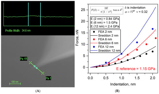
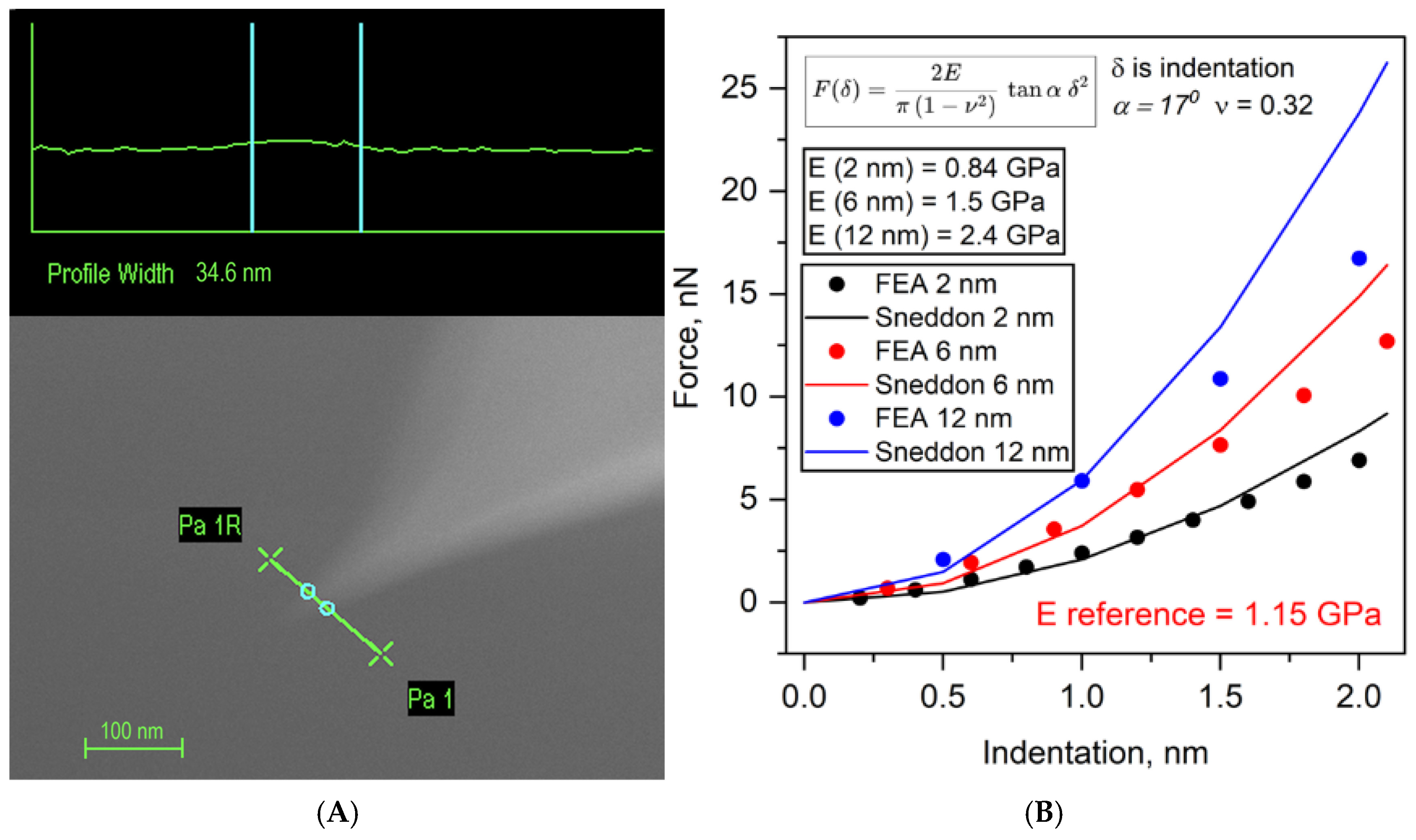
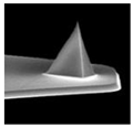
Real pyramidal tips are not perfectly sharp and exhibit finite apex rounding. A probe may be specified with a nominal apex radius of only a few nanometers, while the same datasheet allows substantially larger maximum radius values. SEM measurements (Figure 1A) revealed that the actual apex radius exceeded even the declared upper bound, and FEA shows that such deviations can strongly alter the force–indentation response and, consequently, the modulus estimate. Such rounding dominates the initial indentation regime, alters the contact mechanics, and thereby influences the measured force–indentation response, which is crucial for Young’s modulus determination. In contrast, the ideal Sneddon cone provides no mechanism to incorporate an apex (rounding) radius for conical or pyramidal tips, even though this radius measurably influences the force–indentation response (Figure 1B). Consequently, only the half-angle is specified, leading to systematic misestimation of Young’s modulus.
Figure 1.
(A). Scanning electron microscopy view of TRIANG2 cantilever tip. (B). Force–indentation curves simulated with FEA and compared with Sneddon model. Profile width is measured between points Pa 1 and Pa 1R.
Importantly, the objective here is not to quantify manufacturer tolerances or to correct nominal probe specifications. Instead, we focus on model-driven error mechanisms in commonly used contact analysis. For this aim we used FEA to quantify how the effective contact evolves relative to the contact inferred by the Hertz-based and Sneddon workflows. This focus motivates retaining a Hertz-based framework in our experiment as the baseline—even for conical cantilevers—because it provides a tractable route to contact radius determination, whereas the Sneddon formulation was not pursued for the same reason. Given its widespread implementation in commercial AFM software (NanoScope Analysis 1.50), we further enhance the Hertz-based approach by introducing a contact radius correction.
2.2. Contact Analysis for the Flat (FLAT4000) Probe
For the nominally flat probe, the indentation depths analyzed in this study were limited to δ ≤ 2 nm, which is several orders of magnitude smaller than the lateral dimensions of the probe plateau (8–12 µm). Under these ultra-shallow conditions, the macroscopic flat geometry does not govern the contact; instead, contact is controlled by local curvature arising from edge rounding, surface asperities, and/or slight probe tilt. Because the exact local contact geometry is not known a priori and evolves with indentation, no ideal analytical solution (spherical or flat-punch) can be strictly applied. Therefore, the Hertz-based contact model was retained as an effective evaluation framework for the force–indentation response, with the radius parameter interpreted as an effective-contact parameter rather than a geometric descriptor.
For the FLAT4000 probe, the nominal geometry is a flat punch; however, the contact surface is not perfectly planar. Due to fabrication tolerances and edge rounding, the probe exhibits finite curvature at the perimeter of the flat region; in addition, the effective contact can be affected by cantilever bending (shifting the probe position), imperfect flatness of the specimen and probe, and specimen surface roughness.
At small indentation depths, the contact is non-ideal and initiates within the curved edge region rather than across an ideal flat surface, as evidenced in our results. In this shallow indentation regime (δ ≤ 2 nm), the Hertz model is used as an effective parametrization of the force–indentation response, without implying ideal spherical contact. Nevertheless, as indentation increases, the real contact radius deviates strongly from Hertzian assumptions, introducing an increasing systematic bias in the contact radius.
For flat-ended probes, the Sneddon flat-punch solution is the conventional analytical starting point. This model assumes (i) a perfectly planar punch face and (ii) a constant contact radius that does not change with indentation. Both assumptions are difficult to satisfy experimentally. AFM indentation is not perfectly constrained under a purely vertical loading condition: the cantilever bends during loading, and the probe is commonly mounted with a finite tilt, which introduces non-ideal loading kinematics as indentation proceeds.
To mitigate edge sensitivity, we use a flat-ended geometry with a deliberately large perimeter curvature (large bending radius). Nevertheless, FEA shows that even under such conditions, effective contact does not remain constant and linear with indentation for the specimen. Instead, the contact evolves, and enforcing a constant-radius flat-punch solution produces systematic bias in the modulus. This motivates a revised flat-ended contact description that reflects indentation-dependent contact evolution rather than an ideal, constant-contact assumption.
This work aims to identify and reduce probe-dependent systematic errors in AFM-based modulus estimation that arise from contact misestimation. The key contributions are as follows:
- A probe-specific separation of sharp (TRIANG2) and flat-ended (FLAT4000) contact analysis to avoid conflating distinct error mechanisms.
- A sensitivity demonstration showing that Sneddon-based modulus estimates for TRIANG2 can vary substantially within realistic manufacturer-declared ranges of cantilever tip radius.
- An FEA assessment showing that the flat-punch constant-contact assumption is insufficient for FLAT4000 due to indentation-dependent nonlinear contact evolution and non-ideal kinematics of AFM cantilever–probe system.
By applying the same Hertz-based framework to both probes under identical specimens, any deviations in the extracted Young’s modulus arise primarily from geometry-dependent errors in the assumed contact radius. This strategy enables a systematic evaluation of the limitations of classical contact models.
3. Materials and Methods
3.1. Detection of Elastic Modulus by the Standard Method
The computer-controlled tension-compression test system Mecmesin MultiTest 2.5-I (Mecmesin Limited, Slinfold, UK), with a load sensor measurement error of 0.1%, was used for stress and strain measurements. The testing machine was controlled using the Emperor Force software v1.18-408 (Mecmesin Ltd., Slinfold, UK).
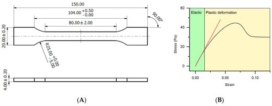
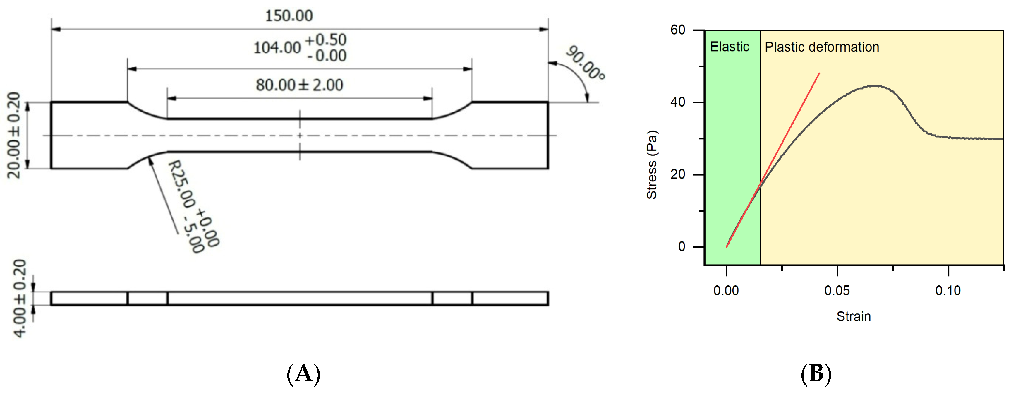
Transparent thermoplastic sheets of two different polymers were used: rigid poly (vinyl chloride) (PVC) and glycol-modified poly (ethylene terephthalate) (PETG). All sheets were obtained from Heliopolis (Vilnius, Lithuania). The PVC samples were of clear (non-plasticized) rigid grade, with high mechanical strength and chemical resistance. All sheets were used without additional coatings and were stored at ambient laboratory conditions (≈23 °C, relative humidity ≈ 50%) for at least 24 h before testing to allow equilibrium with ambient moisture. The samples were cut as shown in Figure 2.
Figure 2.
Specimen geometry and stress–strain response used for the determination of the elastic modulus Eref. (A) Geometry and dimensions of the tensile test specimen. (B) Stress–strain curve with indication of the elastic region used to determine the elastic modulus E.
Elastic modulus was calculated from the slope of stress–strain dependencies by ISO 527-2:1993 (Figure 2), and was fitted using the following equation [16]:
where Eref is the approximated modulus of elasticity, ε is the relative deformation, and n is the coefficient indicating the curve type (n = 1 corresponds to a linear curve consistent with Hooke’s Law, i.e., the conditional elastic limit for polymers). The specimens’ results were approximated specifically within this region.
σ = Eref · εn
3.2. Detection of Elastic Modulus by Atomic Force Microscopy
We used the BioScope II AFM and an optical microscope developed by Veeco Instruments Ltd. (Santa Barbara, CA, USA) to measure force–deflection curves. Spring constant calibration of the AFM cantilevers was performed using the thermal-noise (“Thermal Tune”) method with the Bruker BioScope II/NanoScope V system under ambient (air) conditions [17]. Force curves (n = 25 per sample) were recorded in ramp mode using a ramp size of 700 nm and a ramp frequency of 1 Hz.
Young’s modulus was calculated using Equation (2). We used two different cantilevers (Table 1) to evaluate the same material, PVC.
The Young’s modulus was calculated using the Hertz model as an effective fitting framework [18]:
where F is force, E is Young’s modulus, ν is Poisson’s ratio (0.32 for polymers), R is the radius of the tip, and δ is the indentation.
For non-spherical probes, the radius parameter in the Hertz-based equation is treated as an effective-contact parameter rather than as a physical probe radius. Throughout this work, Hertzian-based fitting is used as an effective parametrization of the force–indentation response rather than as a strict representation of ideal spherical contact.
For the corrected Hertz model, Reff determined from FEA was used instead of R.
Contact radius for TRIANG2 (Bruker (Billerica, MA, USA)) was calculated using the following equation [19]:
Sneddon’s cone model was used for additional determination of Young’s modulus:
where α is the cone half-angle.
For a rigid flat cylindrical punch of radius a indenting an elastic half-space:
For the nominally flat probe, the effective contact radius is smaller than the nominal flat-punch radius and evolves in nonlinear way with indentation depth; it does not represent a fully engaged flat-punch contact.
3.3. Modeling and Simulation
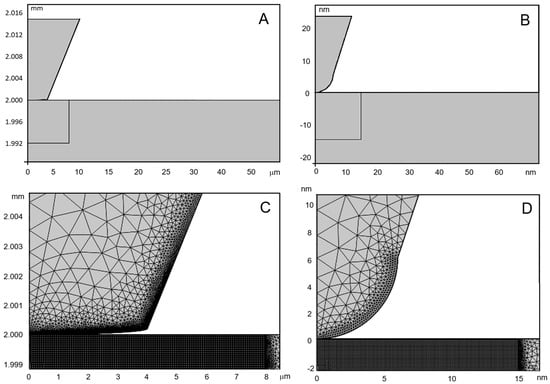
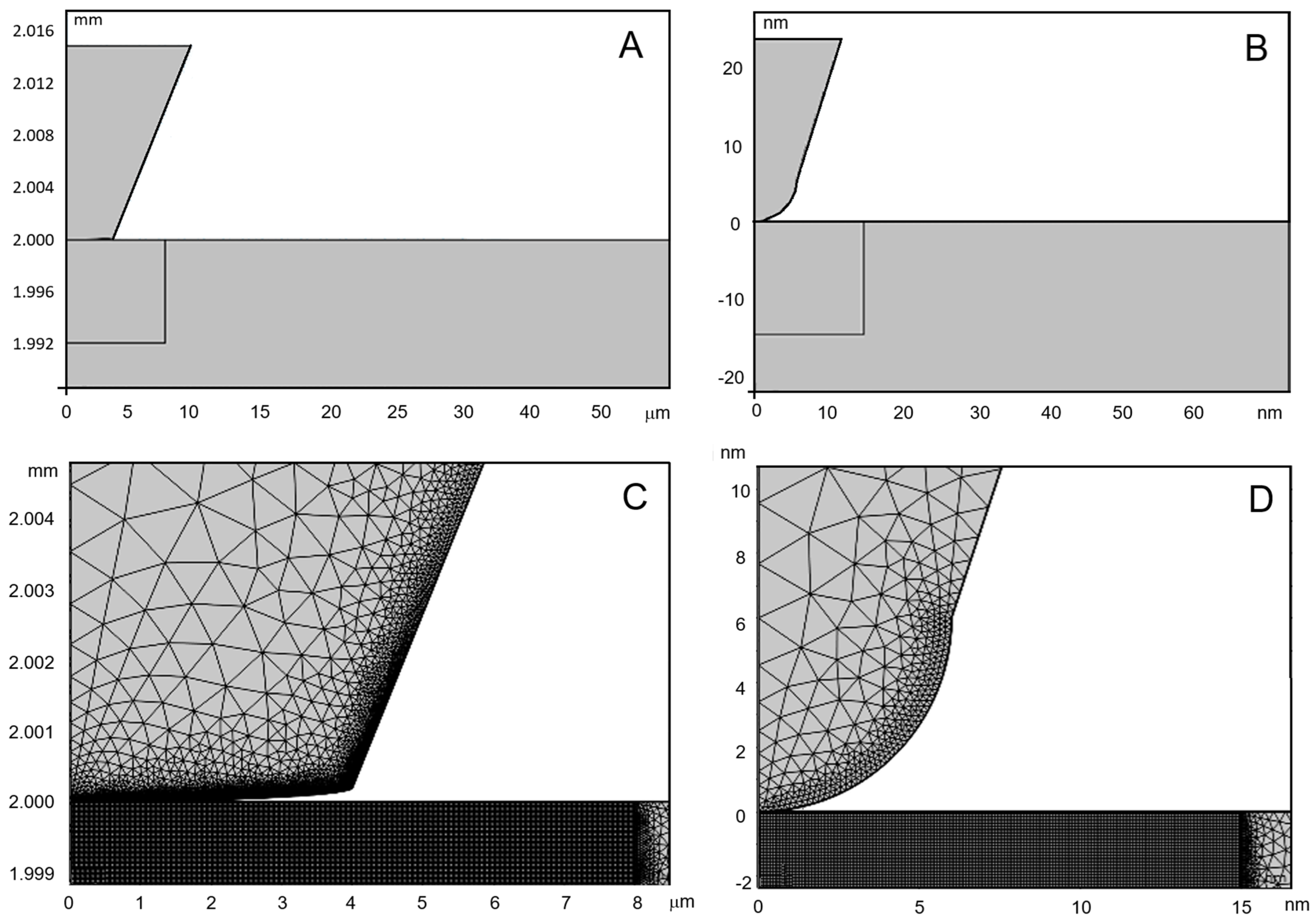
COMSOL Multiphysics 5.5 (Comsol AB, Stockholm, Sweden) was used to build finite element models of indentation by the FLAT4000 (Nanosensors (Neuchâtel, Switzerland)) and TRIANG2 probes. The validation process was performed on a single polymer (PVC) with an independently measured Young’s modulus by directly comparing the force–indentation curves from FEA and AFM experiments. Using a well-characterized reference material allowed us to isolate errors arising from model-inferred contact evolution without introducing additional material-dependent uncertainties; extension to other materials is therefore not required to test the central hypothesis of this work. A stationary axisymmetric setup was used (Figure 3). Both indenters were treated as rigid silicon-nitride bodies, and indentation was applied through a prescribed displacement in the z-direction. The PVC sheet was presented as a hyperelastic material with a Young’s modulus of 1.15 GPa and a Poisson ratio of 0.32. In order to show nonlinear effects in polymers, the St. Venant–Kirchhoff model was utilized [20]. Tip–sample interaction was implemented using a frictionless Augmented Lagrangian contact formulation, and the bottom surface was constrained so that vertical movement was fixed. Under the contact node, we use quasistatic stabilization with a stiffness multiplier of 1. To make the indenter’s contact domain smoother, we add a half-ellipse with a z-semiaxis of 200 nm to the tip of the FLAT4000 and a semicircle with a radius of 2 nm to the tip of the TRIANG2. (Figure 3A,B). The substrate thickness was 2 mm, with lateral dimensions large enough to avoid boundary effects.
Figure 3.
FEA model. Domain of the model zoomed around the indenter: (A). FLAT4000, (B). TRIANG2. Mesh distribution: (C). FLAT4000, (D). TRIANG2. Dashed line is symmetry line.
The geometry of each probe was represented according to its real shape: a flat-ended punch for FLAT4000 and a sharp pyramidal apex for TRIANG2. The tips were meshed with triangular elements. The PVC domain used quadrilateral elements beneath the indenter and triangular elements elsewhere. A refined mesh was applied in the contact region to improve numerical accuracy. The whole domain was meshed with triangles. Additionally, the PVC domain under the indenter was meshed with quads and refined by applying a node distribution of 200 × 200 for additional precision. In the contact region between the indenter and the PVC of FLAT4000, the element size of a quad was 26 nm, while the minimum size of a triangle was 10 nm. For TRIANG2, the element size of a quad was 0.075 nm, while the minimum size of a triangle was 0.18 nm. (Figure 3C,D).
The simulations yielded the contact radius, deformation field, and force–indentation curves for both geometries. These numerical results were compared with analytical contact models appropriate for flat and conical tips, and with AFM indentation data obtained using the same FLAT4000 and TRIANG2 probes. Matching tip geometry and indentation depths ensured consistent comparison between the simulated and experimental force–indentation behavior.
4. Results
4.1. Determination of Young’s Modulus by TRIANG2
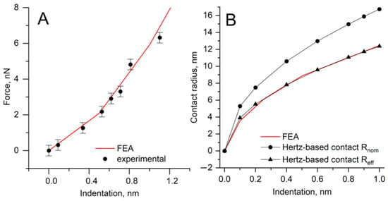
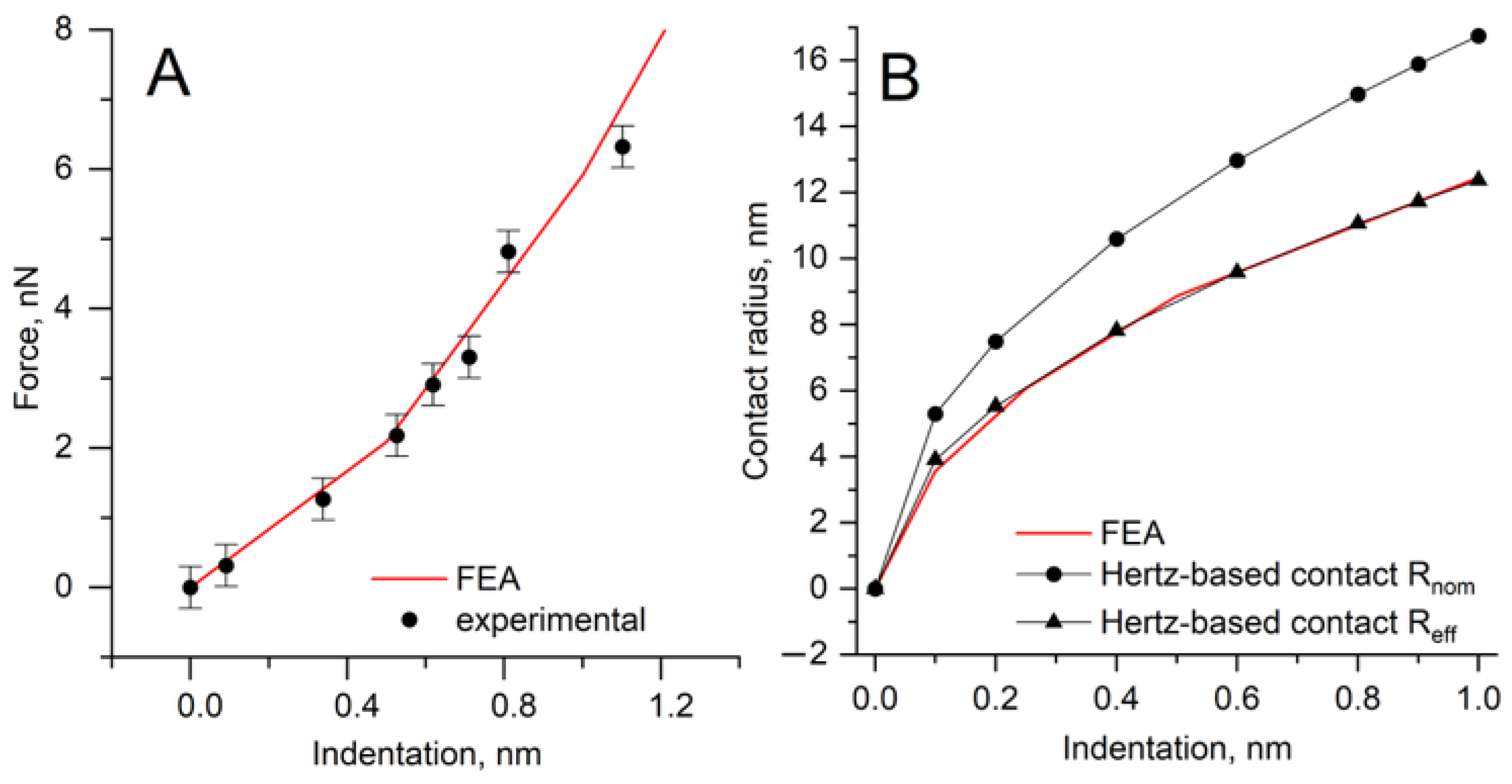
Finite element analysis (FEA) and AFM indentation measurements were compared in Figure 4. The experimentally measured force–indentation curves closely matched those obtained from the FEA simulations, validating the model framework. This agreement allows us to interrogate the contact mechanics that are not directly accessible in the mathematical contact models.
Figure 4.
(A). Force–indentation FEA model comparison with experimental data, with RSEM = 17.3 nm. (B). Contact radius–indentation nonlinear dependencies obtained from FEA, compared with the ones obtained using nominal geometry Rnom and contact parameter Reff.
Because the TRIANG2 probe is specified by the manufacturer as having a nominal radius Rnom of approximately 2 nm, but with a substantially larger permissible upper bound (up to 12 nm), we first performed scanning electron microscopy (SEM) to determine the actual probe geometry prior to interpreting force–indentation data (Table 2). It revealed a tip radius of RSEM = 17.3 nm, exceeding the manufacturer’s stated maximum. This discrepancy is critical because the assumed indenter geometry directly influences the force–indentation response and consequently the modulus.
Table 2.
Fitting parameters for TRIANG2 probe.
We then created an FEA model of TRIANG2 indentation on PVC, where the indenter radius was used as a fitting parameter. Iterative simulations demonstrated that RSEM = 17.3 nm reproduces the experimental force–indentation curve with the best agreement (Figure 4A). This provides an internal validation: (i) the SEM-determined radius is compatible with the mechanical response and (ii) the FEA framework can be used to extract quantities that cannot be measured directly in the experiment.
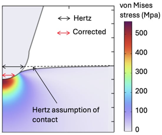
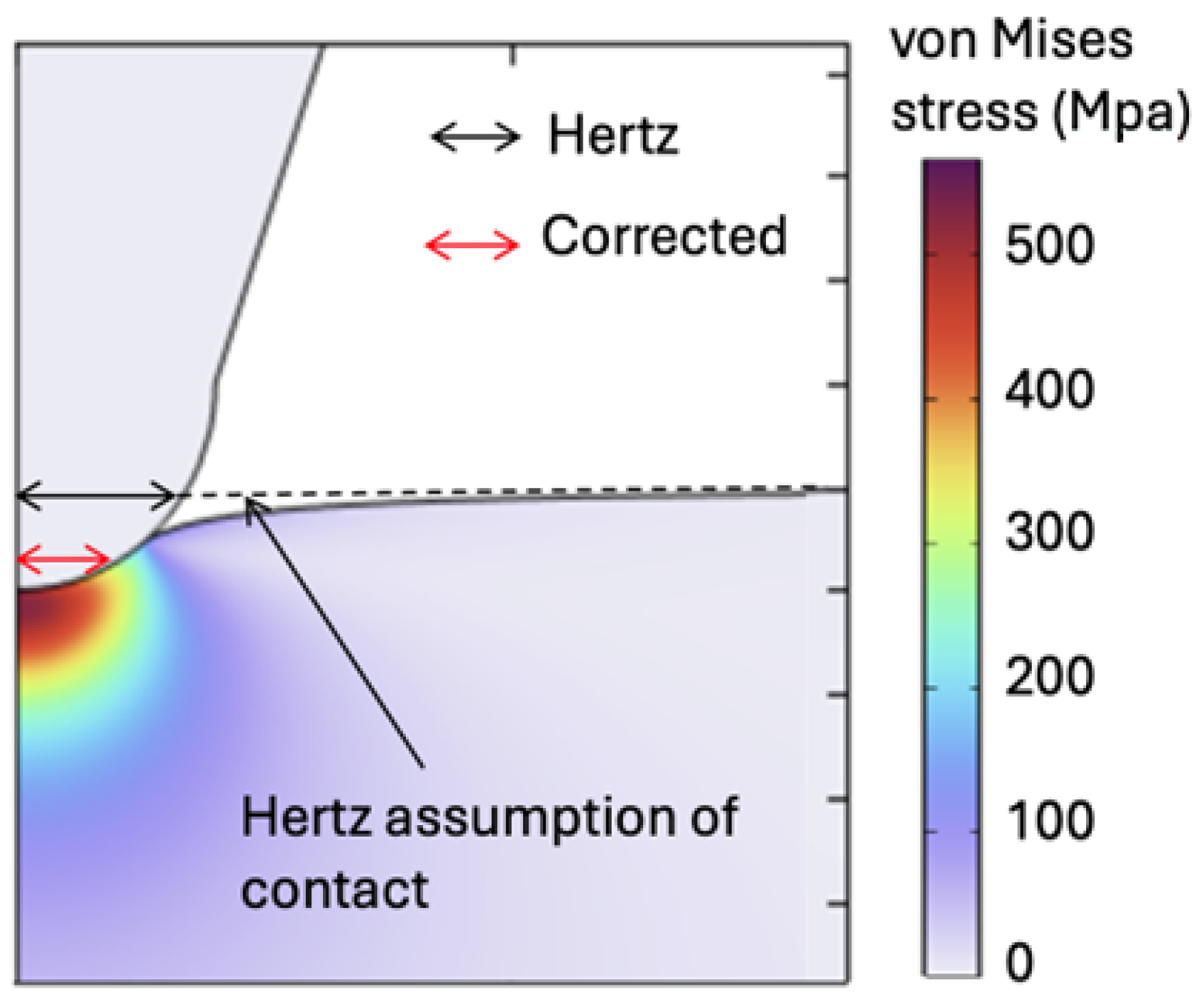
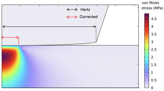
To clarify the origin of the probe-dependent deviations [6] in the modulus estimated from AFM indentation using the Hertz-based model, we analyzed contact evolution in terms of the effective contact radius inferred from FEA (Figure 4B). In the Hertz-based framework, the contact radius is not directly determined by the model; it is inferred from an idealized geometry and an ideal specimen deformation around the indenter, which implicitly assumes a self-similar contact growth. In contrast, FEA provides an evolving contact radius. The comparison between the Hertz-based contact radius estimation and the FEA-derived contact radius is shown in Figure 5.
Figure 5.
Visualization of contact radius: Hertz-based estimation vs. FEA.
SEM-based estimation of the apex radius (RSEM = 17.3 nm) was used to confirm that the fitting window ( nm) lies in the apex-dominated regime (), where the Hertz-based spherical approximation is applicable. Even when the correct tip radius from the SEM measurement is used, the Hertz model does not consistently reproduce the FEA contact evolution; depending on the probe–sample indentation depth, the Hertz-based contact formulation overestimates the effective contact radius. These results confirm that the contact description, not only the nominal tip radius, can dominate the modulus error. Consequently, should be interpreted as an effective-contact parameter rather than the physical apex radius.
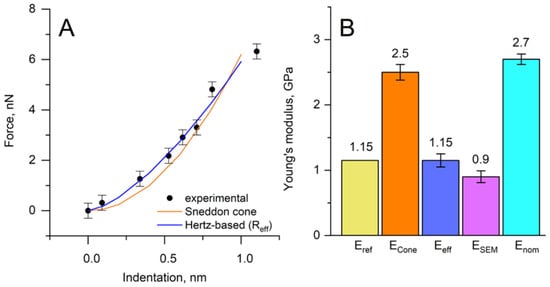
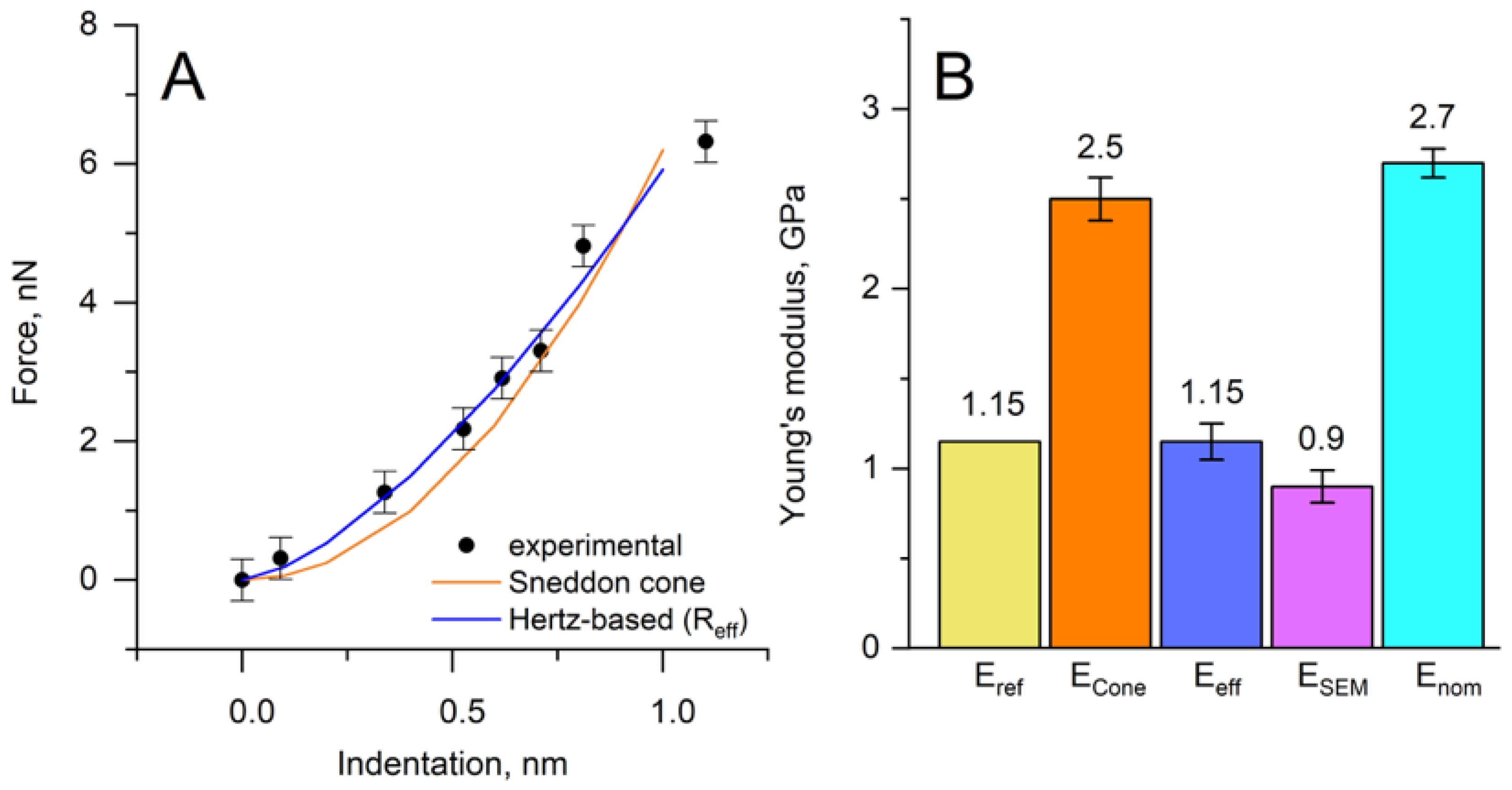
We next quantify how tip geometry uncertainty and contact inference propagate into modulus estimation. For PVC, we evaluated three Hertz-based analyses: (i) Enom, using the nominal manufacturer-declared value Rnom = 2 nm (representing the common case where the true geometry is unknown); (ii) ESEM, using the SEM measured radius RSEM = 17.3 nm; and (iii) Eeff, using contact parameter Reff. Only the contact-radius-aware evolution yields a Hertz model consistent with the PVC reference value (Eref = 1.15 GPa) (Figure 6). This demonstrates that supplying a nominal or even measured apex radius alone does not guarantee accurate modulus estimation by Hertz if the contact radius is evaluated using an idealized Hertz contact evolution.
Figure 6.
Experimental force vs. indentation curves and fitted models. (A). Hertz and Sneddon’s cone models fitted to TRIANG2 experimental data. (B). Reference Young’s modulus compared with that obtained from fitting.
For completeness, the same PVC dataset was also fitted with Sneddon’s conical model (Figure 6). Sneddon returned a markedly higher modulus (2.5 GPa; +217% relative to the reference), consistent with its strong sensitivity to geometric idealizations and lack of any parameter to incorporate the measured apex radius (SEM: 17.4 nm vs. 2 nm nominal). We nevertheless evaluated Sneddon because it is commonly provided as a standard analysis option in commercial AFM software. FEA further shows that realistic variations in tip radius produce large shifts in the force–indentation response (grafikas2355), which Sneddon cannot accommodate. In the context of the present work, this comparison motivates retaining the Hertz-based experimental framework as the baseline model, given its widespread implementation, while improving it through contact radius correction.
When the real probe geometry is unknown, and the contact radius is inferred from an idealized model, different laboratories obtain substantially different moduli for similar measurements [21,22]. Our results indicate two principal contributions to this variability: (i) insufficiently constrained probe geometry (as demonstrated by the SEM-measured radius exceeding the declared maximum) and (ii) the fact that the Hertz or other mathematical contact models are not able to determine the in situ contact radius.
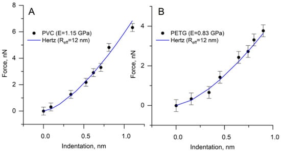
Finally, we tested the transferability of the contact radius correction by applying the FEA-derived effective-contact approach to PETG (Figure 7). Using the same TRIANG2 probe, the Hertz-based evaluation using the effective (corrected) contact radius yields a modulus that agrees with the PETG reference (0.83 GPa) (Figure 7B). This indicates that once a probe-specific effective-contact correction is established, differences in extracted modulus primarily reflect material properties rather than probe-dependent geometric artifacts. In subsequent work, we will extend the same workflow to a geometrically distinct and extreme indenter, FLAT4000, to assess generality across probe classes and to formulate a practical pre-measurement protocol that improves obtaining comparable, absolute mechanical-property values from AFM force spectroscopy.
Figure 7.
Force–indentation dependencies and fitted Hertz model with TRIANG2 probe. (A). PVC. (B). PETG.
4.2. Determination of Young’s Modulus by FLAT4000
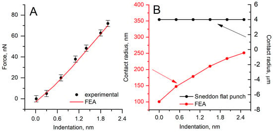
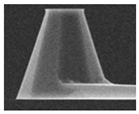
Unlike TRIANG2, where nanometric fabrication tolerances can produce large deviations from nominal geometry, the FLAT4000 indenter is manufactured on a micrometric scale with more controllable dimensions. Therefore, we did not perform SEM morphology for FLAT4000 and instead treated the nominal flat radius (4 μm) as fixed using the previously validated FEA framework to verify geometric consistency. FEA simulations using a 4 μm flat punch reproduced the experimental force–indentation curves for PVC, supporting that the assumed indenter geometry is compatible with the measured response (Figure 8A). FEA simulations show that the contact radius is nonlinear dependent on indentation, while Sneddon’s flat-punch model assumes that the contact radius is constant along the whole indentation range (Figure 8B). FEA shows the evolving contact radius between specimen and probe during the indentation in Figure 9.
Figure 8.
(A). Force–indentation curve fitted with FEA model. (B). Contact radius dependence on indentation.
Figure 9.
Visualization of contact radius: Hertz assumption vs. FEA.
The ideal Sneddon flat-punch model assumes a constant contact radius and perfectly planar contact. FEA show that for the nominally flat probe, the effective contact radius evolves with indentation due to edge curvature and non-ideal loading conditions; therefore, an uncorrected constant-radius Sneddon flat-punch model fit yields biased modulus values.
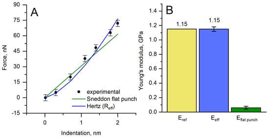
For the FLAT4000 probe, the force–indentation response appears nonlinear, especially in the beginning of the indentation (Figure 8A). The real probe–sample contact does not instantaneously engage the full nominal punch radius but develops in a nonlinear manner as indentation increases (Figure 8B). These results show that the Sneddon flat-punch assumption is not appropriate here: (i) it predicts an unrealistically constant contact behavior that is not observed in AFM measurements (Figure 9); (ii) this mismatch leads to a severe overestimation of the contact radius; and (iii) the inflated contact area produces a correspondingly large underestimation of Young’s modulus (Figure 10). Evolving contact introduces intrinsic nonlinearity into the force–indentation response; therefore, even if a segment appears approximately linear over a limited range, a flat-punch fit remains invalid.
Figure 10.
(A). Force dependencies on indentation with FLAT4000 probe. (B). Young’s modulus determined by fitting to experimental data.
We used the ideal Sneddon flat-punch model and benchmarked the results against the PVC reference modulus (1.15 GPa) (Figure 10). The Sneddon flat-punch fit yielded a substantially lower modulus (0.06 GPa), consistent with systematic contact radius overestimation with the constant-contact-radius assumption. To resolve this mismatch, we extracted an effective (corrected) contact radius from FEA and used it for the Hertz-based model. This approach is motivated by practical deviations from the ideal flat-punch assumptions, including non-ideal indenter and specimen flatness and probe tilt induced by cantilever bending, all of which cause the real contact to evolve during indentation (Figure 10A). Moreover, Figure 10A shows that the ideal Sneddon flat punch predicts an unrealistically linear force–indentation response that is inconsistent with the measured behavior and yields extremely low Young’s modulus values (Figure 10B) when applied to the small-indentation regime typical for AFM.
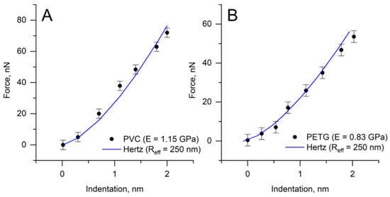
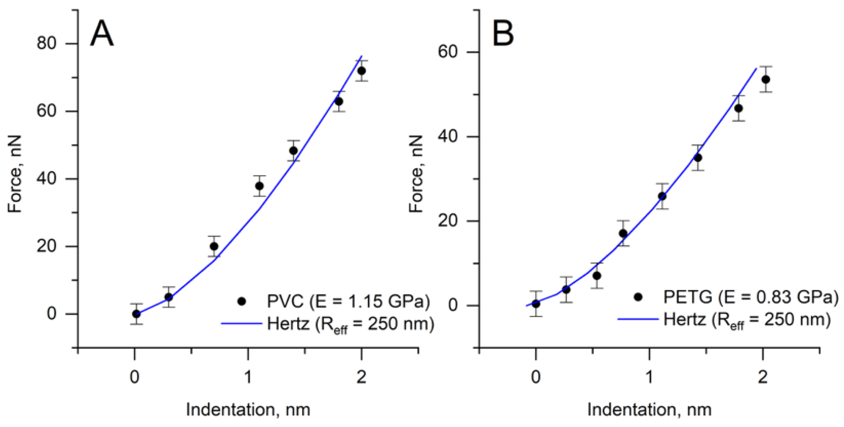
Accordingly, we retained Hertz-based as the baseline framework but replaced the nominal probe radius R with an effective contact Reff derived from FEA (Equation (8)). Using the extracted effective-contact parameter (Reff = 250 nm) in the modified Hertz-based model restored agreement with the PVC reference modulus, and applying the same correction to PETG likewise recovered the PETG modulus reference value (Figure 11A,B).
Figure 11.
Force–indentation dependencies and fitted Hertz model with FLAT4000 probe. (A). PVC. (B). PETG.
These results indicate that a contact radius modification of the Hertz-based framework provides a more reliable route to absolute modulus estimation for flat-ended indenters than the idealized Sneddon flat-punch model.
To solve contact radius misestimation problems for any kind of cantilever, we suggest practical advice methodology. First, the force–indentation curve should be measured on a material of known Young’s modulus. Then, fit the Hertz model to experimental data, extracting Reff. The next step is to measure the material of interest and fit the Hertz model using Reff. This can help to determine a more accurate Young’s modulus if an FEA model is not available.
5. Discussion
The results of this study demonstrate a systematic discrepancy between the mechanical properties obtained from AFM indentation analyzed using the Hertz-based model and those measured by the reference method. The primary source of Young’s modulus misestimation is the overestimation of contact radius, which is not evaluated enough in the Hertz model and is not included in Sneddon’s cone model. In the Hertz framework, the contact radius is not measured directly but is calculated from indentation depth and probe geometry, given by the manufacturers [23]. Although Sneddon’s flat-punch model includes a contact radius parameter, it assumes a constant contact from the onset of indentation; in AFM this assumption is generally invalid, leading to systematic underestimation of Young’s modulus.
Therefore, the Hertz-based model was retained as a practical baseline to construct a more reliable method for Young’s modulus estimation, with an updated contact radius formulation. The direct Hertz-based model leads to significant errors when applied to polymers and other soft materials [23,24,25]. When combined with the FEA-derived effective contact radius, the Hertz-based force–indentation analysis yielded Young’s modulus values consistent with independent references, effectively shifting the dominant sensitivity from nominal probe geometry to a calibrated contact radius parameter.
The results demonstrate that the contact radius inferred from classical contact mechanics relations deviates systematically from the contact radius obtained from approved FEA. This mismatch indicates that the real effective contact radius does not evolve according to the purely geometric assumption that it is determined only by tip geometry and indentation depth. Instead, the FEA reveals a distinctly nonlinear contact evolution that is highly sensitive to practical experimental factors, including the specimen’s deformation behavior, surface/probe flatness, probe geometry and manufacturing tolerances, and cantilever mechanics during indentation (bending, lateral probe shift associated with deflection). A mechanics-based interpretation is therefore essential, because purely theoretical approaches become intrinsically probe sensitive—as reported in the literature and confirmed in this manuscript. This sensitivity is problematic because it yields probe-dependent Young’s modulus estimates rather than an absolute material property, which is unacceptable when absolute values are required. Hertzian fitting is widely implemented in commercial AFM analysis software due to its numerical robustness; however, for non-spherical probes, the radius parameter in the Hertz-based equation should be interpreted as an effective-contact parameter rather than a physical probe radius. These findings extend our earlier study using spherical probes of different radii (20 nm and 2 μm), in which the Hertz model consistently overestimated the contact radius, with the deviation increasing for larger probe radii [6]. In that work, the consequence was a systematic underestimation of Young’s modulus for larger spherical indenters. In the present study, by employing extreme probe geometries—a flat punch and a sharp indenter—we demonstrate that the same fundamental limitation persists as with spherical contacts: the effective contact radius is not determined by the classical mechanical contact formulations itself and cannot be assumed to follow a purely geometric function of tip shape (flat, spherical or triangle), radius or half-angle and indentation depth. Instead, the real contact evolution is nonlinear and influenced by practical mechanical factors (specimen deformation behavior, surface flatness/roughness, probe tolerances, and cantilever bending and associated lateral probe shift, friction: probe–specimen), which makes classical, purely theoretical implementations probe-sensitive and can yield probe-dependent Young’s modulus estimates rather than absolute values.
At the same time, our results show that a Hertz-based model to interpret force–indentation characteristics can fit not only spherical but also flat-ended or sharp contacts when the spherical tip radius parameter R is reinterpreted as an effective contact radius Reff. This experimental computational parametrization based on FEA results indicates that the apparent “spherical-only” applicability of Hertz arises primarily from how the contact radius is defined and inferred. When the effective contact radius is defined appropriately (e.g., guided by FEA), the Hertz-based formulation yields Young’s modulus estimates consistent with absolute reference values across probe geometries, effectively challenging the common assumption that Hertz fitting is restricted to spherical indenters. We therefore view contact-radius-aware Hertz parametrization as a promising route for extending robust AFM mechanical-property estimation to more complex materials and probe types, reducing reliance on multiple alternative contact models that share a common weakness—insufficient determination of the effective contact radius [11,14,26].
Variations in real tip geometry (shape and radius) and contact radius–indentation dependencies can significantly influence the effective contact radius [9,27]. The present study demonstrates substantially larger discrepancies when extreme probe geometries are used. Compared to the predominantly moderate deviations reported in earlier polymer studies, the results obtained here emphasize that contact radius misestimation can become the dominant source of error for flat and sharp probes too. This comparison indicates that the limitations of Hertzian analysis extend beyond spherical contacts and that probe geometry must be treated as a critical parameter in AFM-based mechanical characterization of polymers.
For conical and pyramidal probes, FEA has been used to demonstrate that small uncertainties in cone angle or apex geometry can lead to substantial errors in the estimated contact radius and, consequently, in the fitted Young’s modulus [28,29]. In such cases, FEA-based contact radii are consistently smaller than those predicted by Hertz-type models, explaining the frequently reported overestimation of modulus for sharp tips. Similar conclusions have been reported for polymer thin films, where FEA revealed that a significant fraction of the measured indentation arises from deformation outside the nominal Hertzian contact zone [3]. This effect becomes more pronounced with increasing indentation depth, leading to depth-dependent modulus values when Hertz fitting is applied.
For flat-punch geometries, the benefit of FEA is even more pronounced. Unlike spherical or conical tips, flat-ended probes require an explicit definition of the contact radius, which is not provided by Hertz theory. Applying contact mechanics analysis to flat-punch indentation systematically underestimates Young’s modulus in soft polymers [3]. By directly resolving the contact boundary, FEA provides a physically consistent framework for interpreting force–indentation data obtained with flat probes. For the nominally flat probe, we suggest using the Hertz-based functional form as an effective fitting framework that compensates contact area misestimation due to nonlinear evolving contact.
Beyond correcting absolute modulus values, FEA also provides insight into how probe geometry influences the apparent mechanical response. FEA-based analysis reduces geometry-induced variability from tens of percent to below 10% once the real contact radius is considered [29,30,31]. This is consistent with the results of the present work, where FEA explains both the underestimation of Young’s modulus for the flat punch and the overestimation for the sharp probe by resolving the geometry-dependent nonlinear evolution of the contact radius.
6. Conclusions
Inaccuracies in the assumed contact radius dominate the modulus estimation, causing Young’s modulus to become probe-geometry-dependent rather than a true material property. The extreme contrast between the FLAT4000 and TRIANG2 geometries highlights that Young’s modulus estimates can become dominated by contact misestimation—either because the model does not account for the effective contact radius at all, or because its contact assumptions and “rules” are violated during indentation. Under these conditions, the Hertz-based and other classical contact models can strongly bias the final modulus estimate, yielding probe-dependent values rather than a true material property. Importantly, this limitation is not restricted to dramatically different probe designs: even nano-scale variations arising from manufacturing tolerances—often hidden when only nominal specifications are available and only revealed by SEM—can produce measurably different force–indentation responses for pyramidal (sharp) tips. More critically, even when the true apex radius is known, this parameter typically cannot be introduced explicitly into the most widely used sharp-indenter models implemented in common commercial AFM software. Instead, users are often limited to Sneddon-type formulations that rely on a highly sensitive half-angle parameter, which itself is difficult to determine reliably (requiring multi-angle characterization). Under these constraints, modulus estimation errors are effectively “built in.” Although alternative models exist, they largely share the same fundamental weakness: insufficient determination of the real effective contact.
This landscape of model choices and sensitivities motivated us to pursue a single, simple formulation applicable across probe types. We therefore adopted a Hertz-based framework, because it provides the most promising basis for generalization once the effective contact radius is treated as an essential, explicitly addressed parameter for reliable Young’s modulus determination. Crucially, we aimed to establish—and here we demonstrate—a practical workflow to minimize these contact-related errors, enabling absolute Young’s modulus values (when required) to be obtained consistently across different probes and multiple polymer materials. Correcting the contact radius, as demonstrated in the results, significantly improves Young’s modulus estimation accuracy.
Future research will include the application of new methodology for unknown materials, such as living cells, and finding a more universal method for the determination of the contact radius.
Author Contributions
Conceptualization, L.S. and I.M.; methodology, L.S. and R.S.; software, L.S., S.T., R.A. and N.K.; validation, L.S., R.A., N.K., E.B. and D.U.; formal analysis, L.S. and R.B.; investigation, L.S.; resources, E.B.; data curation, L.S., R.A. and N.K.; writing—original draft preparation, L.S., R.S., D.U., S.T., R.A., N.K., R.B., E.B., I.M. and A.R.; writing—review and editing, L.S., R.S., D.U., S.T., R.A., N.K., R.B., E.B., I.M. and A.R.; visualization, L.S., R.A. and N.K.; supervision, I.M. and A.R.; project administration, E.B.; funding acquisition, E.B. and I.M. All authors have read and agreed to the published version of the manuscript.
Funding
This research was funded by the Research Council of Lithuania (LMTLT), agreement No S-PD-24-136.
Data Availability Statement
The original contributions presented in this study are included in the article material. Further inquiries can be directed to the corresponding authors.
Acknowledgments
We thank Almira Ramanaviciene for accepting us into her laboratory at NanoTechnas—Center of Nanotechnology and Materials Science, Vilnius, Lithuania.
Conflicts of Interest
The authors declare no conflict of interest.
References
- Cappella, B.; Dietler, G. Force-Distance Curves by Atomic Force Microscopy. Surf. Sci. Rep. 1999, 34, 1–3, 5–104. [Google Scholar] [CrossRef] [Scilit]
- Morkvėnaitė-Vilkončienė, I.; Ramanavičienė, A.; Ramanavičius, A. Atomic Force Microscopy as a Tool for the Investigation of Living Cells. Medicina 2013, 49, 25. [Google Scholar] [CrossRef] [Scilit]
- Sakai, M.; Kawaguchi, S.; Hakiri, N. Contact-Area-Based FEA Study on Conical Indentation Problems for Elastoplastic and Viscoelastic-Plastic Bodies. J. Mater. Res. 2012, 27, 256–265. [Google Scholar] [CrossRef] [Scilit]
- Collin, J.-M.; Mauvoisin, G.; El Abdi, R. An Experimental Method to Determine the Contact Radius Changes during a Spherical Instrumented Indentation. Mech. Mater. 2008, 40, 401–406. [Google Scholar] [CrossRef] [Scilit]
- Paietta, R.C.; Campbell, S.E.; Ferguson, V.L. Influences of Spherical Tip Radius, Contact Depth, and Contact Area on Nanoindentation Properties of Bone. J. Biomech. 2011, 44, 285–290. [Google Scholar] [CrossRef] [Scilit]
- Striska, L.; Astrauskas, R.; Kozulinas, N.; Udris, D.; Tolvaisiene, S.; Macerauskas, E.; Morkvenaite, I.; Ramanavicius, A. Analysis of the Hertz Contact Model for Evaluating Mechanical Properties of Polymers Using the Finite Element Method. Polymers 2025, 17, 3018. [Google Scholar] [CrossRef] [Scilit]
- Morkvenaite-Vilkonciene, I.; Virzonis, D.; Dzedzickis, A.; Bucinskas, V.; Rozene, J.; Vilkoncius, R.; Vaiciulis, D.; Ramanaviciene, A.; Ramanavicius, A. The Improvement of the Accuracy of Electromagnetic Actuator Based Atomic Force Microscope Operating in Contact Mode and the Development of a New Methodology for the Estimation of Control Parameters and the Achievement of Superior Image Quality. Sens. Actuators A Phys. 2019, 287, 168–176. [Google Scholar] [CrossRef] [Scilit]
- Chung, K.-H. Wear Characteristics of Atomic Force Microscopy Tips: A Review. Int. J. Precis. Eng. Manuf. 2014, 15, 2219–2230. [Google Scholar] [CrossRef] [Scilit]
- Kulkarni, S.G.; Pérez-Domínguez, S.; Radmacher, M. Influence of Cantilever Tip Geometry and Contact Model on AFM Elasticity Measurement of Cells. J. Mol. Recognit. 2023, 36, e3018. [Google Scholar] [CrossRef] [Scilit]
- JPK Instruments AG Determining the Elastic Modulus of Biological Samples Using the Atomic Force Microscope. Available online: https://www.bruker.com/en/products-and-solutions/microscopes/bioafm/resource-library/determining-the-elastic-modulus-of-biological-samples-using-the-atomic-force-microscope.html (accessed on 2 November 2025).
- Butt, H.-J.; Cappella, B.; Kappl, M. Force Measurements with the Atomic Force Microscope: Technique, Interpretation and Applications. Surf. Sci. Rep. 2005, 59, 1–152. [Google Scholar] [CrossRef] [Scilit]
- Dimitriadis, E.K.; Horkay, F.; Maresca, J.; Kachar, B.; Chadwick, R.S. Determination of Elastic Moduli of Thin Layers of Soft Material Using the Atomic Force Microscope. Biophys. J. 2002, 82, 2798–2810. [Google Scholar] [CrossRef] [Scilit]
- Lin, D.C.; Shreiber, D.I.; Dimitriadis, E.K.; Horkay, F. Spherical Indentation of Soft Matter beyond the Hertzian Regime: Numerical and Experimental Validation of Hyperelastic Models. Biomech. Model. Mechanobiol. 2009, 8, 345–358. [Google Scholar] [CrossRef] [Scilit] [PubMed]
- Rico, F.; Roca-Cusachs, P.; Gavara, N.; Farré, R.; Rotger, M.; Navajas, D. Probing Mechanical Properties of Living Cells by Atomic Force Microscopy with Blunted Pyramidal Cantilever Tips. Phys. Rev. E 2005, 72, 021914. [Google Scholar] [CrossRef] [Scilit] [PubMed]
- ISO 527-2:1993; Plastics—Determination of Tensile Properties—Part 2: Test Conditions for Moulding and Extrusion Plastics. ISO: Geneva, Switzerland, 2003.
- Striška, L.; Vaičiulis, D.; Tolvaišienė, S.; Udris, D.; Kozulinas, N.; Astrauskas, R.; Ramanavičius, A.; Morkvėnaitė, I. 3D Printed Parts Exhibit Superior Elastic Properties to Milled Ones. Coatings 2025, 15, 963. [Google Scholar] [CrossRef] [Scilit]
- Bruker Corporation Determine Cantilever Spring Constant by Thermal Tune. Available online: https://www.nanophys.kth.se/nanolab/afm/icon/bruker-help/Content/Probe%20and%20Sample%20Guide/ThermalTune/ThermalTune.htm? (accessed on 19 September 2025).
- Bruker. NanoScope Analysis 1.50 User Manual; Bruker: Billerica, MA, USA, 2020. [Google Scholar]
- Ladjal, H.; Hanus, J.L.; Pillarisetti, A.; Keefer, C.; Ferreira, A.; Desai, J.P. Atomic Force Microscopy-Based Single-Cell Indentation: Experimentation and Finite Element Simulation. In 2009 IEEE/RSJ International Conference on Intelligent Robots and Systems, IROS 2009; IEEE: New York, NY, USA, 2009; pp. 1326–1332. [Google Scholar] [CrossRef] [Scilit]
- Dufrêne, Y.F. Atomic Force Microscopy of Fungal Cell Walls: An Update. Yeast 2010, 27, 465–471. [Google Scholar] [CrossRef] [Scilit]
- Touhami, A.; Nysten, B.; Dufrêne, Y.F. Nanoscale Mapping of the Elasticity of Microbial Cells by Atomic Force Microscopy. Langmuir 2003, 19, 4539–4543. [Google Scholar] [CrossRef] [Scilit]
- Kontomaris, S.V.; Stylianou, A.; Malamou, A. Is It Possible to Directly Determine the Radius of a Spherical Indenter Using Force Indentation Data on Soft Samples? Scanning 2022, 2022, 6463063. [Google Scholar] [CrossRef] [Scilit]
- Kontomaris, S.V.; Stylianou, A.; Chliveros, G.; Malamou, A. A New Elementary Method for Determining the Tip Radius and Young’s Modulus in AFM Spherical Indentations. Micromachines 2023, 14, 1716. [Google Scholar] [CrossRef] [Scilit]
- Holuigue, H.; Lorenc, E.; Chighizola, M.; Schulte, C.; Varinelli, L.; Deraco, M.; Guaglio, M.; Gariboldi, M.; Podestà, A. Force Sensing on Cells and Tissues by Atomic Force Microscopy. Sensors 2022, 22, 2197. [Google Scholar] [CrossRef] [Scilit]
- Oliver, W.C.; Pharr, G.M. Measurement of Hardness and Elastic Modulus by Instrumented Indentation: Advances in Understanding and Refinements to Methodology. J. Mater. Res. 2004, 19, 3–20. [Google Scholar] [CrossRef]
- Briscoe, B.J.; Sebastian, K.S.; Adams, M.J. The Effect of Indenter Geometry on the Elastic Response to Indentation. J. Phys. D Appl. Phys. 1994, 27, 1156. [Google Scholar] [CrossRef] [Scilit]
- Huang, S.; Tian, Y.; Wang, T. Experimental Investigation of Tip Wear of AFM Monocrystalline Silicon Probes. Sensors 2023, 23, 4084. [Google Scholar] [CrossRef] [Scilit]
- Nguyen, Q.D.; Chung, K.H. Effect of Tip Shape on Nanomechanical Properties Measurements Using AFM. Ultramicroscopy 2019, 202, 1–9. [Google Scholar] [CrossRef] [Scilit]
- Saito, I.; Sheridan, R.J.; Zauscher, S.; Brinson, L.C. Pushing AFM to the Boundaries: Interphase Mechanical Property Measurements near a Rigid Body. Macromolecules 2024, 58, 980–988. [Google Scholar] [CrossRef] [Scilit]
- Wang, Z.; Volinsky, A.A.; Gallant, N.D. Nanoindentation Study of Polydimethylsiloxane Elastic Modulus Using B Erkovich and Flat Punch Tips. J. Appl. Polym. Sci. 2015, 132, 41384. [Google Scholar] [CrossRef] [Scilit]
- Saringer, C.; Tkadletz, M.; Kratzer, M.; Cordill, M.J. Direct Determination of the Area Function for Nanoindentation Experiments. J. Mater. Res. 2021, 36, 2154–2165. [Google Scholar] [CrossRef] [Scilit]

Disclaimer/Publisher’s Note: The statements, opinions and data contained in all publications are solely those of the individual author(s) and contributor(s) and not of MDPI and/or the editor(s). MDPI and/or the editor(s) disclaim responsibility for any injury to people or property resulting from any ideas, methods, instructions or products referred to in the content. |
© 2026 by the authors. Licensee MDPI, Basel, Switzerland. This article is an open access article distributed under the terms and conditions of the Creative Commons Attribution (CC BY) license.