


Abstract
Although the arc-PVD Ti–Cr–Mo–Ni–N coatings deposited on HG20, HS123 and HV420 carbide alloys and C80W1 tool steel have approximately similar elemental and phase compositions, they differ in morphology, macrostructure, and macrostress level. The coating deposited on steel exhibits macrolayering, a wider coating–substrate transition zone and tensile structural macrostresses. In contrast, coatings deposited on carbide alloys develop compressive structural macrostresses. This behavior can be explained by the overheating during deposition caused by ion bombardment. Overheating is more pronounced for a coating on steel because the thermal diffusivity of steel is lower than that of hard alloys. The Ti–Cr–Mo–Ni–N coating on C80W1 steel exhibited a lower hardness (approximately 20.3 GPa) than the coatings on the carbide alloys (21.7–25.1 GPa). It also showed lower resistance to cohesive failure, with Lc3 ≈ 30 N, compared with ≈94 N for the coatings on the carbide alloys. Here, Lc3 denotes the critical load for cohesive cracking of the coating induced by plastic extrusion of the substrate material. The coating on steel also exhibited a higher specific wear rate at 20 °C and 500 °C. Its K20 and K500 values were 49.80 and 74.20, respectively. The corresponding values were 4.19 and 11.99 for HG20, 2.91 and 12.35 for HS123, and 6.33 and 14.71 for HV420, respectively, expressed in units of 10−6 mm3·N−1·m−1.
1. Introduction
Coatings based on Cr, Mo and Ti nitrides have favorable physico-mechanical properties, which ensure their relatively high wear resistance [1,2,3,4,5]. However, single-phase coatings of these systems have significant drawbacks that limit their application:
- The low heat resistance of titanium and molybdenum nitrides severely restricts their operating temperature ranges [6,7,8].
- The relatively low hardness of Cr–N-based coatings, combined with a high friction coefficient, promotes greater heat generation in the contact zone, thereby reducing the performance efficiency and service life of components [9].
- These coatings are characterized by a columnar structure. Oxygen rapidly diffuses along the boundaries of columnar crystallites towards the substrate surface, reducing the heat resistance of the coatings. Moreover, the columnar morphology is more conducive to crack propagation into the coating depth than an equiaxed (isomorphic) structure, thus reducing the adhesion strength of the substrate–coating composite [10,11,12].
The use of ternary Me–Me′–N systems significantly improves coating properties when the two metallic elements form mutually soluble nitrides with a face-centered cubic (FCC) lattice. For example, reference [6] demonstrated that ion-plasma vacuum-arc Ti–Cr–N coatings with chromium concentrations ranging from 10.1 to 25.2 at.% exhibit higher hardness than CrN coatings. At the same time, chromium-rich coatings show better wear resistance in aggressive environments. According to the findings in [13], alloying with chromium raises the oxidation resistance temperature of TiN coatings by over 100 °C. Another example of ternary coatings based on mutually soluble nitride phases is the Cr–Mo–N system. According to [14], the maximum molybdenum concentration at which a (Cr,Mo)N solid solution forms is 30.4 at.%; upon dissolution of molybdenum in chromium nitride, hardness increases due to solid-solution strengthening and an increase in residual macrostresses in the coating, reaching a maximum of 34 GPa at 21 at.% Mo. The system attracts considerable attention due to the excellent tribological properties of molybdenum nitride. Indeed, when a (Cr,Mo)N solid solution forms, the friction coefficient declines as the molybdenum fraction increases. For CrN/Mo2N multilayers, raising the temperature from ambient to 300 °C causes the friction coefficient to approximately double, a phenomenon attributed to the generation of hard wear debris, including CrN, Mo2N, and Cr2O3 particles. At 600 °C, however, the friction coefficient drops to 0.53, which is ascribed to the appearance of a Magnéli phase (MoO3) that provides solid-lubricant action. Moreover, these coatings exhibit a 300 °C improvement in thermal resistance relative to single-phase Mo2N coatings, thanks to the protective CrN layers that act as an oxidation barrier for molybdenum nitride. In some instances, the wear resistance of CrN/Mo2N coatings is six-fold greater than that of CrN and double that of Mo2N.
One effective alternative for enhancing surface functionality is to replace the TiN system with Ti–Mo–N. It has been shown [15] that it has a lower friction coefficient and wear rate than single-phase TiN. The increase in hardness is associated with the refinement of nitride grains—it is known that titanium and molybdenum nitrides are practically insoluble in each other [16]; accordingly, during coating deposition, competitive growth of TiN and Mo2N grains occurs, which blocks each other. Introducing into the system a nitride-forming metal that does not tend to form nitrides is one of the effective and well-known methods for synthesizing “superhard” coatings [17,18,19,20,21]. Such coatings include the ZrN–Ni(Cu), Cr2N–Ni, TiN–Ni(Cu) systems, etc. The presence of a metallic component in such systems leads not only to an increase in hardness due to the refinement of nitride grains down to several nanometers in size, but also to an increase in impact toughness. As the concentration of the metallic component increases, the columnar structure typical of nitride coatings becomes finer, up to the formation of an equiaxed structure—with a thin metallic or amorphous interlayer surrounding the nitride grains. This produces a dispersion-strengthened structure with a soft and ductile metallic matrix. In the Ti–N–Ni system, the hardness increases by more than a factor of two at 12 at.% Ni, with a grain size of 15–18 nm, compared with single-phase TiN coatings [22]. A significant synergistic effect in improving coating properties is observed for five-component coatings based on the Ti–Cr–Mo–Ni–N system. Thus, the study found a substantial increase in the wear resistance of coatings of this system on the nickel alloy ÉK61 and on silicon, compared with Ti–Cr–N and Ti–Cr–N–Ni coatings [23]. The study in Ref. [24] showed that Cr–Ti–Al–Mo–N coatings exhibited higher hardness (29.3 GPa) and better wear resistance (1.2 × 10⁻¹⁶ m3/(N·m)) than Cr–Ti–Mo–N, Ti–Mo–N and Cr–Ti–Al–N coatings. In [25], the authors, when investigating Al–Ti–N and Cr–Ti–Al–Mo–N coatings deposited by cathodic arc evaporation (CAE) on carbide alloy (WC–Co, 7 wt.% Co), found that at high hardness values (35.6 ± 1.5 GPa), the coatings of the first system had significantly lower H/E and H3/E2 ratios (0.059 and 0.124 GPa, respectively) than the coatings of the second system (0.071 and 0.157 GPa, respectively). These differences resulted in an almost three-fold increase in the wear resistance of the Cr–Ti–Al–Mo–N coatings compared with the Al–Ti–N coatings. The above indicates a considerable effectiveness of five-component coatings based on the Ti–Cr–Mo–N system with the addition of Ni and Al as strengthening elements under various friction conditions. When selecting strengthening coatings for different materials, the substrate must also be considered, as it can significantly affect the properties of both the coating and the coating–substrate system as a whole. The study in Ref. [26] showed that differences in macrostress among carbide alloy grades with different cobalt contents influence crack initiation and propagation. The effect of carbide alloy compositions on abrasive erosion resistance and on coating wear resistance was confirmed by the authors of [27,28]. This study aims to determine how carbide alloy grade and the use of tool steel as a substrate affect the structure and properties of Ti–Cr–Mo–Ni–N coatings.
2. Materials and Experiments
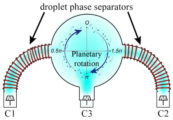
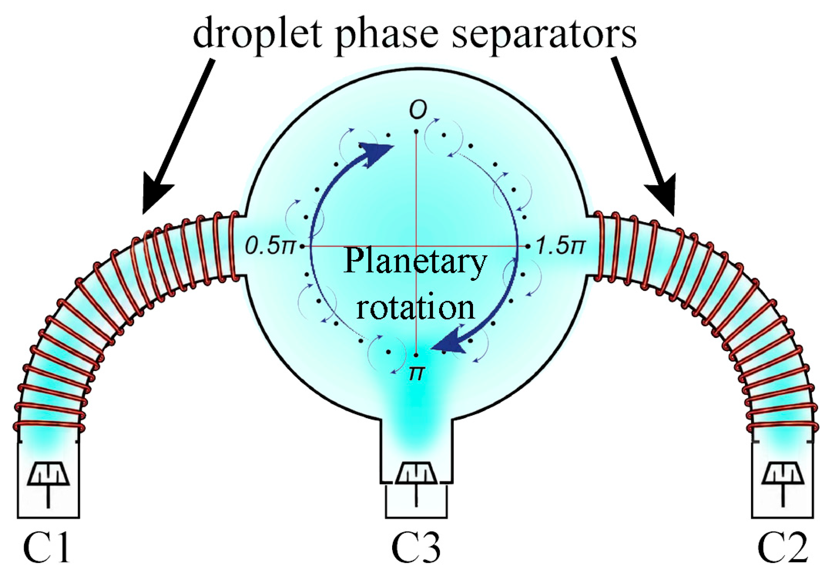
The Ti–Cr–Mo–Ni–N coatings were produced by ion-plasma vacuum-arc evaporation using a three-cathode system. The cathodes were prepared from a Ti–Ni alloy (50 at.%), Mo, and Cr, which were installed in evaporators C1, C2, and C3 (Figure 1), respectively (C1 and C2 are evaporable cathodes with droplet phase separators, while C3 is a direct-flow evaporable cathode).
Figure 1.
Schematic diagram of the ion-plasma vacuum-arc evaporation setup showing the evaporator configuration. C1 and C2 are cathodes with droplet separators; C3 is direct-flow evaporator.
The deposition times were 20 and 90 min. The deposited coatings had thicknesses on the order of ~1 μm and ~4 μm. The 20 min deposition was used to apply coatings to thin substrates employed for stress determination by the Stoney method. The ratio of coating thicknesses to substrate thicknesses was maintained in both processes. Nitrogen served as the reactive gas. The substrates were indirectly heated to 400 °C. The substrates revolved around the evaporating cathodes and rotated about their own axes. The rotation speed of the substrates during deposition was 1 rpm.
The reactive gas pressure PN2 was approximately 3 × 10⁻¹ Pa. The cathode current (Ia) was approximately 100 A for the Ti–Ni and Mo cathodes and approximately 90 A for the Cr cathode. The bias voltage applied to the substrates (Uc) was about 120 V. Prior to deposition, the substrate materials were ion-etched. Preliminary ion etching of the substrate surface was carried out for 10 min at a bias potential of 1 kV in magnitude. Deposition parameters for all substrates were selected to maximize the deposition rate while minimizing the droplet phase content in the coatings.
Three carbide alloy grades were selected as substrate materials: WC–Co (6 wt.%) (HG20); WC–TiC (15 wt.%)–Co (6 wt.%) (HS123); and WC–TiC (4 wt.%)–TaC (6 wt.%)–Co (8 wt.%) (HV420). These grades are the most widely used for tool and structural applications, together with carbon tool steel C80W1 (C: 0.81–0.89; Si: 0.17–0.33; Mn: 0.33–0.58; Ni: up to 0.25; S: up to 0.028; P: up to 0.03; Cr: up to 0.2; Cu: up to 0.25 wt.%), oil quenching from 780 to 800 °C, high-temperature tempering at ~650 °C, and hardness ~345 HV. The sizes of the substrates used for investigating physico-mechanical properties and determining macro stresses via the Stoney method were approximately 10 × 10 × 5 mm and 10 × 10 × 0.4 mm, respectively. Substrate roughness was ~0.2 µm.
Morphological features were assessed using a Vega 3SB scanning electron microscope (Tescan, Brno, Czech Republic) equipped with an X-ACT SDD energy-dispersive X-ray spectrometer (Oxford Instruments, Abingdon, UK). Microstructure was examined with a JEM-2100 transmission electron microscope (JEOL, Akishima, Tokyo, Japan) operating in microdiffraction mode, which provided electron diffraction patterns for phase identification. For this purpose, lamellae were prepared from the coatings by ion thinning. Chemical states and elemental compositions were determined by X-ray photoelectron spectroscopy on a Versa Probe II spectrometer (Physical Electronics, Chanhassen, MN, USA). Ion etching of the sample surface during depth profiling by XPS was performed with Ar+ ions at an ion energy of 2 keV and a raster of 2 × 2 mm2, which corresponds to an etching rate of 13 nm/min for SiO2. Phase composition was further verified by X-ray diffraction on an Ultima IV diffractometer (Rigaku Corporation, Akishima, Tokyo, Japan) with Cu Kα radiation and a graphite monochromator, using an asymmetric scanning geometry (5° incidence angle). Coherent scattering domain sizes (D), lattice microstrains (ε), and the complex nitride lattice parameter were calculated from (111) and (222) reflections recorded in symmetric geometry. Physical peak broadening was extracted by jointly fitting the specimen against a reference germanium powder (10–20 µm) using pseudo-Voigt functions.
Hardness and elastic modulus were evaluated by instrumented indentation using the Oliver–Pharr method [29] and a Micro-Hardness Tester (CSM Instruments, Peseux, Switzerland) at a load of 25 mN. The reported E values are interpreted as effective indentation moduli of the coating–substrate systems rather than intrinsic elastic moduli of the coatings. The indentation depth did not exceed 10% of the coating thickness (ISO/CD 14577); however, this criterion does not eliminate the substrate contribution to the measured elastic response. Accordingly, H/E and H3/E2 [30] were calculated using the measured effective modulus and are considered comparative indices of the tested coating–substrate systems.
Tribological properties were studied with a Tribometer (Nanovea, Irvine, CA, USA) in a pin-on-disk configuration at 20 °C and 500 °C in air. The counterbody was an alumina ball; the normal load was 5 N, sliding speed 10 cm/s, sliding distance about 60 m, and track radius 3 mm. The wear tracks and their edges were cleaned of loose wear debris using compressed air and a soft brush. Wear rates were measured using a chromatic confocal optical head ENDO 0.1 DROIT (STIL Marposs, Brétigny-sur-Orge, France). The measurement error is no less than 0.05 µm.
Coating adhesion and cohesive strength were evaluated by progressive-load scratch testing up to 100 N on a Revetest instrument (CSM Instruments, Peseux, Switzerland). Acoustic emission, tangential force, and friction coefficient were recorded to determine critical loads Lc1, Lc2, and Lc3 corresponding to first cracking, adhesive delamination, and the critical load for cohesive cracking of the coating induced by plastic extrusion of the substrate material; local substrate exposure may occur as a consequence but is not the defining feature of the cohesive mechanism, respectively [31]. Failure morphology was examined by optical microscopy.
Macrostresses arising from differential thermal expansion and structural inhomogeneities were calculated using the Stoney equation [32,33,34]. Substrate curvature radii before and after deposition were measured with an optical profilometer WYKO NT1100 (Veeco, Plainview, NY, USA). Layer thicknesses were determined from cross-sectional SEM images. The curvature radius was computed as
where L is the specimen length and b is the deflection (sagitta).
To determine the macrostress values in the coatings, special thin substrates made of hard alloys and tool steel with thickness ts were prepared, onto which Ti–Cr–Mo–Ni–N coatings with thickness tf were deposited. The ratio of the coating thickness to the substrate thickness was of the same order as for the samples prepared for studying the physico-mechanical, tribological, and adhesion properties, in which the coating thickness was 4 ± 0.1 μm.
3. Results and Discussion
3.1. Structure and Substructure Characteristics, Elemental and Phase Compositions of Coatings Deposited on Carbide Alloys and Tool Steel Substrates
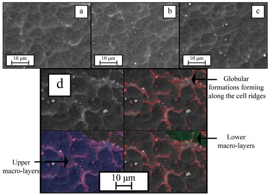
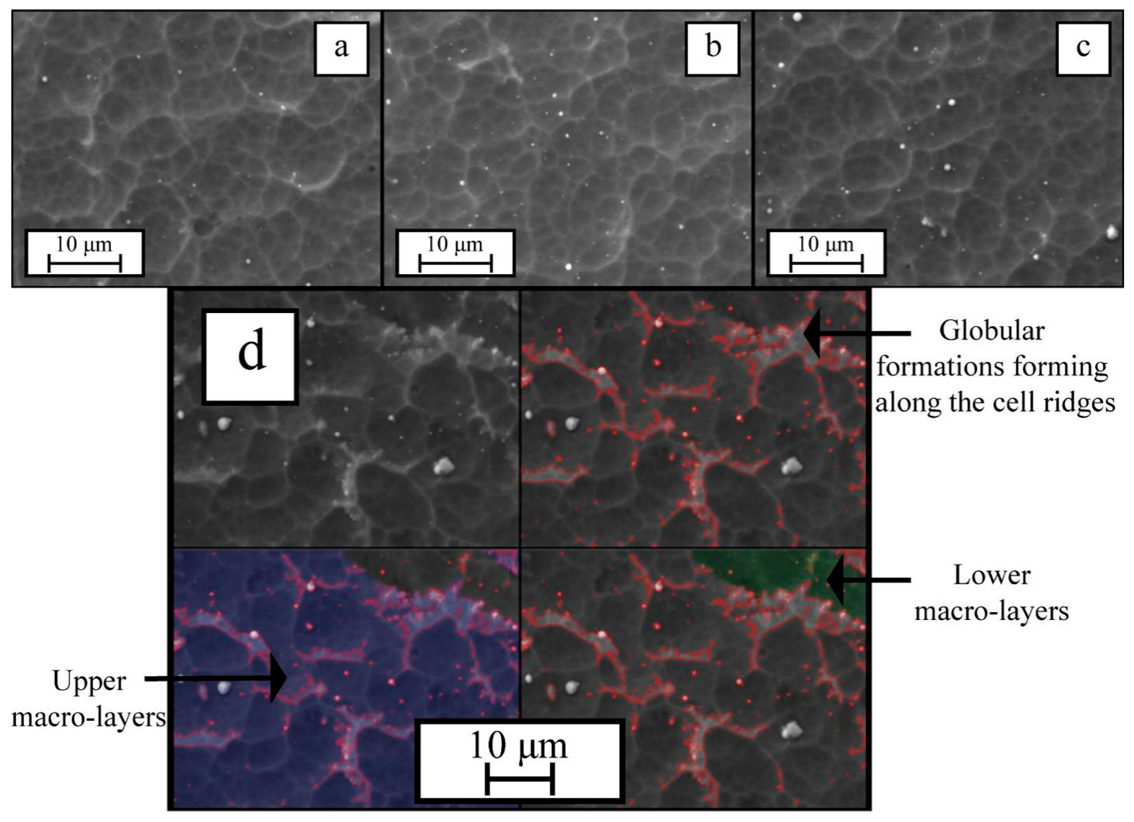
Figure 2 presents Ti–Cr–Mo–Ni–N coating micrographs grown on various substrate compositions.
Figure 2.
Ti–Cr–Mo–Ni–N coating morphology on various tool materials: (a) HG20; (b) HS123; (c) HV420; (d) C80W1.
Morphological analysis shows that the coatings deposited on carbide alloy and steel substrates have a reticulated surface texture consisting of numerous cells. This texture results from replication of the substrate roughness produced by sandblasting before deposition. On steel substrates (Figure 2d), however, globular formations appear along cell ridges, which can be explained by steel’s much lower thermal diffusivity (13 m2·s−1·106) versus that of carbide alloy substrates (32, 23, and 19 m2·s−1·106 for HG20, HS123, and HV420, respectively) [35,36,37,38]. This leads to a lower cooling rate for the growing coating on steel and thus a possible vapor–liquid–solid phase transition, whereas on carbide alloy substrates coating formation proceeds via a vapor–solid transition. Globule formation along the cell ridges is determined by less efficient heat removal from these regions than from the cell sidewalls. Additionally, step-like surface areas appear on steel substrates, indicating a macro-layered coating structure. This may be due to tensile macrostresses of different nature arising in the coating, which at a certain stage of growth lead to rupture of the growing coating layer. This rupture exposes fresh surface where new coating phase nuclei form and grow, producing a new layer. An analysis of macrostresses in the substrate–coating composite, with confirmation of this hypothesis, will be carried out below.
Table 1 presents EDX chemical composition data for the Ti–Cr–Mo–Ni–N coatings. The results indicate that, within the experimental error, the elemental composition of the coatings is essentially independent of the substrate.
Table 1.
Ti–Cr–Mo–Ni–N coating chemical and phase composition.
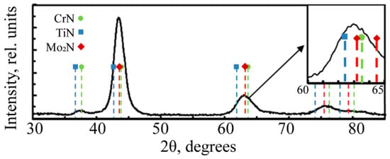
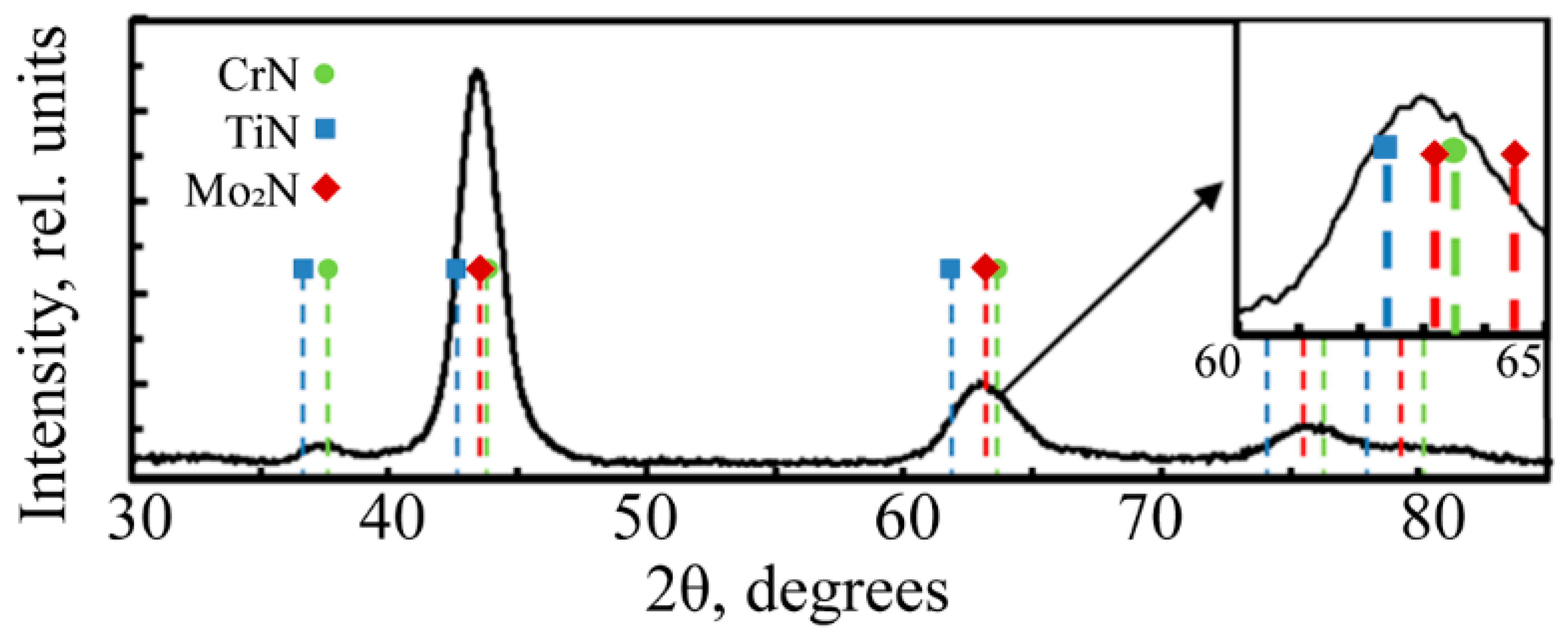
X-ray phase analysis data (Figure 3), refined by XPS, indicate that the Ti–Cr–Mo–Ni–N coating composition includes Ti1-xCrxN nitride, γ–Mo2N, and Ni.
Figure 3.
Typical XRD patterns of the deposited Ti–Cr–Mo–Ni–N coatings.
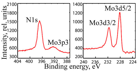
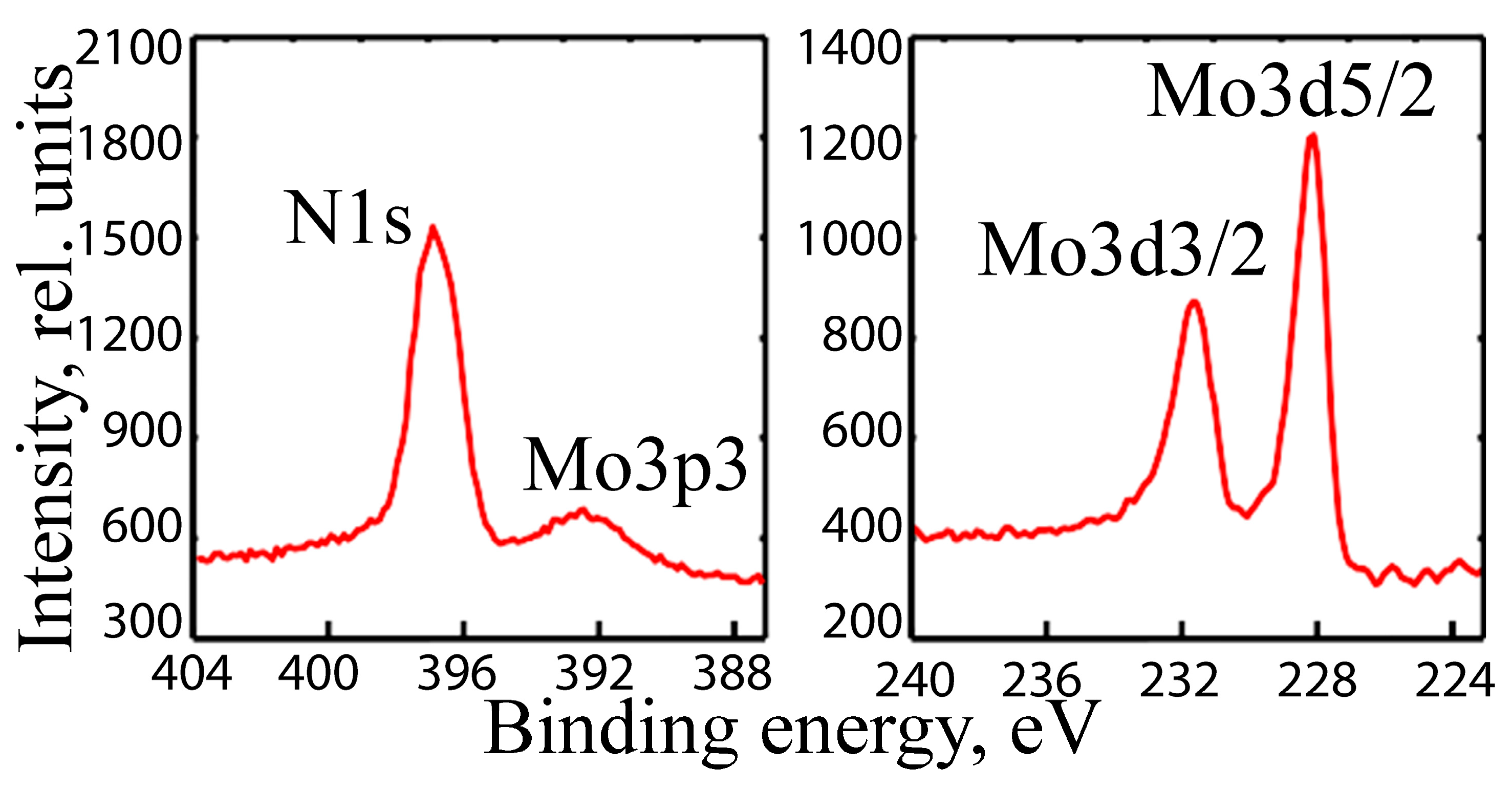
Molybdenum in the γ–Mo2N form is confirmed by two independent methods. First, the diffraction pattern (Figure 3) shows peak asymmetry, indicating this compound. Second, XPS (Figure 4) places Mo3d5/2 and N1s binding energies at 228.1 and 397.4 eV, characteristic of the γ–Mo2N nitride phase [39].
Figure 4.
Typical XPS spectra (N1s, Mo3p, and Mo3d) for Ti–Cr–Mo–Ni–N coatings.
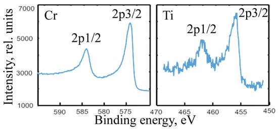
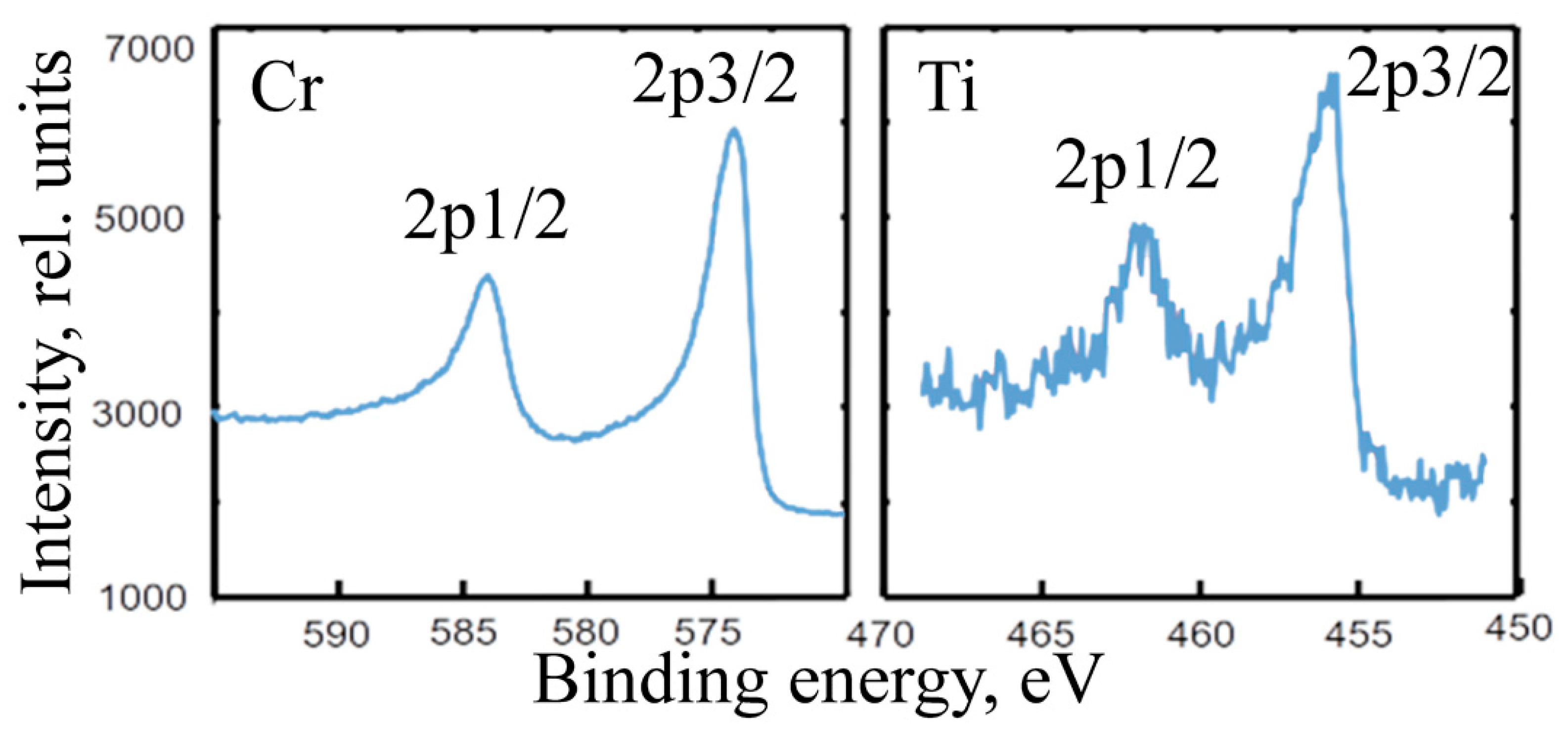
Titanium and chromium nitride sublayers with a cubic lattice, deposited prior to the molybdenum-containing layer, stabilize the γ–Mo2N phase. The Ti2p3/2 binding energy (Figure 5) across the approximately 170 nm profile remains at 455.3 eV, which corresponds to the Ti 2p3/2 binding energy in titanium nitride [40].
Figure 5.
Typical XPS spectra (Cr2p and Ti2p) for Ti–Cr–Mo–Ni–N coatings.
XPS spectra (Figure 5) exhibit two Cr2p lines: Cr2p3/2 at 574.9 eV and Cr2p1/2 at 584.4 eV. This confirms the CrN phase [39,40]—formed as substrates pass the chromium cathode—and (Ti,Cr)N, which forms as overlapping vapor fluxes from TiNi and Cr cathodes condense.
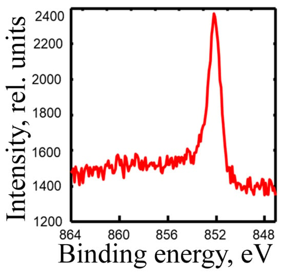
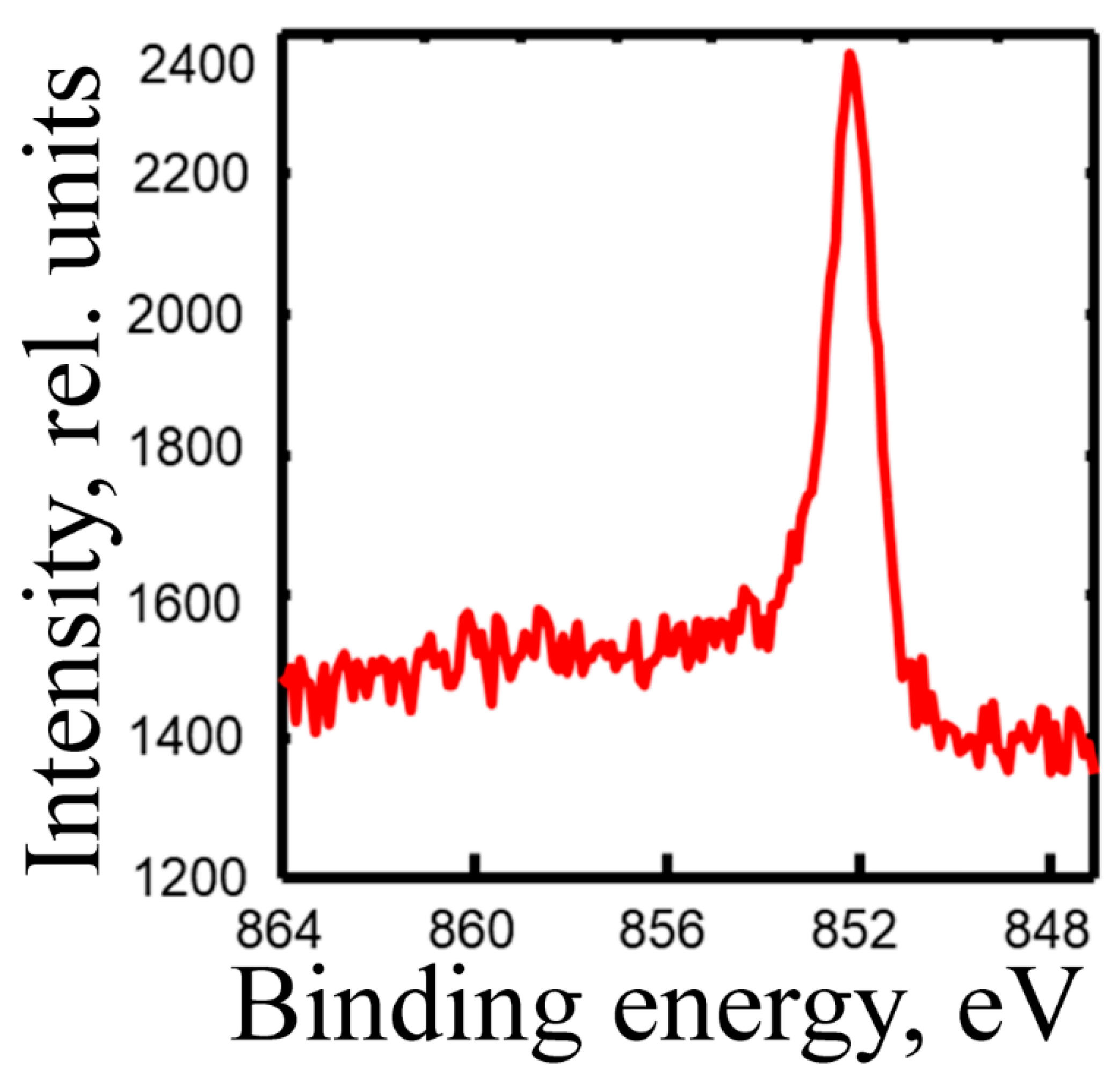
Although X-ray diffraction detects no Ni-bearing phases in Ti–Cr–Mo–Ni–N coatings, XPS (Figure 6) shows a Ni binding energy near 852.4 eV, characteristic solely of metallic Ni [41].
Figure 6.
Typical Ni2p3/2 XPS spectrum for Ti–Cr–Mo–Ni–N coatings.
The observed features are attributed to nickel’s much lower thermodynamic probability for bonding with nitrogen compared with the other coating elements [42,43,44,45]. Combined with nickel’s extremely low solubility in nitrides and the absence of clear diffraction peaks, this supports the view that nickel exists as an X-ray amorphous component—consistent with results reported in [22].
Ti–Cr–Mo–Ni–N coating substructure characteristics for the titanium-based nitride phase are listed in Table 2. On all substrates, the lattice parameter of the phase based on complex Cr–Ti–N is lower than that of stoichiometric TiN and larger than that of CrN [46].
Table 2.
Substructure characteristics for complex nitride Ti–Cr–N in Ti–Cr–Mo–Ni–N coatings.
This confirms solid solution formation—titanium in chromium nitride—during coating deposition, where the lattice parameter should increase given the Ti and Cr atomic radii ratio. Moreover, the determined average nitride phase lattice parameters match data from the literature [47] for Ti-in-CrN solid solutions at concentrations corresponding to those elements in our coatings. Simultaneously, the complex nitride-based phase exhibits large microstrains, whose origin lies in structural defects and compositional inhomogeneity. Their lowest values occur for coatings deposited on HG20 carbide alloy. As Table 2 shows, microstrain growth accompanies lattice parameter increases for the corresponding phases, consistent with published data. The combination of substantial microstrain and relatively small coherent scattering domains (CSDs) suggests that most of the strain arises from a nonuniform distribution of the components. If crystal structure defects were the sole strain source, their density would have to exceed 1012 cm−2, which is physically improbable.
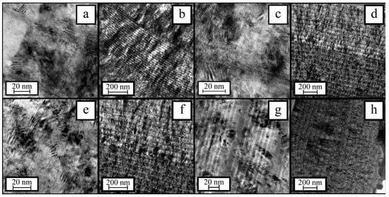
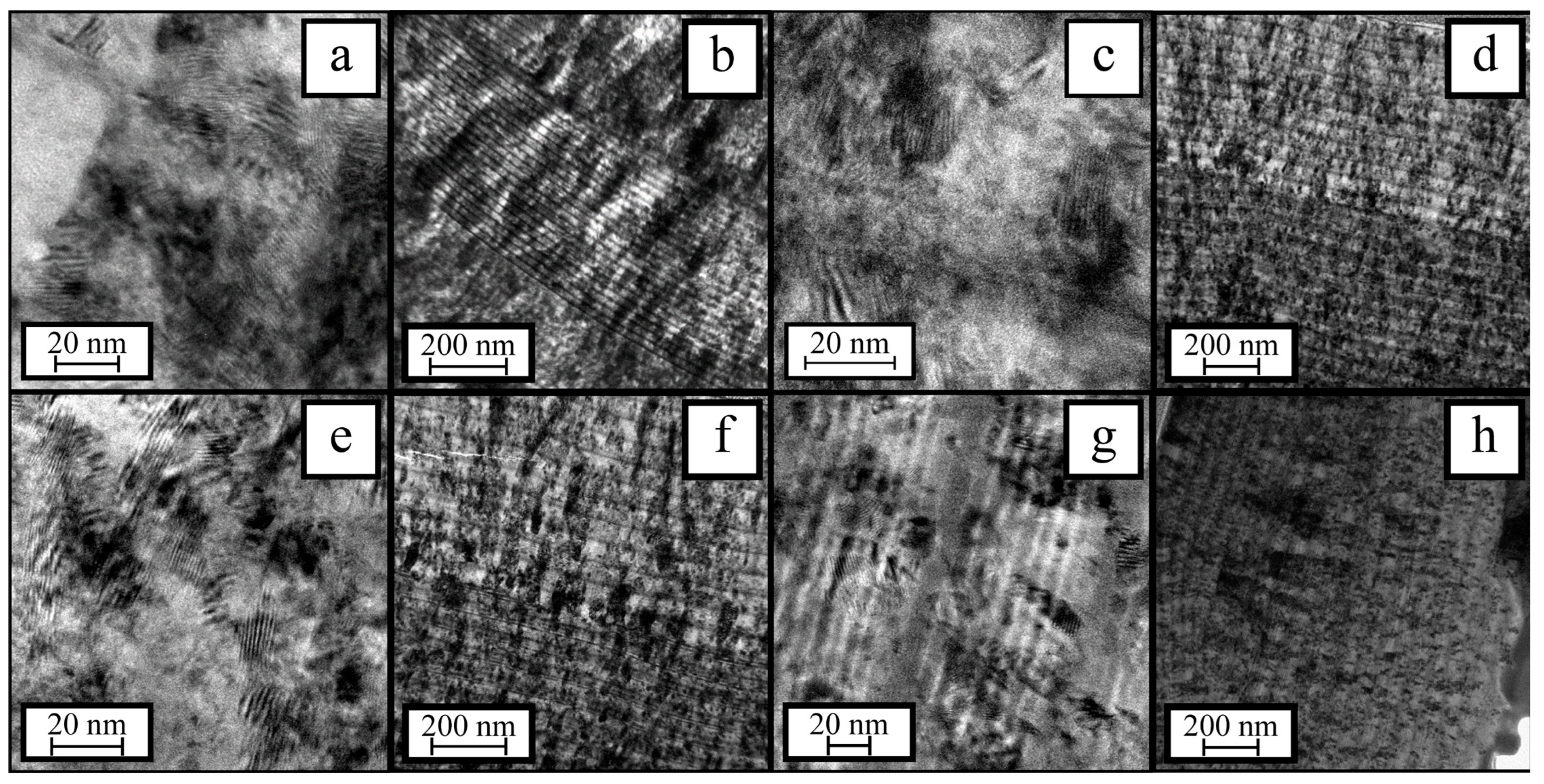
TEM analysis reveals that the Ti–Cr–Mo–Ni–N coatings on all tool material substrates form multilayer structures with a modulation period of approximately 70 nm (Figure 7). Individual crystallites grow through several layers.
Figure 7.
TEM images for Ti–Cr–Mo–Ni–N coatings on HG20 (a,b); HS123 (c,d); HV420 (e,f); and C80W1 (g,h) substrates.
Owing to the substrate–coating thermal expansion mismatch noted above, together with possible compositional and structural heterogeneities arising in growing PVD coatings [48,49], compressive or tensile macrostresses typically develop [50], noticeably affecting the overall coating–substrate composite properties [51,52,53,54]. Accordingly, their values were estimated by the Stoney method. Table 3 lists the obtained results.
Table 3.
Macrostress values estimated by the Stoney method for Ti–Cr–Mo–Ni–N coatings on various tool substrates.
The results show tensile stresses developing in the coating on a steel substrate. Compressive stresses, roughly equal in magnitude, occur in coatings on carbide alloy substrates. The calculated tensile macrostress values for the Ti–Cr–Mo–Ni–N coating on tool steel confirm the earlier inference that such stresses are likely here, and this factor’s effect on coating morphology—manifesting as macrolayering.
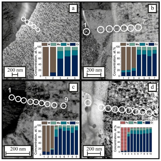
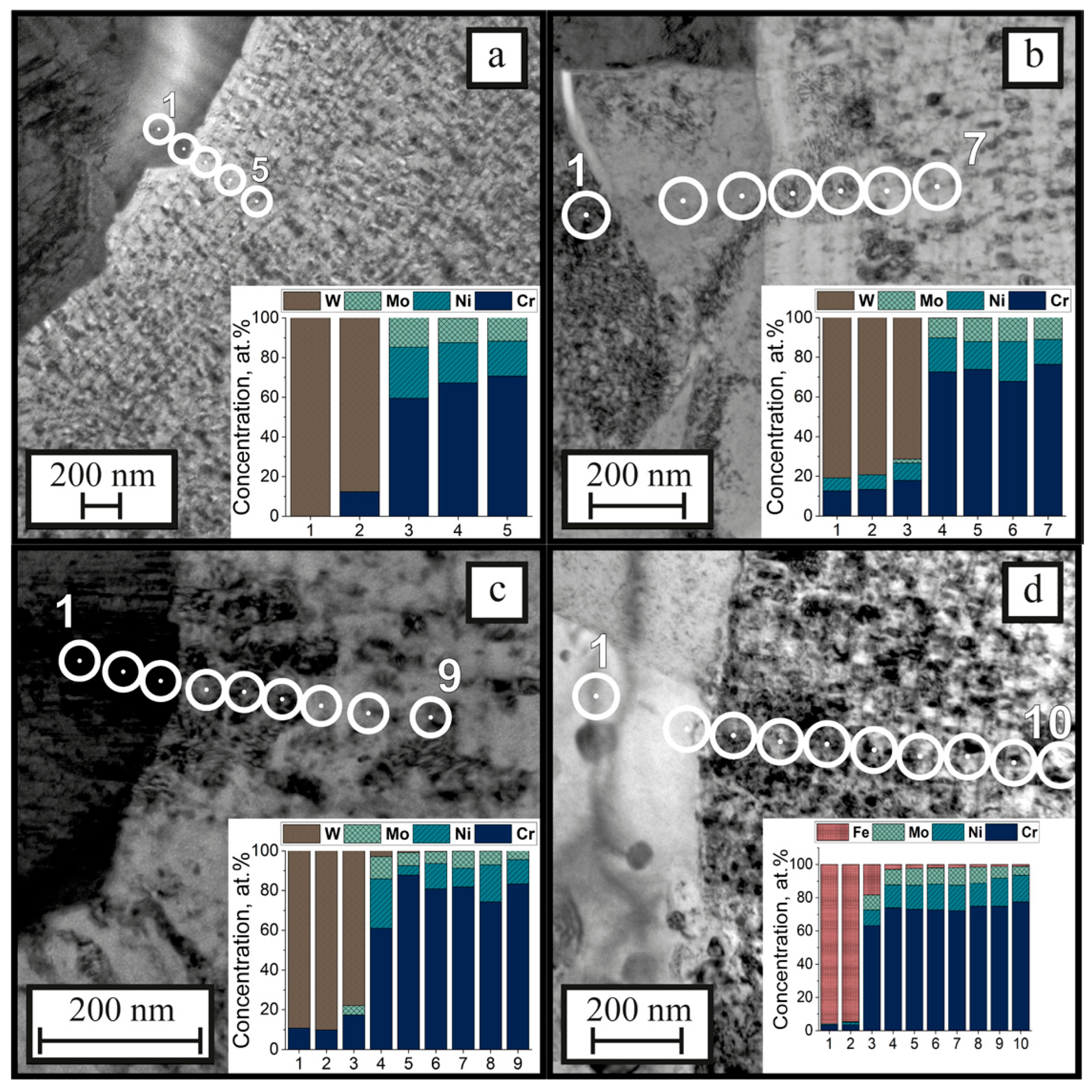
The diffusion transition zone was examined to assess how compositional inhomogeneity caused by mutual diffusion at the coating–substrate interface might affect structural stresses and their contribution to the overall macrostress. TEM imaging of near-interface regions and local X-ray microanalysis were employed. Depth determination error corresponded to half the diameter of the local analysis region. For the Ti–Cr–Mo–Ni–N coating on carbide alloys, the transition zone was defined by the diffusion depth for Cr, Ni, and Mo (coating elements) into the substrate and for W (substrate element) into the coating; and on C80W1 steel, by the diffusion depth for Cr, Ni, and Mo into the substrate and for Fe into the coating. The resulting TEM images and local elemental microanalysis data for the coating–substrate transition zones are presented in Figure 8.
Figure 8.
TEM images for the Ti–Cr–Mo–Ni–N coating/substrate interface on (a) HG20, (b) HS123, (c) HV420, and (d) C80W1, with local elemental compositions at the marked analysis points (spectrum numbers).
The estimated widths of the coating–substrate diffusion transition zones are listed in Table 4. The widest transition zone was observed for the C80W1 steel substrate.
Table 4.
Diffusion zone width at the Ti–Cr–Mo–Ni–N coating/substrate interface versus substrate thermal diffusivity.
This is attributed both to the higher diffusion mobility (diffusion coefficients D at temperatures reached in the coating–substrate contact zone) for iron atoms in the carbide alloy phases and coating elements in iron, compared with the mutual diffusion mobility for the marker elements (listed above) in Ti–Cr–Mo–Ni–N coatings and carbide substrates [55,56,57,58,59], and to local interface heating during deposition. This is also due to more efficient heat accumulation in the growth zone, since steel removes heat less effectively than carbide alloy substrates. Evidence for this effect comes from the temperature field simulation results presented in [28] for analogous-composition substrates and growing coatings under high-energy particle flux during arc-PVD Ti–Al–Ni–N deposition. Those simulations showed that the highest surface and coating–interior temperatures occur for the lower-thermal-diffusivity material—C80W1 steel. For the Ti–Cr–Mo–Ni–N coating, this effect may be even stronger, given the presence of molybdenum ions bombarding the substrate and the correspondingly greater energy transferred to the growing coating, according to:
where Z is the mean particle charge in the plasma flux; U (V) is the substrate bias potential; e (C) is the electron charge; and U0 (eV) is the initial ion energy in the arc-generated plasma used for cathode evaporation [60,61]. For Mo ions, U0 and Z exceed those for Al and Ti, which are the main Ti–Al–Ni–N coating constituents. The Z values for Mo, Cr, and Ti are 3.06, 2.09, and 2.03, respectively, while the corresponding U0 values are 151, 101, and 122 eV [62,63]. The 120–340 nm transition region at the substrate–coating interface may result from two factors: interdiffusion between the coating and substrate constituents and ion mixing during coating deposition, which can extend to depths of tens of nanometers. It should also be noted that surface roughness complicates accurate determination of the diffusion-zone width. However, given that the Ra values are identical for all substrates, it can be concluded that diffusion of the coating constituents into the steel substrate is more pronounced.
E(U) = U∙Z∙e + U0,
3.2. Physical–Mechanical, Tribological, and Adhesion to Substrate Properties for Ti–Cr–Mo–Ni–N Coatings Deposited on Different Substrates
The values for hardness (H), effective indentation modulus of the coating–substrate system (E), relative plastic deformation work (Wp), and the H/E and H3/E2 ratios, which characterize material resistance to elastic and plastic deformation [64,65], are listed in Table 5.
Table 5.
Ti–Cr–Mo–Ni–N coating physical–mechanical properties on tool substrates.
The carbide-supported systems exhibited higher measured H and E values than the steel-supported system. The differences in E reflect the effective indentation response of the coating–substrate systems, including the contribution of substrate compliance. The highest H/E and H3/E2 ratios were obtained for the steel-supported system. These indices are considered together with the observed wear-track morphology to assess substrate-dependent differences in the dominant wear mechanism. The lower measured hardness of the steel-supported system may be associated with differences in substrate support, the residual stress state of the coating, and compositional inhomogeneities near the coating–substrate interface [1,51,52].
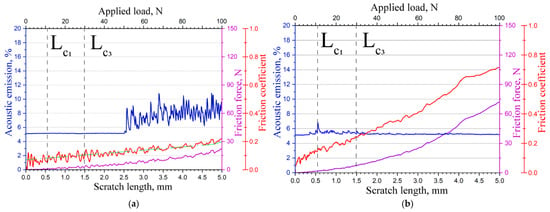
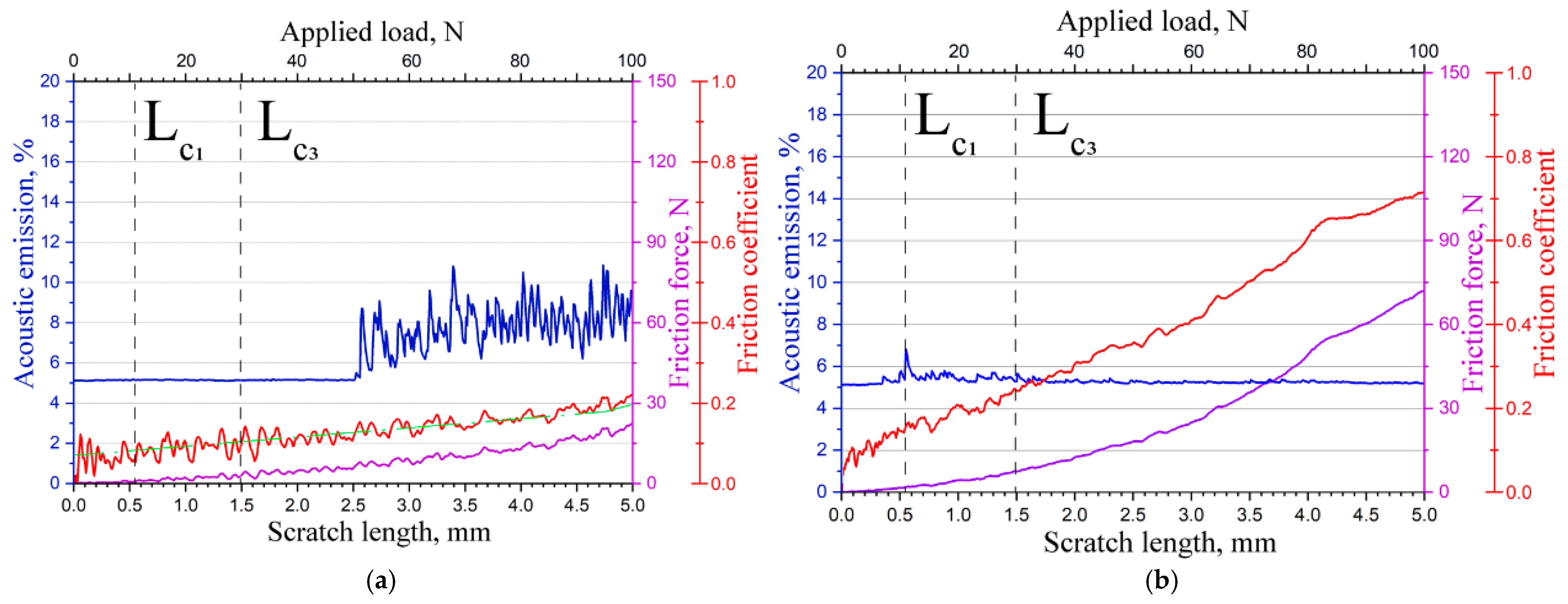
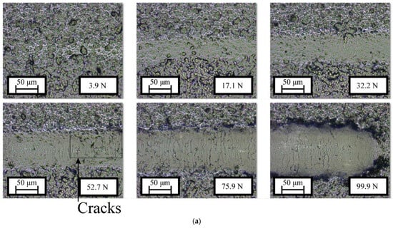
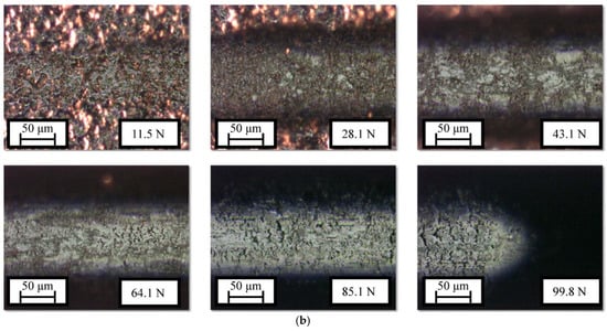
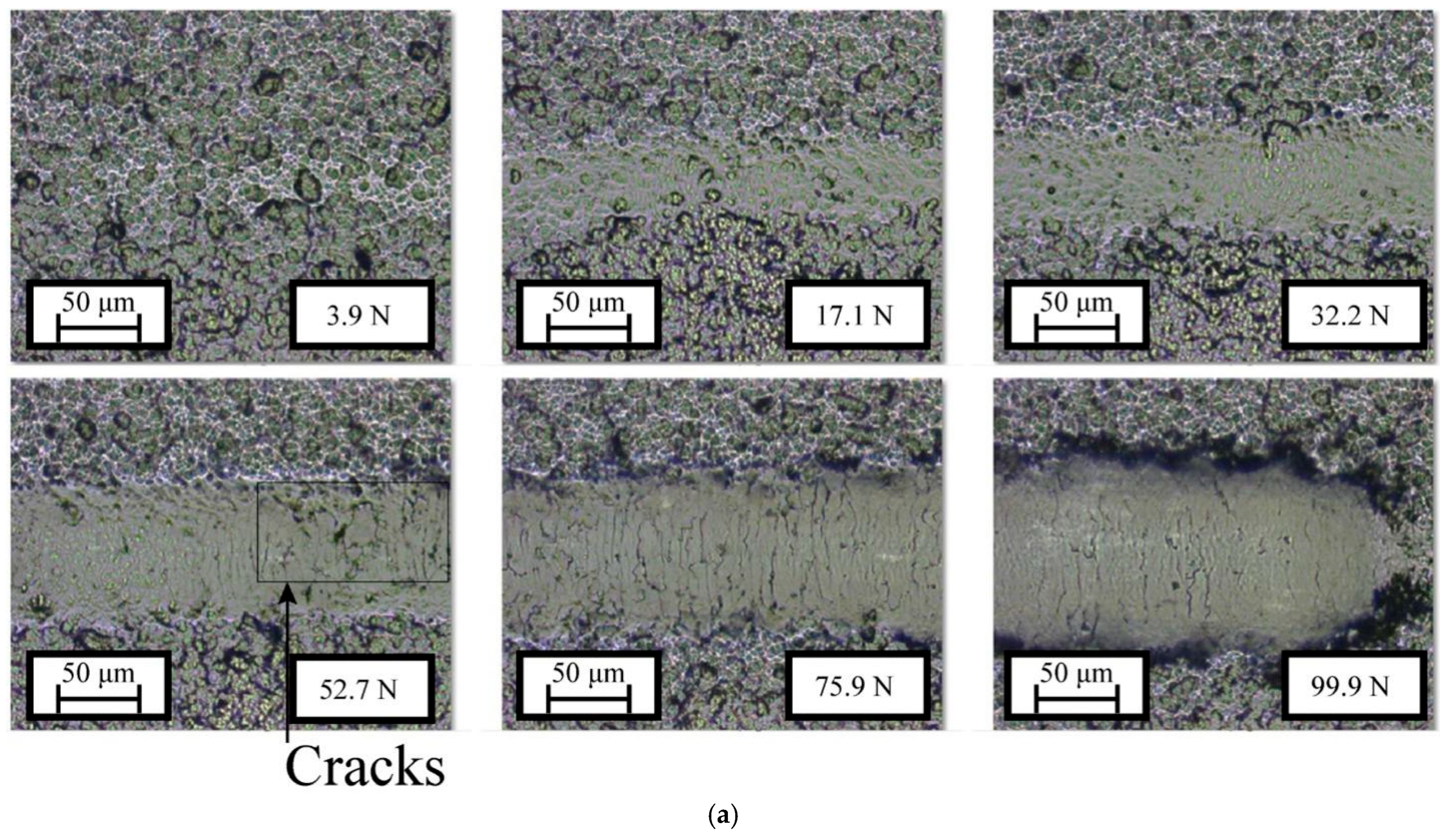
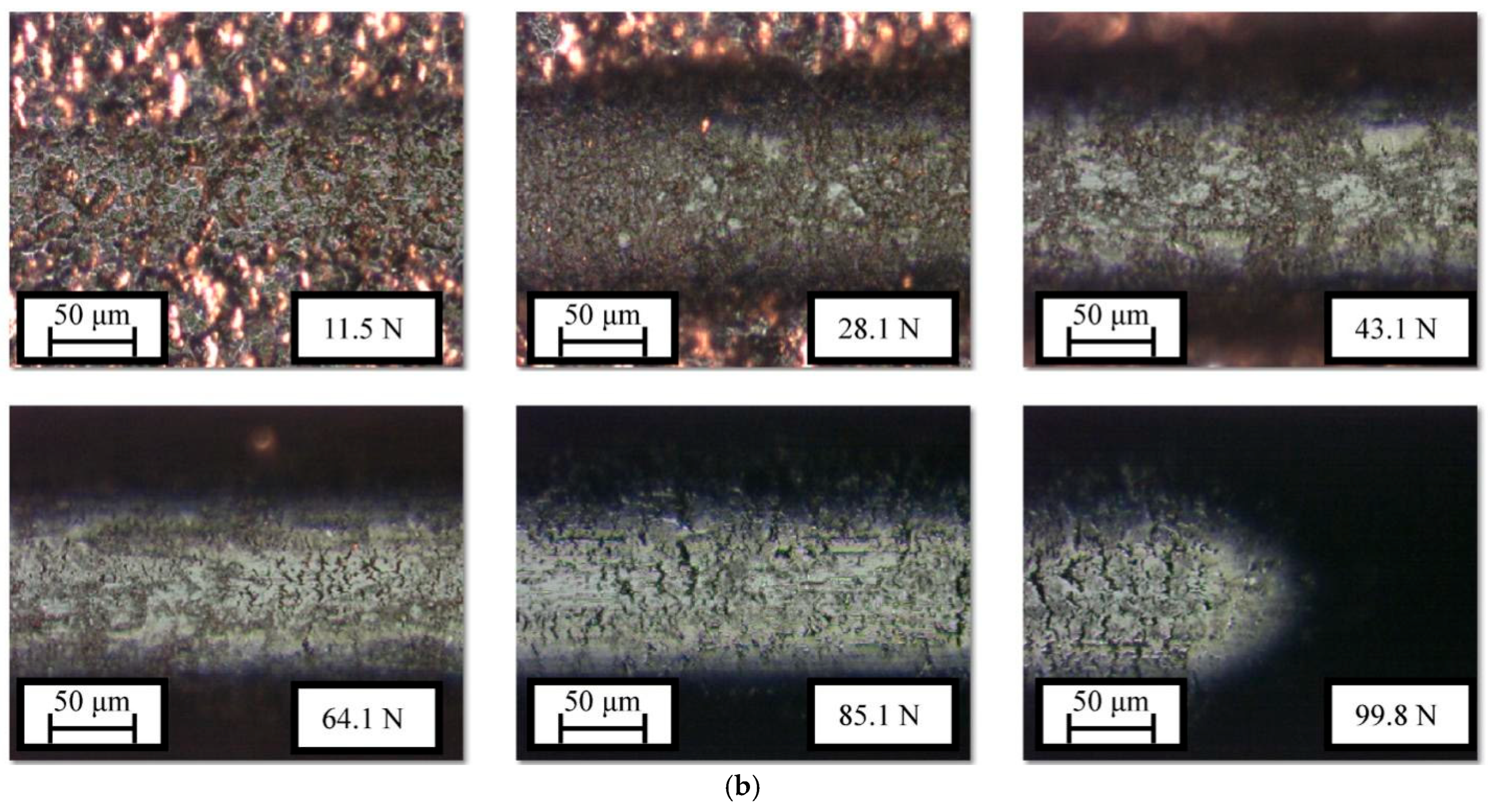
Investigations into adhesion strength for Ti–Cr–Mo–Ni–N ceramic–metal coatings on various tool materials revealed a cohesive failure mode for all coating–substrate composites studied. Since the processes during abrasive particle penetration resemble those in controlled scratch testing with an indenter [66,67], this method is regarded as a model for hard abrasive sliding over a surface under increasing load. Figure 9 and Figure 10 present typical scratch-test results for Ti–Cr–Mo–Ni–N coatings on various tool substrates: friction force (Ff), friction coefficient (μ), and acoustic emission (AE) curves, along with scratch micrographs produced by indenter sliding under increasing load.
Figure 9.
Typical variations in AE, μ and Ff during scratch testing of the Ti–Cr–Mo–Ni–N coating on HG20 (a) and C80W1 (b).
Figure 10.
Representative image of a scratch produced during adhesion testing of the Ti–Cr–Mo–Ni–N coating on HG20 (a) and C80W1 (b).
Table 6 lists critical loads Lc1 and Lc3 derived from scratch test data, indicating higher cohesive strength and scratch resistance for coatings on carbide alloy substrates and relatively low values on C80W1 steel (Lc2 was not determined, given the cohesive failure mode and no delamination). One possible explanation is that these coatings possess a higher fracture toughness (relative plastic deformation work of 56%–57% vs. 49%); however, this requires further verification (Table 5) and may be due to larger compressive macrostresses, which retard crack initiation and growth (Table 3) [68]. These results, together with the above considerations, may also indicate low abrasive wear resistance for coatings on C80W1 steel. This can be attributed to the relatively lower hardness for coatings on these substrates compared with those on carbide alloys (Table 5), since hardness is the key factor determining material resistance to such wear [69,70].
Table 6.
Tribological and adhesion properties for Ti–Cr–Mo–Ni–N coatings.
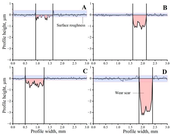
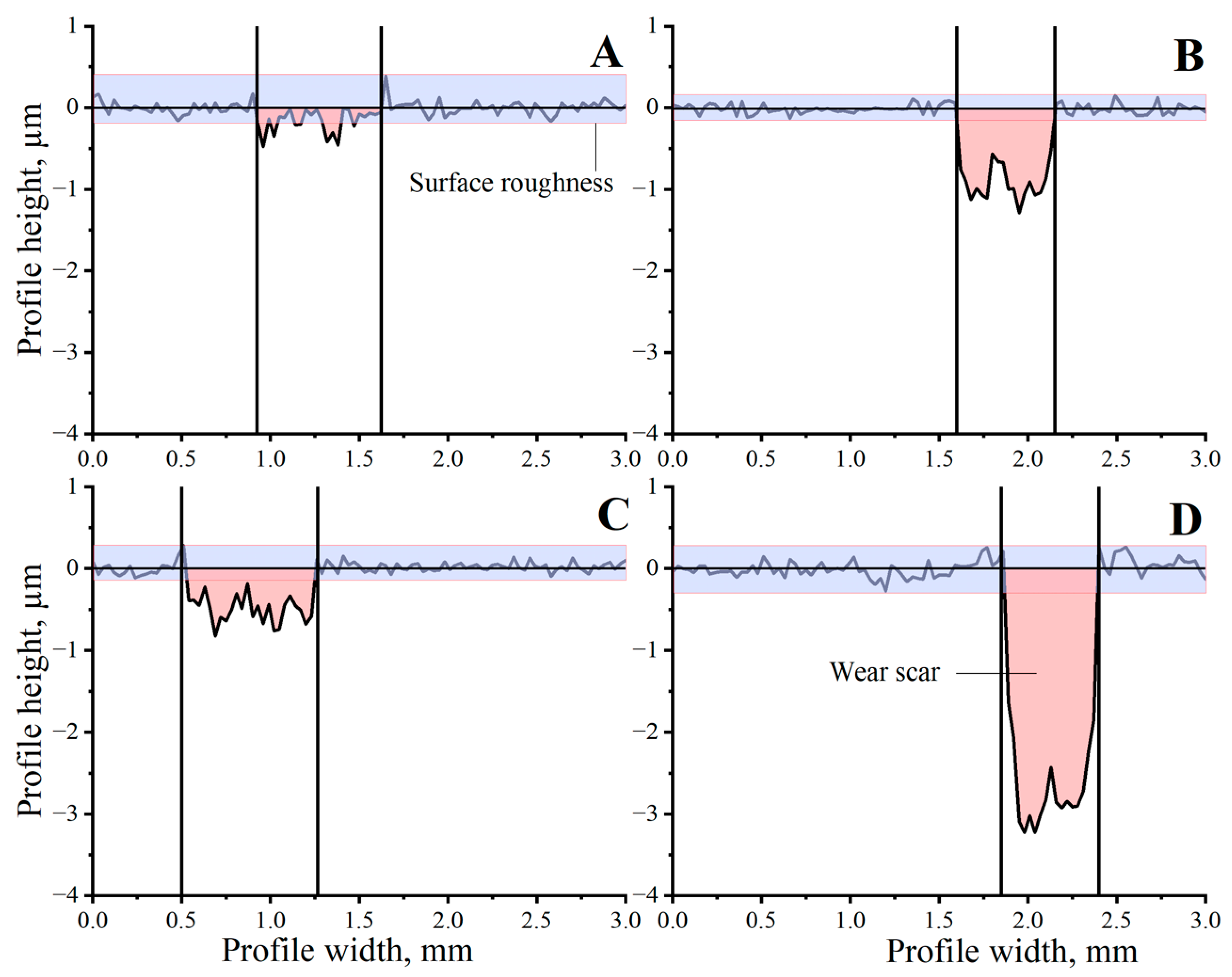
At room temperature, all Ti–Cr–Mo–Ni–N coatings on every substrate exhibited a similar friction coefficient (approximately 0.5), but they differed in wear rate. The wear rate of the coating on steel was significantly higher than that on the hard alloys, as evidenced by the wear craters, whose profiles allowed the wear depth (Figure 11) and the wear amount (Table 6) to be estimated.
Figure 11.
Typical wear track profiles for Ti–Cr–Mo–Ni–N coated specimens on carbide alloys (shown for HV420) (A,C) and tool steel (B,D) substrates after tribological testing at 20 (A,B) and 500 °C (C,D).
The relationship between the measured indentation indices and wear behavior depends on the substrate. The coating on C80W1 steel exhibits the highest H/E and H3/E2 ratios (Table 5), together with pronounced wear. These ratios characterize the indentation response under the specified test conditions and may include contributions from substrate compliance and surface roughness. Their higher values therefore do not necessarily imply better wear performance across systems with different substrates.
The wear-track observations provide additional evidence for interpreting this behavior. On the carbide-supported coatings, wear occurs through local fragment detachment within the track and along its edges (Figure 12a,b). In contrast, the wear track on steel exhibits features consistent with plastic deformation and displacement of the coating layers (Figure 12c,d). Taken together, the mechanical indices and morphological observations support a substrate-dependent change in the dominant wear mechanism, from local fragmentation on the carbide substrates to deformation-assisted damage and layer displacement on steel. H/E and H3/E2 thus remain important comparative indices, while their relationship with wear must be interpreted in the context of the damage mechanism of each coating–substrate system.
Figure 12.
Wear track morphology for the Ti–Cr–Mo–Ni–N coating on carbide alloy (a,b) and on tool steel (c,d).
At 500 °C, the Ti–Cr–Mo–Ni–N coatings on carbide alloys exhibit similar friction coefficients of approximately 0.54–0.59, which are slightly higher than those at room temperature (Table 6). Noticeable transfer of wear debris from the counterbody to the wear track initially hindered wear-rate measurements. After loose wear debris was removed using compressed air and a soft brush, the wear-track profiles were measured and used to estimate the specific wear rates reported in Table 6. The coating on steel shows a slight friction coefficient decrease at 500 °C (to 0.47 vs. 0.49) accompanied by a higher wear rate (Figure 11B,D). The lower friction coefficient for Ti–Cr–Mo–Ni–N coatings on steel stems from their macrolayered structure, described earlier when discussing coating morphology on this substrate, and the resulting decrease in their shear strength due to poor interlayer adhesion, which reduces friction force [69]. The higher friction coefficients for Ti–Cr–Mo–Ni–N coatings on carbide alloy substrates at high temperature can be explained by chromium being the main coating element; its oxidation in air during high-temperature tribological tests forms Cr2O3-based wear debris, which acts as an abrasive in the contact zone and raises friction force [71]. Molybdenum present in the coating, which, according to our and others’ studies, should improve tribological performance at high temperature through MoO3 lubricious phase formation [72,73,74,75,76], here, has no significant effect due to its low content (approximately 4 at.%) against high chromium (approximately 35 at.%).
4. Conclusions
Analysis of the structure and properties of Ti–Cr–Mo–Ni–N ceramic–metal coatings on different tool substrates revealed a difference in morphology between coatings on tool steel and those on carbide-based substrates, namely the appearance of globular formations on tool steel. This is attributed to hindered heat removal from the ion flux bombarding the substrate, due to steel’s lower thermal diffusivity compared with the carbide alloys used. This leads to a lower cooling rate for the growing coating on steel and thus a possible vapor–liquid–solid phase transition, whereas on carbide alloy substrates coating formation proceeds via a vapor–solid transition. Additionally, these coatings show stepped surface areas, indicating a macrolayered structure. This difference likely results from tensile thermal stresses (in contrast to coatings on carbide alloys), which at a certain growth stage rupture the growing layer, exposing fresh surface where new coating phase nuclei form and grow, producing a new layer. The same reason may explain the relatively lower hardness for the coating on steel (20.3 ± 1.1 GPa) compared with coatings on carbide substrates (25.1 ± 2.2–21.7 ± 1.1 GPa).
Relatively low cohesive strength was found for the coating on tool steel compared with coatings on carbide alloy substrates. This effect stems from tensile structural macrostresses in the former case and from the coating morphology on tool steel—its macromultilayer nature, which reduces shear strength. At the same time, the latter may account for the relatively lower friction coefficient for this coating compared with carbide-based coatings.
The studied coatings exhibit good tribological performance both at room and elevated temperatures—relatively low wear rates, with the highest wear rate for the coating on tool steel.
Considering the functional property study for Ti–Cr–Mo–Ni–N coatings on various tool substrates, it can be concluded that they may be effectively used as strengthening coatings on carbide alloys belonging to the HG20, HS123, and HV420 groups. Their effectiveness on carbon tool steel would be reduced due to lower hardness, lower cohesive strength, and higher wear rate.
Author Contributions
Conceptualization, I.V.B. and A.V.C.; methodology, I.V.B. and A.V.C.; validation, D.S.B.; formal analysis, D.S.B., I.V.B., and A.P.D.; investigation, I.V.B. and A.V.C.; resources, I.V.B.; data curation, D.S.B., I.V.B., and A.V.C.; writing—original draft preparation, D.S.B. and I.V.B.; writing—review and editing, D.S.B., A.P.D., and R.A.B.; visualization, D.S.B. and R.A.B.; supervision, I.V.B.; project administration, I.V.B.; funding acquisition, D.S.B., I.V.B., A.P.D., and R.A.B. All authors have read and agreed to the published version of the manuscript.
Funding
This work was supported by the Ministry of Science and Higher Education of the Russian Federation (state assignment, project no. FSME-2026-0008).
Data Availability Statement
The raw and processed data supporting the findings of this study are available from the corresponding authors upon reasonable request.
Conflicts of Interest
The authors declare no conflicts of interest.
References
- Kumar, D.D.; Kumar, N.; Kalaiselvam, S.; Dash, S.; Jayavel, R. Substrate effect on wear resistant transition metal nitride hard coatings: Microstructure and tribomechanical properties. Ceram. Int. 2015, 41, 9849–9861. [Google Scholar] [CrossRef] [Scilit]
- Wang, Y.H.; Guo, F.; Ren, H.; Hu, S.Y.; Chen, Y.J.; Zhao, Y.H.; Gong, F.; Xie, Z.W. Enhancing wear resistance of TiN coating by gradient bias voltage and arc-enhanced glow discharge. Ceram. Int. 2022, 48, 8746–8750. [Google Scholar] [CrossRef] [Scilit]
- Luo, C.W.; Zhou, Q.; Liao, B.; Hua, Q.S.; Ou, Y.X.; Wang, H.Q.; Chen, S.N.; Yan, W.Q.; Huang, H.Z.; Zhao, G.Q.; et al. Structure, mechanical and tribological properties of thick CrNx coatings deposited by HiPIMS. Vacuum 2022, 203, 111253. [Google Scholar] [CrossRef] [Scilit]
- Bai, H.; Bai, Y.; Li, J.; Gao, J.; Jian, J.; Chen, H.; Zhao, L.; Bai, B.; He, J.; Leng, X.; et al. Tribological and mechanical properties of structure-modulated CrXN coatings fabricated by HiPIMS. Surf. Coat. Technol. 2025, 496, 131646. [Google Scholar] [CrossRef] [Scilit]
- Schulz, W.; Köhn, F.; Kolb, D.; Balzer, M.; Riegel, H.; Albrecht, J. Controlling friction and wear with anisotropic microstructures in MoN-coated surfaces. Tribol. Lett. 2021, 69, 152. [Google Scholar] [CrossRef] [Scilit]
- Akbarzadeh, M.; Shafyei, A.; Salimijazi, H.R. Characterization of TiN, CrN and (Ti,Cr)N coatings deposited by cathodic arc evaporation. Int. J. Eng. 2014, 27, 1127–1132. [Google Scholar] [CrossRef] [Scilit][Green Version]
- Li, F.; Dai, W.; Wang, Q.; Li, H.; Wu, Z. Dry friction performances of MoNx coatings deposited by high–power pulsed magnetron sputtering. Magnetochemistry 2023, 9, 60. [Google Scholar] [CrossRef] [Scilit]
- Gassner, G.; Mayrhofer, P.H.; Kutschej, K.; Mitterer, C.; Kathrein, M. Magnéli phase formation of PVD Mo–N and W–N coatings. Surf. Coat. Technol. 2006, 201, 3335–3341. [Google Scholar] [CrossRef] [Scilit]
- Chang, Z.K.; Wan, X.S.; Pei, Z.L.; Gong, J.; Sun, C. Microstructure and mechanical properties of CrN coating deposited by arc ion plating on Ti6Al4V substrate. Surf. Coat. Technol. 2011, 205, 4690–4696. [Google Scholar] [CrossRef] [Scilit]
- Yoo, Y.H.; Le, D.P.; Kim, J.G.; Kim, S.K.; Vinh, P.V. Corrosion behavior of TiN, TiAlN, TiAlSiN thin films deposited on tool steel in the 3.5 wt.% NaCl solution. Thin Solid Films 2008, 516, 3544–3548. [Google Scholar] [CrossRef] [Scilit]
- Nam, N.D.; Vaka, M.; Hung, N.T. Corrosion behavior of TiN, TiAlN, TiAlSiN–coated 316L stainless steel in simulated proton exchange membrane fuel cell environment. J. Power Sources 2014, 268, 240–245. [Google Scholar] [CrossRef] [Scilit]
- Peng, Y.; Du, P.; Liu, Y.; Wang, H.; Liu, S.; Zhang, W. Investigation on microstructures and high-temperature oxidation resistance of Cr coatings on Zircaloy-4 by multi-arc ion plating technology. Materials 2022, 15, 6755. [Google Scholar] [CrossRef] [Scilit] [PubMed]
- Chen, H.; Yuan, G. High-temperature oxidation behavior of (Ti,Cr)N coating deposited on 4Cr13 stainless steel by multi–arc ion plating. Rare Met. Mater. Eng. 2014, 43, 1084–1087. [Google Scholar] [CrossRef] [Scilit]
- Kim, K.H.; Choi, E.Y.; Hong, S.G.; Park, B.G.; Kim, J.H. Syntheses and mechanical properties of Cr–Mo–N coatings by a hybrid coating system. Surf. Coat. Technol. 2006, 201, 4068–4072. [Google Scholar] [CrossRef] [Scilit]
- Moussaoui, A.; Abboudi, A.; Aissani, L.; Belgroune, A.; Cheriet, A.; Alhussein, A.; Rtimi, S. Effect of Mo addition on the mechanical and tribological properties of magnetron sputtered TiN films. Surf. Coat. Technol. 2023, 470, 129862. [Google Scholar] [CrossRef] [Scilit]
- Scientific Group Thermodata Europe (SGTE). Ternary Alloy Systems; Springer: Berlin/Heidelberg, Germany, 2010. [Google Scholar]
- Musil, J.; Karvankova, P.; Kasl, J. Hard and superhard Zr–Ni–N nanocomposite films. Surf. Coat. Technol. 2001, 139, 101–109. [Google Scholar] [CrossRef] [Scilit]
- Veprek, S.; Veprek, G.J.; Karvankova, P.; Prochazka, J. Different approaches to superhard coatings and nanocomposites. Thin Solid Films 2005, 476, 1–29. [Google Scholar] [CrossRef] [Scilit]
- Karvaňková, P.; Männling, H.-D.; Eggs, C.; Veprek, S. Thermal stability of ZrN–Ni and CrN–Ni superhard nanocomposite coatings. Surf. Coat. Technol. 2001, 146–147, 280–285. [Google Scholar] [CrossRef] [Scilit]
- Semenov, A.P.; Tsyrenov, D.B.-D.; Semenova, I.A. Synthesis of TiN–Cu nanocomposite coatings using combined vacuum-arc evaporation, magnetron sputtering, and ion beam sputtering. Russ. Metall. Met. 2023, 2023, 303–305. [Google Scholar] [CrossRef] [Scilit]
- Lopez-Cabanas, I.; LLorca, J.; González-Arrabal, R.; Meletis, E.I.; Molina-Aldareguia, J.M. High throughput optimization of hard and tough TiN/Ni nanocomposite coatings by reactive magnetron sputter deposition. Surf. Coat. Technol. 2021, 418, 127226. [Google Scholar] [CrossRef] [Scilit]
- Belov, D.S.; Blinkov, I.V.; Volkhonskii, A.O. The effect of Cu and Ni on the nanostructure and properties of arc-PVD coatings based on titanium nitride. Surf. Coat. Technol. 2014, 260, 186–197. [Google Scholar] [CrossRef] [Scilit]
- Chernogor, A.; Klimashin, F.; Volkhonskii, A.; Blinkov, I.; Mayrhofer, P. The impact of Ni and Mo on growth–morphology and mechanical properties of arc evaporated Ti–Cr–N hard coatings. Surf. Coat. Technol. 2019, 377, 124917. [Google Scholar] [CrossRef] [Scilit]
- Wang, T.; Zhang, G.; Jiang, B. Comparison in mechanical and tribological properties of CrTiAlMoN and CrTiAlN nano–multilayer coatings deposited by magnetron sputtering. Appl. Surf. Sci. 2016, 363, 217–224. [Google Scholar] [CrossRef] [Scilit]
- Chang, Y.-Y.; Chuang, C.-C. Deposition of multicomponent AlTiCrMoN protective coatings for metal cutting applications. Coatings 2020, 10, 605. [Google Scholar] [CrossRef] [Scilit]
- Stylianou, R.; Velic, D.; Daves, W.; Ecker, W.; Stark, A.; Schell, N.; Tkadletz, M.; Schalk, N.; Czettl, C.; Mitterer, C. Stress relaxation through thermal crack formation in CVD TiCN coatings grown on WC–Co with different Co contents. Int. J. Refract. Met. Hard Mater. 2020, 86, 105102. [Google Scholar] [CrossRef] [Scilit]
- Musa, M.Š.; Sakoman, M.; Ćorić, D.; Fabijanić, T.A. Exploitation and wear properties of nanostructured WC–Co tool modified with plasma–assisted chemical vapor deposition TiBN coating. Metals 2021, 11, 333. [Google Scholar] [CrossRef] [Scilit]
- Belov, D.S.; Demirov, A.P.; Blinkov, I.V.; Sergevnin, V.S.; Chernogor, A.V.; Kiryukhantsev, P.V.; Anikin, V.N. Structure and properties features of CA–PVD Ti–Al–Ni–N coatings deposited on carbide alloys and tool steel substrates. Surf. Coat. Technol. 2024, 494, 131348. [Google Scholar] [CrossRef] [Scilit]
- Oliver, W.C.; Pharr, G.M. An improved technique for determining hardness and elastic modulus using load and displacement sensing indentation experiments. J. Mater. Res. 1992, 7, 1564–1583. [Google Scholar] [CrossRef] [Scilit]
- Zhou, Y.; Asaki, R.; Soe, W.-H.; Yamamoto, R.; Chen, R.; Iwabuchi, A. Hardness anomaly, plastic deformation work and fretting wear properties of polycrystalline TiN/CrN multilayers. Wear 1999, 236, 159–164. [Google Scholar] [CrossRef] [Scilit]
- Henry, P.; Pac, M.-J.; Rousselot, C.; Tuilier, M.-H. Wear mechanisms of titanium and aluminium nitride coatings: A microtribological approach. Surf. Coat. Technol. 2013, 223, 79–86. [Google Scholar] [CrossRef] [Scilit]
- Stoney, G.G. The tension of metallic films deposited by electrolysis. Proc. R. Soc. Lond. Ser. A 1909, 82, 172–175. [Google Scholar] [CrossRef] [Scilit]
- Zhao, Y.; Chen, S.; Chen, Y.; Wu, S.; Xie, W.; Yan, W.; Wang, S.; Liao, B.; Zhang, S. Super–hard and anti–corrosion (AlCrMoSiTi)Nx high entropy nitride coatings by multi–arc cathodic vacuum magnetic filtration deposition. Vacuum 2022, 195, 110685. [Google Scholar] [CrossRef] [Scilit]
- Zhang, L.; Yang, H.; Pang, X.; Gao, K.; Volinsky, A.A. Microstructure; residual stress, and fracture of sputtered TiN films. Surf. Coat. Technol. 2013, 224, 120–125. [Google Scholar] [CrossRef] [Scilit]
- Davis, J.R. (Ed.) ASM Specialty Handbook: Tool Materials; ASM International: Materials Park, OH, USA, 1995. [Google Scholar]
- Schultrich, B.; Poeßnecker, W. Thermal conductivity of cemented carbides. J. Therm. Anal. 1988, 33, 305–310. [Google Scholar] [CrossRef] [Scilit]
- Wen, S.; Du, Y.; Tan, J.; Liu, Y.; Zhou, P.; Long, J.; Kaptay, G. A novel physical model for describing thermal conductivity of composite materials: Application to the measured values in a two–phase WC–Co system. Acta Mater. 2020. [Google Scholar] [CrossRef] [Scilit]
- Wen, S.; Du, Y.; Tan, J.; Liu, Y.; Zhou, P.; Long, J.; Kaptay, G. A new model for thermal conductivity of “continuous matrix / dispersed and separated 3D–particles” type composite materials and its application to WC–M (M = Co, Ag) systems. J. Mater. Sci. Technol. 2022, 97, 123–133. [Google Scholar] [CrossRef] [Scilit]
- Qi, D.; Lei, H.; Wang, T.; Pei, Z.; Gong, J.; Sun, C. Mechanical, microstructural and tribological properties of reactive magnetron sputtered Cr–Mo–N films. J. Mater. Sci. Technol. 2015, 31, 55–64. [Google Scholar] [CrossRef] [Scilit]
- Bertóti, I. Characterization of nitride coatings by XPS. Surf. Coat. Technol. 2002, 151–152, 194–203. [Google Scholar] [CrossRef] [Scilit]
- He, C.; Xie, L.; Zhang, J.; Ma, G.; Du, Z.; Wang, J.; Zhao, D. Microstructure and mechanical properties of reactive sputtered nanocrystalline Ti–Al–Ni–N thin films. Surf. Coat. Technol. 2017, 320, 472–477. [Google Scholar] [CrossRef] [Scilit]
- Huber, F.; Gmelin, L.; Meyer, R.J.; Pietsch, E. Gmelin Handbook of Inorganic Chemistry, 8th ed.; Springer: Berlin/Heidelberg, Germany, 1989; Volume B5, pp. 1–66. [Google Scholar]
- Okamoto, H. N–Ti (Nitrogen–Titanium). J. Phase Equilibria Diffus. 2013, 34, 151–152. [Google Scholar] [CrossRef] [Scilit]
- Mills, T. Thermodynamic relations in the chromium–nitrogen system. J. Less–Common Met. 1972, 26, 223–234. [Google Scholar] [CrossRef] [Scilit]
- Guillermet, A.F.; Frisk, K. Thermodynamic properties of Ni nitrides and phase stability in the Ni–N system. Int. J. Thermophys. 1991, 12, 417–431. [Google Scholar] [CrossRef] [Scilit]
- Ponce-Pérez, R.; Corona-García, C.A.; Hernandez, J.M.G.; Reyes-Serrato, A.; Corbett, J.P.; Guerrero-Sánchez, J. Atomic-scale description of the magnetic TiN|FeCo multilayers. ACS Omega 2024, 9, 24721–24727. [Google Scholar] [CrossRef] [Scilit] [PubMed]
- Paksunchai, C.; Denchitcharoen, S.; Chaiyakun, S.; Limsuwan, P. Effect of sputtering current on structure and morphology of (Ti1-xCrx)N thin films deposited by reactive unbalanced magnetron co–sputtering. Procedia Eng. 2012, 32, 875–881. [Google Scholar] [CrossRef] [Scilit]
- Abadias, G.; Daniel, R. Stress in physical vapor deposited thin films: Measurement methods and selected examples. In Handbook of Modern Coating Technologies: Advanced Characterization Methods; Aliofkhazraei, M., Ali, N., Chipara, M., Laidani, N.B., De Hosson, J.T.M., Eds.; Elsevier: Amsterdam, The Netherlands, 2021; pp. 359–436. [Google Scholar] [CrossRef] [Scilit]
- Huff, M. Review paper: Residual stresses in deposited thin-film material layers for micro- and nano-systems manufacturing. Micromachines 2022, 13, 2084. [Google Scholar] [CrossRef] [Scilit] [PubMed]
- Wu, X.; Jiang, Y.; Wu, T.; Zuo, B.; Bian, S.; Lu, K.; Zhao, L.; Yu, L.; Xu, J. Insight into the mechanisms of nitride films with excellent hardness and lubricating performance: A review. Nanomaterials 2023, 13, 2205. [Google Scholar] [CrossRef] [Scilit] [PubMed]
- Wang, C.T.; Hakala, T.J.; Laukkanen, A.; Ronkainen, H.; Holmberg, K.; Gao, N.; Wood, R.J.K.; Langdon, T.G. An investigation into the effect of substrate on the load–bearing capacity of thin hard coatings. J. Mater. Sci. 2016, 51, 4390–4398. [Google Scholar] [CrossRef] [Scilit]
- Lepick, M.; Gradzka, M.; Pieniak, D.; Pasierbiewicz, K.; Krynsk, K.; Niewczas, A. Tribological performance of titanium nitride coatings: A comparative study on TiN–coated stainless steel and titanium alloy. Wear 2019, 422–423, 68–80. [Google Scholar] [CrossRef] [Scilit]
- Panjan, P.; Miletić, A.; Drnovšek, A.; Terek, P.; Čekada, M.; Kovačević, L.; Panjan, M. Cracking resistance of selected PVD hard coatings. Coatings 2024, 14, 1452. [Google Scholar] [CrossRef] [Scilit]
- Vereschaka, A.A.; Grigoriev, S.N. Study of cracking mechanisms in multi-layered composite nano-structured coatings. Wear 2017, 378–379, 43–57. [Google Scholar] [CrossRef] [Scilit]
- Kumar, P.; Jithin, M.A.; Mohan, S.; Avasthi, S. Hundred–fold reduction in iron diffusivity in titanium nitride diffusion barrier on steel by microstructure engineering. Thin Solid Films 2020, 716, 138416. [Google Scholar] [CrossRef] [Scilit]
- Sabitzer, C.; Steinkellner, C.; Koller, C.M.; Polcik, P.; Rachbauer, R.; Mayrhofer, P.H. Diffusion behavior of C, Cr, and Fe in arc evaporated TiN– and CrN–based coatings and their influence on thermal stability and hardness. Surf. Coat. Technol. 2015, 275, 185–192. [Google Scholar] [CrossRef] [Scilit]
- Dahan, I.; Admon, U.; Frage, N.; Sariel, J.; Dariel, M.P. Diffusion in Ti/TiC multilayer coatings. Thin Solid Films 2000, 377–378, 687–693. [Google Scholar] [CrossRef] [Scilit]
- Nitta, H.; Yamamoto, T.; Kanno, R.; Takasawa, K.; Iida, T.; Yamazaki, Y.; Ogu, S.; Iijima, Y. Diffusion of molybdenum in α–iron. Acta Mater. 2002, 50, 4117–4125. [Google Scholar] [CrossRef] [Scilit]
- Hirano, K.; Cohen, M.; Averbach, B. Diffusion of nickel into iron. Acta Metall. 1961, 9, 440–445. [Google Scholar] [CrossRef] [Scilit]
- Zhao, H.; Zheng, Z.; Akhavan, B.; Tsoutas, K.; Sun, L.; Zhou, H.; Bilek, M.M.; Liu, Z. The fabrication and growth mechanism of AlCrFeCoNiCu0.5 HEA thin films by substrate-biased cathodic arc deposition. Sci. Rep. 2023, 13, 198. [Google Scholar] [CrossRef] [Scilit] [PubMed]
- Zhirkov, I.; Oks, E.; Rosen, J. Effect of N2 and Ar gas on DC arc plasma generation and film composition from Ti–Al compound cathodes. J. Appl. Phys. 2015, 117, 213301. [Google Scholar] [CrossRef] [Scilit]
- Brown, I.G. Vacuum arc ion sources. Rev. Sci. Instrum. 1994, 65, 3061–3081. [Google Scholar] [CrossRef] [Scilit]
- Yushkov, G.Y.; Anders, A.; Oks, E.M.; Brown, I.G. Ion velocities in vacuum arc plasmas. J. Appl. Phys. 2000, 88, 5618–5622. [Google Scholar] [CrossRef] [Scilit]
- Drobný, P.; Mercier, D.; Koula, V.; Škrobáková, S.I.; Čaplovič, Ľ.; Sahul, M. Evaluation of adhesion properties of hard coatings by means of indentation and acoustic emission. Coatings 2021, 11, 919. [Google Scholar] [CrossRef] [Scilit]
- Beake, B.D. The influence of the H/E ratio on wear resistance of coating systems—Insights from small-scale testing. Surf. Coat. Technol. 2022, 442, 128272. [Google Scholar] [CrossRef] [Scilit]
- Lawn, B.R.; Wilshaw, T.R. Indentation fracture: Principles and applications. J. Mater. Sci. 1975, 10, 1049–1081. [Google Scholar] [CrossRef] [Scilit]
- Evans, A.G.; Wilshaw, T.R. Quasi–static solid particle damage in brittle solids—I. Observations, analysis and implications. Acta Mater. 1976, 24, 939–956. [Google Scholar] [CrossRef] [Scilit]
- Leonov, A.A.; Denisova, Y.A.; Denisov, V.V.; Syrtanov, M.S.; Shmakov, A.N.; Savostikov, V.M.; Teresov, A.D. Structure and properties of CrN/TiN multi-layer coatings obtained by vacuum-arc plasma-assisted deposition method. Coatings 2023, 13, 351. [Google Scholar] [CrossRef] [Scilit]
- Bhushan, B. (Ed.) Modern Tribology Handbook; CRC Press: Boca Raton, FL, USA, 2001. [Google Scholar]
- Batista, J.C.A.; Matthews, A.; Godoy, C. Micro–abrasive wear of PVD duplex and single–layered coatings. Surf. Coat. Technol. 2001, 142–144, 1137–1143. [Google Scholar] [CrossRef] [Scilit]
- Wang, C.; Xu, B.; Wang, Z.; Li, H.; Wang, L.; Chen, R.; Wang, A.; Ke, P. Tribological mechanism of (Cr,V)N coating in the temperature range of 500–900 °C. Tribol. Int. 2021, 159, 106952. [Google Scholar] [CrossRef] [Scilit]
- Sergevnin, V.S.; Blinkov, I.V.; Volkhonskii, A.O.; Belov, D.S.; Kuznetsov, D.V.; Gorshenkov, M.V.; Skryleva, E.A. Wear behavior of wear-resistant adaptive nano-multilayered Ti–Al–Mo–N coatings. Appl. Surf. Sci. 2016, 388, 13–23. [Google Scholar] [CrossRef] [Scilit]
- Sergevnin, V.S.; Blinkov, I.V.; Belov, D.S.; Volkhonskii, A.O.; Kuptsov, K.A.; Smirnov, N.I. Wear and erosion of arc-PVD multilayer Ti–Al–Mo–N coatings under various conditions of friction and loading. Int. J. Adv. Manuf. Technol. 2018, 98, 593–601. [Google Scholar] [CrossRef] [Scilit]
- Yang, K.; Xian, G.; Zhao, H.; Fan, H.; Wang, J.; Wang, H.; Du, H. Effect of Mo content on the structure and mechanical properties of TiAlMoN films deposited on WC–Co cemented carbide substrate by magnetron sputtering. Int. J. Refract. Met. Hard Mater. 2015, 52, 29–35. [Google Scholar] [CrossRef] [Scilit]
- Glatz, S.A.; Koller, C.M.; Bolvardi, H.; Kolozsvári, S.; Riedl, H.; Mayrhofer, P.H. Influence of Mo on the structure and the tribomechanical properties of arc evaporated Ti–Al–N. Surf. Coat. Technol. 2017, 311, 330–336. [Google Scholar] [CrossRef] [Scilit]
- Fenker, M.; Balzer, M.; Kellner, S.; Polcar, T.; Richter, A.; Schmidl, F.; Vitu, T. Formation of solid lubricants during high temperature tribology of silver-doped molybdenum nitride coatings deposited by dcMS and HIPIMS. Coatings 2021, 11, 1415. [Google Scholar] [CrossRef] [Scilit]



Disclaimer/Publisher’s Note: The statements, opinions and data contained in all publications are solely those of the individual author(s) and contributor(s) and not of MDPI and/or the editor(s). MDPI and/or the editor(s) disclaim responsibility for any injury to people or property resulting from any ideas, methods, instructions or products referred to in the content. |
© 2026 by the authors. Licensee MDPI, Basel, Switzerland. This article is an open access article distributed under the terms and conditions of the Creative Commons Attribution (CC BY) license.