


Abstract
A person’s dentition is a unique feature, and this variability has driven a shift toward customization in dentistry, where orthodontic treatment spans extended periods with constantly visible appliances. This review evaluates Selective Laser Melting (SLM) and Metal Injection Molding (MIM) as two manufacturing routes for metallic orthodontic brackets, each suited to different production requirements. This narrative review was conducted through searches of Scopus, PubMed, and ScienceDirect, drawing on literature published between 1993 and 2026. Studies directly relevant to metallic orthodontic bracket manufacturing were prioritized, while related manufacturing studies were considered where bracket-specific evidence was limited. The review evaluates key manufacturing outcomes, including density, shrinkage, geometrical distortion, surface roughness, and mechanical properties, together with their clinical implications and commercial evidence. Both require post-processing, although heat treatment can significantly alter SLM surface roughness and geometrical stability. The evidence indicates process-level differences between SLM and MIM, although the magnitude of reported differences may also reflect factors such as material, geometry, and processing conditions. A key contribution of this review is a cluster-based framework for SLM process parameters, representing inputs, behaviors, phenomena, and outcomes as an interconnected system rather than independent variables, clarifying process complexity and its influence on part quality. MIM remains preferred for standardization, while SLM offers advantages in customization with the potential to improve treatment efficiency.
1. Introduction
Orthodontic bracket manufacturing has changed considerably over time. Early brackets were handcrafted, while casting enabled larger-scale production and, through investment casting, more complex geometries. CNC machining improved dimensional control through subtractive fabrication but remained better suited to standardized designs. Since the 1980s, Metal Injection Molding (MIM) has become the dominant manufacturing route, combining high productivity, low cost, and the ability to produce complex bracket features with tolerances of approximately 0.3% [1]. MIM shifted the field toward high-volume production, and for the majority of clinical cases, it remains the most commercially rational choice [2]. Laser powder bed fusion of metals (PBF-LB/M), commercially known as SLM represents the latest step in this evolution and reflects a fundamentally different direction. SLM fabricates brackets directly from patient-specific CAD data, eliminating the need for molds or tooling [3,4]. Optimized SLM has been reported to achieve slot errors below 10 µm [5].
Dentition is a biological signature; the number, type, and specific arrangement of teeth in each mouth are shaped by a unique combination of genetics, habits, and environment. This is precisely why customization has gained strong traction across dentistry. Reverse engineering is already integrated into several dental workflows, with some established in clinical practice and others still under development. In orthodontics, where treatment may extend up to two years, appliances remain continuously visible, and patients are constantly aware of them, the benefit of customization becomes particularly evident [6]. These benefits include improved anatomical fit, more predictable biomechanics, reduced chair, laboratory, and treatment time, enhanced esthetics and comfort, and better long-term performance. For this reason, there is strong clinical interest in customized brackets that may improve treatment efficiency and help reduce the overall treatment period.
The orthodontic bracket is a small yet geometrically demanding component. It transmits tip, torque, and rotation from the archwire to the tooth through a precisely dimensioned slot, making dimensional accuracy a functional requirement. Metal orthodontic brackets are most commonly manufactured from austenitic stainless steel (316L) or precipitation-hardened stainless steel (17-4 PH), while Co-Cr and titanium alloys are increasingly used in SLM-fabricated brackets for their biocompatibility advantages [7,8,9]. When SLM and MIM are evaluated against what they actually produce, a clear picture emerges. SLM consistently achieves densities above 99% with limited bulk shrinkage [5], while MIM typically reaches above 95% density and undergoes sintering shrinkage of 17–22% [1,7,10,11,12], which is an inherent characteristic of the process, predicted and compensated for during mold design. Where MIM holds a genuine advantage is surface finish [13]; as-built SLM surfaces are significantly rougher, which matters clinically because higher roughness means higher friction and greater bacterial adhesion. This disadvantage, however, is not permanent; after post-processing, both processes can reach sub-micron roughness values, effectively closing the gap. Post-processing for SLM is a planned and necessary stage, encompassing heat treatment to address residual stress and surface finishing to meet clinical standards [14,15]. Clinical evidence is accumulating in SLM’s favor: Alam et al. reported treatment time reduced from 18.6 to 14.2 months with 35% fewer adjustment visits using 3D-printed customized brackets [16].
Clinical evidence regarding customized brackets remains inconsistent. Some studies report no notable reduction in treatment duration between customized and non-customized brackets, while others demonstrate clear benefits. This inconsistency reflects the incomplete application of customization; true alignment should account for root angulation, integrating both mechanical and biological adaptation. So, the value of customization depends on how well the clinical workflow is set up for each patient [3,17].
On the manufacturing side, SLM introduces its own unresolved challenges. Over fifty parameters are estimated to influence final part properties, during pre-processing, printing, and post-processing stages [18,19]. These parameters drive the main barriers to broader clinical adoption: repeatability, process consistency, and stability problems mostly originated from surface roughness, porosity, and residual stress [19]. A common limitation in existing SLM literature is the presentation of process parameters as discrete, independently acting variables, which hides the true interactions between them.
To address this gap, this study presents a different perspective on understanding SLM process parameters, not as a disconnected list of variables but as an interconnected cluster system. In this framework, inputs, behaviors, phenomena, and outcomes are linked in a cause-and-effect chain, where changing one parameter can influence several others.
Built on this foundation, this study evaluates SLM and MIM not as competitors but as processes that follow fundamentally different manufacturing philosophies, each offering distinct capabilities suited to different clinical situations, which explains their continued commercial relevance. SLM offers customization; MIM offers mass production, acceptable surface finish, and lower cost. The case for pursuing SLM-based customization, despite its rougher as-built surface and higher cost, lies in its potential to improve treatment efficiency and clinical outcomes through patient-specific bracket design.
This review further evaluates key manufacturing outcomes, including relative density, dimensional accuracy, geometrical distortion, wear resistance, and surface roughness, across both processes, and assesses the post-processing requirements of each process and their influence on final bracket quality.
Accordingly, the aim of this review is to critically evaluate and compare the manufacturing capabilities of SLM and MIM for metallic orthodontic brackets, considering their manufacturing characteristics, key outcomes, and post-processing requirements.
2. Review Methodology
This narrative review with critical analysis was performed to identify, compare, and critically evaluate the available literature on Selective Laser Melting (SLM) and Metal Injection Molding (MIM) as manufacturing routes for metallic orthodontic brackets. The literature was identified through searches of Scopus, PubMed, and ScienceDirect using combinations of keywords such as “selective laser melting,” “metal injection molding,” “orthodontic brackets,” “powder bed fusion,” “porosity,” “dimensional accuracy,” “geometrical distortion,” “surface roughness,” and “post-processing.” Additional relevant sources were identified through other scholarly platforms and publisher repositories when necessary. The searches were conducted between December 2025 and May 2026 and updated through September 2026 to identify publications published or indexed after the initial search.
The retrieved publications were first screened by title and abstract to assess their relevance to the review. Publications considered potentially relevant were then examined in full text and assessed against the following inclusion and exclusion criteria. Recent publications were prioritized to reflect developments in SLM, MIM, and orthodontic bracket manufacturing, while older studies were retained when they provided relevant foundational or supporting evidence.
The following criteria were used to determine the eligibility of publications for inclusion in this review:
- Studies investigating the manufacturing of metallic orthodontic brackets using Selective Laser Melting (SLM), or Metal Injection Molding (MIM).
- Studies investigating general SLM or MIM manufacturing characteristics relevant to orthodontic bracket fabrication, particularly where bracket-specific evidence was unavailable.
- Studies reporting manufacturing outcomes relevant to the scope of this review, including density, porosity, dimensional accuracy, shrinkage, geometrical distortion, surface roughness, mechanical properties, wear resistance, and post-processing effects.
- Studies involving materials, components, or geometries analogous to orthodontic brackets, where their findings could provide relevant supporting evidence for evaluating the manufacturing characteristics of interest.
- Publications addressing general orthodontic or dental topics, including clinical and clinical-validation studies, where they provided relevant context for the functional or clinical implications of bracket manufacturing.
- Peer-reviewed scholarly publications indexed in recognized academic databases, including original research articles, review articles, and conference papers.
The following studies and sources were excluded:
- Studies investigating ceramic or polymer orthodontic brackets or materials.
- Studies investigating metallic orthodontic brackets for which did not provide relevant information about SLM or MIM manufacturing.
- Studies that did not report manufacturing outcomes or other information relevant to the scope of the review, when considered as manufacturing evidence.
- Websites and other non-scholarly sources as sources of scientific evidence. Websites were used only as sources for the illustrative images.
Of the 112 dated references included in this review, 24 (21%) provide evidence obtained directly from orthodontic brackets, while 69 (62%) provide evidence from analogous materials, components, or manufacturing processes. Among the SLM/MIM manufacturing evidence specifically, this comprises 38 SLM studies (35 general and 3 orthodontic-bracket-specific studies) and 36 MIM studies (26 general and 10 orthodontic-bracket-specific studies). These studies do not necessarily provide direct head-to-head comparisons between the two manufacturing routes. An additional 12 references (11%) address general orthodontic and dental topics, while 7 (6%) are clinical or clinical-validation studies. The classification of the selected literature is presented in Figure 1.
Figure 1.
Publication-year distribution of the cited literature by evidence type (N = 112).
The cited literature covers the period from 1993 to 2026, with a median publication year of 2020, as shown in Figure 1. It includes foundational studies on powder metallurgy and manufacturing processes, together with a larger and more recent body of research on SLM, MIM, and orthodontic bracket manufacturing.
For the comparative analysis, findings obtained directly from orthodontic brackets were considered bracket-specific evidence, whereas findings from analogous materials, components, or manufacturing processes were used as supporting evidence when bracket-specific data were limited and were interpreted with consideration of their indirect nature. Where available, both supporting and contrasting findings were considered to provide a balanced interpretation of the comparative results. The review focused on process-level trends and general manufacturing performance across SLM and MIM. Where differences were observed, their magnitude was interpreted cautiously because reported outcomes may also be influenced by factors such as alloy composition, component geometry, processing conditions, and post-processing.
3. Orthodontic Brackets: Clinical and Functional Context
The comparison between SLM and MIM cannot be understood only through manufacturing parameters and final properties. Orthodontic brackets are clinically demanding components, and their performance depends on customization potential, bracket geometry, and the oral environment in which they function. For this reason, the overview section first examines the clinical role of customization in lingual orthodontics and the functional demands that any bracket must satisfy before the manufacturing capabilities of SLM and MIM are compared in Section 4.
3.1. Custom Brackets
Customized brackets allow individualized tip, torque, and rotation specifications for each tooth, with base contours designed to mirror the patient’s tooth surface. Tsai et al. illustrated this concept by employing additive manufacturing to create custom metal brackets from 3D-scanned dental models, demonstrating that patient-specific brackets contain comprehensive dental profile information, enhance treatment efficiency, decrease clinical setup time, and reduce the overall duration of treatment [4]. Alam et al. confirmed this clinically in a randomized controlled trial of 60 patients, reporting that 3D-printed customized brackets reduced treatment time from 18.6 to 14.2 months and cut adjustment visits by 35% compared with conventional brackets [16]. This establishes that customized brackets deliver measurable clinical benefits and that additive manufacturing is the process that makes it possible.
Lingual orthodontics was born from a simple patient demand: the desire for treatment that corrects the teeth without being seen, moving the brackets from the visible front surface to the hidden inner surface of the teeth. Customization followed as a clinical necessity, not a luxury, because the lingual surface is more anatomically variable than the labial side, and standardized lingual brackets proved too bulky, difficult to position, and insufficiently accurate to meet the precision that this demanding surface requires [20]. Wiechmann et al. addressed this through the Incognito system, where CAD/CAM technology integrates bracket fabrication and positioning into one process, with both brackets and archwires customized per patient [21]. Kothari noted that this digital and customized approach makes lingual orthodontics more user-friendly and predictable, addressing the traditional difficulties of bracket positioning and biomechanics in lingual treatment [22]. More recently, Nguyen Viet Anh demonstrated a fully digital workflow for 3D-printed customized double-slotted lingual brackets in an adult crowding case, and Panayi confirmed that customized brackets are the preferred approach for lingual treatment, describing in-office CAD design and printing workflows [23,24]. Beyond brackets, patient-specific archwires matched to individualized arch forms are another major customization opportunity. Alam et al. combined FEM simulation with a clinical trial of 30 patients and found that customized 3D-printed archwires achieved 38% greater alignment efficiency and significantly lower patient discomfort compared to standard wires [25]. Figure 2 displays the customized lingual bracket components [26].
Figure 2.
Incognito™ (3M Unitek, Monrovia, CA, USA) Customized lingual orthodontic brackets and archwire system—Reprinted with permission from Ref. [26].
While some studies reported no notable reduction in the treatment duration between customized and non-customized brackets, other studies showed the opposite, stating true alignment should include root angulations combining mechanical and biological customization [3,17]. Overall, the value of customization depends on how completely the clinical workflow is built around the individual patient. This distinction is central to the research gap this review addresses: SLM enables patient-specific bracket geometry and slot angulation that MIM, as a fixed-tooling process, structurally cannot deliver.
3.2. Orthodontic Bracket: Geometry and Functional Demands
Whether a bracket is produced by SLM or MIM, cast or milled, the treatment ultimately depends on meeting the same clinical performance requirements: transmit forces correctly, withstand its service environment without degrading, and not harm the surrounding tissues.
3.2.1. Component Geometry and Functional Design
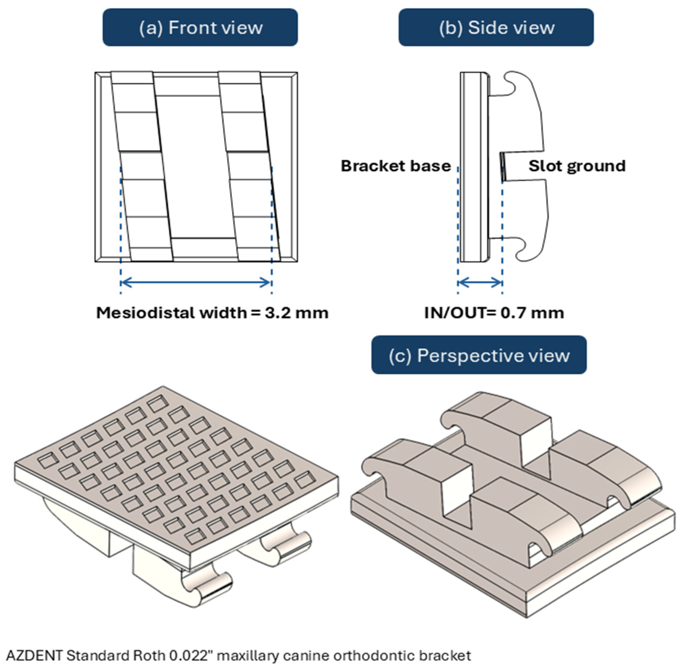
The orthodontic bracket is a small but geometrically demanding component. As illustrated in Figure 3, it presents two functionally distinct sides. The base is the side bonded to the tooth, which carries a mesh pattern designed to maximize mechanical interlocking with the adhesive resin, anchoring the bracket reliably to the enamel surface throughout treatment. The opposing side is the functional active side, where all the features exist. The most critical of these is the slot: a precisely dimensioned rectangular channel, standardized at 0.022 inch (approximately 0.559 mm), into which the archwire is engaged [27]. The remaining features on the functional face are the tie wings, which serve to hold the elastic ligatures or metallic ties that secure the archwire within the slot.
The slot is where all orthodontic mechanics happen; tip, torque, and rotation are all transmitted from the archwire to the tooth through this single feature. Its dimensional accuracy determines the precision of force transmission, and accordingly, the accuracy of tooth movement. Any deviation from the intended slot geometry introduces torsional play: a gap between the archwire and the slot wall. The torque is lost before it ever reaches the tooth. Multiple studies have identified dimensional inconsistencies in commercially available orthodontic brackets, with slot heights exceeding nominal specifications by 12–24%. Additionally, most evaluated brackets exhibited divergent slot walls rather than the intended parallel geometry [28,29]. The consequences are direct: incomplete torque transmission, increased treatment duration, and the need for compensatory clinical adjustments that would be unnecessary if the bracket had been manufactured to tolerance.
Figure 3.
Orthodontic bracket geometry showing the slot, tie wings, and base surface AZDENT Standard Roth 0.022″ maxillary canine orthodontic bracket with hook: (a) perspective view, (b) front view, and (c) side view. Mesiodistal width and in/out dimensions based on manufacturer specifications. Adapted from Ref. [30].
3.2.2. The Oral Environment and Its Demands on the Bracket
A bracket is not used in a controlled environment; it lives in the patient mouth for 18 to 36 months, and the oral environment is an unforgiving host. Saliva pH fluctuates continuously, dropping to as low as 2 in the presence of acidic foods and rising to 8.5 with alkaline mouthwashes [31]. Fluoride ions from toothpastes are particularly aggressive toward metallic alloys and can accelerate surface corrosion. Temperature cycling from hot and cold adds thermomechanical stress, while the constant presence of moisture creates an electrolytic environment that drives electrochemical degradation around the clock. Fróis et al. described the oral cavity plainly as “the ultimate corrosion-promoting environment for any metallic material” [32].
The clinical consequences of corrosion extend beyond the bracket itself. For stainless steel brackets, as the surface degrades, metal ions, primarily nickel, chromium, and iron, leach into the surrounding tissues. Nickel release, the most clinically significant, is associated with hypersensitivity reactions and gingival overgrowth [33]. Surface degradation also increases roughness, which promotes plaque accumulation and raises frictional resistance at the bracket–archwire interface, both of which compound the clinical burden. The bracket’s surface quality is therefore not an aesthetic consideration but a functional and biological one. Furthermore, internal porosity within the bracket body provides initiation sites for crevice corrosion, where localized electrochemical conditions within a pore are far more aggressive than at the exposed surface [34].
Alongside corrosion, the bracket must withstand the mechanical wear generated by the relative motion between the archwire and the slot walls during sliding. This is a continuous, low-magnitude abrasive process that acts over months. Regis et al. found that clinical use increased the force required for archwire sliding by 10–20%, primarily due to wear, corrosion, and deformation of the slot edges [35]. The bracket’s mechanical strength must be sufficient to maintain slot geometry and surface integrity across this entire service period [36].
4. Manufacturing Capability of SLM and MIM
This section reviews the materials and manufacturing routes employed in SLM and MIM orthodontic bracket production. The two processes are evaluated in terms of their manufacturing sequences, powder characteristics, and process parameter behavior. The investigation connects manufacturing philosophy to practical outcomes and process stability. A structured framework is also introduced to interpret SLM parameters as an interconnected system of inputs, behaviors, phenomena, and outcomes.
4.1. Manufacturing Philosophy
SLM and MIM are two different manufacturing processes that follow different philosophies. Both have notably shaped the production of metal orthodontic brackets. While each can produce small and geometrically complex metal parts, they carry different strengths and limitations when applied to orthodontic bracket manufacturing [37]. These differences define the clinical and commercial boundaries of what each process can and cannot deliver.
4.1.1. The SLM Manufacturing Sequence
SLM is a powder bed fusion additive manufacturing process in which a high-power laser melts fine metal powder, layer by layer, to build a high-density three-dimensional parts directly from a digital model [38]. For orthodontic brackets, the process begins with intraoral scanning or CT imaging of the patient’s dentition, which enables the bracket base to be designed to fit precisely to the individual tooth enamel [39]. The digital model is then sliced into thin cross-sections with thickness in µm and then imported into the build software, where the parameters governing the entire build are defined: part orientation, support structures, scan strategy, and layer thickness.
Once the build begins, a recoater spreads a thin, uniform layer of metal powder across the build platform. The laser scans the designated cross-sectional areas, fully melting the powder and fusing it to the layer below. The platform then descends by one layer thickness, a fresh layer of powder is deposited, and the cycle repeats layer by layer until the part is complete [40]. Figure 4 presents a schematic of a typical PBF machine, highlighting its main elements [19]. The entire build takes place inside a sealed chamber filled with inert shielding gas that protects the melt pool from oxidation. At the end, the part is removed from the powder bed and moves into post-processing: heat treatment to address residual stresses, support structure removal, and surface finishing [41].
Figure 4.
Schematic of a typical PBF machine—Reprinted from Ref. [19].
4.1.2. The MIM Manufacturing Sequence
MIM is a powder metallurgy process that borrows the idea of geometric flexibility from plastic injection molding and delivers it in a high-density sintered metal part [42]. It starts with feedstock preparation: fine metal powder, with particle sizes typically in the 10–20 µm range, is blended with a binder system of wax or thermoplastic resins at approximately 60:40 by volume [7]. The result is a homogeneous, injectable feedstock.
The feedstock is then injected under pressure into a precision-machined metal mold that is designed according to the final bracket geometry but deliberately oversized by approximately 17–22%, stable for a given feedstock, to compensate for the shrinkage that occurs during sintering [7]. This percentage range reflects variation across different feedstocks and sintering conditions; for a given feedstock, shrinkage magnitude is stable and predictable. As shown in Figure 3, MIM’s suitability for complex-geometry components requires a costly precision mold; however, this cost is distributed over the very high production quantities MIM is designed for, making the per-part cost favorable and explaining MIM’s continued dominance for orthodontic bracket manufacturing [37].
The part that comes out of the mold at this stage, known as the green part, holds its shape but is structurally fragile, held together more by the binder than by the metal itself. The binder is then removed in a debinding stage, either by solvent extraction or thermal decomposition, leaving behind a porous brown part of almost pure metal powder. That brown part goes into a high-temperature sintering furnace under a controlled atmosphere, where the metal particles fuse, and it contracts to its final dimensions with high relative density. The process cycle is illustrated in Figure 5 [37]. A third debinding route, catalytic debinding, is used in POM-based feedstocks such as BASF’s Catamold system, which is widely referenced in the orthodontic bracket MIM literature cited in this review (Section 4.2.2). In this route, the binder is decomposed by gaseous nitric acid at approximately 110 to 120 °C rather than by solvent or thermal means alone [43]. Figure 5 includes this as an alternative debinding route. Post-sintering, the bracket may undergo surface finishing operations such as polishing or electropolishing to achieve the required surface quality for clinically accepted orthodontic brackets [44,45].
Figure 5.
Workflow of metal injection molding—Adapted from Ref. [37].
4.1.3. Two Processes, Different Philosophies
Despite both achieving the clinical and mechanical requirements, SLM and MIM represent fundamentally opposing manufacturing philosophies. Each process is optimized for a different purpose; the characteristics that provide an advantage in one process can represent limitations in the other.
SLM: Customization Philosophy—Patient-Specific by Design
The defining philosophy of additive manufacturing is digital-to-physical freedom. Because SLM requires no mold, no tooling, and no fixed geometry, each part can be individually customized without requiring a dedicated mold or manufacturing complexity [41]. For orthodontic brackets, this principle translates directly into a patient-specific product. The bracket base side mirrors the anatomical contour of each individual tooth surface captured using appropriate acquisition tools [39]. Slot angles, base morphology, wing geometry, and overall bracket architecture can all be digitally tailored to the patient’s anatomy.
SLM answers directly to the core requirement of personalized medicine, not to the mass production of a standardized solution. In this sense, the process is not simply a manufacturing method but a philosophy: one that places patient individuality at the center of the production workflow.
The manufacturing flexibility offered by SLM comes at a cost. The process is highly sensitive to various parameters that require careful optimization for each specific material and geometry (as discussed in Section 4.3). While the lack of fixed tooling is SLM’s greatest clinical advantage, it also represents its most significant commercial limitation; it is not suitable for the mass-production needs of the standard orthodontic market [46].
MIM: Mass Production Philosophy—Consistency at Scale
The defining characteristic of MIM is its ability to produce geometrically complex parts at high production volumes and with favorable economics for small, intricate components with a typical maximum dimension of less than 60 mm [37,47]. MIM is similarly constrained by part mass, with economic and quality considerations generally favoring components below approximately 100 g, though larger parts can be produced with additional process caution [42]. Orthodontic brackets, typically well under 1 g, fall comfortably within this envelope, making MIM suitable from a size and mass standpoint.
As a result, MIM is well suited to orthodontic bracket mass production, where thousands of identical parts are produced from a single mold [7]. Once the mold is designed and validated, MIM can reproduce the same bracket geometry with high dimensional repeatability across entire production runs, with minimal per-part material waste, since runners and sprues can be recycled and reused [7,45].
This is the logic of industrial manufacturing: predictability, scalability, and cost efficiency. For the vast majority of orthodontic cases, where standardized bracket prescriptions are clinically sufficient, MIM delivers an excellent product at a price point that makes orthodontic treatment accessible at scale. The process requires no per-part digital preparation, no build parameter optimization, and no layer-by-layer monitoring; once the mold is set, production is largely automated.
Yet MIM’s strength is also its boundary. The mold is fixed—and with it, the geometry. Every bracket produced from a given mold is identical. There is no mechanism within MIM to accommodate patient-specific anatomy, individualized slot positioning, or case-specific morphology without redesigning and retooling the mold entirely. In an era of personalized medicine, where clinical evidence increasingly supports the value of patient-specific appliances, MIM’s reliance on fixed tooling represents a limitation that requires mold redesign and retooling to accommodate changes in bracket geometry [39,46].
4.2. Powder Characterization
Although SLM and MIM use powders differently, both processes depend strongly on powder quality. Particle size, shape, distribution, purity, and flow behavior all influence process stability and the quality of the final part. For this reason, powder selection is more than just choosing a material; it is one of the main factors that determine density, dimensional accuracy, mechanical properties, and defect formation.
4.2.1. SLM Powder Requirements
SLM requires highly spherical, gas-atomized powders with better flowability to ensure uniform spreading across the powder bed. The average size of the particles is between 15 and 53 µm, with the median sizes being about 20 and 40 µm [48]. Sphericity is critical because irregular particles reduce flowability and packing quality. Brika et al. showed that highly spherical powders with only a small proportion of very fine particles improved flowability and produced parts with better mechanical and geometric properties [49]. Likewise, Kiani et al. found that particle aspect ratio strongly influences the initiation of powder flow, while average particle size affects how easily that flow can be maintained [50]. These studies indicate that powder morphology is one of the main factors controlling powder bed quality in SLM.
Finer powders can improve density and mechanical properties. Chen et al. found that fine powder, with an average size of approximately 16 µm, produced SLM 316L parts with the highest tensile strength, yield strength, and relative density of 97.9% [51]. However, finer powder is not always beneficial. Du et al. reported that excessive amounts of fine powder can reduce density because oxide films form more easily during cooling, while powders with high oxygen content increase the risk of cracking along these oxide layers [48]. This means that powder size distribution must be carefully balanced because both very fine and very coarse powders can negatively affect the final part.
The choice of atomizing gas can also influence the final microstructure and performance of SLM parts. Dobson et al. showed that argon-atomized 17-4 PH powders produced a mainly martensitic microstructure, whereas nitrogen-atomized powders produced a more austenitic structure. After heat treatment, only the argon-atomized powders met the mechanical properties requirements [52]. This shows that atomization conditions affect not only powder production, but also the final metallurgical behavior of the printed material.
4.2.2. MIM Powder Requirements
MIM uses much finer powders than SLM, typically below 20 µm and often within the 2–15 µm range, because the powder must be mixed with a polymer binder to form an injectable feedstock. The powder does not need to be as spherical as in SLM, which is why both gas-atomized spherical powders and water-atomized irregular powders are commonly used. Gas-atomized and water-atomized 17-4PH powders also differ in achievable density: Gülsoy et al. found that gas-atomized powder could be sintered to a higher relative density (98.7% of theoretical) than water-atomized powder (97.08%), attributing the difference to the more regular particle morphology and higher packing efficiency of the gas-atomized powder [53]. Despite this density trade-off, water-atomized powder remains widely used commercially owing to its lower cost. Atomization atmosphere is a further consideration independent of atomization route. Dobson et al. showed that argon- versus nitrogen-atomized 17-4PH powder produces different phase compositions (martensitic vs. austenitic) due to interstitial nitrogen pickup during solidification [52]; because nitrogen is a known austenite stabilizer at the alloying level, this compositional effect is expected to persist through MIM debinding and sintering as well, not only in SLM’s rapid-solidification context.
Miura and Takamori noted an important trade-off between these two morphologies: spherical powders provide much better feedstock flowability, while irregular powders offer greater resistance to deformation during debinding [54]. Similarly, Hausnerova et al. found that even small differences in the 10–20 µm particle size fraction of water-atomized 17-4 PH powder had a significant effect on viscosity, injection pressure, and final sintered density [55]. This means that powder size and morphology are critical in MIM because they directly influence both feedstock behavior and dimensional stability during processing.
For orthodontic brackets, the most common MIM material is 17-4 PH stainless steel. Several studies used BASF Catamold 17-4 PH powder–binder mixture, which is a commercial ready-to-mold feedstock developed specifically for MIM applications [56]. Suharno et al. found that a powder loading of 64 vol% SS 17-4 PH provided the best balance between viscosity, torque, and shape stability for orthodontic brackets [57]. Likewise, Supriadi et al. developed local binder systems based on beeswax, paraffin wax, LLDPE, EVA, and stearic acid combined with 17-4 PH powder at 60 vol% loading [58]. These studies show that feedstock formulation is one of the main factors controlling moldability in MIM brackets.
Seensattayawong et al. compared 17-4 PH powders with particle sizes of 2.82, 4.04, and 12.65 µm in MIM feedstocks and achieved relative densities above 98% across all three sizes. The more intriguing finding was in the properties: finer powders produced better corrosion resistance, while coarser powders delivered higher elongation [59]. Particle size in MIM is therefore not simply a processing variable; it is a design choice that determines the final balance between corrosion performance and ductility.
4.2.3. Metallic Materials for Orthodontic Brackets
Both MIM and SLM use the same families of alloys that are related to biomedical applications: stainless steel, Co-Cr, and Ti alloys. However, stainless steel remains the dominant alloy for MIM orthodontic brackets, particularly austenitic 316L and precipitation-hardened 17-4 PH grades. In SLM, the emphasis is different: Co-Cr and titanium alloys receive greater attention, as their superior biocompatibility and corrosion resistance make them more suitable for long-term intraoral applications [8].
The biological performance difference between these alloys is not marginal. Ortiz et al. compared three orthodontic alloys and found that titanium brackets demonstrated the best biocompatibility, while stainless steel released the highest amount of metal ions among the investigated materials [9]. Metal ion release from stainless steel, primarily nickel, chromium, and iron, is associated with hypersensitivity reactions and gingival inflammation. This suggests that although stainless steel remains the most common bracket material, titanium offers important advantages in long-term biological performance.
For SLM-manufactured brackets specifically, Co-Cr alloys represent the most clinically promising material choice, combining the manufacturing advantages of SLM with better corrosion resistance and biocompatibility than stainless steel, while remaining more accessible and better characterized for dental applications than titanium alloys [60,61]. This is the material rationale behind the selection of Co-Cr for the SLM bracket manufacturing framework proposed in this review.
Biocompatibility differences between SLM and MIM brackets arise not only from alloy selection but from process-induced microstructural effects on a shared alloy. In SLM, atomization gas choice alters phase composition (martensitic vs. austenitic 17-4PH [52]), which is known to affect corrosion resistance in stainless steels. In MIM, incomplete debinding-related residual carbon promotes chromium carbide precipitation at grain boundaries, depleting local chromium and reducing corrosion resistance [62,63], a mechanism distinct from, but compounding, the crevice corrosion risk already associated with MIM’s interconnected porosity (Section 5.1). This indicates that biocompatibility is not guaranteed by alloy choice alone but depends on how well each process controls microstructural purity.
4.3. Parameter Nature
Manipulating the parameters to the optimal level is the key to managing any manufacturing process. For the sake of optimization, in this section of the review, the parameters of SLM and MIM are represented from a different point of view. This section introduces a cluster-based framework for understanding SLM process parameters, treating inputs, behaviors, phenomena, and outcomes as an interconnected system rather than as independent variables, in contrast to the stage-dependent MIM parameters.
4.3.1. Parameter Nature of the MIM Process
In MIM, the manufacturing process is more numerically predictable because the main process stages are sequential and relatively independent from one another [64,65]. A typical MIM process consists of four main steps: feedstock preparation, injection molding, debinding, and sintering. Each stage has its own parameters, such as injection speed, injection temperature, injection pressure, debinding temperature, and sintering time. Since these parameters can often be optimized separately, the overall process is easier to control and reproduce. In addition, the thermal conditions during debinding and sintering are generally more homogeneous throughout the component, which helps reduce variations in shrinkage; the evidence for this is straightforward: sintering shrinkage is predicted and compensated for before the mold is ever made. In contrast to SLM, MIM parameters are weakly coupled, which allows them to be analyzed in isolation.
4.3.2. Parameter Nature of the SLM Process
A common limitation in existing SLM literature is the presentation of process parameters as discrete, independently acting variables. In practice, the approach is misleading [19]. The SLM process is better understood as a clustered system, where groups of inputs, behaviors, and phenomena act collectively to produce a given set of outcomes. This process-parameter-oriented view is also reflected in recent literature in Metal Additive Manufacturing, chapter 1, where PBF process parameters are presented in relation to their effects on print quality and manufacturing performance [66]. To convey these concepts accurately, the present review distinguishes between five specific terms that are often used interchangeably in literature but carry distinct meanings in this context: process elements, inputs, behaviors, phenomena, and outcomes. Establishing this distinction is essential for a meaningful discussion of parameter manipulation.
Process elements are the physical and mechanical components that form the SLM machine and its operating environment. These include the laser source, the optical system, the build platform, the powder spreader, the atmosphere system, the powder material itself, and the model geometry. These elements define the structural boundaries within which the process operates. Figure 6 is a flow chart displaying the process elements.
Figure 6.
SLM Process elements—Newly prepared.
The full set of SLM parameters can be organized into three functional categories, each with a distinct role in determining process outcomes.
The first category, “inputs,” consists of variables that can be controlled by the operator, either through machine software or external software, prior to the build. They represent the primary means by which the operator interacts with and steers the process. Inputs are further subdivided by their source: machine software and external software each govern a distinct set of operational variables, as illustrated in Figure 7. Inputs are the levers of control.
Figure 7.
Classification of SLM process inputs according to their source, distinguishing between machine-controlled parameters and externally defined process settings—Newly prepared.
The second category of parameters is “behaviors,” which encompasses the physical responses that develop within the process as inputs interact with the powder and the build environment. Unlike inputs, behaviors are not directly set; they are observed consequences. Their importance lies in the fact that they mediate the relationship between inputs and outcomes. Critically, behaviors do not act in isolation; each behavior influences subsequent behaviors, creating a cascade of interdependent responses throughout the build. The range of behaviors triggered by process inputs, along with their downstream effects, is systematically presented in Table 1.
Table 1.
SLM parameter cluster system: inputs, in-process behaviors, and manufacturing outcomes.
Figure 8 represents an example of the proposed cluster-based framework, illustrating how multiple processing and geometrical factors interact through melt pool dynamics, thermal gradients, cooling behavior, and heat accumulation, ultimately governing residual stress generation as a central process behavior.
Figure 8.
Cluster-based schematic of the SLM process showing the cause–effect relationships between process inputs, in-process behaviors (residual stress generation), induced phenomena, and resulting outcomes such as geometrical distortion, and dimensional deviation, mechanical response—Newly prepared.
As illustrated in Table 1, the melt pool serves as a representative example of this behavioral interdependency. It is simultaneously driven by multiple inputs, such as laser power, scan speed, and hatch spacing, and is itself a driver of subsequent behaviors, including cooling rate, solidification rate, and interlayer bonding. Each of these behaviors, in turn, propagates further along the chain, eventually determining outcomes such as porosity, surface roughness, and dimensional deviation. The melt pool does not act alone, nor is it acted upon in isolation; it sits at the center of a network of mutually influencing behaviors. The remaining entries in Table 1 demonstrate that this same multi-directional interdependency applies across all documented behaviors in the SLM process.
The third category of parameters, machine limits, represents the operational ceiling of the process. These are not variables to be optimized but constraints that define the boundaries of what is achievable on a given machine. Machine limits are determined by three factors: the machine’s hardware specifications (e.g., maximum laser power, minimum achievable layer thickness, and build volume); the machine’s current physical condition; and its calibration accuracy. No combination of inputs can produce outcomes that exceed what the machine is physically capable of delivering. Operators must therefore understand machine limits as a fixed framework within which optimization input must occur.
Phenomena are physical occurrences that are inherent to the SLM process and cannot be entirely eliminated. What distinguishes a well-optimized SLM process from a poorly controlled one is not the absence of these phenomena, but the degree to which their effects are managed. Residual stress generation, for instance, is an inevitable consequence of rapid thermal cycling; however, its magnitude can be reduced through a group of inputs: preheating the build platform, optimizing scan strategy, and managing thermal gradients through part orientation. Similarly, balling tendency, the formation of spherical melt pools that fail to wet the underlying surface, is promoted by poor wetting behavior arising from high oxygen content, excessive scan speed, or inadequate laser power. By addressing the inputs that drive the relevant behaviors, the operator can reduce the severity of balling without eliminating the underlying thermodynamic condition that makes it possible. However, careful input selection can define the magnitude of each phenomenon and its impact on the final part.
This distinction between phenomena as a category and outcomes as a different category is important for interpreting the results presented in Section 5. Outcomes are the measurable properties of the final printed part that result from the cumulative effect of inputs, behaviors, and phenomena acting together. In the context of SLM-manufactured orthodontic brackets, the outcomes of primary interest are porosity and relative density, surface roughness, dimensional accuracy, mechanical strength, and distortion.
In summary, understanding the SLM process requires more than cataloging its variables in isolation; the parameters governing SLM form an interconnected system in which every variable influences and is influenced by others. This inherent complexity is precisely what makes SLM outcomes harder to predict than those of MIM, where process variables are fewer, more stable, and largely governed by fixed tooling. Rather than being a limitation, however, this complexity is also the source of SLM’s adaptability. The same framework that makes outcomes sensitive to change is what enables the high degree of customization that MIM cannot provide. This distinction provides the conceptual basis for the comparative analysis presented in the sections that follow.
5. Manufacturing Outcomes and Discussion
The differences between SLM and MIM become most visible in the final properties of the manufactured bracket. Although both processes can produce clinically acceptable parts, they do so through very different routes, which leads to differences in density, porosity, dimensional deviation, geometrical distortion, surface quality, and post-processing requirements. Examining these outcomes is important because they directly affect the accuracy, durability, and long-term clinical performance of the bracket.
5.1. Porosity and Density
Porosity and density are not two independent properties; they are inverse expressions of the same concept: the material fraction of the part versus the void. Both characteristics affect the performance and quality of orthodontic brackets. For SLM, the most directly relevant study is Yang et al., who fabricated customized orthodontic brackets from 316L stainless steel and achieved a density greater than 99% after optimizing the scanning parameters and applying a laser remelting pass [5,67]. Similar results have been reported for another SLM alloy, Co-Cr-Mo, where a density of 99.468% can be achieved when the process is properly optimized [68]. The influence of laser power, scan speed, and hatch spacing on porosity in dental Co-Cr alloy was investigated by systematically varying these parameters during the SLM process, confirming that volumetric energy density governs the transition between lack-of-fusion porosity and keyhole porosity, with minimum porosity achieved at mid-range optimized combinations [69]. This shows that SLM can produce near-full-density parts, but only when the energy input is carefully controlled. It is also important to note that when poorly optimized, SLM produces isolated spherical keyhole pores, a fundamentally different porosity type from MIM.
MIM brackets show a different behavior because porosity is much more difficult to eliminate completely. The porosity type in MIM is interconnected, arising from the binder removal stage, a structural characteristic that allows electrolyte penetration and creates initiation sites for crevice corrosion in the oral environment. Abdulah et al. studied MIM 17-4 PH stainless steel at different sintering temperatures and found relative densities ranging from approximately 86% at 1200 °C to 91.5% at 1300 °C, with porosity levels between 5% and 12% [70]. Suharno et al. also reported that density increased with sintering temperature, with the best hardness obtained at 1360 °C [56]. During the MIM thermal cycle, porosity increases gradually during the debinding stage as the binder is removed, followed by rapid densification during sintering, where the component reaches a final relative density of approximately 95–97% [71]. These studies confirm that MIM density can be improved through higher sintering temperatures. Sung et al. demonstrated this most directly, showing MIM 17-4PH density increasing from approximately 61% at 900 °C to 99% at 1350 °C through sintering temperature control alone, without HIP or other additional densification treatment [72]. This result indicates that much of the density gap between as-sintered MIM and SLM can be narrowed through sintering-parameter control alone.
Direct comparisons between SLM and MIM further highlight this difference. Hamidi et al. compared 316L stainless steel parts produced by both methods and found that SLM resulted in 29% higher tensile strength and 62% greater elongation at fracture. The authors attributed this difference mainly to the higher porosity present in the MIM samples [73]. Similarly, Suwanpreecha et al. compared SLM and MIM for a beta titanium alloy and found that SLM produced high-density components, whereas MIM showed lower ductility because of carbon contamination from the binder and the formation of Ti2C [74]. Overall, the literature consistently shows that SLM has a clear advantage over MIM in achieving high density and low porosity.
5.2. Dimensional Deviation and Shrinkage
Dimensional deviation is the difference between the designed dimensions and the actual measured dimensions of the final part. Shrinkage behaves very differently in SLM and MIM. In SLM, dimensional changes are relatively small because the part is built close to its final geometry. Yang et al. achieved orthodontic bracket slot errors of less than 10 µm after optimizing the process parameters [5]. Dimensional deviation in SLM is primarily driven by thermal gradient-induced solidification shrinkage, where laser power, scan speed, and layer thickness collectively govern the value and distribution of this shrinkage across the produced component [75,76]. Z-direction deviations in optimized SLM parts are typically within ±0.8% [77], which, for a 0.559 mm bracket slot translates to a maximum deviation of approximately ±4.5 µm, well within the clinically acceptable range when parameters are properly controlled.
MIM behaves differently because shrinkage occurs during sintering. When the binder is removed, porosity is created inside the part, and the subsequent sintering stage causes the structure to densify and contract; this dimensional transformation during sintering is illustrated in Figure 9 [78]. Supriadi et al. showed that this shrinkage is not uniform across orthodontic bracket geometry. The bracket wings shrank by approximately 11% along the x-axis but elongated by about 6.6% along the y-axis, while the trunk shrank by around 7.2% along the x-axis and 5% along the y-axis. Corners also shrank more than flat surfaces, which rounded features that were originally square [79], which compromise the engagement between the slot and the archwire. Šarić found that most shrinkage variation comes from density differences within the green part, while holding pressure and coolant temperature have the strongest influence on the final shrinkage behavior [80]. This non-uniformity is the central dimensional challenge in MIM bracket manufacturing; it cannot be eliminated, only compensated for at the mold design stage.
Figure 9.
Dimensional changes between the green and final sintered MIM component—Reprinted from Ref. [78].
When the two processes are compared directly, SLM undergoes minimal dimensional deviation, primarily arising from solidification shrinkage and thermal gradients, while MIM undergoes non-uniform sintering shrinkage in the range of 17–22% [1,7,10]. Because of this, MIM requires careful compensation during mold design to account for the dimensional changes that occur during sintering. In SLM, after the operator reaches parameter stability and achieves repeatability, uniform dimensional change can be compensated for directly in the digital model. Non-uniform solidification shrinkage, on the other hand, is harder to compensate for.
5.3. Geometrical Distortion
Geometrical distortion is the macroscopic warping, bending, or twisting of the part; When residual stress accumulates and exceeds the material’s yield strength, the part physically deforms. It is a different outcome from dimensional deviation (Section 5.2). Both may share common root causes, but both require different solutions. A part can have dimensional deviation without visible distortion, like a slot that is slightly undersized due to localized shrinkage but is not warped. Conversely, a part can be distorted without all dimensions deviating uniformly. These two conditions therefore affect bracket function differently.
In SLM, the distortion mechanism follows a clear sequence: a thermal gradient causes residual stress, which in turn leads to geometrical distortion. Residual stress is a central SLM issue; its primary cause is the thermally induced stress generated during rapid non-uniform expansion and contraction across heating and cooling cycles. Different regions of the part experience different temperatures simultaneously; the newly melted layer is extremely hot while the layers below are cooler, and this temperature difference creates the thermal gradient that drives residual stress generation throughout the build [81,82]. The parameters that directly influence residual stress, and therefore distortion, are scan strategy, build orientation, support placement, layer thickness, laser power, scan speed, and hatch spacing. It has been noted that residual stresses are more pronounced in non-porous parts compared to porous ones, since pores act as stress-relief sites within the bulk material, creating an inherent tension in SLM optimization between maximizing density and minimizing distortion [68,75,83].
Geometrical distortion in SLM could be controlled at two stages: during the printing process by manipulating the parameters (Section 4.3.2) and during post-processing, which is explained more broadly in Section 5.6.1.
In MIM, the dominant distortion mechanism is not residual stress in the SLM sense but shrinkage during sintering. The main source is feedstock inhomogeneity in the green part, induced during injection molding, which leads to shrinkage variations during sintering. In an orthodontic bracket geometry study, this non-uniformity was clearly demonstrated; shrinkage was not consistent across the wing, trunk, and base of the bracket [79,80]. MIM’s slow, near-equilibrium sintering is understood to produce much lower residual stress than SLM’s rapid solidification. The recommended protocol to solve this obstacle is uniform feedstock packing and controlled sintering conditions.
Geometrical distortion is particularly critical in orthodontic brackets because it directly threatens slot geometry precision. A distorted slot cannot accurately transmit the prescribed tooth movements, tip, torque, and rotation, which limits the bracket’s function and, especially in the case of SLM-manufactured customized brackets, compromises the overall value of patient-specific design.
5.4. Wear Resistance
Tensile strength and other bulk mechanical properties are not the limiting factor for any of the material classes used in this application. Table 2 shows SLM 316L reaching approximately 612 MPa compared with approximately 410 MPa for MIM 316L [51,73], and both values exceed the forces a bracket experiences clinically by a wide margin. Şaylan and Özel measured yield points between 212 and 549 N and ultimate strength up to 765 N for commercial metal brackets under compressive loading representative of clinical rebonding [84], while Elabed et al. report that customized 3D-printed brackets withstand torque up to 60 N·mm, above the accepted clinical threshold [36]. Even ceramic and, in suitable formulations, polymer brackets can successfully withstand orthodontic forces; Zinelis and Brantley note that ceramic brackets are not limited by load-bearing capacity but rather by low fracture toughness and increased friction at the bracket-archwire interface [85]. Bulk strength is therefore unlikely to differentiate SLM and MIM brackets in practice; what is of genuine concern, across material classes, is wearability.
The archwire and slot walls remain in continuous sliding contact throughout treatment, and Regis et al. found that clinical use increases the force required for archwire sliding by 10–20%, attributed to wear, corrosion, and deformation of the slot edges [35]. Wear behavior, not bulk strength, is what changes measurably over the bracket’s service life.
Direct comparisons between the two processes support a wear advantage for SLM. Ziębowicz et al. compared Co-based, low-carbon alloys produced by Selective Laser Sintering and Powder Injection Molding and found superior abrasive wear resistance in the SLS-processed alloy, attributed to a hard intermetallic phase precipitated as fine, evenly distributed particles within the cobalt matrix [86]. This is consistent with a broader pattern reported for laser powder bed fusion alloys, where finer grain size and higher hardness relative to conventionally processed alloys correspond to higher wear resistance and lower coefficient of friction [87].
Where wear resistance is a concern for either process, the same surface finishing discussed in Section 5.5 offers a practical route to improvement. Roughness and wear are mechanistically linked, so the post-processing steps shown to reduce surface roughness for both SLM and MIM are also expected to reduce the surface area available for abrasive wear initiation.
5.5. Surface Roughness
The surface finish of an orthodontic bracket is not only an aesthetic matter. It also affects friction during tooth movement, plaque accumulation, wear behavior, and overall clinical performance. The mechanisms responsible for surface roughness differ between SLM and MIM, leading to different surface-quality limitations and post-processing requirements.
5.5.1. Surface Roughness of SLM Brackets
As-built SLM parts generally have rough surfaces because of the layer-by-layer melting process, the adhesion of partially melted powder particles, and the staircase effect that appears on inclined surfaces.
Dong et al. found that even after parameter optimization, the best achievable roughness for SLM 316L stainless steel remained around Ra 5.0 µm on top surfaces and 8.0 µm on vertical surfaces [88]. Scanning speed had the greatest influence on roughness, followed by laser power, while hatch spacing had the smallest effect [89]. Likewise, Vandenbroucke and Kruth achieved densities up to 99.98% for titanium parts produced by SLM but still identified surface roughness as one of the main limitations of the process [90]. This means that even when density is optimized, surface quality remains a challenge in SLM.
Build orientation also plays an important role. Milde et al. found that increasing the part orientation angle led to higher surface roughness in SLM 316L parts [91]. Yang et al. reported that optimized SLM parameters produced brackets with improved surface quality and mechanical performance, although the study focused more on density and dimensional accuracy than on reporting specific roughness values [5]. This suggests that part orientation and process parameters must be considered together when trying to control surface quality.
Post-processing can significantly improve the surface quality of SLM brackets. These studies show that post-processing is necessary if SLM brackets are expected to meet clinical surface quality requirements, which will be discussed in Section 5.5.
5.5.2. Surface Roughness of MIM Brackets
Surface roughness is particularly important for orthodontic brackets because rough surfaces increase friction and encourage bacterial adhesion. Suharno et al. specifically studied the surface quality and microstructure of MIM 17-4 PH stainless steel brackets and emphasized that brackets require smooth surfaces for proper clinical performance [92].
Supriadi et al. reported that investment-cast brackets had a surface roughness of approximately 0.91 µm, while commercial brackets reached 0.53 µm [79]. In general, MIM produces smoother surfaces than investment casting, although post-processing is still needed for orthodontic use. Friederici and Hartwig found that MIM titanium parts typically had as-sintered roughness values around Ra 2–3 µm. However, using finer powders with an average size of 15 µm and a polished mold reduced the roughness to below 1.2 µm [13]. This shows that both powder size and mold quality have a strong influence on the final surface finish of MIM parts.
Post-processing can improve MIM surface quality even further. Yang and Tsai showed that abrasive belt grinding of MIM 316L stainless steel reduced roughness to approximately Ra 0.097 µm. They explained that grinding smooths the surface by covering the small voids left after sintering through plastic flow; this finishing mechanism is expected to pose lower dimensional risk than more aggressive finishing methods [93]. Compared with MIM, as-built SLM parts usually start with much rougher surfaces, often around Ra 5–10 µm or higher. This gives MIM an advantage in orthodontic applications where low friction and reduced bacterial adhesion are important. However, after finishing, both SLM and MIM can reach sub-micron roughness values.
Table 2.
Comparison of outcomes between SLM and MIM.
Table 2 compares SLM and MIM across six manufacturing quality properties: relative density, porosity type, shrinkage, geometrical distortion tendency, surface roughness, and mechanical properties, together with the clinical implications and commercial evidence associated with each outcome for orthodontic bracket performance. These findings suggest a process-level trend, although the magnitude of the reported differences may also reflect confounding factors such as alloy composition, geometry, processing conditions, and post-processing.
5.6. Post-Processing
Neither SLM nor MIM produces a fully finished bracket directly after fabrication. Both require additional steps before the part reaches its final condition, although the type of post-processing is different in each case.
5.6.1. Post-Processing of SLM Brackets
SLM parts leave the build plate in a near-final state in terms of density, but they still contain residual stresses from the repeated heating and cooling cycles and usually have rough as-built surfaces. As a result, post-processing generally focuses on two areas: heat treatment and surface finishing.
Heat treatment is usually the first step because it reduces residual stress and improves the microstructure. Le et al. described the typical sequence for SLM Ti-6Al-4V as stress relieving, annealing, and solution treatment with aging [14]. These treatments reduce residual stress, lower porosity, and convert the brittle martensitic structure into a more ductile α+β structure, which improves fatigue performance. Similarly, Ko et al. found that SLM Co-Cr dental alloys contained higher residual stresses than cast alloys and recommended heat treatment at 950 °C or higher to improve ductility [103]. However, Htat et al. reported that stress-relief annealing reduced the marginal fit of SLM Co-Cr dental copings because of thermal distortion [104]. Heat treatment of SLM-produced SS316L resulted in notable improvements in mechanical properties, increasing tensile strength by 28% and microhardness by 22% [105]. Chao et al. further quantified the effect on residual stress, reporting a compressive residual stress of approximately 248 MPa in as-built SLM 316L, which was reduced by approximately 90% to around 25 MPa after heat treatment at 1100 °C for 5 min [106]. This suggests that heat treatment can improve mechanical performance, but it may also affect dimensional accuracy in some dental applications.
Hot Isostatic Pressing (HIP) is often used when internal porosity must be reduced. Jamshidi et al. showed that HIP substantially improved the ductility of SLM Ti-6Al-4V, especially in both vertical and horizontal build orientations [107]. Likewise, Rosenthal et al. found that HIP eliminated porosity in SLM AlSi10Mg and significantly increased elongation, although higher HIP temperatures reduced tensile strength [108]. Barbin et al. also reported that HIP improved the mechanical performance of Ti-6Al-4V dental prostheses by increasing screw removal torque and reducing strain in full-arch frameworks [109]. These studies show that HIP is one of the most effective post-processing methods for improving internal quality and ductility in SLM parts.
Surface finishing is equally important because SLM parts generally start with relatively high roughness values. Löber et al. compared grinding, sandblasting, electrolytic polishing, and plasma polishing for SLM 316L and found that simple geometries could be finished effectively, while complex shapes remained more difficult [15]. Similarly, Doche et al. developed an electropolishing process for SLM 316L that reduced roughness by approximately 90%, although maintaining dimensional accuracy at the same time remained difficult [110]. Fang et al. combined nanosecond laser processing with mechanical grinding and reduced the roughness of SLM 316L from approximately 7.9 µm to around 3 nm, while also removing oxide layers and microcracks [111]. For more practical multi-step finishing, Soja et al. found that a sequence of white oxide blasting, centrifugal finishing, and glass bead blasting achieved Ra values of approximately 0.6 µm on inclined stainless-steel surfaces [112]. Surface finishing is an essential quality for SLM parts that are expected to meet clinical requirements.
5.6.2. Post-Processing of MIM Brackets
MIM post-processing is an essential part of the total manufacturing cycle. Highly controlled debinding and sintering stages, which preceded post-processing, affect the outcome and streamline the process by avoiding the need for additional corrective steps. Incomplete debinding leaves residual carbon in the part. Bada et al. showed that excess carbon increases retained austenite and reduces the mechanical properties of 17-4 PH stainless steel [62]. As a result, carbon control is one of the most important aspects of MIM processing.
Density and mechanical strength are shaped in the sintering process. Sintering is usually carried out between 1250 and 1380 °C, and the atmosphere used during this stage can strongly affect the final density. Shieddieque et al. found that sintering 17-4 PH at 1360 °C in argon produced higher density than vacuum sintering at the same temperature because vacuum conditions promoted pore growth [113]. A well-controlled sintering stage helps avoid additional densification treatments and dimensional corrections, such as resizing, after sintering [72,79].
Powder particle size is a further variable affecting the mechanical properties achieved after sintering and heat treatment. Nakayama and Kyogoku reported that heat-treated martensitic stainless steel compacts produced from 5 μm powder reached a tensile strength of 1800 MPa with 12% elongation, compared with 1680 MPa and 10% elongation for compacts produced from 10 μm powder; in both cases, the properties were approximately equal to those of the wrought material [114].
Additional finishing steps may still be needed after sintering. MIM brackets can undergo age hardening, electropolishing, or surface grinding depending on the final requirements. Supriadi et al. also described the geometric distortion caused by sintering, which must be compensated for during mold design [79]. Unlike SLM, which starts with a nearfully dense part, MIM depends on a long sequence of chemical and thermal treatments before the final density and shape are achieved.
Figure 10 presents radar charts illustrating the manufacturing capabilities of the two processes and the effects of post-processing, particularly for SLM surface roughness, The scoring based on Table 2 evidence.
Figure 10.
Comparative SLM vs. MIM Capability Profile of Orthodontic Brackets Relative to Commercially Accepted Standards: (a) As-Built/As Sintered Capability Profile; (b) Post-Processed Capability Profile—Newly prepared.
Table 3 the scoring system is based primarily on data reported for 316L stainless steel, supplemented by studies that reported data for stainless steel without specifying the alloy grade.
Table 3.
Represents the scoring system of the radar chart Figure 10.
Dimensional accuracy: Alqahtani reported slot-dimensional deviations ranging from 12% to 24% across the metallic and ceramic bracket systems investigated, with a 20% deviation reported for the MIM GAC-Ovation bracket [28]. Therefore, 20% was used as the upper bound for the scoring scale for dimensional accuracy.
Surface roughness: The ideal value (score = 10) was set at 0.2 µm, based on the clinically acceptable roughness threshold [100], while the lower bound (score = 0) was set at 12 µm, corresponding to the highest reported as-built roughness for SLM brackets.
Geometrical stability: Direct comparison is limited by differences in how geometrical deviation is reported. The 17.7° deviation reported for post-processed Co-Cr SLM represents the angular deviation of the slot walls from parallelism, whereas MIM studies report slot-wall parallelism through deviations in the slot face and base dimensions. In addition, residual stress, which is a major cause of geometrical distortion in SLM, is reported in the SLM literature, whereas comparable residual-stress data are not available for the MIM studies considered here.
6. Limitations of the Study
A key limitation of this review is the scarcity of matched SLM-MIM comparisons involving actual orthodontic brackets. Of the 112 dated references, only 24 (21%) are bracket specific. The remaining evidence includes studies on general or analogous manufacturing processes, general orthodontic topics, or clinical-validation studies.
Another limitation is the difficulty of directly comparing SLM and MIM findings. Few studies compare the two processes using the same alloy, bracket geometry, manufacturing conditions, and specimen type. In addition, studies differ in their materials, measurement methods, and processing or post-processing conditions. For example, geometrical deviations are not always measured in the same way.
7. Conclusions
This review aimed to address the following objectives: comparing SLM and MIM as distinct manufacturing philosophies for orthodontic brackets, introducing a cluster-based framework for SLM process parameters, evaluating key manufacturing outcomes across both processes, and assessing the post-processing requirements of each.
- Selective Laser Melting (SLM) and Metal Injection Molding (MIM) represent complementary manufacturing approaches for metallic orthodontic brackets, each offering distinct advantages depending on production requirements and clinical applications. MIM is particularly suitable for standardized, high-volume production, whereas SLM provides greater flexibility for patient-specific bracket customization.
- This review introduced a cluster-based framework that reframes SLM process parameters as an interconnected system of inputs, behaviors, phenomena, and outcomes, rather than a disconnected list of independent variables. Under this framework, optimizing SLM is not a matter of finding one correct parameter setting but of identifying a stable, well-characterized input cluster that reliably delivers the desired outcome for a specific material and geometry.
- Neither process yields a clinically ready bracket directly from production. SLM requires heat treatment to address residual stress together with surface improvement after the build, while MIM requires surface finishing; both ultimately reach comparable final quality, shifting the meaningful distinction from as-built performance to the extent of post-processing required.
- Overall, the selection of an appropriate manufacturing technique should be guided by the intended clinical application, the required degree of customization, and the desired material and manufacturing characteristics. Integrating manufacturing considerations with patient-specific orthodontic requirements may contribute to improved bracket design and treatment efficiency.
Future research should experimentally evaluate the proposed cluster-based framework by varying groups of SLM input parameters together to investigate their combined effects on manufacturing outcomes for specific materials and geometries.
Author Contributions
E.E. Conceptualization, Methodology, Investigation, Formal Analysis, Visualization, Writing—Original Draft Preparation, Writing—Review and Editing. C.G. Methodology, Formal Analysis, Writing—Review and Editing, Supervision. A.Z. Investigation, Formal Analysis, Writing—Review and Editing, Supervision. I.E.-D. Conceptualization, Visualization, Writing—Review and Editing, Supervision. All authors have read and agreed to the published version of the manuscript.
Funding
The APC funded by Silesian University of Technology/Faculty of Mechanical Engineering, Department of Engi-neering Processes Automation and Integrated Manufacturing Systems.
Institutional Review Board Statement
Not applicable.
Informed Consent Statement
Not applicable.
Data Availability Statement
No new data were created or analyzed in this study. Data sharing is not applicable to this article.
Acknowledgments
During the preparation of this work, the authors used (OpenAI) and (Anthropic) to assist with language refinement, sentence restructuring, and brainstorming. The authors critically reviewed and edited all generated content and take full responsibility for the content of the published article.
Conflicts of Interest
The authors declare no conflicts of interest.
Abbreviations
The following abbreviations are used in this manuscript:
| SLM | Selective Laser Melting is a commonly used historical or commercial term. |
| PBF-LB/M | Laser powder bed fusion of metals is the ISO/ASTM standardized name for the exact same physical process that “SLM” |
| CAD | Computer-Aided Design |
| Co-Cr-Mo | Cobalt–Chromium–Molybdenum alloy |
| FEM | Finite Element Method |
| FEA | Finite Element Analysis |
| HIP | Hot Isostatic Pressing |
| PBF | Powder Bed Fusion |
| MIM | Metal Injection Molding |
| Ra | Arithmetic Average Roughness (surface roughness parameter) |
| Ti-6Al-4V | Titanium alloy (6% aluminum, 4% vanadium) |
| 17-4 PH | 17-4 Precipitation-Hardening stainless steel |
| 316L | Austenitic stainless steel (low carbon) |
References
- Eliades, T.; Zinelis, S.; Bourauel, C.; Eliades, G. Manufacturing of Orthodontic Brackets: A Review of Metallurgical Perspectives and Applications. Recent Pat. Mater. Sci. 2008, 1, 135–139. [Google Scholar] [CrossRef] [Scilit]
- Virdhian, S.; Jamilah, S.; Supriadi, S.; Suharno, B. Metal Injection Moulding Process Simulation for Orthodontic Bracket Application. J. Teknol. Bahan Barang Tek. 2017, 7, 51. [Google Scholar] [CrossRef] [Scilit]
- Graf, S.; Thakkar, D.; Hansa, I.; Pandian, S.M.; Adel, S.M. 3D Metal Printing in Orthodontics: Current Trends, Biomaterials, Workflows and Clinical Implications. Semin. Orthod. 2023, 29, 34–42. [Google Scholar] [CrossRef] [Scilit]
- Tsai, M.J.; Wu, C.T.; Chen, C.Y. Custom-made brackets fabrication by an additive manufacturing process for orthodontic treatment. Biomed. Eng. Appl. Basis Commun. 2011, 23, 493–500. [Google Scholar] [CrossRef] [Scilit]
- Yang, Y.; Bin Lu, J.; Luo, Z.Y.; Wang, D. Accuracy and density optimization in directly fabricating customized orthodontic production by selective laser melting. Rapid Prototyp. J. 2012, 18, 482–489. [Google Scholar] [CrossRef] [Scilit]
- Skidmore, K.J.; Brook, K.J.; Thomson, W.M.; Harding, W.J. Factors influencing treatment time in orthodontic patients. Am. J. Orthod. Dentofac. Orthop. 2006, 129, 230–238. [Google Scholar] [CrossRef] [Scilit] [PubMed]
- Zinelis, S.; Annousaki, O.; Makou, M.; Eliades, T. Metallurgical characterization of orthodontic brackets produced by Metal Injection Molding (MIM). Angle Orthod. 2005, 75, 1024–1031. [Google Scholar] [CrossRef] [Scilit]
- Şaylan, Ç.E. Narrative Review on Materials and Manufacturing Techniques of Metal Brackets. Open Dent. J. 2025, 19, e18742106406819. [Google Scholar] [CrossRef] [Scilit]
- Ortiz, A.J.; Fernández, E.; Vicente, A.; Calvo, J.L.; Ortiz, C. Metallic ions released from stainless steel, nickel-free, and titanium orthodontic alloys: Toxicity and DNA damage. Am. J. Orthod. Dentofac. Orthop. 2011, 140, e115–e122. [Google Scholar] [CrossRef] [Scilit] [PubMed]
- Miura, H.; Osada, T.; Itoh, Y. Metal Injection Molding (MIM) Processing. In Advances in Metallic Biomaterials; Springer: Berlin/Heidelberg, Germany, 2015; pp. 27–56. [Google Scholar] [CrossRef] [Scilit]
- Basir, A.; Sulong, A.B.; Jamadon, N.H.; Muhamad, N. Physical Properties of Sintered Stainless Steel 17-4PH Micro-Part Processed by Micro-Powder Injection Molding. J. Kejuruter. 2022, 34, 1209–1214. [Google Scholar] [CrossRef] [Scilit] [PubMed]
- Singh, G.; Missiaen, J.M.; Bouvard, D.; Chaix, J.M. Additive manufacturing of 17–4 PH steel using metal injection molding feedstock: Analysis of 3D extrusion printing, debinding and sintering. Addit. Manuf. 2021, 47, 102287. [Google Scholar] [CrossRef] [Scilit]
- Friederici, V.; Hartwig, T. Metal injection Moulding of titanium medical components. Key Eng. Mater. 2016, 704, 155–160. [Google Scholar] [CrossRef] [Scilit]
- Le, A.T.; Dau, V.H.; Hoang, T.D.; Nguyen-Xuan, H. Heat treatment of Ti6Al4V alloy fabricated by selective laser melting (SLM) for medical implant: A comprehensive review. J. Mater. Res. Technol. 2025, 36, 7643–7665. [Google Scholar] [CrossRef] [Scilit]
- Löber, L.; Flache, C.; Petters, R.; Kühn, U.; Eckert, J. Comparison of different post processing technologies for SLM generated 316l steel parts. Rapid Prototyp. J. 2013, 19, 173–179. [Google Scholar] [CrossRef] [Scilit]
- Alam, M.K.; Hajeer, M.Y.; Alshammari, A.H.; Alenezi, Z.M.M.; Aldhafeeri, S.B. Evaluation of the Efficacy of 3D-Printed Customized Orthodontic Brackets in Reducing Treatment Time and Improving Outcomes. J. Pharm. Bioallied Sci. 2024, 16, S3652–S3654. Available online: https://journals.lww.com/jpbs/fulltext/2024/16004/evaluation_of_the_efficacy_of_3d_printed.199.aspx (accessed on 19 April 2026). [CrossRef] [Scilit] [PubMed]
- Panayi, N.C. In-house three-dimensional designing and printing customized brackets. J. World Fed. Orthod. 2022, 11, 190–196. [Google Scholar] [CrossRef] [Scilit] [PubMed]
- Marrey, M.; Malekipour, E.; El-Mounayri, H.; Faierson, E.J. A Framework for Optimizing Process Parameters in Powder Bed Fusion (PBF) Process Using Artificial Neural Network (ANN). Procedia Manuf. 2019, 34, 505–515. [Google Scholar] [CrossRef] [Scilit]
- Armstrong, M.; Mehrabi, H.; Naveed, N. An overview of modern metal additive manufacturing technology. J. Manuf. Process. 2022, 84, 1001–1029. [Google Scholar] [CrossRef] [Scilit]
- Yuan, L.; Dong, T.; Liu, L.; Ouyang, N.; Ye, N.; Fang, B. Comparison of functional impairments and discomfort with bonded labial and lingual orthodontic appliances-a questionnaire survey. BMC Oral Health 2024, 24, 1272. [Google Scholar] [CrossRef] [Scilit] [PubMed]
- Wiechmann, D.; Rummel, V.; Thalheim, A.; Simon, J.S.; Wiechmann, L. Customized brackets and archwires for lingual orthodontic treatment. Am. J. Orthod. Dentofac. Orthop. 2003, 124, 593–599. [Google Scholar] [CrossRef] [Scilit] [PubMed]
- Kothari, J. Digital and customized lingual orthodontics: The next step. J. Indian Orthod. Soc. 2016, 50, 33. [Google Scholar] [CrossRef] [Scilit]
- Nguyen, V.A.; Anh, N. Digital workflows for 3D-printed customised double-slotted lingual appliances: A case report. Australas. Orthod. J. 2023, 39, 100–112. [Google Scholar] [CrossRef] [Scilit]
- Panayi, N.C.; Panayi, N.C.; Panayi, N.C. In-office Customized Brackets: Aligning with the Future. Turk. J. Orthod. 2023, 36, 143–148. [Google Scholar] [CrossRef] [Scilit] [PubMed]
- Alam, M.K.; Hajeer, M.Y.; Alsalamah, N.A.; AlMunasser, L.S.; Alotaibi, G.Y.; Rashid, M.E. Biomechanical Analysis of Customized 3D-Printed Orthodontic Archwires Using Finite Element Modeling and Clinical Validation. J. Pharm. Bioallied Sci. 2025, 17, S3277–S3279. [Google Scholar] [CrossRef] [Scilit] [PubMed]
- Chamberland, S. IncognitoTM. Available online: https://www.sylvainchamberland.com/en/incognito/ (accessed on 10 May 2026).
- Nahidh, M.; Yassir, Y.A. Evaluating orthodontic bracket slot dimensions and morphology: A narrative review. J. Orthod. Sci. 2023, 12, 40. [Google Scholar] [CrossRef] [Scilit] [PubMed]
- Alqahtani, N.D. Assessment on the Precision of the Orthodontic Bracket Slot Dimensions Using Micro-computed Tomography (Micro-CT). J. Contemp. Dent. Pract. 2021, 22, 27–33. [Google Scholar] [CrossRef] [Scilit]
- Kłos, S.; Janiszewska-Olszowska, J. Precision of the dimensions of orthodontic bracket slots–systematic review. Pomeranian J. Life Sci. 2019, 65, 62–71. [Google Scholar] [CrossRef] [Scilit]
- Orthodontics Standard Roth 022 with 345hooks Brace Dental Brackets-Dental Bracket and Orthodontic Brackets. Available online: https://baistra.en.made-in-china.com/product/ZjAJgiwrHUWT/China-Orthodontics-Standard-Roth-022-with-345hooks-Brace-Dental-Brackets.html?pv_id=1k3t5mdok7a3&faw_id=1k3t5mh0f28d&bv_id=1k3t5mh0i58&pbv_id=1k3t5mbl1e45 (accessed on 2 October 2026).
- Pugalendhi, R.; Varma, N.K.S.; Ghosh, P.; Ajith, V.V.; Nair, D.J. Effect of Chlorhexidine and Povidone-iodine Mouth Rinses on Corrosion Resistance and Surface Characteristics of Stainless Steel Orthodontic Brackets-An in vitro and in vivo Study. Contemp. Clin. Dent. 2024, 15, 149–157. [Google Scholar] [CrossRef] [Scilit] [PubMed]
- Fróis, A.; Santos, A.C.; Louro, C.S. Corrosion of Fixed Orthodontic Appliances: Causes, Concerns, and Mitigation Strategies. Metals 2023, 13, 1955. [Google Scholar] [CrossRef] [Scilit]
- Selvaraj, M.; Mohaideen, K.; Sennimalai, K.; Gothankar, G.S.; Arora, G. Effect of oral environment on contemporary orthodontic materials and its clinical implications. J. Orthod. Sci. 2023, 12, 1. [Google Scholar] [CrossRef] [Scilit] [PubMed]
- Espinoza-Montero, P.J.; Montero-Jiménez, M.; Fernández, L.; Paz, J.L.; Piñeiros, J.L.; Ceballos, S.M. In vitro wearing away of orthodontic brackets and wires in different conditions: A review. Heliyon 2022, 8, e10560. [Google Scholar] [CrossRef] [Scilit] [PubMed]
- Regis, S.; Soares, P.; Camargo, E.S.; Guariza Filho, O.; Tanaka, O.; Maruo, H. Biodegradation of orthodontic metallic brackets and associated implications for friction. Am. J. Orthod. Dentofac. Orthop. 2011, 140, 501–509. [Google Scholar] [CrossRef] [Scilit] [PubMed]
- Elabed, I.; Zheng, Z.; Zhang, Y.; Chung, C.H.; Li, C. The Mechanical and Clinical Properties of Customized Orthodontic Bracket Systems—A Comprehensive Review. J. Funct. Biomater. 2024, 15, 299. [Google Scholar] [CrossRef] [Scilit] [PubMed]
- Dehghan-Manshadi, A.; Yu, P.; Dargusch, M.; StJohn, D.; Qian, M. Metal injection moulding of surgical tools, biomaterials and medical devices: A review. Powder Technol. 2020, 364, 189–204. [Google Scholar] [CrossRef] [Scilit]
- Yadroitsev, I.; Krakhmalev, P.; Yadroitsava, I.; Johansson, S.; Smurov, I. Energy input effect on morphology and microstructure of selective laser melting single track from metallic powder. J. Mater. Process. Technol. 2013, 213, 606–613. [Google Scholar] [CrossRef] [Scilit]
- Rehme, O.; Emmelmann, C. Direct manufacturing method of selective laser melting of customized tongue-side orthodontic support grooves. Laser-Based Micropackaging 2014, 6107, 61070K. [Google Scholar] [CrossRef] [Scilit]
- Shipley, H.; McDonnell, D.; Culleton, M.; Coull, R.; Lupoi, R.; O’Donnell, G.; Trimble, D. Optimisation of process parameters to address fundamental challenges during selective laser melting of Ti-6Al-4V: A review. Int. J. Mach. Tools Manuf. 2018, 128, 1–20. [Google Scholar] [CrossRef] [Scilit]
- Frazier, W.E. Metal Additive Manufacturing: A Review. J. Mater. Eng. Perform. 2014, 23, 1917–1928. [Google Scholar] [CrossRef] [Scilit]
- German, R.M.; Bose, A. Injection Molding of Metals and Ceramics; Metal Powder Industries Federation: Princeton, NJ, USA, 1997. [Google Scholar]
- Forstner, T.; Cholewa, S.; Früh, T.; Drummer, D. Influence of Molecular Structure of POM on Processability Within Metal Injection Molding. Polym. 2025, 17, 2621. [Google Scholar] [CrossRef] [Scilit] [PubMed]
- Deguchi, T.; Ito, M.; Obata, A.; Koh, Y.; Yamagishi, T.; Oshida, Y. Trial production of titanium orthodontic brackets fabricated by metal injection molding (MIM) with sintering. J. Dent. Res. 1996, 75, 1491–1496. [Google Scholar] [CrossRef] [Scilit] [PubMed]
- Torralba, J.M.; Hidalgo, J.; Jiménez-Morales, A. Powder injection moulding: Processing of small parts of complex shape. Int. J. Microstruct. Mater. Prop. 2013, 8, 87–96. [Google Scholar] [CrossRef] [Scilit]
- Sushant, N.; Suresh, D.; Kumar, S.R. Basics, applications and future of additive manufacturing technologies: A review. J. Manuf. Technol. Res. 2013, 5, 75–96. Available online: https://www.proquest.com/docview/1626845157?sourcetype=Scholarly (accessed on 19 April 2026).
- Dehghan-Manshadi, A.; Bermingham, M.J.; Dargusch, M.S.; StJohn, D.H.; Qian, M. Metal injection moulding of titanium and titanium alloys: Challenges and recent development. Powder Technol. 2017, 319, 289–301. [Google Scholar] [CrossRef] [Scilit]
- Du, K.; Li, S.; Shen, J.; Pi, Z.; Chen, X. Effect of 316L stainless steel powder characteristics on selective laser melting process. In Proceedings of the Thermal Spray 2021: Proceedings from the International Thermal Spray Conference, Virtual, 24–28 May 2021; pp. 274–277. [Google Scholar] [CrossRef] [Scilit]
- Brika, S.E.; Letenneur, M.; Dion, C.A.; Brailovski, V. Influence of particle morphology and size distribution on the powder flowability and laser powder bed fusion manufacturability of Ti-6Al-4V alloy. Addit. Manuf. 2020, 31, 100929. [Google Scholar] [CrossRef] [Scilit]
- Kiani, P.; Scipioni Bertoli, U.; Dupuy, A.D.; Ma, K.; Schoenung, J.M. A Statistical Analysis of Powder Flowability in Metal Additive Manufacturing. Adv. Eng. Mater. 2020, 22, 2000022. [Google Scholar] [CrossRef] [Scilit]
- Chen, W.; Yin, G.; Feng, Z.; Liao, X. Effect of Powder Feedstock on Microstructure and Mechanical Properties of the 316L Stainless Steel Fabricated by Selective Laser Melting. Met. 2018, 8, 729. [Google Scholar] [CrossRef] [Scilit]
- Dobson, S.; Vunnam, S.; Frankel, D.; Sudbrack, C.; Starr, T. Powder variation and mechanical properties for SLM 17-4 PH stainless steel. In Proceedings of the 30th Annual International Solid Freeform Fabrication Symposium-An Additive Manufacturing Conference, SFF 2019, Austin, TX, USA, 12–14 August 2019; pp. 478–493. [Google Scholar]
- Gülsoy, H.Ö.; Özbek, S.; Baykara, T. Microstructural and mechanical properties of injection moulded gas and water atomised 17-4 PH stainless steel powder. Powder Metall. 2007, 50, 120–126. [Google Scholar] [CrossRef] [Scilit]
- Miura, R.; Takamori, S. Effects of Powder Characteristics on Flowability of Feedstock and Deformation during Thermal Debinding in MIM. J. Jpn. Soc. Powder Powder Metall. 1993, 40, 479–483. [Google Scholar] [CrossRef] [Scilit]
- Mukund, B.N.; Hausnerova, B. Variation in particle size fraction to optimize metal injection molding of water atomized 17–4PH stainless steel feedstocks. Powder Technol. 2020, 368, 130–136. [Google Scholar] [CrossRef] [Scilit]
- Suharno, B.; Ferdian, D.; Restucondro, H.; Pradinda, L.; Baek, E.R.; Supriadi, S. Vacuum sintering process in metal injection molding for 17-4 ph stainless steel as material for orthodontic bracket. In Solid State Phenomena; Trans Tech Publications Ltd.: Wollerau, Switzerland, 2017; pp. 231–237. [Google Scholar] [CrossRef] [Scilit]
- Suharno, B.; Mawardi, F.A.; Dewantoro, S.; Irawan, B.; Doloksaribu, M.; Supriadi, S. Effect of powder loading on local feedstock injection behavior for fabrication process of orthodontic bracket SS 17-4 PH using metal injection molding. AIP Conf. Proc. 2019, 2092, 020030. [Google Scholar] [CrossRef] [Scilit]
- Supriadi, S.; Dewantoro, S.; Mawardi, F.A.; Irawan, B.; Doloksaribu, M.; Suharno, B. Preparation of feedstock using beeswax binder and SS 17-4PH powder for fabrication process of orthodontic bracket by metal injection molding. AIP Conf. Proc. 2019, 2092, 020029. [Google Scholar] [CrossRef] [Scilit]
- Seensattayawong, P.; Métais-Lagouarde, P.; Songkuea, S.; Manonukul, A. Comparison of Mechanical and Corrosion Properties for 17-4 PH Stainless Steel Fabricated by Metal Injection Moulding Using Varied Powder Sizes. Chiang Mai J. Sci. 2022, 49, 155–165. [Google Scholar] [CrossRef] [Scilit]
- Zinelis, S.; Polychronis, G.; Papadopoulos, F.; Kokkinos, C.; Economou, A.; Panayi, N.; Papageorgiou, S.N.; Eliades, T. Mechanical and electrochemical characterization of 3D printed orthodontic metallic appliances after in vivo ageing. Dent. Mater. 2022, 38, 1721–1727. [Google Scholar] [CrossRef] [Scilit] [PubMed]
- Hedberg, Y.S.; Qian, B.; Shen, Z.; Virtanen, S.; Wallinder, I.O. In vitro biocompatibility of CoCrMo dental alloys fabricated by selective laser melting. Dent. Mater. 2014, 30, 525–534. [Google Scholar] [CrossRef] [Scilit] [PubMed]
- Baba, T.; Miura, H.; Honda, T.; Tokuyama, Y. Properties of 17-4 PH Stainless Steels Produced by Metal Injection Molding Process. J. Jpn. Soc. Powder Powder Metall. 1995, 42, 1119–1123. [Google Scholar] [CrossRef] [Scilit]
- Szewczyk-Nykiel, A.; Kazior, J. Effect of Aging Temperature on Corrosion Behavior of Sintered 17-4 PH Stainless Steel in Dilute Sulfuric Acid Solution. J. Mater. Eng. Perform. 2017, 26, 3450–3456. [Google Scholar] [CrossRef] [Scilit]
- Lin, C.M.; Wu, J.J.; Tan, C.M. Processing Optimization for Metal Injection Molding of Orthodontic Braces Considering Powder Concentration Distribution of Feedstock. Polymers 2020, 12, 2635. [Google Scholar] [CrossRef] [Scilit] [PubMed]
- Koon Tatt, T.; Muhamad, N.; Hassan, C.; Haron, C.; Sulong, A.B. Metal Injection Moulding Parameters Optimization and Interaction Study Using Taguchi Method. Int. J. Integr. Eng. 2020, 12, 210–219. [Google Scholar] [CrossRef]
- Nazari, A.A.; Hassan, M.Z.; Ren, J.; Brytan, Z.; Gjelaj, A. Metal Additive Manufacturing: Materials, Processes, and Surface Engineering for Advanced Applications; CRC Press: Boca Raton, FL, USA, 2026. [Google Scholar] [CrossRef] [Scilit]
- Gao, B.; Zhao, H.; Peng, L.; Sun, Z. A Review of Research Progress in Selective Laser Melting (SLM). Micromachines 2023, 14, 57. [Google Scholar] [CrossRef] [Scilit] [PubMed]
- Şahin, A.; Özlü, B.; Demir, H.; Gündüz, S. Experimental investigation and optimization of the effects of SLM parameters on surface quality, geometric tolerances, microstructure and mechanical properties of CoCrMo dental alloys. Proc. Inst. Mech. Eng. Part C J. Mech. Eng. Sci. 2026, 240, 3513–3530. [Google Scholar] [CrossRef] [Scilit]
- Lei, S.; Jiazhen, Y.; Ning, L.; Chenglai, X.; Qun, W.; Chang, L. Effect of laser process parameters on the pores, surface roughness, and hardness of laser selective melting of dental cobalt-chrome alloys. Hua Xi Kou Qiang Yi Xue Za Zhi 2024, 42, 462–469. [Google Scholar] [CrossRef] [Scilit] [PubMed]
- Abdulah, A.; Shiediqque, A.D.; Mutahar, M.I.Z.; Panggabean, R.M. Pengaruh Variasi Temperatur Sintering pada Proses Metal Injection Molding Terhadap Densitas, Porositas, dan Kekerasan Sinter Part Berbahan SS 17-4 Ph. Met. Indones. 2022, 43, 75. [Google Scholar] [CrossRef] [Scilit]
- Heaney, D.F.; Spina, R. Numerical analysis of debinding and sintering of MIM parts. J. Mater. Process. Technol. 2007, 191, 385–389. [Google Scholar] [CrossRef] [Scilit]
- Sung, H.J.; Ha, T.K.; Ahn, S.; Chang, Y.W. Powder injection molding of a 17-4 PH stainless steel and the effect of sintering temperature on its microstructure and mechanical properties. J. Mater. Process. Technol. 2002, 130–131, 321–327. [Google Scholar] [CrossRef] [Scilit]
- Hamidi, M.F.F.A.; Harun, W.S.W.; Khalil, N.Z.; Samykano, M. Microstructural comparison and mechanical properties of stainless steel 316L fabricated by selective laser melting and metal injection moulding processes. Int. J. Manuf. Technol. Manag. 2019, 33, 76–87. [Google Scholar] [CrossRef] [Scilit]
- Suwanpreecha, C.; Alabort, E.; Tang, Y.T.; Panwisawas, C.; Reed, R.C.; Manonukul, A. A novel low-modulus titanium alloy for biomedical applications: A comparison between selective laser melting and metal injection moulding. Mater. Sci. Eng. A 2021, 812, 141081. [Google Scholar] [CrossRef] [Scilit]
- Mugwagwa, L.; Dimitrov, D.; Matope, S.; Yadroitsev, I. Influence of process parameters on residual stress related distortions in selective laser melting. Procedia Manuf. 2018, 21, 92–99. [Google Scholar] [CrossRef] [Scilit]
- Lo, Y.-L.; Tran, H.-C.; Lin, H.-Y.; Chang, Y.-C. Residual stress verified by the distortion of additive manufacturing 3D part in multi-scale modelling approach. Abstr. ATEM Int. Conf. Adv. Technol. Exp. Mech. Asian Conf. Exp. Mech. 2019, 2019, 1009C1045. [Google Scholar] [CrossRef] [Scilit]
- Liu, Y.; Yang, Y.; Wang, D. Investigation into the shrinkage in Z-direction of components manufactured by selective laser melting (SLM). Int. J. Adv. Manuf. Technol. 2016, 90, 2913–2923. [Google Scholar] [CrossRef] [Scilit]
- Wolff, M.; Schaper, J.G.; Suckert, M.R.; Dahms, M.; Feyerabend, F.; Ebel, T.; Willumeit-Römer, R.; Klassen, T. Metal Injection Molding (MIM) of Magnesium and Its Alloys. Met. 2016, 6, 118. [Google Scholar] [CrossRef] [Scilit]
- Supriadi, S.; Abdussalam, D.; Heriyanto, T.; Irawan, B.; Suharno, B. Transformation of orthodontics bracket geometry in metal injection molding process. IOP Conf. Ser. Mater. Sci. Eng. 2018, 432, 012002. [Google Scholar] [CrossRef] [Scilit]
- Šarić, E. Analysis of Shrinkage in Metal Injection Molding. Adv. Technol. Mater. 2024, 49, 1–5. [Google Scholar] [CrossRef] [Scilit]
- Xie, D.; Lv, F.; Yang, Y.; Shen, L.; Tian, Z.; Shuai, C.; Chen, B.; Zhao, J. A Review on Distortion and Residual Stress in Additive Manufacturing. Chin. J. Mech. Eng. Addit. Manuf. Front. 2022, 1, 100039. [Google Scholar] [CrossRef] [Scilit]
- Yu, T.; Li, M.; Breaux, A.; Atri, M.; Obeidat, S.; Ma, C. Experimental and numerical study on residual stress and geometric distortion in powder bed fusion process. J. Manuf. Process. 2019, 46, 214–224. [Google Scholar] [CrossRef] [Scilit]
- Marques, B.M.; Andrade, C.M.; Neto, D.M.; Oliveira, M.C.; Alves, J.L.; Menezes, L.F. Numerical Analysis of Residual Stresses in Parts Produced by Selective Laser Melting Process. Procedia Manuf. 2020, 47, 1170–1177. [Google Scholar] [CrossRef] [Scilit]
- Şaylan, Ç.E.; Özel, M.B. Compressive Strength Comparison of Different Orthodontic Metal Bracket Systems. Appl. Sci. 2024, 14, 6692. [Google Scholar] [CrossRef] [Scilit]
- Zinelis, S.; Brantley, W. Structure/property relationships in orthodontic ceramics. In Orthodontic Applications of Biomaterials: A Clinical Guide; Woodhead Publishing: Cambridge, UK, 2017; pp. 61–71. [Google Scholar] [CrossRef] [Scilit]
- Ziębowicz, A.; Matus, K.; Pawlyta, M.; Pakieła, W.; Matula, G. Comparison of the crystal structure and wear resistance of co-based alloys with low carbon content manufactured by selective laser sintering and powder injection molding. Crystals 2020, 10, 197. [Google Scholar] [CrossRef] [Scilit]
- Cornacchia, G.; Cecchel, S.; Battini, D.; Petrogalli, C.; Avanzini, A. Microstructural, Mechanical, and Tribological Characterization of Selective Laser Melted CoCrMo Alloy under Different Heat Treatment Conditions and Hot Isostatic Pressing. Adv. Eng. Mater. 2022, 24, 2100928. [Google Scholar] [CrossRef] [Scilit]
- Dong, P.; Jamkamon, K.; Chuvaree, S. Influence and Optimization of Process Parameters on Surface Roughness of Selective Laser Melting of 316L Stainless Steel. Coatings 2026, 16, 134. [Google Scholar] [CrossRef] [Scilit]
- Aqilah, D.N.; Mohd Sayuti, A.K.; Farazila, Y.; Suleiman, D.Y.; Nor Amirah, M.A.; Wan Nur Izzati, W.B. Effects of process parameters on the surface roughness of stainless steel 316L parts produced by selective laser melting. J. Test. Eval. 2018, 46, 1673–1683. [Google Scholar] [CrossRef] [Scilit]
- Vandenbroucke, B.; Kruth, J.P. Selective laser melting of biocompatible metals for rapid manufacturing of medical parts. Rapid Prototyp. J. 2007, 13, 196–203. [Google Scholar] [CrossRef] [Scilit]
- Milde, J.; Kuruc, M.; Hrbál, J.; Dobrovszký, P.; Macháč, T. Research of Orientation of the Model and Scanning Speed to the Resulting Surface Roughness in the Selective Laser Melting Technology. Proc. Eng. Sci. 2025, 7, 891–900. [Google Scholar] [CrossRef] [Scilit]
- Suharno, B.; Suharno, L.P.; Saputro, H.R.; Irawan, B.; Prasetyadi, T.; Ferdian, D.; Supriyadi, S. Surface quality and microstructure of low-vacuum sintered orthodontic bracket 17-4 PH stainless steel fabricated by MIM process. AIP Conf. Proc. 2018, 1933, 20009. [Google Scholar] [CrossRef] [Scilit]
- Yang, B.; Tsai, H.; City, N.T. Surface Roughness on Metal Powder Injection Moulding AISI 316L Stainless Steel. Int. J. Eng. Appl. Sci. 2014, 5, 3–7. [Google Scholar]
- Patcharawit, T.; Chalongkittisak, N.; Yimyoo, S.; Sawatdikomon, W.; Morakotjinda, M.; Chuankrerkkul, N. A Preliminary Investigation on Metal Injection Moulding of 316L Stainless Steel Dental Pin for Orthodontics Application. Mater. Sci. Forum 2023, 1110, 15–21. [Google Scholar] [CrossRef] [Scilit]
- Hwang, I.S.; So, T.Y.; Lee, D.H.; Shin, C.S. Characterization of Mechanical Properties and Grain Size of Stainless Steel 316L via Metal Powder Injection Molding. Mater. 2023, 16, 2144. [Google Scholar] [CrossRef] [Scilit] [PubMed]
- Alexander, R.G. The 20 Principles of the Alexander Discipline; Quintessence Publishing: Chicago, IL, USA, 2008. [Google Scholar]
- Bernés Martínez, L.; Garcovich, D.; España Pamplona, P.; Adobes Martín, M.A.; Alvarado Lorenzo, A. Compliance with the ISO 27020:2019 norm of a sample of currently available preadjusted Orthodontic bracket systems. Are the actual dimensions as expected? Head Face Med. 2021, 17, 24. [Google Scholar] [CrossRef] [Scilit] [PubMed]
- Nguyen, V.A.; Tran, M.N.; Pham, N.T.M.; Ha, T.B.N.; Hoang, V.; Vuong, T.Q.T. Slot fidelity and ligation-dependent tribology in personalized brackets made by casting versus selective laser melting: An in vitro study. Sci. Rep. 2026, 16, 4780. [Google Scholar] [CrossRef] [Scilit] [PubMed]
- Yasa, E.; Kruth, J.P.; Deckers, J. Manufacturing by combining Selective Laser Melting and Selective Laser Erosion/laser re-melting. CIRP Ann. 2011, 60, 263–266. [Google Scholar] [CrossRef] [Scilit]
- Bollen, C.M.; Lambrechts, P.; Quirynen, M. Comparison of surface roughness of oral hard materials to the threshold surface roughness for bacterial plaque retention: A review of the literature. Dent. Mater. 1997, 13, 258–269. [Google Scholar] [CrossRef] [Scilit] [PubMed]
- Alqahtani, A.S.; AlFadda, A.M.; Eldesouky, M.; Alnuwaiser, M.K.; Al-Saleh, S.; Alresayes, S.; Alshahrani, A.; Vohra, F.; Abduljabbar, T. Comparison of marginal integrity and surface roughness of selective laser melting, cad-cam and digital light processing manufactured co-cr alloy copings. Appl. Sci. 2021, 11, 8328. [Google Scholar] [CrossRef] [Scilit]
- Daqiq, O.; Gareb, B.; Spijkervet, F.K.L.; Wubs, F.W.; Roossien, C.C.; van Minnen, B. Finite element analysis of the human mandible: A systematic review with meta-analysis of the essential input parameters. Sci. Rep. 2025, 15, 19582. [Google Scholar] [CrossRef] [Scilit] [PubMed]
- Ko, K.H.; Kang, H.G.; Huh, Y.H.; Park, C.J.; Cho, L.R. Effects of heat treatment on the microstructure, residual stress, and mechanical properties of Co–Cr alloy fabricated by selective laser melting. J. Mech. Behav. Biomed. Mater. 2022, 126, 105051. [Google Scholar] [CrossRef] [Scilit] [PubMed]
- Htat, H.L.; Takaichi, A.; Kajima, Y.; Kittikundecha, N.; Kamijo, S.; Hanawa, T.; Wakabayashi, N. Influence of stress-relieving heat treatments on the efficacy of Co-Cr-Mo-W alloy copings fabricated using selective laser melting. J. Prosthodont. Res. 2024, 68, 310–318. [Google Scholar] [CrossRef] [Scilit] [PubMed]
- Naqvi, S.U.E.A.R.; Khan, H.A.; Iqbal, S.; Muhammad, W. Effect of heat treatment on corrosion and fatigue behavior of SLM-produced SS316L structure. Results Eng. 2025, 28, 107698. [Google Scholar] [CrossRef] [Scilit]
- Chao, Q.; Thomas, S.; Birbilis, N.; Cizek, P.; Hodgson, P.D.; Fabijanic, D. The effect of post-processing heat treatment on the microstructure, residual stress and mechanical properties of selective laser melted 316L stainless steel. Mater. Sci. Eng. A 2021, 821, 141611. [Google Scholar] [CrossRef] [Scilit]
- Jamshidi, P.; Aristizabal, M.; Kong, W.; Villapun, V.; Cox, S.C.; Grover, L.M.; Attallah, M.M. Selective laser melting of ti-6al-4v: The impact of post-processing on the tensile, fatigue and biological properties for medical implant applications. Materials 2020, 13, 2813. [Google Scholar] [CrossRef] [Scilit] [PubMed]
- Rosenthal, A.; Tiferet, I.; Ganor, E.; Stern, M. Post-processing of AM-SLM AlSi10Mg specimens: Mechanical properties and fracture behaviour. Ann. “Dunarea Jos” Univ. Galati Fascicle XII Weld. Equip. Technol. 2015, 6, 33–38. [Google Scholar]
- Barbin, T.; Borges, G.A.; Jardini, A.L.; Mesquita, M.F. Hot isostatic pressing as an alternative thermo-mechanical treatment for metallic full-arch implant-supported frameworks obtained by additive and subtractive manufacturing technology: Vertical and horizontal fit, screw removal torque, and stress analysis. J. Prosthodont. 2024, 33, 70–80. [Google Scholar] [CrossRef] [Scilit] [PubMed]
- Doche, M.L.; Hihn, J.Y.; Drynski, E.; Roy, F.; Boucher, A.; Rolet, J.; Tardelli, J. Electropolishing of 316L stainless steel parts elaborated by selective laser melting: From laboratory to pilot scale. Procedia CIRP 2022, 108, 722–727. [Google Scholar] [CrossRef] [Scilit]
- Fang, W.; Wen, Q.; Hu, J.; Jiang, F.; Hu, Z.; Wu, X.; Yang, J.; Wang, X. Experimental Study on Surface Polishing of SLM-316L Stainless Steel via Laser Treatment and Mechanical Grinding. Micromachines 2025, 16, 634. [Google Scholar] [CrossRef] [Scilit] [PubMed]
- Soja, A.; Li, J.; Tredinnick, S.; Woodfield, T. Surface finishing of additively manufactured stainless steel surgical instruments. Rapid Prototyp. J. 2021, 27, 59–70. [Google Scholar] [CrossRef] [Scilit]
- Shieddieque, A.D.; Virdhian, S.; Muttahar, M.I.Z.; Muttaqin, M.R. Effects of sintering variables on the physical and mechanical properties of metal injection molding molded 17-4 ph stainless steel. Mater. Sci. Forum 2021, 1028, 403–408. [Google Scholar] [CrossRef] [Scilit]
- Nakayama, N.; Kyogoku, N. Effect of sintering and heat treatment conditions on mechanical properties of martensitic stainless steel fabricated by MIM process. Nihon Kikai Gakkai Ronbunshu A Hen/Transactions Japan Soc. Mech. Eng. Part A 2011, 77, 862–869. [Google Scholar] [CrossRef] [Scilit]
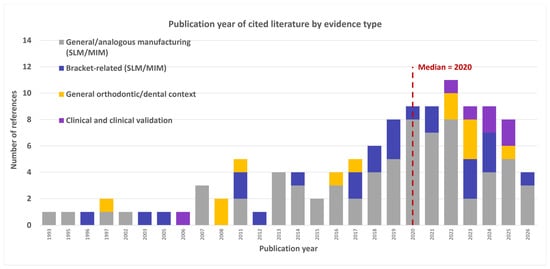
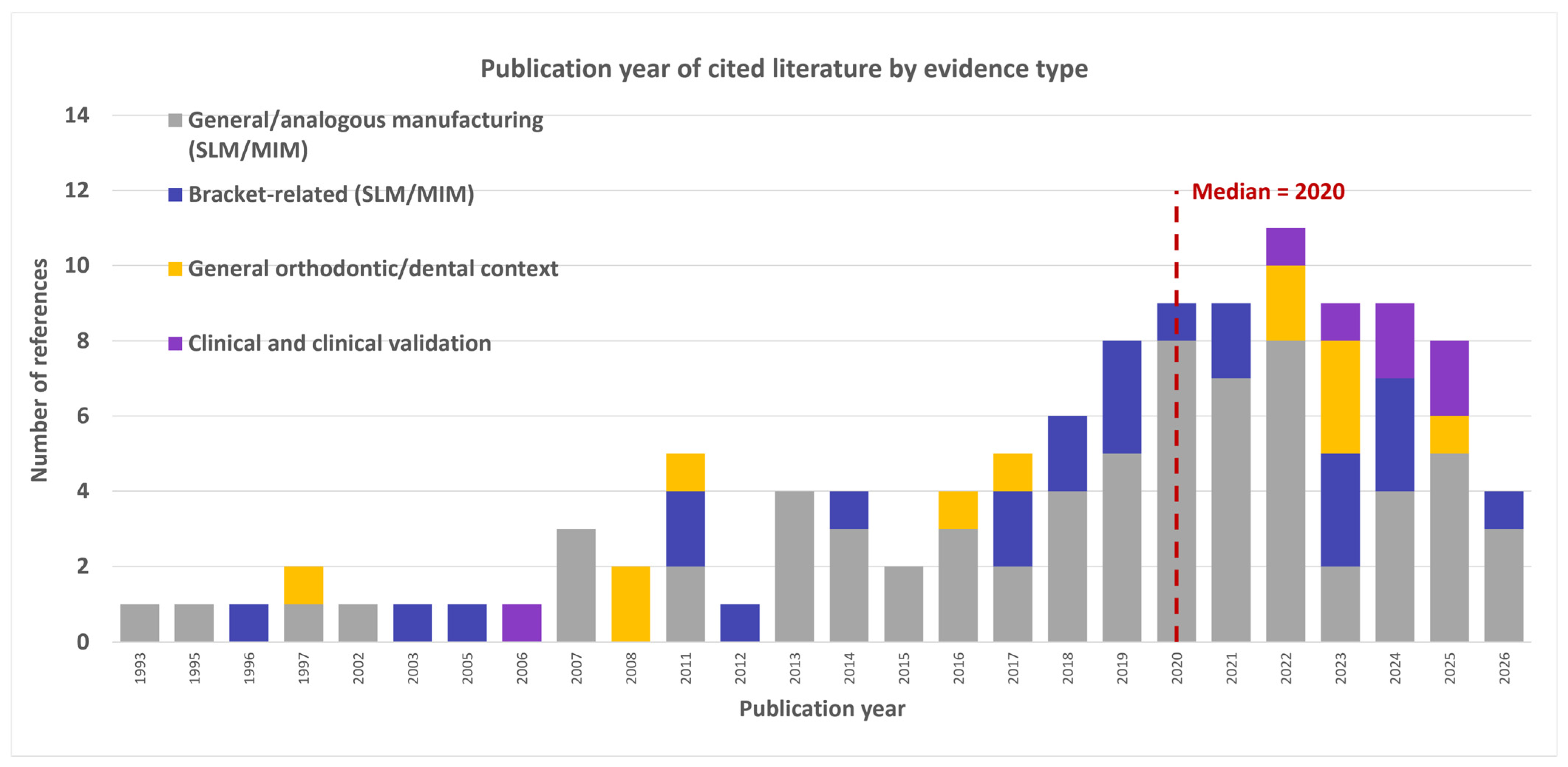
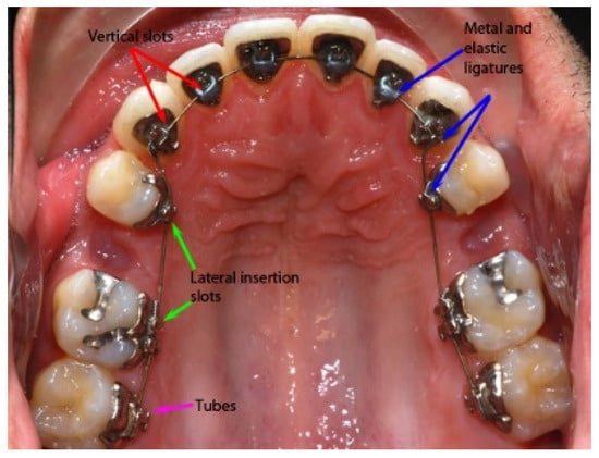
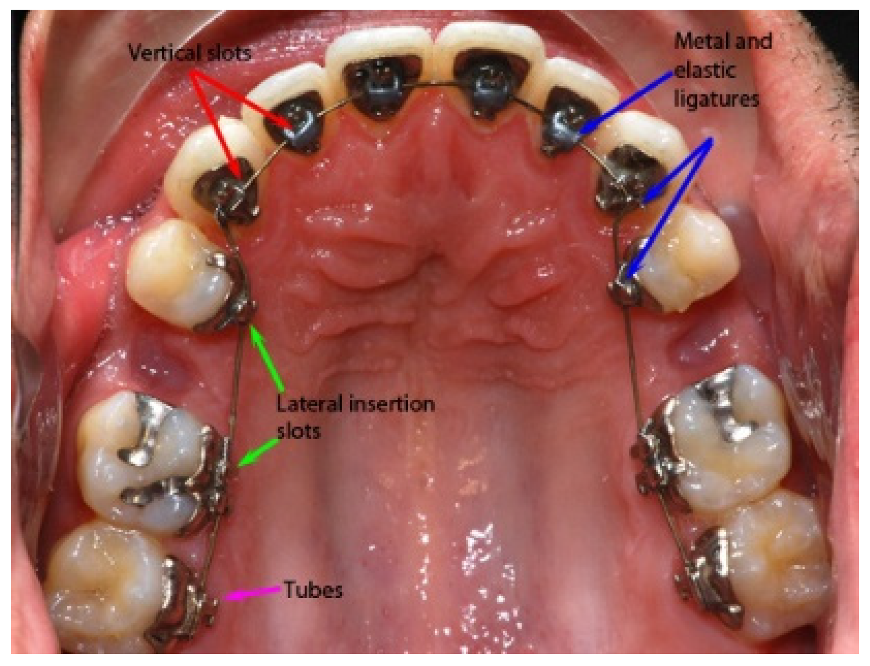
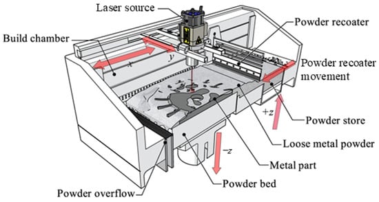
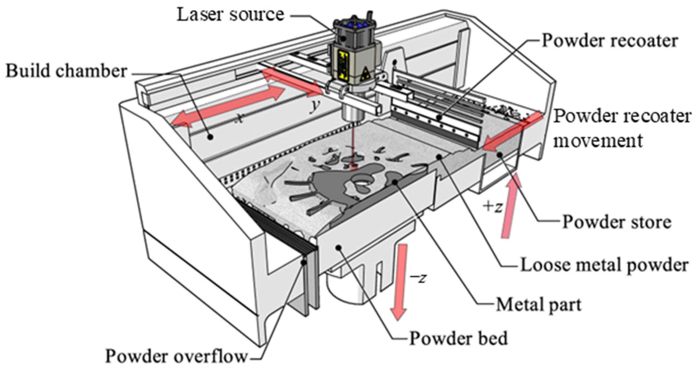
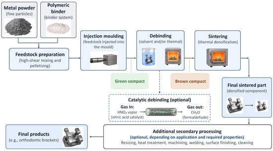
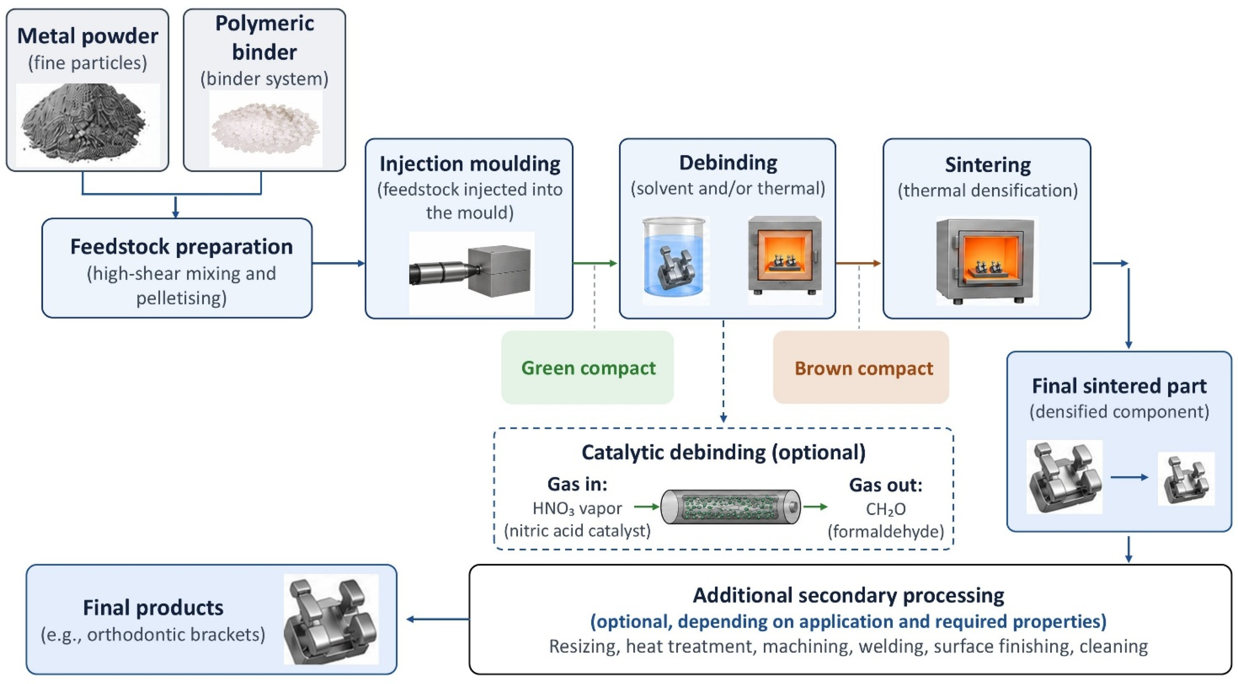
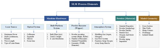
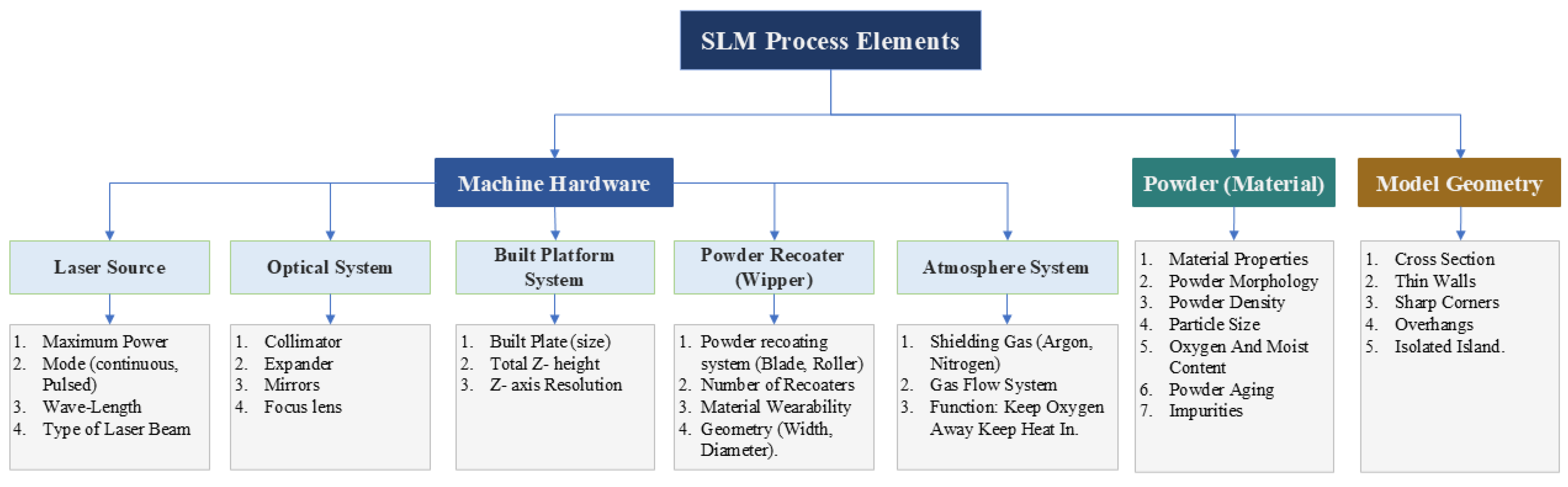
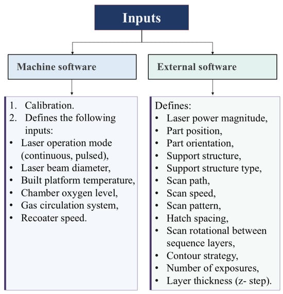
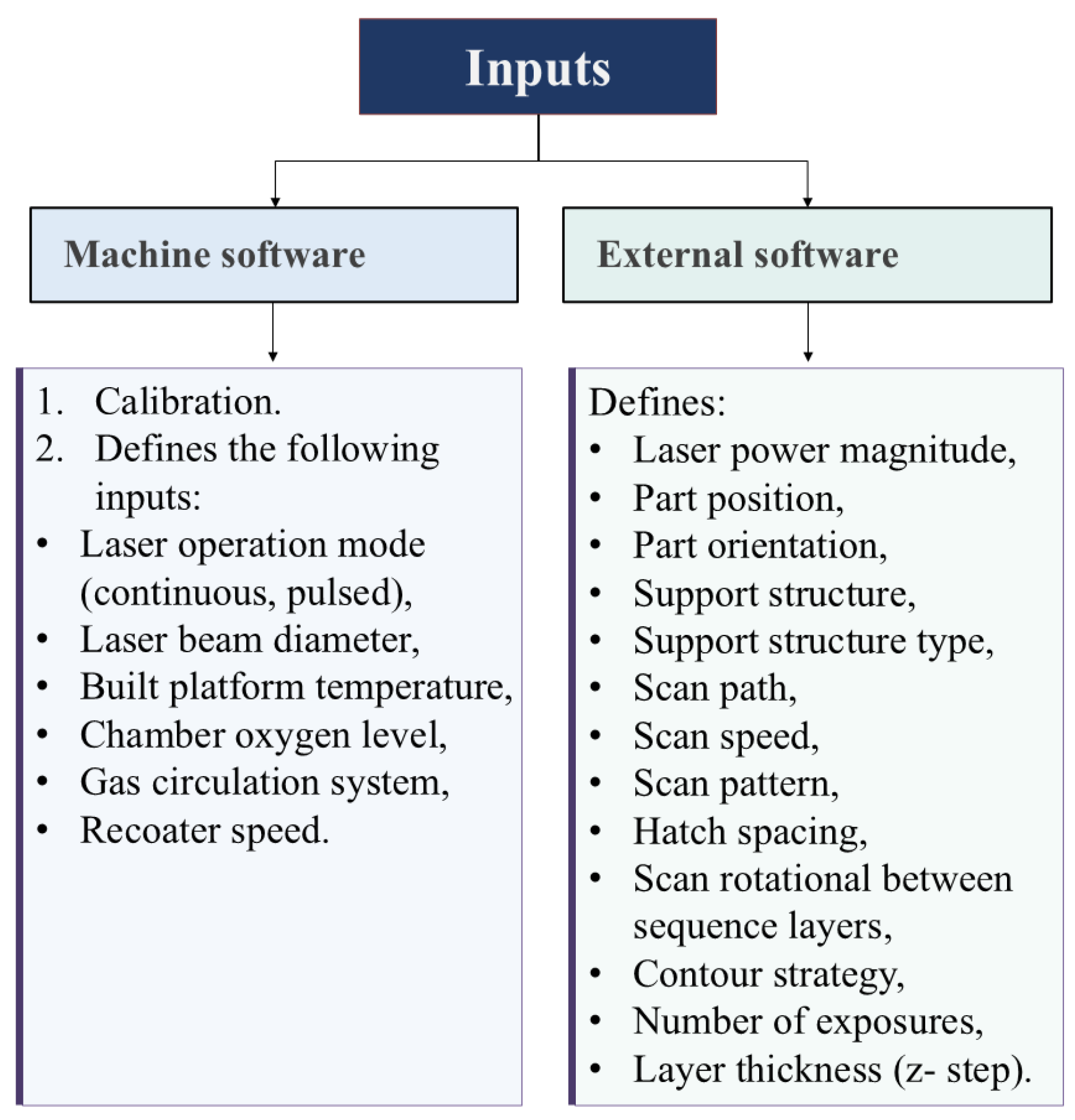
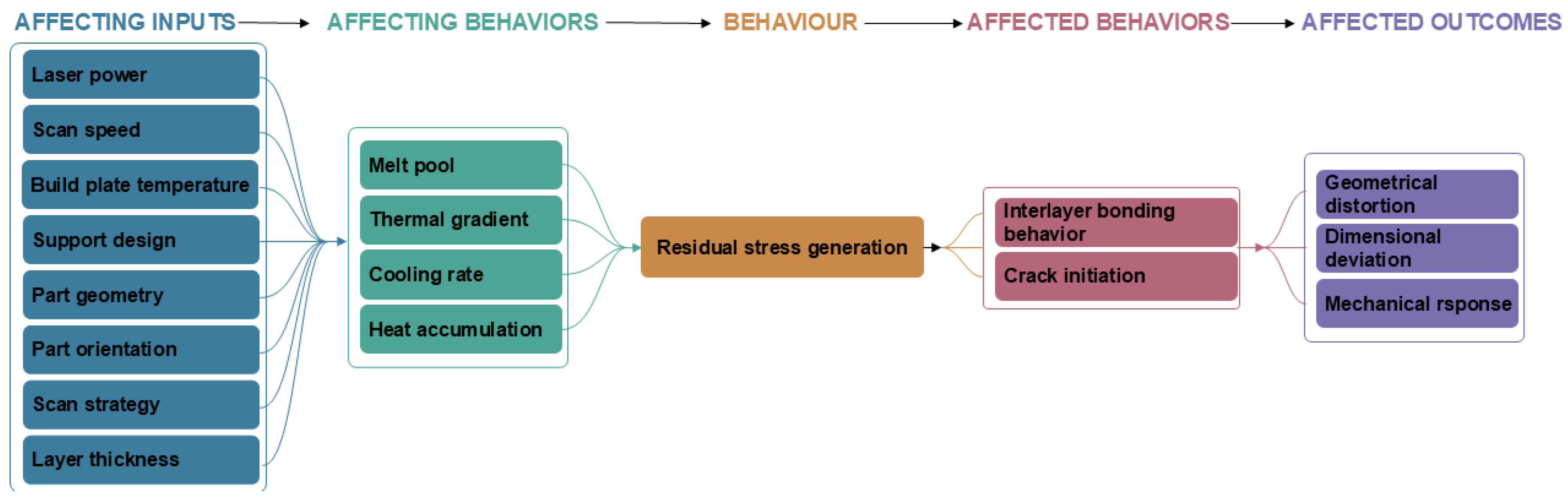
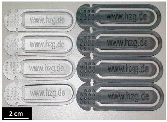
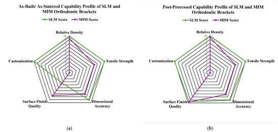
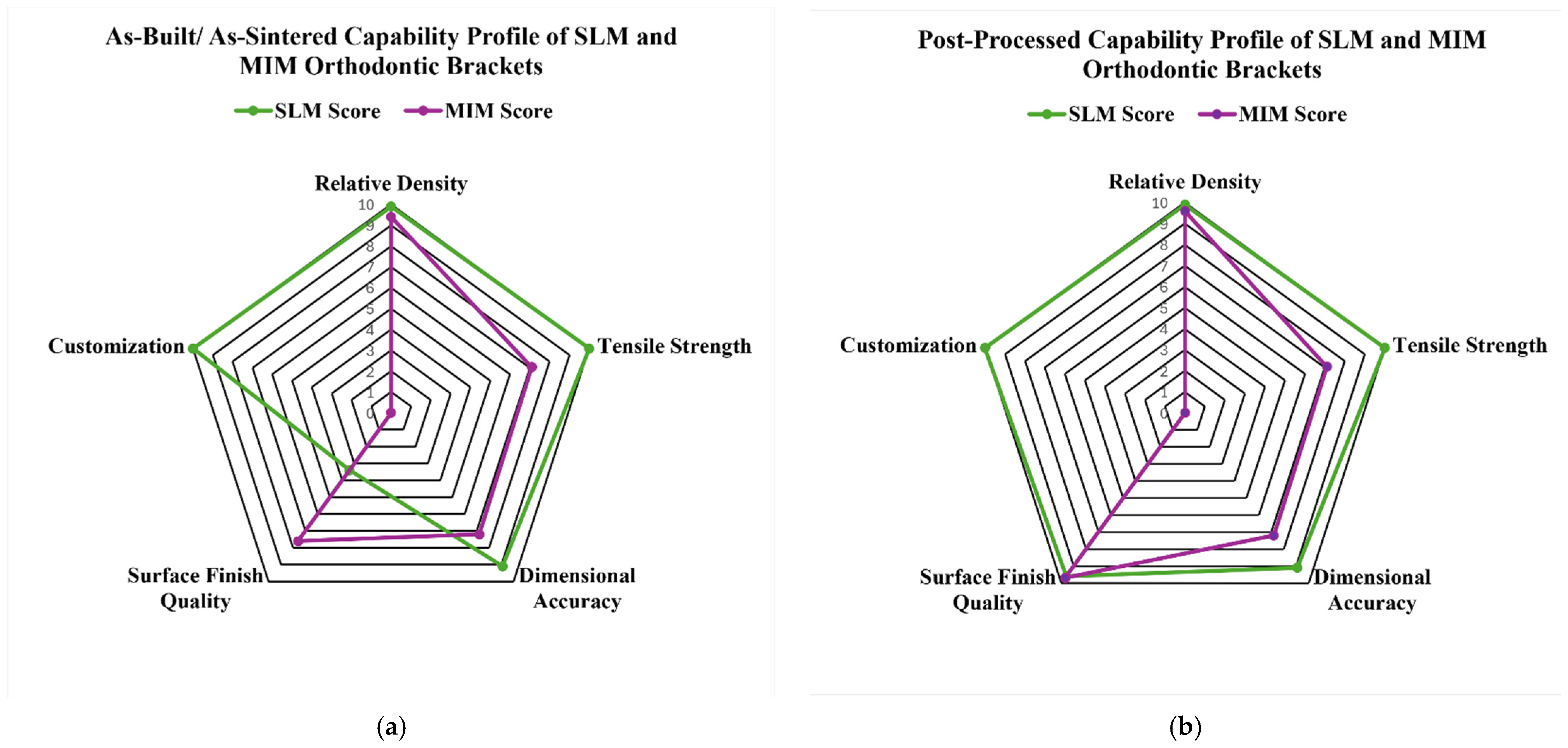

Disclaimer/Publisher’s Note: The statements, opinions and data contained in all publications are solely those of the individual author(s) and contributor(s) and not of MDPI and/or the editor(s). MDPI and/or the editor(s) disclaim responsibility for any injury to people or property resulting from any ideas, methods, instructions or products referred to in the content. |
© 2026 by the authors. Licensee MDPI, Basel, Switzerland. This article is an open access article distributed under the terms and conditions of the Creative Commons Attribution (CC BY) license.