Strategic Engineering Framework for Water Quality Resilience: Synergizing Passive Tidal Flushing with Active Ecological Interventions in Urban Canals

 , , , , and
Abstract
1. Introduction
2. Materials and Methods
2.1. Study Area
2.2. Monitoring Network and Data Acquisition
2.2.1. Monitoring Network: Internal, Discharge, and Downstream Stations
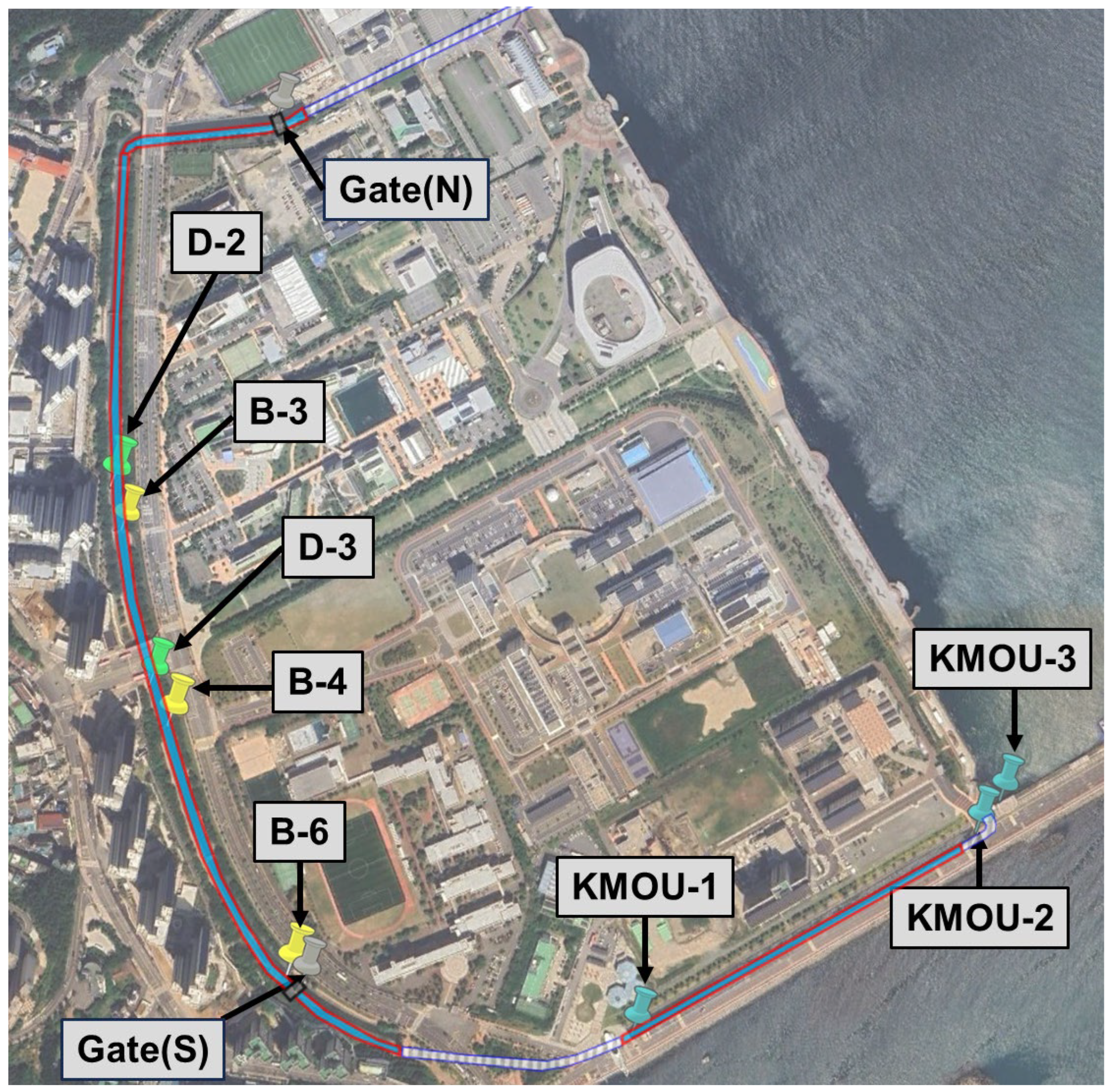
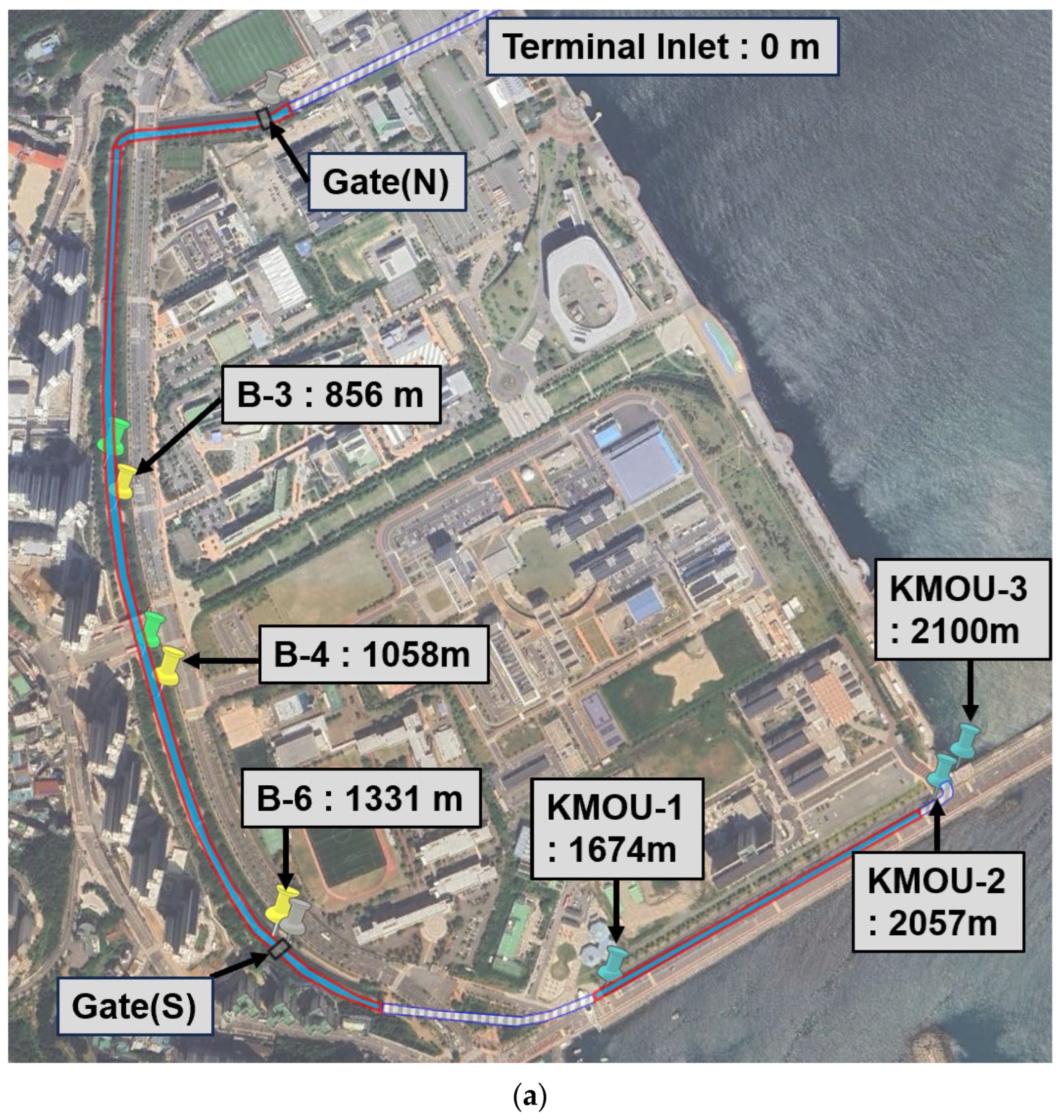
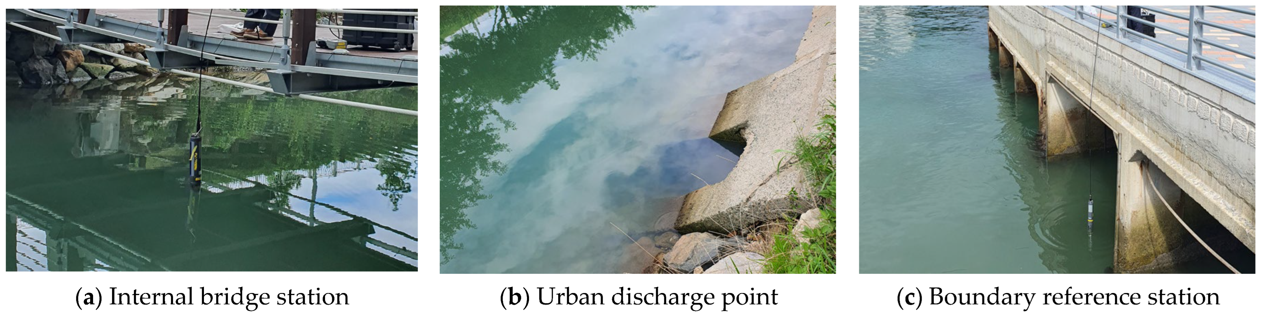
- Bridge-based Monitoring Stations (B-series): These stations are situated at strategic locations throughout the 1.6 km open channel section, selected based on the necessity for representative water quality assessment and ease of monitoring accessibility. Each station in the B-series is positioned at a bridge crossing, allowing for reliable access to the center-line of the canal’s width. This configuration ensures that the collected data accurately reflect the integrated water quality status while facilitating consistent long-term monitoring. These stations serve as the primary baseline for evaluating the canal’s general environmental conditions prior to the implementation of the proposed hybrid system.
- Urban Discharge Points (D-series): The urban discharge points (D-series) are defined as urban sewage outfalls where artificial effluent enters the tidal stream intermittently, often driven by irregular urban drainage or rainfall events. In a preliminary campaign, five potential D-series points were initially reviewed. Among these, D-2 and D-3 were specifically selected for D-series points, as the influx of sewage and other effluents was visually confirmed at these two locations. These locations are anticipated to exhibit high concentrations of COD, TN, and TP, reflecting the significant organic and nutrient loading typical of such episodic urban runoff. Consequently, these points are considered optimal candidates for the installation of vertical bio-curtains, which are designed to intercept nutrient and organic plumes at the source. The deployment of these components at the D-series points is intended to block the influx of pollutants before they disperse into the internal canal body, thereby mitigating hypoxia risks during stagnant tidal phases (Tidal window gaps).
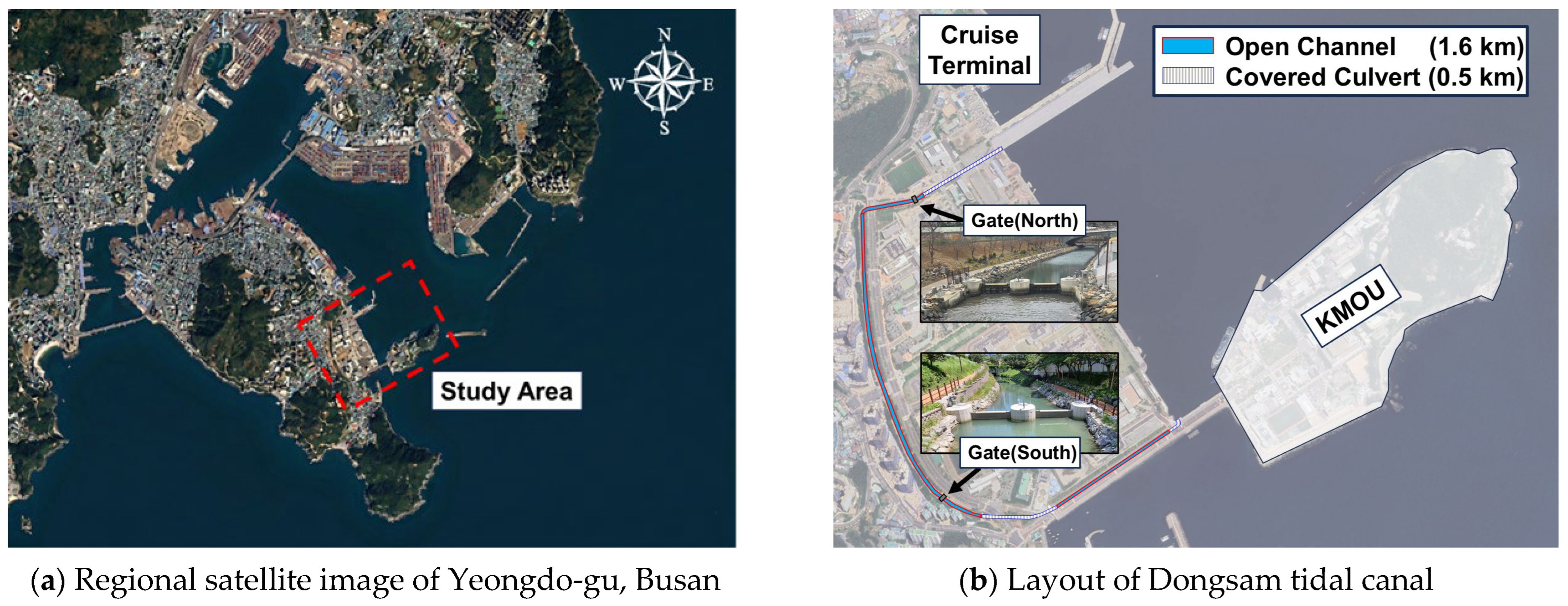
- Downstream Terminal Stations (KMOU-series): Positioned near the southern tidal gate near Korea maritime & ocean university, the KMOU-series stations serve as critical boundary reference points representing both ambient seawater conditions and downstream impacts. By monitoring the quality of the effluent as it discharges toward the open sea and comparing it with incoming tidal water, these stations provide a boundary reference to assess the net environmental impact of the canal on the broader coastal ecosystem. This allows for a clear distinction between internally generated pollutant loads and the background water quality of the Busan coastal area.
2.2.2. Instrumentation and Analytical Protocol
2.3. Passive Hydraulic Exchange Mechanism and Tidal Window Gap
3. Field Observation: Investigation of Mass Mortality and Tidal Flushing Efficacy
3.1. Investigation of the 2022 Mass Mortality Event and Hypoxia Onset
3.2. Spatial DO Profile and Chemical Pollutant Characterization
3.3. Efficacy of Sustained Tidal Exchange and Justification for Active Intervention
4. Proposed Hybrid Framework for Water Quality Improvement
4.1. Aeration System Design
4.1.1. Rationale and Theoretical Background
4.1.2. Optimization of Effective Width, Longitudinal Spacing, and Injection Angles
- Layout and O&M Optimization based on Effective Mixing Width ():
- −
- Single-sided Configuration (): For narrow channels where the total width does not exceed the reach of a single circulation cell, a single-sided wall installation is prioritized. This setup induces a single, large-scale circulation roll that covers the entire transverse section. By avoiding opposing flows, it maximizes energy efficiency and provides a continuous ‘oxygen refuge’ for mobile aquatic organisms during acute hypoxic events [23,24].
- −
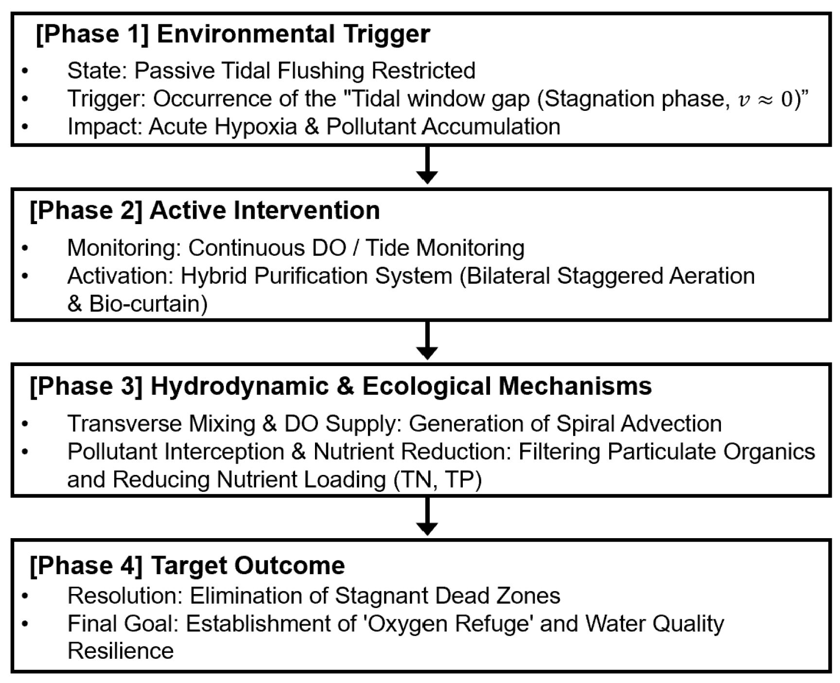
- Bilateral Staggered Configuration (): For wider urban canals where exceeds the reach of a single cell, installations on both walls are considered to expand the transverse coverage [22]. However, as established in aeration engineering, placing diffusers symmetrically on opposing walls can cause transverse flows to collide in the center and ascend rapidly, severely limiting air–water contact time [20]. By offsetting the units longitudinally on both walls, this staggered configuration prevents direct flow collision and generates a continuous, zig-zag spiral advection pattern. This effectively eliminates central ‘dead zones’ and promotes intensive transverse mixing across the entire width, extending the hydraulic retention time (HRT) [25].
- Practical Benefits for Operations and Maintenance (O&M):
- Optimization of Longitudinal Spacing () for Targeted Spiral Flow Stability:
- Geometrical Constraints and Lateral Coverage in Wide Canals:
- Vertical Clearance from the Bed ():
- Longitudinal Setback Distance () from Tidal Gates for Structural Safety:
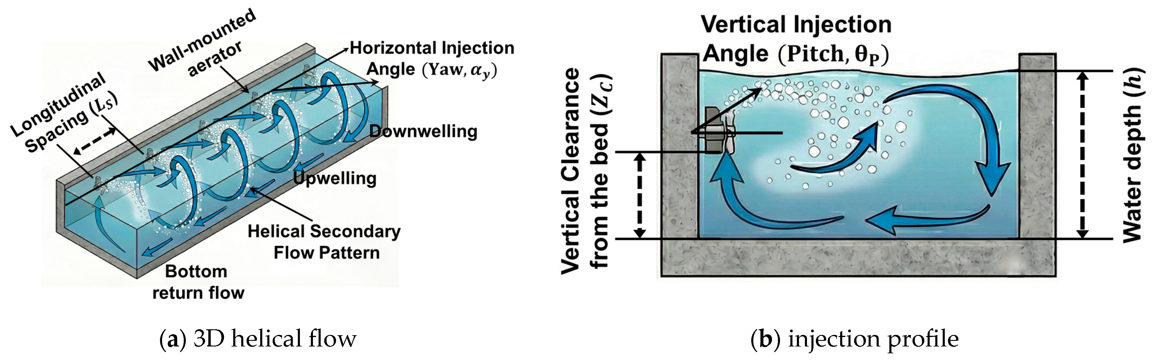
- Optimization of Diffuser Injection Angles (Pitch and Yaw) The orientation of the diffusers governs the efficiency and stability of the spiral flow. Based on hydrodynamic evaluations of spiral aeration systems and transverse mixing in shallow flows, the injection angles must be carefully calibrated in two planes to maximize the oxygen transfer mechanism:
- −
- Horizontal angle (Yaw, ): Instead of injecting air strictly perpendicular to the canal wall, the nozzles are oriented with a downstream bias of 30–45° relative to the transverse axis. In stagnant conditions where no background longitudinal velocity exists, this bias is essential to artificially generate longitudinal momentum. This transformation of the simple transverse roll into a helical (corkscrew) flow path ensures that oxygen-rich water is effectively transported toward remote longitudinal “dead zones” near the barrages, expanding the reach of the oxygen refuge [28].
- −
- Vertical angle (Pitch, ): The diffusers are oriented with an upward trajectory of 15–25° from the horizontal plane. This upward pitch is strategically designed to prevent the aeration jet from directly impacting the canal bed. By guiding the bubble plume along a rising diagonal path, the system maximizes the residence time of bubbles in the water column and promotes a large-scale transverse circulation cell [21].
4.2. Vertical Bio-Curtain Design
4.2.1. Theoretical Framework and Bio-Curtains Concept
4.2.2. Ecological Selection Criteria
4.2.3. Optimization of Root Depth () and Density ()
- Optimized Root Depth (): The effective root depth () is a fundamental determinant of interception efficiency within the canal system. For the target canal, which is distinguished by an operational depth () of approximately 2.0 m during the stagnant ‘Tidal window gap’, was scaled using a dimensionless immersion ratio that relates the root depth to the total water depth.
- Planting Density () and Climate-Adaptive Scaling: The areal planting density () is a critical factor governing the volumetric reactive surface area available for the establishment of periphytic biofilms. A higher density configuration fundamentally enhances the surface area-to-volume (SA/V) ratio, thereby promoting the development of root-associated biofilms that play a key role in nutrient removal processes in floating treatment wetlands [35]. According to comprehensive reviews of floating treatment wetlands (FTWs) [33,47], operational densities typically vary widely depending on target species and environmental conditions. Rather than applying a universal fixed value, this framework recommends adaptively scaling the density within a continuous operational spectrum (spanning approximately 12 to 32 plants/m2) based on local climatic constraints:
- −
- Cold Zones (12–16 plants/m2): Operating near the lower end of this density spectrum is recommended. This more conservative spacing maintains essential hydrodynamic porosity and prevents severe root overcrowding and anaerobic rot during prolonged winter dormant phases, ensuring plant survival when metabolic rates and oxygen translocation are minimal.
- −
- Temperate Zones (16–24 plants/m2): A median optimization approach is proposed as an optimal baseline. This range ensures rapid canopy closure and maximizes nutrient assimilation during the growing season, while maintaining sufficient spacing to prevent localized root-zone hypoxia during seasonal transitions.
- −
- Tropical Zones (24–32 plants/m2): Densities approaching the upper operational limits can be sustainably employed. This ultra-high-density configuration is strategically engineered to augment the SA/V ratio, effectively leveraging accelerated biomass accumulation and heightened microbial metabolism to handle the intensive organic loading typical of perennial warm-water environments.
4.2.4. Structural Support and Material Considerations: Vertical Guide Rails
4.3. Engineering Parameterization and Sensitivity Justification
4.3.1. Parameter Selection, Applicability, and Uncertainty
4.3.2. Range of Applicability and Remaining Uncertainty
4.3.3. Simplified Sensitivity Discussion
4.3.4. Structural Configuration and Maintenance-Driven Resilience
5. Case Studies and Strategic Implementation
5.1. Strategic Application to the Dongsam Tidal Canal
5.1.1. Optimization of Placement: and Oxygen Refuge Strategy
5.1.2. Layout of the Spiral Aeration Units: Dual-Scale ‘Stepping-Stone’ Refuge
- Type I: Ecological Refuge Nodes (B-4, B-6, KMOU-1):
- Type II: Targeted Control Nodes (D-2, D-3, Gates):
5.1.3. Hydrodynamic Safety and Operational Resilience
- Vertical Clearance and Submergence: The diffusers are mounted at a fixed elevation of 0.4 m above the canal bed—corresponding to 20% of the operational baseline depth ( = 2.0 m)—to minimize the resuspension of fine benthic sediments [26]. Even at the absolute minimum water level (0.74 m on 20 February 2022), a 0.34 m water cover (the submergence depth from the water surface to the diffuser unit) is expected to be maintained, which is anticipated to support uninterrupted operation without atmospheric exposure or surface splashing. Consequently, the proposed diffuser elevation provides a hydrodynamically stable configuration capable of maintaining continuous aeration performance under the variable water-level conditions characteristic of micro-tidal canal systems.
- Longitudinal Setback Distance (): To protect the mechanical units from high-velocity flushing jets during gate operations, units positioned near the tidal gates maintain a proposed setback distance () of 22.5 m. This value is derived from the hydrodynamic safety criterion of 15 , based on the maximum head difference ( = 1.5 m) established in Section 2.1 [25].
- Winter Ice Suppression Synergy: Despite this structural setback, the gate-adjacent Type II single-unit systems are anticipated to function as auxiliary ice-suppression mechanisms. Since the 22.5 m offset is within the effective reach of the localized spiral mixing generated by the unit, the forced advection of warmer, brackish benthic water is expected to reach the gate infrastructure. This continuous thermal transport is intended to help disrupt the static boundary layer, aiming to protect the critical gate mechanisms from frazil ice formation and potentially mitigating the risk of mechanical failure caused by localized freezing [27].
- Aeration Injection Angles: Following the optimization criteria established in Section 4, the diffuser units for the Dongsam tidal canal were configured with a horizontal angle of 45° and a vertical angle of 20°. This specific alignment is adopted to maximize the effective spiral mixing width () and facilitate vertical oxygen transport throughout the water column, while ensuring that the jet trajectory remains sufficiently clear of the canal bed to prevent localized benthic scouring.
5.1.4. Geometric Optimization, Density Configuration, and Aesthetic Integration
- Optimized Immersion and Bottom Clearance: Based on the operational baseline depth (), an optimized immersion ratio of 0.6 (equivalent to a 1.2 m root depth) is applied to intercept 60% of the water column. This configuration is strategically designed to maximize nutrient interception while maintaining a 0.8 m bottom gap. This clearance is designed to serve as a functional bypass zone, aiming to minimize hydrodynamic drag forces on the bio-curtain and ensure the preservation of hydraulic conveyance within the canal during high-velocity tidal flushing events.
- Optimized Vegetation Density (): Within the temperate thermal window of the target site (−15 °C to 35 °C), Iris pseudacorus was selected as the primary species for its exceptional metabolic adaptability and salinity tolerance. Aligning with the temperate scaling matrix established in Section 4 (16–24 plants/m2), a median-high density of 20 plants/m2 is implemented for the Dongsam tidal canal. This configuration is aimed at achieving a surface area-to-volume (SA/V) ratio estimated to be 3 to 5 times higher than traditional, scattered floating mats [35]. By increasing the available attachment surface for nitrifying biofilms and the frequency of root-water contact, this strategy is expected to enhance the potential for biofilm-mediated nutrient assimilation and suspended solid interception without inducing localized root-zone hypoxia.
- Aesthetic Integration and Landscape Value: As the canal serves as a recreational promenade, the bio-curtains are proposed to provide visual masking for unsightly infrastructure, such as sewage outfall pipes near D-2 and D-3. This nature-based integration is intended to improve landscape aesthetics and public perception, potentially enhancing the overall recreational experience for waterfront visitors and promoting the social acceptance of urban ecological restoration projects.
5.1.5. Adaptive Anchoring and Operational Resilience of Bio-Curtains
- FRP Guide Rail System for Tidal Adaptation: To accommodate the canal’s continuous bi-directional tidal fluctuations, vertical guide rails manufactured from fiber-reinforced polymer (FRP) are installed. These rails allow the bio-curtain modules to autonomously track the operational water levels, which vary from 0.74 m to 2.1 m, ensuring that the optimized 1.2 m root depth is consistently maintained. Given the estuarine nature of the Dongsam tidal canal, FRP is specifically selected for its exceptional resistance to chloride-induced corrosion in high-salinity seawater. This choice enhances long-term structural integrity and minimizes maintenance requirements, effectively mitigating the rapid degradation typical of conventional metallic fixtures in marine environments.
- Hydrodynamic Reconfiguration: During low-tide peaks, the flexible roots deflect downstream to maintain hydraulic conveyance. Simultaneously, the increased relative density of the root matrix within the reduced water column acts as a physical ‘straining sweep.’ This mechanism effectively traps suspended particles through interception and localized sedimentation, thereby polishing the discharge water by reducing turbidity before it exits the canal.
5.1.6. Hybrid Synergy: Spatial Allocation and Aeration Integration
- Targeted Scaling and Placement: Instead of broad spatial coverage, the bio-curtain modules are strategically deployed in concentrated clusters immediately adjacent to the primary inflow points. This placement is designed to intercept the pollution plume at its source before significant dispersion occurs. By utilizing a high areal planting density of 16–24 plants/m2, the configuration aims to establish a robust and dense rhizosphere. This high-density setup serves as the primary zone for intensive biofilm-mediated remediation, maximizing the volumetric reactive surface area where pollutant concentrations are highest. This targeted approach ensures that the localized hydrodynamic activation provided by the aeration units is fully leveraged for enhanced nutrient removal kinetics.
- HRT Optimization via Spiral Mixing: A single Type II spiral aeration unit is strategically integrated immediately upstream of the bio-curtain cluster. As discussed in Section 5.1.2, the primary objective of this setup is to extend the hydraulic retention time (HRT) rather than providing bulk aeration. The upward bubble plume is intended to generate a localized, controlled spiral mixing zone that retards pure longitudinal advection. This hydrodynamic delay is anticipated to allow the polluted water to permeate the root-biofilm matrix multiple times before exiting the treatment zone, effectively increasing the contact time.
- Enhanced Treatment Potential: This engineered synergy is expected to maximize the contact frequency between dissolved pollutants and the bio-reactive surfaces on the plant roots. Compared to traditional linear flow interception systems, this hybrid configuration is anticipated to significantly enhance the system’s nutrient sequestration and overall pollutant removal efficiency, offering a robust, proposed solution for point-source pollution control.
5.2. Preliminary Assessment of International Tidal Canals
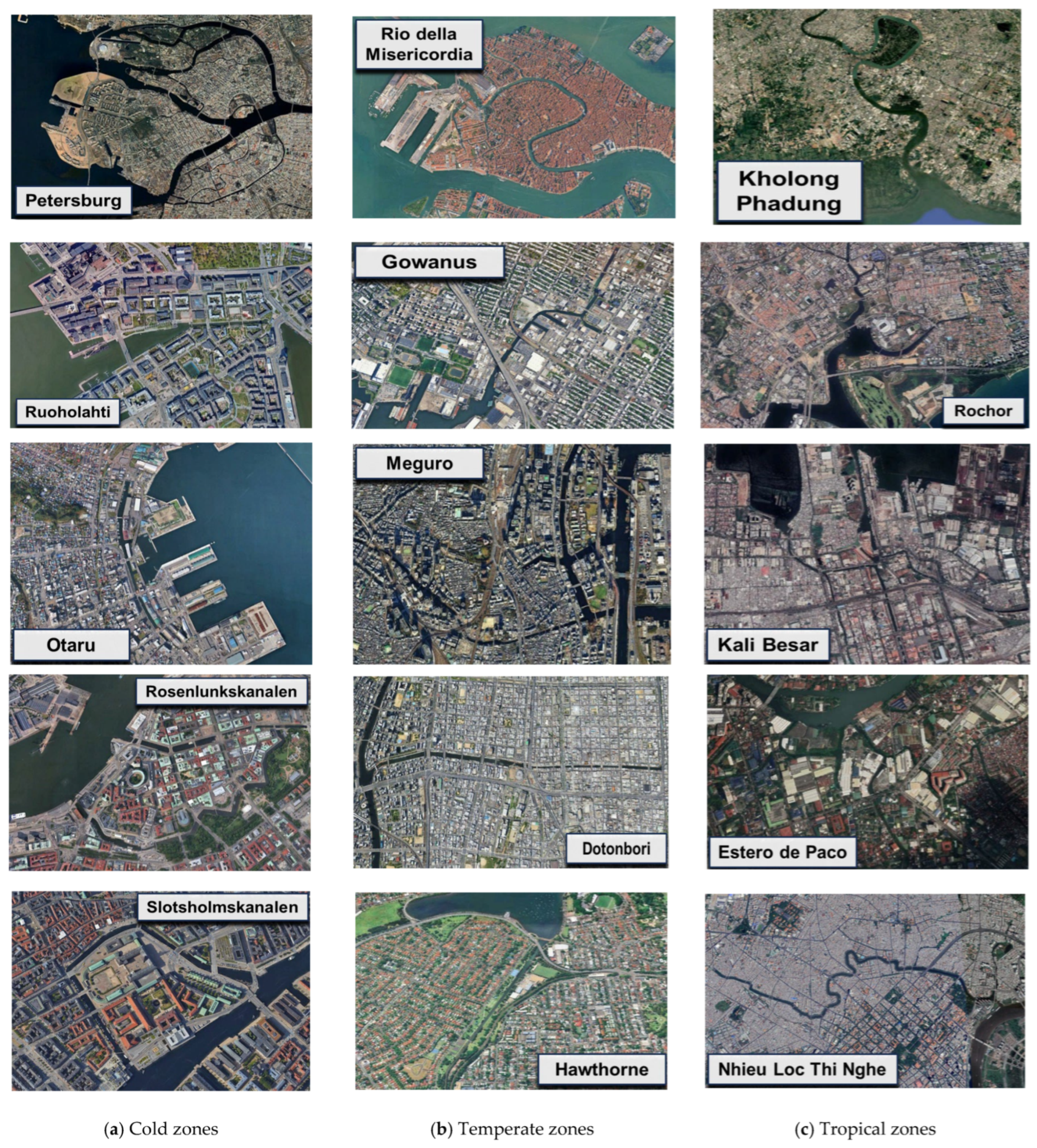
5.2.1. Selection of Target Micro-Tidal Canals and Environmental Profiles
5.2.2. Evaluation of Scaling Logic for Global Aeration Design
- Application of the Universal Scaling Parameter (): The core of the global design logic rests on the effective mixing width, defined as = 2.2. Across the 15 canals, where depths () range from 1.5 m (Estero de Paco) to 3.5 m (Gowanus canal), the calculated varies between 3.30 m and 7.70 m. Because the total width () of all 15 canals strictly exceeds the 2 (4.4) threshold, a bilateral staggered configuration is universally applied. This adaptive layout ensures that the spiral aeration units are not over-designed for narrow channels like the Rio della Misericordia ( = 12.5 m) while maintaining sufficient energy and transverse coverage to span the wider reaches of the Meguro River or Dotonbori Canal ( 27.5 m).
- Implementation of the Intensive Mixing Zone: For all selected sites, the target purification reach is proposed to be constrained within the intensive mixing zone. Based on the optimized safety margins in Section 5.1.1, this sequential reach—ranging from 45 m to 105 m to accommodate the varying depths ( = 1.5–3.5 m) of the 15 global canals—is intended to maximize the angular momentum of the spiral flow. By concentrating the bio-curtain clusters within this high-energy envelope, the system is anticipated to facilitate the most efficient contact between the polluted inflow and the nitrifying biofilms, regardless of the canal’s total longitudinal length.
- Strategic Node Allocation by Discharge Severity: The allocation between Type I (Refuge) and Type II (Targeted Control) nodes is proposed to scale with the “Urban discharge type” categorized in Table 4.
- −
- Severe Impact Zones (e.g., Kali Besar, Nhieu Loc-Thi Nghe): For canals receiving raw sewage or heavy CSOs, a sequential Type I relay system is proposed. By deploying units at intervals, the design aims to establish a continuous aerobic corridor to prevent localized fish kills during quiescent tidal intervals.
- −
- Moderate/Low Impact Zones (e.g., Griboyedov, Ruoholahti): In canals primarily affected by graywater or regulated runoff, localized Type II targeted control nodes are intended to provide an efficient, low-energy solution. These nodes focus on extending the hydraulic retention time (HRT) at specific point-source inflows, potentially enhancing nutrient sequestration without the need for full-corridor aeration.
- Performance Anticipation under ‘Worst-Case’ Stagnation: By optimizing the system for the ‘zero-flow’ conditions typical of the Dongsam tidal canal’s gate operations, the scaling logic is expected to remain robust across the 12 canals without formal gate systems. During natural slack tides or low-velocity periods common in these micro-tidal environments, the induced spiral momentum is anticipated to act as an artificial flushing mechanism, preventing the formation of stagnant boundary layers and maintaining the dissolved oxygen (DO) above the critical hypoxia threshold.
5.2.3. Evaluation of Scaling Logic for Global Bio-Curtain and Anchoring Design
- Biological Scaling and Density Gradient: To maximize nutrient sequestration potential, the planting density () is systematically scaled according to the thermal regimes and metabolic expectations defined in Section 4.2.2 and Section 4.2.3.
- −
- Cold Zones (12–16 plants/m2): A conservative density is applied to maintain essential hydrodynamic porosity, preventing root overcrowding and anaerobic rot during prolonged winter dormant phases. A polyculture strategy (Phragmites and Typha) is utilized to enhance winter resilience.
- −
- Temperate Zones (16–24 plants/m2): A median optimization approach is proposed as an optimal baseline. Utilizing monoculture (Iris pseudacorus), this range ensures rapid canopy closure and maximizes nutrient assimilation during the growing season while preventing localized root-zone hypoxia.
- −
- Tropical Zones (24–32 plants/m2): An ultra-high-density approach is employed to capitalize on year-round rapid biomass growth and elevated microbial kinetics. The polyculture of Canna and Cyperus maximizes the surface-area-to-volume (SA/V) ratio to effectively manage the massive organic loads typical of these environments.
- Adaptive Anchoring and Operational Resilience: The implementation of a robust vertical support system is the primary requirement for ensuring the physical stability and functional positioning of modular bio-curtains. For the 15 international canals, fiber-reinforced polymer (FRP) is proposed as the primary material for the vertical guide rails. FRP pultruded profiles exhibit superior chemical resilience against sulfides and organic acids common in untreated urban discharges—a strategic choice for cities like Bangkok, Manila, and Ho Chi Minh City, where microbial and chemical loads are substantial.
- Autonomous Water Level Tracking and Root Depth () Optimization: The FRP guide rail system allows the bio-curtain modules to autonomously track tidal fluctuations. This ensures that the root-biofilm matrix remains at the optimized immersion ratio ( = 0.6) regardless of the tidal phase. This autonomous adjustment maintains consistent interception of pollutant plumes from outfalls, preventing hydraulic bypass during high-tide events.
- Landscape and Social Value: Beyond structural durability, these anchored systems are strategically positioned to provide a visual masking effect. By concealing unsightly infrastructure, such as exposed sewage pipes or stormwater conduits in high-traffic promenades like Tokyo’s Meguro River or Osaka’s Dotonbori Canal, the nature-based integration enhances public perception and the recreational experience for waterfront visitors.
6. Conclusions
6.1. Summary
6.2. Limitations and Recommendations
Author Contributions
Funding
Data Availability Statement
Acknowledgments
Conflicts of Interest
Correction Statement
Abbreviations
| COD | Chemical Oxygen Demand |
| CSO | Combined Sewer Overflow |
| DO | Dissolved Oxygen |
| FTW | Floating Treatment Wetland |
| FRP | Fiber-Reinforced Polymer |
| HRT | Hydraulic Retention Time |
| KHOA | Korea Hydrographic and Oceanographic Agency |
| KMOU | Korea Maritime & Ocean University |
| NbS | Nature-based Solution |
| O&M | Operations and Maintenance |
| OTE | Oxygen Transfer Efficiency |
| SA/V | Surface Area-to-Volume |
| SOD | Sediment Oxygen Demand |
| TN | Total Nitrogen |
| TP | Total Phosphorus |
| ZAI | Zone of Aeration Influence |
References
- Monsen, N.E.; Cloern, J.E.; Lucas, L.V.; Monismith, S.G. A comment on the use of flushing time, residence time, and age as transport time scales. Limnol. Oceanogr. 2002, 47, 1545–1553. [Google Scholar] [CrossRef]
- Johnston, S.G.; Slavich, P.G.; Hirst, P. The impact of controlled seawater exchange on water quality in acid sulfate soil environments. Agric. Water Manag. 2005, 73, 87–112. [Google Scholar] [CrossRef]
- Jin, S.; Kim, D.; Lim, H.S.; Lee, H.J. Variability of flow velocity induced by Dongsam Seawater Stream Floodgate installation. J. Coast. Disaster Prev. 2021, 8, 267–274. (In Korean) [Google Scholar] [CrossRef]
- Hong, S.; Jin, S.; Kim, K.T.; Kim, D.; Kim, J.; Jang, S.C.; Kim, H.; Park, J.H.; Lim, H.S. The effects of increasing flow velocity and improving water quality in Dongsam seawater stream through bi-directional sluice gates operation and tidal range drainage. J. Coast. Disaster Prev. 2023, 10, 95–109. (In Korean) [Google Scholar] [CrossRef]
- Cooke, G.D.; Welch, E.B.; Peterson, S.A.; Nichols, S.A. Restoration and Management of Lakes and Reservoirs, 3rd ed.; CRC Press: Boca Raton, FL, USA, 2005. [Google Scholar] [CrossRef]
- Beutel, M.W.; Horne, A.J. A review of the effects of hypolimnetic oxygenation on lake and reservoir water quality. Lake Reserv. Manag. 1999, 15, 285–297. [Google Scholar] [CrossRef]
- Ashley, K.I. Artificial Circulation in British Columbia: Review and Evaluation; Fisheries Technical Circular No. 78; Ministry of Environment and Parks, Fisheries Branch: Victoria, BC, Canada, 1987. [Google Scholar]
- Chyan, J.M.; Lin, C.J.; Lin, Y.C.; Chou, Y.A. Improving removal performance of pollutants by artificial aeration and flow rectification in free water surface constructed wetland. Int. Biodeterior. Biodegrad. 2016, 113, 146–154. [Google Scholar] [CrossRef]
- ASCE/EWRI. Measurement of Oxygen Transfer in Clean Water; ASCE/EWRI 2-06; American Society of Civil Engineers: Reston, VA, USA, 2007. [Google Scholar]
- U.S. Environmental Protection Agency (EPA). Combined Sewer Overflow O&M Fact Sheet; EPA 832-F-99-039; Office of Water: Washington, DC, USA, 1999.
- Korea Hydrographic and Oceanographic Agency (KHOA). Tide Tables for Coast of Korea; KHOA: Busan, Republic of Korea, 2022.
- National Institute of Fisheries Science (NIFS). Standard Methods for Marine Environmental Examination; Notice No. 2021-7; NIFS: Busan, Republic of Korea, 2021. Available online: https://www.nifs.go.kr/board/actionBoard0052List.do (accessed on 4 April 2026). (In Korean)
- Chow, V.T. Open-Channel Hydraulics; McGraw-Hill: New York, NY, USA, 1959. [Google Scholar]
- Henderson, F.M. Open Channel Flow; Macmillan: New York, NY, USA, 1966. [Google Scholar]
- Diaz, R.J.; Rosenberg, R. Spreading dead zones and consequences for marine ecosystems. Science 2008, 321, 926–929. [Google Scholar] [CrossRef] [PubMed]
- Vaquer-Sunyer, R.; Duarte, C.M. Thresholds of hypoxia for marine biodiversity. Proc. Natl. Acad. Sci. USA 2008, 105, 15452–15457. [Google Scholar] [CrossRef]
- Ministry of Environment (MOE). Enforcement Decree of the Framework Act on Environmental Policy, [Annex 1] Environmental Standards for Lakes; Ministry of Environment: Sejong, Republic of Korea, 2025. (In Korean)
- Moon, H.C.; Kim, Y.Y.; Seo, I.S.; Kim, J.S.; Kim, G.H.; Hwang, S.M.; Song, J.H.; Kim, T.H. Water Quality Characteristics of Artificial Streams in Shihwa Industrial Complex. J. Korean Soc. Environ. Anal. 2018, 21, 1–10. (In Korean) [Google Scholar]
- Jung, Y.; Kim, S. Characteristics of Stormwater Runoff from Urban areas with Industrial Complex. J. Wetl. Res. 2012, 14, 131–137. (In Korean) [Google Scholar] [CrossRef]
- Tchobanoglous, G.; Stensel, H.D.; Tsuchihashi, R.; Burton, F.L. Wastewater Engineering: Treatment and Resource Recovery, 5th ed.; McGraw-Hill Education: New York, NY, USA, 2014. [Google Scholar]
- Fayolle, Y.; Cockx, A.; Gillot, S.; Roustan, M.; Héduit, A. Oxygen transfer prediction in aeration tanks using CFD. Chem. Eng. Sci. 2007, 62, 7163–7171. [Google Scholar] [CrossRef]
- Chanson, H. The Hydraulics of Open Channel Flow: An Introduction, 2nd ed.; Butterworth-Heinemann: Oxford, UK, 2004. [Google Scholar]
- Eby, L.A.; Crowder, L.B. Hypoxia-based habitat compression in the Neuse River Estuary: Context-dependent shifts in behavioral avoidance thresholds. Can. J. Fish. Aquat. Sci. 2002, 59, 952–965. [Google Scholar] [CrossRef]
- Alp, E.; Melching, C.S. Allocation of supplementary aeration stations in the Chicago waterway system for dissolved oxygen improvement. J. Environ. Manag. 2011, 92, 1577–1583. [Google Scholar] [CrossRef] [PubMed]
- Novak, P.; Moffat, A.I.B.; Nalluri, C.; Narayanan, R. Hydraulic Structures, 4th ed.; Spon Press: London, UK, 2001. [Google Scholar]
- Unger, J.; Hager, W.H. Down-flow and horseshoe vortex characteristics of sediment embedded bridge piers. Exp. Fluids 2007, 42, 1–19. [Google Scholar] [CrossRef]
- Ashton, G.D. River and Lake Ice Engineering; Water Resources Publications: Littleton, CO, USA, 1986. [Google Scholar]
- Fischer, H.B.; List, E.J.; Koh, R.C.Y.; Imberger, J.; Brooks, N.H. Mixing in Inland and Coastal Waters; Academic Press: New York, NY, USA, 1979. [Google Scholar]
- Borne, K.E.; Fassman-Beck, E.A.; Winston, R.J.; Hunt, W.F.; Tanner, C.C. Implementation and Maintenance of Floating Treatment Wetlands for Urban Stormwater Management. J. Environ. Eng. 2015, 141, 04015017. [Google Scholar] [CrossRef]
- Vymazal, J. Removal of nutrients in various types of constructed wetlands. Sci. Total Environ. 2007, 380, 48–65. [Google Scholar] [CrossRef] [PubMed]
- Kadlec, R.H.; Wallace, S. Treatment Wetlands, 2nd ed.; CRC Press: Boca Raton, FL, USA, 2008. [Google Scholar]
- Li, X.N.; Song, H.L.; Li, W.; Lu, X.W.; Nishimura, O. An integrated ecological floating-bed employing plant, freshwater clam and biofilm carrier for purification of eutrophic water. Ecol. Eng. 2010, 36, 382–390. [Google Scholar] [CrossRef]
- Colares, G.S.; Dell’Osbel, N.; Wiesel, P.G.; Oliveira, G.A.; Lemos, P.H.Z.; da Silva, F.P.; Lutterbeck, C.A.; Kist, L.T.; Machado, Ê.L. Floating treatment wetlands: A review and bibliometric analysis. Sci. Total Environ. 2020, 714, 136776. [Google Scholar] [CrossRef]
- Borne, K.E. Floating treatment wetlands: Influences on the fate and removal performance of phosphorus in stormwater retention ponds. Ecol. Eng. 2014, 69, 76–82. [Google Scholar] [CrossRef]
- Headley, T.R.; Tanner, C.C. Constructed wetlands with floating emergent macrophytes: An innovative stormwater treatment technology. Crit. Rev. Environ. Sci. Technol. 2012, 42, 2261–2310. [Google Scholar] [CrossRef]
- Haslam, S.M. Biological flora of the British Isles: Phragmites communis Trin. J. Ecol. 1972, 60, 585–610. [Google Scholar] [CrossRef]
- Grace, J.B.; Harrison, J.S. The biology of Canadian weeds. 73. Typha latifolia L., Typha angustifolia L. and Typha xglauca Godr. Can. J. Plant Sci. 1986, 66, 361–379. [Google Scholar] [CrossRef]
- Vymazal, J. Plants used in constructed wetlands with horizontal subsurface flow: A review. Hydrobiologia 2011, 674, 133–156. [Google Scholar] [CrossRef]
- Kaseva, M.E. Performance of a sub-surface flow constructed wetland in polishing pre-treated wastewater—A tropical case study. Water Res. 2004, 38, 681–687. [Google Scholar] [CrossRef]
- Sutherland, W.J. Biological flora of the British Isles: Iris pseudacorus L. J. Ecol. 1990, 78, 833–848. [Google Scholar] [CrossRef]
- Wu, S.; Kuschk, P.; Brix, H.; Vymazal, J.; Dong, R. Development of constructed wetlands in performance intensifications for wastewater treatment: A nitrogen and organic matter targeted review. Water Res. 2014, 57, 40–55. [Google Scholar] [CrossRef]
- Konnerup, D.; Koottatep, T.; Brix, H. Treatment of domestic wastewater in tropical, subsurface flow constructed wetlands planted with Canna and Heliconia. Ecol. Eng. 2009, 35, 248–257. [Google Scholar] [CrossRef]
- Muthuri, F.M.; Jones, M.B.; Imbamba, S.K. Papyrus: Primary productivity of papyrus (Cyperus papyrus) in a tropical swamp; Lake Naivasha, Kenya. Biomass 1989, 18, 1–14. [Google Scholar] [CrossRef]
- Kyambadde, J.; Kansiime, F.; Gumaelius, L.; Dalhammar, G. A comparative study of Cyperus papyrus and Miscanthidium violaceum-based constructed wetlands for wastewater treatment in a tropical climate. Water Res. 2004, 38, 475–485. [Google Scholar] [CrossRef]
- Tanner, C.C.; Headley, T.R. Components of floating emergent macrophyte treatment wetlands influencing removal of stormwater pollutants. Ecol. Eng. 2011, 37, 474–486. [Google Scholar] [CrossRef]
- Winston, R.J.; Hunt, W.F.; Kennedy, S.G.; Merriman, L.S.; Chandler, J.; Brown, D. Evaluation of floating treatment wetlands as retrofits to existing stormwater retention ponds. Ecol. Eng. 2013, 54, 254–265. [Google Scholar] [CrossRef]
- Pavlineri, N.; Skoulikidis, P.T.; Tsihrintzis, V.A. Constructed floating wetlands: A review of research, design, operation and management aspects, and data meta-analysis. Chem. Eng. J. 2017, 308, 1120–1132. [Google Scholar] [CrossRef]
- Francis, R.A.; Hoggart, S.P.G. Waste not, want not: The need to utilize existing artificial structures for habitat improvement along urban rivers. Restor. Ecol. 2008, 16, 372–382. [Google Scholar] [CrossRef]
- Hollaway, L.C. A review of the present and future utilisation of FRP composites in the civil infrastructure. Constr. Build. Mater. 2010, 24, 2428–2445. [Google Scholar] [CrossRef]
- Karbhari, V.M.; Chin, J.W.; Hunston, D.; Benmokrane, B.; Juska, T.; Morgan, R.; Lesko, J.J.; Sorathia, U.; Reynaud, D. Durability gap analysis for fiber-reinforced polymer composites in civil infrastructure. J. Compos. Constr. 2003, 7, 238–247. [Google Scholar] [CrossRef]
- Sen, R.; Mullins, G. Application of FRP composites for underwater piles repair. Compos. Part B Eng. 2007, 38, 751–758. [Google Scholar] [CrossRef]
- Breitburg, D. Effects of hypoxia, and the balance between hypoxia and enrichment, on coastal fishes and fisheries. Estuaries 2002, 25, 767–781. [Google Scholar] [CrossRef]
- Google Earth Pro, Version 7.3.6; Google LLC: Mountain View, CA, USA, 2026. Available online: https://www.google.com/earth/ (accessed on 21 February 2026).



| Date | Station | Layer | Depth (m) | Temp (°C) | Salinity (psu) | DO (mg/L) |
|---|---|---|---|---|---|---|
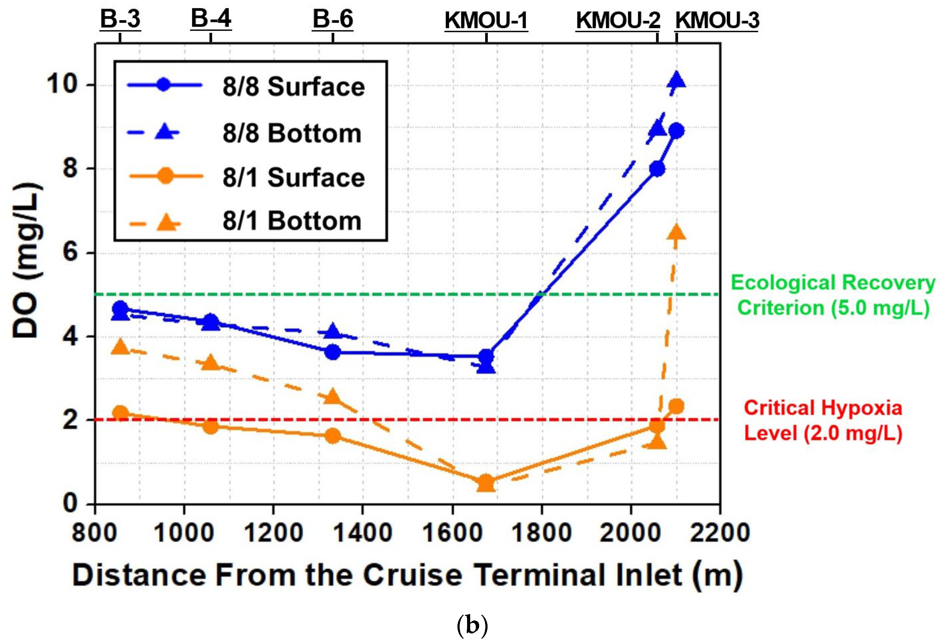
| 1 August 2022. (Event) | B-3 | Surface | 0.0 | 25.08 | 26.08 | 2.18 |
| B-3 | Bottom | 1.23 | 23.33 | 31.28 | 3.72 | |
| B-4 | Surface | 0.0 | 24.63 | 29.09 | 1.87 | |
| B-4 | Bottom | 1.01 | 23.36 | 31.13 | 3.35 | |
| B-6 | Surface | 0.0 | 23.95 | 28.77 | 1.64 | |
| B-6 | Bottom | 1.24 | 23.42 | 30.52 | 2.53 | |
| KMOU-1 | Surface | 0.0 | 23.51 | 29.21 | 0.55 | |
| KMOU-1 | Bottom | 1.02 | 22.91 | 30.65 | 0.44 | |
| KMOU-2 | Surface | 0.0 | 23.90 | 30.73 | 1.89 | |
| KMOU-2 | Bottom | 0.42 | 23.89 | 30.73 | 1.47 | |
| KMOU-3 | Surface | 0.0 | 23.77 | 30.90 | 2.35 | |
| KMOU-3 | Bottom | 1.63 | 22.46 | 31.93 | 6.46 | |
| 8 August 2022. (Recovered) | B-3 | Surface | 0.0 | 23.40 | 29.48 | 4.67 |
| B-3 | Bottom | 0.47 | 21.17 | 31.56 | 4.53 | |
| B-4 | Surface | 0.0 | 23.57 | 29.28 | 4.37 | |
| B-4 | Bottom | 0.37 | 22.65 | 30.58 | 4.30 | |
| B-6 | Surface | 0.0 | 23.19 | 30.31 | 3.64 | |
| B-6 | Bottom | 0.72 | 22.98 | 30.62 | 4.09 | |
| KMOU-1 | Surface | 0.0 | 23.36 | 29.80 | 3.53 | |
| KMOU-1 | Bottom | 0.90 | 22.62 | 31.00 | 3.28 | |
| KMOU-2 | Surface | 0.0 | 21.13 | 32.42 | 8.01 | |
| KMOU-2 | Bottom | 1.10 | 19.98 | 32.85 | 8.95 | |
| KMOU-3 | Surface | 0.0 | 20.21 | 32.76 | 8.92 | |
| KMOU-3 | Bottom | 1.42 | 19.00 | 33.06 | 10.10 |
| Analysis Points | COD (mg/L) | TN (mg/L) | TP (mg/L) |
| D-2 | 9.18 | 6.62 | 0.78 |
| D-3 | 10.11 | 12.50 | 2.89 |
| Climate Zone | Representative Species | Survival Range (°C) | Optimal Range (°C) | Removal Efficiency of TN (%) | Removal Efficiency of TP (%) |
|---|---|---|---|---|---|
| Cold | Phragmites australis Typha latifolia | −20 to 45 [36] −15 to 40 [37] | 15–30 [38] 15–30 [37] | 40–70 [30] 45–75 [39] | 30–50 [30] 45–75 [39] |
| Temperate | Iris pseudacorus | −15 to 35 [40] | 15–30 [40] | 50–80 [41] | 40–70 [41] |
| Tropical | Canna indica Cyperus papyrus | −5 to 40 [31] 10 to 40 [31] | 25–35 [42] 20–35 [43] | 60–85 [42] 55–80 [44] | 50–80 [42] 45–75 [44] |
| Climate Zone | Location (City, Country) | Annual Temp. (°C) | Length (km) | Rep. Width (m) | Depth (m) | Max. Tidal Range (m) | Urban Discharge Type (Sewage & CSOs) |
|---|---|---|---|---|---|---|---|
| Cold | Griboyedov Canal (St. Petersburg, Russia) | −15 to 25 | 5.0 | 22.5 (20–25) | 2.25 (2.0–2.5) | <0.5 | Moderate (Sewer Leaks) |
| Ruoholahti Canal (Helsinki, Finland) | −10 to 23 | 1.2 | 17.5 (15–20) | 2.50 (2.0–3.0) | <0.5 | Low-Moderate (Stormwater) | |
| Otaru Canal (Otaru, Japan) | −8 to 26 | 1.1 | 25.0 (20–30) | 2.00 (1.5–2.5) | <0.5 | Low-Moderate (Graywater) | |
| Rosenlundskanalen (Gothenburg, Sweden) | −5 to 24 | 1.5 | 20.0 (15–25) | 2.25 (2.0–2.5) | 0.5 | Moderate (CSOs) | |
| Slotsholmskanalen (Copenhagen, Denmark) | −3 to 25 | 1.0 | 22.5 (20–25) | 2.75 (2.5–3.0) | <0.5 | Low (Regulated Runoff) | |
| Temperate | Rio della Misericordia (Venice, Italy) | −2 to 33 | 1.2 | 12.5 (10–15) | 2.00 (1.5–2.5) | 1.0 | High (Domestic Sewage) |
| Gowanus Canal (New York, NY, USA) | −5 to 34 | 2.9 | 30.0 | 3.50 (3.0–4.0) | 1.4 | Severe (CSOs) | |
| Meguro River (Tokyo, Japan) | 0–35 | 4.0 | 27.5 (25–30) | 2.50 (2.0–3.0) | 1.5 | Moderate-High (CSOs) | |
| Dotonbori Canal (Osaka, Japan) | 2–35 | 2.7 | 27.5 (25–30) | 2.50 (2.0–3.0) | <1.5 * | High (Commercial Runoff) | |
| Hawthorne Canal (Sydney, Australia) | 8–30 | 2.5 | 17.5 (15–20) | 1.75 (1.5–2.0) | 1.5 | Moderate (Stormwater) | |
| Tropical | Khlong Phadung (Bangkok, Thailand) | 22–38 | 5.5 | 22.5 (20–25) | 2.50 (2.0–3.0) | ~1.5 * | Severe (Untreated Runoff/ Graywater) |
| Rochor Canal (Singapore) | 24–34 | 1.5 | 22.5 (20–25) | 2.25 (2.0–2.5) | <0.5 * | Moderate (Monsoon Runoff) | |
| Kali Besar (Jakarta, Indonesia) | 24–35 | 1.2 | 25.0 (20–30) | 2.00 (1.5–2.5) | 1.0 | Severe (Raw Sewage) | |
| Estero de Paco (Manila, Philippines) | 23–35 | 2.9 | 12.5 (10–15) | 1.50 (1.0–2.0) | 1.0 | Severe (Domestic Discharge) | |
| Nhieu Loc-Thi Nghe (Ho Chi Minh, Vietnam) | 22–36 | 8.7 | 27.5 (25–30) | 2.50 (2.0–3.0) | 1.8 | High (CSOs) |
| Climate Zone | Location (City, Country) | Layout Configuration | (m) | (m) | (m) | (m) |
|---|---|---|---|---|---|---|
| Cold | Griboyedov Canal (St. Petersburg, Russia) | Bilateral Staggered | 5.0 | 67 | 0.45 | 7.5 |
| Ruoholahti Canal (Helsinki, Finland) | Bilateral Staggered | 5.5 | 75 | 0.50 | 7.5 | |
| Otaru Canal (Otaru, Japan) | Bilateral Staggered | 4.4 | 60 | 0.40 | 7.5 | |
| Rosenlundskanalen (Gothenburg, Sweden) | Bilateral Staggered | 5.0 | 67 | 0.45 | 7.5 | |
| Slotsholmskanalen (Copenhagen, Denmark) | Bilateral Staggered | 6.1 | 82 | 0.55 | 7.5 | |
| Temperate | Rio della Misericordia (Venice, Italy) | Bilateral Staggered | 4.4 | 60 | 0.40 | 15.0 |
| Gowanus Canal (New York, NY, USA) | Bilateral Staggered | 7.7 | 105 | 0.70 | 21.0 | |
| Meguro River (Tokyo, Japan) | Bilateral Staggered | 5.5 | 75 | 0.50 | 22.5 | |
| Dotonbori Canal (Osaka, Japan) | Bilateral Staggered | 5.5 | 75 | 0.50 | 22.5 | |
| Hawthorne Canal (Sydney, Australia) | Bilateral Staggered | 3.9 | 52 | 0.35 | 22.5 | |
| Tropical | Khlong Phadung (Bangkok, Thailand) | Bilateral Staggered | 5.5 | 75 | 0.50 | 22.5 |
| Rochor Canal (Singapore) | Bilateral Staggered | 5.0 | 67 | 0.45 | 7.5 | |
| Kali Besar (Jakarta, Indonesia) | Bilateral Staggered | 4.4 | 60 | 0.40 | 15.0 | |
| Estero de Paco (Manila, Philippines) | Bilateral Staggered | 3.3 | 45 | 0.30 | 15.0 | |
| Nhieu Loc-Thi Nghe (Ho Chi Minh, Vietnam) | Bilateral Staggered | 5.5 | 75 | 0.50 | 27.0 |
| Climate Zone | Location (City, Country) | Representative Species | Root depth (m) | ) (plants/m2) | Adaptive Anchoring (Guide Rail) |
|---|---|---|---|---|---|
| Cold | Griboyedov Canal (St. Petersburg, Russia) | Phragmites australis & Typha latifolia | 1.35 | 12–16 | FRP (Ice & Salt resilience) |
| Ruoholahti Canal (Helsinki, Finland) | 1.50 | Corrosion-resistant poly-coated | |||
| Otaru Canal (Otaru, Japan) | 1.20 | FRP (Winter salt tolerance) | |||
| Rosenlundskanalen (Gothenburg, Sweden) | 1.35 | Reinforced FRP (CSO durability) | |||
| Slotsholmskanalen (Copenhagen, Denmark) | 1.65 | Standard durable synthetic | |||
| Temperate | Rio della Misericordia (Venice, Italy) | Iris pseudacorus | 1.20 | 16–24 | FRP (High salinity & sewage) |
| Gowanus Canal (New York, NY, USA) | 2.10 | FRP (Severe CSO resilience) | |||
| Meguro River (Tokyo, Japan) | 1.50 | FRP (Aesthetic & durable) | |||
| Dotonbori Canal (Osaka, Japan) | 1.50 | FRP (Commercial runoff protection) | |||
| Hawthorne Canal (Sydney, Australia) | 1.05 | FRP (Estuarine marine grade) | |||
| Tropical | Khlong Phadung (Bangkok, Thailand) | Canna indica & Cyperus papyrus | 1.50 | 24–32 | FRP (High chemical resistance) |
| Rochor Canal (Singapore) | 1.35 | FRP (UV & monsoon stability) | |||
| Kali Besar (Jakarta, Indonesia) | 1.20 | FRP (Severe organic load) | |||
| Estero de Paco (Manila, Philippines) | 0.90 | FRP (Informal settlement discharge) | |||
| Nhieu Loc-Thi Nghe (Ho Chi Minh, Vietnam) | 1.50 | FRP (High microbial load) |
Disclaimer/Publisher’s Note: The statements, opinions and data contained in all publications are solely those of the individual author(s) and contributor(s) and not of MDPI and/or the editor(s). MDPI and/or the editor(s) disclaim responsibility for any injury to people or property resulting from any ideas, methods, instructions or products referred to in the content. |
© 2026 by the authors. Licensee MDPI, Basel, Switzerland. This article is an open access article distributed under the terms and conditions of the Creative Commons Attribution (CC BY) license.
Share and Cite
Hong, S.; Choi, J.Y.; Kim, K.T.; Kwon, S.; Kim, J.; Lim, H.S. Strategic Engineering Framework for Water Quality Resilience: Synergizing Passive Tidal Flushing with Active Ecological Interventions in Urban Canals. J. Mar. Sci. Eng. 2026, 14, 731. https://doi.org/10.3390/jmse14080731
Hong S, Choi JY, Kim KT, Kwon S, Kim J, Lim HS. Strategic Engineering Framework for Water Quality Resilience: Synergizing Passive Tidal Flushing with Active Ecological Interventions in Urban Canals. Journal of Marine Science and Engineering. 2026; 14(8):731. https://doi.org/10.3390/jmse14080731
Chicago/Turabian StyleHong, Sunghoon, Jin Young Choi, Kyung Tae Kim, Soonchul Kwon, Jeongho Kim, and Hak Soo Lim. 2026. "Strategic Engineering Framework for Water Quality Resilience: Synergizing Passive Tidal Flushing with Active Ecological Interventions in Urban Canals" Journal of Marine Science and Engineering 14, no. 8: 731. https://doi.org/10.3390/jmse14080731
APA StyleHong, S., Choi, J. Y., Kim, K. T., Kwon, S., Kim, J., & Lim, H. S. (2026). Strategic Engineering Framework for Water Quality Resilience: Synergizing Passive Tidal Flushing with Active Ecological Interventions in Urban Canals. Journal of Marine Science and Engineering, 14(8), 731. https://doi.org/10.3390/jmse14080731