


Abstract
The suction pile–gravity hybrid foundation (SPGH) has emerged as a novel foundation for floating wind turbines (FWTs) due to its superior bearing mechanism. In harsh marine environments, offshore wind turbine structures endure multidirectional wave–wind current loads, which are transmitted through mooring systems as complex multidirectional coupled loads (horizontal, vertical, bending moments, and torque), imposing severe challenges to the bearing capacity. Therefore, this study carries out 3D finite element simulations, utilizing the Hardening Soil–Small Strain constitutive model to simulate the stress–strain behavior of sand, to systematically investigate the failure modes and bearing capacity of SPGH foundations. The method underlying the failure envelope theory is proposed, applicable to tension-leg mooring systems (dominated by uplift and lateral loads) and catenary mooring systems (dominated by compression and lateral loads). Results indicate that under pure vertical uplift or torque loading, both SPGH and traditional SP foundations exhibit typical interfacial shear failure modes. Under pure horizontal or bending moment loading, SPGH and SP foundations exhibit rotational instability failure. The direction of vertical load has a significant impact on the bearing performance of SPGH foundations. In addition, horizontal load can increase its vertical uplift-bearing capacity by 46% and torque capacity by 48%. The enhancement effect of the bending moment load is more significant, and can increase the vertical uplift-bearing capacity by 115% and the torque-bearing capacity by 112%, respectively, while vertical downward loads within a certain range significantly improve horizontal and bending-bearing performance.
1. Introduction
With the development of offshore wind turbines towards deep-sea areas, floating wind turbines (FWTs) have become a more economical choice. The tension-leg mooring systems and catenary mooring systems have high requirements for the uplift-bearing capacity of the foundation. Gravity foundations and suction caisson foundations have become the main forms of foundation due to their excellent bearing capacity, simple installation, applicability to a wide water depth range, and economic advantages.
Currently, there is a clear understanding of the bearing characteristics of gravity foundations [1,2,3]. Studies have found that adding skirts to the bottom of gravity foundations can effectively enhance their bearing capacity. Many scholars have used physical experiments [4,5] and numerical simulations [6,7,8] to investigate the bearing characteristics of skirted gravity foundations and their failure envelopes under combined loads. However, due to the limitations of the structural form of gravity foundations, it is difficult to fully utilize the bottom soil of the foundation when providing bearing capacity.
For suction foundations, most scholars have employed physical model experiments [9,10,11,12] and numerical simulations [13,14,15,16] to investigate their ultimate bearing capacity characteristics under vertical, horizontal, and bending moment loads (V, H, M). Zhu et al. [17] analyzed the horizontal and vertical bearing capacities of suction pile foundations with an aspect ratio of 1 through physical model tests, proposing a bearing capacity calculation formula based on the experimental results. On this basis, Zhu et al. [9] investigated the influence of the aspect ratio of suction foundations on the overturning resistance capacity in silty sand, and proposed a prediction method for overturning resistance capacity based on measured data. Cheng et al. [18] employed an improved Mohr–Coulomb model considering critical state conditions, hardening–softening shear strength, internal friction, and the dilatancy angle of sand, and proposed a prediction method for the uplift capacity of suction pile foundation in sand. Kim et al. [19] systematically investigated the effect of anchor hole location on the ultimate uplift capacity of suction foundations in silty sand by developing a three-dimensional (3D) finite element model. Peng et al. [20] employed physical tests and a finite element model to thoroughly examine the interaction mechanisms and failure mechanisms between suction pile foundations and sand at different mooring depths under the inclined pulling loading. To better describe the bearing capacity of suction foundations under combined loading, most researchers have employed physical model tests [21,22,23], numerical simulations [8,24,25], and theoretical solutions [26,27] to investigate the bearing mechanism of suction foundations under combined loading (V, H, M). Extreme weather can subject foundations to out-of-plane loads. Li et al. [28] found that out-of-plane loads significantly increase shear stress in the surrounding soil, thereby reducing the ultimate bearing capacity of the foundation. Houlsby et al. [29] and Zhang et al. [30] investigated the effects of torque loads (T) on the bearing capacity of a suction foundation and pile foundation through in situ tests and centrifuge tests. Experimental results indicate that torque loads can cause the foundation to rotate, causing the surrounding soil to reach its ultimate shear strength, ultimately leading to shear failure and making the foundation more susceptible to damage.
Based on the literature survey, in deep-sea areas, gravity foundations and suction foundations, as potential foundations for FWTs, may suffer from insufficient bearing capacity. Based on the advantages of gravity foundations and suction pile foundations, the suction pile–gravity hybrid foundation (SPGH) has been proposed in recent years [31]. The SPGH foundation is formed by the combination of a gravity foundation and suction pile foundation, and demonstrates superior bearing performance compared to single foundation types. The SPGH foundation leverages both elements’ structural advantages to drive piles deep into the soil, mobilizing a wider range of passive soil pressure, as its effective depth far exceeds that of a gravity foundation. However, changes in the fundamental form are highly likely to alter its failure mechanism. For example, compared to a single gravity foundation, the SPGH foundation can mobilize deeper soil layers to provide bearing capacity. Compared to a single suction pile foundation, the SPGH foundation provides a bearing capacity through the greater self-weight and mobilization of a larger amount of soil. This also results in the bearing mechanism and failure mode of the new SPGH foundation differing from those of the classical gravity foundation and suction pile foundation.
Therefore, this paper aims to employ the finite element simulation software Plaxis 3D 2023.2 to establish a 3D finite element model to simulate the interaction between the SPGH foundation and marine soil. The Hardening Soil–Small Strain model is selected to simulate the stress–strain behavior of sand. This research systematically investigates the failure modes of SPGH and traditional suction pile (SP) foundations in sand under ultimate vertical (Vult), horizontal (Hult), bending moment (Mult), and torque (Tult) loads, and analyzes the differences in their bearing mechanisms to explore the composite bearing capacity of the SPGH under multiple coupled loads through the bearing capacity envelope. The main contributions of this study are as follows. By employing an advanced soil constitutive model, the bearing mechanism of the SPGH foundation under uniaxial loading was elucidated. Through systematic comparison with the bearing mechanism of a classical suction pile foundation, the essence of its bearing capability enhancement was clarified. Additionally, the failure envelope of the SPGH foundation under combined loading was investigated, and an empirical formula suitable for engineering stability assessment was developed.
2. Numerical Simulation Method
2.1. Finite Element Modeling
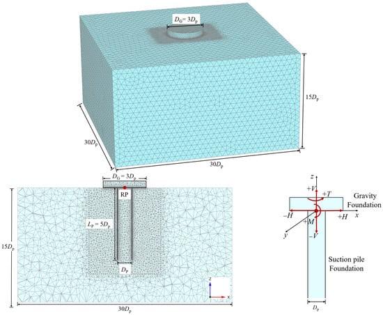
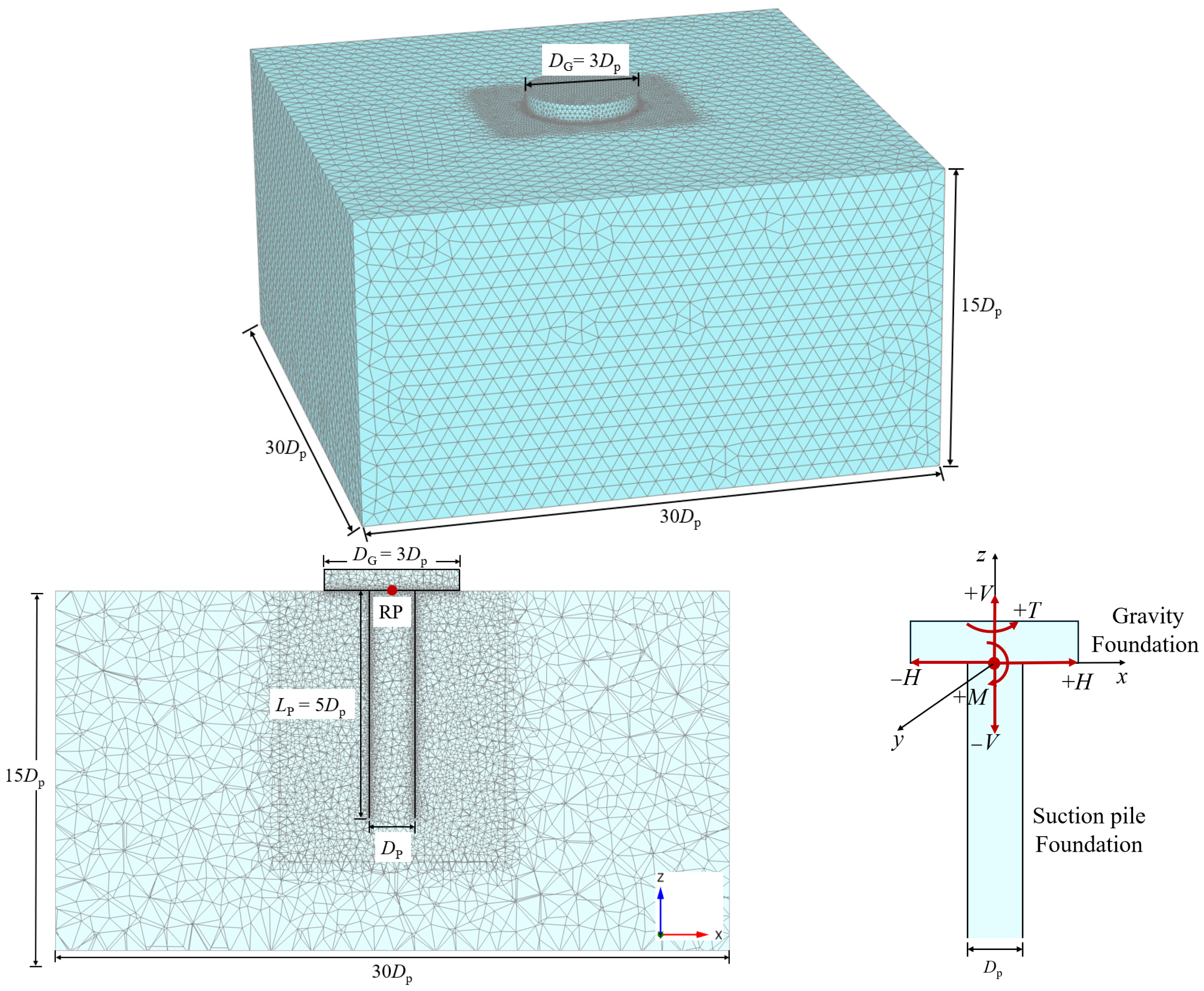
Figure 1 shows the 3D (three-dimensional) numerical model of the suction pile–gravity hybrid (SPGH) foundation, with marine soil developed employing the software Plaxis 3D. The SPGH foundation primarily consists of a combination of suction pile foundation and gravity foundation. The diameter of the suction pile foundation is set to 2 m (DP = 2 m), the pile length is 10 m (LP = 10 m) (aspect ratio of 5), and the diameter of the gravity foundation is set to 6 m (DG = 6 m, DG = 3 DP). It is worth noting that this article did not consider the influence of foundation self-weight when investigating the bearing behavior of SPGH. To simplify the model, the center point of the contact surface between the suction pile foundation and the gravity foundation is set as the reference point (RP), and loads, bending moments, and torques are all applied to the RP. The results indicate that setting the soil domain size to 60 m × 60 m × 30 m (length × width × height = 30 DP × 30 DP × 15 DP) can effectively avoid the influence of boundary effects on the calculation results. The base boundary of the model is considered as a rigid bedrock, while the top boundary is free, and the boundaries around the model only constrain horizontal displacement. The calculation of accuracy and efficiency can be guaranteed when the finite element model is discretized by 368,735 10-node tetrahedral elements. To improve computational efficiency, a smaller mesh is used near the foundation, and a larger mesh is used far away from the foundation.
Figure 1.
3D finite element model of the SPGH foundation.
Plaxis 3D simulates potential slippage or separation between the foundation and soil by adding a contact surface. The Hardening Soil–Small Strain (HSS) model is adopted to simulate the foundation–soil interface. In this model, the strength and stiffness parameters of the interface elements are derived from the surrounding soil layers, and the parameter Rinter (sand interface coefficient μ) is used to simulate the degree of reduction between the contact surfaces, where μ = 2/3tanφ, and φ is the internal friction angle of the sand. To better align with practical engineering, the contacts between the foundation and the soil are set to be capable of disengaging.
2.2. Constitutive Model
The Hardening Soil–Small Strain (HSS) model is an elastoplastic hyperbolic model, which can accurately simulate the variation in nonlinear elastic modulus with effective stress of sand, as well as the strength parameters and hardening characteristics during the plastic stage, but also considers the strain correlation of soil stiffness and can simulate different responses of soil in the range of small strain to large strain. The HSS model is based on the hyperbolic relationship between deviatoric stress (q) and axial strain (ε) observed in triaxial drained tests, and it incorporates both shear hardening and compression hardening, simulating irreversible strains induced by deviatoric loading and the irreversible compressive deformation of soil under primary compression conditions.
The HSS constitutive model has 10 basic parameters: pref, E50re, Eoedref, Eurref, φ′, ψ, cref, m, G0ref, and γ0.7, all of which are obtained from triaxial tests. Among them, pref is the reference confining pressure for triaxial tests; E50ref is the secant modulus at 50% of the ultimate load in the standard triaxial drained tests under the reference confining pressure pref, which mainly reflects the plastic strain caused by the principal deviatoric loading; Eoedref is the tangent stiffness modulus obtained from the consolidation tests, which is generally equal to the value of E50ref; Eurref is the unloading and reloading modulus under reference confining pressure pref, generally 3 times the value of E50ref; φ and ψ are the internal friction angle and dilation angle of sand, respectively; cref is the cohesive force of soil; m is a power exponent related to the stiffness stress level, which determines the stiffness modulus of E50 under different confining pressures; G0ref is the initial shear modulus under reference confining pressure pref; and γ0.7 is the shear strain level where the secant shear modulus is reduced to 70% of G0.
Ramirez et al. [32] conducted a series of drained monotonic triaxial compression tests on Ottawa sand with relative densities of 40% and 90%, which sufficiently covers most of the relative density range of the sand. The sand parameters are shown in Table 1. Axial pressures of 100, 200, and 300 kPa were applied to the sand elements. In nine drained monotonic triaxial compression tests, specimens were consolidated isotropically to three effective stress levels (100, 200, and 300 kPa).
Table 1.
Ottawa sand parameters in drained triaxial tests.
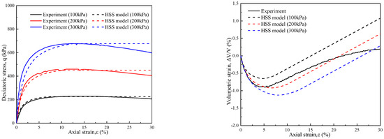
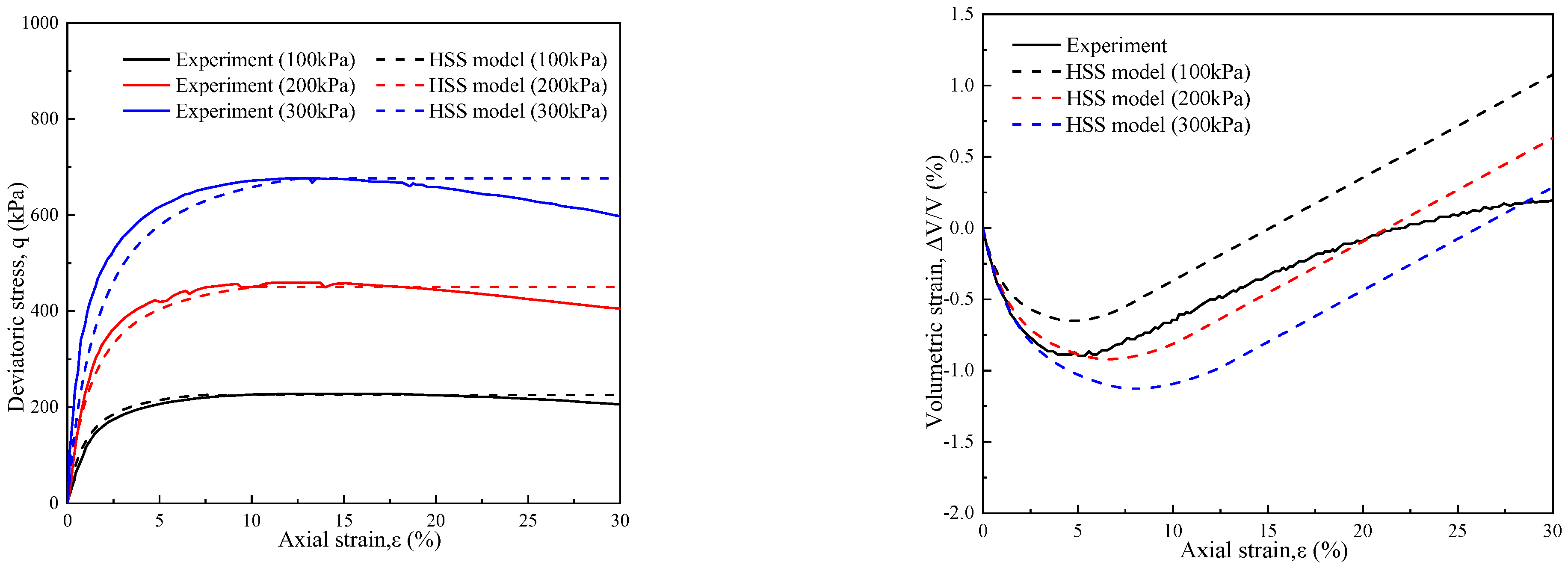
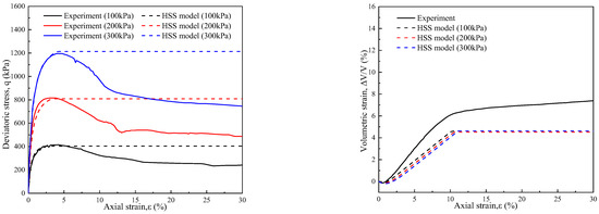
Figure 2 and Figure 3 show the measured and simulated results for Ottawa sand with relative densities of 40% and 90% in drained triaxial tests (axial pressures of 100, 200, and 300 kPa). As shown, the HSS constitutive model accurately simulates the peak deviatoric stress–axial strain relationship of Ottawa sand under different axial pressures. In addition, when Dr = 40%, the volumetric strain of Ottawa sand initially decreases and then increases with the growth of axial strain. When Dr = 90%, the volumetric strain of Ottawa sand gradually increases with the increase in axial strain. When the axial strain is greater than 10%, the volumetric strain of sand stops increasing because the void ratio of sand reaches the maximum value, and the volume of sand does not increase anymore. The HSS constitutive model effectively describes the volumetric strain–axial strain relationship of Ottawa sand under different Dr conditions. Table 2 summarizes all calibrated model parameters.
Figure 2.
Comparison of monotonic drained triaxial tests and numerical simulation (Dr = 40%).
Figure 3.
Comparison of monotonic drained triaxial tests and numerical simulation (Dr = 90%).
Table 2.
Parameters of Plaxis 3D.
2.3. Verification
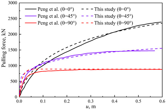
To validate the rationality of the HSS model and SPGH foundation finite element model, this study establishes a 3D finite element model based on the suction pile dimensions and soil parameters (in Table 3) reported in centrifugal tests by Peng et al. [20], to verify the displacement response of the suction pile foundation under different loading angles. The failure mode of the suction pile foundation is similar to that of the SPGH foundation. Therefore, validating the suction pile foundation to ensure the accuracy of the SPGH foundation is also sufficiently effective. The loading angle θ is the angle between the loading direction and the x-axis. The finite element simulation and experimental results are shown in Figure 4. During the initial loading phase, the pullout loads of the finite element simulation exceed the experimental results regardless of the loading angle. This discrepancy can be attributed to the finite element analysis neglecting the soil densification effect caused by the foundation installation [33]. When the displacement of the suction pile foundation reached 0.6 m (0.2 Dp), the foundation has been destroyed. The errors between the finite element results and article data (0°, 45°, and 90°) are 1.52%, 4.24%, and 1.04% under different loading angles, respectively. This close agreement further validates the accuracy of the finite element model.
Table 3.
The suction pile dimensions and soil parameters by Peng et al. [20].
Figure 4.
The finite element simulation and experimental results [20].
3. Results and Discussion
This section systematically investigates the failure mechanisms and bearing behavior of the SPGA foundation and traditional suction pile (SP) foundation (with dimensions as shown in the suction pile foundation in Figure 1) in sand with Dr = 40% under ultimate vertical (Vult), horizontal (Hult), bending moment (Mult), and torque (Tult) loading. Furthermore, the failure envelope curves method is employed to investigate its composite bearing capacity under various coupled load conditions. To clarify the loading directions for the foundation, loads applied along the positive direction of the coordinate axes are defined as positive loads (i.e., +H, +V). Bending moments applied along the y-axis in a clockwise direction are defined as positive bending moments (i.e., +M). Torque applied along the z-axis in a counterclockwise direction is defined as positive torque (i.e., +T). The simulation results are analyzed as follows.
3.1. Pure Uniaxial Capacities
3.1.1. Vertical Uplift Loading
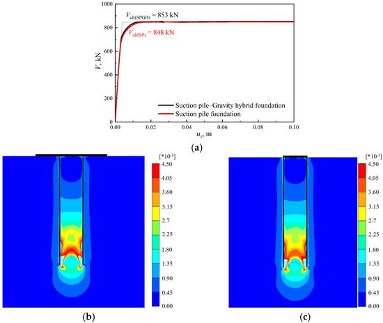
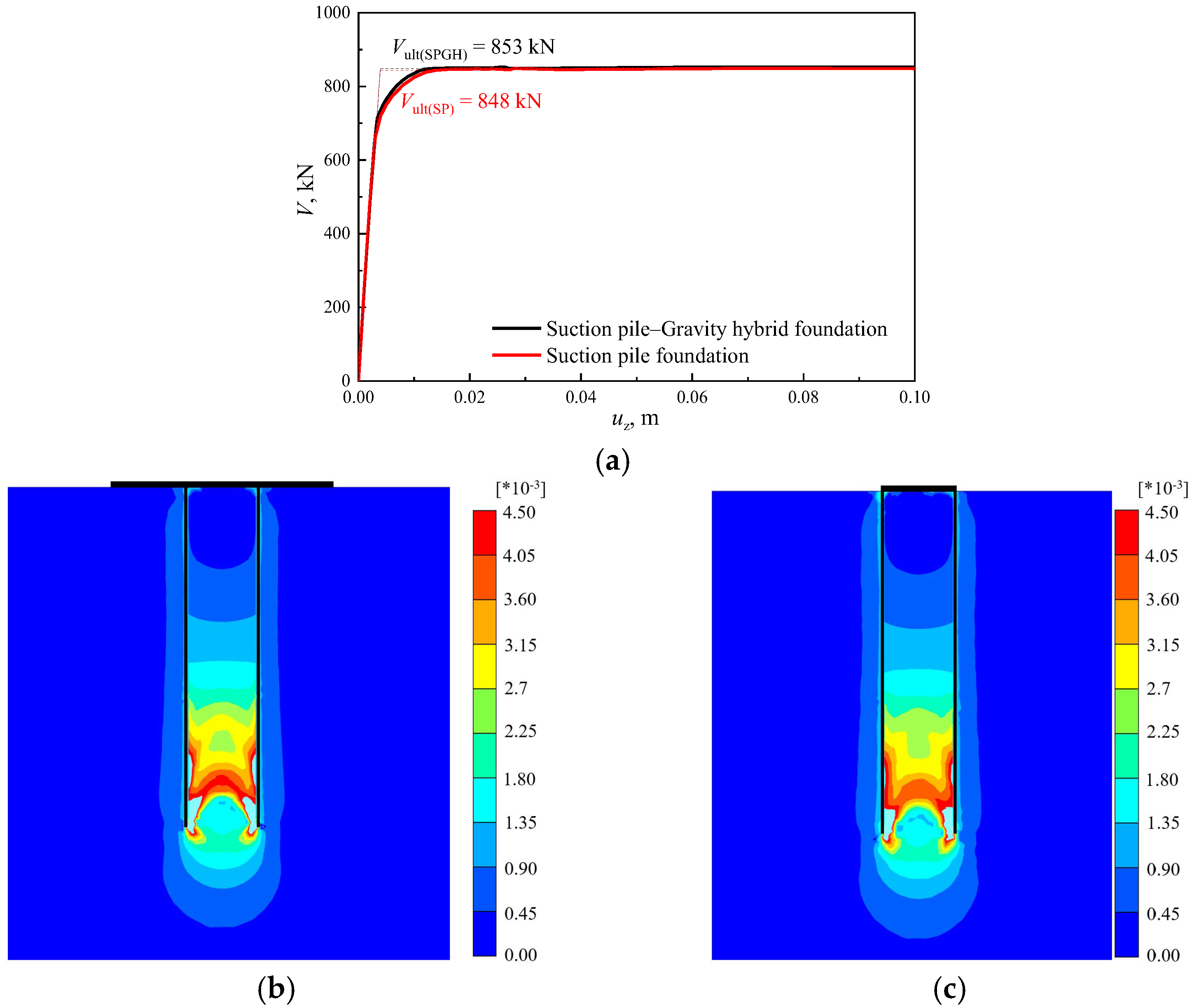
Figure 5 shows the bearing capacity curves and plastic strain of the SPGH foundation and SP foundation under vertical uplift loading in sand with Dr = 40%. As illustrated in Figure 5a, under vertical uplift loading, both the SPGH foundation and SP foundation exhibit slight vertical displacement and immediately reach the ultimate vertical bearing capacity, which is primarily related to the failure mechanism of foundations in the sand, as shown in Figure 5b,c. Under the ultimate vertical uplift load, the gravity foundation of the SPGH rapidly separates from the soil without providing interfacial resistance, so there is no significant plastic strain is observed in the soil beneath the gravity foundation, which results in SPGH and SP foundations having similar failure characteristics. Therefore, whether it is the SPGH or SP foundations, the two forms of failure are characterized by the separation that occurs between the suction pile and the soil, with frictional forces inducing plastic strain in the soil. Due to the stress concentration effect at the tip of the suction pile, the surrounding soil experiences more significant plastic failure, forming a distinct plastic shear zone, with plastic strain gradually decreasing with increasing height.
Figure 5.
Loading–displacement curve and plastic strain of the SPGH and SP foundations under vertical uplift loading. (a) Vertical uplift loading–displacement curve of SPGH and SP foundations. (b) Plastic strain of the SPGH foundation. (c) Plastic strain of the SP foundation.
3.1.2. Horizontal Loading
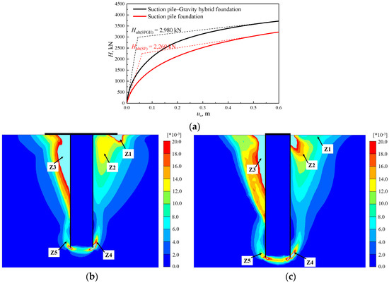
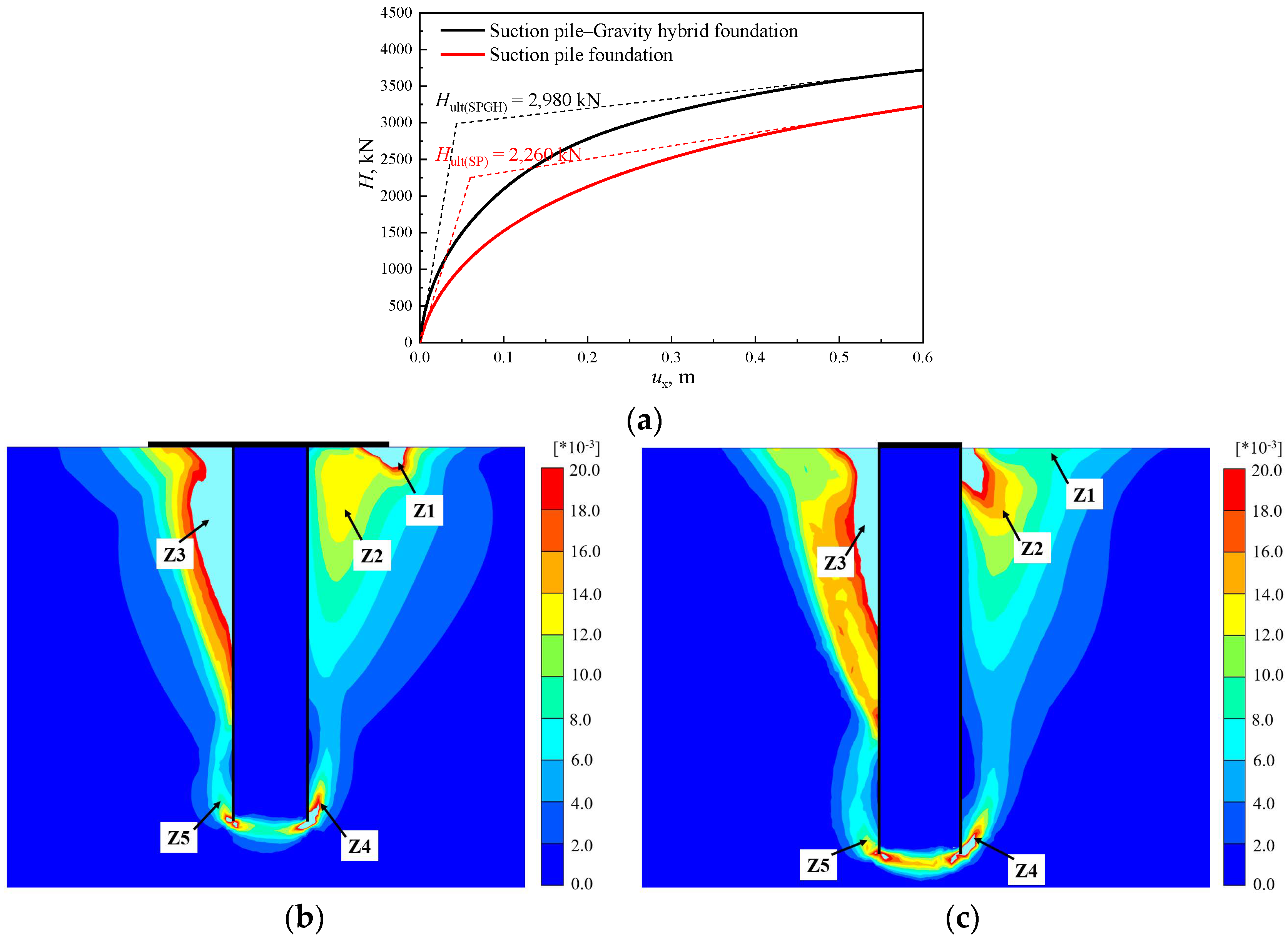
Figure 6 displays the bearing capacity curves and plastic strain of the SPGH foundation and SP foundation under horizontal loading in sand with Dr = 40%. As shown in Figure 6a, the tangent intersection method is used to determine the horizontal ultimate bearing capacity of the SPGH foundation [34]. The ultimate horizontal bearing capacities of SPGH and SP foundations are 2980 kN and 2260 kN. The existence of a gravity foundation increases the bearing capacity of the SPGH foundation by 31.86%; this indicates that the soil beneath the gravity foundation significantly contributes to the foundation’s horizontal bearing capacity. Figure 6b,c show that when SPGH and SP foundation reach the horizontal ultimate bearing capacity, both exhibit rotational failure, and their rotation centers are around 0.75Lp and 0.79Lp, respectively. Due to the influence of the gravity foundation, a significant plastic failure zone is formed in the Z1 region at the lower right side of the SPGH foundation in Figure 6b. When the SPGH foundation is under horizontal loading, a part of the load is directly transmitted through the gravity foundation–soil interface to the shallow soil layer (Zone Z1). This allows part of the horizontal load to be borne by passive earth pressure, resulting in a significant increase in the horizontal bearing capacity of the SPGH foundation. In addition, due to the stress concentration effect at the tip of the SP foundation, significant plastic deformation occurs at area Z2 in Figure 6c. The plastic failure at areas Z3 and Z4 is mainly due to the separation of pile–soil caused by the rotation of the foundations. The plastic strain at area Z5 is due to soil compression.
Figure 6.
Loading–displacement curve and plastic strain of the SPGH and SP foundations under horizontal loading. (a) Horizontal loading–displacement curves of SPGH and SP foundation. (b) Plastic strain of the SPGH foundation. (c) Plastic strain of the SP foundation.
3.1.3. Bending Moment Loading
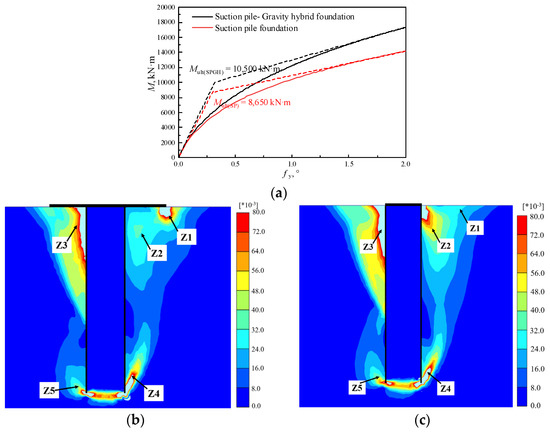
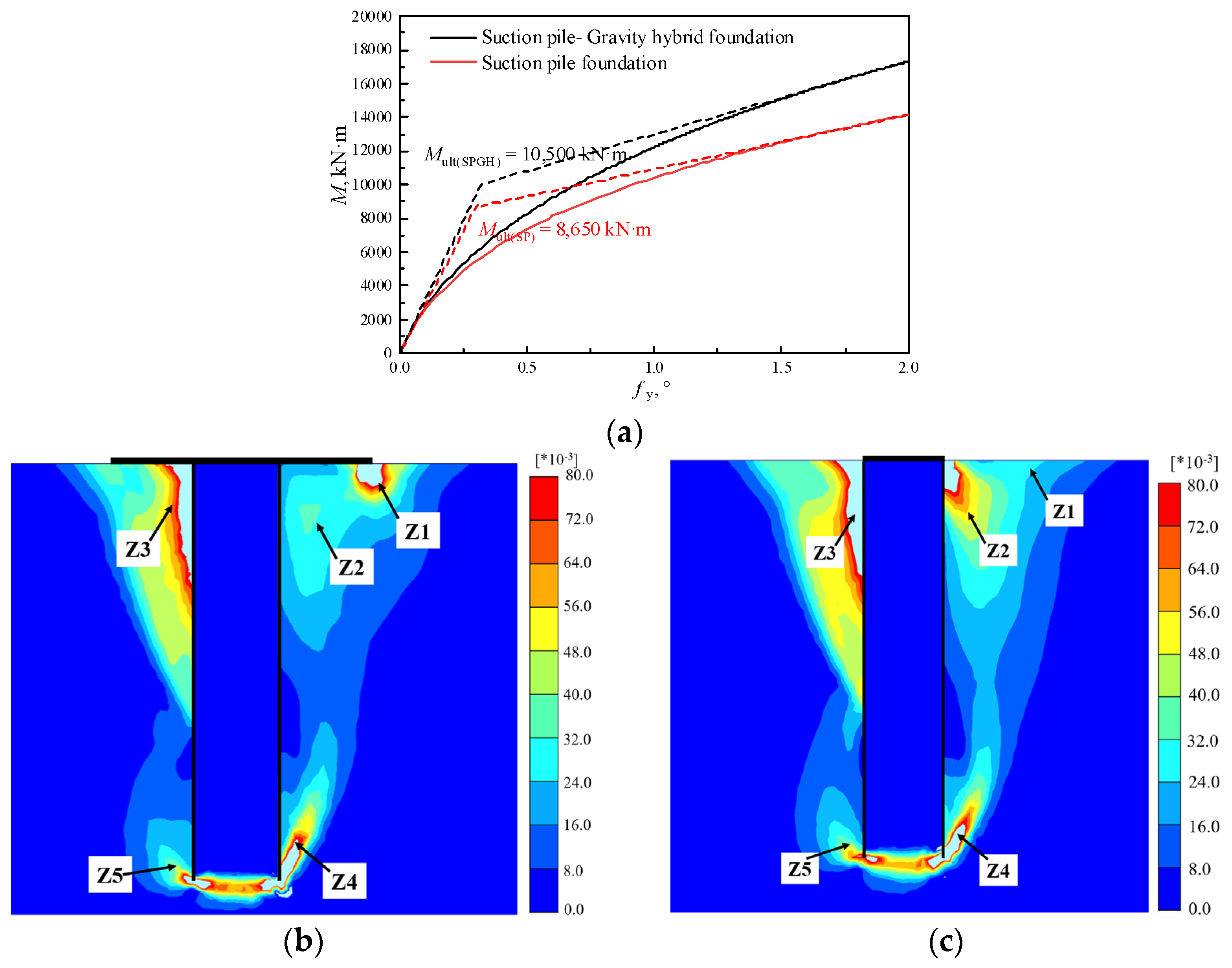
Figure 7 shows the bearing capacity curves and plastic strain of the SPGH foundation and SP foundation under bending moment loading in sand with Dr = 40%. As shown in Figure 7a, the ultimate bending moment-bearing capacities of SPGH and SP foundations are 10,500 kN·m and 8650 kN·m. Compared with the SP foundation, the bending moment-bearing capacity of the SPE foundation has increased by 21.39%. Figure 7b,c show that SPGH and SP foundations also exhibit rotational failure under bending moment loading, with their plastic strains similar to the failure mechanism observed under horizontal loading. It is worth noting that under bending moment loading, the rotation center of the SPGH and SP foundations consistently occurs near 0.66Lp and 0.68Lp.
Figure 7.
Loading–rotation curve and plastic strain of the SPGH and SP foundations under bending moment loading. (a) Bending moment loading–rotation angle curves of SPGH and SP foundation. (b) Plastic strain of the SPGH foundation. (c) Plastic strain of the SP foundation.
3.1.4. Torque Loading
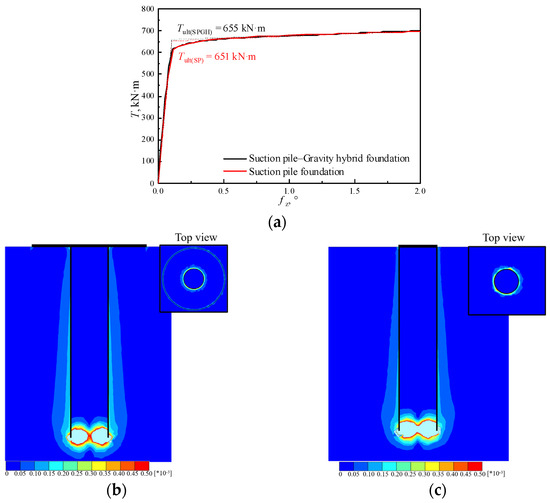
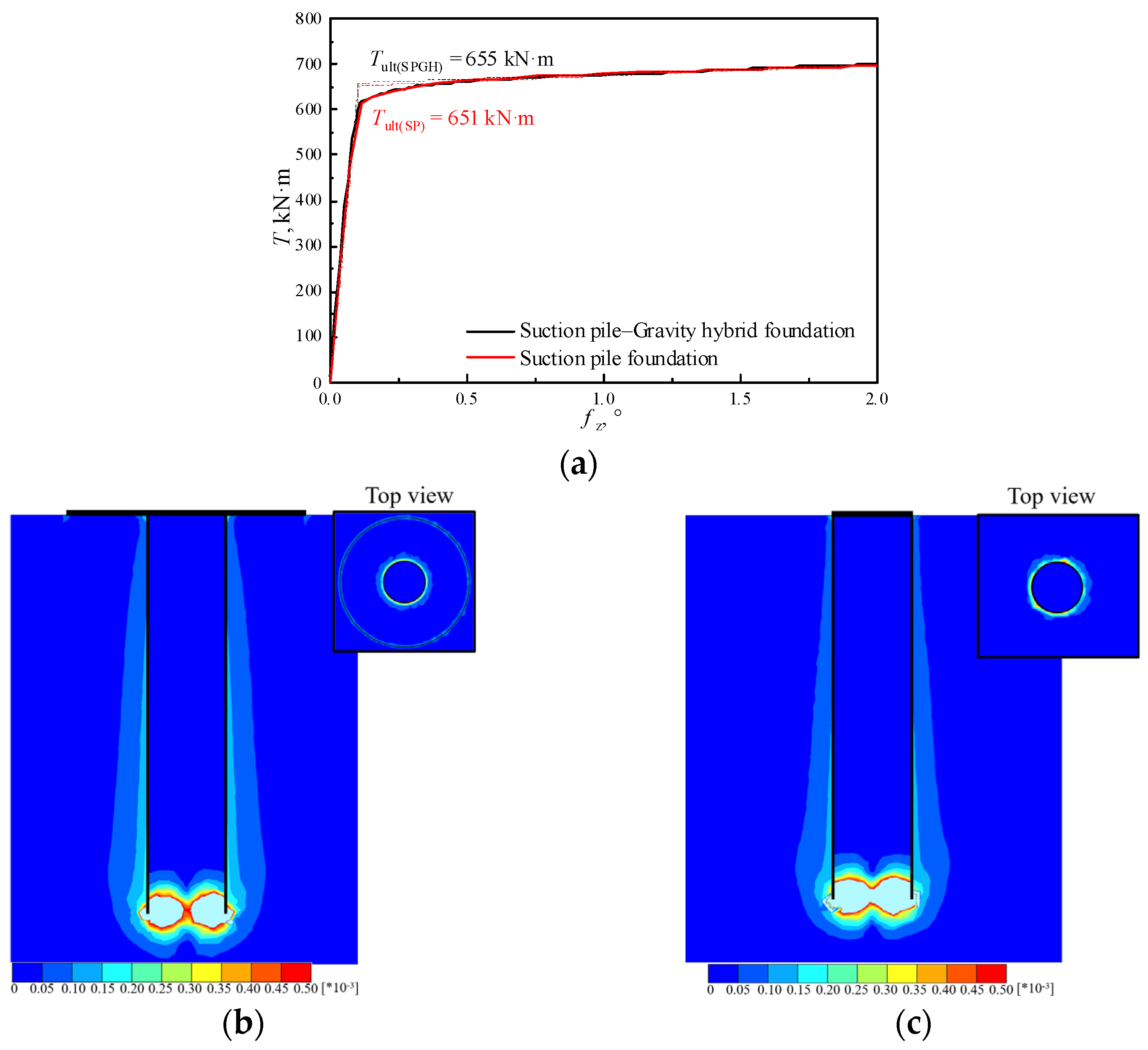
Figure 8 displays the bearing capacity curves and plastic strain of the SPGH foundation and SP foundation under torque loading in sand with Dr = 40%. As shown in Figure 8a, the ultimate torque-bearing capacities of SPGH and SP foundations are 700 kN·m and 696 kN·m. This indicates that without considering the effect of gravity, only the interface resistance between the suction pile foundation and soil provides the torque-bearing capacity of the foundations. Figure 8b,c show that the SPGH foundation and SP foundation have the same failure mode under ultimate torque loading, where plastic strain develops in the soil surrounding the suction pile foundation’s outer wall, while the internal soil exhibits no plastic strain. This is primarily because the effect of interface shear force leads to significant plastic strain between the outer wall of the suction pile and the soil. The soil inside the suction pile foundation rotates along with the foundation, resulting in almost no plastic strain. In addition, due to stress concentration effects at the contact area between the foundation end and the soil, significant plastic failure occurs in the soil surrounding the end of the suction pile foundation.
Figure 8.
Loading–rotation curve and plastic strain of the SPGH and SP foundations under torque loading. (a) Torque loading–rotation angle curves of SPGH and SP foundation. (b) Plastic strain of the SPGH foundation. (c) Plastic strain of the SP foundation.
3.2. Combination Loading
In complex marine environments, particularly under extreme conditions, foundations simultaneously endure combined loads from multiple directions. Additionally, during the service period of the SPGH hybrid foundation, the vertical bearing capacity is related to self-weight and uplift loads. Therefore, when the self-weight exceeds the uplift load, the foundation experiences a downward vertical load (−V); when the self-weight is less than the uplift load, the foundation experiences an upward vertical load (+V). This section employs the fixed-ratio probing loading method to investigate the failure envelope of SPGH foundation in sand with Dr = 40% under combined loads (H-M, H-V, M-V, H-T, M-T, T-V, where V represents both upward and downward vertical loads). The failure envelope curves are normalized using the uniaxial ultimate bearing capacities (Vult, −Vult, Hult, Mult, Tult). Based on these numerical simulation results, the normalized failure envelope curve formula of SPGH foundations under combined loading is derived.
3.2.1. Combined H-M Capacity
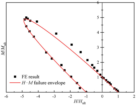
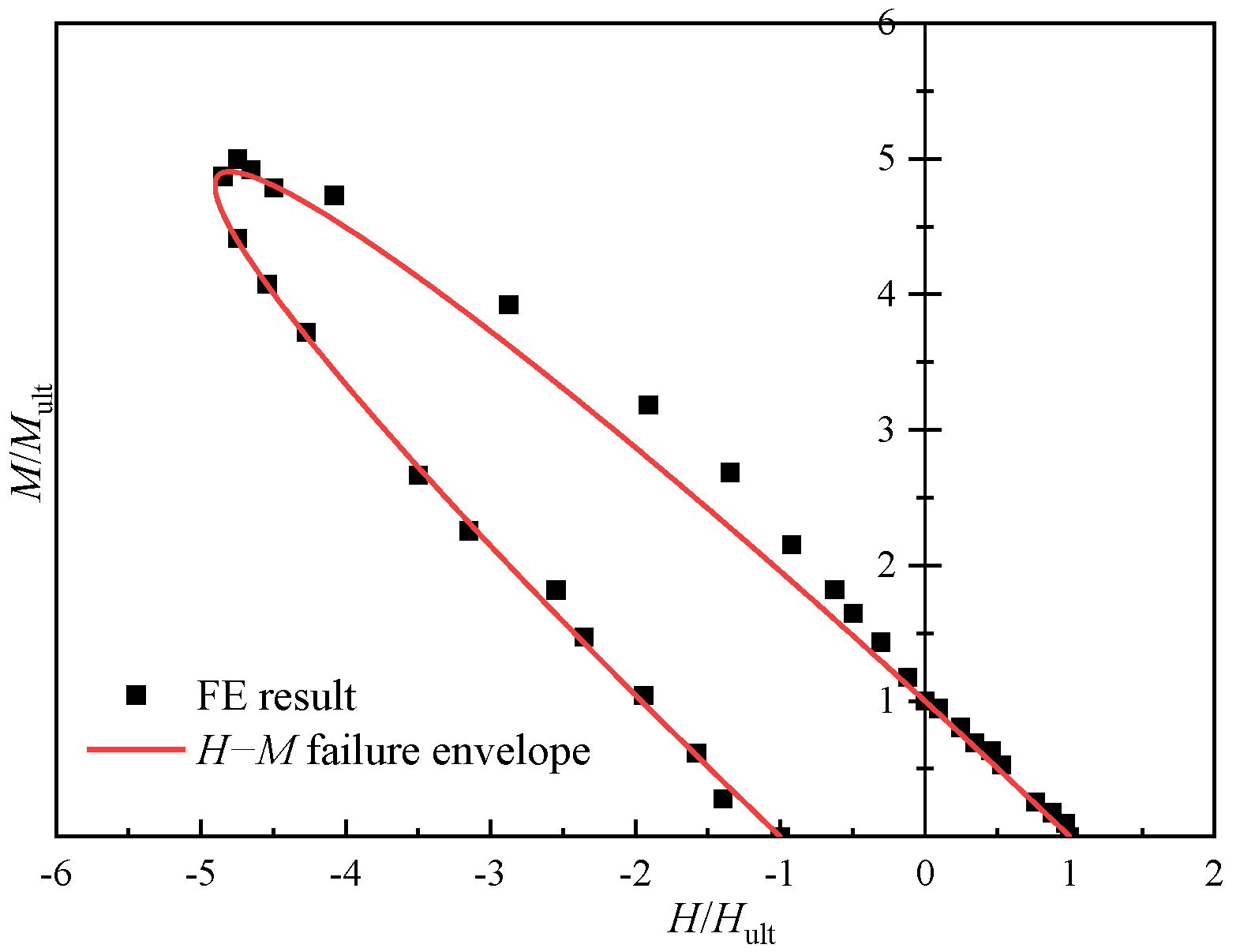
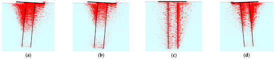
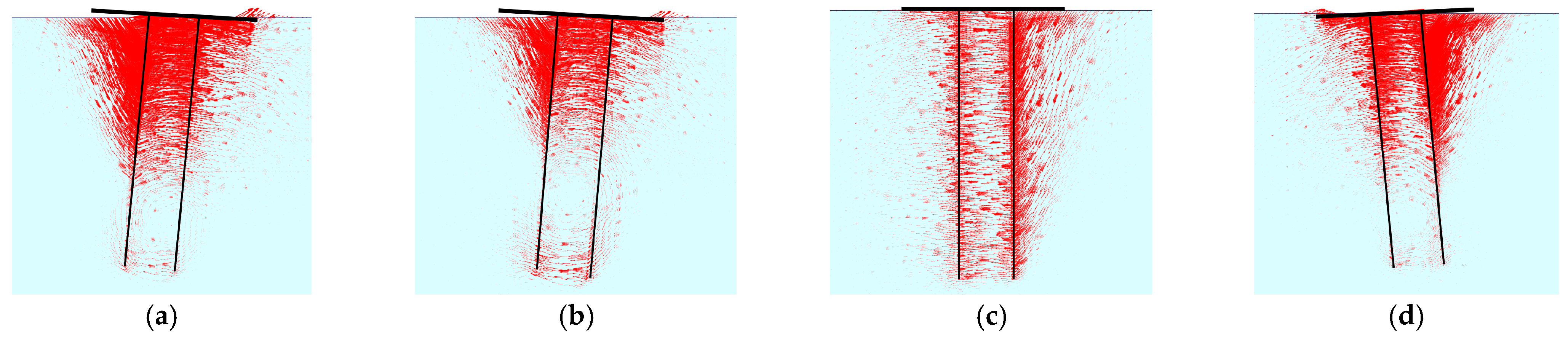
Figure 9 displays the failure envelope curve of an SPGH foundation under combined horizontal–bending moment (H-M) loading. As shown, the failure envelope exhibits typical coupled failure characteristics under H-M combined loading. It is noteworthy that the direction of horizontal loading leads to different bearing behaviors of the foundation. When both horizontal and bending moment loads are positive (horizontal load along the positive x-axis direction, bending moment load in the clockwise direction about the y-axis), the bending moment bearing capacity of the foundation gradually decreases as the horizontal load increases, until M = 0 kN·m, during which the peak bending moment capacity is M/Mult = 1, and the failure mechanism consistently remains rotational failure, as depicted in Figure 10a,b.
Figure 9.
Failure envelope curve under H-M loading.
Figure 10.
Displacement field of SPGH foundation under H-M loading at different times: (a) H/Hult = 1; (b) H/Hult = 0; (c) H/Hult = −4.87; (d) H/Hult = −1.
When the horizontal load is negative and the bending moment load is positive (horizontal load along the negative x-axis direction, bending moment load in the clockwise direction about the y-axis), the bending moment bearing capacity of the foundation gradually increases as the horizontal load increases. When the horizontal load H/Hult = −4.65 (where “-” denotes the direction of the horizontal load), the bending moment capacity reaches its peak value of M/Mult = 4.92, and the failure mechanism gradually shifts from rotational failure to translational failure, as illustrated in Figure 10b–d. Based on the results of the numerical simulations, the normalized failure envelope of the SPGH foundation under H-M combined loading can be expressed by Equation (1).
3.2.2. Combined H-V, M-V Capacity
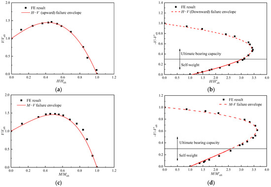
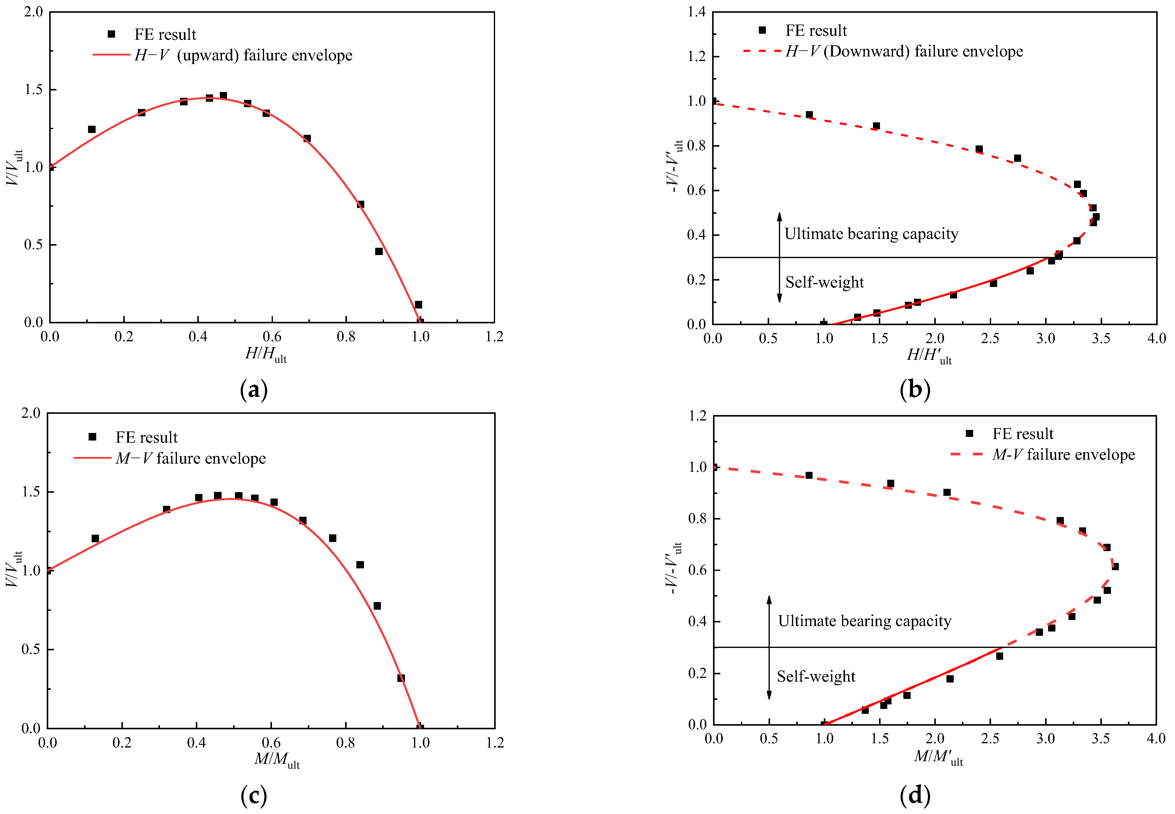
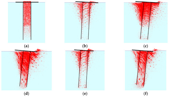
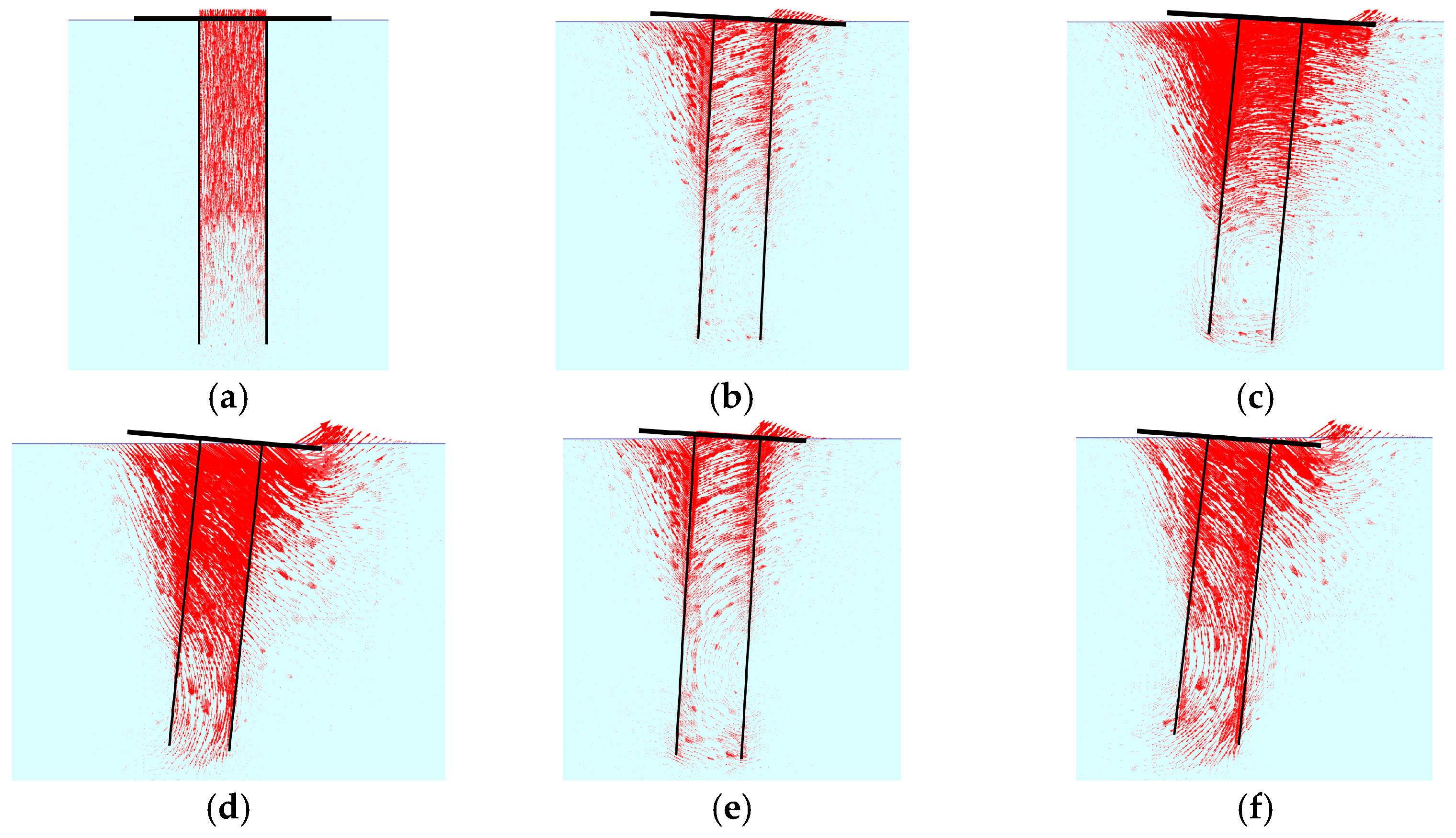
Figure 11 displays the failure envelope curves for SPGH foundations under horizontal and bending moment–vertical loads (H-V and M-V, upward and downward). As shown in Figure 11a, under combined horizontal and vertical uplift loading, the vertical bearing capacity of the foundation first increases and then decreases as the horizontal load gradually increases. This phenomenon can be attributed to the horizontal load inducing rotation in the SPGH foundation. This results in a significant increase in extra stress on the soil surrounding the foundation, which enhances the shear force between the foundation and soil, thereby improving the vertical uplift-bearing capacity of the SPGH foundation, as illustrated in Figure 12a,b. However, as the horizontal load continues to increase, soil failure occurs, causing the vertical uplift-bearing capacity of the SPGH foundation to decrease, as shown in Figure 12c. The failure envelope of the SPGH foundation under bending moment–vertical uplift load exhibits a similar shape to that under horizontal–vertical uplift load. In these cases, the loads induce foundation rotation, increasing the shear force between the foundation and soil, thereby enhancing the vertical uplift-bearing capacity, as shown in Figure 12e. When H/Hult = 0.53, the vertical uplift-bearing capacity of the foundation reaches a peak value at V/Vult = 1.46, representing a 46% increase in vertical uplift-bearing capacity. When M/Mult = 0.48, the vertical uplift-bearing capacity reaches a peak value at V/Vult = 1.48, representing a 48% increase.
Figure 11.
Failure envelope curves under H-V and M-V loading. (a) Failure envelope curves under H-V (upward) loading. (b) Failure envelope curves under H-V (downward) loading. (c) Failure envelope curves under M-V (upward) loading. (d) Failure envelope curves under M-V (downward) loading.
Figure 12.
Displacement field of SPGH foundation under H-V and M-V loading at different times: (a) H/Hult = 0 (upward); (b) H/Hult = 0.53 (upward); (c) H/Hult = 1 (upward); (d) H/Hult = 3.42 (downward); (e) M/Mult = 0.48 (upward); (f) H/Hult = 3.61 (downward).
Figure 11b,d display the failure envelope curves of the SPGH foundation under horizontal–vertical compressive load and bending moment–vertical compressive load. As −V′/−V′ult gradually increases, the horizontal and bending moment capacities of the foundation exhibit a trend of first increasing and then decreasing. This occurs because, within a certain range (where −V′/−V′ult for horizontal and bending moment loads are between 0 and 0.48, and 0 and 0.62, respectively), the vertical compressive load increases the normal stress at the gravity foundation and enhances the soil modulus and passive earth pressure, thereby improving the horizontal and bending moment-bearing capacity. Based on numerical simulation results, the normalized failure envelope of the SPGH foundation under combined H-V and M-V (upward and downward) loading can be expressed by the following equation.
3.2.3. Combined H-T, M-T Capacity
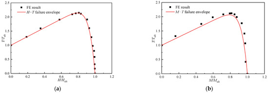
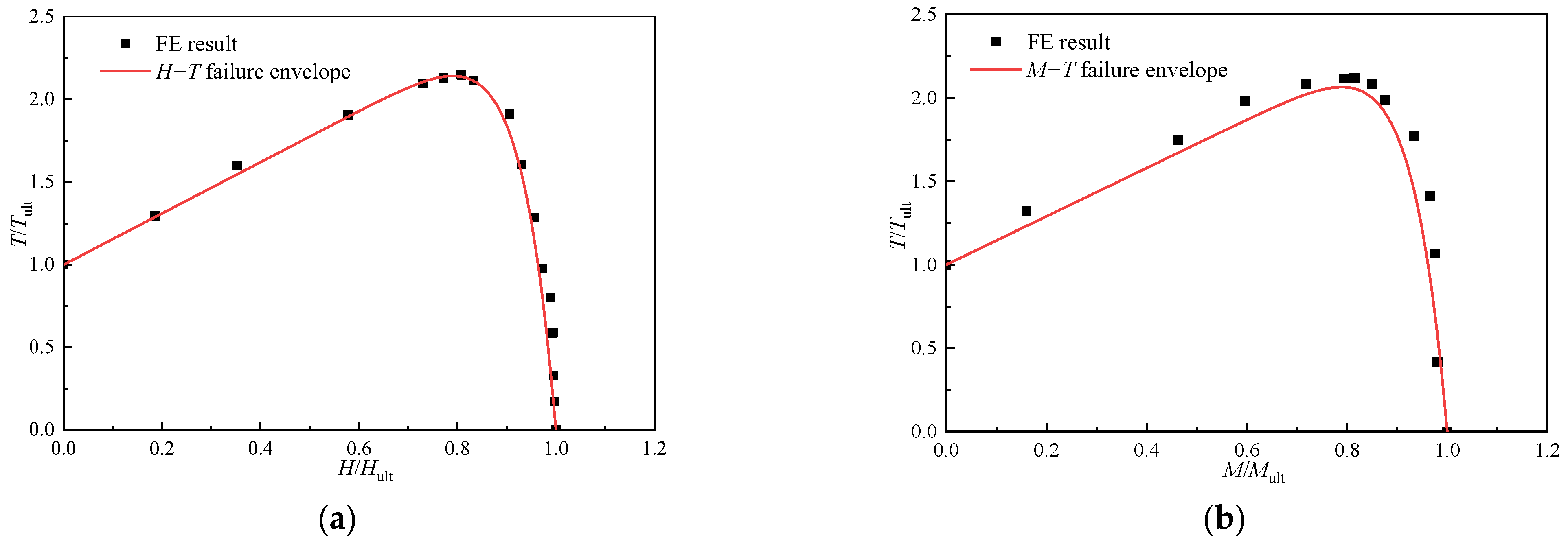
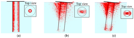
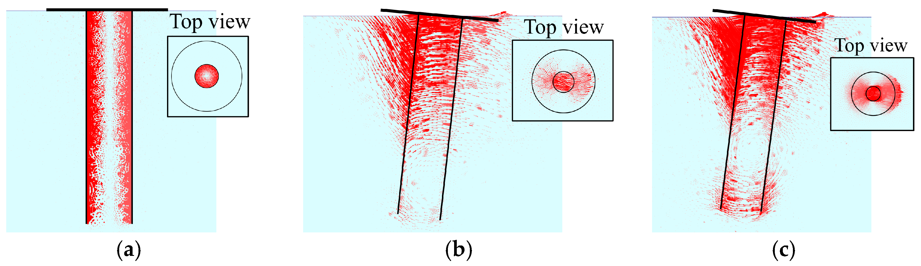
Figure 13 shows the failure envelope curves of SPGH foundations under horizontal– torque and bending moment–torque loads (H-T, M-T). As shown in Figure 13a,b, with the gradual increase in horizontal or bending moment loads, the torque-bearing capacity first increases and then rapidly decreases to 0, exhibiting a trend similar to that in Figure 11. This is because both torque and vertical uplift load-bearing capacity result from shear force between the foundation and soil. Consequently, they exhibit similar response characteristics under horizontal or bending moment loading. Figure 14 shows its displacement at different times. When H/Hult = 0.81, the torque-bearing capacity reaches its peak value at T/Tult = 2.15, a 115% increase. When M/Mult = 0.82, the torque-bearing capacity reaches peak value at T/Tult= 2.12, representing a 112% increase. Based on numerical simulation results, the normalized failure envelope of the SPGH foundation under combined H-T and M-T loads can be expressed by the following equation.
Figure 13.
Failure envelope curves under H-T and M-T loading. (a) Failure envelope curves under H-T. (b) Failure envelope curves under M-T.
Figure 14.
Displacement field of SPGH foundation under H-T and M-T loading at different times: (a) H/Hult = 0; (b) H/Hult = 0.81; (c) M/Mult = 0.82.
3.2.4. Combined V-T Capacity
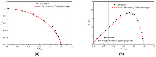
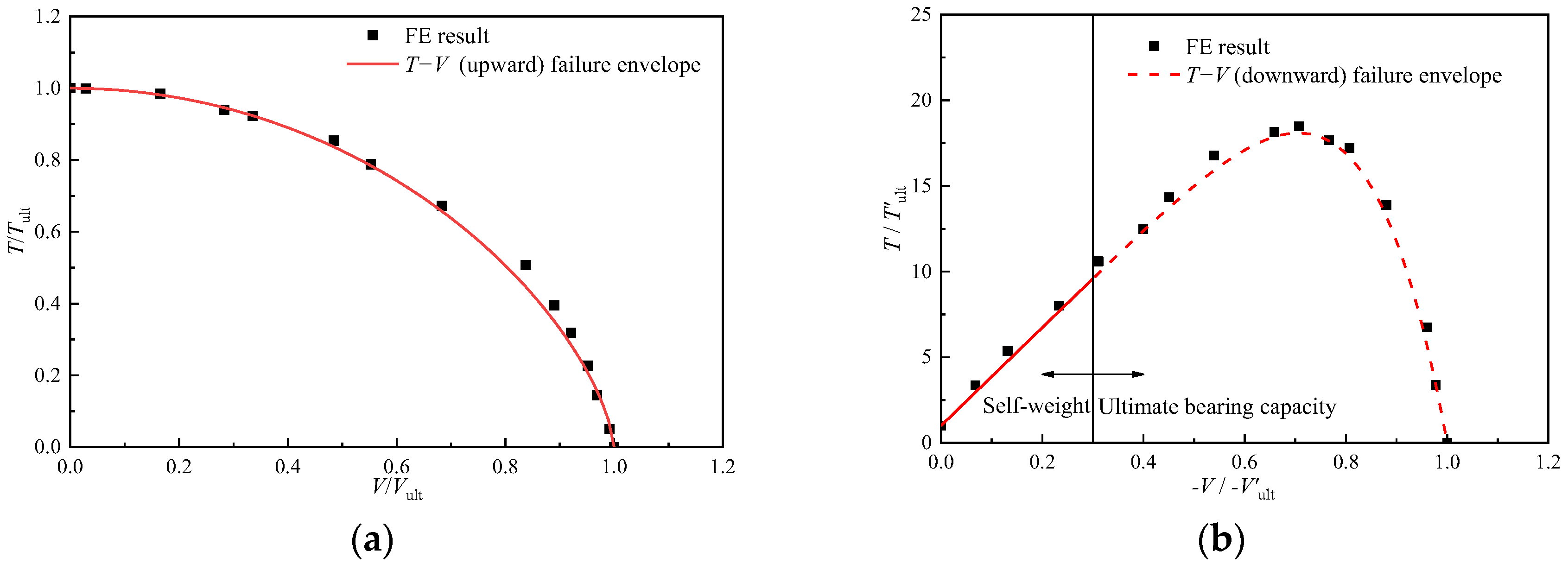
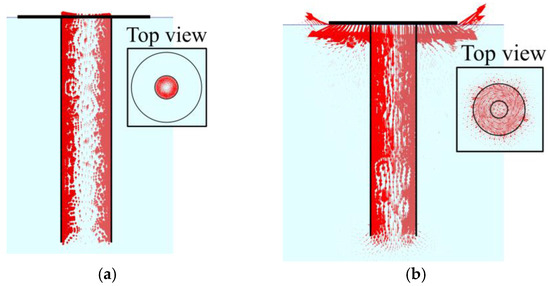
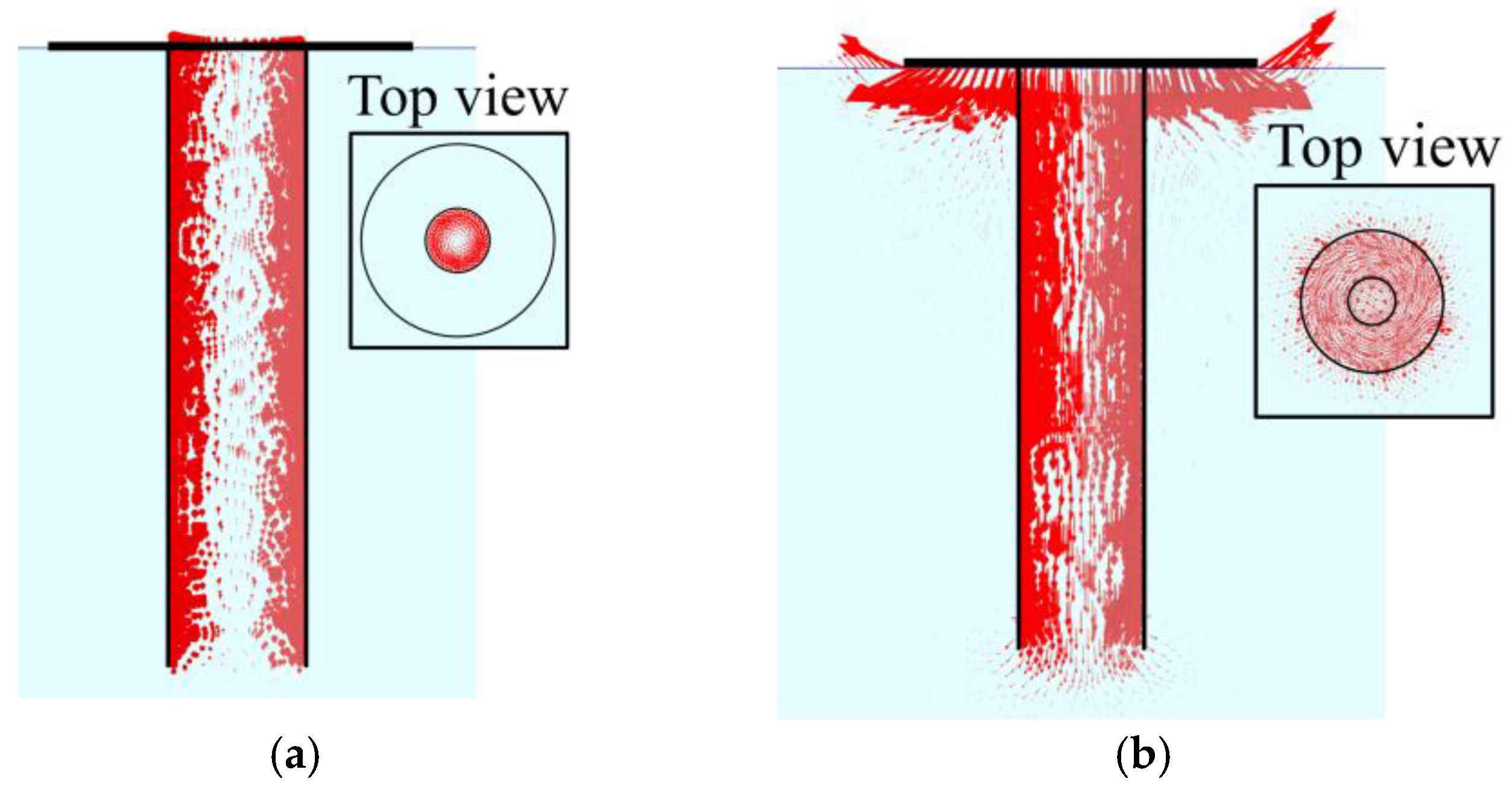
Figure 15 presents the failure envelope curves of the SPGH foundation under combined vertical (upward and downward)–torque loading. As shown, under the V(uplift)-T combined loading, the failure envelope curve exhibits clear coupled failure characteristics. As the vertical uplift load increases, the torque-bearing capacity gradually decreases. This phenomenon can be attributed to the fact that the failure mechanism for both vertical uplift and torque loads is shear failure between the foundation and soil. Consequently, these exhibit significant coupling. When the vertical load transitions to compressive loading (downward), an increase in vertical compressive load significantly enhances the torque-bearing capacity. This is attributable to the vertical compressive load increasing the normal stress of the soil, leading to a significant increase in the frictional resistance between the gravity foundation and the soil. Consequently, the torque-bearing capacity of the foundation is enhanced, as shown in Figure 16b. Based on the numerical simulation results, the normalized failure envelope of the SPGH foundation under combined V(upward and downforce)-T loading can be expressed by the following equation. It is worth noting that the failure envelope Equations (1)–(9) are empirical formulas derived from fitting numerical simulation data. The exponents in the equations serve as curve-fitting parameters, precisely describing the nonlinear shape of the envelope curve rather than specific physical quantities. Although individual exponents lack direct physical meaning, the envelope curve morphology determined by their combination macroscopically reflects the coupled strength characteristics of the SPGH foundation under combined loading. In addition, these formula parameters were determined for sand with Dr = 40%; recalibration is required when soil properties vary. Secondly, it applies only to the foundation with geometric proportions (LP/DP, DG/DP) similar to those in this study.
Figure 15.
Failure envelope curves under V(upward and downforce)-T loading. (a) Failure envelope curves under V(upward)-T. (b) Failure envelope curves under V(downward)-T.
Figure 16.
Displacement field of SPGH foundation under V (upward and downforce)-T loading at different times: (a) V/Vult = 0.5 (upward); (b) −V/−Vult = 0.3 (downward).
4. Conclusions
This study established the suction pile–gravity hybrid foundation and marine sand interaction model by using the Plaxis 3D finite element software. The Hardening Soil constitutive model was adopted to simulate the stress–strain behavior of sand. A systematic numerical analysis was conducted on the bearing characteristics of SPGH foundations in sand under uniaxial and multidimensional loading. The primary conclusions are as follows:
- Under pure vertical uplift or torque loading, both the SPGH and SP foundations exhibited typical interfacial shear failure modes. Their vertical uplift and torsional capacities were identical, with the gravity foundation in the SPGH foundation providing no additional interfacial resistance. Under pure horizontal or bending moment loading, both the SPGH and SP foundations exhibited rotational instability failure. The horizontal and bending moment capacities of the SPGH foundation increased by 31.86% and 21.39%, respectively. The soil beneath the gravity foundation significantly enhanced horizontal and bending moment-bearing capacity. The SPGH foundation demonstrates significant advantages in resisting horizontal and bending moment loads (due to inherent structural strength) and vertical uplift and torsional loads (from foundation self-weight). It can replace traditional suction pile foundations to optimize dimensions and reduce costs.
- The envelope curves at the H-V loading plane can be used to evaluate the bearing performance of the SPGH foundation under multi-directional loading, and the direction of vertical load (the relationship between vertical uplift load and foundation self-weight) has a significant impact on its bearing performance. In engineering design evaluations, the stability verification shall utilize the H-V failure envelope established in this paper, and the safety factors under vertical uplift (V) and downforce (-V) must be verified separately.
- The coupling effect under combined loading requires careful consideration, as it leads to a significant enhancement of the ultimate capacities (i.e., the maximum vertical capacity at the upward H-V envelope, the maximum horizontal capacity at the downward H-V envelope, etc.). This is mainly attributed to the dilatancy of sand under failure loads. Therefore, in actual engineering design, the load combination range that maximizes the overall safety margin should be optimized based on the complete failure envelope.
Limitations and Engineering Implications: This study is based on specific dimensions. The response of the SPGH foundation in other dimensions (varying LP/DP and DG/DP ratios) may exhibit significant variations. Therefore, the bearing capacity and failure envelope curves presented herein should not be directly extrapolated to other dimensions in actual engineering projects. Furthermore, the analysis primarily addresses short-term static loads and does not systematically consider the impact of long-term cyclic loading on static bearing capacity. Nevertheless, this work mechanistically verifies the foundation’s ability to synergistically mobilize shallow and deep soil layers to efficiently resist complex loads, providing conceptual support for its feasibility. In addition, the established failure envelope and empirical formula offer a preliminary quantitative framework for evaluating stability under complex loading conditions.
Author Contributions
Conceptualization, Y.C. and M.L.; methodology, Y.C. and M.L.; software, Y.C. and M.L.; validation, Y.C. and Z.H.; formal analysis, Y.C. and Z.H.; investigation, M.L. and F.Y.; resources, Y.C. and D.F.; data curation, Y.C. and F.Y.; writing—original draft preparation, Y.C. and M.L.; writing—review and editing, Y.C.; visualization, Y.C. and D.F.; supervision, D.F.; project administration, D.F.; funding acquisition, D.F. All authors have read and agreed to the published version of the manuscript.
Funding
The authors are supported by the National Natural Science Foundation of China (No. 42177122; No. 52271290; No. 42025702), the Young Experts of Taishan Scholars (No. tsqn202211071), and the Basic and Applied Basic Research Foundation of Guangdong Province (No. 2023A1515240026). This support is gratefully acknowledged.
Data Availability Statement
The data presented in this study are available upon request from the corresponding author.
Conflicts of Interest
Author Yangming Chen was employed by the China Power Engineering Consulting Group Co., Ltd. The remaining authors declare that the research was conducted in the absence of any commercial or financial relationships that could be construed as a potential conflict of interest.
Nomenclature
| DP | diameter of the suction pile foundation (m) |
| LP | suction pile length (m) |
| DG | diameter of the gravity foundation (m) |
| μ | sand interface coefficient (-) |
| φ | internal friction angle of sand (°) |
| q | deviatoric stress (kPa) |
| ε | axial strain ratio (%) |
| pref | reference confining pressure for triaxial tests (kN/m2) |
| E50ref | secant modulus at 50% of the ultimate load in the standard triaxial drained tests (kN/m2) |
| Eoedref | tangent stiffness modulus obtained from the consolidation tests (kN/m2) |
| Eurref | unloading and reloading modulus (kN/m2) |
| ψ | dilation angle of sand (°) |
| cref | cohesive force of soil (kN/m2) |
| m | power exponent related to the stiffness stress level (-) |
| G0ref | initial shear modulus under reference confining pressure pref (kN/m2) |
| γ0.7 | the shear strain level where the secant shear modulus is reduced to 70% of G0 (-) |
| σ′ | reference confining pressure for triaxial tests in Ottawa sand parameters (kN/m2) |
| e | void ratio (-) |
| γsat | unit soil weight below phreatic level (kN/m3) |
| Dr | relative density of soil (%) |
| V | load applied along the positive direction of the coordinate axes (kN) |
| −V | load applied along the negative direction of the coordinate axis (kN) |
| Vult | ultimate vertical load (kN) |
References
- Terzaghi, K. Theoretical Soil Mechanics; John Wiley Sons, Inc.: Hoboken, NJ, USA, 1943. [Google Scholar]
- Meyerhof, G.G. The Ultimate Bearing Capacity of Foundations. Géotechnique 1951, 2, 301–332. [Google Scholar] [CrossRef] [Scilit]
- Hansen, B.; Christensen, N.H.; Karafiath, L.L. Discussion of “Theoretical Bearing Capacity of Very Shallow Footings”. J. Soil Mech. Found. Div. 1969, 95, 1568–1573. [Google Scholar] [CrossRef] [Scilit]
- Hisham, T.E. Bearing Capacity and Settlement of Skirted Shallow Foundations on Sand. Int. J. Geomech. 2013, 13, 645–652. [Google Scholar]
- Fiumana, N.; Bienen, B.; Govoni, L.; Gourvenec, S.; Cassidy, M.J.; Gottardi, G. Combined loading capacity of skirted circular foundations in loose sand. Ocean. Eng. 2019, 183, 57–72. [Google Scholar] [CrossRef] [Scilit]
- Bransby, M.F.; Randolph, M.F. The effects of embedment on the undrained response of caisson foundations to combined loadings. Soils Found. 1999, 39, 19–33. [Google Scholar] [CrossRef] [Scilit] [PubMed]
- Yun, G.; Bransby, M.F. The horizontal-moment capacity of embedded foundations in undrained soil. Can. Geotech. J. 2007, 44, 409–424. [Google Scholar] [CrossRef] [Scilit]
- Gourvenec, S. Effect of embedment on the undrained capacity of shallow foundations under general loading. Géotechnique 2008, 58, 177–185. [Google Scholar] [CrossRef] [Scilit]
- Zhu, B.; Kong, D.Q.; Chen, R.P.; Kong, L.G.; Chen, Y.M. Installation and lateral loading tests of suction caissons in silt. Can. Geotech. J. 2011, 48, 1070–1084. [Google Scholar] [CrossRef] [Scilit]
- Liu, Y.; Guo, Y.; Ding, H.; Zhang, P. Failure envelopes of wide-shallow composite bucket foundation for offshore wind turbines in silty sand. Trans. Tianjin Univ. 2018, 24, 182–190. [Google Scholar] [CrossRef] [Scilit]
- Bienen, B.; Gaudin, C.; Cassidy, M.J.; Rausch, L.; Purwana, O.A.; Krisdani, H. Numerical modelling of a hybrid skirted foundation under combined loading. Comput. Geotech. 2012, 45, 127–139. [Google Scholar] [CrossRef] [Scilit]
- Lee, J.; Do, J. Effects of the Installation Method, Loading Condition, and Failure Mechanism on the Behavior of Suction Piles under Monotonic Horizontal Loading. J. Mar. Sci. Eng. 2021, 9, 1333. [Google Scholar] [CrossRef] [Scilit]
- Achmus, M.; Akdag, C.T.; Thieken, K. Load-bearing behavior of suction bucket foundations in sand. Appl. Ocean Res. 2013, 43, 157–165. [Google Scholar] [CrossRef] [Scilit]
- Park, J.S.; Park, D.; Yoo, J.K. Vertical bearing capacity of bucket foundations in sand. Ocean. Eng. 2016, 121, 453–461. [Google Scholar] [CrossRef] [Scilit]
- Wang, X.; Yang, X.; Zeng, X. Centrifuge modeling of lateral bearing behavior of offshore wind turbine with suction bucket foundation in sand. Ocean Eng. 2017, 139, 140–151. [Google Scholar] [CrossRef] [Scilit]
- Zhao, L.; Gaudin, C.; O’loughlin, C.D.; Hambleton, J.P.; Cassidy, M.J.; Herduin, M. Drained capacity of a suction caisson in sand under inclined loading. J. Geotech. Geoenviron. Eng. 2019, 145, 04018107. [Google Scholar] [CrossRef] [Scilit]
- Zhu, B.; Gao, D.; Chen, Y.M. Geomembrane tensions and strains resulting from differential settlement around rigid circular structures. Geotext. Geomembr. 2009, 27, 53–62. [Google Scholar] [CrossRef] [Scilit]
- Cheng, L.; Hossain, M.S.; Hu, Y.; Kim, Y.H.; Ullah, S.N. Failure envelope of suction caisson anchors subjected to combined loadings in sand. Appl. Ocean Res. 2021, 114, 102801. [Google Scholar] [CrossRef] [Scilit]
- Kim, S.; Choo, Y.W.; Kim, D.S. Pullout capacity of horizontally loaded suction anchor installed in silty sand. Mar. Georesour. Geotechnol. 2016, 34, 87–95. [Google Scholar] [CrossRef] [Scilit]
- Peng, Y.; Yin, Z.Y. Micromechanical analysis of suction pile-granular soil interaction under inclined pulling load of mooring line: Mooring depth effect. Mar. Struct. 2023, 92, 103499. [Google Scholar] [CrossRef] [Scilit]
- Ibsen, L.B.; Larsen, K.A.; Barari, A. Calibration of Failure Criteria for Bucket Foundations on Drained Sand under General Loading. J. Geotech. Geoenviron. Eng. 2014, 140, 04014033. [Google Scholar] [CrossRef] [Scilit]
- Bransby, M.F.; Randolph, M.F. Cabined loading of skirted foundations. Géotechnique 1998, 48, 637–655. [Google Scholar] [CrossRef] [Scilit]
- Wu, K.; Luan, M.T.; Fan, Q.L.; Wang, Z.Y. ·Failure envelopes of bucket foundation subjected to combined loads. Chin. J. Geotech. Eng. 2008, 30, 574–580. [Google Scholar]
- Gourvenec, S.; Randolph, M. Effect of Strength Non-Homogeneity on the Bearing Capacity of Circular Skirted Foundations Subjected to Combined Loading. In Proceedings of the 12th (2002) International Offshore and Polar Engineering Conference, Kitakyushu, Japan, 26–31 May 2002. [Google Scholar]
- Hung, L.C.; Kim, S.R. Evaluation of combined horizontal-moment bearing capacities of tripod bucket foundations in undrained clay. Ocean. Eng. 2014, 85, 100–109. [Google Scholar] [CrossRef] [Scilit]
- Zdravkovic, L.; Potts, D.M.; Jardine, R.J. A Parametric Study of the Pull-out Capacity of Bucket Foundations in Soft Clay. Géotechnique 2001, 51, 55–67. [Google Scholar] [CrossRef]
- Randolph, M.F.; House, A.R. Analysis of Suction Cassion Capacity in Clay. In Proceedings of the Offshore Technology Conference 2002 (OTC 02), Houston, TX, USA, 6–9 May 2002; p. OTC-14236-MS. [Google Scholar]
- Li, X.; Wu, Z.; Su, D.; Zhang, L. Reliability analysis of offshore monopile foundations considering multidirectional loading and soil spatial variability. Comput. Geotech. 2024, 166, 106045. [Google Scholar] [CrossRef] [Scilit]
- Houlsby, G.T.; Byrne, B.W. Design procedures for installation of suction caissons in sand. Geotech. Eng. 2005, 158, 135–144. [Google Scholar] [CrossRef]
- Zhang, Q.; Tang, G.; Lu, L.; Yang, F. Scour protections of collar around a monopile foundation in steady current. Appl. Ocean Res. 2021, 112, 102718. [Google Scholar] [CrossRef] [Scilit]
- Rui, S.; Wang, L.; Zhou, Z.; Jostad, H.P.; Guo, Z. Bearing performance of a novel caisson-plate gravity anchor. Geotechnique 2024, 75, 686–697. [Google Scholar] [CrossRef] [Scilit]
- Ramirez, J.; Badanagki, M.; Rahimi Abkenar, M.; ElGhoraiby, M.A.; Manzari, M.T.; Dashti, S.; Barrero, A.; Taiebat, M.; Ziotopoulou, K.; Liel, A. Seismic Performance of a Layered Liquefiable Site: Validation of Numerical Simulations Using Centrifuge Modeling. In Geotechnical Frontiers 2017; Geotechnical Special Publication 281; ASCE: Reston, VA, USA, 2017. [Google Scholar]
- Fan, W.; Yuan, W. Numerical simulation and analytical modeling of pile-supported structures subjected to ship collisions including soil–structure interaction. Ocean Eng. 2014, 91, 11–27. [Google Scholar] [CrossRef] [Scilit]
- Kim, S.R.; Hung, L.C.; Oh, M. Group effect on capacities of tripod bucket foundations in undrained clay. Ocean Eng. 2014, 79, 1–9. [Google Scholar] [CrossRef] [Scilit]

Disclaimer/Publisher’s Note: The statements, opinions and data contained in all publications are solely those of the individual author(s) and contributor(s) and not of MDPI and/or the editor(s). MDPI and/or the editor(s) disclaim responsibility for any injury to people or property resulting from any ideas, methods, instructions or products referred to in the content. |
© 2026 by the authors. Licensee MDPI, Basel, Switzerland. This article is an open access article distributed under the terms and conditions of the Creative Commons Attribution (CC BY) license.