


Abstract
Under extreme heterogeneous loading conditions in the deep sea, obtaining well-preserved and stratigraphically coherent cores is a critical challenge that requires urgent resolution. Current methods cannot directly determine the preservation of core stratigraphic information or the sampling behaviour of drill bits through experimentation. Consequently, a new evaluation method for angular velocity-based stratigraphic preservation, which is grounded in Discrete Element Method (DEM) theory, is proposed. Simulation modelling uses the Hertz–Mindlin contact model to construct a multi-scale geotechnical–drill string numerical coupling model. The drill string structure is simplified while incorporating actual geometric dimensions and material properties. By simulating and extracting particle angular velocity data under various operating conditions, a correlation is established between particle motion characteristics and the stratigraphic preservation status. Experiments were conducted on a customised drilling rig platform using specimens with deep-sea geomechanical properties consistent with the simulations. Drilling tools with multiple inner diameter specifications were configured, and multiple variable combinations of the rotational speed and feed rate were set. The degree of bedding preservation in the sampled cores was recorded synchronously. The study clarified the relationship between particle angular velocity and bedding preservation, identifying the influence patterns of parameters such as the tool inner diameter, rotational speed, and feed rate on bedding preservation. Results indicate that when the rotational speed exceeds 200 rpm and the feed rate falls below 0.018 m/s, stratigraphic distortion significantly increases; the drill bit inner diameter exhibits a non-linear negative correlation with core disturbance. This study provides theoretical underpinnings and experimental evidence for multi-parameter process optimisation in maintaining stratigraphic integrity during deep-sea submersible coring operations.
1. Introduction
Deep-sea drilling represents the “final ten centimetres” technology for decoding deep-Earth material cycles and assessing resource reserves. The in situ fidelity of its sampled core stratigraphy directly determines the reliability of subsequent stratigraphic sequence reconstruction, pore flow parameter calibration, and resource estimation. With the widespread deployment of the manned submersible Jiaolong, the interdisciplinary frontier technology of deep-diving-enabled deep-drilling for submersible core sampling has emerged as a critical operational capability requiring urgent enhancement. Achieving ‘low-disturbance’ sampling under extreme temperature–pressure conditions, low rock strength, and high stress gradients—while resolving stratigraphic disturbance during coring—has become a focal point in deep-sea science and engineering. The International Ocean Discovery Programme (IODP) has established that core disturbance readily causes sequence distortion during sampling of weakly cemented deep-sea sediments. Domestic scholars have also conducted research on core disturbance progression, data sharing, and disturbance control techniques in oceanic scientific drilling, providing theoretical and practical references for low-disturbance deep-sea sampling [1,2,3,4]. As a vital deep-sea exploration platform, China’s manned submersible Jiaolong has deployed its drilling and sampling system across multiple expeditions, acquiring high-value cores that have significantly supported major missions and scientific research. However, current core sampling practices, particularly for low-cementation deep-sea rocks, have not sufficiently considered the impact of coring disturbance on sequence preservation. The quality of sequence preservation may introduce biases into resource estimation calculations, affecting the economic viability and safety of extraction plans. Previous studies, integrating IODP core data, systematically reviewed the intrinsic relationship between deep-sea sedimentary sequence preservation and coring disturbance. Building upon insights from IODP studies, these works explored techniques for controlling coring disturbance in weakly cemented rocks [5,6]. The Discrete Element Method (DEM), owing to its advantages in particle stratification micro-scale simulation analysis, holds promise for further elucidating the mechanisms of coring disturbance and addressing the challenges of observing and evaluating core sequence preservation.
In recent years, scholars worldwide have conducted extensive research on DEM applications, drilling technology optimisation, and stratigraphic evolution analysis. In numerical simulation, Professor Graham G.W. Mustoe’s discrete element cementation model has advanced the mesoscale analysis of elastic materials [7]. Yang Zhaozhong and colleagues employed the block discrete element method to simulate fracture propagation in hydraulic fracturing, providing methodological references for the mesoscale evolution analysis of stratified rock masses [8]. Yang Zhenwei et al. investigated the damage mechanisms of layered shale under ultrasonic vibration through DEM simulations [9]. Shan’s team utilised the coupled finite–discrete element method to analyse the effects of interfacial slip and permeability on hydraulic fracturing, deepening the numerical research on stratigraphic interface characteristics [10]. In experimental and engineering applications, Japan’s JAMSTEC deep-sea drilling testbed can simulate a 5000-m water pressure environment but struggles to capture microscopic particle motion and mesoscale stratigraphic evolution [11]. Ren Yugang’s research on the small-diameter drill bit drilling mechanisms for deep-sea submersibles has established technical foundations for precision drilling in deep-sea environments [12]. Meanwhile, the application of the Discrete Element Method (DEM) in sampling disturbance studies has yielded valuable insights. Wang Tangyao utilised DEM to investigate the meso-mechanical properties of black shale [13], while Bo-Wen S. et al. simulated the unloading failure behaviours of transversely isotropic shale [14]. Weng Haoyang employed DEM to analyse the rock failure mechanisms and instability criteria in wellbore walls [15]. In lunar soil sampling, Hu Dingkun’s quantification of the disturbance ranges during drilling [16], Xie Lanlan’s research on disturbance dynamics [17], Gao Xingwen’s exploration of sequence preservation sampling techniques [18], and Liu Tianxi’s DEM study on drilling dynamics [19] collectively provide referenceable research approaches for disturbance control and sequence preservation in deep-sea core sampling. Although these studies have made progress in discrete element cementation models and heterogeneous sedimentary response, the lack of a unified quantitative framework based on DEM particle motion states has resulted in insufficient meso-theoretical foundations for drilling parameter optimisation, with notable gaps remaining in meso-level observation, quantitative evaluation, and model validation.
This study has established a quantitative, explicit correlation between particle angular velocity and sequence preservation, elucidating the micro-mechanisms by which key parameters such as the drill string bore diameter and rotational speed influence stratigraphic fidelity. It provides micro-theoretical support for optimising drilling parameters. Addressing critical technical bottlenecks in deep-sea core sampling—such as the inability to quantify stratigraphic fidelity and the lack of a theoretical basis for parameter optimisation in deep-diving equipment like the Jiaolong submersible—this research overcomes technical challenges in precisely controlling stratigraphic fidelity under extreme conditions. The findings can be directly applied to process optimisation and performance upgrades of deep-sea drilling systems, effectively enhancing the efficiency of acquiring high-fidelity cores. This provides high-quality in situ samples for deep-Earth scientific exploration and detailed marine resource assessment. Addressing the technical challenge of sequence preservation in deep-sea core sampling, this study introduces the Discrete Element Method (DEM) to analyse deep-sea drilling and sampling processes. It innovatively proposes a stratigraphic fidelity evaluation method based on particle angular velocity, establishing a multi-scale numerical model for soil–rock particle–drill string coupling. This model clarifies the quantitative relationship between particle instantaneous angular velocity and sequence preservation levels. Systematically investigating the coupled effects of multiple parameters—including the drill string inner diameter, rotational speed, and feed rate—alongside optimisation strategies, the study identified optimal process parameter combinations validated through experimental testing. This establishes a comprehensive research framework spanning from micro-mechanisms to macro-processes.
2. EDEM Numerical Model Construction and Stratification Evaluation Method
2.1. Construction of Deep-Sea Rock–Drill Tool Coupling Model
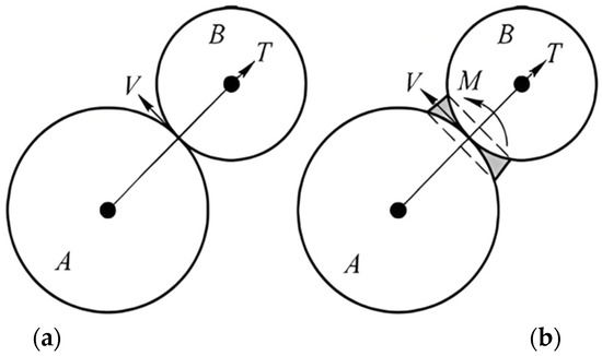
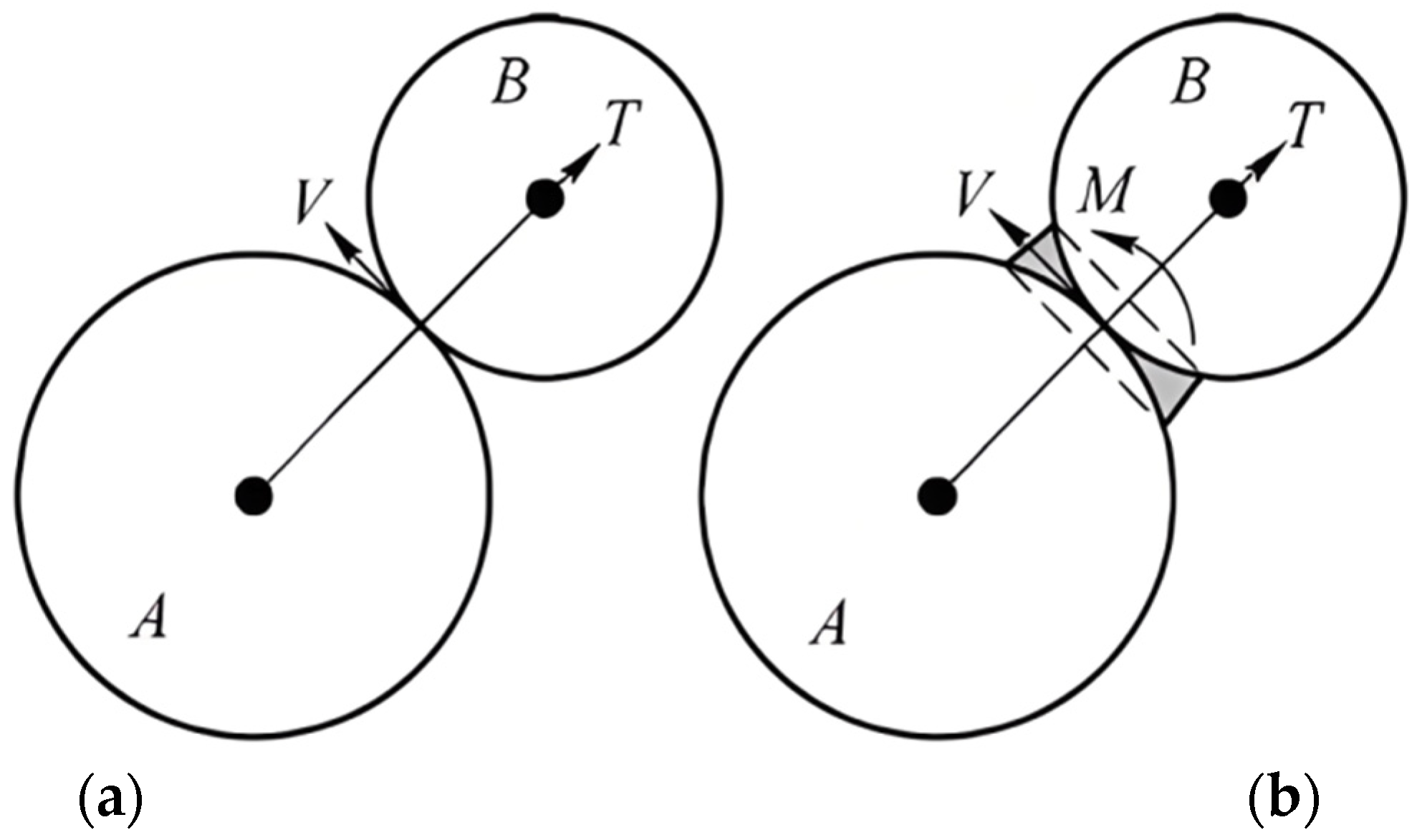
EDEM (2024) is high-performance CAE simulation software based on the discrete element method. Using EDEM, an integrated three-dimensional solid model of the “PDC drill bit–drill pipe–core barrel” was constructed. The material parameters of the drilling tools were derived from actual deep-sea steel, with an elastic modulus of 210 GPa, a Poisson’s ratio of 0.3, and a density of 7850 kg/m3. The rock mass was discretized as a cohesive aggregate of circular particles constrained by rigid planar walls. Parallel cohesion, which is capable of synchronously transferring forces and moments, was employed between particles (Figure 1b). Compared to the contact bond model (Figure 1a), this approach more accurately reflects the micro-scale mechanical characteristics of deep-sea rocks, which exhibit low cementation and high internal friction angles [20,21,22,23].
Figure 1.
Particle element bonding models in the discrete element model. (a) Contact bonding model; (b) parallel bonding model.
As shown in Figure 1b, the parallel bond between particle elements can be conceptualised as a set of springs uniformly distributed across a rectangular cross-section. The normal (σ) and tangential (τ) contact stresses satisfy Equation (1). Once either the normal stress or the tangential stress exceeds the parallel bond strength, the bond fails, resulting in the failure of the solid rock stratum [24].
where T is the normal force, M is the bending moment, A is the cross-sectional area, I is the moment of inertia, is the contact average radius, and V is the tangential force.
The EDEM contact model directly determines the consistency between simulation results and real physical processes by defining contact forces between particles and geometries. This study employs a parallel bonding contact model to construct a coupled discrete element model for deep-sea drilling. While this model effectively characterises the bonding and failure characteristics between rock particles, it possesses inherent limitations: Firstly, the model relies on idealised assumptions, such as uniform bonding and consistent strength between particles, without accounting for the surface irregularities and heterogeneity of deep-sea rock particles. This readily leads to idealised failure patterns. Secondly, particle size scaling readily induces DEM artefacts. Actual deep-sea rock particles are significantly smaller than the 1–3 mm range used in modelling. Scaling alters contact probabilities and force transmission pathways, exacerbating scale effects. Modelling requires calibration of key parameters such as particle density and Poisson’s ratio. Particle size distribution is determined by sieving rock samples, employing a continuous gradient distribution of 1–3 mm to match natural characteristics with a uniformity coefficient of 2.8 and curvature coefficient of 1.1. Beyond the specific gravity and diameter, all other parameters must be adjusted to match deep-sea rock properties of a high internal friction angle and low cohesion.
Poisson’s ratio constitutes a core parameter in discrete element modelling, requiring prioritised calibration to establish a benchmark value for rock materials. An increase in the shear modulus elevates the elastic modulus, normal force, and tangential force. To ensure computational accuracy, the calculation step size may be reduced, though this necessitates balancing precision with efficiency and simulating outcomes with computational cost. The recovery coefficient correlates with normal damping force. Based on contact force control and computational efficiency, this study employs a low recovery coefficient and high normal damping force. The static friction coefficient defines the tangential force sliding threshold. Considering deep-sea rock compactness, a relatively high internal friction angle was selected to reflect reality. Full parameter matching was ultimately achieved through laboratory calibration experiments and modelling experience, mitigating limitations. Relevant results are presented in Table 1.
Table 1.
Deep-sea rock particle parameter matching.
This study employs collaborative modelling using SolidWorks (2024) and EDEM simulation software to construct and simulate multibody coupled models for core components—the drill bit, drill pipe, and core barrel—in deep-sea drilling operations. During modelling, rock particle geometric features and mechanical parameters calibrated through standard testing were fully integrated. Based on discrete element method theory, a discrete element simulation model capable of accurately reflecting the dynamic interaction between the drill string and rock was established. The overall structure and interaction relationships of the model are shown in Figure 2. This model visually recreates the dynamic interaction between drilling tools and rock particles during rotation and cutting phases, clearly demonstrating particle compression, sliding, and fragmentation during core barrel retrieval, as well as the real-time evolution of core bedding patterns throughout drilling operations. It also enables real-time acquisition and precise extraction of key physical parameters such as particle angular velocity, contact forces, and displacement. This establishes a robust and visualizable simulation foundation for subsequent quantitative analysis of core disturbance levels under multi-parameter combinations (e.g., bit rotational speed, feed rate, and borehole diameter) and research into deep-sea core bedding preservation mechanisms [25,26,27,28,29].
Figure 2.
Establishment of a discrete element model for drill string–rock interaction.
To validate the suitability and accuracy of the constructed discrete element model for deep-sea rock drilling processes, this study conducted systematic comparative verification between simulation results and physical experimental data using a customised laboratory deep-sea rock drilling test platform. Considering actual deep-sea drilling conditions, standard operating parameters of 260 revolutions per minute, a feed rate of 0.036 m per second, and a drill hole diameter of 60 mm were selected. Cutting forces, torque, and core bedding fracture depth data were simultaneously collected and compared throughout the drilling process. Results indicate simulated cutting forces ranged from 8.2 to 9.5 kN, with measured values between 8.0 and 9.3 kN. Simulated torque values were 125–140 Nm, while measured values were 120–138 Nm, with average relative errors of merely 3.8% and 4.2% respectively. This fully demonstrates the model’s capability to accurately reproduce mechanical response characteristics and bedding evolution patterns observed in actual drilling operations, providing a reliable numerical simulation foundation for subsequent research.
Addressing concerns regarding the DEM model’s robustness to parameter variations, this study specifically conducted sensitivity analysis and uncertainty quantification for core parameters. Considering the low cohesion and brittle nature of deep-sea rocks, key parameters governing rock mechanical behaviour—including the elastic modulus, static and dynamic friction coefficients, and cohesion strength—were selected. Referencing the measured distribution range of natural deep-sea rock parameters, a reasonable fluctuation range of ±10% was established to systematically analyse the impact of parameter variations on model outputs. Statistical results indicate that when core parameters fluctuate within the aforementioned range, the relative deviation of key model outputs—such as cutting force and torque—remains below 5%. Furthermore, uncertainty quantification reveals that the coefficient of variation in model outputs is controlled within 3%. This outcome fully demonstrates the model’s robust stability against parameter variations, effectively mitigating potential analytical biases from parameter fluctuations. It further safeguards the scientific validity and reliability of subsequent multi-parameter coupling optimisation and sequence retention mechanism research outcomes.
2.2. Angular Velocity-Based Core Particle Disturbance Mechanism
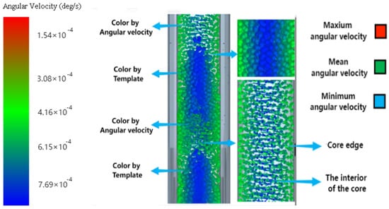
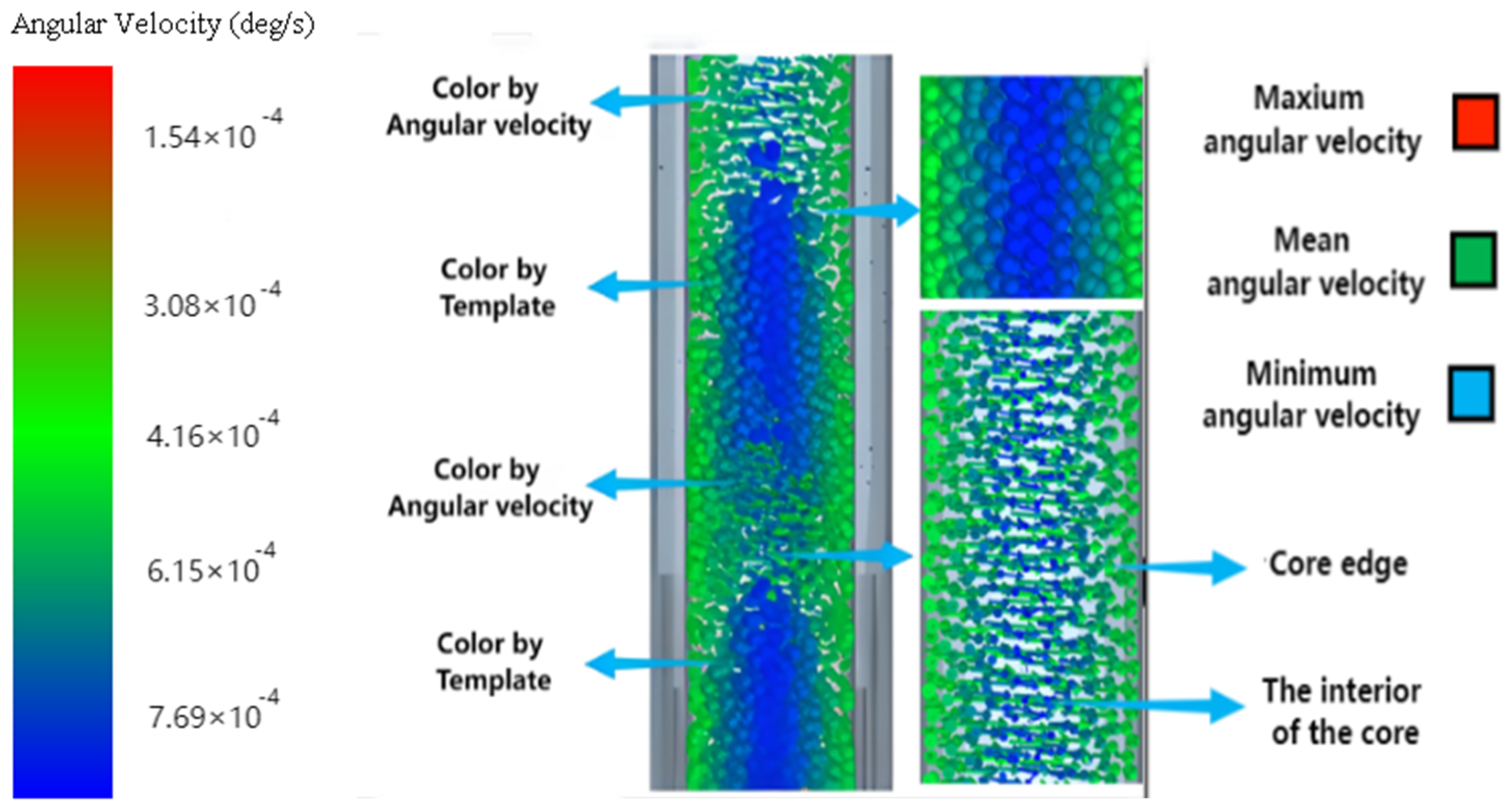
Particle disturbance is a microscopic process that leads to the destruction of stratified structures. Angular velocity, as a key parameter characterising particle rotation, drives the relative displacement of particles and reveals the intrinsic relationship between microscopic motion and macroscopic stratigraphic evolution (Figure 3 shows the EDEM particle angular velocity vector diagram). The essence of angular velocity-driven particle disturbance lies in the process of energy transfer and transformation: external mechanical energy (rotational kinetic energy of the drilling tool) is converted into particle kinetic energy (translation and rotation), deformation energy, and dissipated energy (frictional heating, crushing dissipation) through friction, collision forces, and other forms of interaction. When particles roll or slide, part of the kinetic energy is used to overcome the work done by contact surface friction and is converted into heat energy. During particle collision and fragmentation, a significant amount of kinetic energy is transformed into the fracture energy required for particle breakage. The underlying mechanism involves three typical disturbance modes, the triggering conditions and evolutionary characteristics of which are jointly determined by the particle stress state and kinematic parameters [30,31,32,33,34,35].
Figure 3.
EDEM particle angular velocity vector diagram.
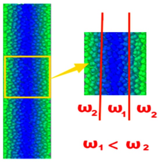
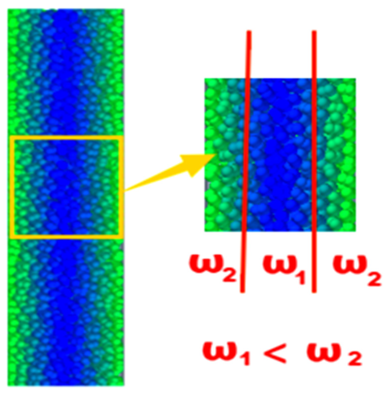
Rotational rolling disturbance: When particles are subjected to external tangential forces (such as friction generated by drill string rotation), if the resulting torque (Mf) exceeds the particle’s rolling resistance torque (Mr), the particle will undergo rolling motion about the contact point. During rolling, the azimuth (θ) of the particle’s long axis undergoes random changes, leading to a decline in bedding orientation parameters. As shown in Figure 4, the difference in particle angular velocity inside the drill rig increases the relative displacement between the central and edge particles inside the drill rig, and the stratification becomes worse.
Figure 4.
Diagram of internal angular velocity differences in drilling tools.
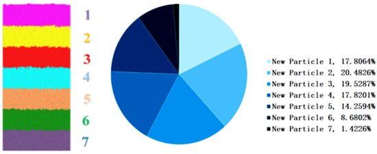
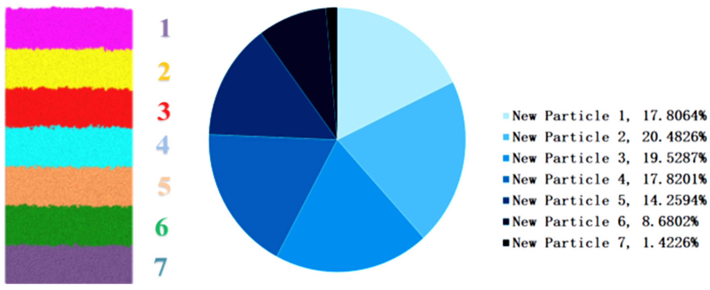
Shear-sliding disturbance: The interlayer angular velocity difference () is the core factor triggering shear sliding. When angular velocities differ between adjacent layers, shear stresses () develop between them, their magnitude being related to the angular velocity gradient z being the direction normal to the bedding plane). When the shear stress exceeds the static friction strength between particles, the particles slide along the bedding interface and the bedding between rock layers is destroyed. Figure 5 illustrates the particle stratification within rock layers and the proportional distribution of particle angular velocities across different rock strata.
Figure 5.
Particle stratification in rock layers and the proportional distribution of particle angular velocities across different rock layers.
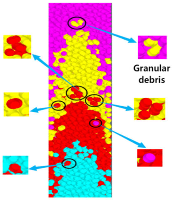
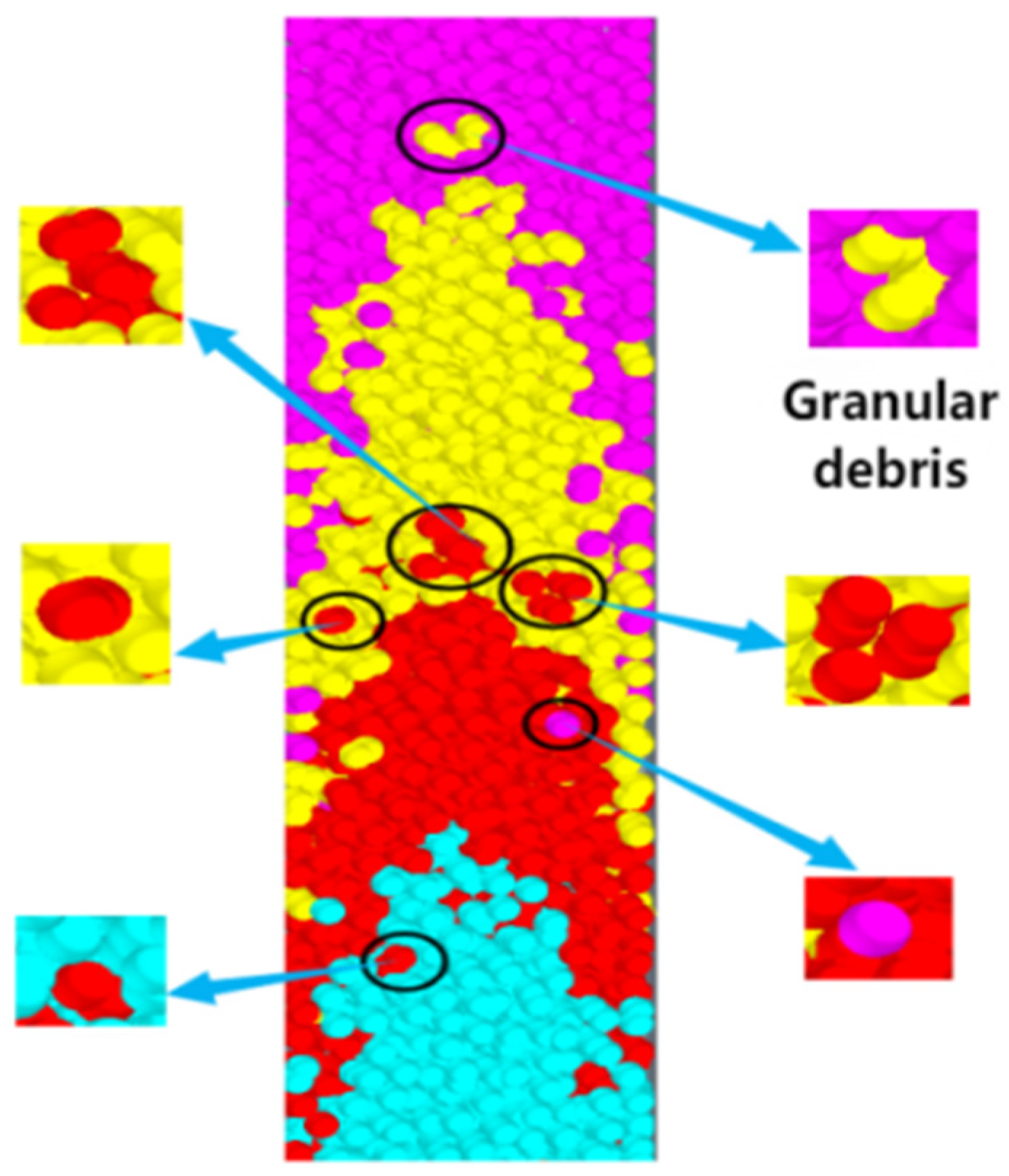
Collision-induced fracturing disturbance: During impact drilling or high-speed rotating shear, the kinetic energy of particle collisions increases, leading to elevated interparticle stress. When this stress exceeds the compressive strength of the particles, fragmentation occurs. This disturbance significantly alters the particle size distribution within the layer, increasing fine-grained particles that fill pores and reduce permeability. Concurrently, the bedding structure transforms from layered to debris-flow-like. As illustrated in Figure 6, collision-induced fragmentation occurs when angular velocity reaches a critical threshold, resulting in the emergence of particulate debris between distinct bedding planes.
Figure 6.
Collision-fractured particle debris.
2.3. Sequence Preservation Evaluation Method Based on Angular Velocity
To quantitatively assess the impact of drilling parameters on bedding preservation, this study proposes a sequence preservation evaluation method centred on particle angular velocity. Particle angular velocity not only directly drives the rotational motion about the particle’s axis but also serves as a pivotal transmission variable that links micro-scale disturbances to macro-scale bedding evolution. This occurs by altering the oriented arrangement of particle aggregates (disrupting the bedding’s primary orientation) and intensifying the tangential friction and shear forces between particles at bedding interfaces (fracturing cement bonds). This approach fills the gap in existing models between micro-and macro-scale processes. To achieve precise quantification, the framework innovatively constructs a dual-coupling model of ‘overall stratigraphic orientation evolution coupled with localised stratigraphic disruption’, overcoming the evaluation limitations of traditional models that ‘prioritize the whole over the parts’. Based on this, quantitative correlation equations linking particle angular velocity to dual-model metrics were established, leading to a comprehensive evaluation system: ‘angular velocity input–dual-model analysis–quantified stratification preservation output’. This systematically reveals the nonlinear influence of angular velocity on stratification preservation [36,37]. This framework enables the DEM model to transition from ’macroscopic phenomenon description’ to ‘microscopic mechanism-driven quantitative evaluation’, resolving the core challenges of ambiguous stratification evolution mechanisms and insufficient evaluation accuracy in traditional models.
- (1)
- Overall Bedding Orientation Evolution Model
- (a)
- Dynamical Equation Construction for Azimuthal Distribution
Laminar preservation can be evaluated by the degree of oriented arrangement of particle long-axis azimuths relative to the initial bedding plane. Within the angular velocity field, the evolution of particle azimuths () is governed by the combined effects of system rotation and random perturbations. The Fokker–Planck equation is a partial differential equation (PDE) describing stochastic processes. Based on statistical mechanics, the Fokker–Planck equation for the probability density function of azimuth distribution () is established [38]:
Oriented rotation term (−): This term characterises the systematic azimuth drift caused by angular velocity, where particles rotating around the normal to the bedding plane result in an orientation deviation.
Random diffusion term (): The diffusion coefficient reflects azimuthal randomisation caused by particle collisions, fluid drag, etc. In deep-sea sediments, correlates with particle size and pore fluid viscosity, and can be empirically calibrated as .
- (b)
- Analytical expression of the orientation index
The core of bedding preservation lies in the degree of ordered arrangement of particle long axes relative to the initial bedding plane (). If particle long axes are predominantly parallel to the bedding plane, the bedding structure remains distinct; if particles become randomly oriented due to disturbance, bedding orientation is lost. The bedding orientation index is the cosine mean of particle azimuths relative to the initial bedding plane [39]:
Assuming the initial azimuths follow a Gaussian distribution with mean 0 and variance :
Solving the Fokker–Planck equation via Fourier transform yields the orientation index at any time:
This formula indicates that the decay of comprises two components:
The angular velocity squared term (): This term reflects the coherence loss induced by directional rotation. It exhibits a negative exponential correlation with the square of angular velocity and the square of time, representing the severe disruptive effect of high-speed rotation on the directional orientation of bedding.
Diffusion term (): This term manifests the disordering caused by random perturbations. It exhibits a negative exponential correlation with the diffusion coefficient and time, representing the gradual impact of particle collisions on the preservation of bedding.
- (c)
- Quantitative Characterisation of Stratification Preservation
To intuitively describe the degree of lamination retention, the lamination retention index is defined. Where (initial ideal state), then:
When , , indicating that lamination retention is solely influenced by random perturbations, with a slow decay rate.
When , the term dominates the attenuation, indicating that high rotational speeds significantly reduce lamination retention.
- (2)
- Interbedding interface failure model
The interlayer interface failure model is central to elucidating the shear slip disturbance mechanism, wherein shear slip constitutes the predominant form of bedding failure during drilling operations. This process is intrinsically linked to the interlayer mechanical response triggered by non-uniform particle angular velocity distributions. The model focuses on two critical aspects: firstly, the dynamic mechanical properties of the cementation material at bedding interfaces, where shear strength is not constant but evolves dynamically with particle angular velocity—a fundamental prerequisite for accommodating the dynamic perturbations inherent in drilling operations; secondly, the coupling relationship between angular velocity gradients and interbed shear stresses, wherein the longitudinal angular velocity gradient generated by drill string rotation driving particle motion serves as the direct trigger for shear slip at bedding interfaces.
The strength of interbedding cementation is a key factor in resisting disturbance. Considering viscoelastic effects, the dynamic shear strength of cementation can be expressed as [40]:
where τ0 is the static cementation strength, and β is the angular velocity sensitivity coefficient.
The angular velocity gradient ∂ω/∂z arising from differing angular velocities between adjacent bedding planes induces interbedding shear stress :
where is the longitudinal variation in angular velocity, and η is the viscous coefficient of the particle group, which relates to particle density ρ, average particle diameter d, and motion velocity v.
When the shear stress τ exceeds the dynamic strength of the cement τd, failure occurs at the interlayer interface. The critical condition is:
Introducing the dimensionless perturbation parameter Dn to normalise the equation:
Criteria for stratum interface failure: Dn exhibits a positive correlation with . Greater longitudinal variation in leads to a higher stratum disturbance number Dn, indicating more pronounced stratum failure.
3. Discrete Element Analysis and Experimental Study
3.1. Experimental Methods and Platform
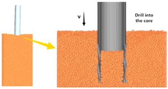
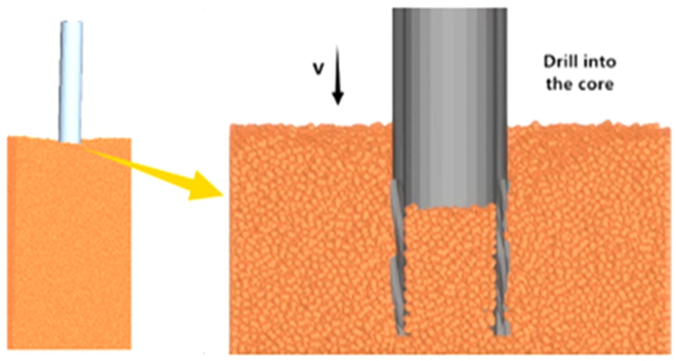
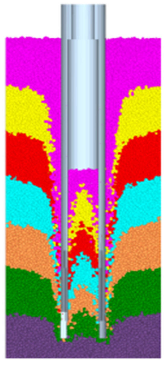
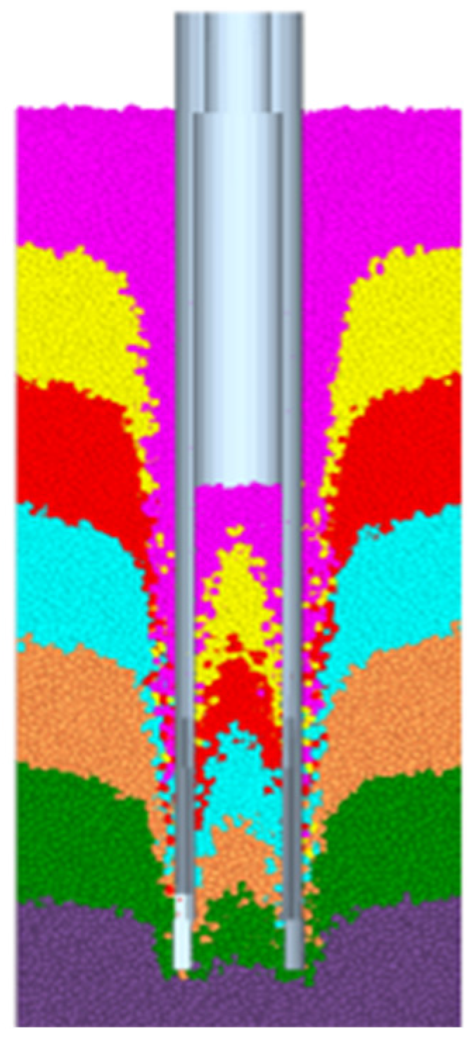
To directly observe the spatial distortion of stratigraphic structures during the drilling process, the core samples were longitudinally stratified prior to conducting Discrete Element Method (DEM) simulations. The intact core was equally divided along its longitudinal axis into seven independent cylindrical blocks. This stratification scheme, validated through preliminary simulations, effectively captures gradient variation characteristics from the interior to the periphery of the core while maintaining computational efficiency. Figure 7 illustrates the schematic diagram of the DEM sampling process. By establishing a stratified observation system, the deformation of rock strata in different radial positions can be tracked and analysed, which provides a basis for studying the influence law of multiple parameters of drilling tools on bedding preservation.
Figure 7.
Schematic diagram of the discrete element sampling process.
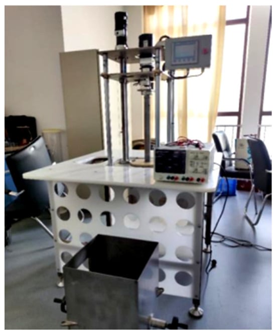
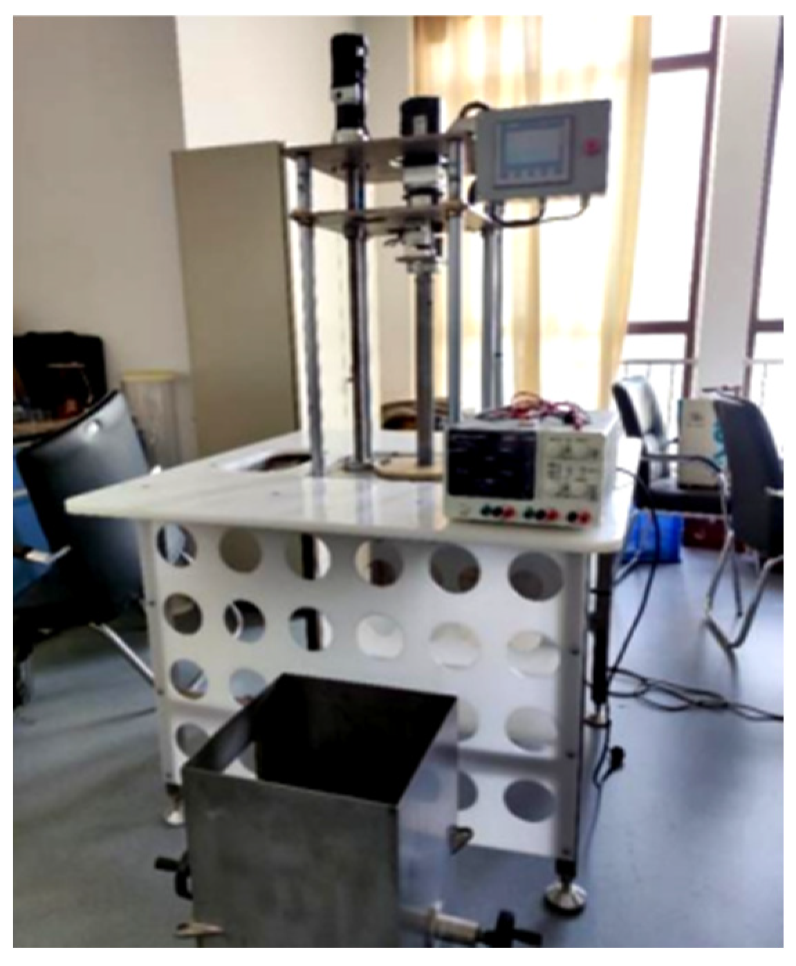
The multifunctional deep-sea drilling disturbance simulation test platform was constructed in the laboratory. The platform’s main frame is fabricated from high-strength alloy steel, exhibiting excellent dynamic stiffness to effectively suppress structural deformation under coupled high-speed rotation and high drilling pressure conditions. The drive system integrates a variable-frequency motor (0–400 rpm stepless speed regulation) with a servo electric cylinder feed mechanism, equipped with interchangeable core drilling tools ranging from a 40 to 60 mm internal diameter to accommodate diverse test parameters. The core measurement and control unit incorporates a non-contact laser tachometer, multi-axis force-torque sensors, and a dynamic data acquisition system. This enables synchronous monitoring and real-time recording of critical parameters including the rotational speed, feed rate, drilling pressure, and torque. The overall structure of the test platform is illustrated in Figure 8.
Figure 8.
Laboratory drilling rig test platform.
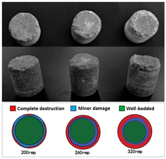
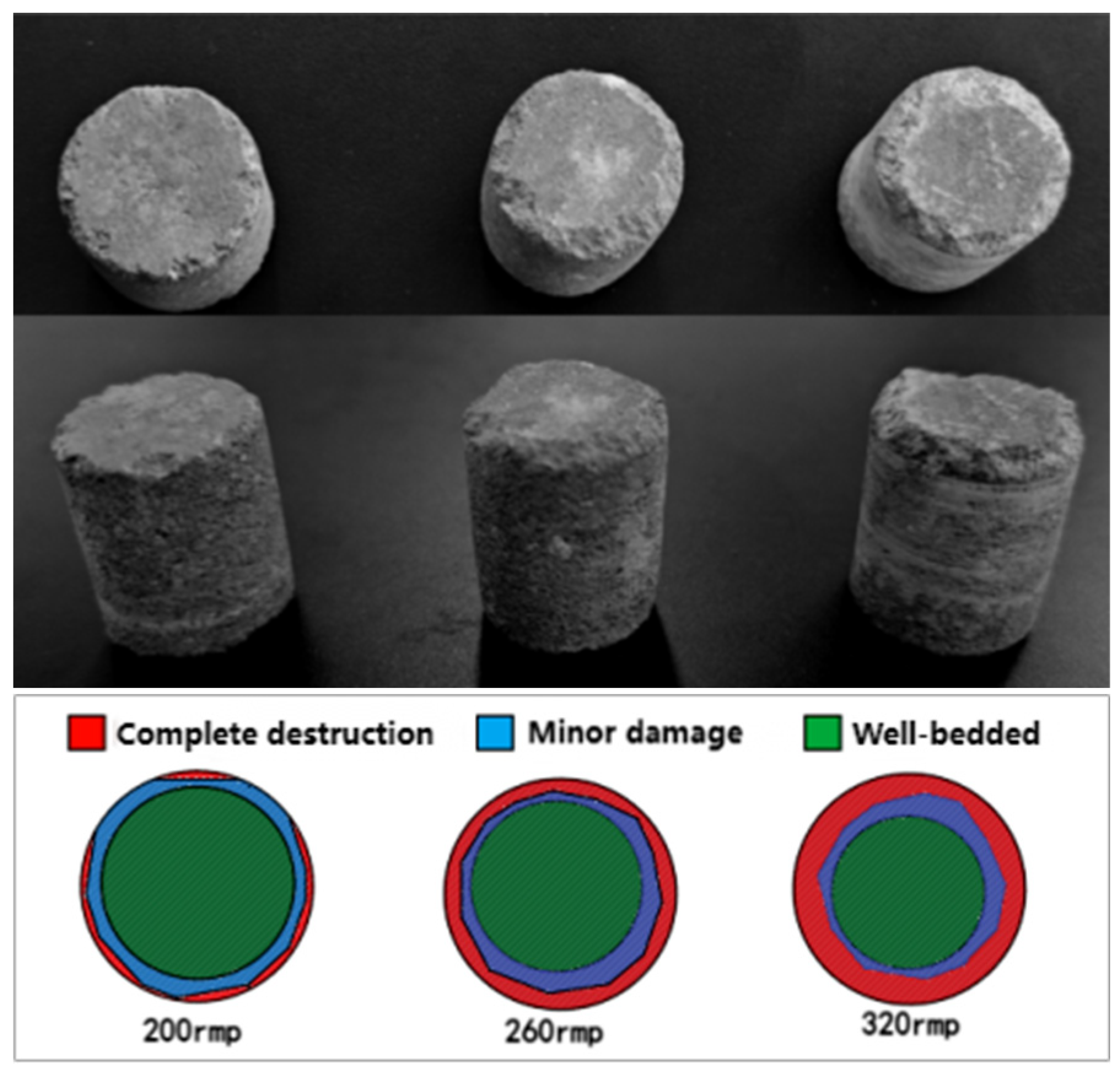
The test selected natural rock with well-developed and continuous bedding. In accordance with rock mechanics testing standards, it was cut into uniformly sized block specimens to ensure consistency in the mechanical properties of the test samples. Figure 9 illustrates the test samples and drilling test procedures. Prior to designing the test parameters, the operational parameter ranges of deep-sea drilling equipment (such as the Jiaolong submersible) were thoroughly referenced. Combined with preliminary pre-test results, the following three-factor parameter ranges were established: a rotational speed of 200–320 revolutions per minute, drill bit diameter of 40–60 mm, and feed rate of 0.018–0.054 m/s. Regarding the rotational speed, this range encompasses typical deep-sea sampling conditions from low disturbance (200 rpm) to routine operations (260 rpm) and high disturbance (320 rpm), enabling systematic investigation of the non-linear effects of rotational speed variation on particle angular velocity and stratification disruption. The 40–60 mm drill bit diameter aligns with mainstream specifications for deep-sea compact drilling systems while enabling analysis of how geometric parameters modulate bedding stress distribution and fidelity preservation by altering the cutting contact area. Feed rates of 0.018–0.054 m/s correspond to practical requirements ranging from low-speed precision sampling to high-efficiency operations, capturing the dynamic damage evolution patterns of core bedding under varying feed rates. Based on these ranges, the experiment employed a three-factor, three-level combination design. To minimise random error impacts, each parameter combination underwent three parallel trials. Microscopic damage characteristics (e.g., development of lamination surface fractures) were observed and recorded in real-time post-sampling. The specific experimental protocol is detailed in Table 2. Upon completion of the tests, the sample exhibiting the least core damage was selected. The annular surface region of the core was then subdivided into three zones: the completely damaged zone, the slightly damaged zone, and the well-preserved bedding zone. This approach enabled a direct, quantitative representation of stratigraphic preservation [41].
Figure 9.
Test samples and drilling test procedures.
Table 2.
Experimental design.
3.2. Analysis of Drill String Rotational Speed
In the discrete element numerical simulation, the drill string feed speed was fixed at 0.018 m/s with an inner diameter of 60 mm. Three rotational speeds were set: 200 rpm/min, 260 rpm/min, and 320 rpm/min. The rotational speed (, rpm) of the drill string and the angular velocity (, rad/s) of the particle trajectory at distance r from the axis satisfy a linear relationship:
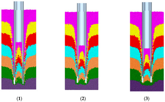
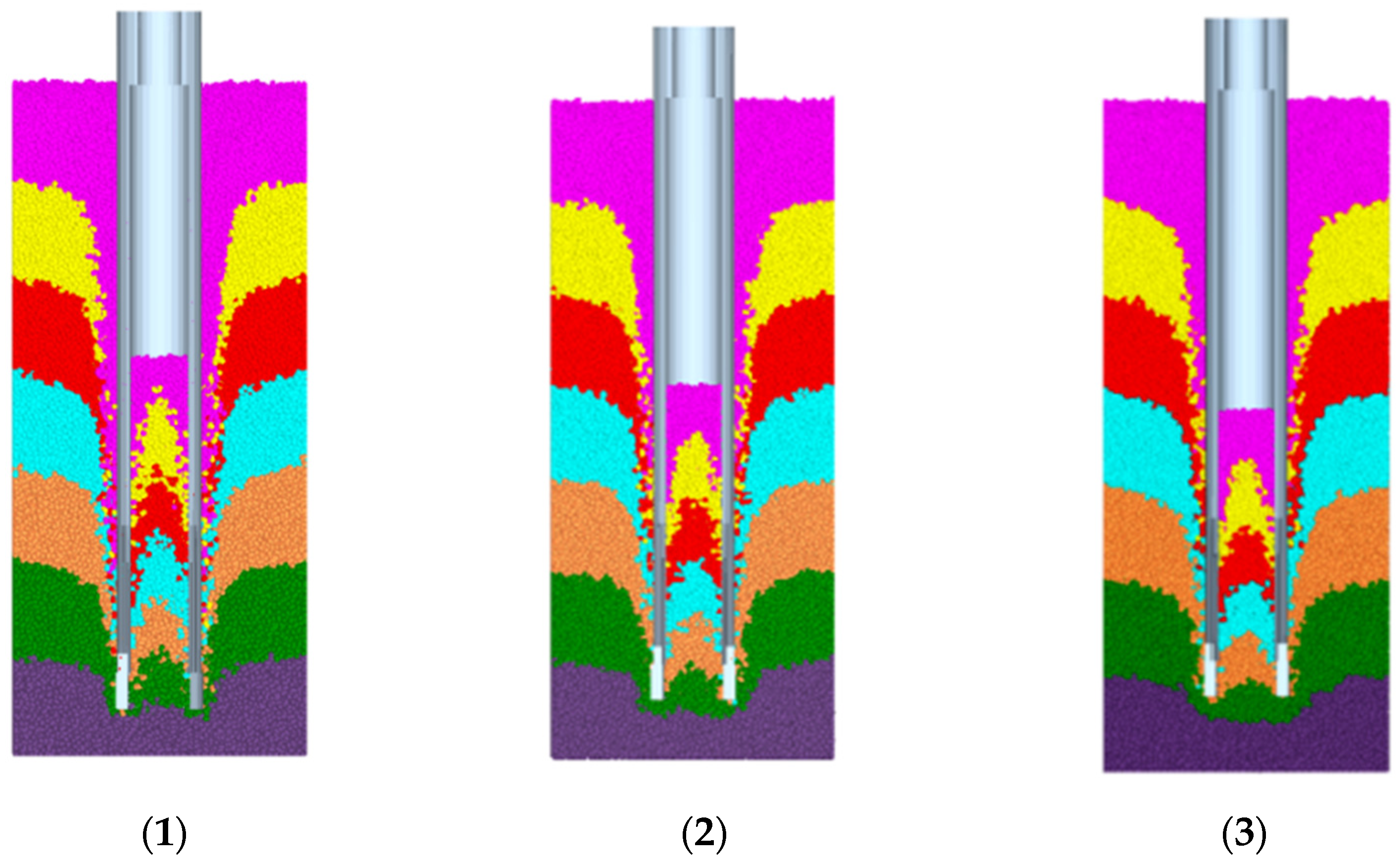
where is the drill bit radius. As the rotational speed increases from 200 rpm/min to 320 rpm/min, the angular velocity of particles at the drill edge rises from 20.94 rad/s to 33.51 rad/s. The particle kinetic energy () increases by a factor of 2.56, supplying energy for impact fragmentation. Figure 10 presents core sampling results at different rotational speeds.
Figure 10.
Core sampling results at different rotational speeds. (1) 200 rpm, (2) 260 rpm, (3) 320 rpm.
- (1)
- Analysis of overall stratigraphic sequence preservation
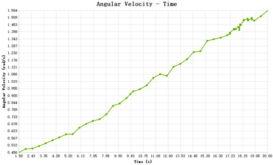
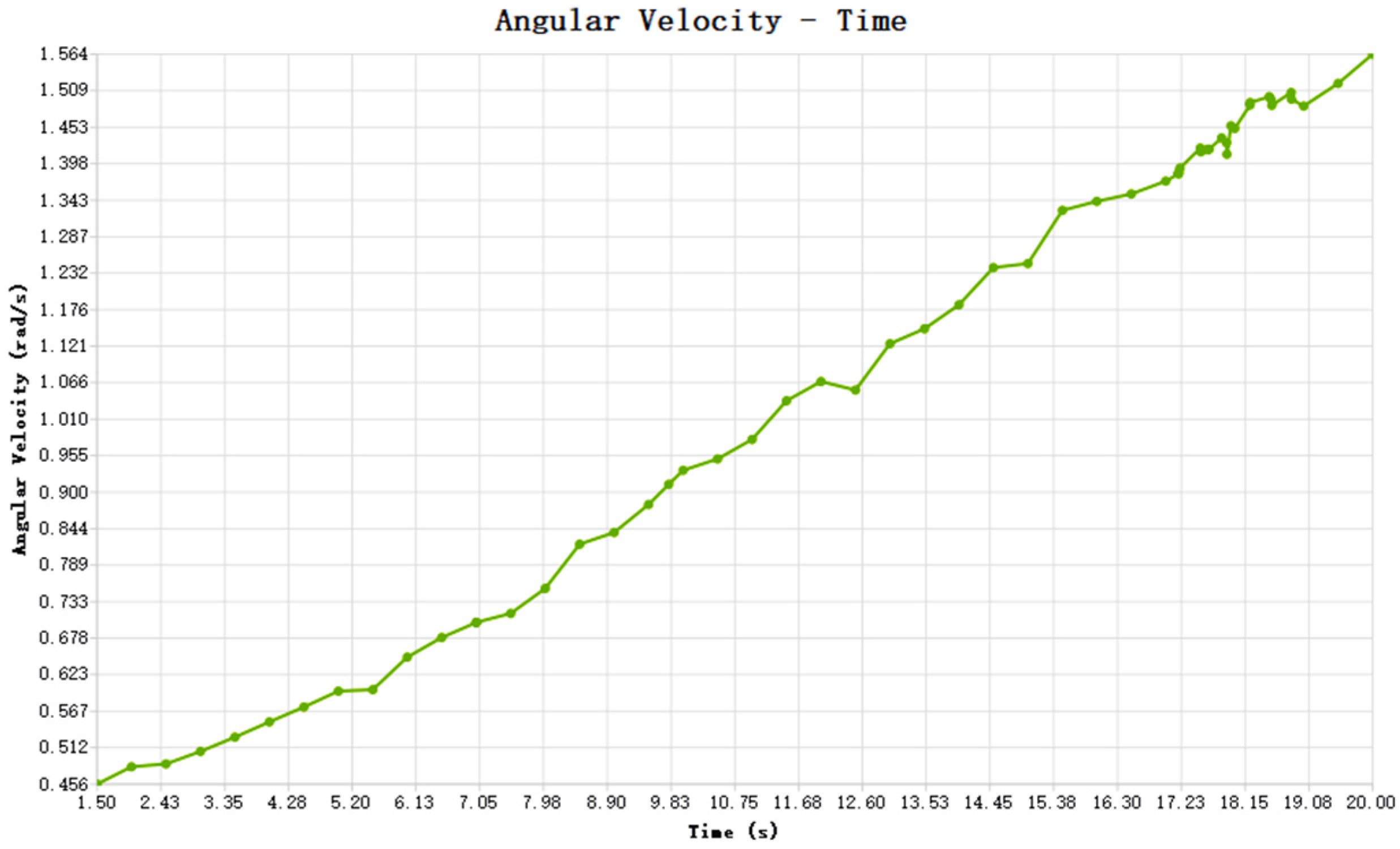
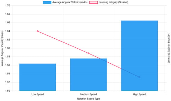
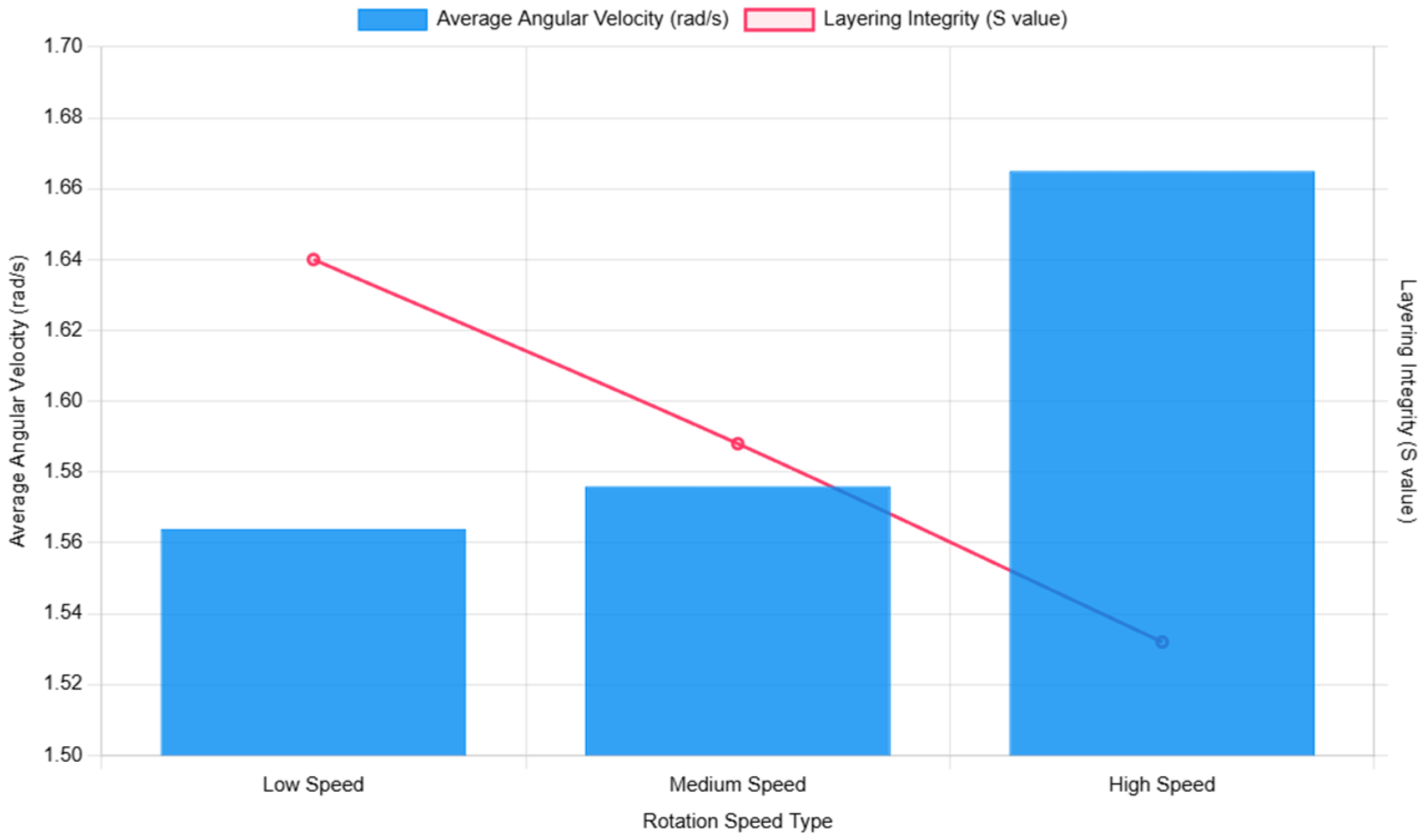
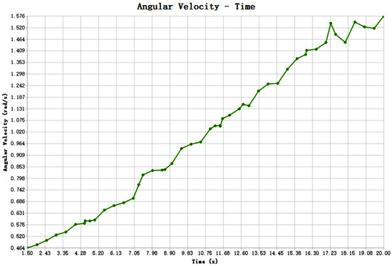
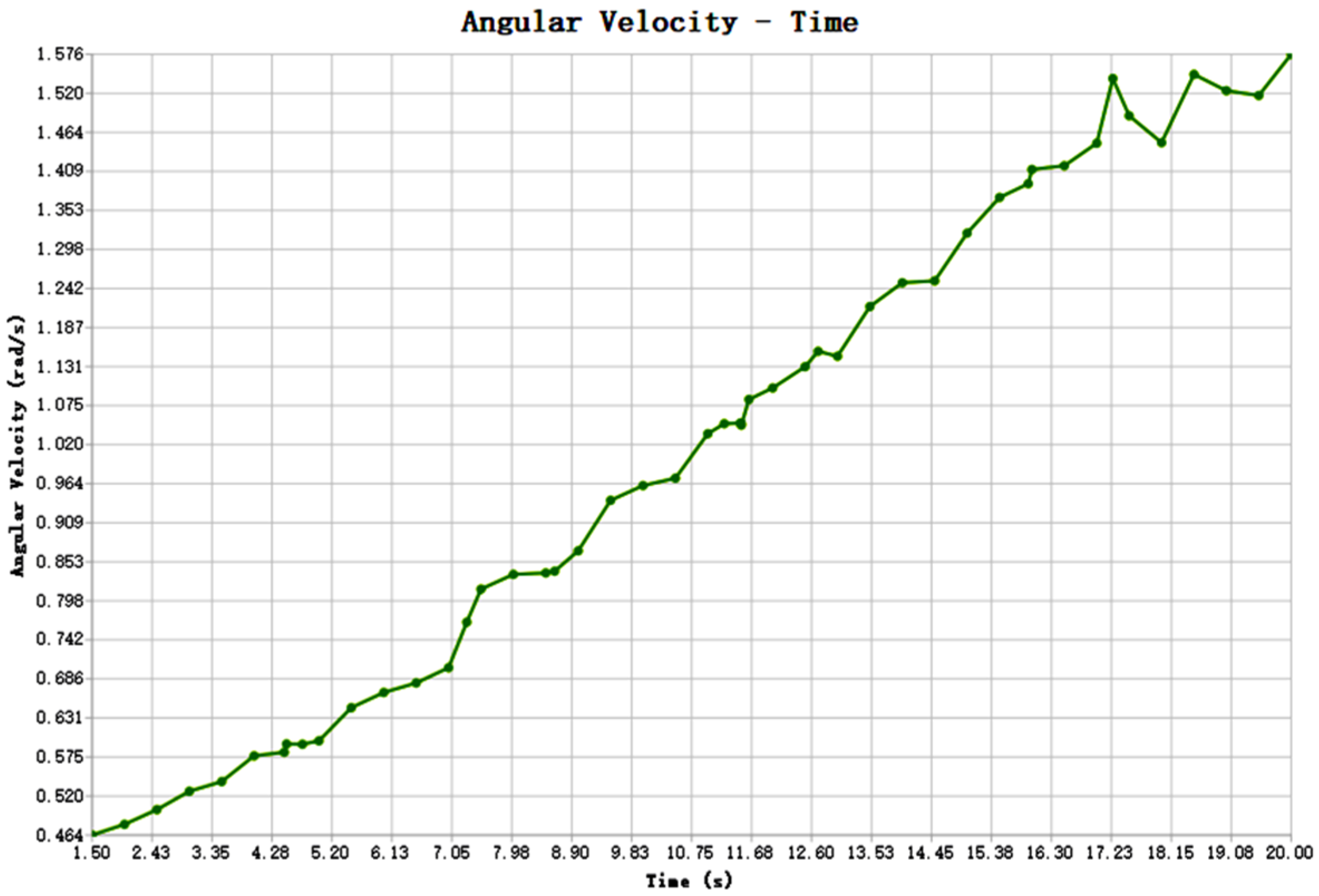
Figure 11 displays the particle angular velocity variation curve over time at low rotational speeds, from which the angular velocity curves at medium and high speeds can similarly be inferred. At different rotational speeds, particle angular velocity continuously increases with drilling duration until t = 20 s, where the average angular velocity is ωlow = 1.564 rad/s, ωmedium = 1.576 rad/s, ωhigh = 1.665 rad/s. Based on the directionality index model from Section 2, , the stratum retention index at different rotational speeds can be calculated as , with initial conditions and . At the simulated time , the following can be determined:. A smaller S value indicates poorer stratum retention, confirming that higher rotational speeds result in poorer stratum integrity. Figure 12 illustrates the average angular velocity and stratum retention index at different rotational speeds.
Figure 11.
Particle angular velocity versus time curve (low rotational speed).
Figure 12.
Schematic diagram of average angular velocity and lamination retention at different rotational speeds.
- (2)
- Analysis of inter-lamellar sequence retention
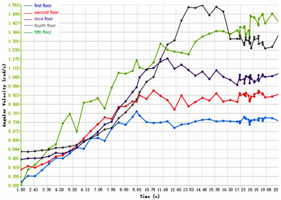
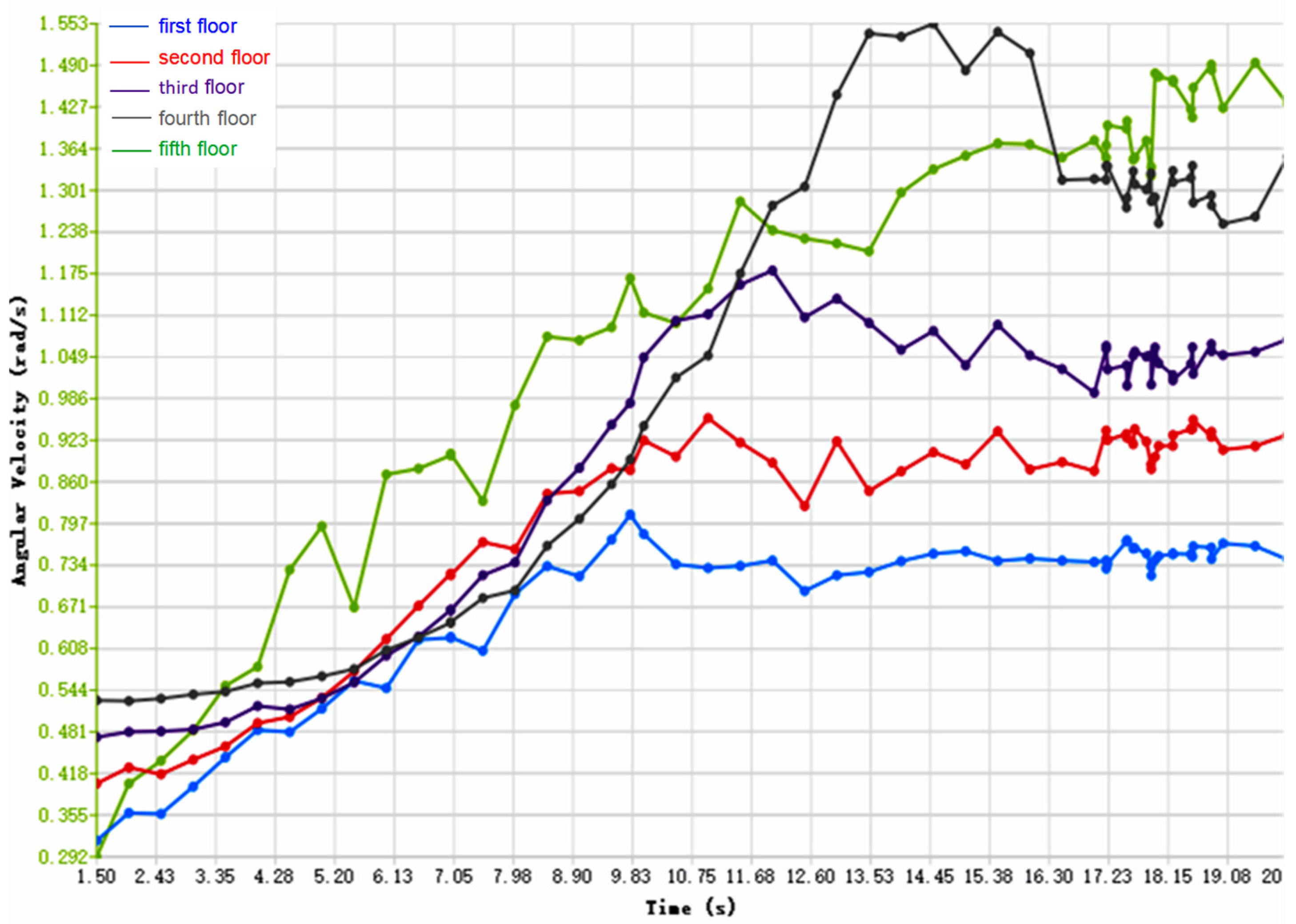
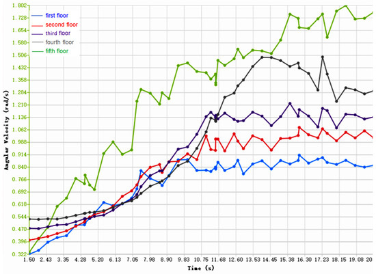
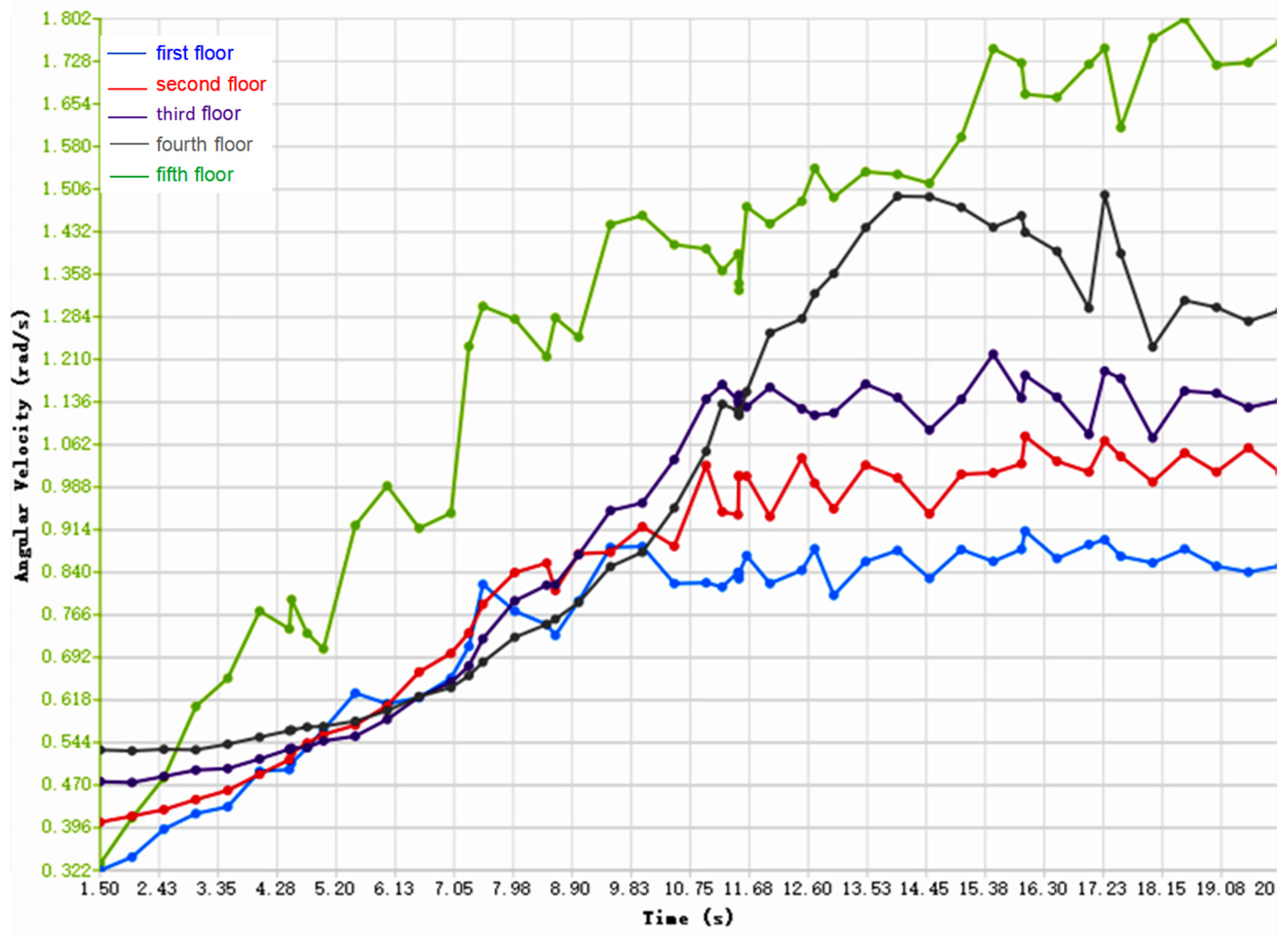
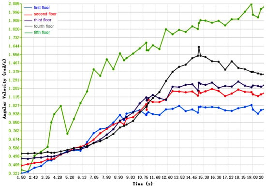
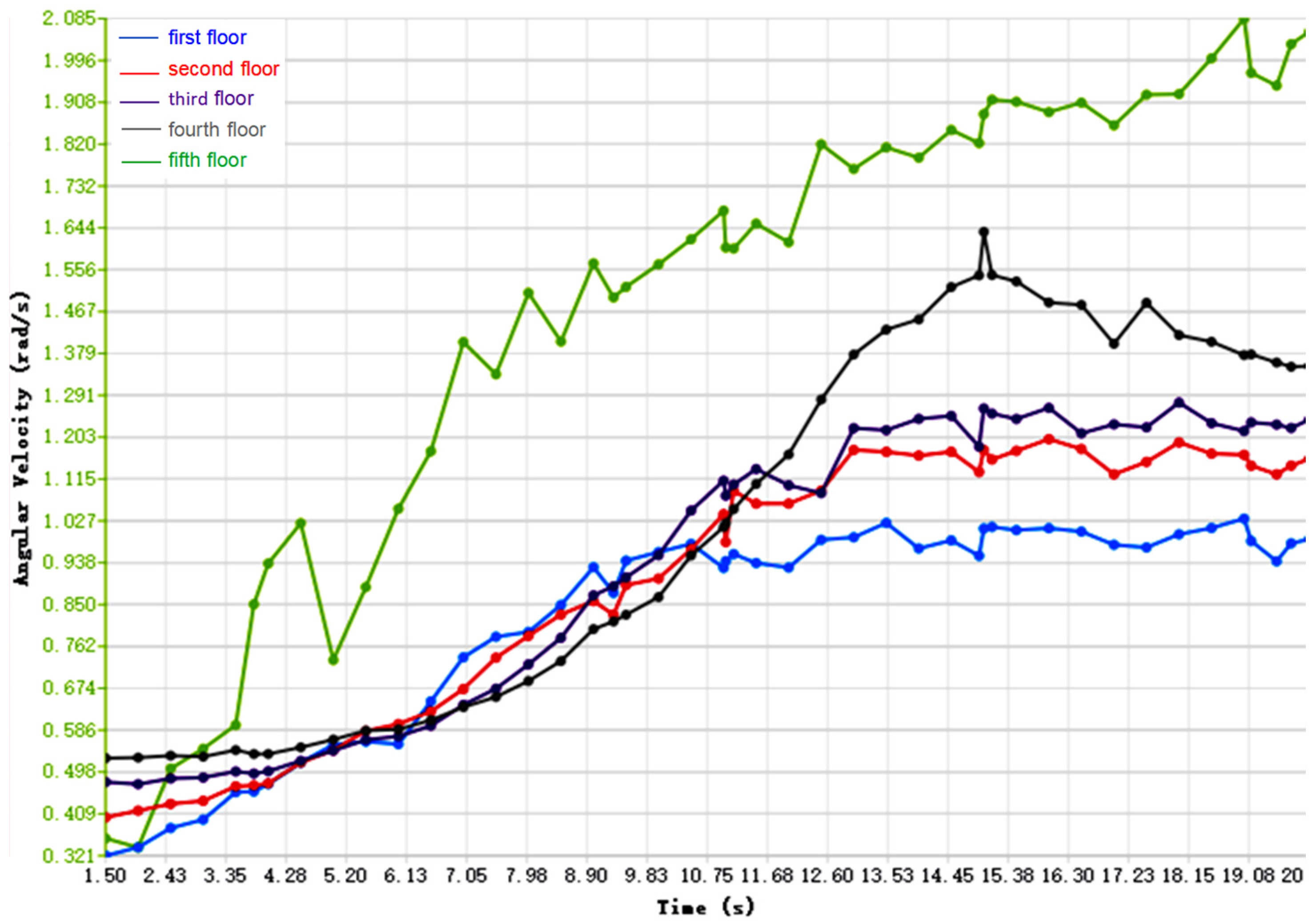
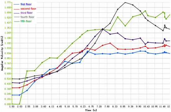
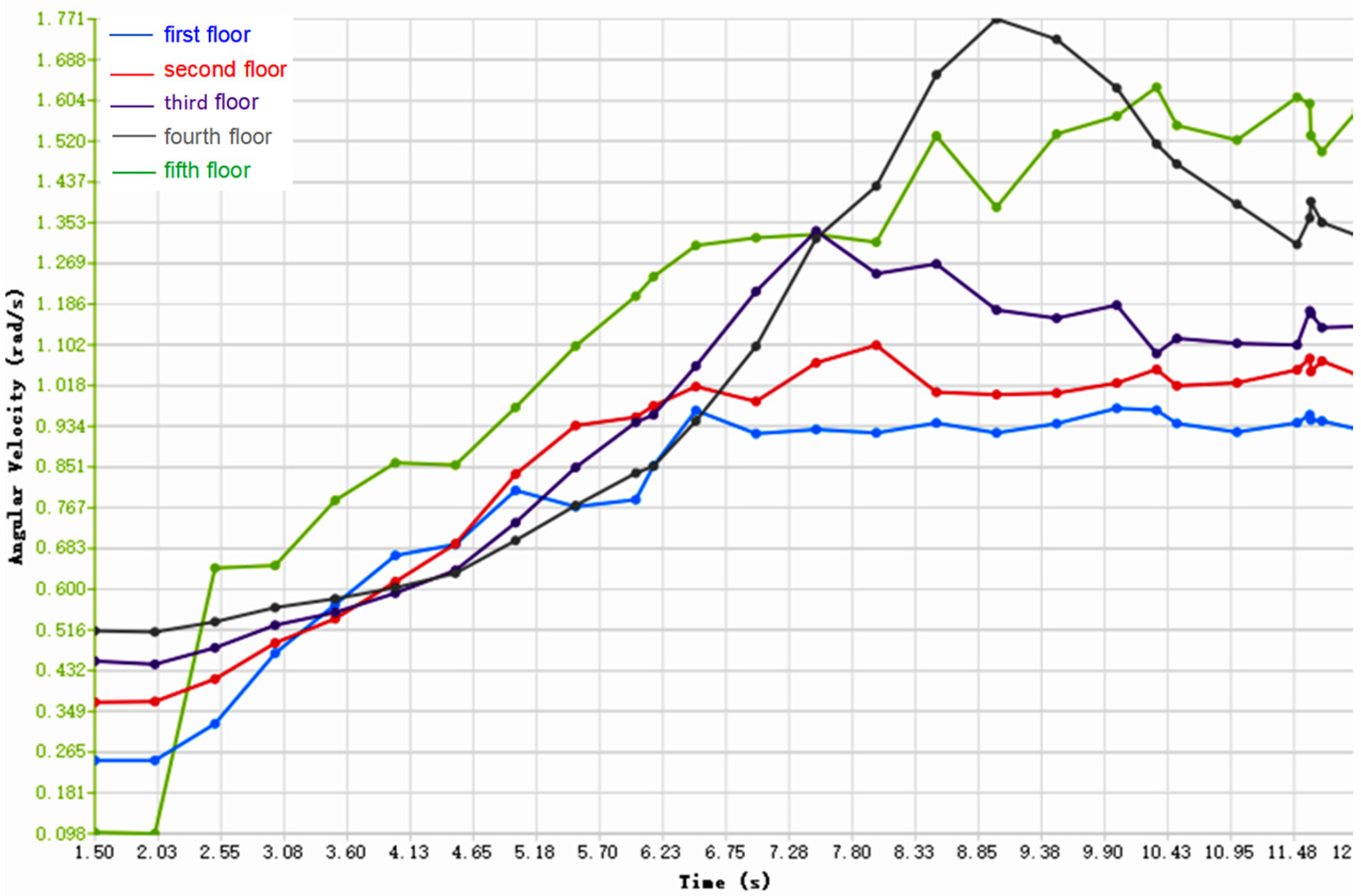
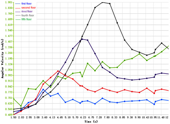
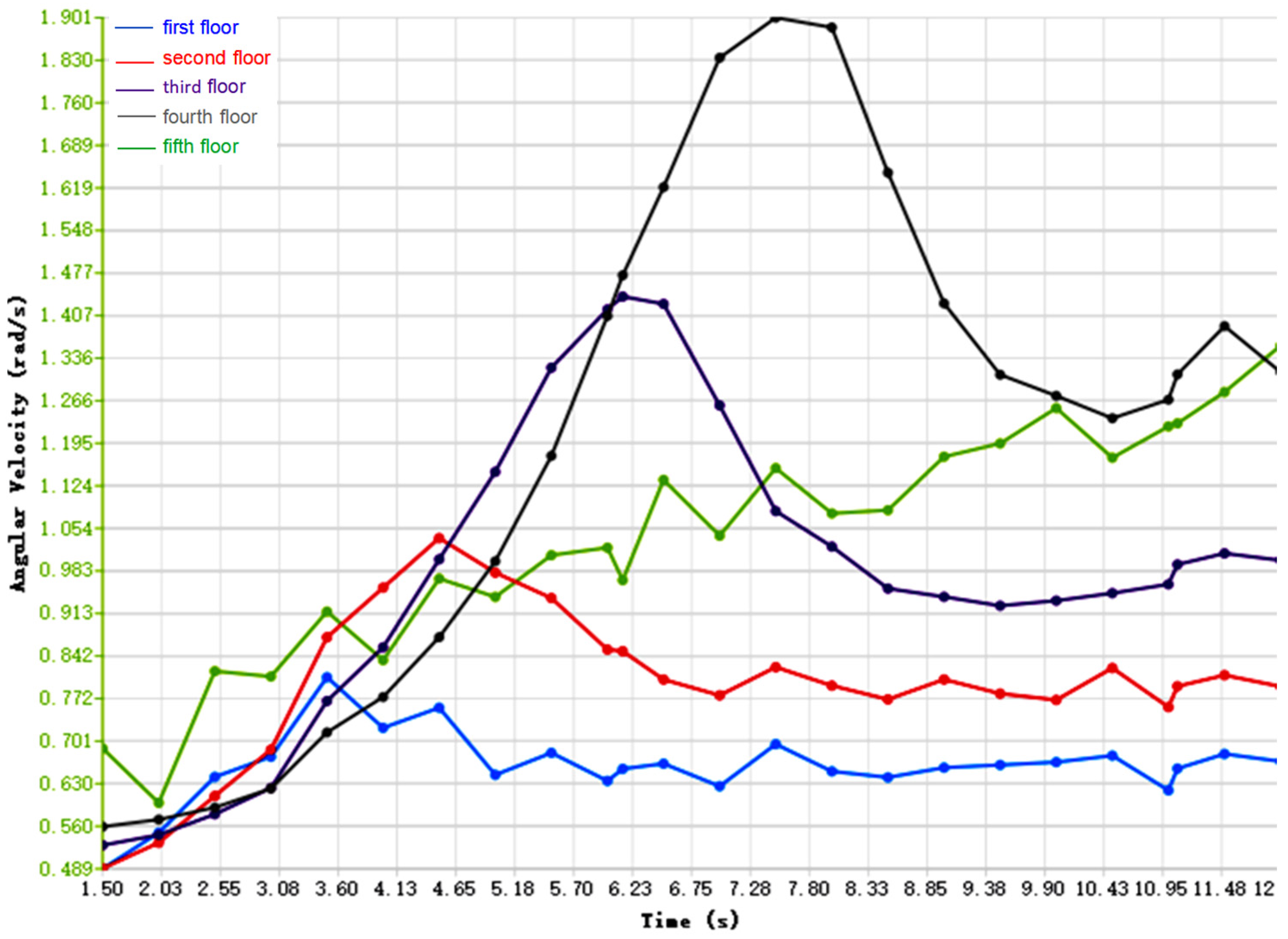
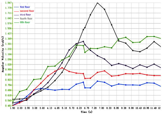
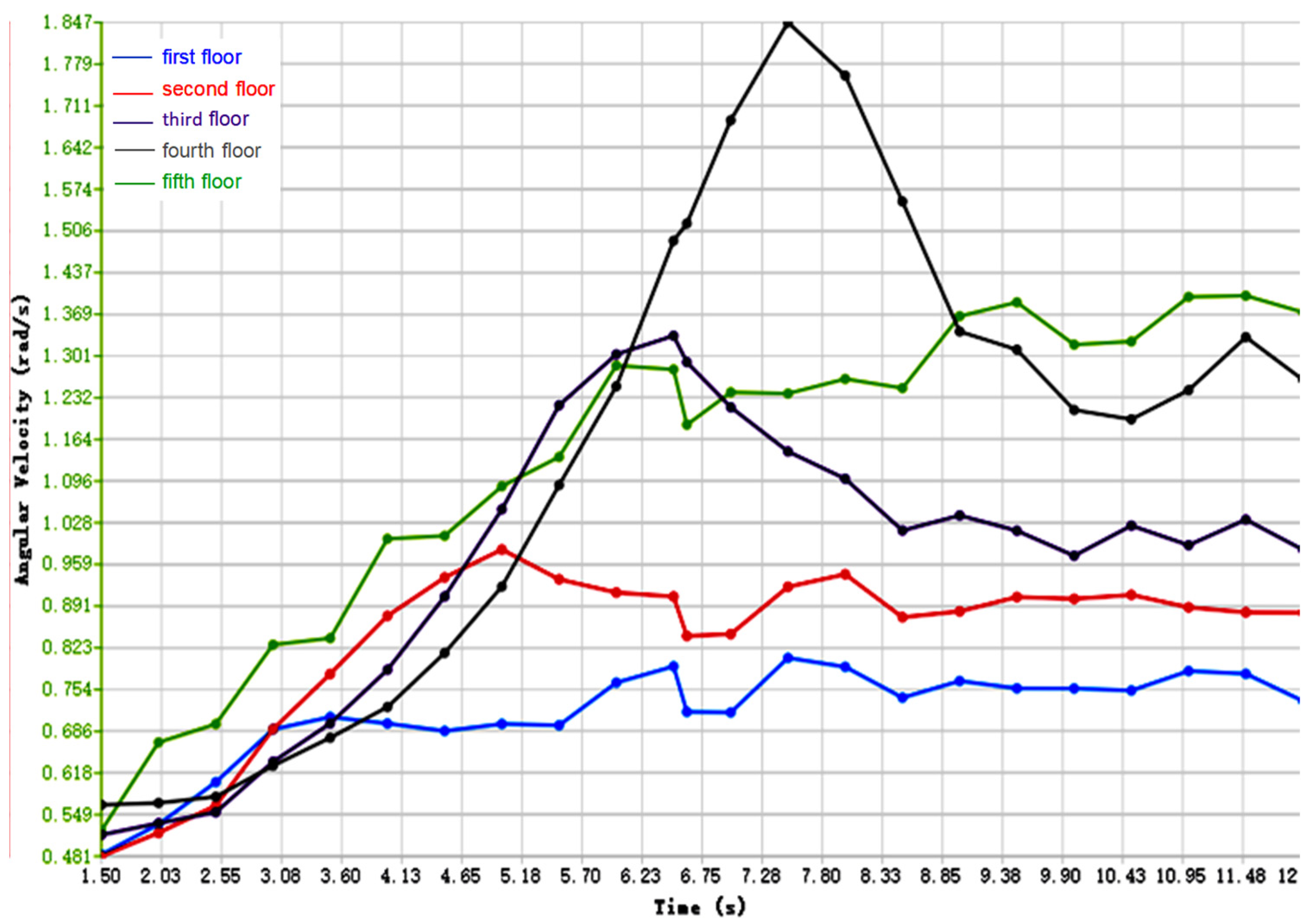
Figure 13, Figure 14 and Figure 15 illustrate the time-dependent variation curves of the average angular velocity for layers 1–5 of the particle at different rotational speeds. As indicated in Section 2 (), a greater angular velocity difference corresponds to a larger , resulting in more significant stratigraphic disruption between adjacent layers.
Figure 13.
Average angular velocity of layers 1–5 over time (low rotational speed).
Figure 14.
Average angular velocity of layers 1–5 over time (medium rotational speed).
Figure 15.
Average angular velocity of layers 1–5 over time (high rotational speed).
At different rotational speeds, the interlayer angular velocity difference exhibits a regular evolution pattern. The interlayer disruption quantification results presented in Table 3 indicate that as the rotational speed increases, the angular velocity difference in the surface layers (Layers 1–2) significantly increases (from 0.69 to 1.05), while the angular velocity difference in the deeper layers (Layers 3–4) gradually decreases (from 0.17 to 0.08). This discrepancy confirms that high rotational speeds primarily amplify shear slip within the drill bit’s direct action zone (surface layers), thereby intensifying surface layer destruction, while relatively diminishing disturbance to deeper layers.
Table 3.
Quantification of interlayer damage at different rotational speeds.
- (3)
- Experimental study at different rotational speeds
Figure 16 presents a comparison of the core surface morphology at different rotational speeds. At 200 rpm, the sample surface exhibited only sparse micro-fractures, with continuous and distinct bedding planes. Increasing the speed to 260 rpm resulted in a marked increase in fracture density, accompanied by thin-layer detachment in localised areas. When the rotational speed was further increased to 320 rpm, extensive flaking occurred on the core’s bedding surface, resulting in a sharp decline in the integrity of the bedding structure. The experimental results confirm that low rotational speeds can significantly suppress the cumulative effect of particle kinetic energy during sampling, serving as an effective means to reduce bedding disturbance and protect the bedding structure. Under the parameter combinations employed in this study, 200 rpm was identified as the optimal rotational speed parameter.
Figure 16.
Sampled cores at different rotational speeds.
The influence of the drill speed on stratigraphic preservation was revealed by discrete element simulation and experimental analysis. Increasing the speed from 200 rpm to 320 rpm elevated particle kinetic energy, resulting in reduced lamination preservation (S value) and diminished fidelity. Inter-lamination analysis revealed that high speeds intensified shear slippage in surface layers (1–2 layers), with minimal impact on deeper strata. Experiments demonstrated that core bedding remained intact at low rotational speeds (200 rpm), whereas extensive flaking occurred at high speeds. Consequently, employing a lower rotational speed (200 rpm) effectively suppresses disturbance and optimises bedding preservation.
3.3. Analysis of Feed Speed
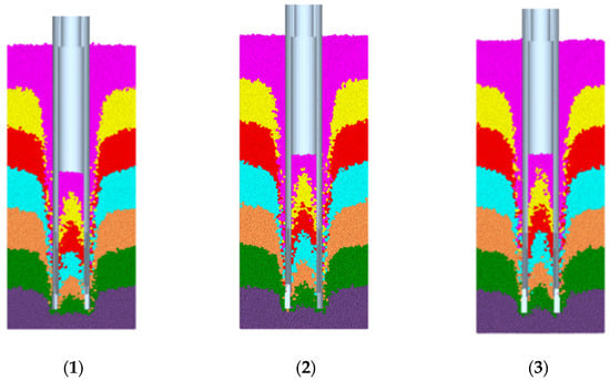
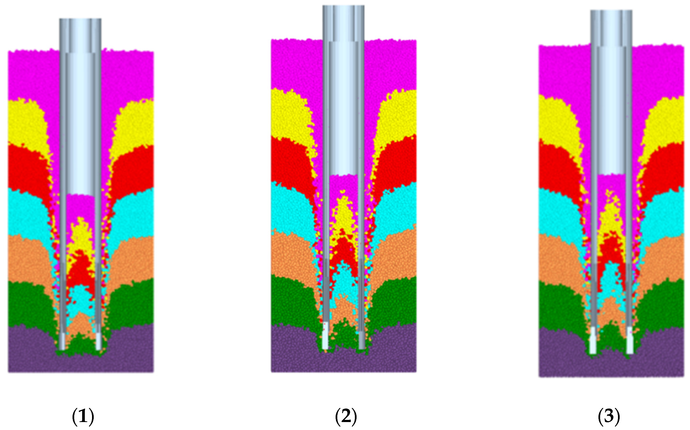
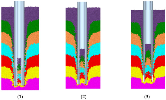
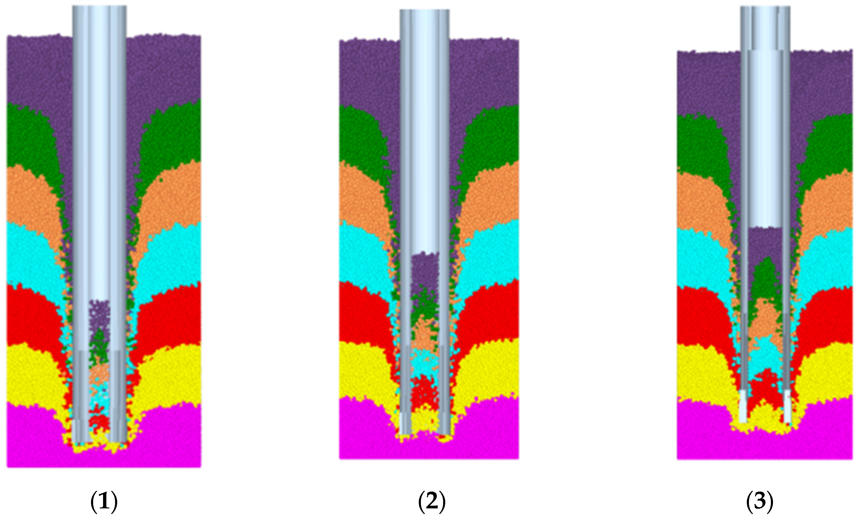
In the discrete element simulation, the drill bit rotational speed was fixed at 260 rpm with an inner diameter of 60 mm. Three feed speeds were sequentially set for simulation: 0.018 m/s, 0.036 m/s, and 0.054 m/s. The feed speed alters the normal stress between particles () via axial pressure (), where F is axial load and is the drill bit cross-sectional area. This subsequently influences the shear slip critical condition (). When increases from 0.018 m/s to 0.054 m/s, rises, causing the sliding friction strength () to triple and suppressing shear slip disturbance at low rotational speeds. However, an elevated feed speed intensifies particle–drill inner wall friction, increasing the tangential force (). At , this paradoxically induces greater sliding. Furthermore, the feed rate dictates particle residence time within the core barrel (, where is core length), influencing the time-integrated effect of angular velocity. Figure 17 illustrates core sampling results at varying drilling speeds.
Figure 17.
Core sampling results at different drilling speeds. (1) 0.018 m/s, (2) 0.036 m/s, (3) 0.054 m/s.
- (1)
- Analysis of overall stratigraphic sequence preservation
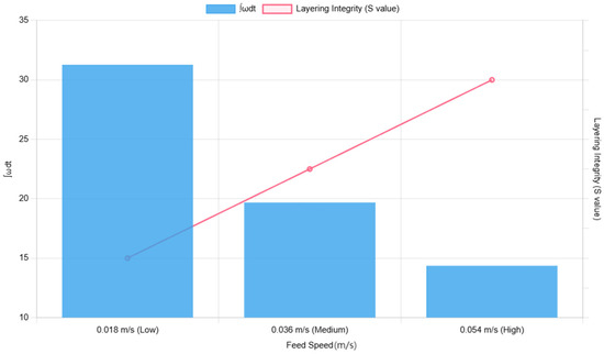
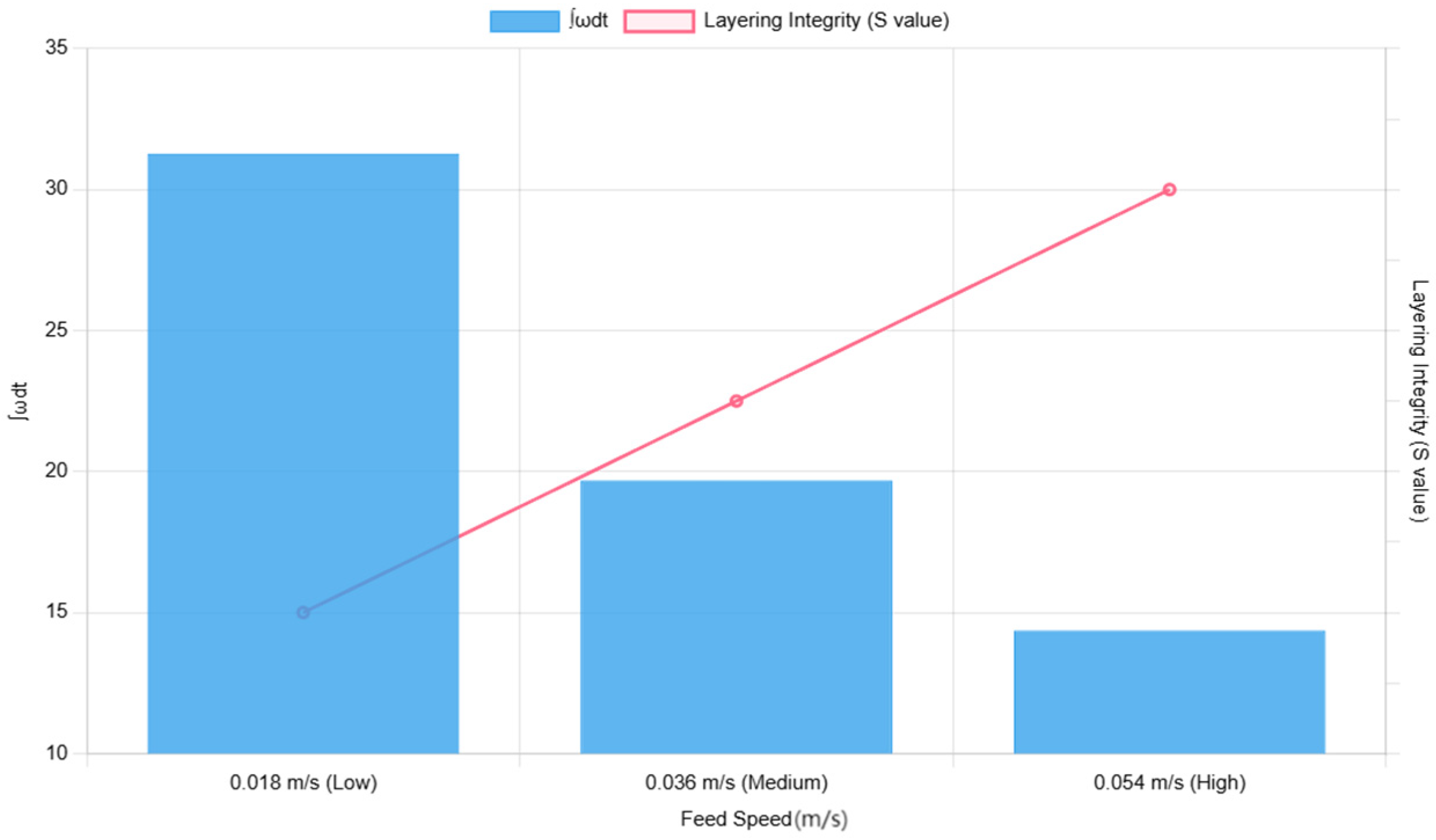
Figure 18 illustrates the temporal variation in particle angular velocity at low feed speeds; analogous curves for medium-to-high feed speeds can similarly be derived. Across varying feed speeds, particle angular velocity progressively increases with drilling duration, though particle residence times differ: , , . According to the directionality index model in Section 2 (), a higher value of corresponds to a lower value of , indicating poorer stratigraphic integrity (S). Thus, implies that a smaller S value signifies poorer stratigraphic integrity. Consequently, higher drilling speeds yield better stratigraphic integrity, though excessively high speeds may cause particle collisions and disturbances that disrupt stratigraphic integrity. Figure 19 illustrates the stratigraphic integrity retention at different feed rates.
Figure 18.
Curve of particle angular velocity versus time (low feed speed).
Figure 19.
Schematic diagram of average angular velocity and stratigraphic preservation under different feed rates.
- (2)
- Analysis of bedding preservation between interbedding sequences
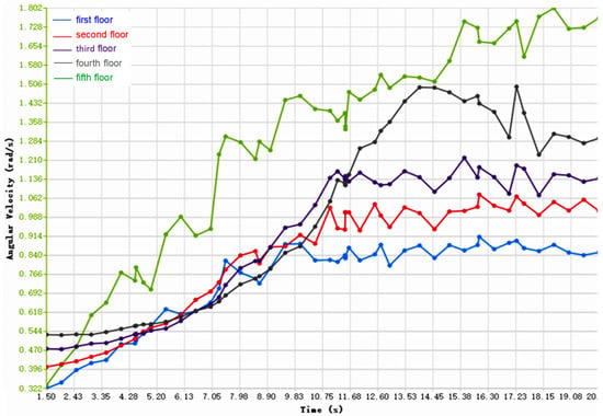
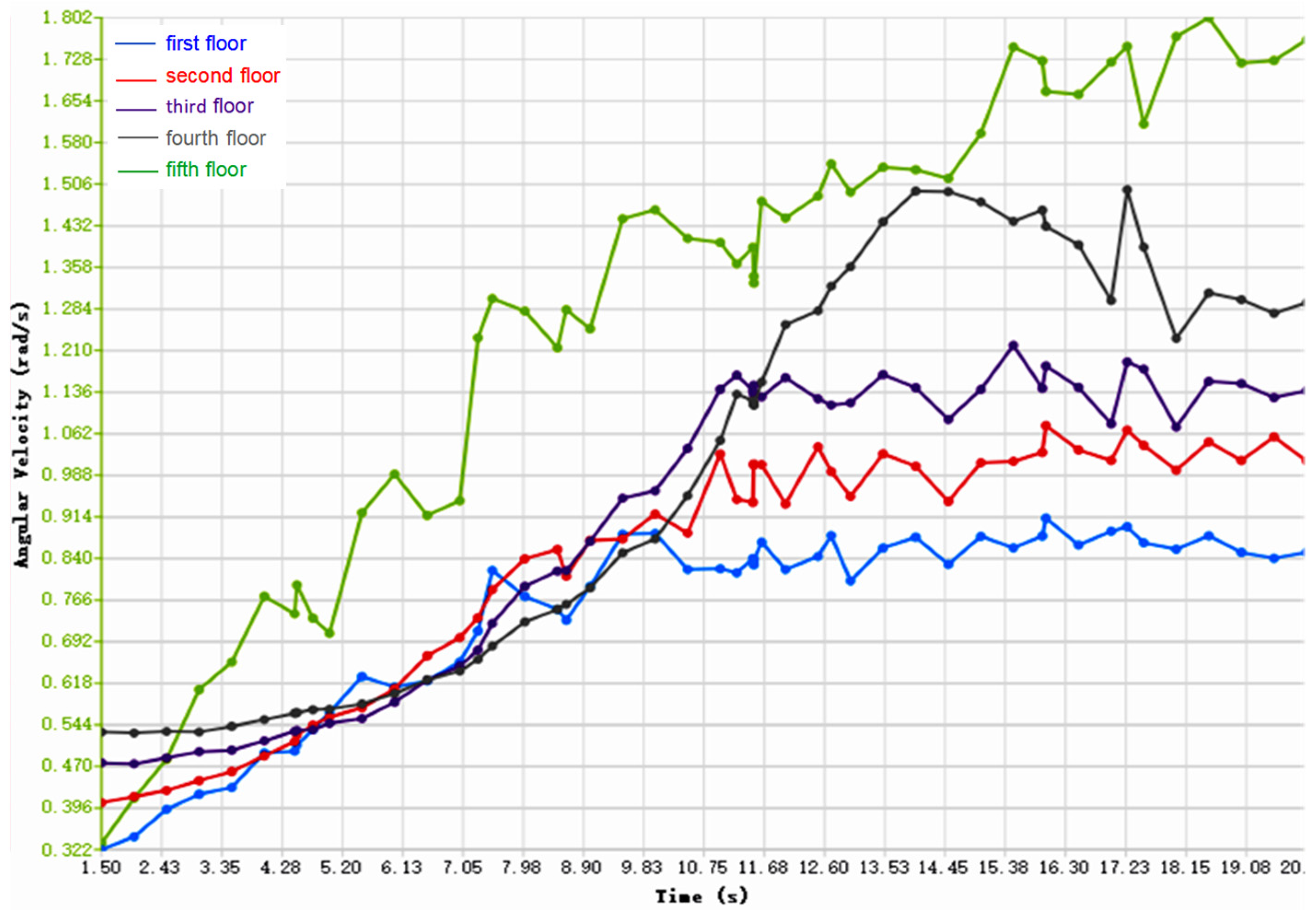
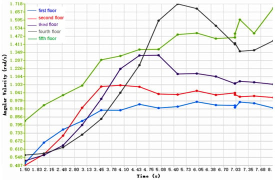
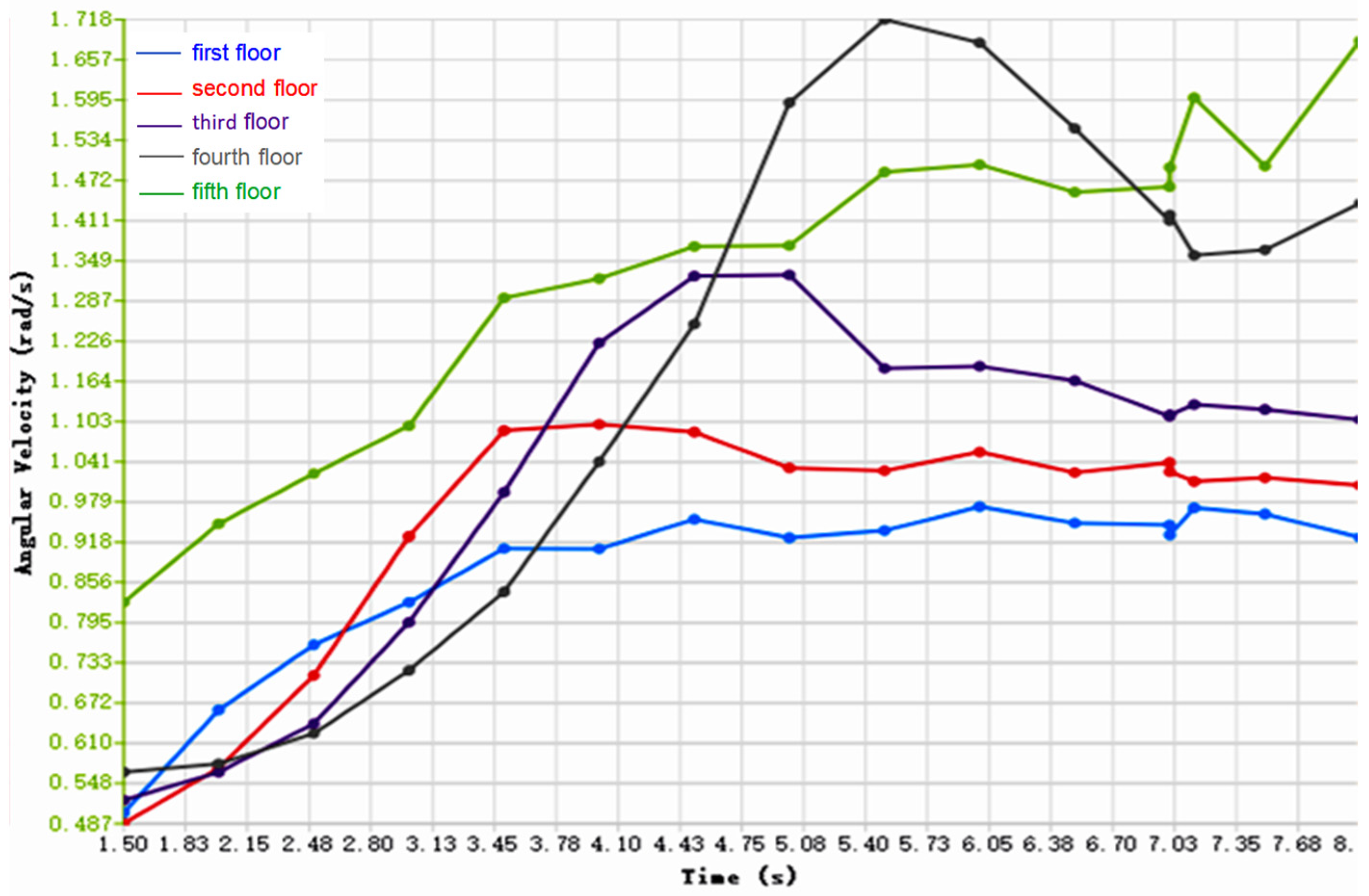
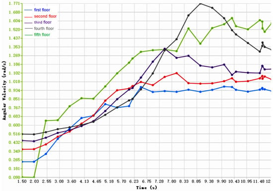
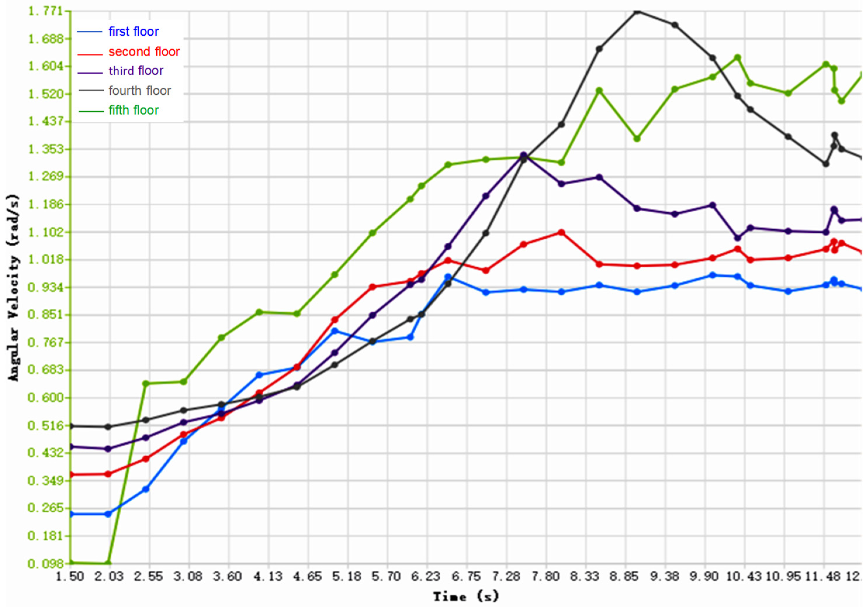
Figure 20, Figure 21 and Figure 22 depict the average angular velocity versus time curves for layers 1–5 of the core sample. Given that particle residence times within the core barrel vary with the feed speed, a holistic qualitative stratigraphic evolution model was employed to analyse each stratigraphic sequence. As shown in the figure, the angular velocity integral of each layer under different drilling speeds follows the pattern ∫ω2dt < ∫ω3dt < ∫ω4dt < ∫ω5dt < ∫ω1dt. According to the directional index model , a larger ∫ωdt value results in a smaller Dt value, and a smaller bedding retention index S value indicates poorer bedding retention. It can be concluded that the bedding retention is better in layers 2, 3, and 4, while it is poorer in layers 1 and 5. This demonstrates that the feed rate primarily affects the degree of bedding damage rather than the preferential tendency of damage occurrence.
Figure 20.
Average angular velocity of particles in layers 1–5 versus time (low feed speed).
Figure 21.
Average angular velocity of layers 1–5 over time (medium feed speed).
Figure 22.
Average angular velocity of layers 1–5 over time (high feed speed).
- (3)
- Experimental study at different rotational speeds
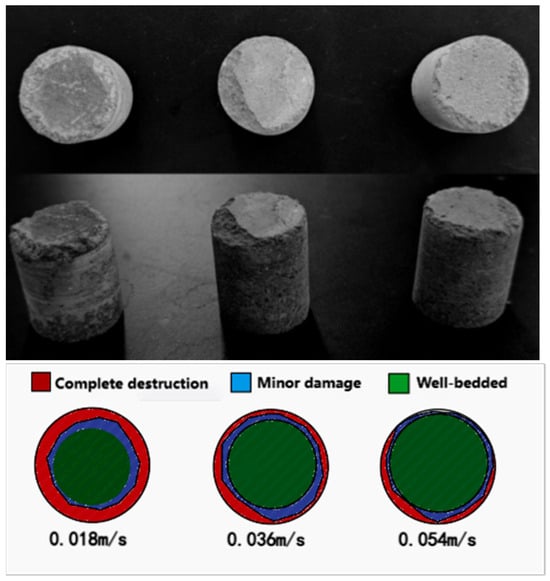
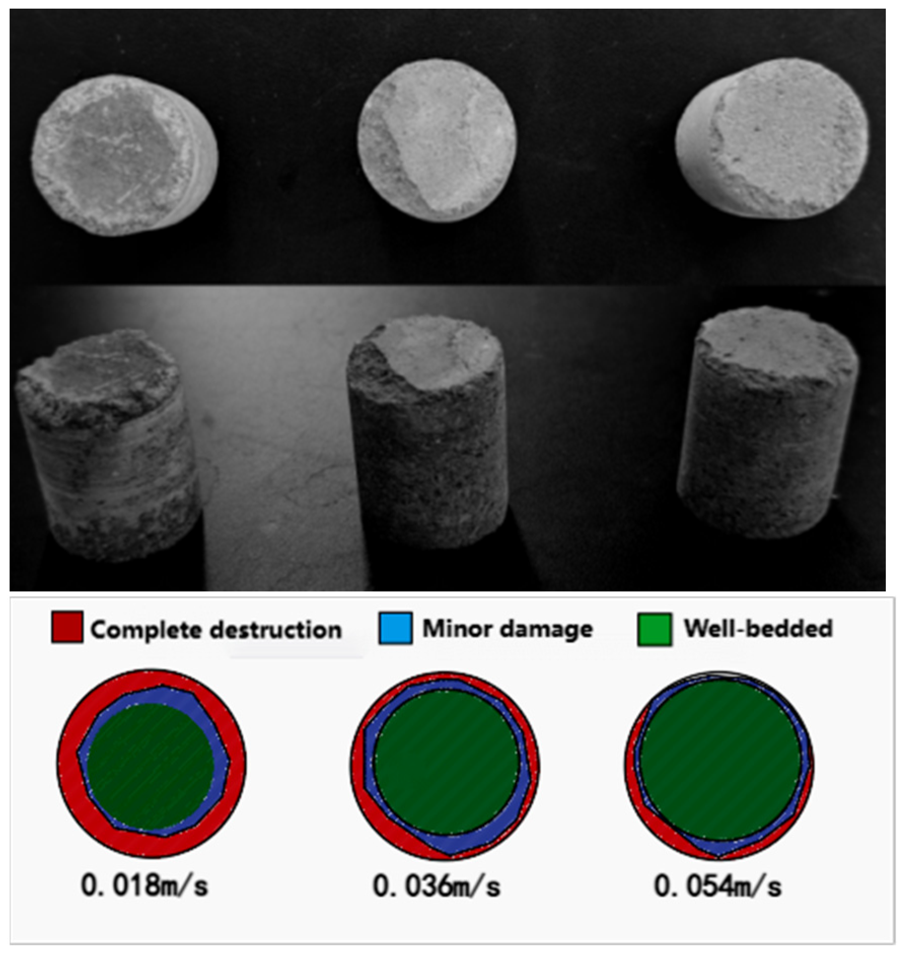
The surface morphology of cores sampled at different penetration rates is compared in Figure 23. At 0.054 m/s, the surface was nearly free of visible cracks with continuous bedding. A reduction to 0.036 m/s notably increased micro-crack density, with the damaged zone extending about 2 mm. Further reduction to 0.018 m/s, which prolonged particle residence time in the barrel, generated multiple through-going cracks in the bedding, exceeding 5 mm in depth. This trend demonstrates that an increased penetration rate effectively inhibits bedding disturbance by shortening the particle–bedding interaction time. Consequently, among the parameters tested, 0.054 m/s is determined to be optimal.
Figure 23.
Sampled cores at different drilling speeds.
The influence of the feed rate on texture preservation was revealed by discrete element simulation and testing. The feed speed jointly affects bedding fidelity through axial pressure and particle residence time. Results indicate that increasing the speed from 0.018 m/s to 0.054 m/s shortens particle residence time, enhances the bedding preservation index S, and improves structural integrity. Interlayer analysis indicates that layering retention is optimal in layers 2–4 under medium-to-high feed rates. Testing confirms that core surfaces remain largely intact at 0.054 m/s, whereas through-cracks appear at 0.018 m/s. In summary, increasing the feed rate effectively suppresses disturbance, with 0.054 m/s identified as the optimal parameter.
3.4. Analysis of Drill String Bore Diameter
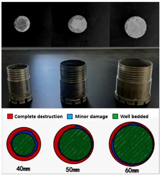
This study examines the effect of the tool inner diameter (40 mm, 50 mm, 60 mm) on core disturbance via discrete element simulations, under a fixed rotation speed of 260 rpm and a feed speed of 0.036 m/s. The aim is to elucidate the intrinsic connection between particle kinematics and bedding damage governed by spatial confinement. By modifying the radial space for particle movement, the inner diameter reconfigures the angular velocity distribution and consequently, the disturbance mechanism. The corresponding core sampling results are presented in Figure 24.
Figure 24.
Core sampling results under different drill tool inner diameters. (1) 40 mm, (2) 50 mm, (3) 60 mm.
- (1)
- Analysis of overall stratigraphic sequence preservation
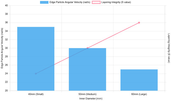
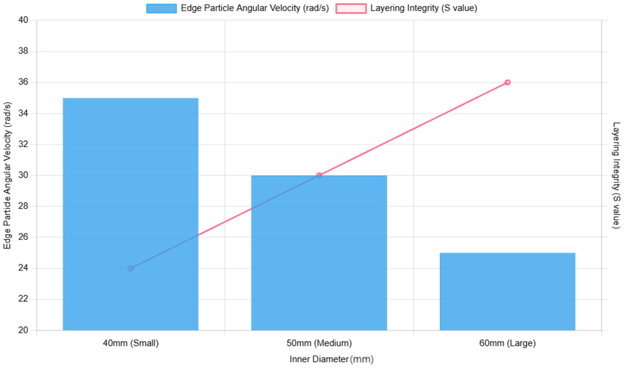
Across varying inner diameters, the radial angular velocity distribution satisfies , where R is the drill bit radius. Smaller inner diameters yield higher angular velocities for peripheral particles. At a 40 mm inner diameter, peripheral particles exhibit a 35 rad/s angular velocity; this decreases to 25 rad/s at a 60 mm inner diameter. According to the orientation index model from Section 2, under different drill bit inner diameters, . A smaller S value indicates poorer stratification retention. Hence, larger drill bit inner diameters yield better stratification. Figure 25 illustrates the schematic diagram of average angular velocity and bedding retention under different inner diameters.
Figure 25.
Schematic diagram of average angular velocity and bedding preservation under different inner diameters.
- (2)
- Analysis of Stratigraphic Sequence Preservation Between Layers
Figure 26, Figure 27 and Figure 28 depict the time-dependent curves of average angular velocity for layers 1–5 under different inner diameters. These illustrate the maximum angular velocity difference between adjacent layers. As established in Section 2 (), a greater angular velocity difference correlates with increased , indicating more severe stratification disruption between adjacent layers. Small-diameter drill string (40 mm): Fragmentation is predominantly driven by impact mechanisms, with particles exhibiting high kinetic energy. The combined effects of interlayer shear and impact loading result in the most severe stratigraphic damage. Medium-diameter drill string (50 mm): A coupled mechanism of shear sliding and impact fragmentation is observed, representing a transitional regime in particle motion. The interlayer angular velocity difference decreases by 26% compared to the small-diameter tool, while maintaining the damage hierarchy of D45 > D12. Large-diameter drill bit (60 mm): Shear sliding becomes the dominant mechanism with diminished impact effects. The damage pattern transitions from being primarily bottom-dominated to surface-dominated.
Figure 26.
Average angular velocity of layers 1–5 over time (small-diameter drill bit).
Figure 27.
Average angular velocity of layers 1–5 over time (medium-diameter drill bit).
Figure 28.
Average angular velocity of layers 1–5 over time (large-diameter drill bit).
Table 4 quantifies bedding preservation across different tool inner diameters. The small-diameter tool (40 mm) induces intense spatial confinement, leading to high-frequency collisions and the most severe damage, with the maximum angular velocity difference concentrated at the bottom. This makes it ideal for efficient hard rock breaking. Conversely, the large-diameter tool (60 mm) operates under weak constraints, where shear sliding prevails. Here, the maximum angular velocity difference shifts to the surface, resulting in a surface-dominated damage mode that better preserves internal bedding structures. The medium-diameter tool (50 mm) represents a transition, demonstrating a hybrid shear–impact failure mechanism.
Table 4.
Quantification of bedding preservation under different inner diameters.
- (3)
- Experimental study at different rotational speeds
Figure 29 presents a comparison of the core surface morphology under different inner diameters of the drilling tool. With a fixed rotational speed of 200 rpm and a penetration speed of 0.018 m/s, the fidelity of core stratigraphy monotonically increases as the inner diameter becomes larger. Under the 60 mm inner-diameter condition, only sporadic micro-cracks are distributed at the specimen edge, while the stratigraphic planes remain continuous and intact. When the inner diameter is reduced to 50 mm, the thickness of the stratigraphic damage zone increases to approximately 3 mm, and localised bedding displacements are observed. Further reducing the inner diameter to 40 mm leads to a surge in the particle angular velocity at the specimen edge to 35 rad/s. This results in the formation of densely interconnected cracks under high shear rates, with the stratigraphic damage depth exceeding 5 mm. The experimental results confirm that enlarging the inner diameter of the drilling tool can significantly mitigate the radial constraint effect and the particle angular velocity gradient in the coring area, thereby reducing the mechanical damage to the stratigraphic structure caused by particle motion. Under the parameter combination of this experiment, 60 mm is identified as the optimal inner diameter for the drilling tool.
Figure 29.
Sampled cores under different drill bit inner diameters.
The influence of the borehole diameter on stratigraphic preservation was revealed by discrete element simulation and testing. It was found that a larger diameter lowers the kinetic energy of edge particles, consequently improving bedding fidelity. Simulation results indicated severe bottom-layer damage (Δ45 = 0.92) with a 40 mm diameter, whereas a 60 mm diameter shifted the failure mode to superficial shear (Δ12 = 0.67), thereby preserving the internal structure. Experiments confirmed this, showing a marked improvement in core integrity—with failure manifesting as micro-cracks rather than through-going cracks—when using the 60 mm diameter. Thus, increasing the inner diameter effectively mitigates disturbance, establishing 60 mm as the optimum.
4. Conclusions
- Based on the particle angular velocity analysis method and incorporating the core characteristic features of the directionality index model, an S-equation was developed to quantitatively evaluate lamination preservation during deep-sea core sampling. This established a quantitative correlation between particle angular velocity and changes in laminated structure, systematically revealing the intrinsic influence of the drill string rotational speed on core bedding preservation from a granular micro-motion perspective, thereby establishing a theoretical foundation for the quantitative optimisation of drill string operating parameters.
- Discrete element simulation analysis of deep-sea core sampling particle motion patterns indicates: A positive correlation exists between the drill string rotational speed and average particle angular velocity, with higher rotational speeds yielding greater average particle angular velocities; the feed rate exhibits a negative correlation with particle residence time within the drill string, where higher feed rates result in shorter residence times. Concurrently, the drill string bore diameter demonstrates a non-linear negative correlation with particle disturbance intensity, exhibiting non-uniform variations in its regulatory effect on disturbance.
- Laboratory physical simulation tests conducted under deep-sea core sampling conditions validate the differential driving mechanisms of drill string parameters on lamination distortion: When the drill string’s internal diameter is less than 60 mm, if the operating rotational speed exceeds 200 rpm and the feed rate is <0.018 m/s, excessive kinetic energy accumulation within the particles causes a non-linear surge in the degree of bedding distortion. This parameter range constitutes a critical avoidance zone for preserving bedding during deep-sea core sampling.
- With the rapid advancement and iterative upgrades of new technologies such as artificial intelligence and multi-physics field coupling simulation, future prospects hold promise for developing intelligent adaptive control technologies suitable for complex deep-sea conditions. These multi-parameter, multi-coupling techniques, leveraging multi-source sensing and big data modelling, aim to achieve a dynamic synergistic balance between core stratigraphic preservation efficacy and drilling efficiency. This advancement will enhance the intelligence and precision of stratigraphic preservation technologies for deep-sea carrier core sampling, providing crucial technical support for high-quality sampling in deep-sea geological exploration.
Author Contributions
Conceptualization, Y.R. and X.Z.; methodology, X.Z.; software, X.Z.; validation, K.L., G.Z. and Z.Y.; formal analysis, X.Z.; investigation, K.L.; resources, X.Z.; data curation, G.Z.; writing—original draft preparation, X.Z.; writing—review and editing, Y.R.; visualization, Z.Y.; supervision, Z.Y.; project administration, Y.R.; funding acquisition, Y.R. All authors have read and agreed to the published version of the manuscript.
Funding
The research work presented in this paper is jointly supported and sponsored by the Taishan Scholars Program (tsqn202408291); the National Key Research and Development Programme (2022YFC2805200); the National Natural Science Foundation of China (5217050976, 62273165).
Data Availability Statement
The original contributions presented in this study are included in the article. Further inquiries can be directed to the corresponding author.
Conflicts of Interest
The authors declare no conflict of interest.
References
- International Ocean Discovery Program (IODP). IODP Expedition 375 Preliminary Report: Deep-Sea Coring Disturbance and Sequence Preservation in Low-Cemented Sediments; IODP Management International: College Station, TX, USA, 2023. [Google Scholar]
- Miller, K.; Morishita, T. Expedition 386 Scientists. Drilling Disturbance and Core Sequence Fidelity During IODP Expedition 386: Implications for Deep-Sea Scientific Drilling. Mar. Geol. 2025, 484, 107521. [Google Scholar] [CrossRef] [Scilit]
- Xu, Y.; Niu, Y.L.; Zhang, X.; Chen, T.N.; Wang, T.T.; Guo, P.Y.; Sun, P.; Wang, X.H.; Duan, M.; Chen, Y.H. D/V Meng Xiang: New Progress in Deep-Sea Coring Technology and Disturbance Control for Moho Drilling. Sci. Bull. 2025, 70, 2023–2024. [Google Scholar] [CrossRef] [Scilit]
- Lu, Z.; Shi, Y.; Hua, H.; Tuo, S.; Ye, X.; Deng, Y.; Fan, J. Advances in Disturbance Research and Data Sharing in International Oceanographic Drilling Programme (IODP/ODP) Core Sampling. J. Geol. Sci. Chin. Univ. 2020, 26, 472–480. [Google Scholar] [CrossRef]
- Zhang, H.; Wang, Y.; Li, J.; Chen, G.; Liu, S. Sequence Preservation and Coring Disturbance Mechanism of Deep-Sea Sediments: A Review Based on IODP Coring Data. J. Oceanol. Limnol. 2024, 42, 897–912. [Google Scholar]
- Li, J.; Zhang, H.; Wang, Y.; Chen, G.; Liu, S. Research on Core Disturbance Control Techniques for Deep-Sea Low-Cementation Rocks: Insights from IODP-Related Studies. Mar. Geol. Quat. Geol. 2022, 42, 187–194. [Google Scholar]
- Mustoe, G.G.W.; Griffiths, D.V. An equivalent model using discrete element method (DEM). In Proceedings of the International Conference on Numerical Methods in Engineering, Swansea, UK, 6–10 July 1987; Volume 24, pp. 1413–1427. [Google Scholar]
- Yang, Z.; Fu, D.; Tao, J.; Yi, L.; Li, X.; Yi, D.; He, J. Current Status and Prospects of Fracture Propagation Simulation Based on the Discrete Element Method for Mass Elements. Spec. Oil Gas Reserv. 2025, 32, 1–9. [Google Scholar]
- Yang, Z.; Liu, X.J.; Xiong, J. Analysis of Damage in Bedded Shale Under Ultrasonic Vibration Based on Discrete Element Simulation. Spec. Oil Gas Reserv. 2024, 31, 163–168. [Google Scholar]
- Wu, S.; Gao, K.; Feng, Y.; Huang, X. Influence of slip and permeability of bedding interface on hydraulic fracturing: A numerical study using combined finite-discrete element method. Comput. Geotech. 2022, 148, 104801. [Google Scholar] [CrossRef] [Scilit]
- Ren, Y.; Yang, L.; Ding, Z. Analysis and Implications of JAMSTEC’s Operational Management and Equipment Development Status. J. Mar. Technol. 2018, 37, 109–118. [Google Scholar]
- Ren, Y. Research on the Mechanism of Small-Diameter Drilling and Fine-Tuning Drilling Methods for Deep-Sea Submersibles in Deep-Sea Environments. Doctoral Dissertation, Shandong University, Jinan, China, 2023. [Google Scholar]
- Wang, T.Y. Study on Micro-Mechanical Properties of Black Shale Based on Particle Discrete Element Method. Master’s Thesis, Southwest University of Science and Technology, Mianyang, China, 2024. [Google Scholar] [CrossRef]
- Sun, B.-W.; Yang, S.-Q.; Xu, J.; Yin, P.-F. Discrete element simulation on failure mechanical behaviour of transversely isotropic shale under two kinds of unloading paths. Theor. Appl. Fract. Mech. 2022, 121, 103466. [Google Scholar] [CrossRef] [Scilit]
- Weng, H. Research on the Mechanism of Rock Failure and Instability Criteria in Test Production Processes Based on Discrete Elements. Master’s Thesis, China University of Petroleum (Beijing), Beijing, China, 2022. [Google Scholar]
- Hu, D. Quantitative Study on Disturbance Range of Lunar Soil Drilling and Sampling. Master’s Thesis, Chengdu University of Technology, Chengdu, China, 2023. [Google Scholar] [CrossRef]
- Xie, L. Study on the Disturbance Dynamics of Lunar Soil During Surface Sampling. Master’s Thesis, Chengdu University of Technology, Chengdu, China, 2022. [Google Scholar] [CrossRef]
- Gao, X. Research on Sub-Surface Lunar Soil Sampling Techniques for Preserving Sequence Information. Master’s Thesis, Harbin Institute of Technology, Harbin, China, 2018. [Google Scholar] [CrossRef]
- Liu, T. Research on Lunar Soil Drilling Dynamics Based on the Discrete Element Method. Master’s Thesis, Harbin Institute of Technology, Harbin, China, 2015. [Google Scholar]
- Li, Y.; Song, L.; Tang, Y.; Zuo, J.; Xue, D. Evaluating the mechanical properties of anisotropic shale containing bedding and natural fractures with discrete element modelling. Int. J. Coal Sci. Technol. 2022, 9, 18. [Google Scholar] [CrossRef] [Scilit]
- Zeng, N. Study on Hydraulic Properties of Reservoir Shale and Fracture Propagation Mechanism Based on Particle Discrete Element Method. Master’s Thesis, Chongqing University, Chongqing, China, 2021. [Google Scholar] [CrossRef] [Scilit]
- Zhang, D.; Huang, A.; Ma, H.; Wang, C.; Han, Y.; Wang, F.; Li, E. Exploring damage evolution of rock under different penetration and cutter spacing conditions using finite-discrete element method. Comput. Geotech. 2024, 173, 106573. [Google Scholar] [CrossRef] [Scilit]
- Wang, M.; Gan, Q.; Wang, T.; Ma, Y.; Yan, C.; Benson, P.; Wang, X.; Elsworth, D. Propagation and complex morphology of hydraulic fractures in lamellar shales based on finite-discrete element modelling. Geomech. Geophys. Geo-Energy Geo-Resour. 2024, 10, 71. [Google Scholar] [CrossRef] [Scilit]
- Tang, D.; Yuan, Y.; Li, X.; Gao, X.; Zhang, J. Numerical Simulation and Experimental Validation of Cutting Load Characteristics of Lunar Rock Based on Discrete Element Method. Trans. Chin. Soc. Mech. Eng. 2016, 52, 192–203. [Google Scholar]
- Lü, X.; Zeng, S.; Li, L.; Qian, J.; Huang, M. Two-dimensional discrete element simulation of the mechanical behaviour and strain localisation of anisotropic dense sands. Granul. Matter 2019, 21, 1–16. [Google Scholar] [CrossRef] [Scilit]
- Zhang, C.; Zhang, F.; Gao, K.; Zhao, Y.; Liu, Z.; Wen, Y. Mechanism and optimisation of outer bit leading drilling for enhanced rock-breaking efficiency in deep-sea scientific drilling. Ocean Eng. 2025, 338, 121853. [Google Scholar] [CrossRef] [Scilit]
- Wang, J.; Wang, Y.; Yang, L.; Chang, T.; Jiang, Q. Effects of Bedding Geometry and Cementation Strength on Shale Tensile Strength Based on Discrete Element Method. Shock. Vib. 2021, 2021, 7805617. [Google Scholar] [CrossRef] [Scilit]
- Zheng, H.; Pu, C.; Sun, C. Numerical investigation on hydraulic fracture propagation based on combined finite-discrete element method. J. Struct. Geol. 2020, 130, 103926. [Google Scholar] [CrossRef] [Scilit]
- Yu, J.; Yao, W.; Duan, K.; Liu, X.; Zhu, Y. Experimental study and discrete element method modelling of compression and permeability behaviours of weakly anisotropic sandstones. Int. J. Rock Mech. Min. Sci. 2020, 134, 104437. [Google Scholar] [CrossRef] [Scilit]
- Yang, S.-Q.; Yin, P.-F.; Huang, Y.-H. Experiment and Discrete Element Modelling on Strength, Deformation and Failure Behaviour of Shale Under Brazilian Compression. Rock Mech. Rock Eng. 2019, 52, 4339–4359. [Google Scholar] [CrossRef] [Scilit]
- Duan, K.; Wu, W.; Kwok, C.Y. Discrete element modelling of stress-induced instability of directional drilling boreholes in anisotropic rock. Tunn. Undergr. Space Technol. 2018, 56, 8155–8167. [Google Scholar] [CrossRef] [Scilit]
- Zhang, N.; Yang, W.J.; Tan, Y. Study on Wear of Wet Coal Particles at Different Moisture Contents Based on EDEM. Shandong Coal Sci. Technol. 2025, 43, 182–186+192. [Google Scholar]
- Xin, W.; Wu, P.; Cui, S.; Li, L. Analysis of shear behaviour of rock structural planes based on discrete element method. Min. Res. Dev. 2025, 45, 147–154. [Google Scholar] [CrossRef]
- Lian, Y.; Liu, C.; Du, W. Analysis of Tunnel Stability in Layered Rock Masses Based on Discrete Elements. Mod. Eng. Technol. 2025, 4, 93–96. [Google Scholar] [CrossRef]
- Ren, J.; Duna, S.; Zhuo, Z. Wear Analysis of Flat-Die Granulator Based on the Discrete Element Method. Mech. Des. 2025, 42, 81–87. [Google Scholar] [CrossRef]
- Wen, Y.; Ju, Y.; Huang, B.; Yuan, L. Experimental and Predictive Study on Angular Velocity of Clinker Particles. Bull. Silic. Res. 2020, 39, 2099–2105. [Google Scholar] [CrossRef]
- Mo, H. An Attempt to Analyse the Special Properties of Long-Grain Rubber-Covered Bats Based on the Principle of Rotational Angular Velocity. J. Guangzhou Inst. Phys. Educ. 1984, 2, 97–100+108. [Google Scholar] [CrossRef]
- Tang, X. Numerical Methods for the Two-Dimensional Incompressible Navier-Stokes-Fokker-Planck Equation. Master’s Thesis, Lanzhou University, Lanzhou, China, 2023. [Google Scholar]
- Huang, L. Experimental Study on the Correlation Between Residual Strength Parameters of Viscous Sliding Strip Soil and Oriented Clay Minerals. Master’s Thesis, Central South University of Forestry and Technology, Changsha, China, 2017. [Google Scholar] [CrossRef]
- Liu, L. Experimental Study on Shear Performance and Freeze-Thaw Cycling of Sand Containing Fine-Grained Soil with Different Gradations. Master’s Thesis, Heilongjiang University, Harbin, China, 2024. [Google Scholar] [CrossRef]
- Wu, Z.; Fu, L.; Zhou, S. Multiscale Mechanical Behaviour Simulation and Pore Fractal Characterisation of Granular Materials. J. Mech. 2025, 46, 649–661. [Google Scholar] [CrossRef]

Disclaimer/Publisher’s Note: The statements, opinions and data contained in all publications are solely those of the individual author(s) and contributor(s) and not of MDPI and/or the editor(s). MDPI and/or the editor(s) disclaim responsibility for any injury to people or property resulting from any ideas, methods, instructions or products referred to in the content. |
© 2026 by the authors. Licensee MDPI, Basel, Switzerland. This article is an open access article distributed under the terms and conditions of the Creative Commons Attribution (CC BY) license.