


Abstract
For offshore wind turbines, pile–bucket foundations enhance lateral resistance by mobilizing both shallow and deep soil resistance mechanisms. However, the combined influence of soil conditions and load eccentricity on their lateral performance has not been fully investigated. This study employs three-dimensional finite element simulations to examine the lateral behavior and failure mechanisms of pile–bucket foundations subjected to eccentric loads in three soil types: medium sand, silty sand, and medium clay. The results show that the lateral capacity of the pile–bucket system exceeds that of a single pile by approximately 19.4% in medium sand, 37% in silty sand, and 64% in medium clay. Compared with a standalone bucket foundation, the pile–bucket offers roughly 5.7, 4.0, and 3.0 times greater capacity, respectively. Increasing load eccentricity reduces the lateral bearing capacity by approximately 20–34% across all soil conditions. It also causes the rotation center to migrate upward by about 4–7% in medium sand and silty sand and by 6–8.5% in medium clay. Furthermore, the lateral load-sharing ratio decreases by approximately 6–13% in medium sand, 10–22% in silty sand, and 15–37% in medium clay, whereas the moment-sharing ratio increases slightly by about 2–3% in medium sand and silty sand and by 2–4% in medium clay. Under all soil conditions, the foundation exhibits a rotation-dominated failure mechanism characterized by deep rotational soil movement and wedge-type deformation near the mudline. Although eccentric loading affects the lateral response, the overall failure pattern remains unchanged. These findings provide new insights into how eccentric loading and soil conditions influence the lateral behavior of pile–bucket foundations.
1. Introduction
The rapid expansion of offshore wind energy in recent years has been driven by the growing global demand for clean and sustainable power. Offshore wind turbines (OWTs) offer several advantages over their onshore counterparts, including access to stronger and more consistent wind resources, reduced visual and environmental impacts, and fewer land-use constraints [1]. Consequently, offshore wind energy is expected to become an increasingly important component of the global transition toward carbon-free electricity, with projections suggesting that it could account for approximately 20–25% of global power generation by 2050 [2].
Notwithstanding these benefits, the harsh offshore environment poses considerable challenges for the design, installation, and long-term performance of OWT support structures. Consequently, foundation response has emerged as a critical factor in offshore wind project planning [3]. A range of foundation solutions have been developed to accommodate varying water depths, seabed characteristics, and environmental loads, including gravity-based foundations, single piles, suction buckets, jacket systems, and floating platforms [4,5].
Among these foundation systems, single piles remain the most widely used solution due to their high load-carrying capacity, simple structural configuration, and well-established installation techniques [6]. Owing to their proven performance and construction efficiency, they are particularly suitable for shallow and intermediate water depths [7]. However, the continuous increase in turbine size and generating capacity has imposed greater demands on foundation performance, requiring larger pile diameters and deeper embedment depths. These design requirements lead to higher material consumption and introduce additional difficulties in manufacturing, logistics, and offshore erection [8,9,10,11,12].
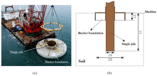
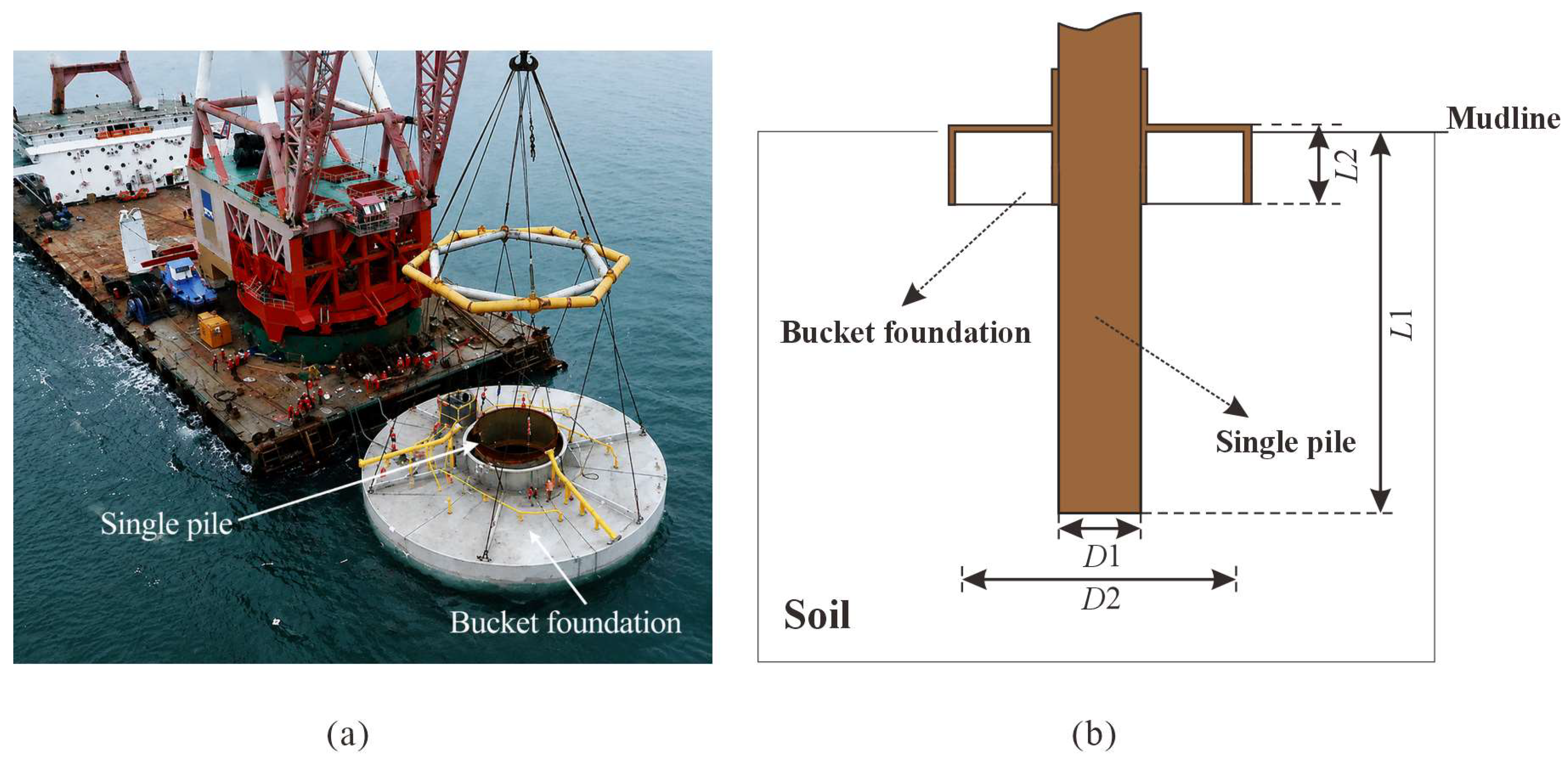
Recent progress in offshore wind technology has highlighted the need to enhance foundation performance under lateral loading. During operation, offshore wind turbine foundations are subjected to substantial overturning moments and horizontal forces resulting from wind, waves, and ocean currents [13,14]. As a result, their lateral response has become a crucial design consideration, as it is governed by complex soil–foundation interaction mechanisms [15,16,17,18]. To improve lateral capacity without resorting to excessively large monopile dimensions, hybrid foundation systems have attracted growing interest. Among these, pile–bucket foundations—shown in Figure 1—have demonstrated considerable promise by integrating the load-resisting features of both single piles and bucket foundations, while also mitigating the material and construction costs associated with oversized piles [19,20].
Figure 1.
Overview of the pile–bucket foundation: (a) site photograph [21,22,23]; (b) schematic diagram.
One of the earliest investigations into pile–bucket foundations was conducted by Bienen et al. [24], who examined a hybrid system comprising a skirted mat with an internal caisson under combined vertical, horizontal, and moment loading using three-dimensional finite element modeling. Subsequent research on pile–bucket systems subjected to both static and cyclic lateral loading has shown that these foundations are capable of mobilizing soil resistance more effectively than traditional monopiles [21,22,25]. Previous work has further indicated that both bucket diameter and embedment depth play significant roles in influencing moment-sharing behavior and overall lateral capacity [23,26]. In addition, the bucket element has been found to help dissipate excess pore water pressure under dynamic loading conditions [1,27]. More recently, research has explored the failure mechanisms of pile–bucket and pile–wheel composite foundations under combined vertical, lateral, and moment loading in layered soil profiles [28,29]. Meanwhile, modified p–y curve methods have been developed to account for the bucket’s contribution by applying equivalent lateral forces and moments at the pile head [30].
Recent research has continued to investigate pile–bucket foundations, demonstrating their potential to enhance lateral resistance compared with conventional single piles [1,26,31,32,33]. However, existing studies have predominantly focused on individual seabed conditions, limiting a comprehensive understanding of pile–bucket foundation behavior across different soil environments. Furthermore, systematic comparisons of the lateral response of pile–bucket foundations across multiple soil types within a consistent numerical framework remain scarce. In particular, how soil conditions and load eccentricity jointly influence load and moment redistribution between the pile and bucket components, rotation-center evolution, and soil failure mechanisms remains insufficiently understood. This issue is particularly relevant to offshore wind turbine foundations, where seabed conditions can vary significantly between sand- and clay-dominated deposits, resulting in considerable differences in soil stiffness, strength, and deformation characteristics. Therefore, a systematic evaluation of the effects of soil conditions and load eccentricity on the lateral behavior and failure mechanisms of pile–bucket foundations is needed to support reliable foundation design and performance assessment.
Scour around offshore wind turbine foundations can alter the seabed profile, reduce the effective embedment depth, and diminish the lateral soil support provided to the foundation. In addition, wave-induced loading can impose repeated lateral forces and overturning moments, potentially leading to accumulated deformation, changes in foundation stiffness, and evolving soil–foundation interaction. These effects are important considerations in assessing the overall performance of offshore foundations. The present study focuses on the static lateral response of pile–bucket foundations under different soil conditions and load eccentricities; therefore, scour evolution and cyclic wave loading are beyond the scope of the current investigation and warrant further study.
Against this background, the primary objective of this study is to investigate how soil conditions (medium sand, silty sand, and medium clay) and load eccentricity influence the static lateral behavior and failure mechanisms of pile–bucket foundations for offshore wind turbines. A three-dimensional finite element framework is employed to systematically evaluate the lateral bearing capacity, evolution of the rotation center, lateral load-sharing and moment-sharing ratios between the pile and bucket components, and soil deformation and failure mechanisms. The study also compares the performance of pile–bucket foundations with that of a single pile and a standalone bucket foundation to assess the benefits of the hybrid foundation system under different soil conditions. Through systematic comparisons across the selected soil conditions and load eccentricities, this study aims to clarify how these factors affect foundation capacity, rotational behavior, load-transfer mechanisms, and failure characteristics. The findings provide further insight into the static lateral performance of pile–bucket foundations and support their assessment and design for offshore wind turbine applications.
2. Numerical Modelling
This section outlines the numerical modeling methodology employed to examine the lateral response of pile–bucket foundations for offshore wind turbines under static loading. The study explores the influence of load eccentricity and three different soil types—medium sand, silty sand, and medium clay—on foundation performance, specifically in terms of lateral bearing capacity and associated soil failure mechanisms. All simulations were performed using the finite element software Abaqus 2022 [34].
2.1. Model Construction and Soil Properties
As shown in Figure 1, the pile–bucket foundation consists of a single pile (diameter D1, embedment depth L1) combined with a shallow bucket (diameter D2, embedment depth L2). The material properties adopted for the foundation are summarized in Table 1.
Table 1.
Mechanical properties for the pile–bucket foundation [1].
Three representative soil conditions, namely medium sand, silty sand, and medium clay, were selected to investigate the influence of soil properties on the lateral behavior of the pile–bucket foundation. The soil terminology follows EN ISO 14688-2:2017 [35], while BS 8004:2015 [36] was used as a reference for foundation engineering practice. In this study, the term “medium” in medium sand refers to the soil classification terminology rather than its mechanical strength or plasticity. Similarly, medium clay is used to identify a representative clay soil condition and does not imply a specific strength or plasticity classification. In this study, medium sand, silty sand, and medium clay were selected as representative soil conditions based on the adopted soil descriptions and corresponding mechanical properties. These designations are used to distinguish the soil conditions considered in the numerical investigation rather than to indicate that particle-size distribution or plasticity tests were conducted. The mechanical characteristics assigned to each soil type are presented in Table 2, Table 3 and Table 4. Medium sand and silty sand were modeled under drained conditions, following the approach adopted by Chen et al. [1]. Accordingly, their strength parameters are expressed in terms of effective cohesion (c’) and effective internal friction angle (Ø’). For medium sand, the actual effective cohesion of clean sand is generally assumed to be zero under drained conditions. However, an apparent cohesion of 10 kPa was assigned in the numerical model to improve numerical stability. This value represents a numerical modeling assumption rather than the actual effective cohesion of the sand. Medium clay was modeled under undrained conditions, with the cohesion parameter set equal to the undrained shear strength (su = 67) kPa and an internal friction angle (Ø) of 0°. The soil profile was assumed to be homogeneous and normally consolidated, and the Mohr–Coulomb constitutive model was adopted to represent soil behavior [34]. The unit weights adopted in the numerical model were 16.0 kN/m3 for medium sand, 8.7 kN/m3 for silty sand, and 16.5 kN/m3 for medium clay. The medium-sand and medium-clay values were calculated from the mass densities assigned in Abaqus (1600 and 1650 kg/m3, respectively), using a gravitational acceleration of 10 m/s2. The silty-sand value of 8.7 kN/m3 was adopted from Chen et al. [1], who reported it as the effective unit weight of soil representative of seabed conditions in Jiangsu Province, China. The geometric cases examined in the parametric study are detailed in Table 5.
The interaction between the foundation and the surrounding soil was modeled using a hard contact formulation in the normal direction, which permits separation and re-establishment of contact during loading. Tangential behavior was governed by a penalty-based Coulomb friction model, with friction coefficients set to 0.40 for medium sand [37], 0.33 for silty sand [38], and 0.31 for medium clay [39]. Surface-to-surface contact was employed throughout all analyses to enhance contact precision and numerical robustness. Following the modeling strategy outlined by Chen et al. [1], the self- weight of the tower, blades, and rotor–nacelle assembly was represented as a concentrated mass applied at the foundation top.
The Mohr–Coulomb constitutive model [34] was adopted because of its relatively simple formulation, computational efficiency, and ability to represent the principal soil strength characteristics governing the static lateral response of pile–bucket foundations. As the present study focuses on the effects of soil type and load eccentricity under static conditions, the model provides a suitable framework for examining soil–foundation interaction, deformation patterns, and failure mechanisms. Its computational efficiency also facilitates a systematic parametric investigation of different foundation configurations and soil conditions. However, the conventional Mohr–Coulomb model [34] has important limitations in representing the actual behavior of offshore soils under cyclic or dynamic loading. In particular, it does not explicitly capture cyclic hysteresis, stiffness degradation, or the progressive accumulation of irreversible plastic strains. Furthermore, excess pore-water pressure generation and dissipation are not considered in the present study. Consequently, the model cannot predict pore-pressure-induced liquefaction or its associated effects on effective stress and soil stiffness. The results should therefore be interpreted as predictions of static lateral behavior under the adopted constitutive and loading assumptions, rather than as a complete representation of foundation response to time-varying or cyclic wave loading. Under actual offshore conditions, wave-induced cyclic loading may cause changes in soil stiffness and strength, permanent deformation, and pore-pressure development, thereby influencing the long-term foundation response. These effects are beyond the scope of the present investigation. Future research should consider advanced cyclic soil constitutive models and coupled hydro-mechanical analyses to examine these mechanisms and provide a more comprehensive assessment of offshore foundation behavior.
The comparison among medium sand, silty sand, and medium clay is intended to examine the lateral response of the pile–bucket foundation under three representative soil conditions. Because the selected soils have different mechanical properties, the observed variations in lateral bearing capacity, rotation-center location, load-sharing behavior, and failure mechanisms reflect the combined effects of soil strength, stiffness, and constitutive behavior. Accordingly, these comparisons should not be interpreted as isolating the independent influence of soil classification. Further investigations involving systematic variations in individual soil parameters would be required to quantify their respective contributions to foundation performance.
Table 2.
Soil parameters adopted for medium sand [40,41,42].
Table 3.
Soil parameters adopted for silty sand [1].
Table 4.
Soil parameters adopted for medium clay [40,42,43].
Table 5.
Geometric parameters adopted in the parametric study.
2.2. Meshes
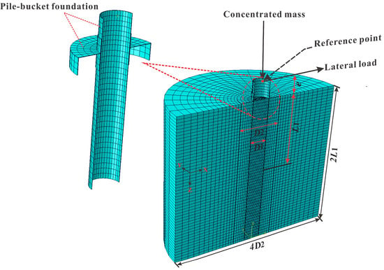
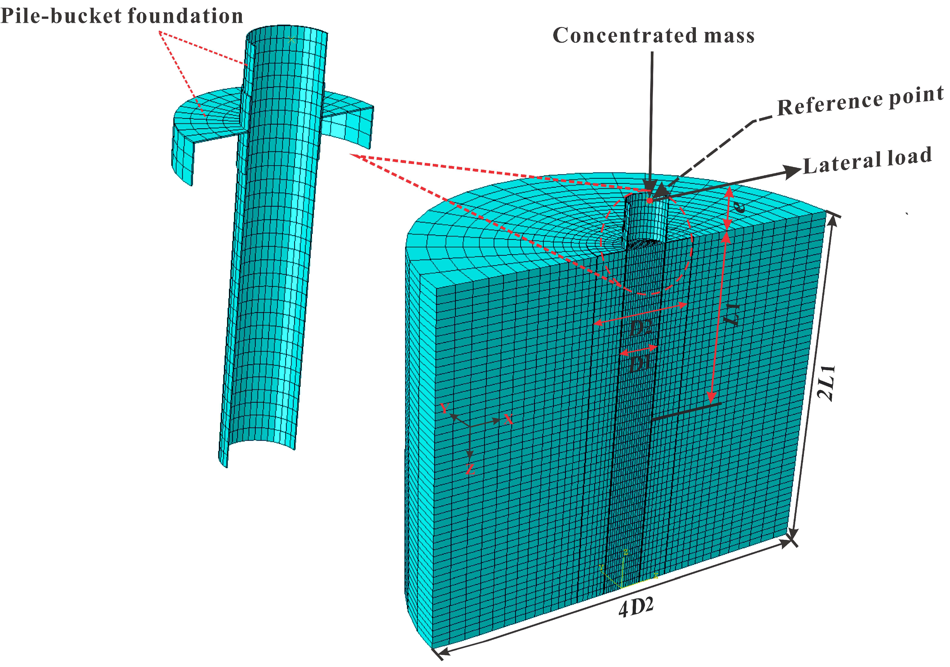
A half-model was employed by taking advantage of the symmetry inherent in both the foundation geometry and the loading configuration, as shown in Figure 2. The soil domain was treated as homogeneous and isotropic, with a diameter of 4D2 and a depth of 2 L1, consistent with the validated numerical model of Frah et al. [26]. Regarding boundary conditions, a symmetry constraint was applied along the symmetry plane of the model. The base was fully fixed, while horizontal movements in both the x- and y-directions were prevented at the lateral boundaries.
Figure 2.
Finite element model of the pile–bucket foundation and soil domain.
The pile–bucket foundation and the surrounding soil were discretized using eight-node hexahedral solid elements with reduced integration (C3D8R). The soil domain size and boundary conditions were based on the boundary sensitivity analysis conducted by Frah et al. [26], which confirmed that the selected domain dimensions were adequate to minimize boundary interference with the foundation response.
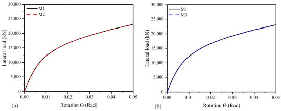
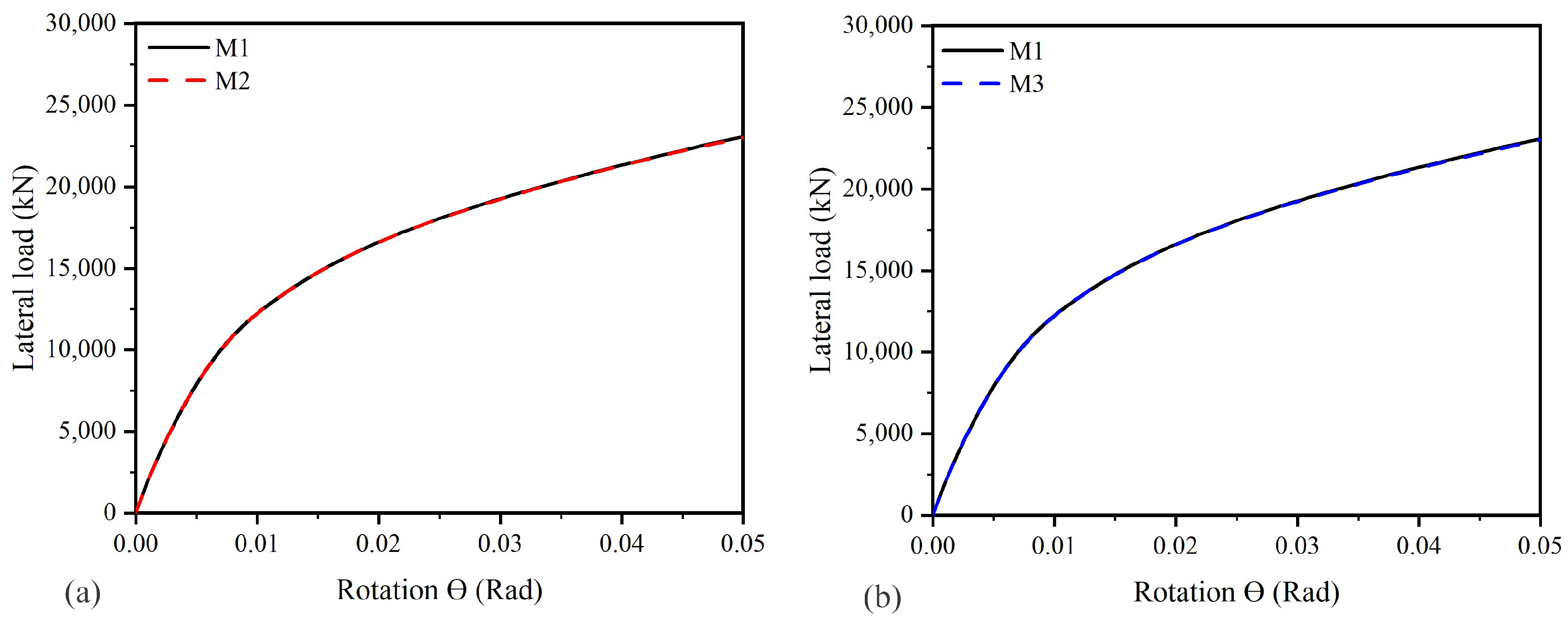
A mesh-sensitivity analysis was performed to evaluate the influence of mesh refinement on the predicted lateral response of the pile–bucket foundation, as shown in Figure 3. The model geometry, soil properties, loading conditions, and boundary conditions were kept identical across all simulations, while only the mesh configuration was varied. Three mesh configurations (M1, M2, and M3), comprising 10, 12, and 14 elements along the specified edge, respectively, were compared. The corresponding element-size ranges were 0.54–2.70 m, 0.43–2.16 m, and 0.36–1.80 m, respectively. The predicted ultimate lateral loads were 23,261.6 kN, 23,200.5 kN, and 23,176.9 kN for M1, M2, and M3, respectively. Relative to M1, the ultimate lateral load decreased by approximately 0.26% for M2 and 0.36% for M3. Furthermore, the load–rotation curves were nearly coincident, indicating that the predicted lateral response was relatively insensitive to mesh refinement over the range investigated. Accordingly, M1 was selected for the subsequent analyses because it provided comparable predictions with a coarser mesh and lower computational cost.
Figure 3.
Mesh-sensitivity analysis of the pile–bucket foundation: comparison of load–rotation curves for mesh configurations M1, M2, and M3: (a) M1 versus M2; (b) M1 versus M3.
2.3. Model Validation
The finite element modeling framework adopted in this study was previously validated by [26] through comparisons with the numerical results of [1] and the centrifuge test data presented by [22]. The validation results demonstrated that the adopted modeling approach could effectively capture the lateral load–displacement and moment–rotation responses of pile–bucket foundations under lateral loading.
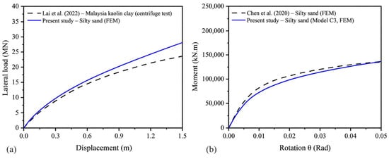
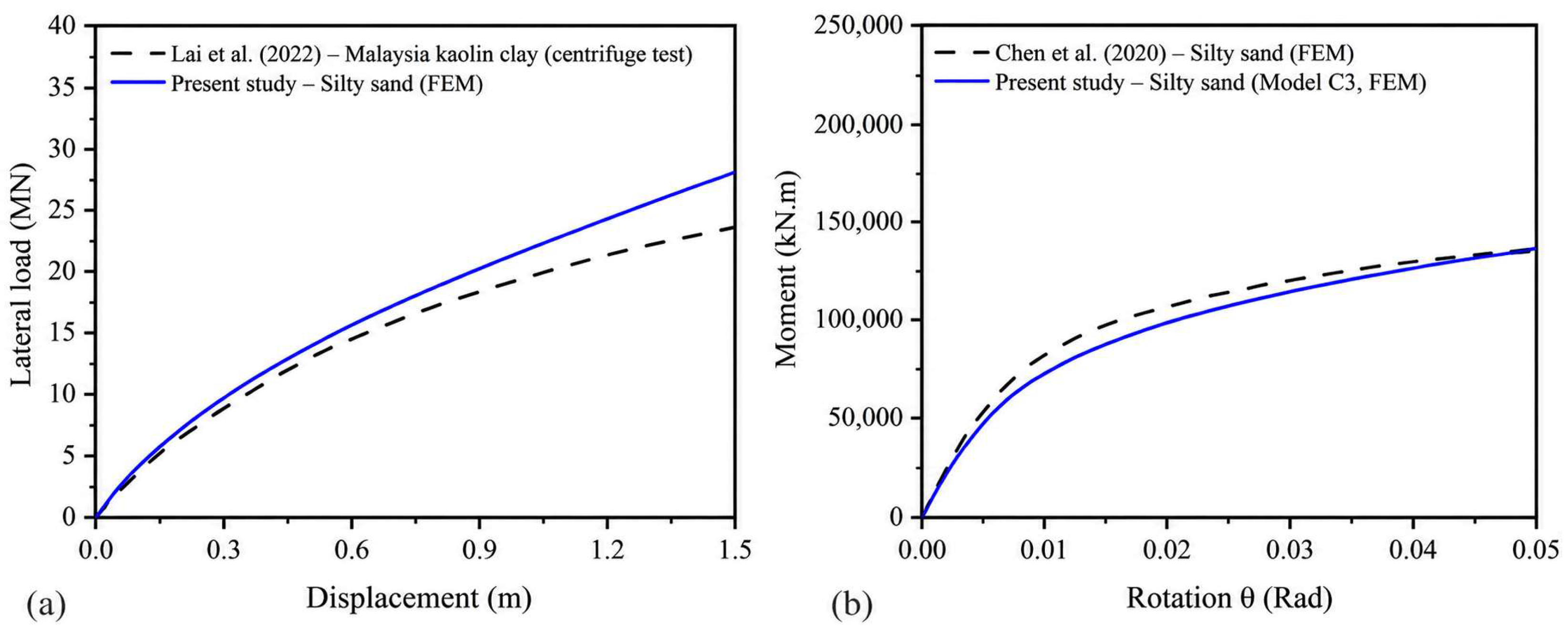
To further demonstrate the reliability of the numerical framework adopted in the present study, the validation cases were reproduced using the same pile–bucket geometry and numerical settings. Figure 4a compares the predicted moment–rotation response from the present model with the numerical results reported by [1], while Figure 4b compares the predicted lateral load–displacement response with the centrifuge test results reported by [22]. The predicted moment–rotation response shows good agreement with the results of [1], with a relative difference of approximately 1.8% in the ultimate moment. Similarly, the predicted lateral load–displacement response follows the experimental trend observed in [22], indicating that the adopted model reasonably captures the nonlinear lateral response of pile–bucket foundations for the validation case considered.
Figure 4.
Validation of the finite element model: (a) comparison of the moment–rotation response with [1]; (b) comparison of the lateral load–displacement response with [22] centrifuge test results.
The present study adopts the same finite element formulation, constitutive model, soil–structure interface properties, boundary conditions, and loading procedures as those described in [26]. Therefore, the validated framework was extended to investigate the coupled effects of load eccentricity and soil type on the lateral response, load-transfer mechanism, and failure behavior of pile–bucket foundations embedded in medium sand, silty sand, and medium clay.
2.4. Test Arrangements
In the present study, five numerical models were developed to examine the influence of load eccentricity and soil type on the performance of pile–bucket foundations. Models C1 and C2 correspond to a single pile and an isolated bucket foundation, respectively, both sharing the same geometric dimensions as the pile–bucket system in Model C3 (Table 5). Models C3, C4, and C5 represent pile–bucket foundations subjected to lateral loading at varying load eccentricities. All models were analyzed under three representative soil conditions—medium sand, silty sand, and medium clay—to assess the effect of soil type on lateral response and failure behavior. For the purpose of comparison, the ultimate lateral bearing capacity was defined as the lateral load corresponding to a foundation rotation of 0.05 rad [1]. This criterion ensures a consistent basis for evaluating the lateral performance of the different foundation systems under displacement-controlled loading.
3. Numerical Results
3.1. Lateral Bearing Capacity
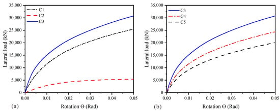
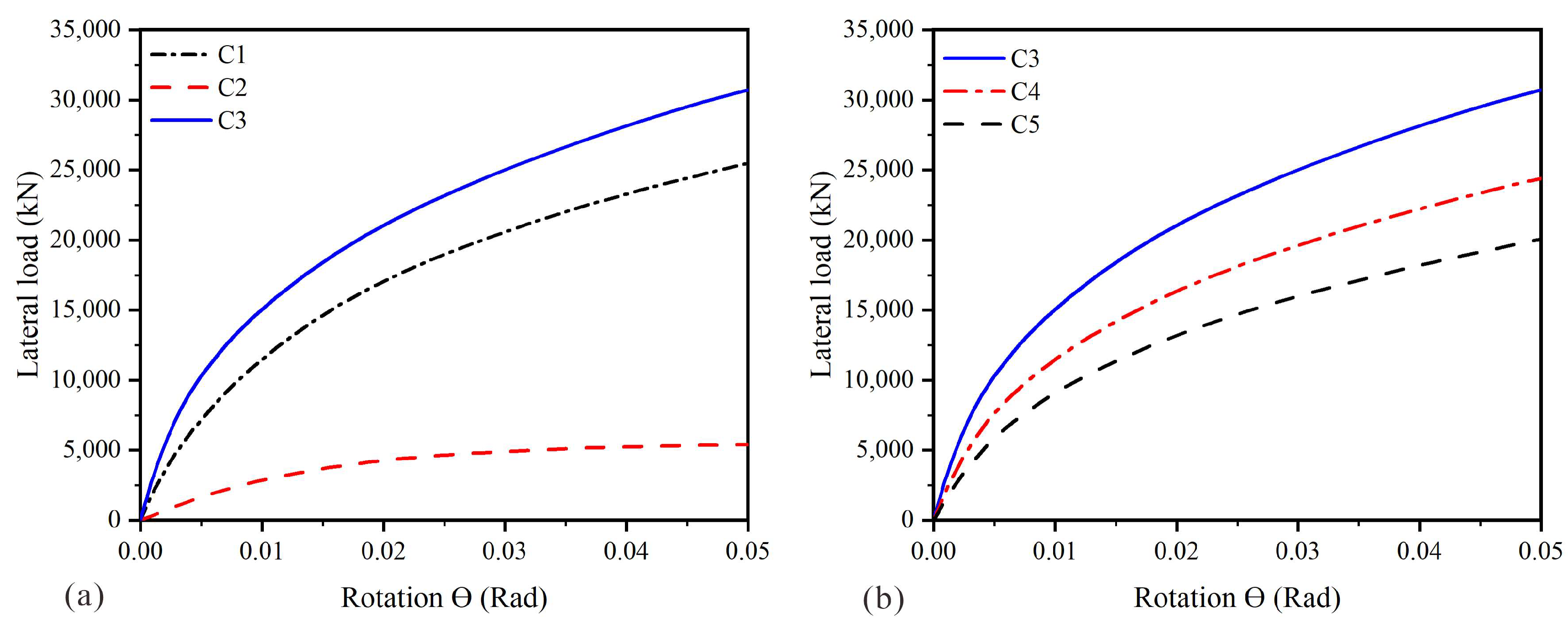
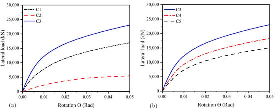
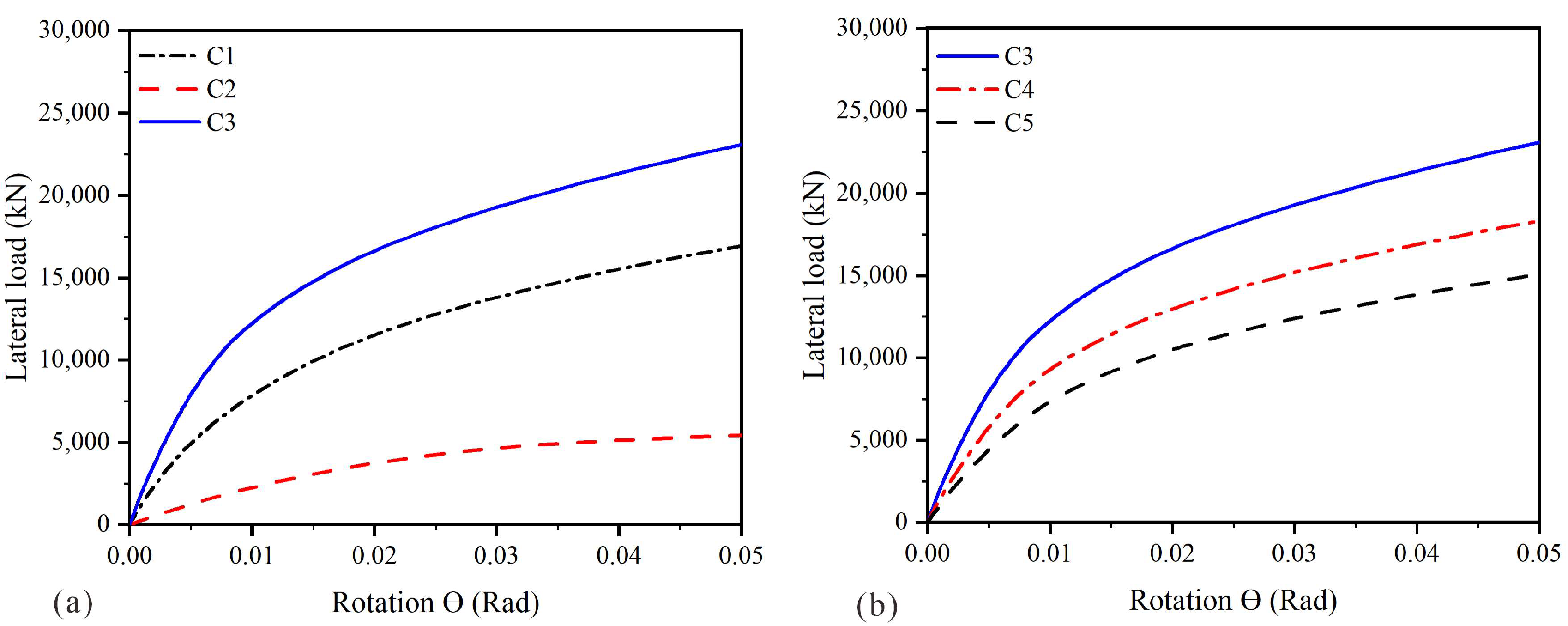
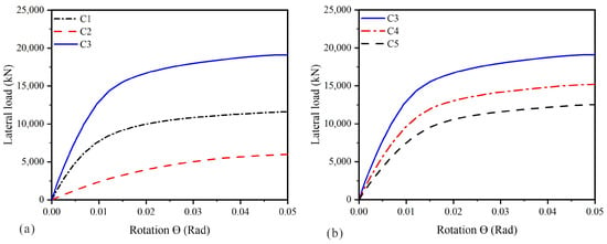
Figure 5, Figure 6 and Figure 7 illustrate the lateral load–rotation responses of pile–bucket foundations under different soil conditions and load eccentricities. As shown in Figure 5a, Figure 6a and Figure 7a, the pile–bucket foundation exhibits a higher lateral bearing capacity than both the single pile and the standalone bucket foundation under all three soil conditions. The lateral bearing capacity was quantified from the numerically obtained lateral load–rotation curves using a common foundation rotation criterion of 0.05 rad [1]. Relative to the single pile, the capacity increased by approximately 19.4%, 37%, and 64% in medium sand, silty sand, and medium clay, respectively. Compared with the standalone bucket foundation, the capacity was approximately 5.7, 4.0, and 3.0 times greater, respectively. These results demonstrate the enhanced lateral resistance of the combined foundation system, which benefits from the interaction between the pile, bucket, and surrounding soil.
Figure 5.
Lateral load–rotation response of the pile–bucket foundation in medium sand.
Figure 6.
Lateral load–rotation response of the pile–bucket foundation in silty sand.
Figure 7.
Lateral load–rotation response of the pile–bucket foundation in medium clay.
Among the three soil conditions examined, medium sand exhibits the highest initial stiffness and lateral bearing capacity, followed by silty sand and medium clay. This trend is consistent with the differences in the mechanical properties assigned to the selected soils, particularly their stiffness and shear-strength characteristics. Therefore, the observed differences represent the combined response of the foundation–soil systems under the adopted material parameters rather than the isolated effect of soil classification.
The influence of load eccentricity on the lateral bearing capacity is illustrated in Figure 5b, Figure 6b and Figure 7b. Compared with the reference model (C3), the lateral bearing capacity decreases progressively as the load eccentricity increases in Models C4 and C5, with reductions ranging from approximately 20% to 34% across the three soil conditions. The larger overturning moments associated with increasing load eccentricity promote greater foundation rotation, thereby reducing the effective lateral resistance of the foundation system. Similar trends have been reported in previous numerical and experimental studies [26,33,44].
From an engineering perspective, this indicates that offshore wind turbine foundations installed in medium clay seabeds require greater consideration of load eccentricity effects, as the relatively lower stiffness and higher deformability of medium clay can accelerate rotational deformation and lead to a more significant reduction in lateral performance.
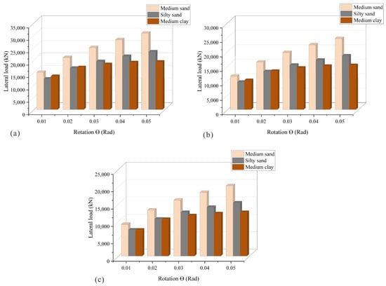
Figure 8 compares the lateral load–rotation responses of Models C3, C4, and C5 in medium sand, silty sand, and medium clay. For all three soil conditions, the lateral load increases progressively with foundation rotation. However, the magnitude of the response varies according to the soil type. Medium sand consistently exhibits the greatest lateral resistance, followed by silty sand and medium clay. This trend reflects the higher stiffness and frictional resistance of medium sand, which enable more effective mobilization of lateral soil resistance and greater resistance to foundation rotation.
Figure 8.
Lateral load–rotation response of the pile–bucket foundation under different soil conditions for (a) Model C3, (b) Model C4, and (c) Model C5.
The effect of load eccentricity is evident under all soil conditions. As the load eccentricity increases from Model C3 to Model C5, the lateral bearing capacity decreases progressively because the larger eccentricity produces greater overturning moments. Consequently, foundation rotation increases, reducing the effective lateral resistance of the pile–bucket foundation. Among the loading cases considered, Model C3 exhibits the highest lateral bearing capacity, whereas Model C5 provides the lowest. The reduction in bearing capacity is most pronounced in medium clay, reflecting its relatively low stiffness and greater susceptibility to deformation.
3.2. Soil Failure Mechanisms and Rotation Center Development
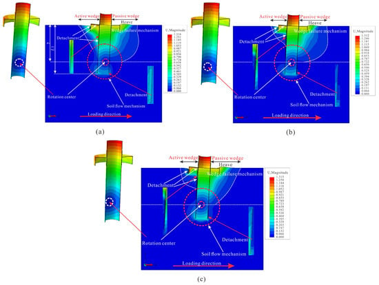
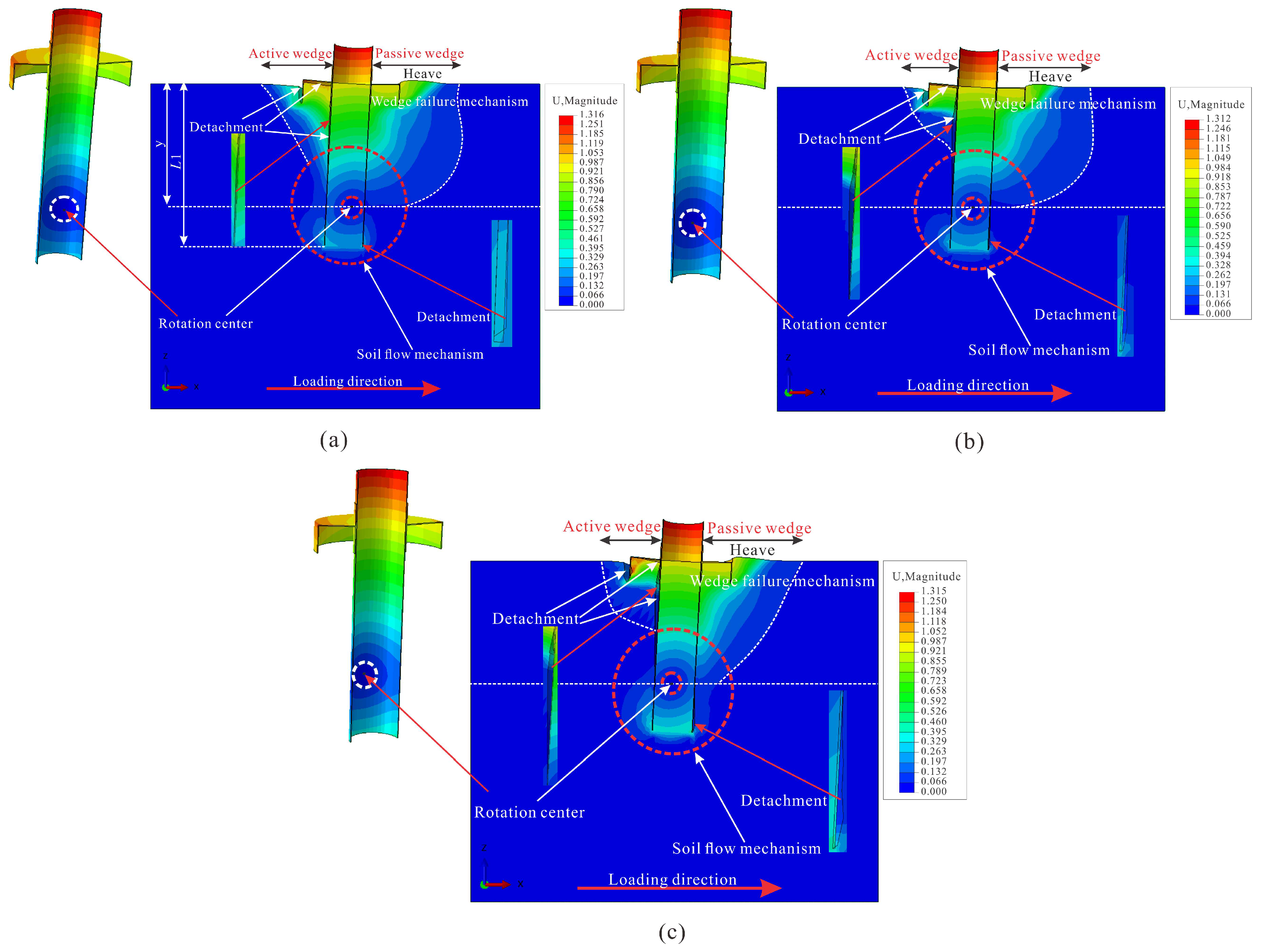
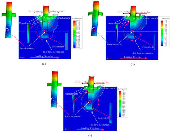
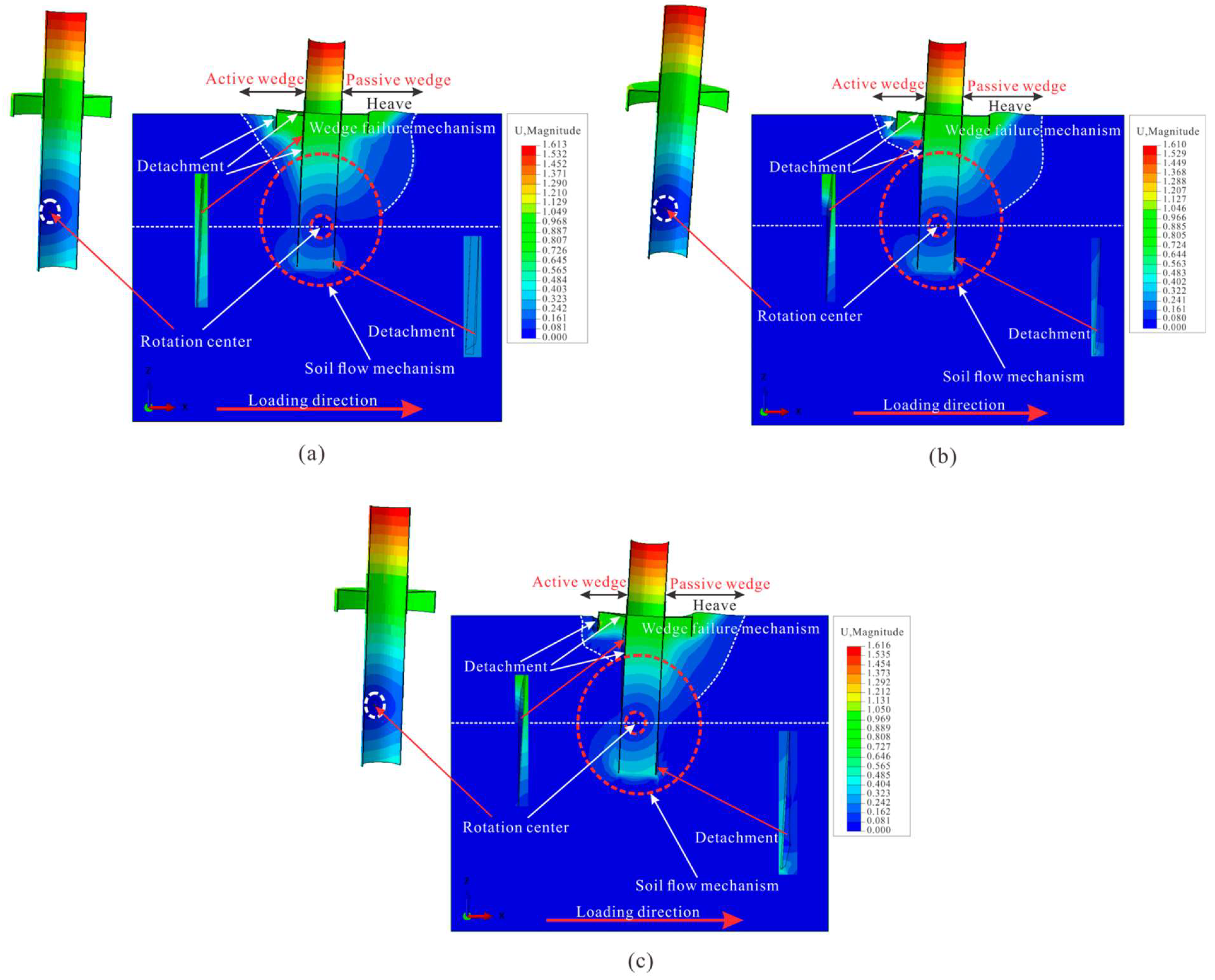
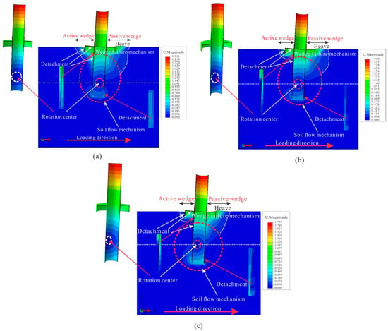
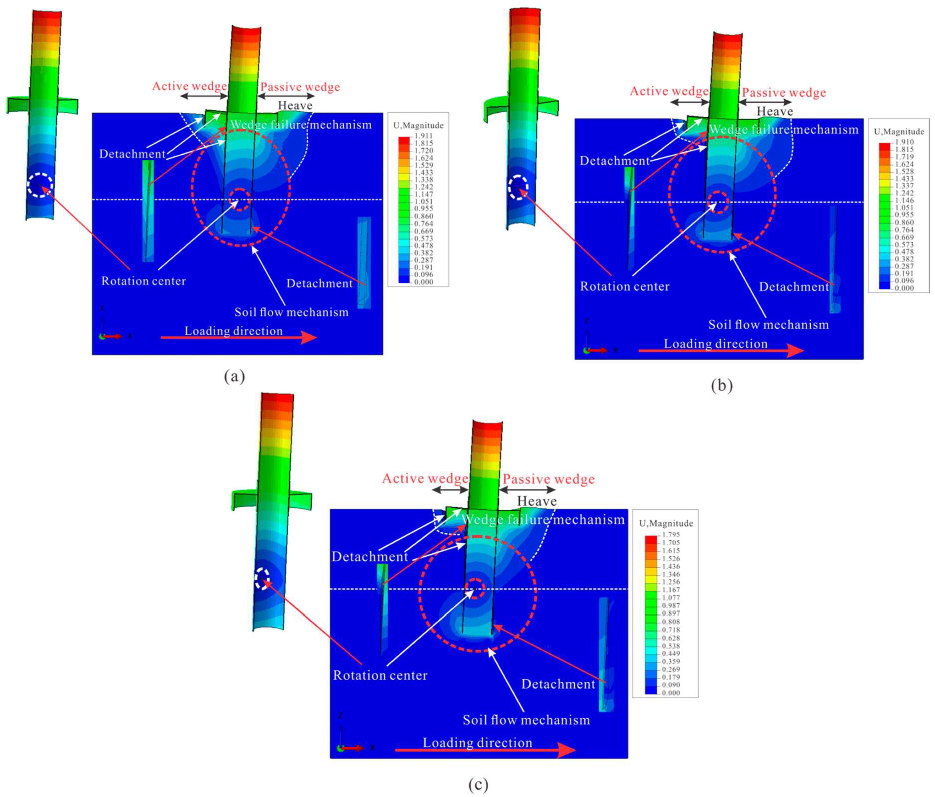
The location of the rotation center is commonly acknowledged as a key factor influencing the lateral response of pile foundations [18,45]. Figure 9, Figure 10 and Figure 11 present displacement contours that depict the deformation behavior of the pile–bucket foundation under various load eccentricities in medium sand, silty sand, and medium clay, at a foundation rotation of 0.05 rad. These contours offer useful insights into the evolution of soil failure mechanisms during lateral loading [46].
Figure 9.
Displacement contours illustrating the failure mechanisms of the pile–bucket foundation and surrounding soil for Model C3 at a foundation rotation angle of 0.05 rad: (a) medium sand, (b) silty sand, and (c) medium clay.
Figure 10.
Displacement contours illustrating the failure mechanisms of the pile–bucket foundation and surrounding soil for Model C4 at a foundation rotation angle of 0.05 rad: (a) medium sand, (b) silty sand, and (c) medium clay.
Figure 11.
Displacement contours illustrating the failure mechanisms of the pile–bucket foundation and surrounding soil for Model C5 at a foundation rotation angle of 0.05 rad: (a) medium sand, (b) silt sand, and (c) medium clay.
Across all loading cases and soil types, the pile–bucket foundation displays a rotation-dominated failure mode. Two distinct deformation patterns are evident around the rotation center, which is situated in the lower section of the pile. The first involves a wedge-shaped failure zone forming near the mudline, while the second consists of rotational soil displacement occurring in the deeper soil around the embedded foundation. These failure characteristics are consistent with those documented by [18,26,33,45]. The normalized depth of the rotation center is defined as y/L1, where y is the rotation-center depth and L1 is the embedment d length of the single pile in the pile–bucket foundation, as depicted in Figure 9a.
For Model C3 (Figure 9a–c), the pile–bucket foundation exhibits a rotation-dominated failure mechanism, characterized by wedge-shaped soil deformation near the mudline and rotational soil displacement in the deeper embedded region. The extent of deformation depends on the soil properties. In medium sand, deformation remains relatively localized, with clearly defined active and passive failure wedges. In silty sand, the deformation zone becomes wider, accompanied by more pronounced soil movement around the bucket edge. Medium clay exhibits the most extensive deformation, including wider failure wedges, greater surface heave, and more substantial soil detachment. As the load eccentricity increases in Models C4 and C5, the deformation zones enlarge and the rotation center migrates upward, particularly in medium clay. Nevertheless, the overall rotation-dominated failure mechanism remains unchanged.
Under Model C4 (Figure 10a–c, increasing load eccentricity causes the rotation center to migrate upward while enlarging the passive failure wedge. In medium sand, the passive wedge remains clearly defined, although localized separation develops near the pile tip. For silty sand and medium clay, rotational soil movement becomes more pronounced around the lower portion of the pile, indicating greater deformation and increased mobilization of soil resistance within the deeper soil layers.
For Model C5 (Figure 11a–c, the highest load eccentricity causes the rotation center to shift further upward toward the bucket edge, accompanied by the full formation of the wedge-shaped failure pattern. In medium sand, the active and passive wedges remain clearly distinguishable, although the deformed zone extends beyond the bucket diameter. In silty sand, larger areas of soil detachment and more pronounced surface heave are evident. Medium clay exhibits the most extensive deformation, with substantial soil movement occurring on both sides of the pile, confirming that rotational displacement governs the overall foundation response.
3.3. Rotation-Center Evolution
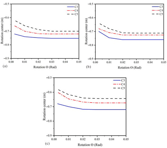
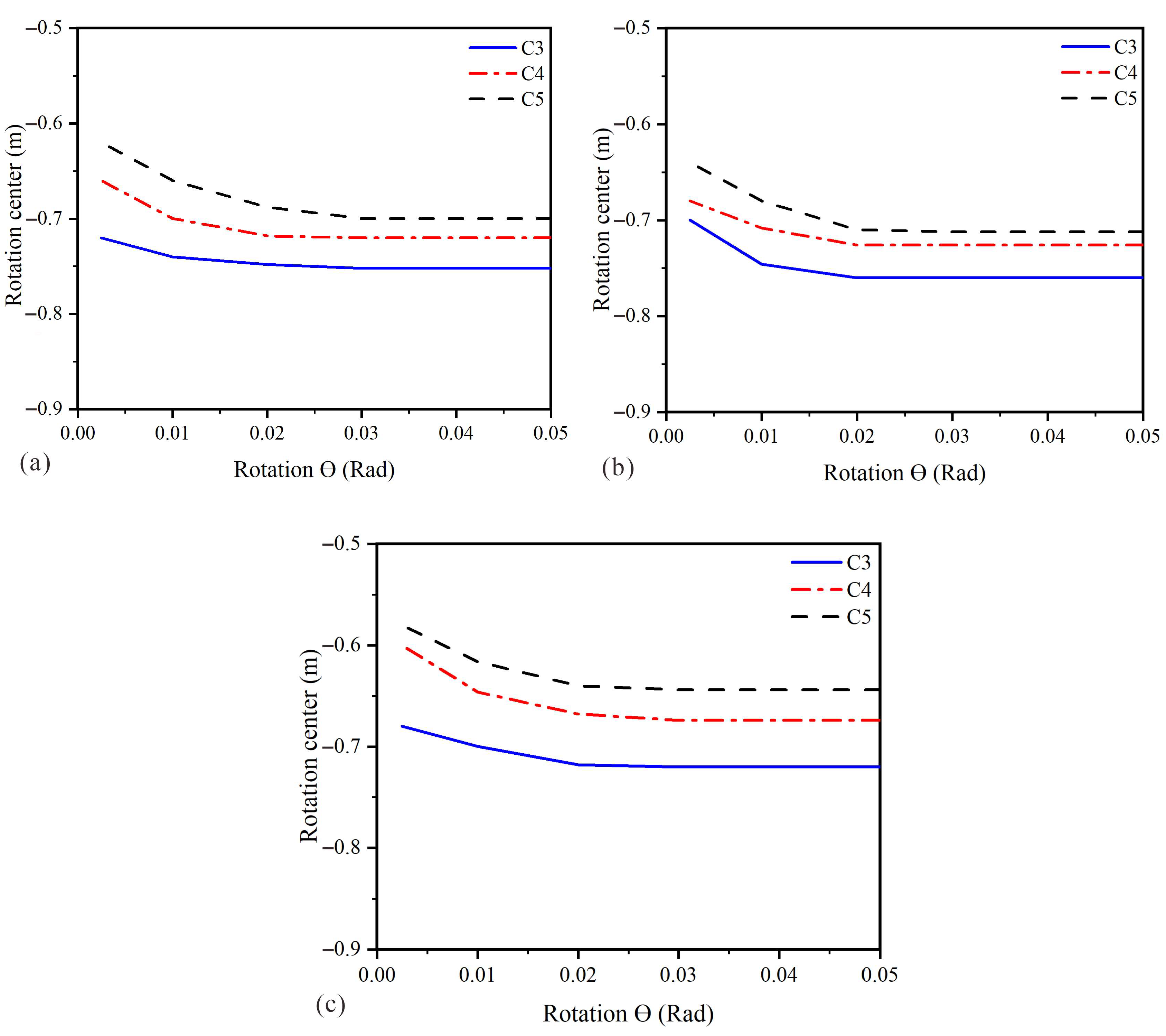
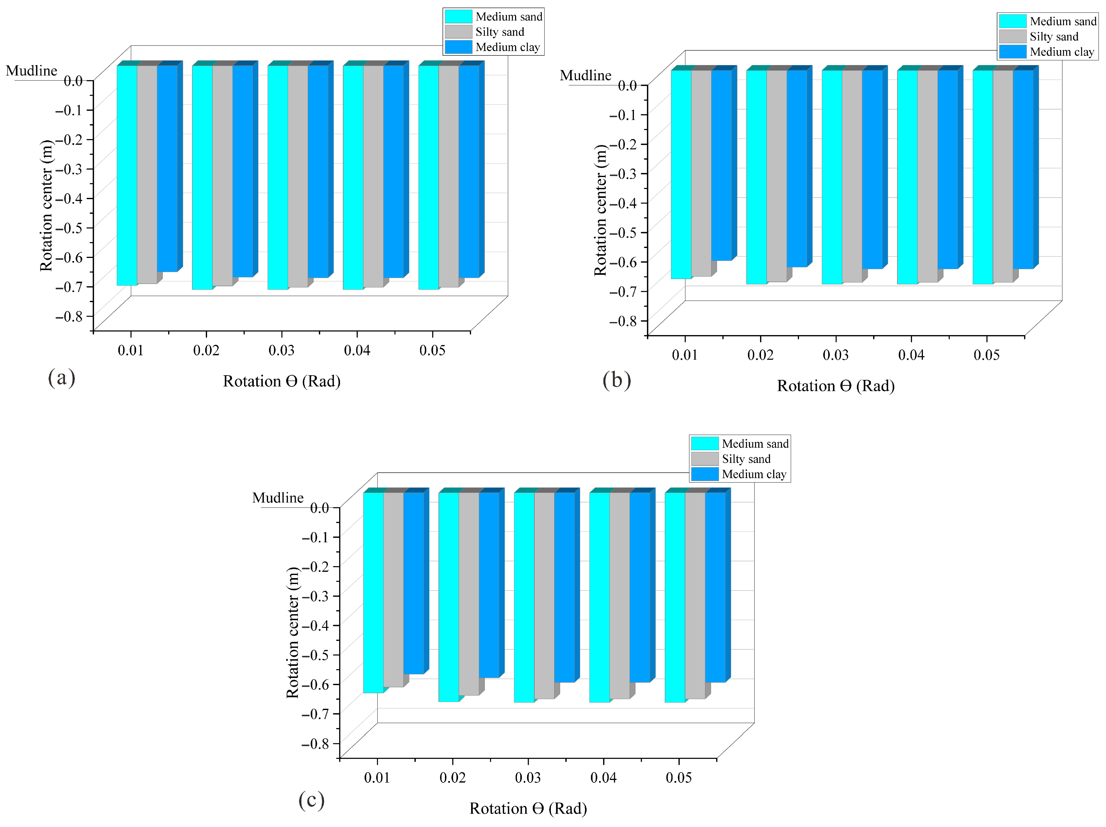
The variation in the rotation-center location under different soil conditions and load eccentricities is presented in Figure 12 and Figure 13. The vertical position of the rotation center, y, is measured relative to the mudline. The normalized vertical coordinate of the rotation center is defined as y/L1, where L1 is the embedment length of the single pile in the pile–bucket foundation. Negative values indicate that the rotation center is located below the mudline. For all soil types, the rotation center gradually migrates upward as the load eccentricity increases from Model C3 to Model C5, indicating that foundation rotation be-comes increasingly concentrated within the upper embedded portion of the foundation.
Figure 12.
Rotation-center variation in the pile–bucket foundation in (a) medium sand, (b) silty sand, and (c) medium clay.
Figure 13.
Variation in rotation-centre location for the pile–bucket foundation under different soil conditions: (a) Model C3, (b) Model C4, and (c) Model C5.
Among the three soil conditions, the deepest rotation center is observed in medium sand, followed by silty sand and medium clay. The greater rotation-center depth in medium sand is attributed to its relatively higher stiffness and frictional resistance, which promote more effective mobilization of soil resistance along both the pile shaft and the bucket skirt. In contrast, the shallower rotation centers observed in silty sand and medium clay indicate lower resistance to rotation and greater deformation within the upper soil layers.
The quantitative variation in rotation-center depth is illustrated in Figure 13. For Model C3, the deepest rotation center occurs in medium sand at approximately −0.76 m, followed by silty sand (−0.75 m) and medium clay (−0.72 m). As the load eccentricity increases from Model C3 to Model C5, the rotation center shifts progressively upward toward the ground surface under all three soil conditions. The upward migration is approximately 4–7% in medium sand and silty sand and 6–8.5% in medium clay. The greater upward migration observed in medium clay indicates that the rotation-center position is more sensitive to increasing load eccentricity in this soil. This behavior suggests that rotational deformation becomes increasingly concentrated in the upper embedded portion of the foundation as the load eccentricity increases.
3.4. Lateral Load- and Moment-Sharing Ratios
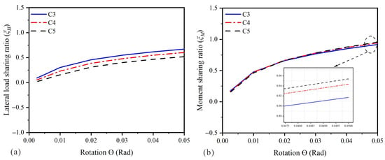
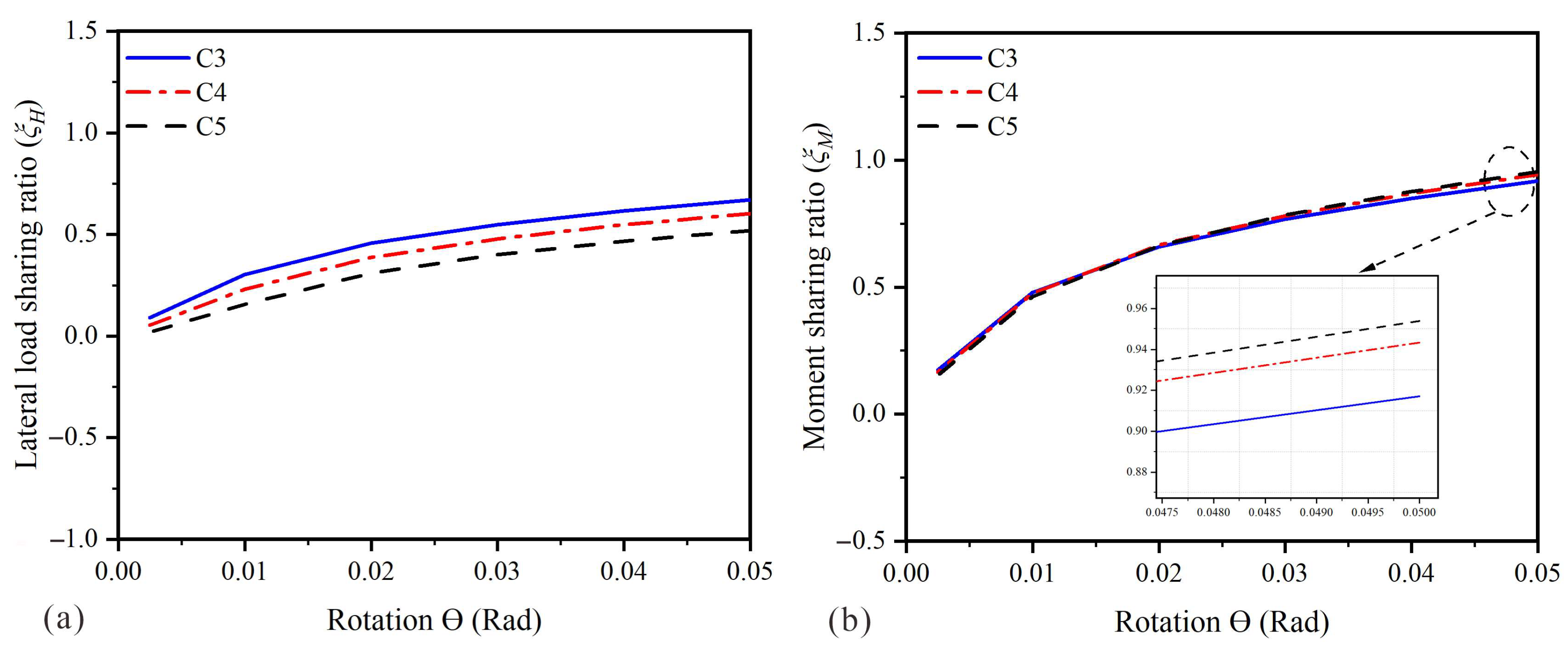
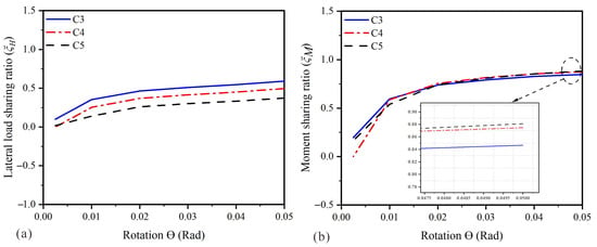
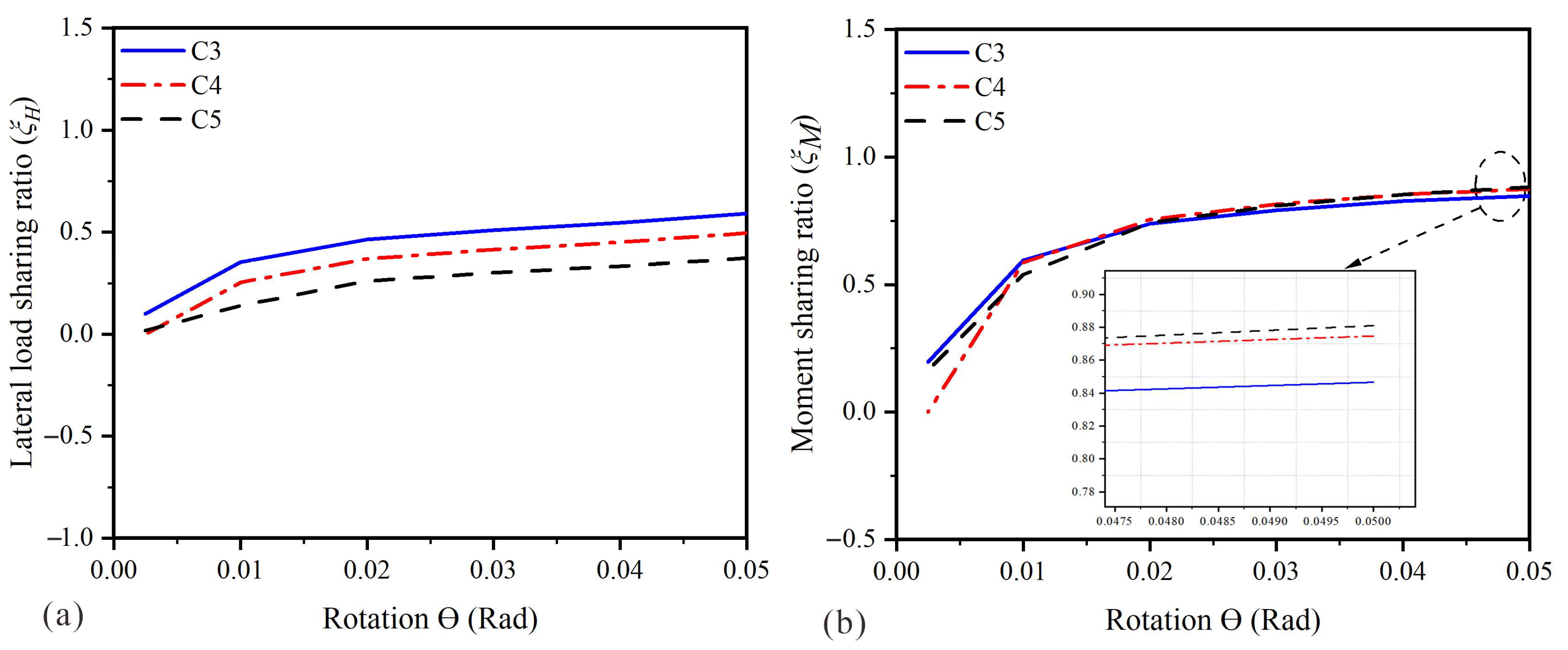
This section examines the individual contributions of the pile and bucket components to the lateral load resistance of the pile–bucket foundation. Following the definitions proposed in [1,23], the lateral load-sharing ratio ξH and moment-sharing ratio ξM are used to quantify the contributions of the pile component to the total lateral load and overturning moment resisted by the pile–bucket system, respectively. The lateral load-sharing ratio is defined as the ratio of the lateral load carried by the pile component at the mudline HP to the total lateral load applied at the top of the foundation H. The moment-sharing ratio is defined as the ratio of the moment resisted by the pile component at the mudline MP to the total moment developed at the mudline due to the applied lateral load M. These ratios are expressed as follows:
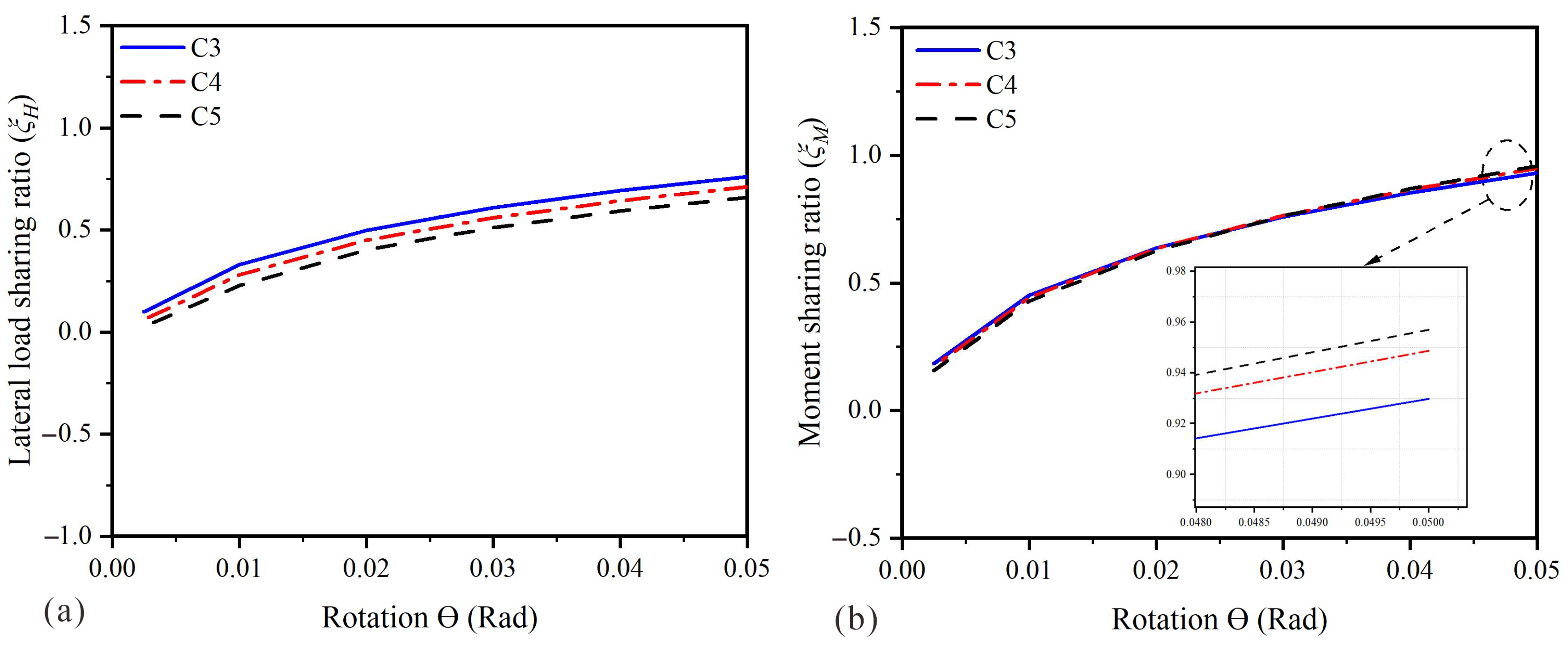
Figure 14, Figure 15 and Figure 16 present the influence of soil type and load eccentricity on the variation in the lateral load-sharing ratio (ξH) and moment-sharing ratio (ξM). Overall, both ratios rise with increasing foundation rotation and tend to level off toward steady values, reflecting the gradual mobilization of soil resistance and the redistribution of lateral load and moment between the pile and bucket components.
Figure 14.
Influence of load eccentricity in medium sand on (a) the lateral load-sharing ratio (ξH) and (b) the moment-sharing ratio (ξM).
Figure 15.
Influence of load eccentricity in silty sand on (a) lateral load-sharing ratio (ξH) and (b) moment-sharing ratio (ξM).
Figure 16.
Influence of load eccentricity in medium clay on (a) lateral load-sharing ratio (ξH) and (b) moment-sharing ratio (ξM).
The lateral load-sharing ratio (ξH) Figure 14a, Figure 15a and Figure 16a decreases as load eccentricity increases under all soil conditions, indicating that the contribution of the pile component to the overall lateral resistance becomes smaller. For Models C3–C5, the maximum value of ξH decreases from approximately 0.76 to 0.66 in medium sand, 0.67 to 0.52 in silty sand, and 0.59 to 0.37 in medium clay. Consequently, the bucket component contributes an increasingly larger proportion of the lateral resistance as load eccentricity increases.
Conversely, the moment-sharing ratio (ξM) shows the reverse trend. As seen in Figure 14b, Figure 15b and Figure 16b, the portion of the applied moment resisted by the pile grows with increasing load eccentricity. The maximum ξM values range from approximately 0.93 to 0.96 in medium sand, 0.92 to 0.95 in silty sand, and 0.85 to 0.88 in medium clay. These findings indicate that the pile remains the dominant component in resisting the applied overturning moment, while the bucket primarily contributes to shallow lateral resistance.
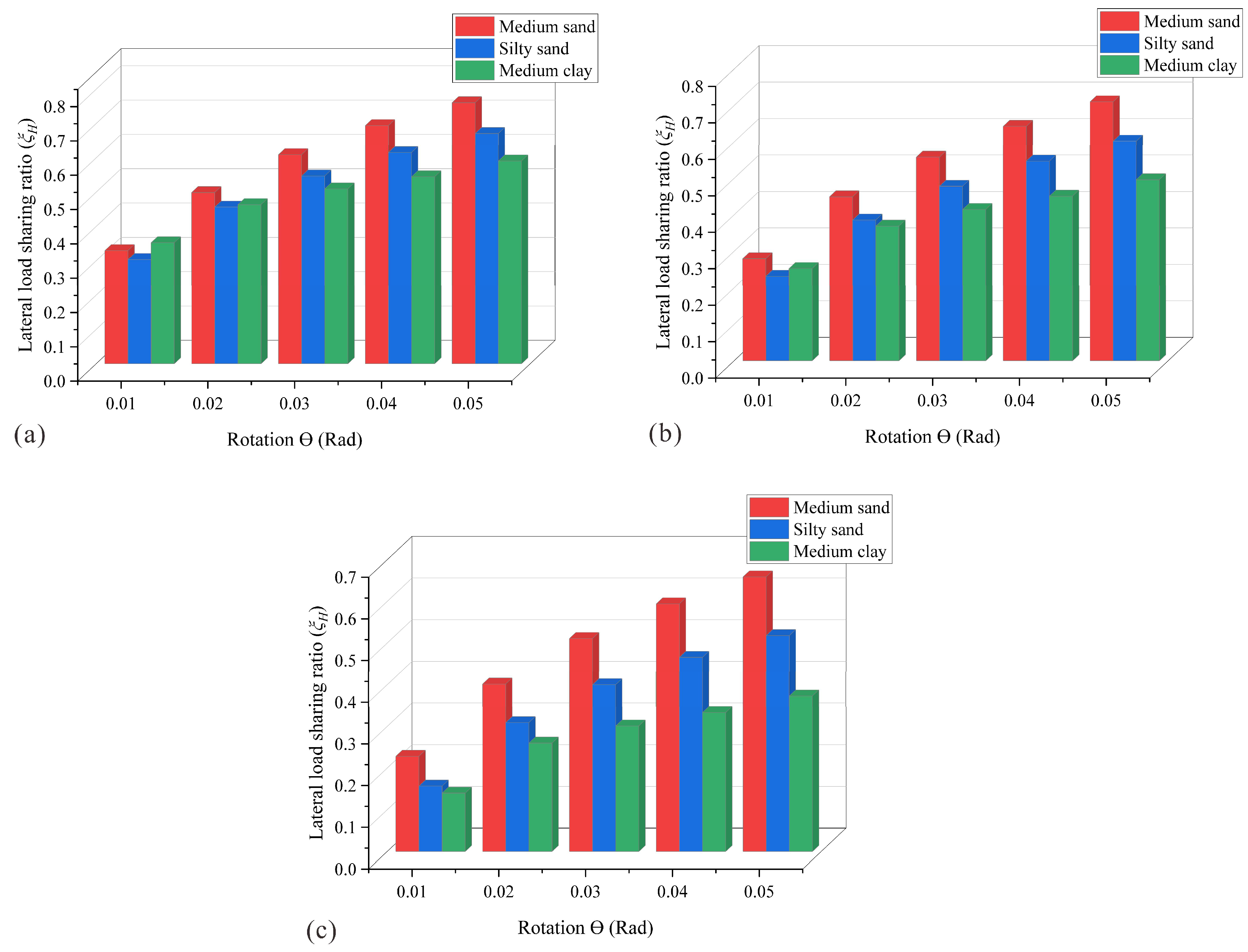
The variation in the lateral load-sharing ratio for Models C3, C4, and C5 under different soil conditions is compared in Figure 17. For all three soil types, ξH increases with foundation rotation before approaching a stable value. Medium sand consistently exhibits the highest lateral load-sharing ratio, followed by silty sand and medium clay. As the load eccentricity increases from Model C3 to Model C5, ξH decreases by approximately 6–13% in medium sand, 10–22% in silty sand, and 15–37% in medium clay. The more pronounced reduction observed in medium clay indicates that this soil is more sensitive to load eccentricity. As the rotation center migrates upward, the contribution of the pile to the overall lateral resistance decreases, while the relative contribution of the bucket increases. This behavior can be attributed to the reduced mobilization of deeper pile resistance caused by the upward shift of the rotation center. Consequently, the shallow bucket component becomes increasingly important in providing lateral resistance, particularly under highly eccentric loading conditions.
Figure 17.
Variation in the lateral load-sharing ratio of the pile–bucket foundation under different soil conditions for (a) Model C3, (b) Model C4, and (c) Model C5.
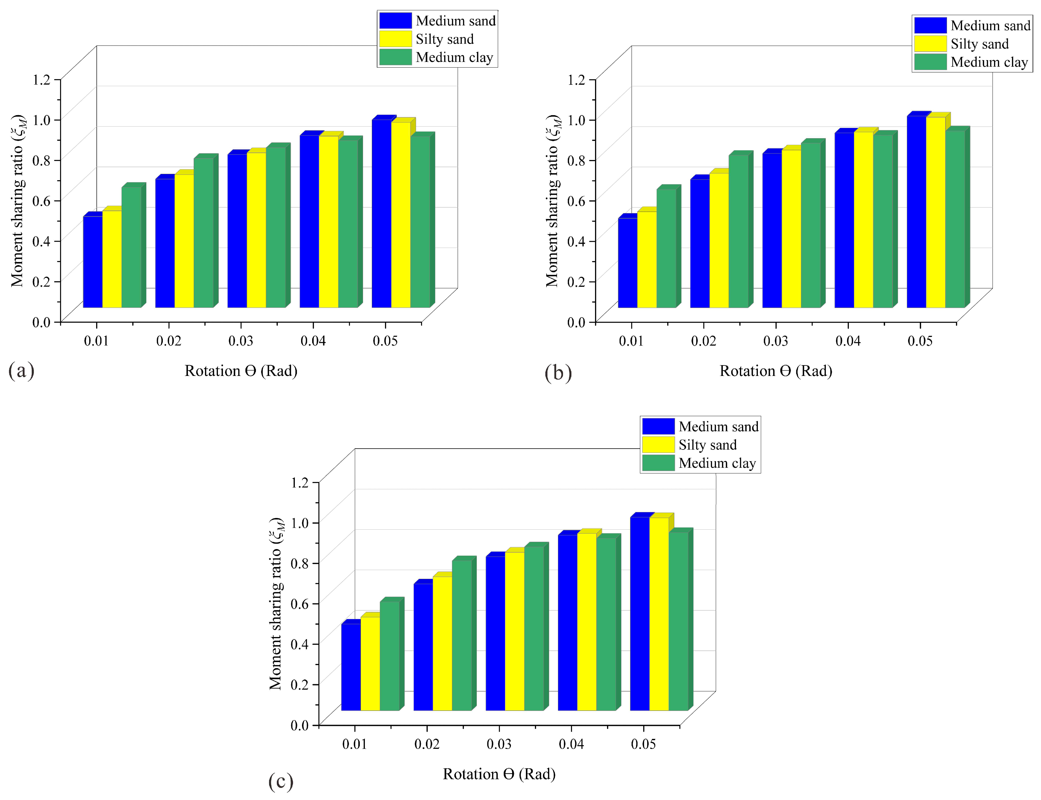
The variation in the moment-sharing ratio (ξM) for Models C3, C4, and C5 under different soil conditions is presented in Figure 18. For all three soil types, ξM increases progressively with foundation rotation before gradually reaching a stable value, reflecting the continuous mobilization of pile resistance during loading. Compared with Model C3, Models C4 and C5 exhibit a slight increase in the moment-sharing ratio under all soil conditions. The increase is approximately 2–3% in medium sand and silty sand and 2–4% in medium clay. These results indicate that increasing load eccentricity transfers a greater proportion of the applied overturning moment to the pile component. Consequently, the pile acts as the primary component resisting the applied moment of the pile–bucket foundation, whereas the bucket mainly contributes to resisting lateral loads within the shallow soil layer.
Figure 18.
Variation in the moment-sharing ratio of the pile–bucket foundation under different soil conditions for (a) Model C3, (b) Model C4, and (c) Model C5.
Among the three soil conditions, medium sand exhibits the highest moment-sharing ratio, followed by silty sand and medium clay. This trend reflects the higher stiffness and strength of medium sand, which enable more effective mobilization of pile resistance. In contrast, the lower stiffness and greater deformability of medium clay reduce the proportion of the applied moment resisted by the pile component.
Overall, the findings show that load eccentricity exerts opposing influences on the two load-transfer mechanisms. With increasing load eccentricity, the lateral load-sharing ratio declines, while the moment-sharing ratio rises. This trend confirms that the pile–bucket foundation adjusts the distribution of lateral load and overturning moment between the pile and bucket components to preserve the overall stability of the system under varying loading conditions.
4. Conclusions
A three-dimensional finite element model was established to examine the lateral behavior and failure mechanisms of pile–bucket foundations for offshore wind turbines under static loading. Numerical analyses were conducted to assess the influence of soil type—namely medium sand, silty sand, and medium clay—and load eccentricity on foundation response. From the results obtained, the following conclusions may be drawn:
- (1)
- The lateral response of pile–bucket foundations is significantly influenced by both soil type and load eccentricity. Relative to a single pile, the pile–bucket system enhances lateral bearing capacity by approximately 19.4% in medium sand, 37% in silty sand, and 64% in medium clay. Relative to a standalone bucket foundation, the corresponding lateral capacities are approximately 5.7, 4.0, and 3.0 times greater. Among the three soil conditions investigated, medium sand exhibits the greatest initial stiffness and lateral bearing capacity, followed by silty sand and medium clay. Increasing load eccentricity reduces the lateral bearing capacity by approximately 20–34% under all soil conditions and promotes greater rotational deformation. These comparisons reflect the combined influence of the mechanical properties assigned to the selected soil conditions and should not be interpreted as a universal ranking of foundation performance based solely on soil classification.
- (2)
- Soil conditions have a significant influence on the rotational behavior of the foundation. The deepest rotation center is observed in medium sand, whereas shallower rotation centers develop in silty sand and medium clay because of their lower stiffness and higher deformability. With increasing load eccentricity from Model C3 to Model C5, the rotation center shifts upward by roughly 4–7% in medium sand and silty sand, and by 6–8.5% in medium clay, indicating that rotational deformation becomes progressively more concentrated in the upper embedded section of the foundation.
- (3)
- The load-transfer behavior is governed by the interaction between the pile and the bucket. The bucket mainly provides lateral resistance for the foundation, while the pile functions as the primary deep anchoring component that resists the applied overturning moment. As load eccentricity increases, the lateral load-sharing ratio decreases by approximately 6–13% in medium sand, 10–22% in silty sand, and 15–37% in medium clay, indicating a reduced contribution from the pile component to the overall lateral resistance. In contrast, the moment-sharing ratio increases slightly by approximately 2–3% in medium sand and silty sand and 2–4% in medium clay, confirming that a greater proportion of the applied overturning moment is transferred to the pile.
- (4)
- Across all soil types, the pile–bucket foundation displays a rotation-dominated failure mechanism, marked by wedge-shaped failure close to the mudline and rotational soil displacement in the deeper soil layers. Although the extent of soil deformation varies with soil type, medium sand develops relatively localized deformation, whereas silty sand and medium clay exhibit larger deformation zones, more extensive soil detachment, and greater surface heave. Increasing load eccentricity enlarges the failure wedges and promotes the upward migration of the rotation center, particularly in medium clay.
- (5)
- Overall, the results demonstrate that both soil conditions and load eccentricity play important roles in governing the lateral bearing capacity, load-transfer mechanism, rotational behavior, and failure characteristics of pile–bucket foundations. From a foundation design perspective, the results demonstrate that offshore wind turbine support structures should be evaluated considering not only ultimate lateral capacity but also soil-dependent load redistribution and rotation-center evolution, particularly under eccentric environmental loading conditions.
The present study focuses on the effects of soil conditions and load eccentricity on the static lateral behavior of pile–bucket foundations. Other parameters, including pile diameter and length, pile flexural rigidity, bucket dimensions and rigidity, and soil stiffness and shear strength, may also influence lateral bearing capacity, rotation-center evolution, load-sharing behavior, and failure mechanisms. These parameters were not systematically varied in the present investigation; therefore, the conclusions should be interpreted within the scope of the configurations examined. Future studies should extend the parametric analysis to evaluate the individual and combined effects of these geometric, structural, and geotechnical variables. Further investigations should also consider cyclic loading, layered seabed profiles, more sophisticated soil constitutive models, and additional experimental validation to enhance the reliability and general applicability of pile–bucket foundation design for offshore wind turbines.
Author Contributions
Conceptualization, M.A.F., W.W., Y.Z., T.I., W.L. and A.M.M.; methodology, M.A.F., S.L., X.Z., C.L. and W.W.; software, M.A.F., T.I., Y.Z., W.L. and C.L.; formal analysis, M.A.F., Y.Z., W.L., S.L., X.Z. and T.I.; data curation, W.L., S.L., X.Z. and C.L.; writing—original draft preparation, M.A.F., Y.Z. and X.Z.; writing—review and editing, W.W., W.L., T.I. and A.M.M.; supervision, X.Z. and W.W.; project administration, Y.Z., W.L., S.L., X.Z. and W.W.; funding acquisition, Y.Z., X.Z. and W.W. All authors have read and agreed to the published version of the manuscript.
Funding
This research is supported by the National Natural Science Foundation of China (Grant Nos. 52538008, 52578446 and 52578436). The ‘CUG Scholar’ Scientific Research Funds at China University of Geosciences (Wuhan) (Project No. 2023121), the Wuhan Municipal Construction Group Research Program (Grant Nos. JK2025105 and wszky202216), and the Guangdong Basic and Applied Basic Research Foundation (Grant No. 2023A1515240012) are also acknowledged.
Data Availability Statement
Data is available on request from the authors.
Conflicts of Interest
Author Shanpeng Li was employed by the company Central South Exploration & Foundation Engineering Co., Ltd. The remaining authors declare that the research was conducted in the absence of any commercial or financial relationships that could be construed as a potential conflict of interest.
References
- Chen, D.; Gao, P.; Huang, S.; Li, C.; Yu, X. Static and dynamic loading behavior of a hybrid foundation for offshore wind turbines. Mar. Struct. 2020, 71, 102727. [Google Scholar] [CrossRef] [Scilit]
- Malekjafarian, A.; Jalilvand, S.; Doherty, P.; Igoe, D. Foundation damping for monopile supported offshore wind turbines: A review. Mar. Struct. 2021, 77, 102937. [Google Scholar] [CrossRef] [Scilit]
- Liao, Y.D.; Guo, M.Y.; Wang, N.; Hou, L.J.; Chen, D. Dynamic responses of K-type and inverted-K-type jacket support structures for offshore wind turbines. J. Cent. South Univ. 2017, 24, 947–956. [Google Scholar] [CrossRef] [Scilit]
- Chen, D.; Gao, P.; Huang, S.; Fan, K.; Zhuang, N.; Liao, Y. Dynamic response and mooring optimization of spar-type substructure under combined action of wind, wave, and current. J. Renew. Sustain. Energy 2017, 9, 063301. [Google Scholar] [CrossRef] [Scilit]
- Li, L.; Tian, T.; Ma, M.; He, B.; Huang, S.; Wang, L.; Liu, H.; Wu, W. A multi-spring framework for the lateral bearing characteristics of pile-bucket foundation in clay. Ocean Eng. 2026, 368, 128330. [Google Scholar] [CrossRef] [Scilit]
- Wang, X.F.; Zeng, X.W.; Li, J.L.; Yang, X. Lateral bearing capacity of hybrid monopile-friction wheel foundation for offshore wind turbines by centrifuge modelling. Ocean Eng. 2018, 148, 182–192. [Google Scholar] [CrossRef] [Scilit]
- Wu, W.; Lu, C.; Chen, L.; Mei, G.; El Naggar, M.H.; Liu, H. Horizontal vibration characteristics of pile groups in unsaturated soil considering coupled pile–pile interaction. Ocean Eng. 2023, 281, 115000. [Google Scholar] [CrossRef] [Scilit]
- Lehane, B.M.; Pedram, B.; Doherty, J.A.; Powrie, W. Improved performance of monopiles when combined with footings for tower foundations in sand. J. Geotech. Geoenviron. Eng. 2014, 140, 04014027. [Google Scholar] [CrossRef] [Scilit]
- Stone, K.J.L.; Arshi, H.S.; Zdravkovic, L. Use of a bearing plate to enhance lateral capacity of monopiles in sand. J. Geotech. Geoenviron. Eng. 2018, 144, 04018051. [Google Scholar] [CrossRef] [Scilit]
- Wang, L.; Zhang, P.; Ding, H.; Tian, Y.; Qi, X. The uplift capacity of single-plate helical pile in shallow dense sand including the influence of installation. Mar. Struct. 2020, 71, 102697. [Google Scholar] [CrossRef] [Scilit]
- Thangavel, J.K.; Rathod, D. Behaviour of a laterally loaded rigid pile subjected to one-way cyclic loading. Geotech. Geol. Eng. 2024, 42, 4931–4951. [Google Scholar] [CrossRef] [Scilit]
- Rathod, D.; Sahoo, S.K. Behaviour of a laterally loaded rigid helical pile located on a sloping ground surface. Mar. Georesour. Geotechnol. 2025, 43, 417–436. [Google Scholar] [CrossRef] [Scilit]
- Houlsby, G.T. Interactions in offshore foundation design. Géotechnique 2016, 66, 791–825. [Google Scholar] [CrossRef] [Scilit]
- Wang, X.; Zeng, X.; Li, X.; Li, J. Investigation on offshore wind turbine with an innovative hybrid monopile foundation: An experimental based study. Renew. Energy 2019, 132, 129–141. [Google Scholar] [CrossRef] [Scilit]
- Byrne, B.W.; McAdam, R.; Burd, H.J.; Houlsby, G.T.; Martin, C.M.; Zdravkovic, L.; Taborda, D.M.G.; Potts, D.M.; Jardine, R.J.; Sideri, M.; et al. New design methods for large diameter piles under lateral loading for offshore wind applications. Front. Offshore Geotech. III 2015, 1, 705–710. [Google Scholar] [CrossRef] [Scilit]
- Wu, W.; Yang, Z.; Liu, X.; Zhang, Y.; Liu, H.; El Naggar, M.H.; Xu, M.; Mei, G. Horizontal dynamic response of pile in unsaturated soil considering its construction disturbance effect. Ocean Eng. 2022, 245, 110483. [Google Scholar] [CrossRef] [Scilit]
- Shao, X.; Wang, B.; Han, G.; Xu, M.; Zhang, Y.; El Naggar, M.H.; Liu, H.; Wu, W. A three-spring model and semi-analytical solution for offshore anti-toppling helical piles under lateral loading. Appl. Ocean Res. 2026, 176, 105265. [Google Scholar] [CrossRef] [Scilit]
- Wang, H.; Fraser Bransby, M.; Lehane, B.M.; Wang, L.; Hong, Y. Numerical investigation of the monotonic drained lateral behaviour of large-diameter rigid piles in medium-dense uniform sand. Géotechnique 2023, 73, 689–700. [Google Scholar] [CrossRef] [Scilit]
- Wang, X.; Li, D.; Li, J. Centrifuge modeling and numerical analysis on lateral performance of mono-bucket foundation for offshore wind turbines. Ocean Eng. 2022, 259, 111925. [Google Scholar] [CrossRef] [Scilit]
- Li, L.; Liu, X.; Liu, H.; Wu, W.; Lehane, B.M.; Jiang, G.; Xu, M. Experimental and numerical study on the static lateral performance of monopile and hybrid pile foundation. Ocean Eng. 2022, 255, 111461. [Google Scholar] [CrossRef] [Scilit]
- He, B.; Yuan, Z.Y.; Jiang, Z.Q.; Ni, D.Y.; Shi, L.; Yuan, Z.H.; Sun, H.L. Model tests on horizontal load-bearing and deformation resistance capacities of pile-bucket foundation in soft seabed soil. Mar. Georesour. Geotechnol. 2022, 40, 1193–1204. [Google Scholar] [CrossRef] [Scilit]
- Lai, Y.; Li, W.; He, B.; Wang, L.; Xiong, G.; Liu, T. Centrifuge modelling of monotonic and cyclic lateral responses of a hybrid monopile-bucket foundation for offshore wind turbines. Ocean Eng. 2022, 260, 111967. [Google Scholar] [CrossRef] [Scilit]
- Shi, L.; Yuan, Z.; Yuan, Z.; Sun, H.; Cai, Y. On load-bearing and soil-reacting characteristics of hybrid pile-bucket foundations subjected to static horizontal loading. Mar. Struct. 2022, 84, 103222. [Google Scholar] [CrossRef] [Scilit]
- Bienen, B.; Gaudin, C.; Cassidy, M.J.; Rausch, L.; Purwana, O.A.; Krisdani, H. Numerical modelling of a hybrid skirted foundation under combined loading. Comput. Geotech. 2012, 45, 127–139. [Google Scholar] [CrossRef] [Scilit]
- Fu, Z.; Wang, G.; Yu, Y.; Shi, L. Model test study on bearing capacity and deformation characteristics of symmetric pile–bucket foundation subjected to cyclic horizontal load. Symmetry 2021, 13, 1647. [Google Scholar] [CrossRef] [Scilit]
- Frah, M.A.; Xu, M.; Li, L.; Wu, W.; Abusogi, M.A.; Idris, T.; Ye, J.; Wan, C.; Luo, R. Numerical investigation on the static lateral bearing capacity and failure mechanism of pile–bucket foundation. J. Mar. Sci. Eng. 2026, 14, 494. [Google Scholar] [CrossRef] [Scilit]
- Chen, W.; Jiang, Y.; Xu, L.; Liu, C.; Chen, G.; Wang, P. Seismic response of hybrid pile-bucket foundation supported offshore wind turbines located in liquefiable soils. Ocean Eng. 2023, 269, 113519. [Google Scholar] [CrossRef] [Scilit]
- Zou, X.; Yang, Z.; Hu, J. Bearing capacity of monopile-bucket composite foundation in sand-over-clay under VHM combined static loads. Appl. Ocean Res. 2024, 150, 104092. [Google Scholar] [CrossRef] [Scilit]
- Yang, Z.; Zou, X.; Hang, L.; Zhou, M. Contribution of the wheel action to the horizontal anti-vibration ability of the coupled monopile-wheel composite foundation. Ocean Eng. 2025, 320, 120286. [Google Scholar] [CrossRef] [Scilit]
- Liu, R.; Shi, J.; Chen, G.; Yang, X. Lateral bearing capacity and calculation method of pile-bucket foundation in clay for offshore wind turbines. Ocean Eng. 2023, 283, 115039. [Google Scholar] [CrossRef] [Scilit]
- Yuan, Z.; Zhong, K.; Wang, X.; Pan, X.; He, B.; Wu, J.; Zhang, J.; Xu, S. A numerical analysis on lateral resistance of pile–bucket foundation for offshore wind turbines. Appl. Sci. 2022, 12, 4734. [Google Scholar] [CrossRef] [Scilit]
- Zhang, X.; Yu, D.; Zhu, K.; Zhao, A.; Ren, M. The horizontal bearing characteristics and microscopic soil deformation mechanism of pile-bucket composite foundation in sand. Appl. Sci. 2024, 14, 907. [Google Scholar] [CrossRef] [Scilit]
- Li, L.; Wu, W.; Jiang, G.; El Naggar, M.H.; Liu, X.; Liao, K.; Liu, H. Discrete-continuum modelling on the bearing mechanism of pile-bucket foundation under static lateral load. Ocean Eng. 2025, 318, 120149. [Google Scholar] [CrossRef] [Scilit]
- Dassault Systèmes. Abaqus 2022: Standard/Explicit, User’s Manual; Dassault Systemes: Vélizy-Villacoublay, France, 2022; Available online: https://www.3ds.com/products-services/simulia/products/abaqus/ (accessed on 21 July 2026).
- ISO 14688-2:2017; Geotechnical Investigation and Testing—Identification and Classification of Soil—Part 2: Principles for a Classification. International Organization for Standardization (ISO): Geneva, Switzerland, 2017.
- BS 8004:2015; Code of Practice for Foundations. British Standards Institution (BSI): London, UK, 2015.
- Abdel-Rahman, K.; Achmus, M. Behavior of Foundation Piles for Offshore Wind Energy Plants under Axial Cyclic Loading. In Proceedings of the SIMULIA Customer Conference, Barcelona, Spain, 16–19 May 2011. [Google Scholar]
- Anastasopoulos, I.; Theofilou, M. Hybrid foundation for offshore wind turbines: Environmental and seismic loading. Soil Dyn. Earthq. Eng. 2016, 80, 192–209. [Google Scholar] [CrossRef] [Scilit]
- Mohamed, W.M.M. Windmill Foundations on Weak Soils: Evaluation of New Proposals for Cost-Efficient Solutions. Licentiate Dissertation, Lund University, Lund, Sweden, 2016. [Google Scholar]
- Bowles, J.E.; Guo, Y. Foundation Analysis and Design; McGraw-Hill: New York, NY, USA, 1996; Volume 5, p. 127. [Google Scholar]
- LeBlanc, C.; Houlsby, G.T.; Byrne, B.W. Response of stiff piles in sand to long-term cyclic lateral loading. Géotechnique 2010, 60, 79–90. [Google Scholar] [CrossRef] [Scilit]
- Das, B.M.; Sivakugan, N. Principles of Foundation Engineering; Cengage Learning: Boston, MA, USA, 2018. [Google Scholar]
- Randolph, M.F.; Gourvenec, S. Offshore Geotechnical Engineering; CRC Press: Boca Raton, FL, USA, 2017. [Google Scholar]
- Li, D.; Zhang, Y.; Feng, L.; Gao, Y. Capacity of modified suction caissons in marine sand under static horizontal loading. Ocean Eng. 2015, 102, 1–16. [Google Scholar] [CrossRef] [Scilit]
- Hong, Y.; He, B.; Wang, L.Z.; Wang, Z.; Ng, C.W.W.; Mašín, D. Cyclic lateral response and failure mechanisms of semi-rigid pile in soft clay. Can. Geotech. J. 2017, 54, 806–824. [Google Scholar] [CrossRef] [Scilit]
- Otani, J.; Pham, K.D.; Sano, J. Investigation of failure patterns in sand due to laterally loaded pile using X-ray CT. Soils Found. 2006, 46, 529–535. [Google Scholar] [CrossRef] [Scilit]

Disclaimer/Publisher’s Note: The statements, opinions and data contained in all publications are solely those of the individual author(s) and contributor(s) and not of MDPI and/or the editor(s). MDPI and/or the editor(s) disclaim responsibility for any injury to people or property resulting from any ideas, methods, instructions or products referred to in the content. |
© 2026 by the authors. Licensee MDPI, Basel, Switzerland. This article is an open access article distributed under the terms and conditions of the Creative Commons Attribution (CC BY) license.