


Abstract
Strong nonlinear coupling exists between shafting dynamics and bearing lubrication performance in ultra-long multi-support propulsion shafting systems of large ships. This coupling may lead to bearing load redistribution and local oil-film instability. Taking the propulsion shafting system of an actual ship as the research object, this study develops a coupled shafting–bearing quasi-static model. The model considers hull deformation and inertial loads induced by ship motion. A BP neural network is used to represent the nonlinear support characteristics of the bearings and improve the efficiency of multi-condition calculations. The results show that hull deformation and ship-motion accelerations change the bending state of the shafting and the relative position of the journals within the bearings. These changes significantly affect bearing loads, oil-film pressure, minimum oil-film thickness, and journal eccentricity. As the sea state becomes more severe, local bearing load concentration and oil-film deterioration become more pronounced. Some performance parameters may exceed their allowable limits. Bearings at different positions also exhibit different sensitivities to operating conditions and distinct potential failure modes. The proposed method provides a theoretical basis and engineering reference for bearing arrangement, shaft alignment, and safety assessment of ultra-long propulsion shafting systems under complex sea conditions.
1. Introduction
The large-scale development of ships has directly driven the upgrading of propulsion shafts to ultra-long and multi-support configurations. At present, the shaft length of some ships reaches 50–100 m, and multi-support ultra-long shafts over 100 m have become the core component of power systems for large vessels. The increase in shaft dimensions greatly raises its sensitivity to operating loads, environmental excitations and hull motions, forming a strongly nonlinear coupling relationship between shaft dynamic response and bearing support performance, which directly determines the stability and reliability of power system operation. Compared with conventional shafts, multi-point support ultra-long shafts have three core distinctions: time-varying alternating dynamic loads generated by the coupling of operating, environmental and navigation loads; spatially multi-segment bent shaft axis; and strong nonlinear correlation among shaft alignment state, bearing displacement and load, which greatly increases the risks of local stress, wear and bearing failure. Due to the strong nonlinearity of ultra-long shafts, dynamic modeling is confronted with difficulties such as insufficient accuracy and unclear coupling mechanism of multi-bearing loads. Systematic research on the dynamic characteristics, load distribution and failure features of multi-point support bearings under various working conditions is scarce, which has become a key bottleneck restricting the design, alignment and safe operation & maintenance of ultra-long shafts.
Domestic and foreign scholars have carried out extensive research on marine bearing support performance, bearing wear mechanism and dynamic characteristics of ultra-long shafts. In the field of bearing support characteristic research, most studies focus on lubrication performance [1], friction performance [2,3] and load capacity [4,5]. Most studies are based on hydrodynamic lubrication theory, and adopt finite element (FE) and computational fluid dynamics (CFD) methods to analyze oil film force, pressure distribution and lubricant properties of plain bearings [6,7,8]. Some scholars combine fluid–structure interaction theory to study water-lubricated bearings, explore the influence effect of cavitation effect and micro-groove texture on water film load capacity, and verify the load-displacement characteristics of bearings under different lubrication conditions through experiments.
In terms of bearing wear mechanism, Zhang et al. [9] analyzed the ultimate hydrodynamic load capacity of rigid radial water-lubricated bearings under misalignment, and revealed its correlation with misalignment angle, clearance and length–diameter ratio, then put forward a method for determining reasonable design parameters. Wang et al. [10] designed a new double-cavity water-lubricated bearing bush structure and studied its performance via numerical simulation and bench tests. Popov et al., [11] analyzed the calculation method of shaft torsional natural frequency and explored the diagnosis mechanism of shaft damage. Ren [12] improved the adaptive VMD algorithm and extracted wear features to realize main bearing condition monitoring. Shanbhag et al. [13] adopted acoustic emission technology to identify initial wear of piston rod seals and bearing supports. Allenov et al. [14] used the direct spectrum method to evaluate the wear degree of rolling bearings. Zhang et al. [15] verified the feasibility of auxiliary secondary lubricants for water-lubricated bearings through experiments. Zhang [16] established a fluid–structure interaction model to analyze the influence of micro-groove structural parameters on bearing load capacity and friction performance. Lin et al. [17] built a lubrication model for non-parallel friction pairs to study water-lubricated bearings. Current research on shaft wear mainly concentrate on wear monitoring [18,19], fault diagnosis [20] and experimental tests [21], while few studies focus on the load influence and dynamic wear mechanism of multi-point bearing supports.
For the dynamic characteristic research of ultra-long shafts, mature elastic shaft vibration theories and dynamic modeling methods are well established for conventional shafts [22]. Further research integrates hull-shaft coupling and hull deformation [23,24,25], and establishes fluid–structure interaction and multi-body dynamic models [26,27,28,29]. However, most of these studies ignore the large deformation effect of hulls of large ships, and lack nonlinear dynamic modeling research on multi-support ultra-long shafts, failing to reflect the interaction effect and overall characteristics of multi-bearing supports.
In general, existing research have two major deficiencies: First, the nonlinear dynamic modeling theory of multi-support ultra-long shafts is incomplete, which cannot accurately describe the dynamic load evolution law of shafts. Second, research on bearing characteristics fails to take the coupling effect of multi-bearing loads into account, and lacks systematic analysis combined with the overall properties of shafts.
Taking the ultra-long multi-support propulsion shaft of marine vessels as the research object, this study mainly studies the operating support characteristics and load coupling effect of multi-point support bearings under different operating conditions. This study integrates fluid lubrication theory, computational fluid dynamics, multi-body dynamics, and BP neural network methods, and establishes a coupled dynamic model of the shaft and bearings using MATLAB R2022A and ANSYS 18.0. Based on the structural and parameter data of a real ship shaft, this study quantifies key excitations, including longitudinal and transverse hull deformation, as well as longitudinal and transverse ship-motion accelerations. The variation laws of specific pressure, value, and maximum specific pressure of each bearing are systematically analyzed under different sea states, wave directions, maneuvering conditions, and loading conditions. The influence mechanisms of hull deformation and motion acceleration on bearing load redistribution are further revealed, and the failure modes and risk patterns of bearings at different positions are clarified. This research improves the dynamic analysis method for ultra-long multi-support shafts and provides a theoretical basis and engineering reference for the design, shaft alignment, and safe operation & maintenance of ultra-long propulsion shafts for large ships.
2. Theoretical Analysis Model
2.1. Bearing Lubrication Support Theory
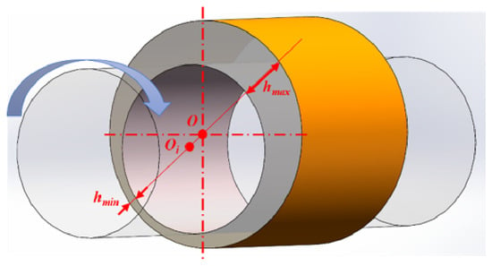
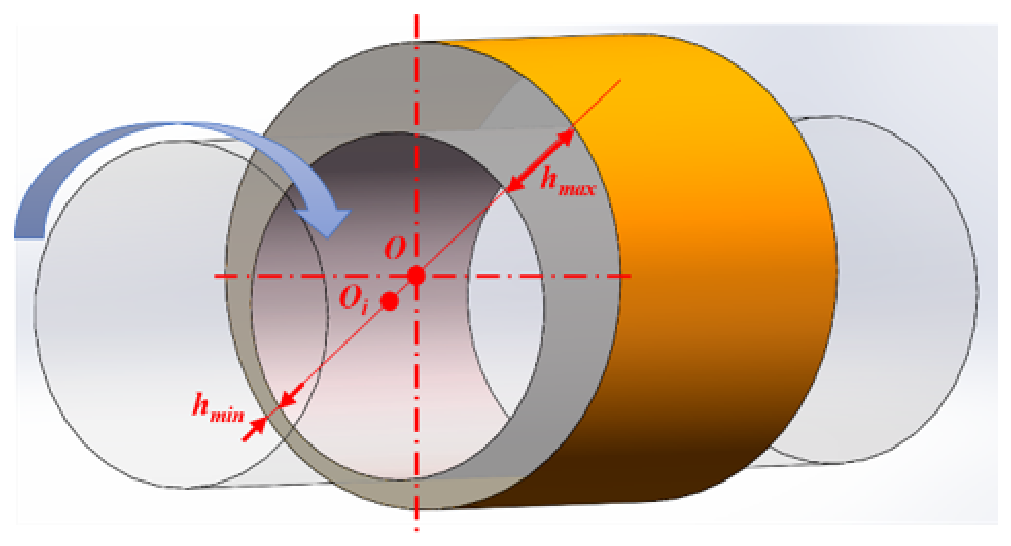
Figure 1 illustrates the lubrication mechanism of a cylindrical journal bearing. Under an external load F, the journal center is displaced relative to the bearing center O, resulting in an eccentric operating condition and a nonuniform lubricant film. Along the extended line connecting the two centers, the maximum film thickness and minimum film thickness occur on opposite sides of the bearing. Here, c represents the radial clearance, while R and r denote the bearing and journal radii, respectively.
Figure 1.
Schematic illustration of the converging and diverging lubricant film regions in a cylindrical journal bearing.
In the direction of journal rotation, the circumferential region extending from to forms a converging wedge, where the film thickness progressively decreases. This converging geometry, combined with the relative motion between the journal and bearing surfaces, generates hydrodynamic pressure and enables the lubricant film to support the external load. Conversely, the region extending from to forms a diverging wedge, where the increasing film thickness leads to a reduction in hydrodynamic pressure.
For oil-lubricated bearings, the lubricant film may undergo cavitation in the diverging region because the liquid cannot sustain substantial tensile stresses. Consequently, the effective pressure-generating region is generally confined to approximately half of the bearing circumference, although its actual extent depends on the operating conditions and cavitation boundaries.
2.2. Fluid Finite Element Calculation Theory
2.2.1. Governing Equations of Computational Fluid Dynamics
Under the continuum assumption, lubricating oil flow within the clearance of a plain bearing is governed by the mass and momentum conservation equations. When the oil-film temperature rise and the temperature dependence of viscosity are considered, the energy conservation equation must also be solved. In this study, the lubricating oil is treated as a Newtonian fluid, and the governing equations of the oil-film flow field are established based on the actual operating conditions.
The flow of lubricating oil satisfies the law of mass conservation. For an incompressible fluid, the continuity equation is expressed as
Under steady-state conditions, neglecting body forces, the momentum conservation equations for the lubricating oil-film flow field can be written as
For a Newtonian fluid, the viscous stress tensor is related to the velocity gradient as
The temperature distribution within the oil film is governed by the energy conservation equation. According to the first law of thermodynamics, the energy variation of a fluid element is mainly determined by convective heat transfer, heat conduction, and viscous dissipation. Under steady-state conditions, the energy conservation equation can be expressed as
2.2.2. Assumptions of the Computational Model
During shafting operation, the rotating journal draws lubricant into the wedge-shaped clearance between the journal and the bearing bush. Hydrodynamic action then generates a load-carrying oil film. The oil-film pressure balances the external load and separates the journal from the bearing bush, thereby establishing hydrodynamic lubrication. To develop a steady-state flow-field model for the plain journal bearing while reducing computational complexity, the following assumptions are introduced:
- The lubricant velocity is much lower than the local speed of sound. Therefore, the lubricant is treated as an incompressible fluid. The bearing operates under stable working conditions, and the oil-film flow is assumed to be three-dimensional, steady, and laminar.
- Body forces, such as gravity, are negligible compared with the pressure and viscous forces and are therefore ignored. Although fluid inertia is generally small under the thin-film lubrication assumption, the inertial terms are retained in the three-dimensional Navier–Stokes equations.
- The no-slip boundary condition is imposed on both the journal and bearing bush surfaces. Therefore, the lubricant velocity at each solid boundary is equal to the velocity of the corresponding wall.
- Thermal and elastic deformations of the journal, bearing bush, and bearing housing are neglected. All solid boundaries are treated as rigid surfaces, and contact between surface asperities is not considered.
- The lubricant density, specific heat capacity at constant pressure, and thermal conductivity are assumed to be constant. The dynamic viscosity varies with the local oil-film temperature to account for the viscosity–temperature coupling between the flow and temperature fields.
- The half-Sommerfeld boundary condition is adopted to simplify the treatment of the oil-film rupture region. The negative gauge pressure in the diverging wedge is set to zero. Therefore, only the oil-film pressure generated in the converging wedge is considered in the calculation of the bearing load-carrying capacity.
2.2.3. Boundary Conditions, Mesh Independence and Validation
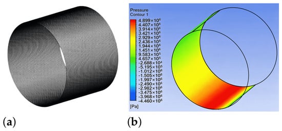
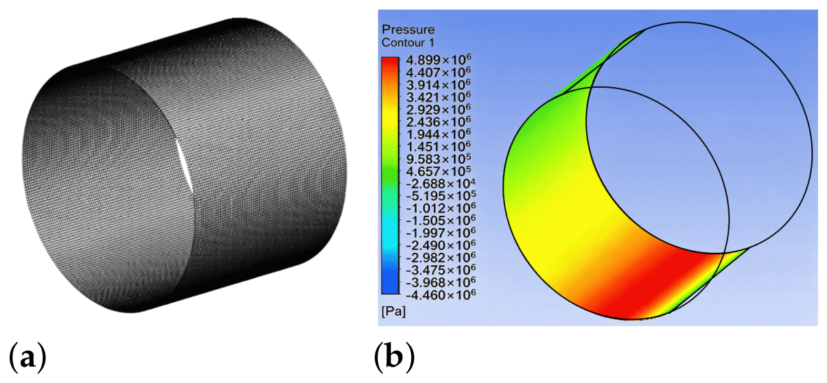
The fluid film is a thin annular gap between the rotating journal and the bearing sleeve, and it is discretised with a structured hexahedral mesh, with three cell layers across the film thickness to maintain mesh quality at the minimum film thickness (Figure 2a). The journal surface is specified as a no-slip moving wall rotating at the shaft speed, while the bearing sleeve and two axial ends are set as stationary no-slip walls. The three-dimensional steady laminar flow is solved with the pressure-based solver using the SIMPLE algorithm, with second-order discretisation for pressure and momentum. Convergence is judged by continuity and momentum residuals falling below (momentum below ) and by the monitored load capacity and maximum film pressure remaining stable (variation below 0.1 %). The calculated pressure field at the representative operating condition T = 45 °C, n = 117 r/min and = 0.22 mm is shown in Figure 2b.
Figure 2.
CFD model of the intermediate bearing oil film: (a) structured hexahedral mesh and (b) pressure distribution on the oil-film inner surface at °C, and .
2.3. BP Neural Network Model
A BP (back-propagation) neural network is a multilayer feed-forward network trained by error back-propagation [30]. For a network with a single hidden layer, the input–hidden and hidden–output weight matrices are denoted by and , respectively, while and represent the corresponding biases. The kth network output is expressed as
where m, n, and q denote the numbers of input, hidden, and output neurons, respectively; is the ith input; and and are the hidden-layer and output-layer activation functions, respectively.
The network is trained by minimising the sum of squared errors between the predicted outputs and the target values :
The prediction error is back-propagated to update the weights and biases iteratively. The input and target data are normalised to before training, and the predicted outputs are subsequently denormalised to their original scales.
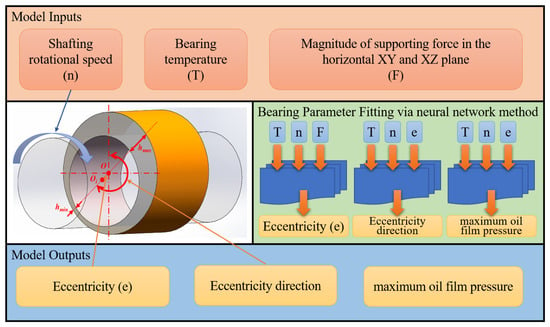
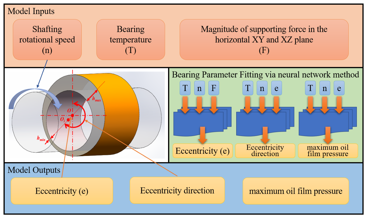
For each bearing class, three single-output networks were trained to predict the journal eccentricity e, attitude angle , and maximum film pressure . The inputs comprise the lubricant temperature T, shaft rotational speed n, and in-plane support force F for the oil-lubricated bearings, whereas only n and F are used for the water-lubricated stern bearings, with T omitted. The same network is applied to both the horizontal () and vertical () planes using the corresponding in-plane support force.
The training datasets were generated from the CFD parametric studies described in Section 3.2.1. For the intermediate and stern bearings, the investigated ranges were –60 °C, –, and –. For the bracket bearing, the corresponding ranges were –60 °C, –, and –. The resulting datasets comprised 1392, 696, and 1320 samples for the intermediate, stern, and bracket bearings, respectively.
The BP neural networks were developed using the MATLAB Neural Net Fitting toolbox, with a single hidden layer employing sigmoid activation functions and a linear output layer. The number of hidden neurons was optimised separately for each network by varying the hidden-layer size from 10 to 200 neurons and selecting the configuration that minimised the validation mean squared error (MSE).
The networks were trained using the Levenberg–Marquardt optimisation algorithm with an initial damping parameter of . Both inputs and targets were normalised to using the mapminmax function. The datasets were randomly divided into training, validation, and test subsets at a ratio of 70%/15%/15%. The maximum number of training epochs was set to 1000, with the default early-stopping criterion applied. The sample allocation and predictive performance of the nine BP surrogate models, evaluated using the coefficient of determination () and normalised root-mean-square error (RMSE), are summarised in Table 1.
Table 1.
Test-set accuracy of the BP surrogate models.
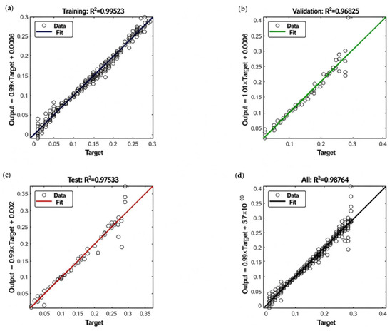
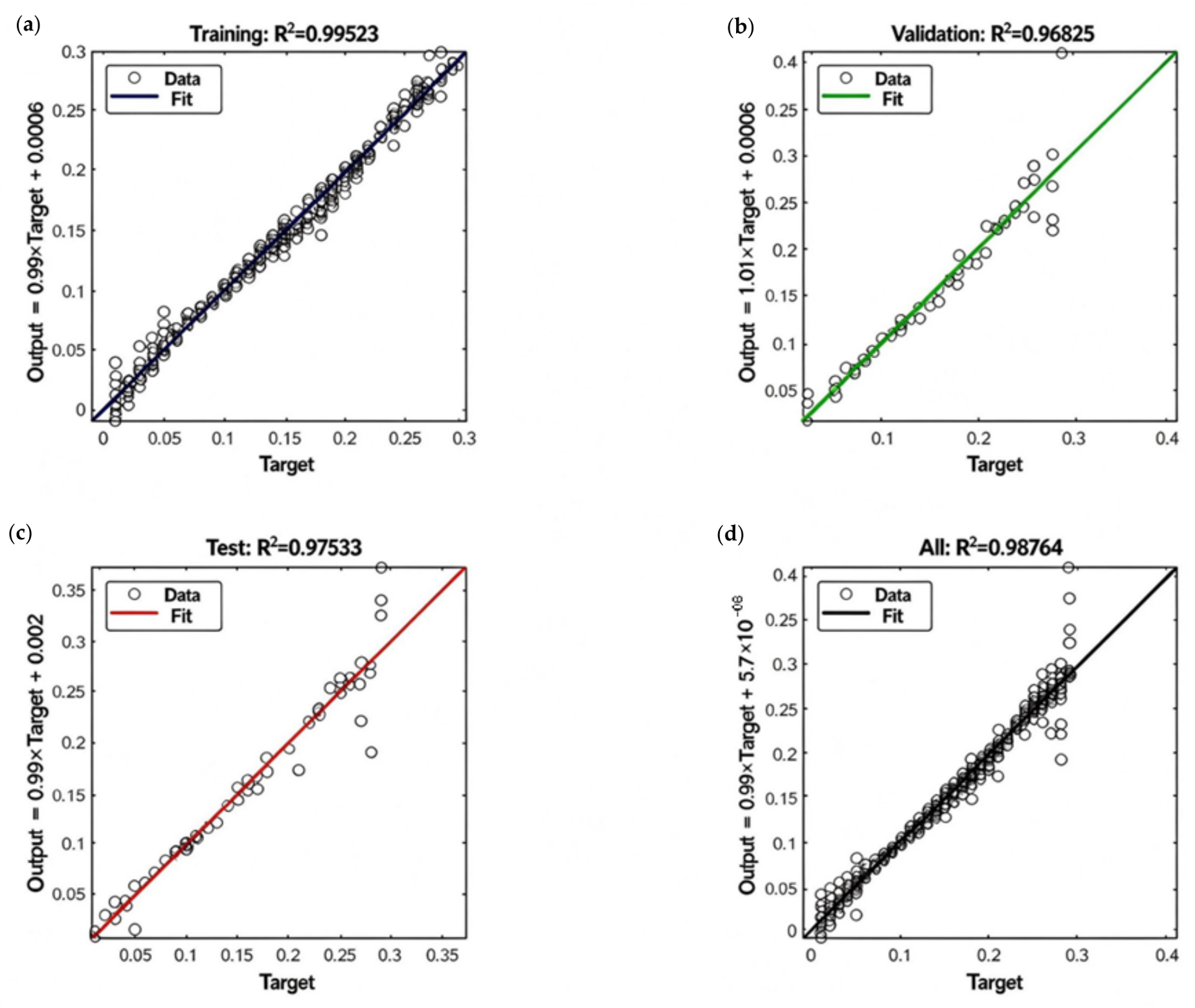
As shown in Table 1, the nine BP surrogate models achieved test-set values ranging from 0.908 to 0.977, with a mean of 0.952, and normalised RMSE values ranging from 0.0125 to 0.0281, with a mean of 0.0187. Figure 3 illustrates the agreement between CFD reference values and neural network predictions for the intermediate-bearing eccentricity model as a representative example. The predicted values are generally distributed close to the line of perfect agreement, indicating good predictive consistency. For this model, the test-set and normalised RMSE were 0.951 and 0.0206, respectively.
Figure 3.
Regression plots of the BP neural network predictions against CFD reference values for intermediate-bearing eccentricity: (a) training; (b) validation; (c) testing; and (d) all datasets.
2.4. Quantification of Hull Deformation and Acceleration
2.4.1. Quantification of Hull Deformation
The hogging and sagging deformation of the hull results from the combined effects of the still-water bending moment and the wave-induced bending moment. Accordingly, the longitudinal hull deformation is quantified by superimposing a quadratic parabolic model and a sinusoidal model:
The transverse bending deformation of the hull is represented using a quadratic parabolic distribution:
2.4.2. Quantification of Hull Acceleration
The hull is treated as a rigid body. The longitudinal acceleration results from the combined effects of pitch angular acceleration and heave acceleration. For conventional operating conditions, such as constant-speed or variable-speed navigation and small-rudder-angle maneuvering, the linear superposition method is adopted. For emergency or impact conditions, an amplification factor is introduced. The superimposed longitudinal acceleration is formulated as Equation (9).
The transverse acceleration is quantified using the same procedure as that adopted for the longitudinal acceleration.
3. Research Object and the Quasi-Static Modeling
The values and sources of all coefficients used in the hull-deformation and acceleration models are detailed in the Supplementary Materials, which also provide the complete quantification of hull deformation and ship-motion accelerations, the mapping of sea-state level, wave direction, loading and maneuvering conditions to specific translational and angular acceleration values, and the damage mechanisms and assessment criteria of the journal bearings.
3.1. Research Object
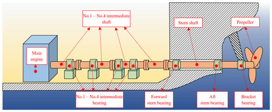
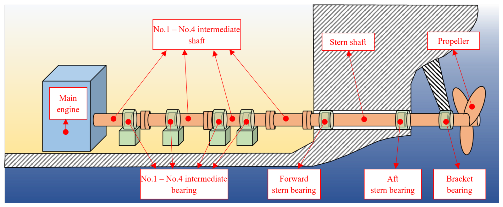
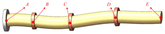
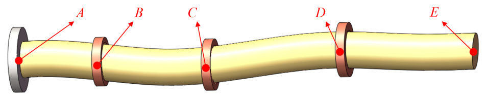
The multi-supported ultra-long shafting model developed in this study is based on the design data of an actual ship. The shafting has a total length of 57,329 mm and consists of four intermediate shafts and one stern shaft. The bearing arrangement is consistent with the actual ship design and includes four intermediate bearings, two stern bearings, and one bracket bearing. A schematic diagram of the shafting structure is shown in Figure 4.
Figure 4.
Schematic diagram of shafting structure.
All shaft segments are made of 40CrNiMoA alloy structural steel. The material has a density of , an elastic modulus of , a Poisson’s ratio of 0.3, a minimum tensile strength of , and a minimum yield strength of .
The geometric parameters of each shaft segment are listed in Table 2, and the parameters of each bearing are presented in Table 3. Melina S30 lubricating oil is used for the oil-lubricated bearings, and its main properties are given in Table 4. The forward and aft stern bearings are lubricated with seawater, with a density of and a dynamic viscosity of , which is assumed to remain constant; the water-film CFD model adopts the same boundary conditions and numerical solver settings as the oil-film model, without solving the temperature field.
Table 2.
Parameters of each shaft segment.
Table 3.
Bearing parameters.
Table 4.
Main properties of Melina S30 lubricating oil.
3.2. Quasi-Static Modeling of Multi-Point-Supported Ultra-Long Shafting
3.2.1. Modeling Methodology and Fundamental Principles
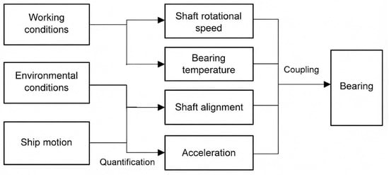
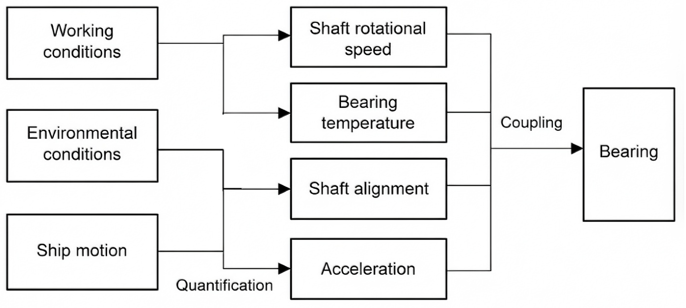
During ship operation, the operational loads, environmental loads, and ship-motion conditions vary continuously, as illustrated in Figure 5.
Figure 5.
Influence of operational loads, environmental loads and navigation motion states on shafting.
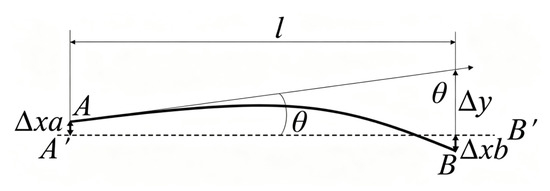
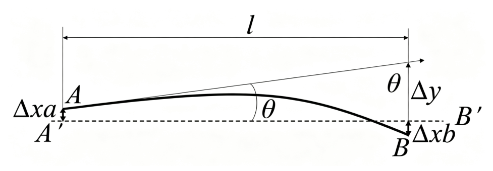
Bearing misalignment caused by hull deformation induces additional bending of the shaft and consequently generates additional bearing loads. The shafting is divided into individual shaft segments at the bearing locations. For the shaft segment shown in Figure 6, its length is denoted by ℓ. The theoretical shaft centerline is , whereas the actual shaft centerline is . At end A, the bearing displacement in the considered plane is , and the shaft forms an angle with the theoretical centerline. The bearing displacement at end B is .
Figure 6.
A shaft segment split at the bearing position.
Because end A has a displacement of relative to the theoretical shaft centerline and an angular deviation of , the effective displacement difference between ends A and B is expressed as
Combined with the equivalent stiffness of each shaft segment obtained from numerical simulation, the corresponding shear force can be calculated. The rotation angle of end B relative to the theoretical shaft centerline can also be determined using the angular deflection coefficient of the shaft segment.
As shown in Figure 7, the shaft segment is fixed at end A, which represents the main-engine end. The shear forces in the individual shaft segments are expressed as
Figure 7.
Bending schematic diagram of shafting in a certain plane.
Accordingly, the bearing forces can be obtained from the differences between the shear forces of adjacent shaft segments:
In this study, a quasi-static approach is adopted to analyse the shafting system. Under each prescribed operating condition, the shafting is assumed to be in static equilibrium, and the shaft deflections and bearing support forces are determined by solving the corresponding equilibrium equations. The inertial effects induced by the ship’s translational and angular motions are represented by equivalent static loads derived from the corresponding acceleration coefficients and applied together with gravitational loads, while hull deformation is incorporated through prescribed displacement boundary conditions. Accordingly, the model neglects damping and time-dependent dynamic responses, requiring no time integration. This approach is considered appropriate for operating conditions that vary slowly relative to the natural periods of the shafting system, as the primary objective is to evaluate the equilibrium configuration and bearing load distribution rather than transient vibration or impact responses.
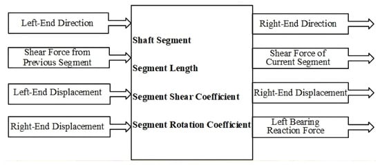
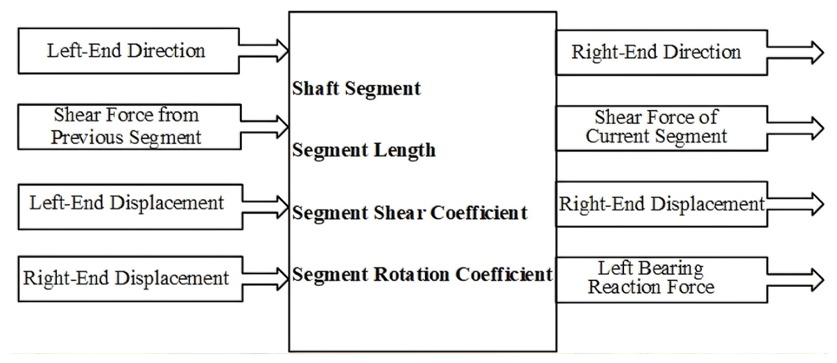
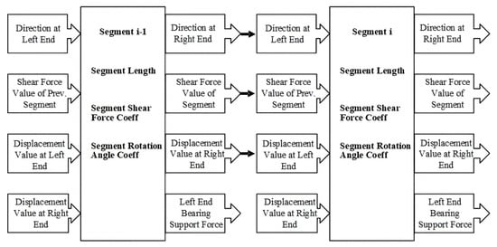
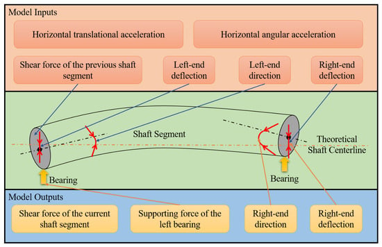
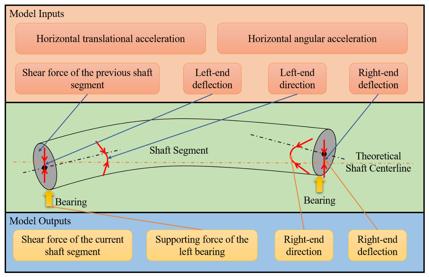
The bearing support forces are determined through a sequential shear-force analysis of the shaft segments. As illustrated in Figure 8, the calculation for each segment takes the shaft inclination at the left end, the deflections at both ends, and the shear force transmitted from the preceding segment as inputs. Using the segment length, equivalent stiffness, and angular deflection coefficient, the shaft inclination at the right end, the shear force within the current segment, and the support reaction at the left bearing are determined. The right-end deflection is subsequently transferred to the next segment, allowing the calculation to proceed sequentially along the shafting system.
Figure 8.
Schematic diagram for bending calculation of a single shaft segment in a certain plane.
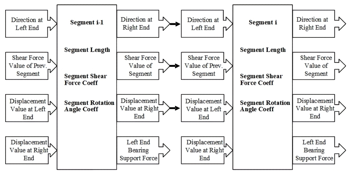
The above describes the calculation of bending deformation for a single shaft segment in a specific plane. When multiple shaft segments are connected as shown in Figure 9, the direction, deflection value and shear force value output from the right end of the previous segment are taken as the inputs for the current one.
Figure 9.
Schematic diagram for bending calculation of multi-segment shaft in a certain plane.
The above describes the modeling idea for the influence of bending deformation of multi-segment shafting on the supporting force of each bearing in a single plane. In three-dimensional space, calculations only need to be conducted separately on the horizontal XY plane and vertical XZ plane. The magnitude and direction of additional supporting forces exerted on each bearing by shaft bending deformation can then be solved via vector superposition and trigonometric calculations.
The supporting forces generated on each bearing by gravity and accelerations induced by environmental loads and ship navigation motions can be obtained by multiplying the translational acceleration coefficient and angular acceleration coefficient of each bearing (derived from simulation results) with translational acceleration and angular acceleration, respectively. The vector sum of supporting forces caused by shaft bending deformation, gravity and acceleration yields the total magnitude and direction of the supporting force acting on the bearing under the given operating condition.
Prior to establishing the quasi-static shafting model in Simulink, Fluent is employed to simulate the oil-film flow field of the bearings under varying lubricant temperatures, journal eccentricities, and rotational speeds. The oil-film pressure distribution is obtained, and the bearing support force and maximum oil-film pressure are calculated by integrating the positive pressure distribution and identifying its maximum value, respectively. A dataset is then constructed from the operating parameters and corresponding CFD results, and the MATLAB R2022A Neural Net Fitting toolbox is used to develop surrogate models for the nonlinear bearing support characteristics. After training and validation, the neural networks are implemented as Simulink modules and integrated into the quasi-static shafting model to enable efficient prediction of bearing support forces and maximum oil-film pressures. The journal eccentricity and attitude angle are determined from the displacement components of the journal relative to the bearing centre.
3.2.2. Modelling Procedure for the Investigated Shafting System
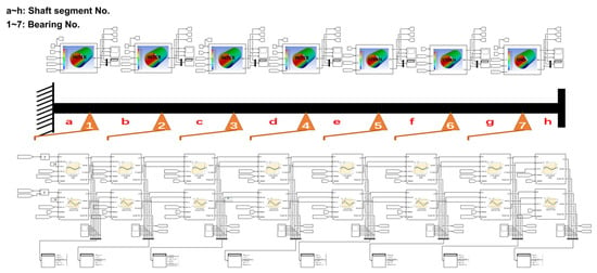
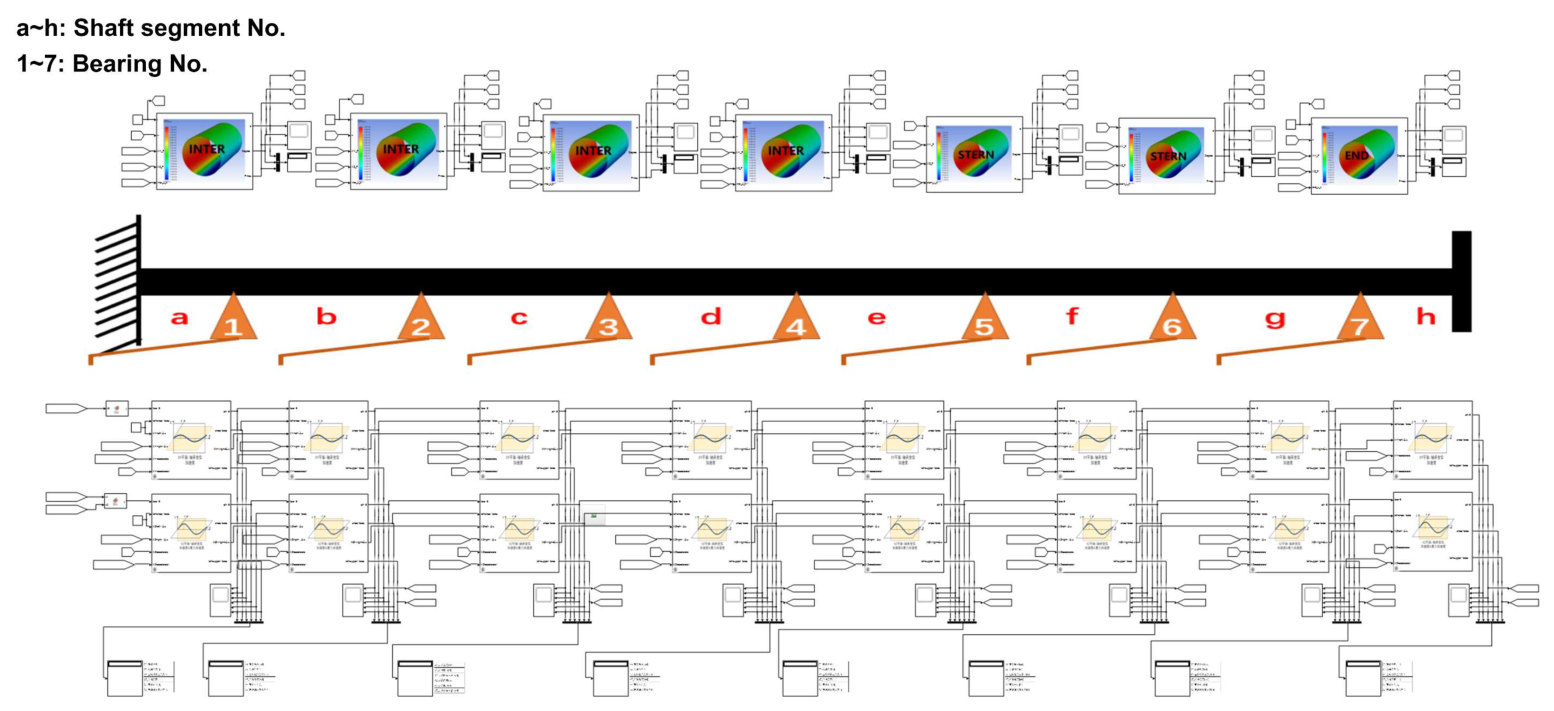
The overall quasi-static model of the investigated shafting system is illustrated in Figure 10. Based on the analysis presented in Section 3.2.1, each shaft segment is modelled separately in the horizontal (XY) and vertical (XZ) planes. The modelling procedure for the horizontal plane is illustrated in Figure 11, and the same approach is applied to the vertical plane.
Figure 10.
Overall model of the research object.
Figure 11.
Sub-model of shaft segment on the horizontal plane.
The model contains six inputs: the rotation angle at the left end of the shaft segment, the shear force transmitted from the preceding shaft segment, the deflections at the left and right ends, the horizontal translational acceleration, and the lateral angular acceleration. The model has four outputs: the rotation angle at the right end, the shear force of the current shaft segment, the deflection at the right end, and the supporting force of the left bearing. In addition, five constant parameters are required, including the shaft-segment length, equivalent stiffness, angular deflection coefficient, translational acceleration coefficient, and lateral angular acceleration coefficient.
Before constructing the Simulink model, the bending deformation of each shaft segment is calculated using finite element analysis. The results show an approximately linear relationship between the bending deflection and the applied concentrated load. Therefore, the ratio of the concentrated load to the end deflection is defined as the equivalent stiffness of the shaft segment. The ratio of the end rotation angle to the end deflection is defined as the angular deflection coefficient. The equivalent stiffness and angular deflection coefficient of each shaft segment are listed in Table 5.
Table 5.
Coefficients obtained by simulation for each shaft segment.
Meanwhile, the finite element method is also used to calculate the bearing supporting forces of the shafting under different accelerations. It is found that there is a strong linear relationship between the magnitude of each bearing’s supporting force and the acceleration. The ratio of each bearing’s supporting force to the translational acceleration is defined as the translational acceleration coefficient, and the ratio of each bearing’s supporting force to the longitudinal angular acceleration is defined as the longitudinal angular acceleration coefficient. The values of these coefficients are listed in Table 6.
Table 6.
Bearing load coefficients for translational and angular accelerations.
For each shaft segment, simply copy the above submodel, modify the corresponding parameters, and connect all inter-faces properly according to the number of shaft segments of the research object.
The intermediate-bearing submodel is illustrated in Figure 12. The model has four inputs: shaft rotational speed, bearing temperature, and bearing support forces in the horizontal (XY) and vertical (XZ) planes. The temperature input is omitted for the water-lubricated stern bearings. The model provides three outputs: journal eccentricity, attitude angle, and maximum film pressure. It should be noted that the present bearing model assumes that the journal axis remains parallel to the bearing-bore axis. Consequently, relative angular misalignment and its effects on the film thickness and pressure distribution are not considered. Incorporating these effects into the bearing model represents a potential direction for future research.
Figure 12.
Sub-model of the intermediate bearing.
3.2.3. Calculation of Bearing Positions Based on Shaft Alignment Principles
Shaft alignment is essential for the safe and reliable operation of marine propulsion systems. For long shafting systems, the rational alignment method is commonly adopted. Therefore, the initial position of each bearing after alignment must be determined. First, the finite element method is used to calculate the bending deformation of each intermediate shaft supported by the bearings and temporary supports. The alignment calculation is then performed sequentially from the main-engine end to the stern shaft according to the theoretical GAP and SAG values of adjacent shaft segments. The calculated initial positions of the bearings after alignment are listed in Table 7.
Table 7.
Initial bearing positions after rational alignment (mm).
3.3. Model Inputs
The longitudinal hull deformation is first quantified relative to the bow and stern reference points. The resulting displacement values are then transformed to a reference system based on the main-engine crankshaft output flange, as listed in Table 8.
Table 8.
Longitudinal deflections of the bearings.
Longitudinal hull deformation also induces a rotation of the main-engine crankshaft output flange, which must be incorporated into the shafting model. To account for the simplification and uncertainty of the hull deformation model, a random perturbation of 5% is introduced.
The transverse hull deformation is quantified based on the maximum allowable deformation specified by the rules of the China Classification Society (CCS). The corresponding transverse deflections at the bearing locations are presented in Table 9.
Table 9.
Transverse deflections of the bearings.
Similarly, transverse hull deformation changes the rotation angle of the main-engine crankshaft output flange. This angular variation is also included in the shafting model.
4. Results and Discussion
4.1. Effects of Hull Deformation on Bearing Performance
4.1.1. Operating Conditions of the Bearings Under Longitudinal Hull Deformation
To investigate the effects of longitudinal hull deformation on the load distribution and operating conditions of the multi-support bearings, a series of single-factor cases is established. The longitudinal hull deformation coefficients are set to , while the transverse hull deformation, longitudinal acceleration, and transverse acceleration are set to zero. The shaft rotational speed is maintained at the rated value, and the temperature of each bearing is set to its design value. Under these conditions, the specific pressure, value, and maximum specific pressure of each bearing are calculated. The results are shown in Figure 13.
Figure 13.
Effects of longitudinal hull deformation on the normalized performance indicators of each bearing: (a) ratio of specific pressure to the allowable value; (b) ratio of value to the allowable value; and (c) ratio of maximum specific pressure to the allowable value.
Figure 13 shows the effects of longitudinal hull deformation on the operating indicators of each bearing. The ratios of the specific pressure and maximum specific pressure to their allowable values remain relatively low for all bearings. This indicates that the bearings retain sufficient load-carrying margins.
Compared with the baseline condition, longitudinal hull deformation changes the specific pressure of each bearing by to . This result indicates that hull deformation modifies the bending configuration of the shafting and causes load redistribution among the bearings. The specific pressures of adjacent bearings exhibit alternating increases and decreases. Therefore, bearings at different positions respond differently to longitudinal hull deformation. Because the shaft rotational speed remains constant, the value is mainly governed by the specific pressure and shows a similar variation trend.
Overall, none of the bearing indicators exceed their allowable limits within the specified range of longitudinal hull deformation. However, the uniformity of the bearing load distribution is reduced to some extent.
4.1.2. Operating Conditions of the Bearings Under Transverse Hull Deformation
To investigate the effects of transverse hull deformation on the load distribution and operating conditions of the multi-support bearings, a series of single-factor simulation cases is established. The transverse hull deformation coefficient is set to . The longitudinal hull deformation, longitudinal acceleration, and transverse acceleration are set to zero. The shaft rotational speed and bearing temperature are maintained at the rated and design values, respectively.
Under these conditions, the specific pressure, value, and maximum specific pressure of each bearing are calculated. The results are shown in Figure 14.
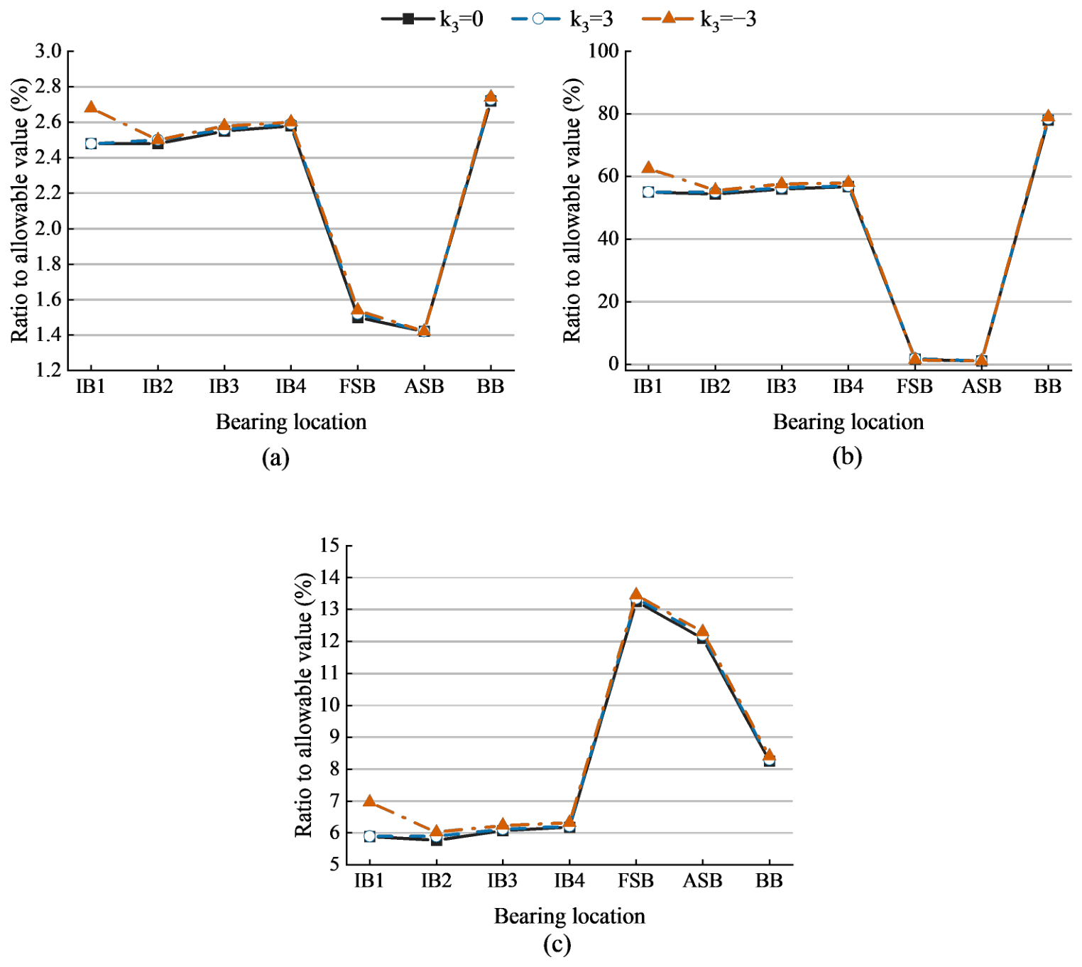
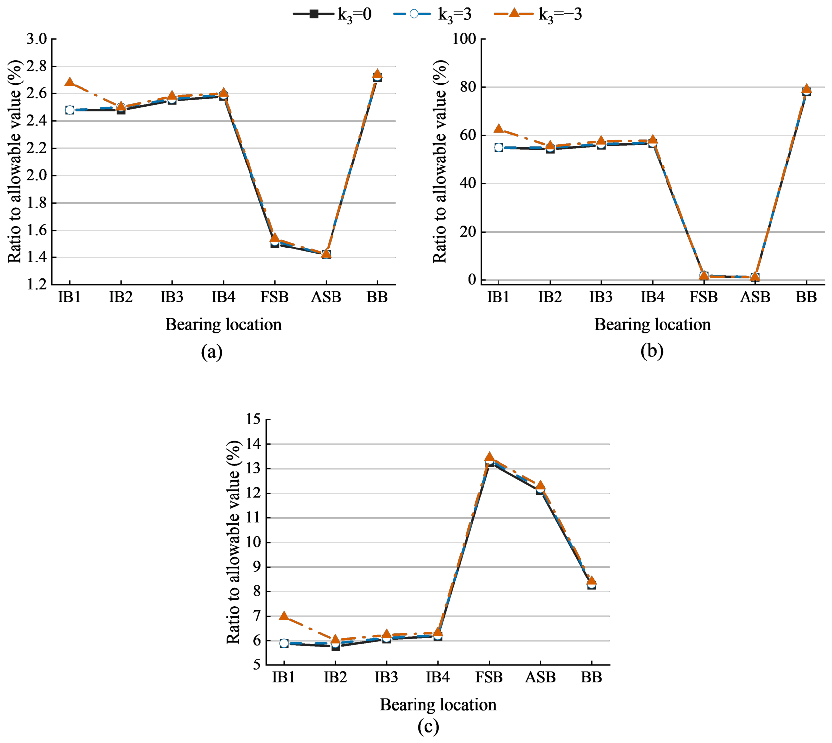
Figure 14.
Effects of transverse hull deformation on the normalized performance indicators of each bearing: (a) ratio of specific pressure to the allowable value; (b) ratio of value to the allowable value; and (c) ratio of maximum specific pressure to the allowable value.
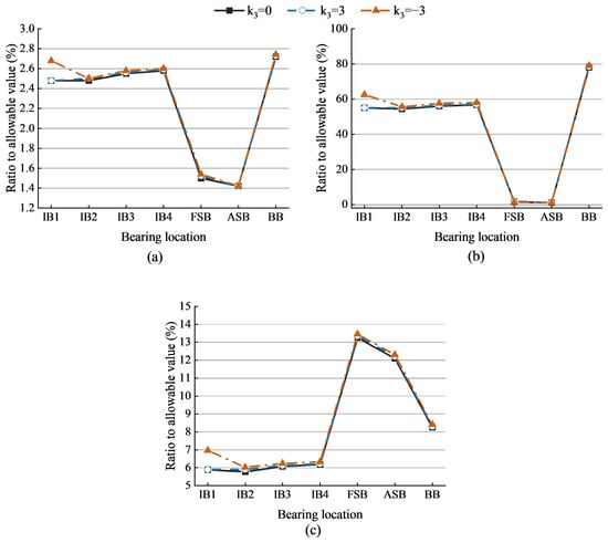
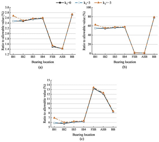
Figure 14 shows the effects of transverse hull deformation on the operating indicators of each bearing. The ratios of the specific pressure and maximum specific pressure to their allowable values remain relatively low for all bearings. This indicates that sufficient load-carrying margins are maintained within the specified range of transverse hull deformation.
Compared with the baseline condition (), the specific pressure of each bearing changes by to , and most bearings exhibit an increase in specific pressure. This result indicates that transverse hull deformation changes the relative position between the journals and bearings and consequently causes bearing load redistribution. Since the shaft rotational speed remains constant, the value is mainly governed by the specific pressure and shows a similar variation trend.
Overall, transverse hull deformation does not cause the specific pressure or maximum specific pressure of any bearing to exceed its allowable limit. However, it increases the degree of load concentration in some bearings.
4.2. Effects of Ship Acceleration on Bearing Performance
4.2.1. Operating Conditions of the Bearings Under Longitudinal Acceleration
To investigate the effects of longitudinal ship acceleration on the load distribution and operating conditions of the multi-support bearings, a series of single-factor simulation cases is established. The sea states range from Level 3 to Level 8. The wave conditions include head seas and other wave directions. The maneuvering conditions include variable-speed navigation and large-rudder-angle turning, while the loading conditions include full load and light load.
Both upward and downward longitudinal translational accelerations and longitudinal angular accelerations are considered. The longitudinal and transverse hull deformations and the transverse acceleration are set to zero. The shaft rotational speed and bearing temperatures are maintained at the rated speed and design values, respectively.
Under these conditions, the specific pressure, value, and maximum specific pressure of each bearing are calculated, and the results are presented in Table 10 and Table 11. The results show that longitudinal translational and angular accelerations jointly modify the equivalent inertial load of the shafting, thereby causing load redistribution among the bearings.
Table 10.
Representative operating conditions under longitudinal acceleration.
Table 11.
Ratios of bearing performance indicators to their allowable values for selected cases of longitudinal acceleration (%).
When both translational and angular accelerations act upward, the bearing loads exhibit different variation trends. Under some operating conditions, the translational inertial force acts against gravity and reduces the bearing loads. Under other conditions, the additional inertial load induced by angular acceleration is distributed non-uniformly along the shafting. This increases the loads of the stern-side bearings and aggravates the non-uniform load distribution among the bearings.
Further comparison of different acceleration-direction combinations shows that the overall bearing loads increase when the translational acceleration acts upward and the angular acceleration acts downward. In contrast, the bearing loads decrease when the translational acceleration acts downward and the angular acceleration acts upward. These results indicate that angular acceleration has a more pronounced effect on bearing load redistribution under the investigated operating conditions.
To quantify the respective contributions of translational and angular accelerations, the maximum longitudinal translational acceleration of and the maximum longitudinal angular acceleration of are selected. Combined with the acceleration coefficients of the bearings obtained in Section 2, the additional bearing loads induced by the two inertial excitations are calculated. The results are listed in Table 12.
Table 12.
Additional bearing loads and their ratios under longitudinal translational and angular accelerations.
Table 12 further shows that, within the investigated operating range, the additional bearing load induced by longitudinal angular acceleration is approximately 6–11 times that induced by longitudinal translational acceleration. This result indicates that angular acceleration is the dominant inertial factor affecting bearing load redistribution. When both accelerations act downward, the corresponding inertial loads act in the same direction as gravity. Their combined effect causes a marked increase in bearing loads and raises the risk of local overload and lubrication deterioration.
Pearson correlation analysis was conducted using 5000 longitudinal-acceleration cases, 4000 transverse-acceleration cases, and 10,000 combined operating cases to assess the relationships between operating factors and bearing performance indicators. Sea-state levels were represented numerically (3–8), while wave direction, loading condition, and maneuvering condition were numerically encoded. Under longitudinal acceleration, sea-state level exhibited the strongest average correlation (), followed by loading condition (), wave direction (), and maneuvering condition (). In contrast, shaft rotational speed showed a negligible correlation (). Although all reported correlations were statistically significant (two-tailed ), the rotational-speed correlation had negligible practical significance (). These findings identify sea state, loading condition, and wave direction as the factors most strongly associated with bearing performance under longitudinal acceleration.
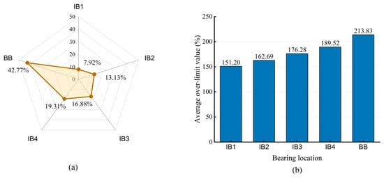
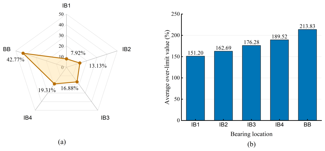
Under several operating conditions, the ratio of the value to its allowable limit exceeds 100%, indicating a potential risk of bearing scuffing. Statistical analysis shows that the exceedances occur mainly in the intermediate bearings and the bracket bearing. The exceedance frequency and mean exceedance magnitude of each bearing are shown in Figure 15.
Figure 15.
Statistical characteristics of -value exceedances for each bearing: (a) proportion of exceedance occurrences and (b) mean ratio of the value to its allowable limit under exceedance conditions.
Figure 15 presents the statistical characteristics of -value exceedances for different bearings and operating factors. The exceedances occur mainly in the intermediate bearings and the bracket bearing. Among them, the bracket bearing exhibits both the highest exceedance frequency and the largest mean ratio of the value to its allowable limit. In contrast, the No. 1 intermediate bearing shows the lowest exceedance frequency and the smallest mean exceedance ratio. These results indicate clear differences in lubrication-failure risk among bearings at different support positions.
With respect to the acceleration-direction combinations, the highest proportion of -value exceedances, 52.74%, occurs when both the longitudinal translational acceleration and longitudinal angular acceleration act downward. Under this condition, the corresponding inertial loads act in the same direction as gravity. Their combined effect increases the bearing loads and frictional power density, thereby increasing the probability of the value exceeding its allowable limit. This result is consistent with the preceding analysis of the effects of longitudinal acceleration on bearing load distribution.
As the sea state increases from Level 3 to Level 8, the proportions of -value exceedances increase from 0.56% to 3.34%, 9.28%, 17.48%, 27.51%, and 41.83%, respectively. This clear upward trend indicates that intensified ship-motion excitation under severe sea conditions accelerates the deterioration of bearing lubrication performance. Among the investigated wave directions, head seas produce the highest exceedance proportion of 74.23% and a mean -to-allowable-limit ratio of 198.52% under exceedance conditions. This indicates that the longitudinal inertial excitation induced by head seas has the most adverse effect on bearing characteristics.
At the maximum shaft rotational speed of , the proportion of -value exceedances reaches 48.23%, while the mean -to-allowable-limit ratio reaches 209.62%. Because the value depends jointly on specific pressure and sliding velocity, an increase in rotational speed directly raises the frictional power density and consequently increases the risk of bearing scuffing. By contrast, the exceedance proportions under different maneuvering and loading conditions remain close to 50% and show relatively small differences among the individual categories. This suggests that, within the investigated sample range, maneuvering condition and loading condition have less influence on the occurrence of -value exceedances than sea state, wave direction, and rotational speed.
4.2.2. Operating Conditions of the Bearings Under Transverse Acceleration
To investigate the effects of transverse ship acceleration on the load distribution and operating conditions of the multi-support bearings, a series of single-factor simulation cases is established. The sea states range from Level 3 to Level 8. The wave directions include beam seas, head or following seas, and oblique seas. The maneuvering conditions include small- and large-rudder-angle turning, while the loading conditions include full load and light load. Both positive and negative transverse translational accelerations are considered.
The longitudinal and transverse hull deformations and the longitudinal acceleration are set to zero. The shaft rotational speed and bearing temperatures are maintained at the rated speed and design values, respectively. Under these conditions, the specific pressure, value, and maximum specific pressure of each bearing are calculated. The selected operating conditions and corresponding bearing performance indicators are presented in Table 13 and Table 14, respectively.
Table 13.
Representative operating conditions under transverse acceleration.
Table 14.
Ratios of bearing performance indicators to their allowable values for selected cases of transverse acceleration (%).
Correlation analysis under transverse-acceleration conditions shows that the sea-state level has an average correlation coefficient of 0.45 with the bearing performance indicators, indicating a moderate correlation. The average correlation coefficient of wave direction is 0.27, indicating a weak correlation. The coefficients of shaft rotational speed, loading condition, and maneuvering condition are all below 0.04. Their effects are therefore limited within the investigated sample range. These results indicate that sea state is the main factor affecting bearing performance under transverse acceleration, whereas wave direction has a secondary influence.
Further analysis of the -value exceedances shows that the ratio of the value to its allowable limit exceeds 100% only for the bracket bearing under a small number of operating conditions. This indicates a potential risk of scuffing failure at this bearing. The exceedance cases account for only 0.37% of all samples and occur exclusively at the bracket bearing. Therefore, the lubrication-failure risk under transverse acceleration is highly concentrated at this support position.
When the transverse acceleration acts to the left, 59.09% of the exceedance cases occur. However, the difference from the opposite direction is small. This indicates that the direction of transverse acceleration is not the dominant factor governing -value exceedance. All exceedance cases occur under extreme combined conditions, including a shaft rotational speed of , sea-state Level 8, large-rudder-angle turning, and beam seas. Therefore, the exceedance is mainly caused by the combined effects of severe sea-state excitation, high rotational speed, and an unfavorable wave direction. Under full-load conditions, the exceedance proportion is also 59.09%, with no marked difference from that under light-load conditions. This suggests that loading condition has a relatively limited effect on the -value exceedance of the bracket bearing.
4.3. Operating Conditions of the Bearings Under Combined Operating Conditions
The preceding analyses consider longitudinal hull deformation, transverse hull deformation, longitudinal acceleration, and transverse acceleration separately. Within the limits specified by CCS rules, hull deformation has a limited effect on bearing performance. However, excessive hull deformation caused by insufficient structural stiffness may significantly alter the bearing load distribution. In particular, longitudinal hull deformation produces alternating increases and decreases in the loads of adjacent bearings.
Longitudinal acceleration may either increase or decrease the bearing loads, depending on the directions of the translational and angular accelerations. Transverse acceleration generally increases the bearing loads. The effects of acceleration are mainly governed by sea state, wave direction, and maneuvering condition. The exceedance results are interpreted as an indicator-based risk assessment. In engineering practice, the value and the maximum specific pressure serve as screening indicators: an exceedance of the allowable limit indicates an elevated risk of scuffing (adhesive failure), and an exceedance of the allowable fatigue bearing pressure indicates an elevated risk of fatigue pitting. These correspondences are based on material engineering practice and the allowable values specified in the relevant standards. The degree of exceedance is used to quantify the risk level, with a larger ratio corresponding to a higher risk.
To investigate the combined effects of multiple operating factors on the load distribution and operating conditions of the multi-support bearings, combined simulation cases are established. The sea states range from Level 3 to Level 7. The wave directions include beam seas, head seas, following seas, and oblique seas. Both positive and negative longitudinal translational and angular accelerations are considered. The longitudinal hull deformation coefficients satisfy , while the transverse hull deformation coefficient satisfies .
The remaining operating conditions include variable-speed navigation, large-rudder-angle turning, full load, and rightward transverse acceleration. The shaft rotational speed and bearing temperatures are maintained at the rated speed and design values, respectively. Under these combined conditions, the specific pressure, value, and maximum specific pressure of each bearing are calculated. The selected operating conditions and corresponding results are presented in Table 15 and Table 16, respectively.
Table 15.
Representative combined operating conditions.
Table 16.
Ratios of selected bearing performance indicators to their allowable values under representative combined operating conditions (%).
Comprehensive analysis under multi-factor coupled conditions shows that the loads of adjacent bearings increase and decrease alternately under some operating conditions. This indicates that hull deformation and ship-motion-induced inertial loads change the shafting deflection profile and bearing reaction-force distribution, thereby causing load redistribution among the bearings.
Among the investigated factors, sea-state level is the dominant environmental factor affecting bearing loads, followed by wave direction. In comparison, the longitudinal and transverse hull deformation coefficients have relatively limited effects. Statistical analysis further shows that bearing-load exceedances occur mainly under severe sea conditions. Sea-state Levels 6 and 7 account for 60.43% of all exceedance cases, of which Level 7 contributes 32.86% and Level 6 contributes 27.57%. These proportions are considerably higher than those under lower sea states.
Regarding wave direction, head seas produce the highest bearing-load exceedance proportion of 33.98%, whereas the proportions under the other wave directions are relatively similar. Overall, the combination of sea-state Level 7 and head seas presents the highest risk of bearing-load exceedance.
Cases involving the exceedance of only one bearing account for the largest proportion, reaching 56.75%. The proportions involving simultaneous exceedances of two, three, and four bearings are 20.22%, 8.88%, and 6.81%, respectively. Among the multiple-bearing exceedance cases, the simultaneous exceedance of the No. 4 intermediate bearing and bracket bearing accounts for the highest proportion of 25.94%. This is followed by the combination of the No. 3 intermediate bearing and bracket bearing, which accounts for 19.69%. These results indicate that the bracket bearing and its adjacent intermediate bearings are more sensitive to multi-factor coupled loads. They should therefore receive particular attention in the load-safety assessment of ultra-long multi-support propulsion shafting.
5. Conclusions
1. A coupled quasi-static model of an ultra-long multi-support propulsion shafting system was developed by integrating hull deformation, ship-motion-induced inertial loads, shaft alignment, bearing support characteristics, CFD simulations, and a BP neural network surrogate model.
2. Hull deformation within the allowable range had a limited effect on bearing safety. Longitudinal deformation caused alternating load redistribution among adjacent bearings, whereas transverse deformation mainly affected the intermediate bearings.
3. Ship-motion acceleration was the dominant factor affecting bearing loads and lubrication performance. The load induced by longitudinal angular acceleration was approximately 6–11 times that induced by translational acceleration, and downward combined accelerations produced the highest -value exceedance risk.
4. Bearing performance limits were exceeded predominantly under severe sea states, particularly in head seas. The bracket bearing and adjacent intermediate bearings were most susceptible to exceeding the allowable limit, whereas the stern bearings exhibited the highest risk of excessive maximum specific pressure. These conditions may increase the susceptibility to scuffing and fatigue pitting, respectively, highlighting the need for prioritised condition monitoring at these bearing locations.
Supplementary Materials
The following supporting information can be downloaded at https://doi.org/10.6084/m9.figshare.32775465, accessed on 27 October 2026.
Author Contributions
Conceptualization, J.G. and H.Z.; methodology, J.G. and X.K.; software, J.G. and Z.C.; formal analysis, J.G. and X.K.; investigation, J.G., Z.C. and Q.Z.; data curation, J.G. and Z.C.; visualization, J.G. and Z.C.; validation, X.K., X.L. and Q.Z.; resources, X.L.; supervision, H.Z.; project administration, H.Z.; funding acquisition, H.Z.; writing—original draft preparation, J.G.; writing—review and editing, X.L. and Q.Z. All authors have read and agreed to the published version of the manuscript.
Funding
This work was supported by the National Natural Science Foundation of China (Grant No. U2341284) and the Fundamental Research Funds for the Central Universities (Grant No. 104972026YJS0019).
Data Availability Statement
The Supplementary Materials and data supporting the findings of this study are openly available in the Figshare repository at https://doi.org/10.6084/m9.figshare.32775465.
Conflicts of Interest
Author Quan Zou was employed by the company Wuhan Heavy Industry Casting and Forging Co., Ltd. The remaining authors declare that the research was conducted in the absence of any commercial or financial relationships that could be construed as a potential conflict of interest. The funders had no role in the design of the study; in the collection, analyses, or interpretation of data; in the writing of the manuscript; or in the decision to publish the results.
Nomenclature
| Center of the journal | |
| O | Center of the bearing |
| Maximum oil-film thickness | |
| Minimum oil-film thickness | |
| Lubricant density | |
| Fluid velocity vector | |
| Fluid velocity components in the x, y, and z directions | |
| p | Fluid pressure |
| Components of the viscous stress tensor | |
| T | Lubricant temperature |
| Activation function | |
| Viscous dissipation function | |
| Weight matrix from the input layer to the hidden layer | |
| Weight matrix from the hidden layer to the output layer | |
| Longitudinal hull deformation | |
| L | Ship length |
| x | Longitudinal coordinate along the hull |
| Hull deformation induced by the still-water bending moment | |
| Hull deformation induced by the wave-induced bending moment | |
| Wave-load combination factor | |
| Maximum midship deformation induced by the still-water bending moment | |
| Maximum midship deformation induced by the wave-induced bending moment | |
| Local longitudinal-stiffness correction coefficient | |
| Shafting–hull coupling correction coefficient | |
| Still-water bending deformation coefficient | |
| Wave-induced bending deformation coefficient | |
| Transverse hull deformation | |
| Local transverse-stiffness correction coefficient | |
| Maximum transverse deformation at midship | |
| Transverse hull-deformation coefficient | |
| Wave-direction coefficient | |
| Loading-condition coefficient | |
| Superimposed longitudinal hull acceleration | |
| Longitudinal acceleration induced by sea conditions | |
| Longitudinal acceleration induced by maneuvering | |
| Longitudinal-impact amplification factor | |
| Characteristic points of the shafting system | |
| Theoretical centerline of shaft segment | |
| Deflections of the shaft-segment ends relative to the theoretical centerline | |
| Inclination angle of the shaft segment relative to the theoretical centerline | |
| Effective relative deflection at end B | |
| ℓ | Length of the shaft segment |
| Bearing support reaction forces | |
| Shear forces in the corresponding shaft segments | |
| Longitudinal hull deflection at bearing i | |
| Transverse hull deflection at bearing i | |
| n | Shaft rotational speed (r/min) |
| F | Bearing force/load capacity |
| e | Eccentricity (mm) |
| Maximum specific pressure (MPa) | |
| Connection weight | |
| b | Bias |
| Hidden-layer activation function | |
| Output-layer activation function | |
| Levenberg–Marquardt damping parameter | |
| MSE | Mean squared error |
| Coefficient of determination | |
| RMSE | Root-mean-square error |
References
- Xiong, D.-L.; Wang, S.-H. Research on dynamic characteristic of marine shafting–oil film–stern structure system. J. Dyn. Syst. Meas. Control 2019, 141, 1–7. [Google Scholar] [CrossRef] [Scilit]
- Machado, T.H.; Alves, D.S.; Cavalca, K.L. Investigation about journal bearing wear effect on rotating system dynamic response in time domain. Tribol. Int. 2019, 129, 124–136. [Google Scholar] [CrossRef] [Scilit]
- Tala-Ighil, N.; Fillon, M. A numerical investigation of both thermal and texturing surface effects on the journal bearings static characteristics. Tribol. Int. 2015, 90, 228–239. [Google Scholar] [CrossRef] [Scilit]
- Sun, J.; Gui, C. Hydrodynamic lubrication analysis of journal bearing considering misalignment caused by shaft deformation. Tribol. Int. 2004, 37, 841–848. [Google Scholar] [CrossRef] [Scilit]
- Pennacchi, P.; Vania, A.; Chatterton, S. Nonlinear effects caused by coupling misalignment in rotors equipped with journal bearings. Mech. Syst. Signal Process. 2012, 30, 306–322. [Google Scholar] [CrossRef] [Scilit]
- Liu, H.; Xu, H.; Ellison, P.; Jin, Z. Application of computational fluid dynamics and fluid–structure interaction method to the lubrication study of a rotor–bearing system. Tribol. Lett. 2010, 38, 325–336. [Google Scholar] [CrossRef] [Scilit]
- Shahri, A.G.; Rahmatabadi, A.D.; Mehrjardi, M.Z.; Rabani, M. A study of the groove geometry effects on the performance of water-lubricated rubber journal bearings. Appl. Sci. 2026, 16, 3603. [Google Scholar] [CrossRef] [Scilit]
- Gao, G.; Yin, Z.; Jiang, D.; Zhang, X. Numerical analysis of plain journal bearing under hydrodynamic lubrication by water. Tribol. Int. 2014, 75, 31–38. [Google Scholar] [CrossRef] [Scilit]
- Zhang, X.; Yin, Z.; Jiang, D.; Gao, G.; Wang, Y.; Wang, X. Load carrying capacity of misaligned hydrodynamic water-lubricated plain journal bearings with rigid bush materials. Tribol. Int. 2016, 99, 1–13. [Google Scholar] [CrossRef] [Scilit]
- Wang, Y.-Q.; Shi, X.-J.; Zhang, L.-J. Experimental and numerical study on water-lubricated rubber bearings. Ind. Lubr. Tribol. 2014, 66, 282–288. [Google Scholar] [CrossRef] [Scilit]
- Popov, D.M.; Zile, A.Z.; Taradai, D.V.; Tomashevskii, S.B. Diagnostic damage control of shaft trains in turbine units according to torsional vibration parameters. Power Technol. Eng. 2020, 54, 1–5. [Google Scholar] [CrossRef] [Scilit]
- Ren, G. An improved adaptive VMD method and its application in wear condition monitoring of main bearing. Vibroeng. Procedia 2021, 38, 26–31. [Google Scholar] [CrossRef] [Scilit]
- Shanbhag, V.V.; Meyer, T.J.J.; Caspers, L.W.; Schlanbusch, P.; Pedersen, J.F.; Schlanbusch, R. Defining acoustic emission-based condition monitoring indicators for monitoring piston rod seal and bearing wear in hydraulic cylinders. Int. J. Adv. Manuf. Technol. 2021, 115, 2729–2746. [Google Scholar] [CrossRef] [Scilit]
- Allenov, D.G.; Ghorbani, S.; Kashyzadeh, K.R. Analyzing the bearing wear using direct spectrum method when transferring the torque motion from the machine. IOP Conf. Ser. Mater. Sci. Eng. 2021, 1092, 012019. [Google Scholar] [CrossRef] [Scilit]
- Zhang, X.; Yu, T.; Ji, H.; Guo, F.; Duan, W.; Liang, P.; Ma, L. Analysis of water-lubricated journal bearings assisted by a small quantity of secondary lubricating medium with Navier–Stokes equation and VOF model. Lubricants 2024, 12, 16. [Google Scholar] [CrossRef] [Scilit]
- Zhang, S. Effect of groove structure on lubrication performance of water-lubricated stern tube bearings. Lubricants 2023, 11, 374. [Google Scholar] [CrossRef] [Scilit]
- Sun, L.; Shi, J.; Jiang, T.; Li, Z.; Wang, Y.; Liu, Z. Influence of non-parallelism on the micro-interface lubrication mechanism of water-lubricated bearings. Lubricants 2024, 12, 49. [Google Scholar] [CrossRef] [Scilit]
- Wang, T.; Guo, Y.; Wang, G.; Wang, X. Detection and analysis of metal scrap in lubricating oil based on wear fault of spindle bearing of turboshaft engine. Vibroeng. Procedia 2021, 38, 32–37. [Google Scholar] [CrossRef] [Scilit]
- Wang, J.; Li, W.; Lan, C.; Wei, P.; Luo, W. Electromechanical impedance instrumented piezoelectric ring for pipe corrosion and bearing wear monitoring: A proof-of-concept study. Sens. Actuators A Phys. 2020, 315, 112276. [Google Scholar] [CrossRef] [Scilit]
- Guo, J.; Zheng, W.; Han, Y.; Zhu, L.; Che, Y.; Wang, J.; Wang, M. Diagnostic method and application of low speed sliding bearing wear fault. IOP Conf. Ser. Mater. Sci. Eng. 2020, 772, 012028. [Google Scholar] [CrossRef] [Scilit]
- Pang, X.; Xue, X.; Jin, X. Experimental study on wear life of journal bearings in the rotor system subjected to torque. Trans. Can. Soc. Mech. Eng. 2020, 44, 272–278. [Google Scholar] [CrossRef] [Scilit]
- Kou, X.; Zhu, H.; Lin, J.; Wang, B.; Wei, Y. Research on water-lubricated bearings in ultra-long shafting systems: Constraint mechanisms, lubrication state optimization, and flow-field solution methods. J. Tribol. 2026, 148, 090801. [Google Scholar] [CrossRef] [Scilit]
- Seo, C.-O.; Jeong, B.; Kim, J.-R.; Song, M.; Noh, J.-H.; Lee, J.-u. Determining the influence of ship hull deformations caused by draught change on shaft alignment application using FE analysis. Ocean Eng. 2020, 210, 107488. [Google Scholar] [CrossRef] [Scilit]
- Zhang, C.; Xie, D.; Huang, Q.; Wang, Z. Experimental research on the vibration of ship propulsion shaft under hull deformation excitations on bearings. Shock Vib. 2019, 2019, 4367061. [Google Scholar] [CrossRef] [Scilit]
- An, F.B.; Yang, P.; Yan, X.P.; Li, M. Influence analysis of hull deformation on dynamic behavior of propulsion shafting. Adv. Mater. Res. 2014, 904, 432–436. [Google Scholar] [CrossRef] [Scilit]
- Chen, J.; Zhu, H.; Kou, X.; Wang, B. Direction-sensitive vibration feature fusion for wear evolution characterization of water-lubricated bearings. Ocean Eng. 2026, 356, 125313. [Google Scholar] [CrossRef] [Scilit]
- Seo, C.-O.; Lee, J.-U.; Kim, J.-H.; Kim, J.-R. A study on hull deflections affecting the propulsion shafting alignment of a 300,000 DWT crude oil tanker. J. Korean Soc. Mar. Eng. 2019, 43, 163–170. [Google Scholar] [CrossRef] [Scilit]
- Yang, Y.; Liu, Y.; Wang, Y.; Zhang, H.; Zhang, L. Dynamic modeling and motion control strategy for deep-sea hybrid-driven underwater gliders considering hull deformation and seawater density variation. Ocean Eng. 2017, 143, 66–78. [Google Scholar] [CrossRef] [Scilit]
- Kou, X.; Zhu, H.; Wang, B.; Lin, J.; Chen, J.; Shi, Z. Fluid–structure interaction and impact resistance of dual-liner water-lubricated bearings under transient loads. Phys. Fluids 2025, 37, 103348. [Google Scholar] [CrossRef] [Scilit]
- Rumelhart, D.E.; Hinton, G.E.; Williams, R.J. Learning representations by back-propagating errors. Nature 1986, 323, 533–536. [Google Scholar] [CrossRef] [Scilit]

Disclaimer/Publisher’s Note: The statements, opinions and data contained in all publications are solely those of the individual author(s) and contributor(s) and not of MDPI and/or the editor(s). MDPI and/or the editor(s) disclaim responsibility for any injury to people or property resulting from any ideas, methods, instructions or products referred to in the content. |
© 2026 by the authors. Licensee MDPI, Basel, Switzerland. This article is an open access article distributed under the terms and conditions of the Creative Commons Attribution (CC BY) license.