


Abstract
Apple picking is an inherently labor-intensive, time-consuming, and costly task, and robotic harvesting represents a potential alternative to address this challenge. This study presents the development and field evaluation of an integrated robotic system for apple harvesting, which combines machine vision, a dual four-degree-of-freedom (DoF) manipulator, and a mobile platform. The harvesting mechanism employed a streamlined 4-DoF manipulator driven by closed-loop stepper motors, incorporating a differential gear mechanism to execute yaw and pitch motions. Trajectory planning utilized linear interpolation with a harmonic acceleration/deceleration profile to ensure smooth end-effector movement. Fruit detection and localization within the canopy were performed by a stereo vision system running a lightweight deep neural network, achieving a mean hand-eye calibration accuracy of 4.7 ± 2.7 mm. Three negative-pressure driven soft end-effector designs—a suction soft end-effector (SSE), a grasping soft end-effector (GSE), and a suction-grasping soft end-effector (SGSE)—were assessed for their harvesting performance. Field trials conducted in a commercial spindle orchard demonstrated that the GSE achieved the highest performance, with a harvesting success rate of 80.80% among reachable fruits, a full-process success rate (from detection to collection) of 61.59%, an overall fruit damage rate of 10.89%, and an average single-fruit cycle time of 5.27 s. In contrast, the SSE and SGSE showed lower success rates (49.21% and 64.71%, respectively). This work provides a practical robotic harvesting solution. It validates the feasibility of a zoned, multi-manipulator harvesting strategy and delivers comparative data to guide the development of more efficient and robust harvesting robots.
1. Introduction
Global fresh fruit production continues to depend heavily on manual harvesting, a traditional practice that is inefficient and labor-intensive, severely limiting agricultural productivity [1]. With the accelerating global population aging, the shortage in agricultural labor is becoming increasingly acute, leading to continuously rising production costs [2]. The manual harvesting of apples, a major economic fruit, exemplifies this labor-intensive task. The narrow harvesting window further intensifies the pressure for timely harvest [3,4]. Consequently, the development of robotic or automated apple harvesting systems to supplement or replace human labor has become a critical research and development objective.
Mechanical harvesting technologies primarily include semi-automatic harvesters, harvest-assist platforms, and harvest robots [2,5]. Among these, while semi-automatic harvesters enable batch operation, they result in high fruit damage rates, making it difficult to meet the quality standards for fresh-market apples [6]. Harvesting-assist platforms, though improving human efficiency, fail to fundamentally eliminate dependency on manual labor [7]. Therefore, the research and development of fully autonomous harvesting robots holds significant strategic importance for enhancing production efficiency, enabling all-weather operation, and addressing the labor shortage [8,9].
In unstructured orchard environments, harvesting robots must overcome challenges such as precise fruit detection, reliable gripping, and damage-free detachment [10,11,12]. Regarding fruit detection and position, machine vision systems need to operate stably under conditions of variable lighting and amidst occlusion from foliage [13,14,15,16]. Research have employed RGB-D cameras, stereo cameras, or fused camera-LiDAR systems to acquire orchard images and point cloud data, utilizing deep learning algorithms to detect fruit and subsequently locate them in 3D space [17,18,19]. Advances in deep learning-based detectors (e.g., YOLO, SSD, Mask R-CNN, Faster R-CNN, Transformer series) have provided reliable solutions for fruit detection [20,21,22,23]. Our team has contributed to this area with work on apple detection [24] and instance segmentation of branches and apples [25]. However, effectively integrating visual perception with efficient mechanical execution remains the key to the practical application of apple harvesting robots. This study employs a real-time apple detection algorithm developed by our team based on the YOLOX model.
The trend towards modern, standardized orchard systems with simplified tree architectures (e.g., spindle or Y-trellis) reduces foliage shading and canopy depth, enhancing fruit visibility and accessibility for robots. Silwal et al. (2017) [26] developed a cable-driven three-fingered gripper for apple picking, with field trials showing a harvesting success rate of 84% and a single-fruit picking speed of 6 s. Zhang et al. (2023) [27] employed a four-degree-of-freedom (DoF) manipulator paired with an improved vacuum-based soft end-effector for apple harvesting, achieving a success rate of 82.4% in well-pruned orchards and 65.2% in orchards with dense foliage, with an average cycle time of approximately 6 s. Feng et al. (2023) [28] developed a four-manipulator collaborative harvesting platform, proposing a time-optimal task planning method for four-arm collaboration, which achieved a harvesting rate of 74.56% for all fruits in the canopy, with an average picking efficiency of 7.12 s per fruit. Hu et al. (2022) [29] equipped a 4-DoF manipulator with a commercial suction cup end-effector, adding a prismatic joint to increase picking speed to 4 s per fruit. Liu et al. (2025) [30] integrated dual 5-DoF manipulators and a pitch-variable screw conveyor to develop an automatic apple picking and field sorting system, achieving a harvesting success rate of 52.5% and an average picking cycle time of 4.3 s. While vacuum-suction end-effectors are fast-acting, they demand high positioning accuracy, and optimizing suction adhesion and detachment remains challenging [31,32]. Conversely, soft grippers offer better surface conformity, but the detachment action may introduce damage risks [33,34]. Therefore, exploring end-effector designs that combine high success rates with low damage rates, and evaluating end-effector performance in field environments, is crucial for advancing the practical application of apple harvesting robots.
Different fruits possess distinct growth characteristics, leading to the selection of corresponding picking methods when using end-effectors for harvesting. Common selective harvesting methods include gripping-twisting, bending, swinging, cutting, and shearing [35]. Finite element analysis by [36] suggested a combined rotation-pulling pattern as most effective for apple detachment, a finding corroborated by our team’s orchard trials [7,29]. Therefore, this study adopts the rotation-pulling pattern for field testing.
In summary, this study developed and field-evaluated an integrated robotic apple harvesting system incorporating machine vision, a simplified four-degree-of-freedom (DoF) manipulator, and a mobile platform. The research focused on a comparative field test of three vacuum-driven soft end-effector designs—suction (a suction soft end-effector (SSE)), gripping (a grasping soft end-effector (GSE)), and a hybrid suction-gripping type (a suction-grasping soft end-effector (SGSE))—conducted on a simplified 4-DoF dual-manipulator platform. Field trials were carried out in a spindle-shaped ‘Yanfu’ apple orchard with the objectives of: (1) assessing the feasibility of using the simplified 4-DoF dual-manipulator setup for executing harvesting tasks; and (2) comparing the performance of the three end-effector types across key metrics such as harvesting success rate and fruit damage rate. The findings aim to provide design insights and technical support for developing efficient and robust apple harvesting robots.
2. Materials and Methods
2.1. Spindle Tree Analysis
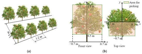
Spindle-shaped fruit trees are planted with a row spacing of approximately 3.5 m and a plant spacing of about 1.2 m. The ground is relatively flat, providing sufficient space for the operation of orchard machinery (as shown in Figure 1a). After pruning, spindle-shaped trees exhibit a reduced number of branching orders, featuring an upright central leader and limited growth of secondary branches on the primary branches. The primary branches measure approximately 0.4 m to 0.7 m in length, and the overall tree height is about 4.0 m. Fruits are mainly borne on the primary branches within a vertical range of 0.5 m to 3.5 m above ground. The apple tree harvesting operational area is analyzed as shown in Figure 1b. When harvesting one side of the canopy, the target picking volume can be defined as a cuboid measuring 1.4 m in width (x-axis), 0.7 m in depth (y-axis), and 3.0 m in height (z-axis). To enhance overall picking efficiency, multiple manipulators can be arranged vertically to cover the full height of the harvesting area. Accordingly, the manipulator’s workspace must extend at least 0.7 m along the y-axis. Since the mobile platform travels parallel to the tree row, the required workspace along the x-axis does not need to encompass the full width of the tree.
Figure 1.
Agronomic requirements of spindle tree fruit trees: (a) Plant spacing and row spacing of fruit tree planting. (b) The picking workspace for trees.
2.2. Picking Manipulator Design
2.2.1. Manipulator Structure Design
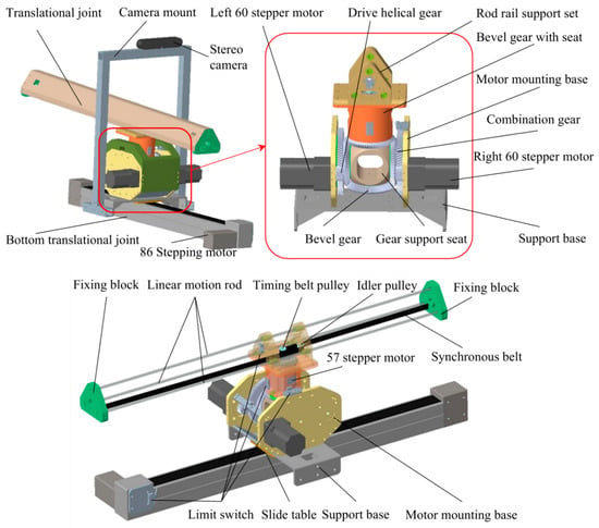
This research presents the design of a 4-DoF manipulator based on closed-loop stepper motors. Its basic structure is illustrated in Figure 2. The stereo camera is fixedly mounted onto the support base via a camera mount. Since the stereo camera moves along with the bottom translational joint, the bottom translational joint must remain stationary during the hand-eye calibration process to determine the transformation matrix between the coordinate system of the bottom translational joint and that of the camera. For the manipulator segment employing stepper motors, the equivalent motions of the yaw and pitch joints are realized through a differential gear structure driven by two closed-loop stepper motors. The bottom translational motion is facilitated by a synchronous belt guide rail. The support base is bolted onto the slide table of this guide rail, which is driven by an 86 stepper motor. The translational joint consists of a rod rail support set, a synchronous belt, a fixing block, a 57 stepper motor, among other components. The rod rail support set houses three smooth rods via linear bearings. The 57 stepper motor and an idler pulley are bolted onto it. A timing belt pulley is installed on the output shaft of the stepper motor. The synchronous belt meshes with this pulley, runs around the idler pulley, and its two ends are secured within the slots of the fixing block. Actuation by the 57 closed-loop stepper motor drives the timing belt pulley, causing the smooth rods to perform telescopic motion within the rod rail support set. One side of the fixing block is attached to the synchronous belt and the smooth rods, while the other side mounts the end-effector. The combination gear within the differential gear structure is formed by fixedly connecting a helical gear and a bevel gear. Drive helical gears are mounted on the output shafts of the left and right 60 closed-loop stepper motors. These drive helical gears mesh with the helical gears of the combination gears. The bevel gears of the two combination gears, a bottom bevel gear, and the bevel gear with seat mesh with each other in pairs. All bevel gears share identical structural parameters and are bolted onto a gear support base.
Figure 2.
4-DoF manipulator mechanism based on closed-loop stepper motor.
Limit switches are installed at appropriate positions on the manipulator to constrain the motion limits of each joint. These switches also serve to define the initial positions for the movement of each joint. The structural parameters of the drive helical gear, the driven helical gear of the combination gear, and the bevel gears were selected as shown in Table 1.
Table 1.
Basic parameters of gears.
The relationship between the rotation of the left and right 60 closed-loop stepper motors and the yaw and pitch motions is expressed by Equation (1).
where θ1 is the yaw angle, in degrees (°); θ2 is the pitch angle, in degrees (°); δ1 is the rotation angle of the left closed-loop stepper motor, in degrees (°); δ2 is the rotation angle of the right closed-loop stepper motor, in degrees (°); ng is the gear ratio between the drive helical gear and the driven helical gear of the combination gear.
When the left and right 60 closed-loop stepper motors rotate at the same speed but in opposite directions, they drive the bevel gear with seat to perform a pitch motion. When both motors rotate at the same speed and in the same direction, they drive the bevel gear with seat to perform a yaw motion. Accordingly, after the target’s three-dimensional coordinates and the manipulator’s inverse kinematic equations are used to calculate the manipulator’s pitch angle and yaw angle, the rotation angles of the left and right stepper motors can be determined using Equation (2).
2.2.2. Forward/Inverse Kinematic Equations of the Manipulator
The Denavit–Hartenberg (D–H, Craig version) convention is a standard method for describing the geometric relationship between links and joints in a serial-chain manipulator. The D–H parameters for the harvesting manipulator designed in this study are listed in Table 2.
Table 2.
D–H parameters of the simplified manipulator.
Each link of the manipulator is defined by four independent parameters: the link twist angle (αi), the link length (ai), the joint angle (θi), and the link offset (di). These parameters are determined after establishing the coordinate system for each joint based on the manipulator’s structure. Specifically: The link twist angle (αi) is the rotation about the Xi axis from Zi to Zi+1, with its sign determined by the right-hand rule. The link length (ai) is the distance along the Xᵢ axis (the common normal between joint axes) from Zi to Zi+1. The joint angle (θi) is the rotation about the Zi axis from Xi−1 to Xi, with its sign determined by the right-hand rule. The link offset (di) is the distance along the Zi axis from Xi−1 to Xi.
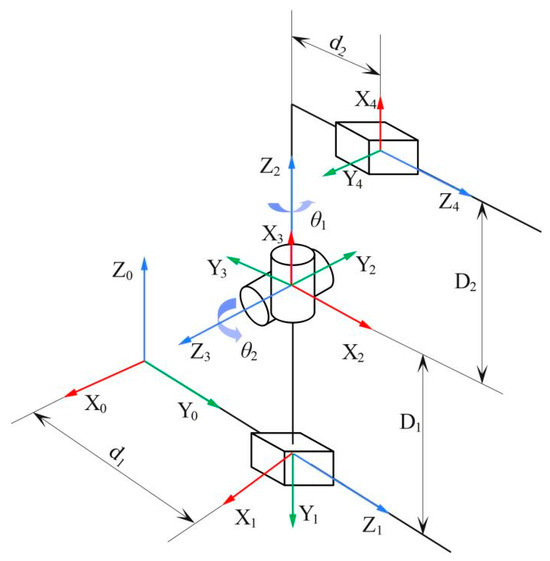
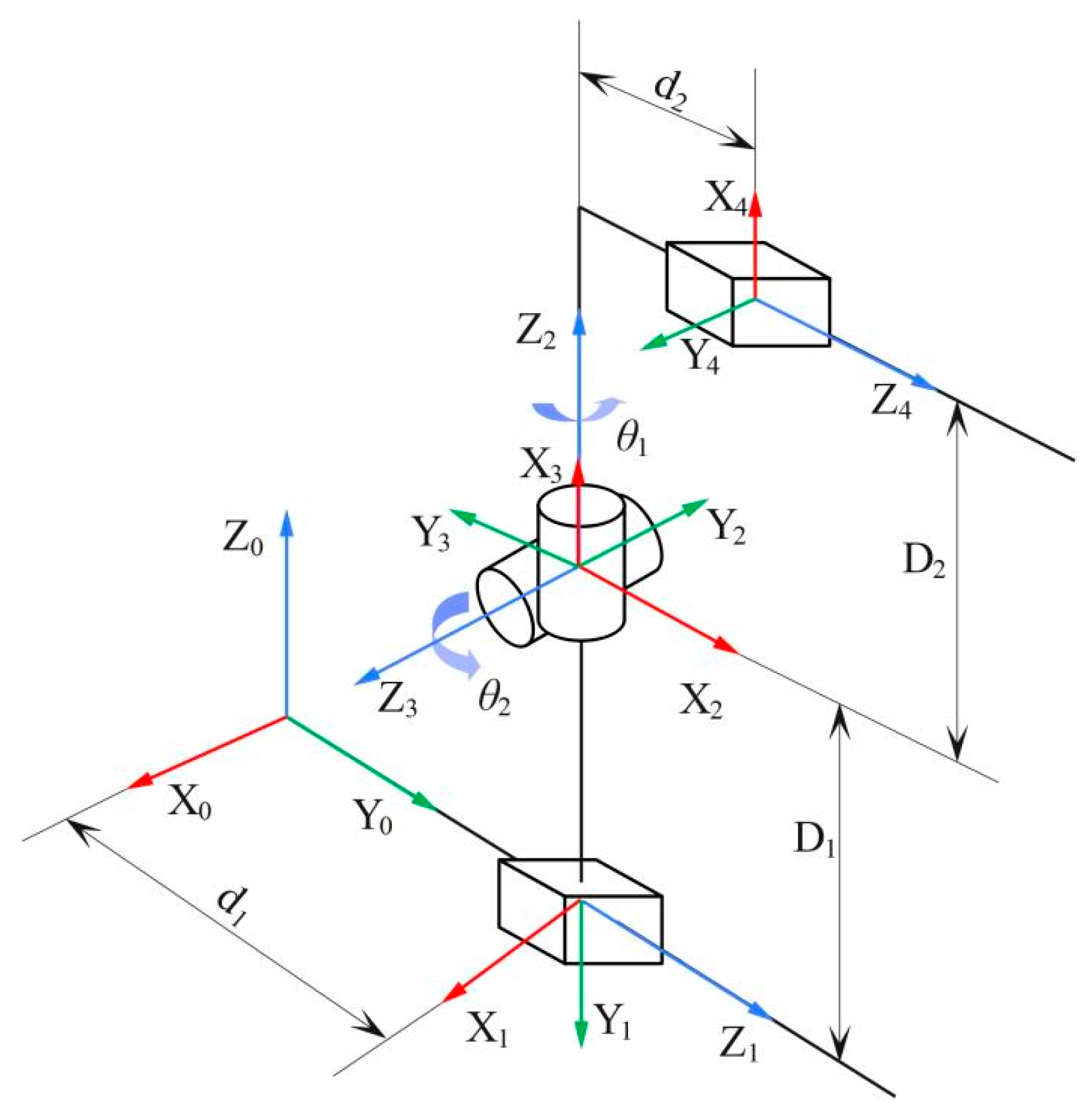
The coordinate system of the manipulator is defined as shown in Figure 3, establishing its kinematic model. The global coordinate frame of the manipulator is denoted as X0Y0Z0 (only the directions of the X-axis and Z-axis are indicated in Figure 3; the Y-axis direction follows the right-hand rule). A kinematic model of the manipulator was developed in Matlab (Version: 2019b). The Monte Carlo method was employed to test and visualize the workspace of the manipulator.
Figure 3.
Kinematic model of the picking manipulator.
Based on the D–H parameters, the homogeneous transformation matrices of the manipulator can be derived. These homogeneous transformation matrices are used to calculate the position of the end-effector in the manipulator’s global coordinate system, denoted as [x, y, z]T ∈ R3. The homogeneous transformation matrices between adjacent joint coordinates of the manipulator are given by Equations (3)–(7).
By substituting the homogeneous transformation matrices for adjacent manipulator joint coordinates (Equations (3)–(7)) into Equation (8) and performing the multiplication, Equation (9) is obtained.
Using the forward kinematics equations of the manipulator, the current pose of the harvesting manipulator can be calculated when the angles of all joints are known. The forward kinematics calculation formula is shown in Equation (10).
where β = arctan(D2/d2), °; x, y, and z represent the position of the end-effector in the manipulator’s global coordinate system, measured in mm; D1 is the distance between the Z3 axis of the pitch joint and the Z1 axis of the bottom translational joint, which is 81 mm; D2 is the distance between the Z4 axis of the translational joint and the rotation axis Z3 of the pitch joint, which is 178 mm; d1 is the displacement of the bottom translational joint, in mm; θ1 is the rotation angle of the yaw joint, in degrees (°); θ2 is the pitch angle of the pitch joint, in degrees (°); d2 is the displacement of the translational joint, in mm.
According to the inverse kinematics equations of the 4-DoF manipulator, once the target position is determined, the displacements of the bottom translational joint and the translational joint require an appropriate motion control algorithm for computation. After determining the displacement of the translational joint, the displacements of the yaw joint and the pitch joint can then be determined. The inverse kinematics equations are given by Equation (11).
2.2.3. Trajectory Planning of Manipulator Motion
Manipulator trajectory refers to the curves describing the displacement, velocity, and acceleration of the manipulator’s end-effector or its individual joints as functions of time. Trajectory planning for manipulators can be categorized into joint-space planning and Cartesian-space planning. Joint-space trajectory planning involves converting the path points that the end-effector must pass through, via inverse kinematics equations, into sequences of required positions for each joint. These position sequences for each joint are then fitted into smooth curves that comply with the motion constraints of the respective joints. This method is computationally simple and advantageous for avoiding manipulator singularities. However, it cannot guarantee that the end-effector follows a specific path between the start and end points, making it suitable for tasks where the intermediate path is not critical. Cartesian-space trajectory planning decomposes the desired end-effector path into a sequence of coordinates within the manipulator’s workspace that vary over time. This sequence is then converted into motion functions for each joint using inverse kinematics and the Jacobian matrix. While this method requires frequent inverse kinematic solutions and entails higher computational load, it allows for precise control of the end-effector’s path. It is therefore suitable for operations requiring specific end-effector trajectories. Considering the variability of the apple harvesting environment, the controllability of the end-effector’s trajectory can further ensure the safety of the end-effector.
During harvesting operations, continuous changes in the end-effector’s position and velocity are required to ensure smooth motion. Therefore, this study employs a harmonic acceleration/deceleration profile combined with linear interpolation. This approach ensures that both the velocity and acceleration of the end-effector motion are continuous curves, thereby improving motion smoothness and reducing impact vibrations caused by manipulator movement.
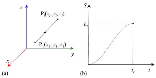
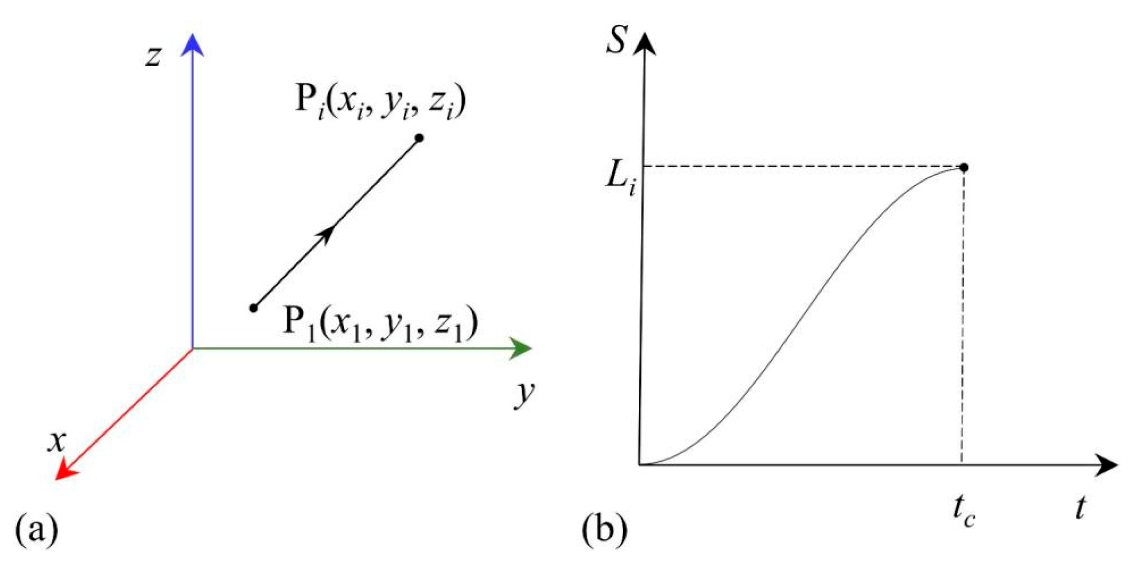
As shown in Figure 4, given the starting point P1 (x1, y1, z1) and the ending point Pi (xi, yi, zi) of the end-effector trajectory, the end-effector moves linearly from P1 to Pi within a specified time period tc. The displacement-time function governing this end-effector trajectory follows a harmonic law.
Figure 4.
Manipulator end interpolation motion. (a) Cartesian-space linear interpolation. (b) Manipulator end motion displacement-time curve.
The formula for calculating the distance Li between two points in Cartesian space is given by Equation (12).
Assuming the average velocity of the manipulator end-effector moving between these two points is v, the formula for calculating the end-effector position P(t) (x(t), y(t), z(t)) at any time t ∈ [0, tc] is shown in Equation (13).
where tc = Li/v, in seconds; λ(t) is the normalized time operator.
The displacement of each joint, q(t) (d1(t), θ1(t), θ2(t), d1(t)), can be solved using the manipulator’s inverse kinematics matrix and the time-varying function of the end-effector P(t), as shown in Equation (14).
where inkine() is the inverse kinematics solution for the manipulator.
The manipulator’s Jacobian matrix is used to transform the velocities and accelerations from the joint space into the end-effector’s velocities and accelerations in Cartesian space, as expressed by Equation (15). Consequently, the velocity and acceleration of each joint can be derived, as shown in Equation (16).
where J is the Jacobian matrix of the manipulator; are the joint velocity and acceleration matrices, respectively; V is the spatial velocity matrix of the manipulator’s end-effector; A is the manipulator’s spatial acceleration matrix.
2.2.4. Hand-Eye Calibration
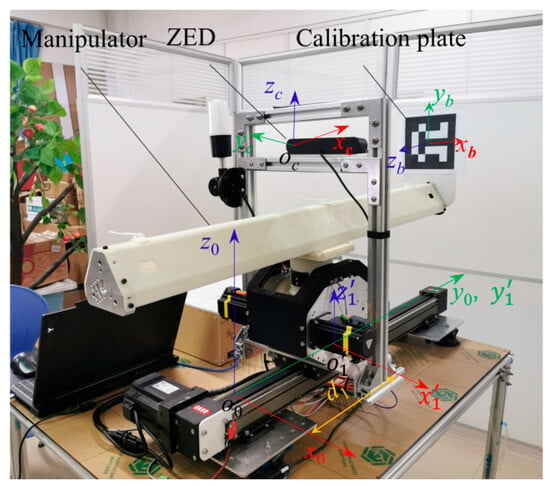
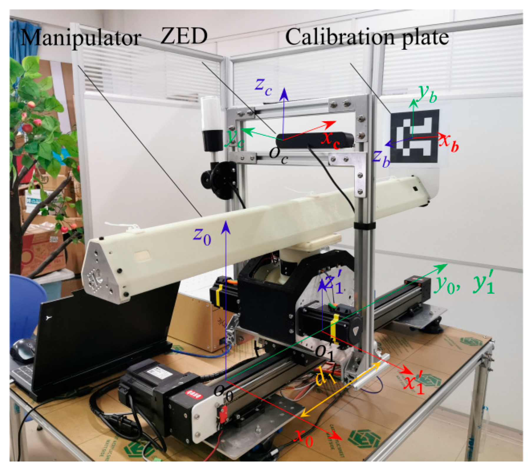
The stereo camera is fixed to the manipulator’s support base and moves with the bottom translational joint. Therefore, during the hand-eye calibration process, the bottom translational joint is kept stationary, while the 3-DoF manipulator (yaw, pitch, and translational joints) and the stereo camera form an eye-to-hand configuration. An Aruco calibration board is used to execute the hand-eye calibration procedure. The Aruco calibration board is mounted on the manipulator’s end-effector. Nine coordinate points, distributed as uniformly as possible within the manipulator’s workspace, are selected. The manipulator joints are controlled to position the calibration board at these specified locations, and the center coordinates of the calibration board are recorded. The Tsai-Lenz algorithm is then employed to compute the calibration results. A schematic diagram of the hand-eye calibration execution is shown in Figure 5.
Figure 5.
Schematic diagram of hand-eye calibration of the manipulator.
2.3. Design of Negative-Pressure Driven End-Effector
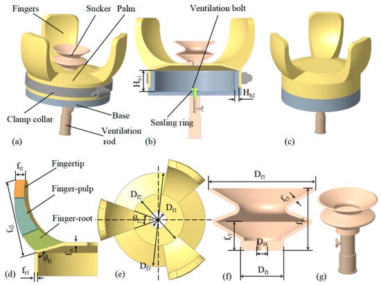
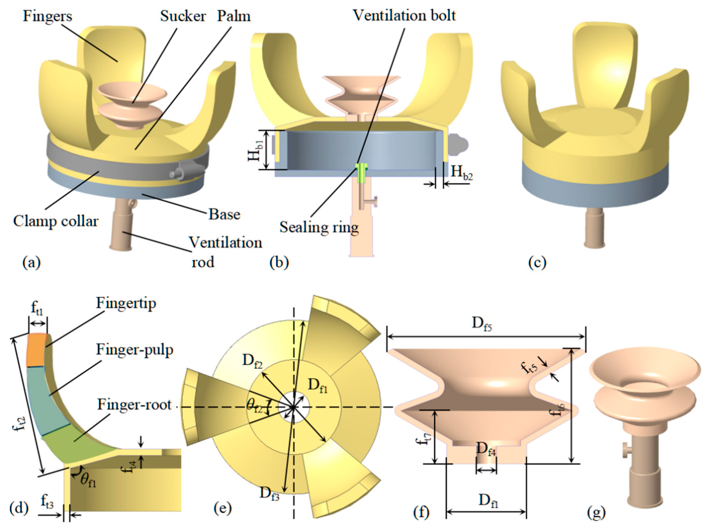
The negative-pressure driven end-effectors designed in this research (specifically, the suction-grasping soft end-effector (SGSE), grasping soft end-effector (GSE), and suction soft end-effector (SSE)) are primarily suitable for grasping spheroidal fruits. The three-dimensional structure of each part of the end-effector is shown in Figure 6, and the dimensional parameters are shown in Table 3. The GSE completes the gripping action under negative pressure to grab the object. The SGSE, GSE, and SSE are primarily designed for grasping spheroid fruits. The SGSE comprises fingers, a sucker, a base, and an air vent rod, as shown in Figure 6a. The GSE removes the sucker from the SGSE, as shown in Figure 6c. The SSE consists of a single sucker, as shown in Figure 6g.
Figure 6.
Structure design and size of the negative-pressure driven end-effectors. (a) Isometric side view of SGSE. (b) Section view of SGSE. (c) Schematic diagram of GSE structure. (d) Schematic diagram of finger structure. (e) Schematic diagram of palm structure. (f) Schematic diagram of suction cup structure. (g) Schematic diagram of SSE structure.
Table 3.
Parameters of the negative-pressure driven end-effectors.
Three fingers of the end-effector are evenly spaced at 120° intervals along the edge of the palm (as shown in Figure 6e). Each finger on the side wrapping around the fruit consists of three sections: the fingertip, finger pad, and finger root, connected via spline curves (as shown in Figure 6d). The fingertip and finger root each account for 25% of the finger length, while the finger pad occupies 50%. Rounded corners are applied to the fingertip to avoid sharp angles, and the finger pad features curved transitions to conform to the fruit’s surface. The finger root connects to the edge of the palm, which is angled outward to ensure the fingers are in an open position. A sucker is located at the center of the palm to adhere to the fruit. The palm is mounted on the base and securely sealed with clamps. The ventilation rod is fixed in the mounting hole of the base using a ventilation bolt and sealing ring (as shown in Figure 6b). The ventilation rod is connected to the negative pressure regulating valve, vacuum solenoid valve, and vacuum pump via tubing.
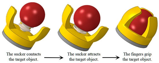
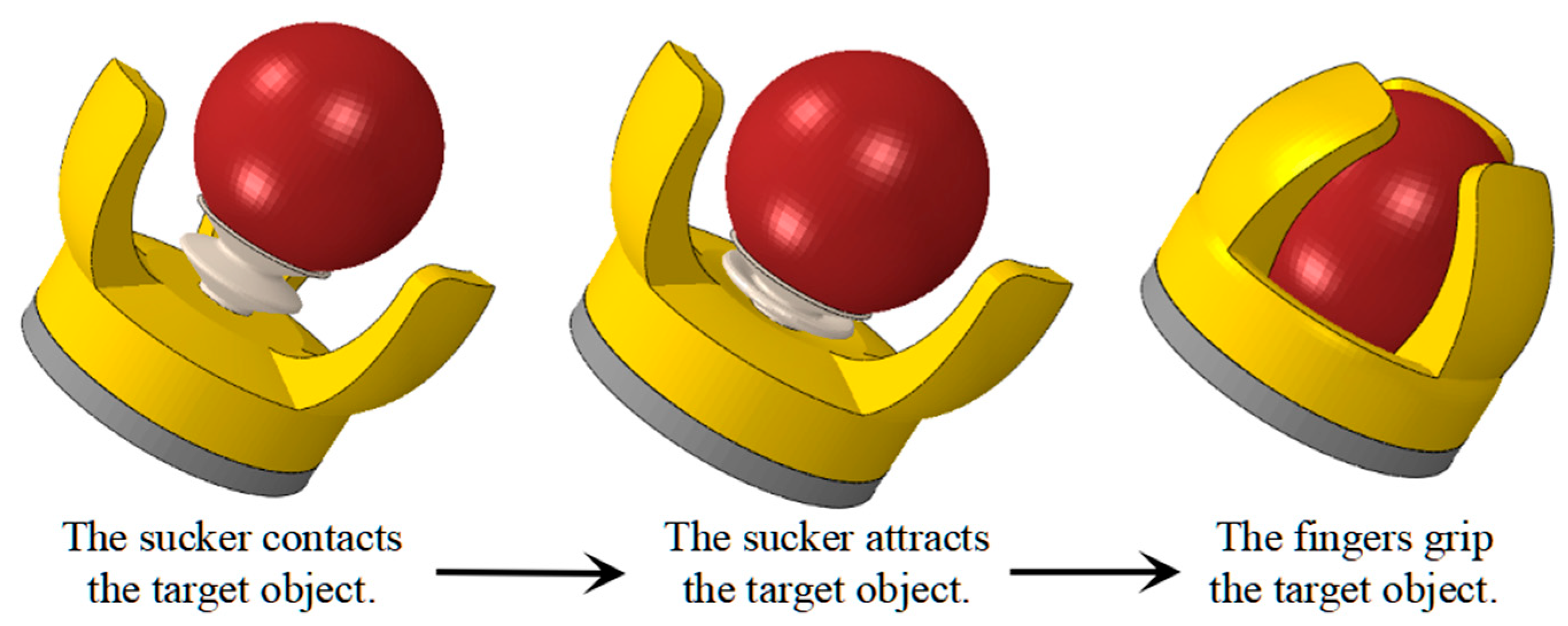
The process of the SGSE’s grasping the target object is shown in Figure 7. The soft finger-palm and sucker synergy structure achieve suction and clamping integrated grasping under negative pressure. The vacuum pump, solenoid valve, and pressure regulating valve are sequentially activated to initiate the grasping process. The sucker then contacts the surface of the target object to attract the object under the negative pressure. At this point, a hermetic chamber is formed between the palm and the base. As the vacuum pump continues to draw in air, the palm undergoes deformation, causing the fingers to retract inward, thereby gripping the object. When it is necessary to release the target object, the solenoid valve is closed, causing a rapid decrease in vacuum within the chamber of the end-effector. Consequently, the sucker loses the target object it grabbed, and the palm returns to its original state under the action of elasticity, thus releasing the target object.
Figure 7.
The process of the end-effector grabbing the target.
The SGSE integrates suction and gripping capabilities. It combines the advantages of both methods, with the gripping function helping to reduce the likelihood of slippage commonly associated with pure suction-based approaches. The sucker suction ensures that the target object is firmly secured before gripping, ensuring accuracy and stability during grasping. The GSE omits the sucker but retains an identical hermetic chamber geometry, and its size parameters are the same as those of SGSE. SGSE and GSE wrap the target in the palm and fingers, which can reduce the possibility of collision between the target and other obstacles, indicating their potential application in the field of agricultural robots.
2.4. Structure of Dual-Manipulator Harvesting Robot
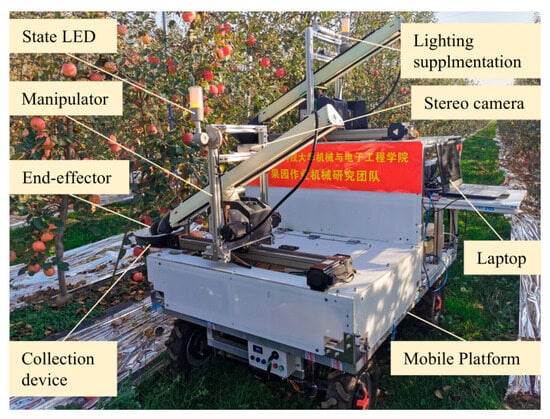
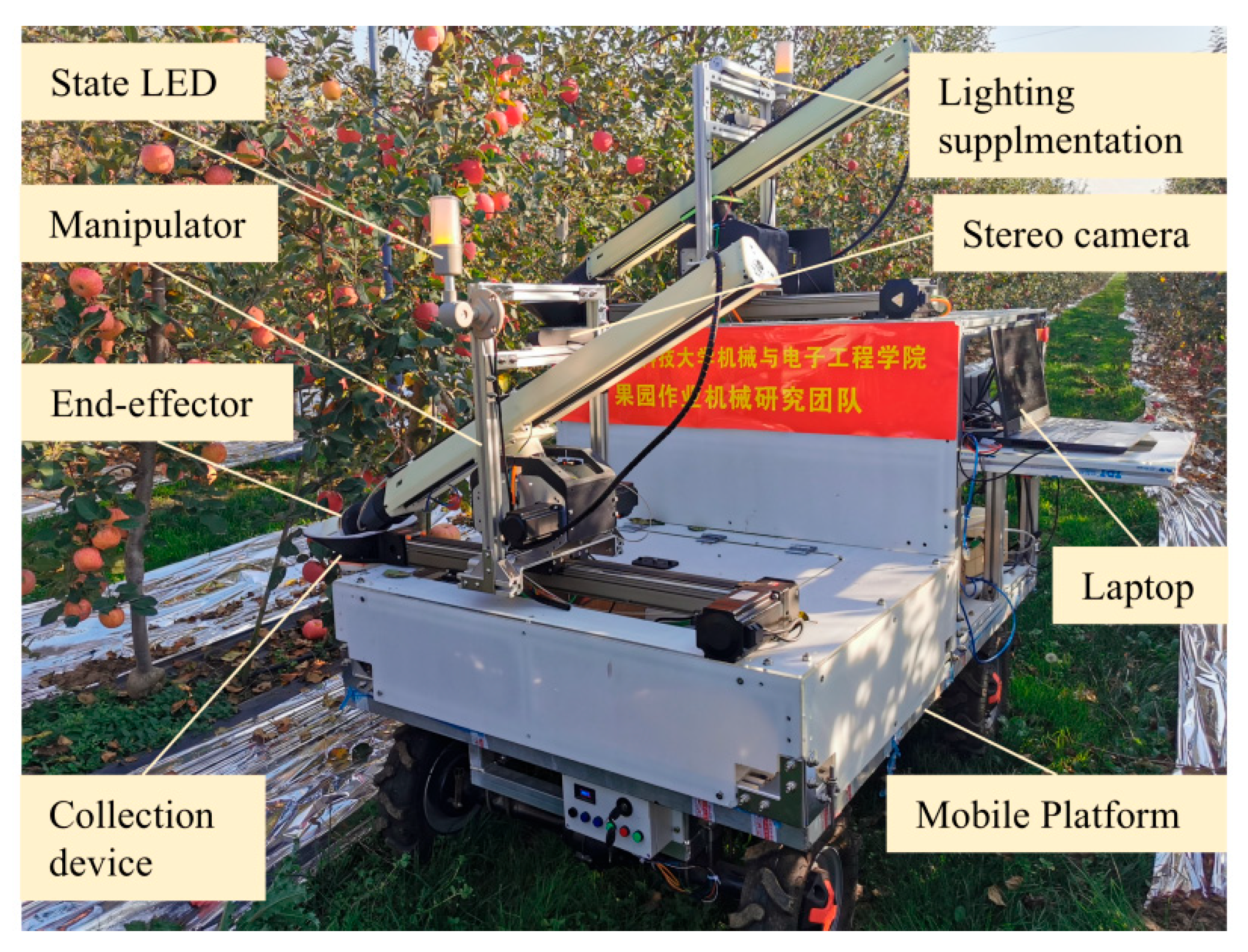
The experimental platform for the dual-manipulator harvesting robot is shown in Figure 8. The manipulators are 4-DoF manipulators based on closed-loop stepper motors. The apple harvesting robot is equipped with supplemental lighting, primarily consisting of suction-mounted light bars with a luminous flux of 200 lm, providing illumination for nighttime harvesting operations. Each manipulator is fitted with a status indicator to display its operational state. The mobile platform is driven by a 1.5 kW DC motor, has a payload capacity of 150 kg, a maximum travel speed of 3 m s−1, and is remotely controlled via a handheld remote. A mounting frame is fixed to the mobile platform using U-bolts, and the dual manipulators are securely installed on this frame using anchor bolts. The mobile platform, mounting frame, and manipulators all employ a modular design to facilitate flexible and convenient replacement of each module. The collection device consists of a funnel-shaped collection tray, silicone tubing, and a collection bin. The surface of the funnel-shaped tray is lined with ethylene-vinyl acetate (EVA) foam to prevent fruit damage upon contact. The tray is bolted to the end of the bottom guide rail of the manipulator. Its bottom is connected via silicone tubing to the collection bin, which is placed inside the mounting frame. Lu (2008) [37] demonstrated through drop tests that fruit bruising does not occur when the drop height is no greater than 0.040 m. Therefore, the fruit placement height from the end-effector to the collection tray was set at 0.040 m to avoid impact damage during fruit release. The stereo camera captures images of the area in front of the manipulator and transmits them to a portable computer. The portable computer uses recognition and localization algorithms to determine fruit positions and the picking sequence, then controls the manipulators and end-effectors to harvest the target fruits. The picked fruits are placed into the funnel-shaped collection tray and, guided by gravity, roll through the silicone tubing into the collection bin. Field harvesting trials were conducted from 2 to 7 November 2023, at the Yujia Orchard Cooperative in Baoji, Shaanxi Province (34°34′ N, 107°23′ E). The fruit variety harvested was ‘Yanfu’, from trees aged 8 years. The portable computer ran Ubuntu 18.04 LTS and ROS (Robot Operating System, version: Melodic), with an Intel i7-10750H CPU and an NVIDIA GeForce GTX 1650 GPU.
Figure 8.
Structural diagram of the harvesting robot test platform based on dual manipulator.
Three types of end-effectors designed in this study—namely, the SGSE, the GSE, and the SSE—were used to conduct three sets of harvesting trials. For each set of trials, the following metrics were recorded: (1) Suction/gripping success rate: the ratio of fruits successfully grasped (suction seal established or fingers securely closed) to the number of pickable fruits. (2) Detachment success rate: the ratio of fruits successfully separated from the branch to the number of fruits with successful suction/gripping. (3) Placement success rate: the ratio of fruits successfully deposited at the collection point to the number of successfully detached fruits. (4) Harvesting success rate: the ratio of fruits successfully collected (completing all stages from gripping through placement) to the total number of pickable fruits. This metric reflects end-effector performance on reachable targets. (5) Full-process success rate: the ratio of fruits successfully collected to the total number of detected and localized fruits. This metric reflects the overall system performance encompassing detection, localization, and harvesting. (6) Overall fruit damage rate: the ratio of harvested fruits exhibiting visible damage (body bruising or stem pulled) to the total number of successfully collected fruits. These metrics were used to evaluate the performance of the three end-effector types during harvesting operations.
All successfully collected fruits were individually labeled according to the end-effector type, then stored in single-layer foam-cushioned trays at room temperature for 48 h. Damage was then assessed by visual inspection under uniform indoor lighting and classified into the following categories. (1) Body damage: any visible discoloration, soft-tissue deformation or skin break on the fruit surface. (2) Stem pulled: complete separation of the stem from the fruit. Intact stems with minor bending were not counted as damage. Fruits could exhibit multiple damage types simultaneously (e.g., both bruising and stem pulled); the overall damage rate counts each fruit once regardless of the number of concurrent damage types.
2.5. Fruit Detection and Location
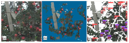
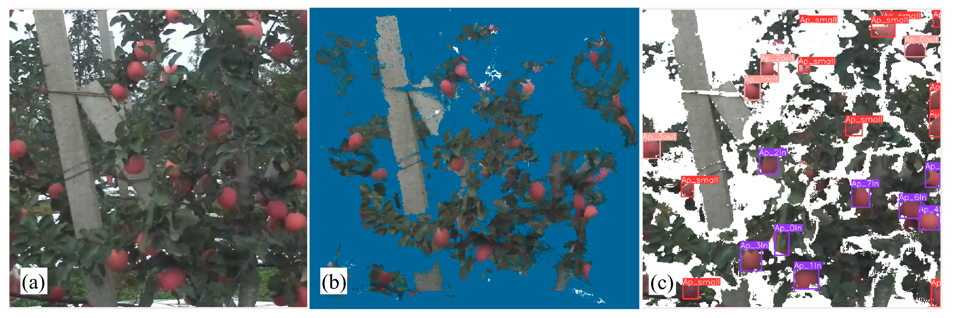
The visual detection system primarily consists of a stereo camera. The stereo camera captures orchard information in front of the manipulator, with an original image size of 1920 × 1080 pixels. Since the image area far exceeds the manipulator’s workspace, the captured image is cropped to 740 × 740 pixels based on the workspace constraints (as shown in Figure 9a). The corresponding point cloud data is then filtered using a depth threshold (as shown in Figure 9b). Next, the image is fed into the Lad-YXNet [24], which was improved by our team based on YOLOX-Tiny, to detect fruits, obtaining the pixel coordinates of the top-left and bottom-right corners of the apple bounding boxes (as shown in Figure 9c). The model was trained on a custom dataset comprising 1200 annotated apple images collected under diverse orchard conditions (varying lighting and occlusion levels). The training input resolution was 640 × 640 pixels, with a weight decay of 5 × 10⁻⁴, a momentum factor of 0.937, and a learning rate schedule combining warm-up training with cosine annealing. The inference confidence threshold was set to 0.5, and the non-maximum suppression (NMS) intersection-over-union (IoU) threshold was set to 0.45. The trained model achieved an average precision (AP) of 94.88%; further details are provided in our previous work [24].
Figure 9.
Fruit recognition and positioning by visual perception system. (a) Original image after cropping. (b) Mapping 3D point cloud image. (c) Recognition and positioning results.
These two-pixel coordinates are mapped onto the 3D point cloud output by the stereo camera to extract the point cloud data corresponding to the apple bounding box. In Open3D (v0.16.0), the raw point cloud within each detected fruit’s bounding-box region was sequentially processed through three filtering stages (filter parameters were empirically determined through field testing): (1) voxel downsampling with a voxel size of 2 mm to reduce point density while preserving spatial structure; (2) statistical outlier removal with a neighbor count of 100 and a standard deviation multiplier of 0.2; (3) radius outlier removal with a minimum point count of 10 and a neighborhood radius of 10 mm. Finally, the filtered point cloud is averaged, and this average value is used as the fruit’s positional coordinate.
For occluded fruits, the point cloud data are sparse. A preliminary test correlating bounding-box size with actual occlusion severity indicated that fruits with a bounding-box side length below 35 pixels were substantially occluded, which would increase the difficulty of subsequent end-effector grasping. Therefore, bounding boxes below 35 pixels are excluded as picking targets and are marked with a red box in the image. Fruits are initially screened based on the manipulator’s workspace: those outside the workspace are marked with a pink box, while those within the workspace are marked with a purple box (as shown in Figure 9c).
2.6. Picking Sequence Planning
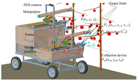
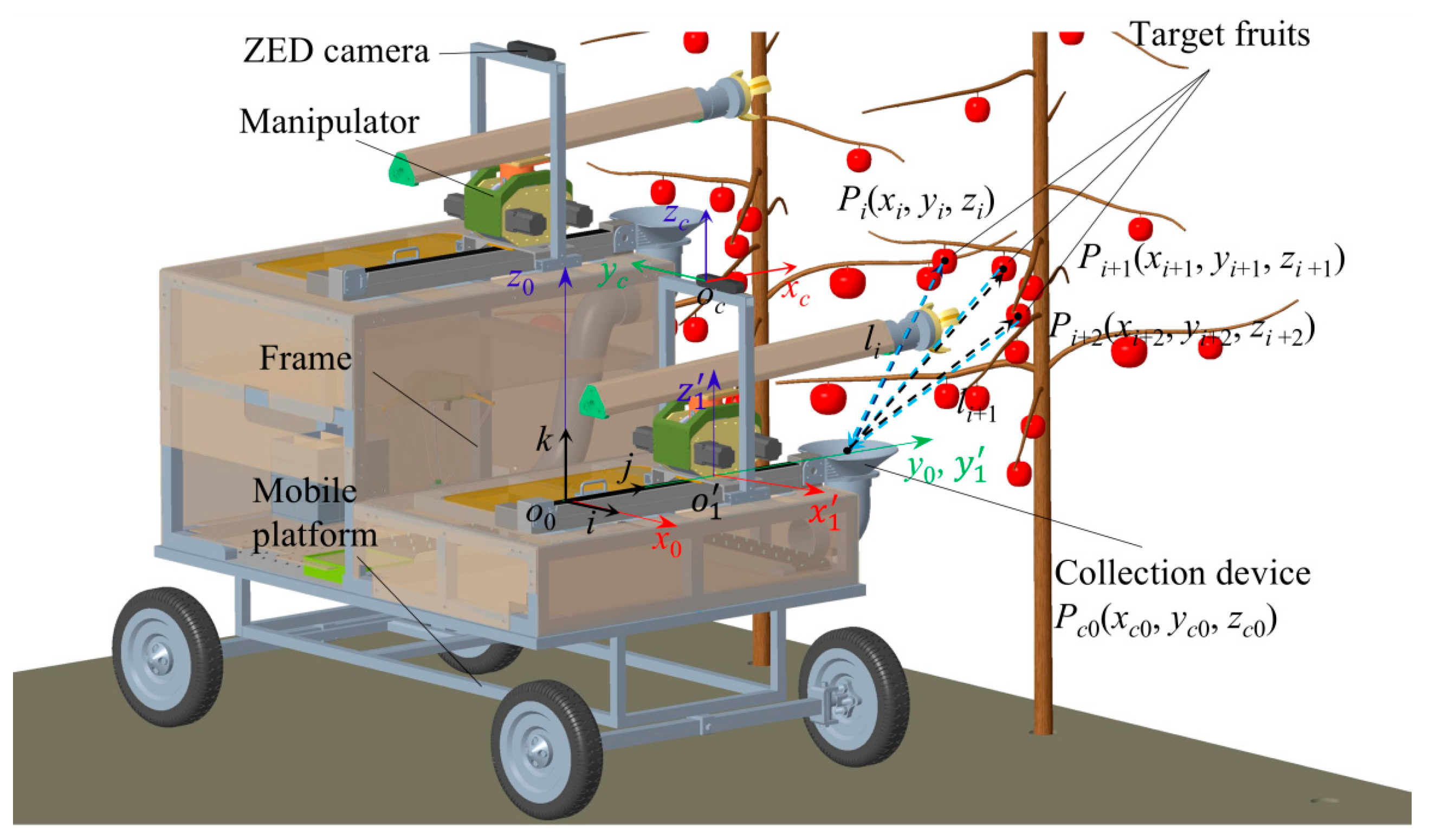
When harvesting fruits continuously in an orchard, an appropriate picking sequence contributes to improving overall harvesting efficiency. Therefore, this study analyses the fruit picking sequence. The placement point is defined as a fixed point Pc0. Assuming several apples Pi (xi, yi, zi) (i = 1, 2, 3, …, n) are randomly distributed within the manipulator’s workspace, and the manipulator’s average operating speed is a constant va, the time required to traverse and pick all fruits under ideal conditions (ignoring factors such as collisions and occlusions during the picking process) is calculated. As shown in Figure 10, the harvesting mode in this study requires the manipulator to return to the placement point to deposit the fruit after each pick. The manipulator’s movement distance and movement time are given by Equations (17) and (18), respectively.
where li represents the movement distance of the manipulator for a single fruit picking cycle, in mm; Tp is the total time consumed to harvest n fruits, in s.
Figure 10.
Analysis of fruit picking sequence planning.
Analysis of Equation (18) indicates that, under the condition of returning to the placement point after picking each fruit and with a constant average speed, the fruit picking sequence does not affect Tp. However, considering the issue of mutual occlusion among fruits during the harvesting process, adopting a picking sequence from the outside inward can help minimize occlusion problems. Additionally, harvesting fruits within the manipulator’s workspace from the bottom upward can avoid inadvertent contact with other fruits during the operation. Therefore, this study determines the picking sequence as follows: first from the outside inward, then from the bottom upward, and finally from left to right, with each rule having successively lower priority.
2.7. Field Test
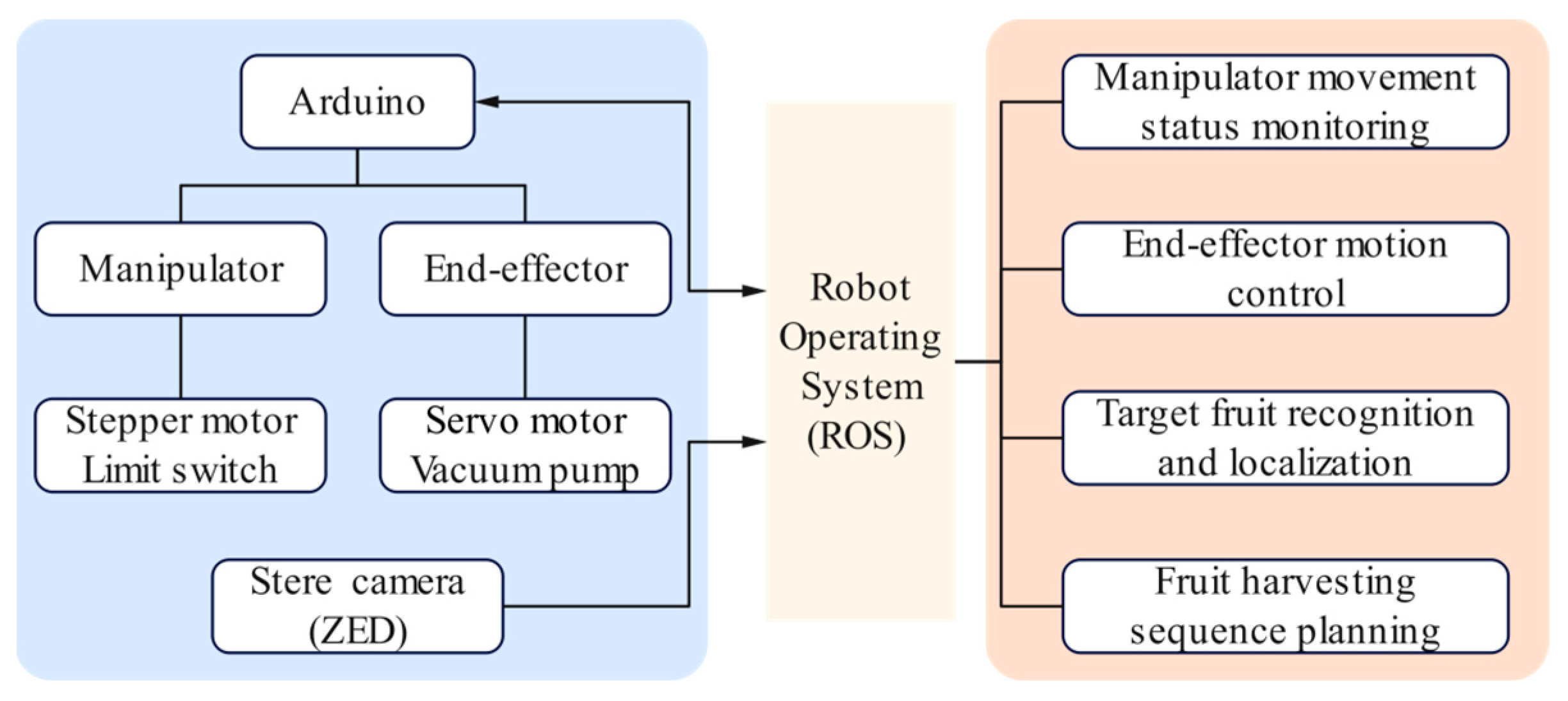
The host computer system in this research operates on Ubuntu 18.04, and an intelligent apple harvesting robot control framework was established based on ROS, as illustrated in Figure 11. The ZED camera (Stereolabs Inc., San Francisco, CA, USA), manipulators, and end-effectors all communicate with the ROS system via USB. ROS monitors the motion states of the manipulators and coordinates various tasks based on their status, including target fruit recognition and localization, planning of the manipulator picking sequence, and fruit grasping and placement by the end-effectors.
Figure 11.
ROS-based apple harvesting robot system structure.
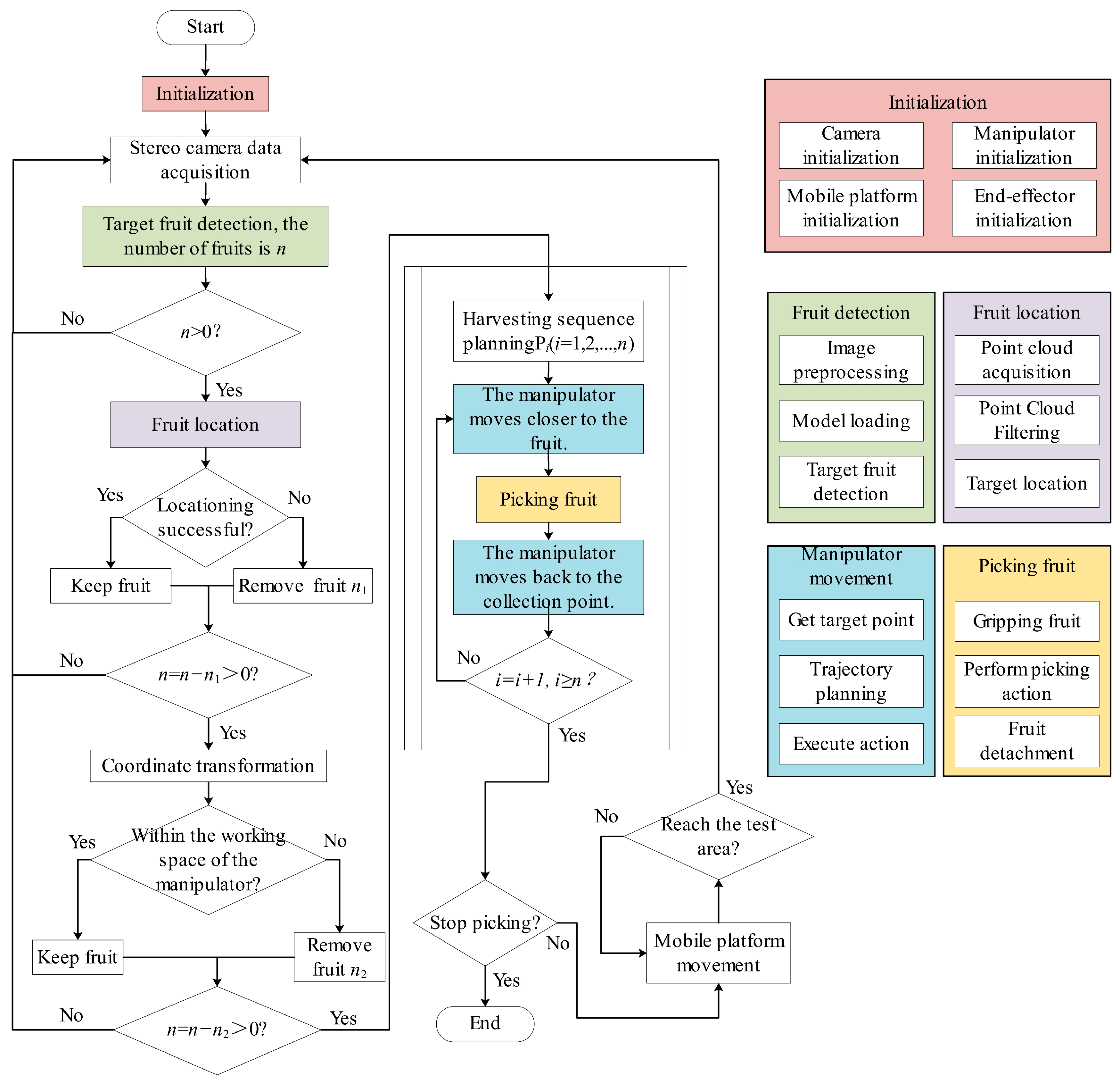
The workflow for the harvesting robot’s field operations is shown in Figure 12. First, the devices are initialized: the mobile platform moves to a suitable harvesting position, and the manipulators and end-effectors are reset to their home positions. Next, images and point cloud data from the stereo camera are acquired to recognize and localize target fruits. Coordinate transformation is performed based on the fruit locations to determine if they fall within the manipulator’s workspace. The harvesting sequence is then planned, and the coordinates are sent to the manipulator controller. The controller directs the manipulator to approach the target fruit. Once the end-effector reaches the target position, it grasps the fruit.
Figure 12.
Schematic diagram of the field harvesting test process.
After the manipulator, in coordination with the end-effector, completes the picking action, it returns to the designated collection point to deposit the fruit before proceeding to harvest the next target fruit. This cycle continues until all currently identified target fruits have been harvested. The stereo camera then scans the area to check for any remaining harvestable fruits. If no further fruits are detected, the operator uses the remote handle to control the mobile platform’s movement to the next suitable position to continue the harvesting test.
3. Results
3.1. Simulation Results of the Simplified 4-Dof Manipulator
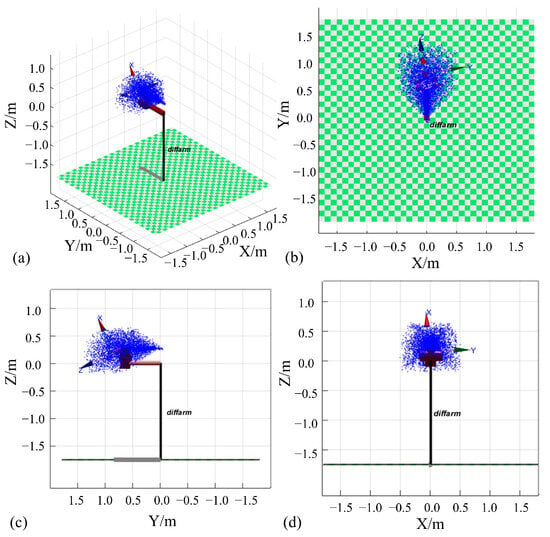
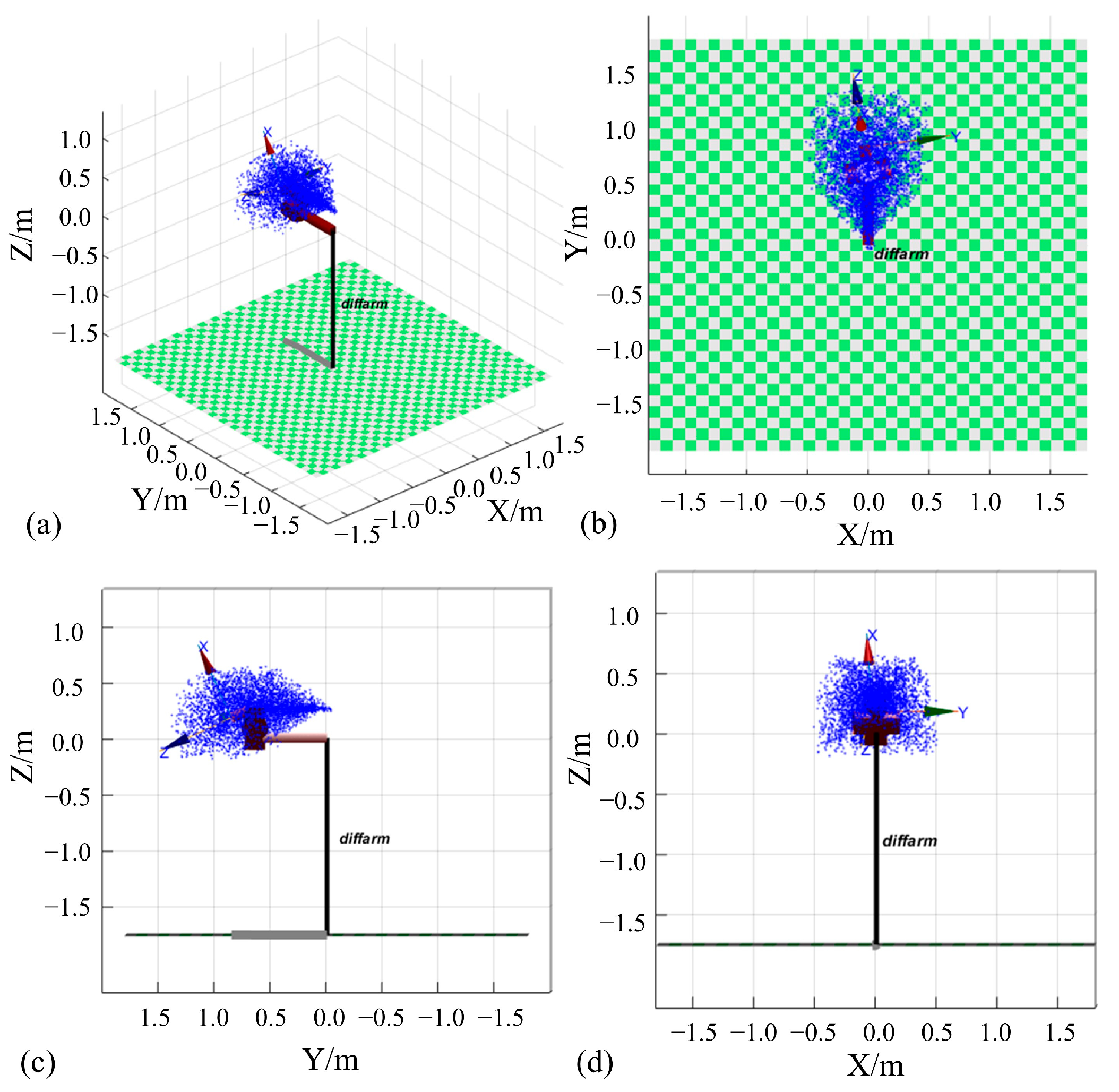
A visual kinematic model of the manipulator was established in Matlab, as shown in Figure 13. The manipulator’s workspace approximates an open conical shape. Monte Carlo simulations indicate that the achievable range for the end-effector along the three axes is x ∈ [−0.463 m, 0.463 m], y ∈ [0.000 m, 1.42 m], z ∈ [−0.198 m, 0.648 m]. The total vertical (Z-direction) workspace is 0.846 m. Given that the fruit-bearing height of a single tree is approximately 3 m, a future multi-manipulator harvesting scheme to improve overall efficiency would require four such manipulators to cover the entire tree. This study employs a dual-manipulator setup to validate the feasibility of this concept.
Figure 13.
Schematic diagram of the simplified 4-DoF manipulator workspace. (a) Axial side view of the workspace. (b) Top view of the workspace. (c) Left view of the workspace. (d) Rear view of the workspace.
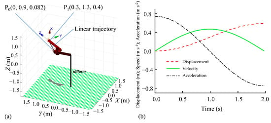
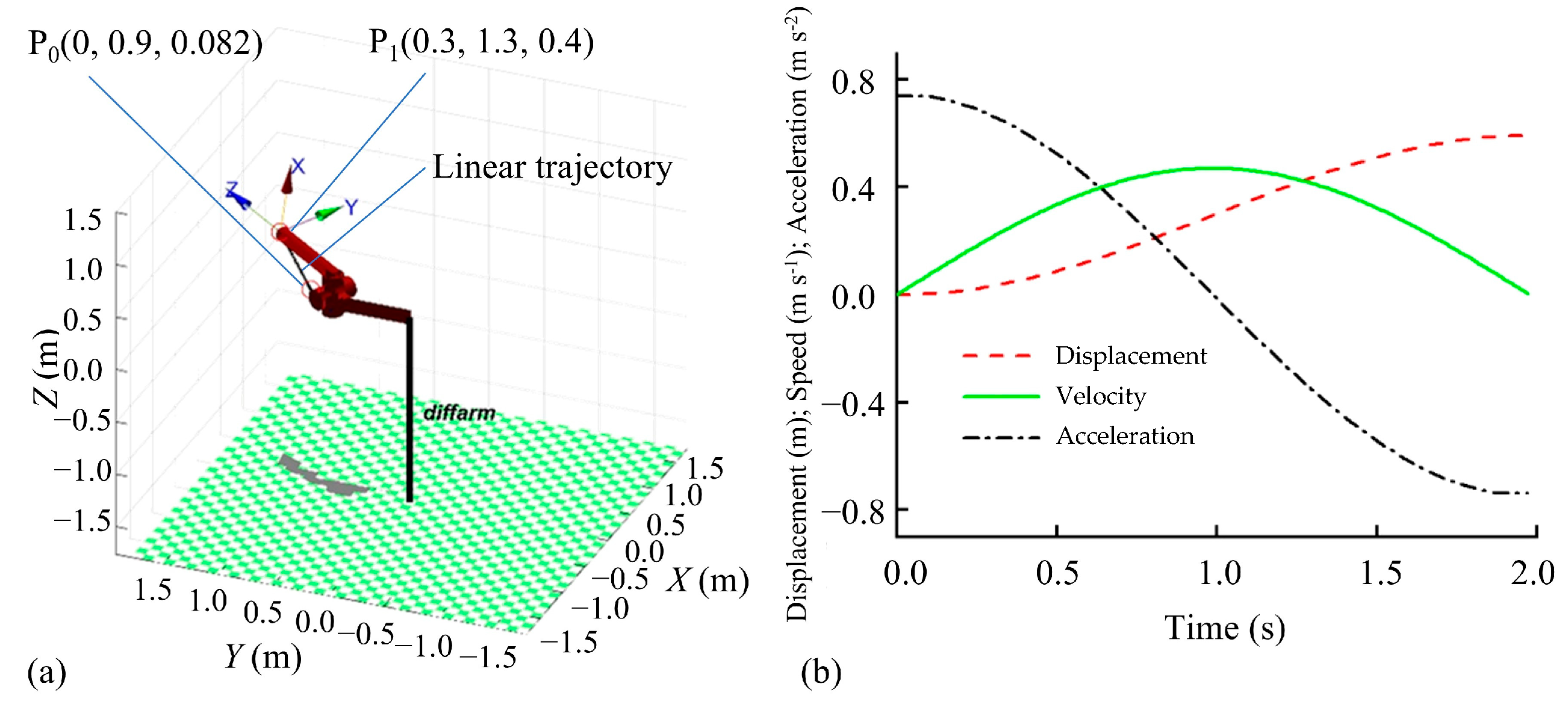
Numerical simulations of the 4-DoF manipulator’s end-effector trajectory were performed using Matlab. With the starting point P0 (0.000 m, 0.900 m, 0.082 m) and the target point P1 (0.300 m, 1.300 m, 0.400 m) selected, and the end-effector’s average speed set to 0.3 m s−1, the simulation results for linear interpolation with a harmonic acceleration/deceleration constraint are shown in Figure 14. As seen in Figure 14a, the 4-DoF linear interpolation algorithm constrains the end-effector’s path between the two points to a straight line. The velocity and acceleration curves are derived by applying a gradient algorithm to the displacement-time curve. Figure 14b demonstrates that the end-effector trajectory complies with the harmonic acceleration/deceleration constraint, and the displacement, velocity, and acceleration curves are all smooth.
Figure 14.
Simulation results of linear interpolation motion of the manipulator. (a) End motion trajectory of manipulator. (b) End motion displacement, velocity, and acceleration curve of manipulator.
3.2. Hand-Eye Calibration Results
The hand-eye calibration results are presented in Table 4, showing a mean positional error of 4.7 ± 2.7 mm. The primary sources of error in the manipulator’s end-effector positioning include: (1) errors in the coordinate system transformations between the manipulator’s joints; (2) discrepancies between the actual structural dimensions of the joints and the model dimensions used by the manipulator’s control system; (3) errors arising from mechanical factors such as backlash, deformation, and friction; and (4) measurement methods that did not account for errors in the z-axis direction. Improving the manipulator’s control accuracy requires further research in areas such as joint parameter identification, calibration, and compensation.
Table 4.
Hand-eye calibration results.
3.3. Field Harvesting Trial Results and Analyses
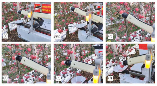
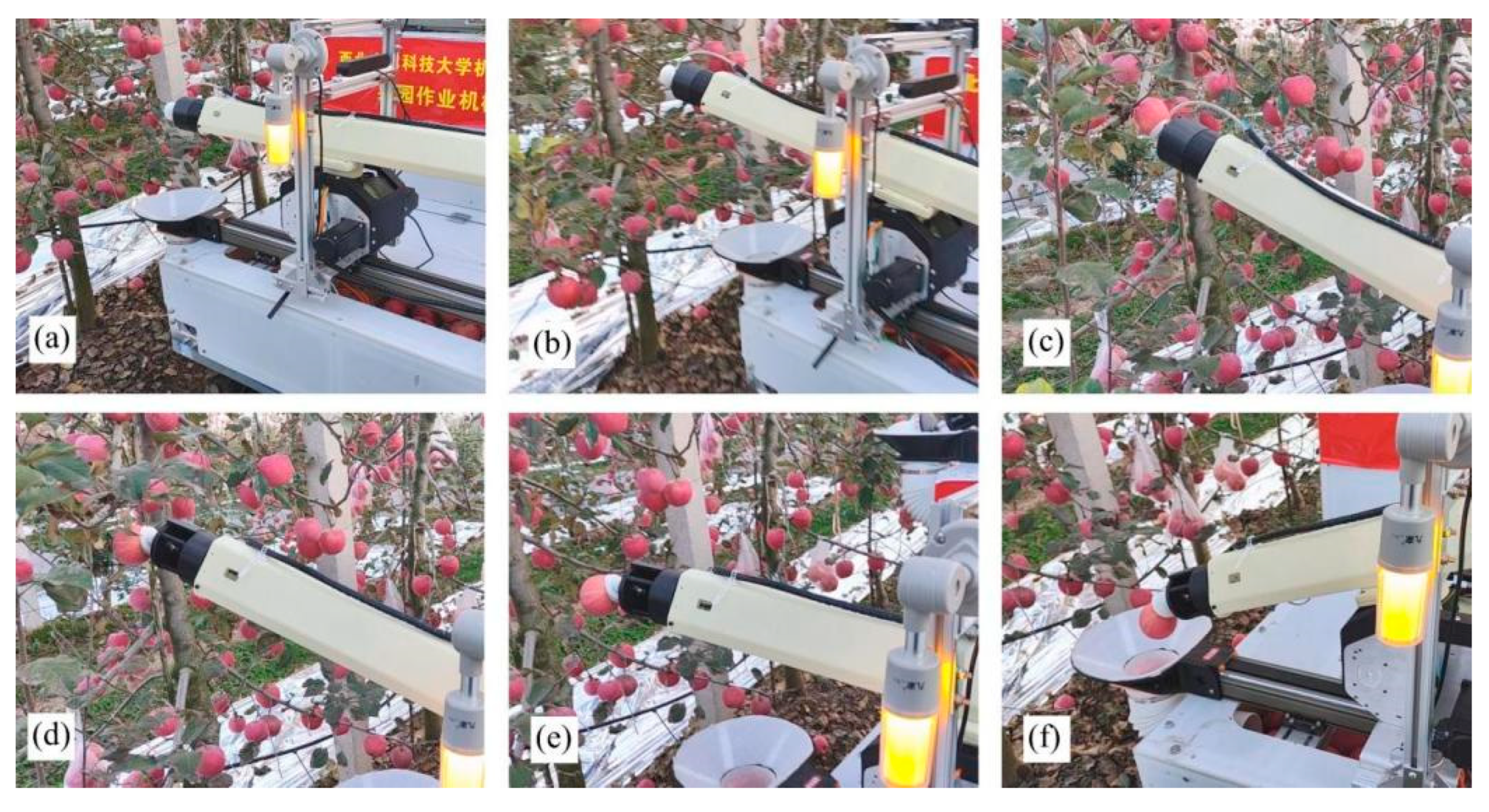
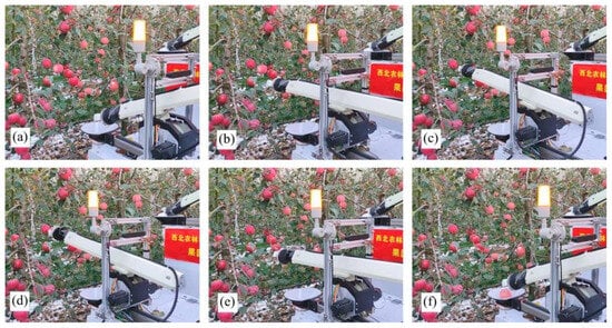
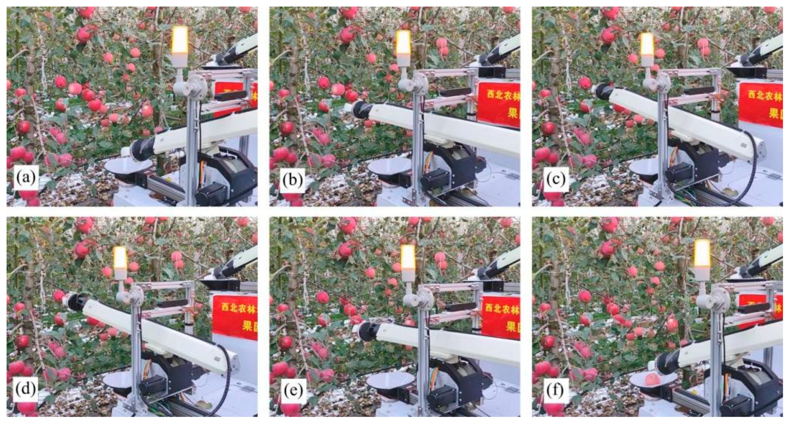
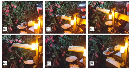
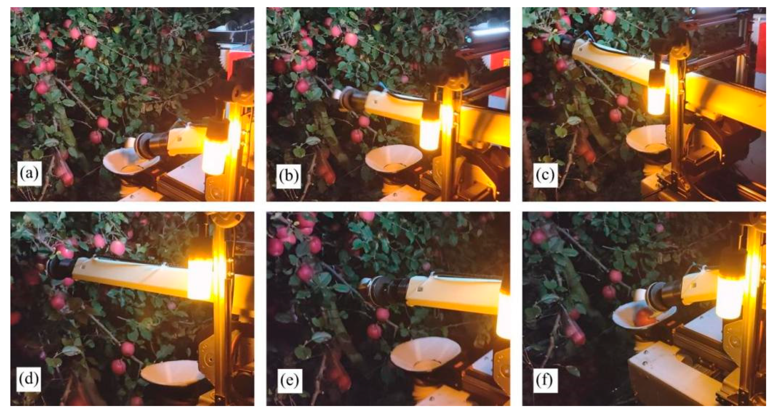
Field harvesting trials were conducted to evaluate the performance of three end-effector types: the SGSE, GSE, and SSE. The harvesting process for each end-effector primarily comprised the following stages: initial state, approaching the fruit, suction/gripping the fruit, detaching the fruit, returning to the collection point, and placing the fruit, as illustrated in Figure 15, Figure 16 and Figure 17, respectively.
Figure 15.
SSE harvesting test process. (a) Initial state. (b) Approaching the fruit. (c) Fruit attachment. (d) Picking to detach the fruit. (e) Returning to the placement point. (f) Placing the fruit.
Figure 16.
GSE harvesting test process. (a) Initial state. (b) Approaching the fruit. (c) Fruit attachment. (d) Picking to detach the fruit. (e) Returning to the placement point. (f) Placing the fruit.
Figure 17.
SGSE harvesting test process. (a) Initial state. (b) Approaching the fruit. (c) Fruit attachment. (d) Picking to detach the fruit. (e) Returning to the placement point. (f) Placing the fruit.
The trials demonstrated that all three end-effector types were capable of completing the fruit harvesting task, though their performance metrics varied. The field harvesting results are presented in Table 5. Detected fruits is the number of all fruits on the camera’s field of view that were successfully detected by the vision system. A total of 336 fruits were detected and located, accounting for 65.75%. The remaining 175 fruits were not successfully detected or located due to: (1) occlusion or lighting conditions preventing recognition (71/175), resulting in 86.11% orchard recognition accuracy for the Lad-YXNet model [24]; (2) failure to generate point cloud data or excessively sparse point clouds due to branch/leaf occlusion, lighting, or distance (43/175); and (3) successful localization but position outside the manipulator’s workspace (61/175). Among the detected and located fruits, approximately 75.89% were considered pickable. Reasons for excluding fruits from the pickable count include: (1) structural failures of the manipulator or end-effector (3/81); (2) excessive localization error caused by leaf occlusion (37/81); (3) misidentified or mislocated fruits (5/81); (4) fruits beyond the manipulator’s workspace (14/81); and (5) fruit loss during the harvesting process (24/81).
Table 5.
Harvesting results between three types of end-effectors.
Causes of suction failure for the SSE and SGSE include longitudinal positional error (SSE: 9/21; SGSE: 7/21), fruit oscillation (SSE: 2/21; SGSE: 1/21), obstruction by branches or leaves (SSE: 8/21; SGSE: 9/21), and atypical fruit growth posture (SSE: 2/21; SGSE: 4/21). Gripping failures of the GSE resulted from: (1) excessive fruit localization error (7/18); and (2) obstruction by branches or leaves along the picking path (11/18). Detachment failures of the SSE were attributed to: (1) insufficient suction leading to slippage between the fruit and end-effector (4/7); and (2) fruit growing on slender branches that exhibited large bending deformation during picking (3/7). Detachment failures of the GSE and SGSE were caused by: (1) fruit growing on slender branches that underwent large bending deformation (GSE: 1/4; SGSE: 1/2); (2) unstable grasping by the end-effector (GSE: 1/4); and (3) branch obstruction preventing end-effector rotation (GSE: 2/4; SGSE: 1/2). Placement success rates for all three end-effectors were relatively high, though failures occurred due to: (1) contact with branches or fruits during the return path causing fruit dislodgement (SSE: 2/4; GSE: 2/2); and (2) inertial forces from manipulator motion causing fruit detachment (SSE: 2/4).
As shown in Table 5, the proportion of pickable fruits among those detected remained relatively consistent across the three end-effectors, ranging from 74.73% to 77.78%. This consistency indicates that this metric is primarily determined by the vision system and the manipulator’s workspace rather than by end-effector design. Such uniformity validates the experimental controls and demonstrates that the performance differences observed in subsequent stages are indeed attributable to end-effector characteristics.
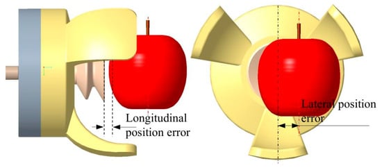
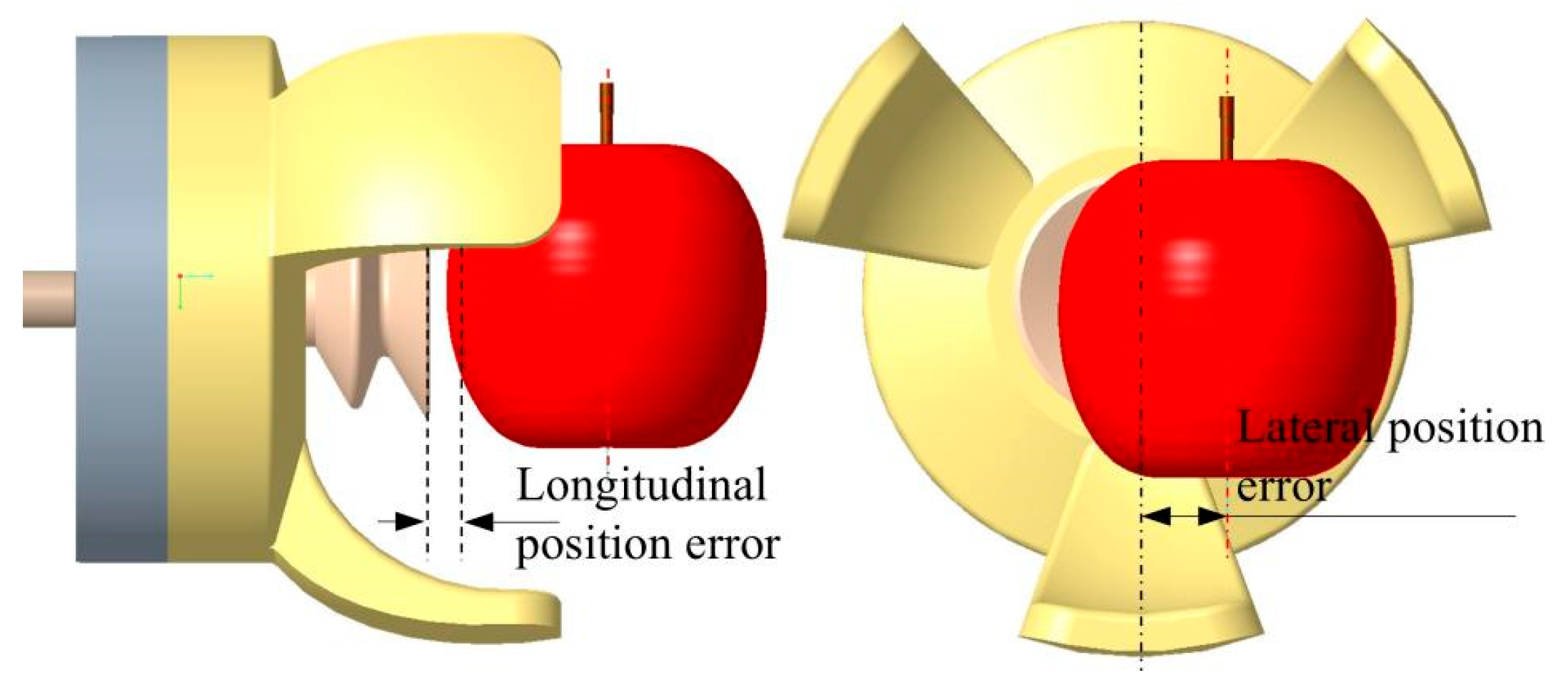
Table 5 reveals differentiated success rates of suction/gripping among the three end-effectors. The GSE achieved 85.60%, while the SGSE and SSE reached 69.12% and 66.67%, respectively. Field trials demonstrated that the GSE exhibited low sensitivity to both lateral and longitudinal positional errors (Figure 18). In contrast, although the SSE and SGSE showed some tolerance to lateral positional errors, they displayed high sensitivity to longitudinal positional errors—the primary cause of suction/gripping failures (9 of 21 failures for the SSE and 7 of 21 for the SGSE). This sensitivity arises because both the SSE and SGSE require an effective negative-pressure seal with the fruit surface. When the fruit surface is irregular, positional error is large, or branches/leaves cause occlusion, an effective seal cannot be established.
Figure 18.
Schematic of position errors during end-effector suction/gripping of fruit.
The mechanical advantage of the GSE stems from its ability to physically conform to the fruit surface over a wider spatial tolerance range, providing superior tolerance to positional errors. This enables secure gripping even when initial contact occurs at a suboptimal position, thereby compensating for cumulative localization errors inherent in the vision-to-motion transformation process. (A quantitative analysis of gripping force and positional tolerance for the three end-effectors has been submitted for publication and is currently under review). This indicates that end-effectors with good positional tolerance are more conducive to improving suction/gripping success rate. The 18 GSE failures were mainly caused by obstacles along the picking path (61.11%) and excessive localization errors (38.89%), suggesting that although the gripping mechanism possesses positional tolerance, a relatively obstacle-free picking path remains necessary.
The detachment success rates of the GSE and SGSE both exceeded 95% (96.26% and 95.74%, respectively), while that of the SSE was only 83.33%. Under equivalent negative-pressure conditions, the GSE and SGSE provide greater gripping force. The SGSE performance in this stage approached that of the GSE, indicating that gripping finger design can effectively compensate for the grasping-force deficiency of purely suction-based end-effectors. Although both the GSE and SGSE provide sufficient gripping force during picking, detachment failures can still occur due to flexible branch deformation or branch obstruction impeding detachment motion execution. Therefore, considering the relative pose and physical properties between branches and fruits during detachment is beneficial for improving success rates. Placement success rates remained high across all three end-effectors (88.57% to 100%). The GSE and SGSE achieved 98.06% and 100%, respectively, indicating that once fruit is successfully detached, loss risk during return transport is minimal for gripping mechanisms with stronger holding capability. This is primarily attributed to the enveloping grasp provided by the GSE and SGSE fingers.
The GSE achieved the highest overall harvesting success rate of 80.80% (101 of 125 pickable fruits), significantly outperforming the SSE (49.21%, 31 of 63 fruits) and SGSE (66.18%, 45 of 68 fruits). The GSE harvesting success rate represents improvements of 64.32% over the SSE and 22.08% over the SGSE. The full-process success rate for the GSE (ratio of successfully collected fruits to detected fruits) reached 61.59%.
Fruit damage rate is a key quality metric for commercial harvesting systems, as excessive damage directly affects marketability and economic returns. Harvested fruits were stored at room temperature for 48 h and then examined for visible surface damage. The main damage types observed were body bruising and stem pulled. Analysis indicates that bruising primarily occurred during collection due to fruit-to-fruit collisions, while stem pulled mainly occurred during detachment. Some fruits exhibited both damage types. The stem pulled rates for the SSE, GSE, and SGSE were 9.68%, 7.92%, and 8.89%, respectively. The body bruising rates were 6.45%, 5.94%, and 4.44%, respectively. The overall damage rates were 12.90%, 10.89%, and 13.33%, respectively. The primary cause of stem pulled is the detachment action. Although the twist-pull pattern requires less force than other detachment modes, it inevitably carries some probability of causing stem detachment—a limitation compared to manual harvesting. However, this indicates that stem pulled rate could be further reduced by improving detachment strategy.
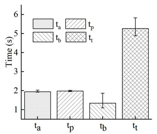
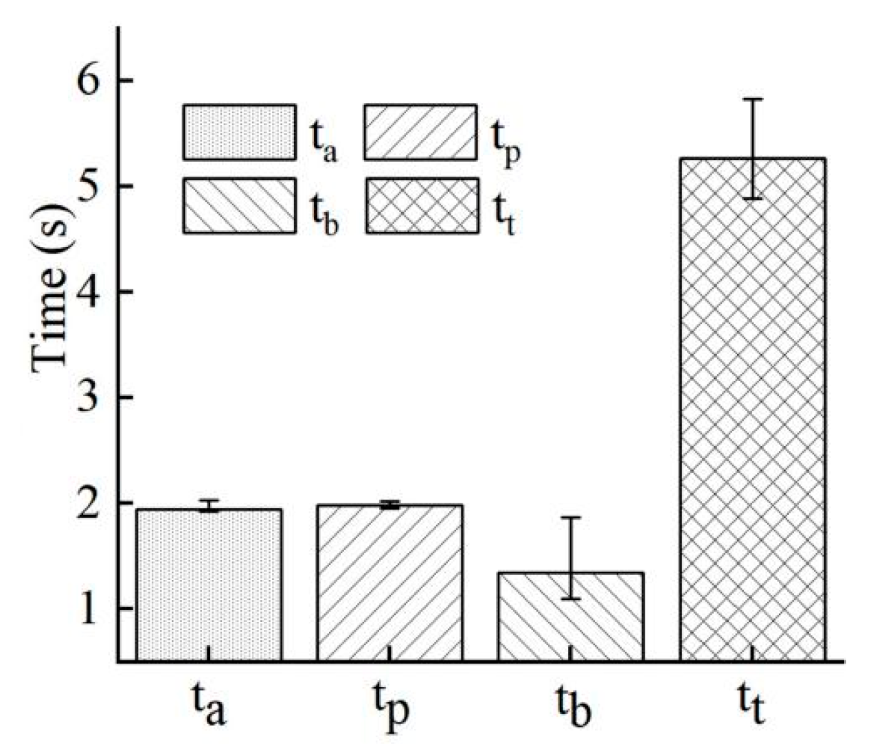
The time distribution for each harvesting cycle stage is shown in Figure 19. The single-fruit picking cycle time comprises the manipulator’s approach time, end-effector’s fruit detachment time, and return time to the collection point. Approaching the fruit took 1.94 ± 0.07 s, detaching the fruit took 1.99 ± 0.02 s, and returning to the collection point took 1.35 ± 0.32 s, resulting in a single-fruit picking cycle time of 5.27 ± 0.34 s. On the laptop, single-image recognition, fruit localization, and picking sequence planning required 0.048 ± 0.010 s. In these harvesting tests, after single-image recognition, all fruits were localized and a picking sequence was planned; the system then continuously harvested all reachable fruits. A new image was acquired only after all fruits in the current sequence were harvested. Therefore, single-image recognition, localization, and sequence planning time was not included in the single-fruit picking cycle time.
Figure 19.
Manipulator harvesting execution time. Note: Error bars represent the standard deviation (SD). ta is the time it takes for the manipulator to approach the fruit, tp is the time it takes to separate the fruit, tb is the time it takes for the manipulator to return to the collection point, and tt is the time it takes to harvest a single fruit.
4. Discussion of Harvesting Trials
The development of apple harvesting robots represents a crucial pathway toward automated harvesting and addressing labor shortages. This research developed three end-effector types—SSE, GSE, and SGSE—and evaluated their harvesting performance using a simplified 4-DoF manipulator in a spindle orchard. Combined with hardware configurations, performance metrics, and experimental conditions from representative studies (Table A1), the following discussion addresses hardware system design, harvesting performance, and horticultural conditions.
Existing research commonly employs manipulators with 4 to 7 DoF to balance flexibility, cost, and control complexity. While high-DoF manipulators, such as the UR5 (6-DoF), offer flexible motion capabilities and a large workspace, they introduce increased system complexity, cost, and energy consumption. Chen’s team (Monash University) utilized a UR5 manipulator, focusing on end-effector improvements and enhanced perception [38,39], achieving a harvesting success rate of 70.77% in 2D planar structured orchards; however, the single-fruit harvesting time was 14.69 s. Considering that in structured or semi-structured orchard environments end-effectors primarily require in-plane approach, rotation, and pull motions, excessive DoF can reduce system response speed and control precision. Consequently, Lu’s team (Michigan State University) developed a PRR manipulator, and Li’s team (Beijing Academy of Agriculture and Forestry Sciences) developed a PPP manipulator. However, low-DoF configurations can result in suboptimal grasping postures. Therefore, Zhang’s team adopted 5-DoF configurations (RPPRR and PPP + RRR) to enhance flexibility in adjusting end-effector orientation. The 4-DoF (PRRP) manipulator used in this study represents an improvement over the previous generation [29]. While maintaining essential motion capabilities, it achieves yaw and pitch control through closed-loop stepper motor drives and a differential gear mechanism. The single-fruit picking cycle time was 5.27 ± 0.34 s. Although this represents an increase of approximately 1 s compared to the previous generation, it remains competitive with other single-arm systems (Liu et al., 2025 [30]: 6.8 s; Huang et al., 2024 [40]: 7.29 s; Zhang et al., 2023 [27]: 6 s). Regarding development cost, the hardware cost of a single improved 4-DoF manipulator arm is approximately $833, covering structural components, closed-loop stepper motors, the differential gear mechanism, and the motor driver board. This represents a 60% reduction from the previous generation ($2067 per arm) and a 29% reduction compared to the single-arm cost reported by Liu et al. (2025) ($1173) [30]. The cost reduction is primarily attributable to replacing two servo motors with a differential gear mechanism. It should be noted that the $833 figure covers the manipulator arm only; costs for the end-effector, stereo camera, computing unit, and mobile platform are additional. Dual-arm or multi-arm configurations represent a significant pathway for improving harvesting efficiency. Compared to single-arm systems, dual-arm configurations enable zoned collaborative operation. However, Liu et al. (2025) [30] reported that the dual-arm system success rate (52.5%) was lower than single-arm performance (60.5%), potentially due to spatial interference between manipulators and increased difficulty in synchronized visual perception. The dual-arm system in this study features vertically staggered installation for zoned harvesting, avoiding workspace overlap; however, this arrangement carries potential risk of missed picks.
End-effectors exhibit an evolutionary trend from rigid grippers toward flexible designs. Early three-finger grippers, while providing stable mechanical grasping, demonstrated limited adaptability to variations in fruit size and shape. Negative-pressure suction technology offers a novel solution for fruit harvesting. Lu’s team, Zhang’s team, and our prior work have employed negative-pressure suction-type end-effectors, achieving minimal-contact grasping that potentially reduces physical damage to fruit. However, this study’s comparative analysis highlights limitations of purely suction-based end-effectors—their high sensitivity to longitudinal positional errors resulted in a harvesting success rate of only 49.21% in the spindle orchard. Under the specific conditions of this study (8-year-old ‘Yanfu’ apple, spindle training system), the GSE achieved a full-process success rate of 61.59%. This value is numerically comparable to results reported by Lammers et al. (2024, 59.90%) [41] and Liu et al. (2025, 60.5%) [30]. This advantage is primarily attributed to the GSE’s superior positional tolerance, which effectively compensates for cumulative errors from visual localization and mechanical motion.
Regarding perception hardware, RGB-D cameras have become the mainstream choice due to their low cost and ease of use, with the Intel RealSense D435/D435i (RealSense, Inc., Santa Clara, CA, USA,) widely adopted. However, RGB-D cameras exhibit limited depth measurement accuracy under strong lighting, long distances, and dense foliage occlusion. To improve localization accuracy, Lu’s team employed an active laser scanner at the cost of increased system complexity and longer detection time (1.1–2.1 s). This study utilizes a ZED stereo camera coupled with a stereo vision system based on the lightweight deep learning network Lad-YXNet, achieving 86.11% orchard recognition accuracy with a processing speed of 0.048 ± 0.010 s. Despite this, a significant gap remains compared to the 100% recognition rate reported under V-trellis systems [26]. Stereo vision systems rely on identifying corresponding feature points between images for triangulation. When target surfaces lack distinct texture (e.g., the high uniformity of apple skin), distance is excessive resulting in reduced disparity, or occlusion limits viewing angles, matching can generate false matches or fail to identify sufficient corresponding points. Even with successful point cloud generation, density may be insufficient under long-distance or occluded conditions to accurately determine fruit position, leading to excessive localization error. In this study, 43 fruits (24.57% of unsuccessfully located fruits) could not be localized due to poor point cloud quality. Furthermore, determining the relative pose between fruit and branch using limited environmental point cloud data, and subsequently predicting optimal picking points and gripper orientation, is crucial for improving success rates. In field conditions, fruit positions may shift during harvesting. When harvesting multiple fruits from the same branch, branch bending decreases as fruit count reduces, causing positional shifts in remaining fruits. Liu et al. (2025) [30] demonstrated that wind-induced fruit oscillation significantly reduces harvesting success rates (from 60.5% to 43.3%). Therefore, repeated fruit detection and localization during continuous harvesting, or integration of additional localization sensors on the end-effector, is necessary to compensate for localization errors. The harvesting system in this study did not incorporate visual servo feedback. While meeting basic precision requirements, overall robustness remains insufficient, consequently affecting the harvesting success rate.
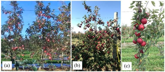
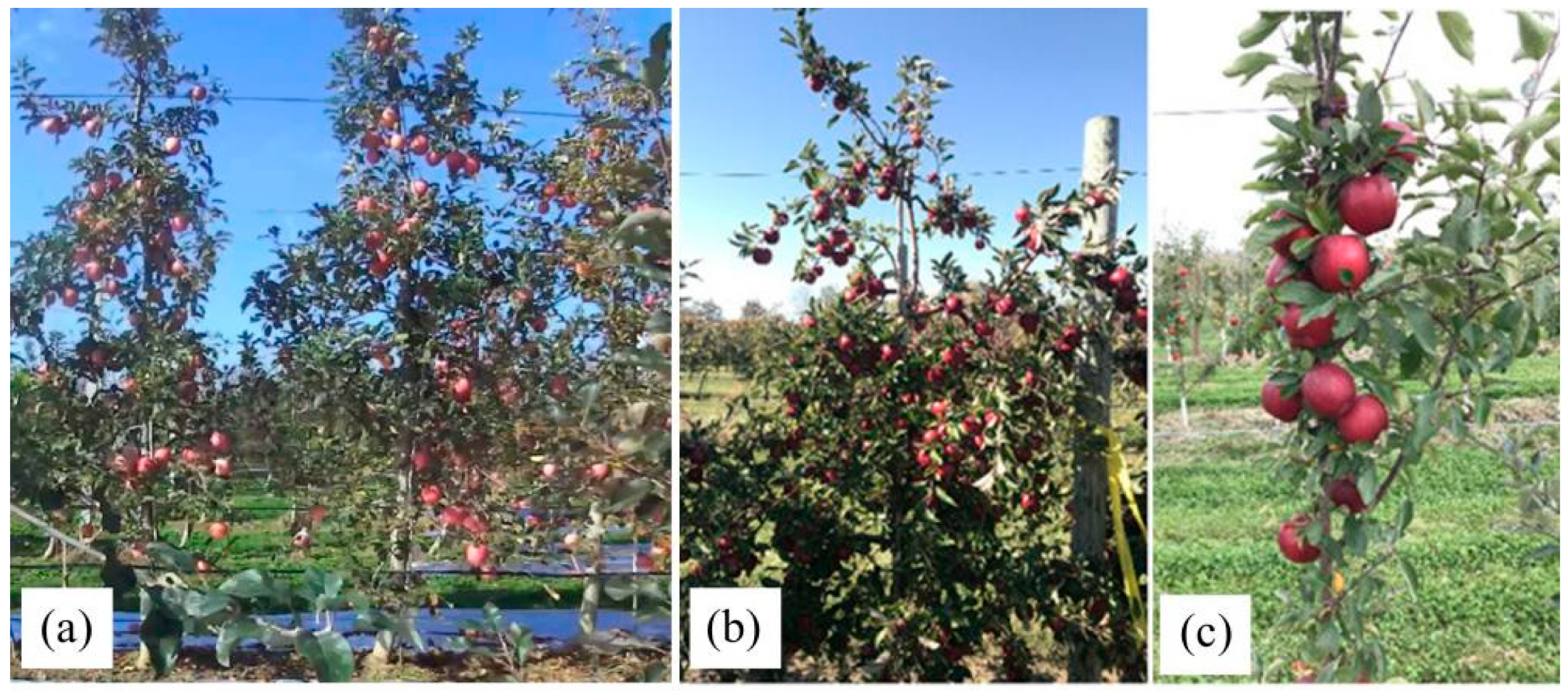
Orchard cultivation architecture, tree age, cultivar, and fruit distribution characteristics may play a more decisive role in harvesting robot performance. This study achieved a 61.59% harvesting success rate in an 8-year-old ‘Yanfu’ apple orchard with spindle architecture (Figure 20a). Comparison with other research teams under different horticultural conditions highlights the critical influence of environmental factors. Karkee’s team (Washington State University) pioneered harvesting robot research in modern high-density cultivation systems such as V-trellis [26] and fruit wall [42] orchards (Figure 20d), achieving an 84.60% success rate. In our team’s prior research using a 6-DoF industrial manipulator in a simulated fruit wall orchard, an 82.19% success rate was attained, albeit with longer cycle time [43]. Cultivation systems like V-trellis and fruit walls, characterized by standardized tree architecture and regularized fruit distribution, provide favorable environments for robotic operation. For other fruits and vegetables, modifying the crop environment through pruning to simplify robotic tasks represents an important approach for improving success rates. The harvesting success rate for sweet peppers increased from 6% to 26% after pruning [44], and for strawberries from 53.6% to 96.8% [45]. Although pruning and standardized tree architectures can enhance robotic harvesting success, associated costs and economic trade-offs have not been fully justified in commercial settings.
Figure 20.
Field experiment scene. (a) 8-year-old ‘Yanfu’ spindle. (b) 7-year-old ‘Ida Red’ [27]. (c) 2-year-old ‘Gala’ [27].
Tree age also influences harvesting performance. Zhang et al. (2023) [27] demonstrated that the harvesting success rate for 2-year-old trees (Figure 20c) was significantly higher (82.4%) than for 7-year-old trees (Figure 20b) (65.2%), indicating a negative correlation between tree structural complexity and ease of robotic harvesting. Li et al. (2023) [46] conducted a statistical analysis of fruit occlusion levels prior to harvesting experiments, finding that only 38% of fruits were unobstructed while 36% experienced moderate or severe occlusion (Figure 20e). Their system achieved collaborative four-arm harvesting success rates of 71.28% to 80.45%.
Picking actions and gripping control can cause varying degrees of fruit damage. Differences among apple cultivars in fruit size, shape, and stem strength are significant factors directly influencing damage risk. Reported fruit damage rates vary considerably across cultivars: Silwal et al. (2017) [26] reported 6.3% stem loss for ‘Envy’ apples; Zhang et al. (2023) [27] reported 20.8% stem loss and 11.0% puncture damage for ‘Gala’ and ‘Ida Red’ apples; Liu et al. (2025) [30] reported approximately 7% bruising and 23.8–29% stem pulled for ‘Fuji’ apples. In this study, overall fruit damage rate (including stem pulled and body bruising) for mature 8-year-old ‘Yanfu’ apples ranged from 10.89% to 13.33%. Designing appropriate picking strategies tailored to specific cultivars, or mimicking human picking motions, represents a potential pathway for reducing stem pulled rates.
In summary, apple harvesting robots face numerous technical challenges regarding success rate, efficiency, fruit damage, and adaptability to complex tree architectures. Through field trials in an 8-year-old spindle orchard, this study comparatively analyzed harvesting performance of three negative-pressure driven soft end-effectors. Results demonstrate positional tolerance of the end-effector is a more decisive factor for harvesting success than functional complexity; the GSE’s ability to establish secure grasps despite cumulative localization errors proved more effective than the SGSE. Simplified manipulator architectures (4-DoF) can achieve competitive cycle times and success rates in semi-structured orchard environments, provided that the end-effector compensates for the limited degrees of freedom through inherent adaptability. A zoned multi-manipulator strategy with vertically staggered installation offers a practical pathway for scaling coverage without incurring the control complexity of overlapping workspaces. However, this study also reveals limitations of the 4-DoF manipulator in workspace coverage and complex posture adjustment. The detailed analysis of harvesting failures and stage-by-stage performance evaluation provide clear directions for subsequent optimization.
5. Future Work
Although the apple harvesting robot developed in this study was successfully tested in a spindle orchard, validating the feasibility and performance of the simplified 4-DoF multi-manipulator configuration and three end-effector designs, the overall system remains at prototype stage. Key aspects requiring further development include coordinated multi-manipulator motion planning, precise fruit-and-branch pose perception, and integration of downstream post-harvest processes such as transport, sorting, grading, and packaging. Additionally, extensive testing across diverse tree architectures, cultivars, and fruit varieties is necessary.
Future work will focus on: (1) investigating mechanical interactions between the end-effector and fruit-branch system to enable co-optimization of tree architecture and robotic harvesting strategies; (2) integrating post-harvest handling technologies to develop a cohesive system encompassing harvesting, collection, transport, and sorting; (3) implementing advanced control and planning strategies, including visual servo closed-loop control, coordinated multi-manipulator operation, and human–robot collaborative harvesting; (4) developing scene-aware robotic decision-making that enables the system to perceive local growing context, predict consequences of detachment patterns on neighboring fruits, and autonomously plan optimal picking sequences.
6. Conclusions
This study developed an integrated apple harvesting robot featuring machine vision, flexible end-effectors, a simplified 4-DoF manipulator, and a mobile chassis, demonstrating functional automated harvesting. A comparative field evaluation of three end-effector types (SSE, GSE, SGSE) was performed using a simplified 4-DoF manipulator. The key findings are summarized as follows:
- (1)
- The pitch and yaw motions of the harvesting manipulator were realized through a differential mechanism. Trajectory planning employing linear interpolation with a harmonic acceleration/deceleration profile ensured continuous velocity and acceleration curves for the end-effector, thereby enhancing motion smoothness. The hand-eye calibration achieved a mean positional error of 4.7 ± 2.7 mm.
- (2)
- The fruit harvesting success rates for the three end-effector types (SSE, GSE, and SGSE) were 49.21%, 80.80%, and 64.71%, respectively, with corresponding overall fruit damage rates of 12.90%, 10.89%, and 13.33%. The full-process (from detection to collection) harvesting success rate for the GSE was 61.59%, and the single-fruit harvesting cycle time was 5.27 ± 0.34 s.
Author Contributions
Writing—Original Draft, G.H.; Writing—Review and Editing, J.C.; Methodology: G.H. and J.C.; Conceptualization, G.H. and S.W.; Software, G.H. and J.Z.; Investigation: S.W., C.C., F.C. and Y.C.; Visualization, N.C.; Resources, Y.C. and J.C.; Supervision, F.C.; Founding acquisition: G.H. and J.C. All authors have read and agreed to the published version of the manuscript.
Funding
This research was funded by the Young Talent Fund of Xi’an Association for Science and Technology (grant number 0959202513126), the National Natural Science Foundation of China (grant number 32272001), the Qinchuangyuan Project of Shaanxi Province (grant number 2023KXJ-016), the Xianyang “Scientists + Engineers” Team Project (grant number L2024-CXNL-KJRCTD-DWJS-0002).
Data Availability Statement
The data presented in this study is available on request from the corresponding author.
Acknowledgments
This study was supported by the Young Talent Fund of Xi’an Association for Science and Technology (No. 0959202513126), the National Natural Science Foundation of China (No. 32272001), the Qinchuangyuan Project of Shaanxi Province (No. 2023KXJ-016), the Xianyang “Scientists + Engineers” Team Project (No. L2024-CXNL-KJRCTD-DWJS-0002). The authors sincerely acknowledge the members of the research team for their help.
Conflicts of Interest
The authors declare no conflicts of interest.
Abbreviations
The following abbreviations are used in this manuscript:
| D–H | Denavit–Hartenberg |
| DoF | Degree of freedom |
| GSE | Gripping soft end-effector |
| Lad-YXNet | Lightweight Apple Detection YOLOX-Tiny Network |
| R-CNN | Region-based Convolutional Neural Networks |
| SGSE | Suction-gripping soft end-effector |
| SSD | Single Shot MultiBox Detector |
| SSE | Suction soft end effector |
| YOLO | You Only Look Once |
Appendix A
Table A1.
Comparison of this research and existing apple harvesting robots.
References
- Vrochidou, E.; Tsakalidou, V.N.; Kalathas, I.; Gkrimpizis, T.; Pachidis, T.; Kaburlasos, V.G. An overview of end effectors in agricultural robotic harvesting systems. Agriculture 2022, 12, 1240. [Google Scholar] [CrossRef] [Scilit]
- Zhang, B.; Xie, Y.; Zhou, J.; Wang, K.; Zhang, Z. State-of-the-art robotic grippers, grasping and control strategies, as well as their applications in agricultural robots: A review. Comput. Electron. Agric. 2020, 177, 105694. [Google Scholar] [CrossRef] [Scilit]
- Hua, W.; Zhang, Z.; Zhang, W.; Liu, X.; Hu, C.; He, Y.; Mhamed, M.; Li, X.; Dong, H.; Saha, C.K.; et al. Key technologies in apple harvesting robot for standardized orchards: A comprehensive review of innovations, challenges, and future directions. Comput. Electron. Agric. 2025, 235, 110343. [Google Scholar] [CrossRef] [Scilit]
- Rajendran, V.; Debnath, B.; Mghames, S.; Mandil, W.; Parsa, S.; Parsons, S.; Ghalamzan-E, A. Towards autonomous selective harvesting: A review of robot perception, robot design, motion planning and control. J. Field Robot. 2023, 40, 2247–2279. [Google Scholar] [CrossRef] [Scilit]
- Chen, Q.; Yin, C.; Guo, Z.; Wang, J.; Zhou, H.; Jiang, X. Current status and future development of the key technologies for apple picking robots. Trans. Chin. Soc. Agric. Eng. 2023, 38, 1–15. [Google Scholar] [CrossRef]
- Zhang, Z.; Heinemann, P.H.; Liu, J.; Baugher, T.A.; Schupp, J.R. The Development of Mechanical Apple Harvesting Technology: A Review. Trans. ASABE 2016, 59, 1165–1180. [Google Scholar] [CrossRef] [Scilit]
- Bu, L.; Chen, C.; Hu, G.; Sugirbay, A.; Chen, J. Technological Development of Robotic Apple Harvesters: A Review. INMATEH-Agric. Eng. 2020, 61, 151–164. [Google Scholar] [CrossRef] [Scilit]
- Noreen, T.; Ali, A.; Anwar, S.; Farooq, S.; Altabey, W.A.; Kouritem, S.A.; Noori, M. Implementation of fruit plucking robot in apple harvesting: A review. Results Eng. 2025, 27, 106575. [Google Scholar] [CrossRef] [Scilit]
- Zhou, H.; Wang, X.; Au, W.; Kang, H.; Chen, C. Intelligent robots for fruit harvesting: Recent developments and future challenges. Precis. Agric. 2022, 23, 1856–1907. [Google Scholar] [CrossRef] [Scilit]
- Mhamed, M.; Zhang, Z.; Yu, J.; Li, Y.; Zhang, M. Advances in apple’s automated orchard equipment: A comprehensive research. Comput. Electron. Agric. 2024, 221, 108926. [Google Scholar] [CrossRef] [Scilit]
- Liu, J.; Jiang, Y. Industrialization trends and multi-arm technology direction of harvesting robots. Trans. Chin. Soc. Agric. Mach. 2024, 55, 1–17. [Google Scholar] [CrossRef]
- Yuan, J. Research progress analysis of robotics selective harvesting technologies. Trans. Chin. Soc. Agric. Mach. 2020, 51, 1–17. [Google Scholar] [CrossRef]
- Zhang, Y.; Li, N.; Zhang, L.; Lin, J.; Gao, X.; Chen, G. A review on the recent developments in vision-based apple-harvesting robots for recognizing fruit and picking pose. Comput. Electron. Agric. 2025, 231, 109968. [Google Scholar] [CrossRef] [Scilit]
- Jin, Y.; Xia, X.; Gao, Q.; Yue, Y.; Lim, E.G.; Wong, P.; Ding, W.; Zhu, X. Deep learning in produce perception of harvesting robots: A comprehensive review. Appl. Soft Comput. 2025, 174, 112971. [Google Scholar] [CrossRef] [Scilit]
- Zhang, Y.; Li, L.; Chun, C.; Wen, Y.; Xu, G. Multi-scale feature adaptive fusion model for real-time detection in complex citrus orchard environments. Comput. Electron. Agric. 2024, 219, 108836. [Google Scholar] [CrossRef] [Scilit]
- Kok, E.; Chen, C. Occluded apples orientation estimator based on deep learning model for robotic harvesting. Comput. Electron. Agric. 2024, 219, 108781. [Google Scholar] [CrossRef] [Scilit]
- Mirbod, O.; Choi, D.; Heinemann, P.H.; Marini, R.P.; He, L. On-tree apple fruit size estimation using stereo vision with deep learning-based occlusion handling. Biosyst. Eng. 2023, 226, 27–42. [Google Scholar] [CrossRef] [Scilit]
- Miranda, J.C.; Arnó, J.; Gené-Mola, J.; Lordan, J.; Asín, L.; Gregorio, E. Assessing automatic data processing algorithms for RGB-D cameras to predict fruit size and weight in apples. Comput. Electron. Agric. 2023, 214, 108302. [Google Scholar] [CrossRef] [Scilit]
- Kang, H.; Wang, X.; Chen, C. Accurate fruit localisation using high resolution LiDAR-camera fusion and instance segmentation. Comput. Electron. Agric. 2022, 203, 107450. [Google Scholar] [CrossRef] [Scilit]
- Yang, X.; Zhong, J.; Lin, K.; Wu, J.; Chen, J.; Si, H. Research progress on binocular stereo vision technology and its applications in smart agriculture. Trans. Chin. Soc. Agric. Eng. 2025, 41, 27–39. [Google Scholar] [CrossRef]
- Seo, D.; Lee, S.K.; Kim, J.G.; Oh, I.-S. High-precision peach fruit segmentation under adverse conditions using Swin Transformer. Agriculture 2024, 14, 903. [Google Scholar] [CrossRef] [Scilit]
- Yang, Y.; Han, Y.; Li, S.; Yang, Y.; Zhang, M.; Li, H. Vision based fruit recognition and positioning technology for harvesting robots. Comput. Electron. Agric. 2023, 213, 108258. [Google Scholar] [CrossRef] [Scilit]
- Montoya-Cavero, L.-E.; Díaz de León Torres, R.; Gómez-Espinosa, A.; Escobedo Cabello, J.A. Vision systems for harvesting robots: Produce detection and localization. Comput. Electron. Agric. 2022, 192, 106562. [Google Scholar] [CrossRef] [Scilit]
- Hu, G.; Zhou, J.; Chen, C.; Li, C.; Sun, L.; Chen, Y.; Zhang, S.; Chen, J. Fusion of the lightweight network and visual attention mechanism to detect apples in orchard environment. Trans. CSAE 2022, 38, 131–142. [Google Scholar] [CrossRef]
- Wen, S.; Ge, Y.; Wang, Y.; Wei, N.; Zhou, J.; Hu, G.; Yang, L.; Chen, J. Efficient and comprehensive visual solution for a smart apple harvesting robot in complex settings via multi-class instance segmentation. Int. J. Agric. Biol. Eng. 2025, 18, 200–215. [Google Scholar] [CrossRef] [Scilit]
- Silwal, A.; Davidson, J.R.; Karkee, M.; Mo, C.; Zhang, Q.; Lewis, K. Design, integration, and field evaluation of a robotic apple harvester. J. Field Robot. 2017, 34, 1140–1159. [Google Scholar] [CrossRef] [Scilit]
- Zhang, K.; Lammers, K.; Chu, P.; Li, Z.; Lu, R. An automated apple harvesting robot—From system design to field evaluation. J. Field Robot. 2023, 41, 2384–2400. [Google Scholar] [CrossRef] [Scilit]
- Feng, Q.; Zhao, C.; Li, T.; Chen, L.; Guo, X.; Xie, F.; Xiong, Z.; Chen, K.; Liu, C.; Yan, T. Design and test of a four-arm apple harvesting robot. Trans. Chin. Soc. Agric. Eng. 2023, 39, 25–33. [Google Scholar] [CrossRef]
- Hu, G.; Chen, C.; Chen, J.; Sun, L.; Sugirbay, A.; Chen, Y.; Jin, H.; Zhang, S.; Bu, L. Simplified 4-DOF manipulator for rapid robotic apple harvesting. Comput. Electron. Agric. 2022, 199, 107177. [Google Scholar] [CrossRef] [Scilit]
- Liu, X.; Zhang, Z.; Yu, J.; Hua, W.; Li, X.; Azizi, A.; Mhamed, M.; Abid, F.; Abdelhamid, M.A. Design, integration, and evaluation of a low-cost system for automatic apple picking and infield sorting. Comput. Electron. Agric. 2025, 239, 110933. [Google Scholar] [CrossRef] [Scilit]
- Hua, W.; Zhang, W.; Zhang, Z.; Liu, X.; Huang, M.; Igathinathane, C.; Vougioukas, S.; Saha, C.K.; Mustafa, N.S.; Salama, D.S.; et al. Vacuum suction end-effector development for robotic harvesters of fresh market apples. Biosyst. Eng. 2025, 249, 28–40. [Google Scholar] [CrossRef] [Scilit]
- Zhang, K.; Lammers, K.; Chu, P.; Li, Z.; Lu, R. System design and control of an apple harvesting robot. Mechatronics 2021, 79, 102644. [Google Scholar] [CrossRef] [Scilit]
- Wang, X.; Kang, H.; Zhou, H.; Au, W.; Wang, M.Y.; Chen, C. Development and evaluation of a robust soft robotic gripper for apple harvesting. Comput. Electron. Agric. 2023, 204, 107552. [Google Scholar] [CrossRef] [Scilit]
- Elfferich, J.F.; Dodou, D.; Santina, C.D. Soft Robotic Grippers for Crop Handling or Harvesting: A Review. IEEE Access 2022, 10, 75428–75443. [Google Scholar] [CrossRef] [Scilit]
- Zhang, Z.; Igathinathane, C.; Li, J.; Cen, H.; Lu, Y.; Flores, P. Technology progress in mechanical harvest of fresh market apples. Comput. Electron. Agric. 2020, 175, 105606. [Google Scholar] [CrossRef] [Scilit]
- Fan, P.; Yan, B.; Wang, M.; Lei, X.; Liu, Z.; Yang, F. Three-finger grasp planning and experimental analysis of picking patterns for robotic apple harvesting. Comput. Electron. Agric. 2021, 188, 106353. [Google Scholar] [CrossRef] [Scilit]
- Lu, L. Dropping bruise fragilities and bruise boundaries of ‘Gala’ apples. Trans. CSAE 2008, 24, 37–43. [Google Scholar]
- Kang, H.; Zhou, H.; Wang, X.; Chen, C. Real-Time Fruit Recognition and Grasping Estimation for Robotic Apple Harvesting. Sensors 2020, 20, 5670. [Google Scholar] [CrossRef] [Scilit]
- Wang, X.; Kang, H.; Zhou, H.; Au, W.; Chen, C. Geometry-aware fruit grasping estimation for robotic harvesting in apple orchards. Comput. Electron. Agric. 2022, 193, 106716. [Google Scholar] [CrossRef] [Scilit]
- Huang, W.; Miao, Z.; Wu, T.; Guo, Z.; Han, W.; Li, T. Design of and Experiment with a Dual-Arm Apple Harvesting Robot System. Horticulturae 2024, 10, 1268. [Google Scholar] [CrossRef] [Scilit]
- Lammers, K.; Zhang, K.; Zhu, K.; Chu, P.; Li, Z.; Lu, R. Development and evaluation of a dual-arm robotic apple harvesting system. Comput. Electron. Agric. 2024, 227, 109586. [Google Scholar] [CrossRef] [Scilit]
- Hohimer, C.J.; Wang, H.; Bhusal, S.; Miller, J.; Mo, C.; Karkee, M. Design and Field Evaluation of a Robotic Apple Harvesting System with a 3D-Printed Soft-Robotic End-Effector. Trans. ASABE 2019, 62, 405–414. [Google Scholar] [CrossRef] [Scilit]
- Bu, L.; Chen, C.; Hu, G.; Sugirbay, A.; Sun, H.; Chen, J. Design and evaluation of a robotic apple harvester using optimized picking patterns. Comput. Electron. Agric. 2022, 198, 107092. [Google Scholar] [CrossRef] [Scilit]
- Bac, C.W.; Hemming, J.; van Tuijl, B.A.J.; Barth, R.; Wais, E.; van Henten, E.J. Performance evaluation of a harvesting robot for sweet pepper. J. Field Robot. 2017, 34, 1123–1139. [Google Scholar] [CrossRef] [Scilit]
- Xiong, Y.; Peng, C.; Grimstad, L.; From, P.J.; Isler, V. Development and field evaluation of a strawberry harvesting robot with a cable-driven gripper. Comput. Electron. Agric. 2019, 157, 392–402. [Google Scholar] [CrossRef] [Scilit]
- Li, T.; Xie, F.; Zhao, Z.; Zhao, H.; Guo, X.; Feng, Q. A multi-arm robot system for efficient apple harvesting: Perception, task plan and control. Comput. Electron. Agric. 2023, 211, 107979. [Google Scholar] [CrossRef] [Scilit]

Disclaimer/Publisher’s Note: The statements, opinions and data contained in all publications are solely those of the individual author(s) and contributor(s) and not of MDPI and/or the editor(s). MDPI and/or the editor(s) disclaim responsibility for any injury to people or property resulting from any ideas, methods, instructions or products referred to in the content. |
© 2026 by the authors. Licensee MDPI, Basel, Switzerland. This article is an open access article distributed under the terms and conditions of the Creative Commons Attribution (CC BY) license.