


Abstract
To address the existing problems of frequent manual tray handling, poor continuity, and insufficient coordination in fully automatic transplanters, this study designed an integrated multi-layer tray-handling and dual-claw coordinated seedling pick-and-throw mechanism. Through continuous tray conveying and multi-layer tray-handling mechanisms, automatic replacement of multiple seedling trays was achieved. A dual-claw coordinated seedling picking and planting mechanism was designed, and the seedling picking trajectory was optimized based on path planning and RecurDyn kinematic simulation. Six-segment and seven-segment S-shaped acceleration and deceleration motion control curves and planning strategies that can be switched according to the target displacement and dynamic parameters were proposed, and a PLC-based software and hardware control system was constructed. The simulation and experimental results show that the dual-module parallel motion mode is more efficient and has a smoother trajectory than the serial mode. The average positioning absolute error of tray conveying is 1.09 mm, the average horizontal and vertical positioning absolute errors of seedling picking are 1.07 mm and 1.09 mm, respectively, and the horizontal and vertical positioning absolute errors of seedling planting are 1.50 mm and 1.51 mm, respectively. The success rate of seedling picking is 97.01%, the success rate of seedling planting is 96.39%, and the qualified rate of planting is 96%. The experimental results meet the actual operation requirements. This study provides a theoretical basis and technical support for the high-efficiency coordinated operation of fully automatic transplanters.
1. Introduction
Vegetable production constitutes a vital component of global agriculture, where mechanized cultivation plays a pivotal role in safeguarding food security [1,2]. Automated transplanting technology, as a critical component of modern vegetable production systems, has demonstrated significant potential in addressing persistent challenges such as labor scarcity and suboptimal operational efficiency [3]. However, the existing fully automatic transplanting machines still have two major technical bottlenecks [4]: the supply of seedling trays still relies on manual labor, and the continuity of seedling tray conveying is poor. At the same time, the complex procedures in the seedling picking and conveying mechanism and the insufficient stability of the movement result in a high rate of seedling injuries [5]. These constraints represent substantial barriers to achieving truly autonomous, high-precision transplanting systems.
The automatic tray-conveying mechanisms in countries such as Europe, America and Japan all have integrated application structures [6]. The three-row fully automatic tomato transplanter in Belgium [7] is equipped with a horizontal conveyor belt mechanism to convey the seedling trays. When performing continuous tray supply operations, it is frequently necessary to place the seedling trays on the belt manually. Moreover, the seedling trays are specially made foam trays, which are prone to damage. The seedling tray supply mechanism of the Italian FUTURA transplanter [8] is similar to that of the PF2R dual-row fully automatic transplanter (Yanma, Japan). It adopts an inclined conveying mechanism, and the seedling trays move longitudinally and laterally intermittently with mechanical positioning [9]. Manual replacement of the seedling trays is still required when one or two seedling trays are placed each time. Chinese researchers have conducted some studies [10]. A transplant device for pepper seedlings with a five-bar fixed-axis gear train picking mechanism [11] was designed, and a guide rail lead screw mechanism was used to carry the seedling tray transversely. The seedling tray-conveying mechanism [12] adopts a horizontal tray-conveying method. The seedling trays are manually placed on the designated horizontal pull-rod support plate, and the chain drives the pull rod for conveying. This mechanism is relatively long in shape and complex in structure. An automatic seedling tray-conveying device that operates on a horizontal conveying platform to achieve the precise positioning and conveying of seedling trays was designed [13]. A seedling delivery device that has two seedling tray supply devices placed at an angle and symmetrically, sharing one set of drive devices, was developed [14]. However, each supply device can only deliver one tray at a time, and the empty trays are prone to damage when being retrieved.
All of the designs studied above can place one or two trays at a time. When operating continuously, manual continuous tray placement is required. To solve this problem, a mechanism which can transport four trays of seedlings in one cycle was designed [15]; it achieves intermittent descent and layer-by-layer positioning push through three chain drive mechanisms. The seedling trays in another mechanism [16] slide onto the horizontal conveying mechanism by their own gravity and inclination angle, but there can be situations where the positions of the seedling trays shift. At the same time, there can be a problem where the front and rear seedling trays are superimposed and interlaced due to a failure to replace them in a timely manner. The most of the studied devices have large and complex structures and have not been put into practical production use [17,18]. There is still a lack of streamlined continuous automatic tray-conveying devices.
As one of the core technologies of fully automatic transplanters, the technology of picking and throwing seedlings has been extensively studied [19,20]. The Dutch PC-21 fully automatic transplanter adopts an end-effector with a two-claw and four-needle design for picking up seedlings [21] and is powered by a cylinder and a motor. The cylinder is responsible for picking up and releasing the seedlings and electro-hydraulic integrated technology is used to pick up multiple seedlings at one time. However, it is relatively large in size and has a high cost. The gear-connecting-rod-type [22] seedling picking and throwing mechanism in the Japanese transplanter realizes single-arm reciprocating seedling picking action through the gear-connecting rod. The clamp-on seedling picking method has strong reliability in picking, but the seedling picking claws are inserted into the pot body from the top of the pot when picking, which may cause damage to the seedlings and the pot. Chen designed an elliptical incomplete non-circular-gear-type seedling picking and throwing mechanism [23]. The end actuator not only moves in a uniform circular motion along with the planetary gearbox, but also moves in a non-uniform intermittent motion along with the planetary gear shaft relative to the box. Under these two compound motions seedling picking and pushing actions are achieved, although these two types of mechanisms are purely mechanical structures that are complex in structure and it is not easy to control their speed and positioning accuracy. The above two mechanisms adopt a purely mechanical structure, which has high requirements for processing accuracy and synchronization with other mechanisms [24]. Moreover, it is difficult to control the speed of picking and conveying seedlings, and the positioning accuracy is unstable. Wang Xiu developed a stem-clamping-type seedling picking mechanism suitable for vegetable transplanting. By clamping the seedling stems, the potted seedlings are separated from the trays, and then six seedling picking claws are evenly distributed and planted through a pneumatic seedling distribution device. The entire process involves rather complex operation procedures, and using this method for picking seedlings with interlaced stems will have an impact on the growth of the seedlings.
In the above research, the mechanical structure is complex and it is not easy to control the operation speed and accuracy. In addition, the process of picking and transplanting seedlings is rather complicated and cumbersome. It requires the operation of a seedling separation device before the transplanting and planting operations are carried out, which affects the efficiency of the transplanting operation. The top-clamping and pull-out combined seedling picking and throwing mechanism developed by Jianping Hu [25] can take seedlings at intervals in a row, allowing for the picking of six seedling pots at a time. The flipping mechanism swings to pick up the seedlings. The seedling pushing mechanism on the back and the insertion and pulling mechanism on the front move simultaneously, pushing out the seedlings in the bowl and completing the picking action at the same time. When this device is in operation, it is difficult to control the movement speed. When the pot seedlings are pushed out, the pot body is prone to damage. Another device was designed [26] to decrease the damage during the picking process, with cooperative operation between seedling conveying and picking, although it still needs a separating device for the seedlings and there is no tray-handling device.
To address the limitations of current vegetable transplanters, particularly the dependence on frequent manual tray replenishment and the limited continuity of tray handling, this study proposes the development of an automated tray supply mechanism integrating tray handling, conveying, and recycling functions. Aiming at solving the problems of cumbersome procedures and the poor positioning accuracy of the seedling picking and throwing mechanism, a dual-claw cooperative seedling picking and conveying mechanism is proposed. Based on this structure, the movement path and strategy of seedling picking and conveying are optimized, and an S-shaped acceleration and deceleration control model is adopted to achieve a smooth speed transition.
2. Materials and Methods
2.1. Design of the Structure and Key Components
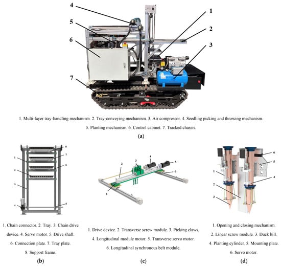
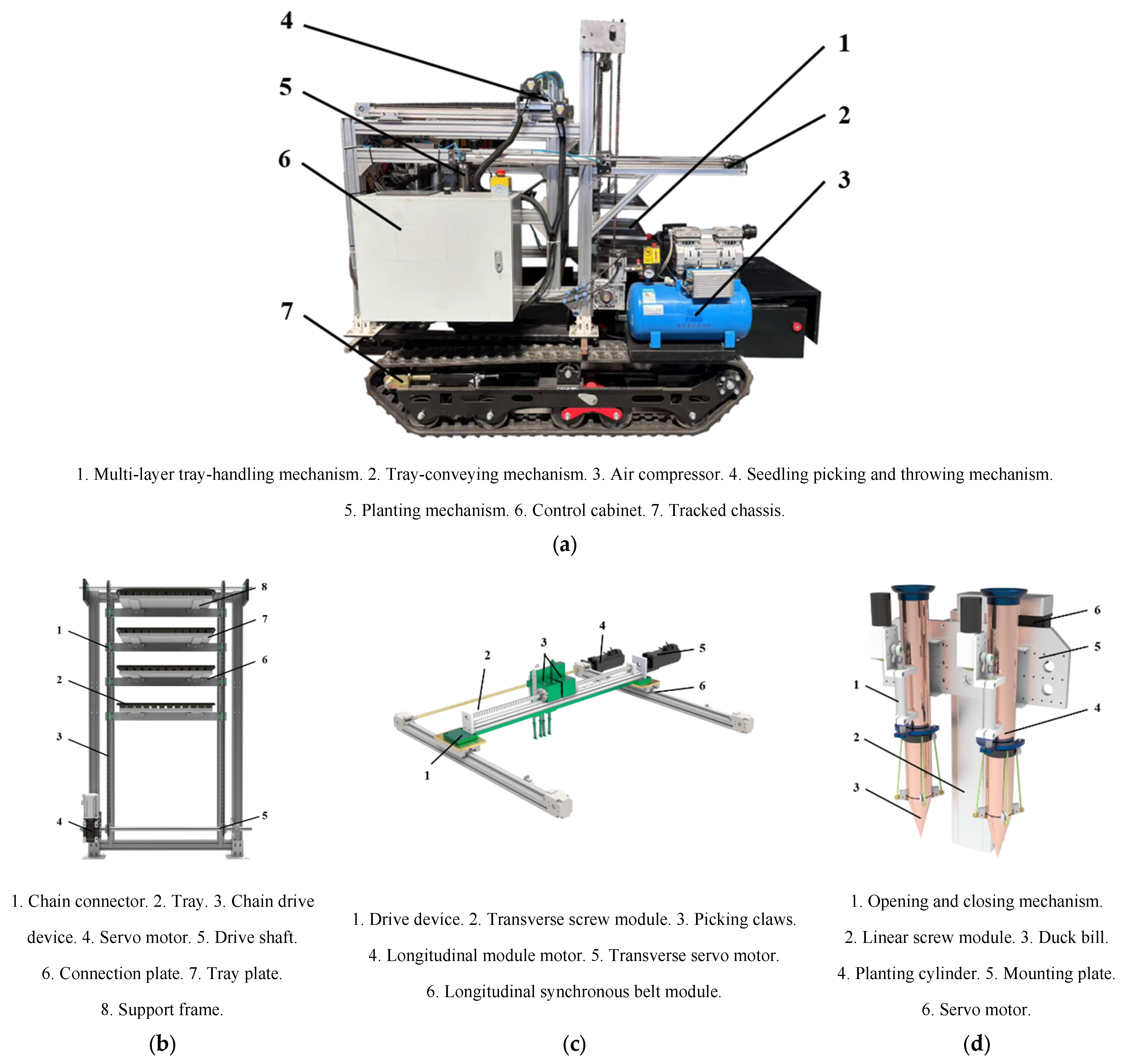
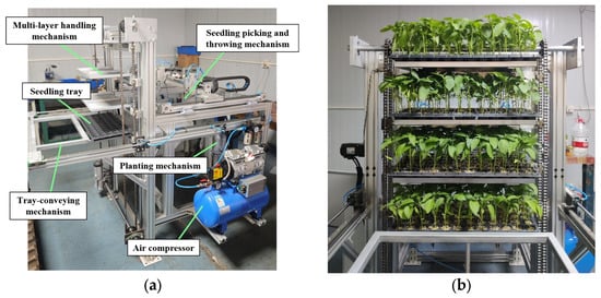
The machine consists of a multi-layer tray-handling mechanism, a tray-conveying mechanism, a seedling picking and throwing mechanism, a planting mechanism, a tracked chassis, and a control cabinet, as shown in Figure 1a. Additionally, its multi-layer tray-handling mechanism eliminates the need for manual tray replenishment, at least while working on a single ridge, making it a key component in achieving unmanned transplanting operations.
Figure 1.
Overall schematic diagram of the machine: (a) the structure of whole machine; (b) the handling mechanism; (c) the seedling picking mechanism; (d) the planting mechanism.
2.1.1. Multi-Layer Tray-Handling Mechanism
The multi-layer tray-handling mechanism mainly consists of a servo motor, a reducer, a four-layer pallet, and a chain drive device, as shown in Figure 1b. Among them, the pallet is composed of a layer board, support frame, connection plate, and limit strip. A single pallet is connected with the self-aligning ball rail (SBR) linear guide slide block symmetrically mounted on the frame through the connecting plate of the support frame, and the slide block on the SBR linear guide drives the seedling tray-handling device to move up and down. The whole device is driven by the power system composed of a servo motor and a reducer, which can realize continuous tray handling and conveying.
The tray used has 72 holes and can cultivate a variety of different vegetables such as peppers, tomatoes, cucumbers, etc., and the average height of seedlings before transplanting was between 150 mm and 180 mm [27], so the spacing distance of each pallet was set at 170 mm. The more pallets, the higher the device, so the number of pallets is set as four in this mechanism and the total weight of the device with the trays and seedlings is 24 kg.
To make the structure compact and reliable, a single-row chain with a small pitch was selected; a 08B chain with a pitch of = 12.7 mm was used here. According to national standards [28] the parameters of the chain are shown in Table 1.
Table 1.
Parameters of chain.
The driving and driven sprockets should be considered; the number of teeth of the driving sprocket should not be too large, otherwise the number of teeth of the driven sprocket will increase due to the transmission ratio, which will increase the deformation and elongation of the chain pitch, making it easy for the chain to skip teeth or come off. The parameters of the sprocket are shown in Table 2. The sprocket with 19 teeth was selected as the driving sprocket of the roller chain, and the pitch diameter of the sprocket is calculated as follows:
where is the pitch diameter, in mm; is the number of teeth of the sprocket.
Table 2.
Parameters of sprocket.
2.1.2. Dual-Claw Seedling Picking Mechanism
The dual-claw cooperative seedling picking and throwing device is shown in Figure 1c. It mainly includes two end-effectors for picking the seedlings and the actuating device for driving the end-effector. The end-effector comprised a lifting cylinder, a telescopic cylinder, seedling needles, a seedling pushing ring, and a mounting plate. The actuating device consisted of a horizontal positive and negative ball screw module, a transverse servo motor, a vertical synchronous belt linear module, a longitudinal motor, and a mounting plate. With the lateral and longitudinal cooperative movement of two motors, the actuating device drives the end-effector to complete the picking and throwing of the whole tray under dynamic variable distance.
The 72-hole tray is configured with 12 columns along its long side and 6 rows along its wide side. During seedling picking and throwing, the reciprocating motion process along the wide side, defined as the longitudinal direction, is driven by a synchronous belt module. Lateral displacement along the long side, designated as the transverse direction, is actuated by a ball screw module. The zero point of the seedling picking device is the first row and the two symmetrical sides of the columns. Once the seedling tray is conveyed to the picking position, the two end-effectors simultaneously extract two seedlings and transport them to the planting tubes through coordinated transverse and longitudinal module movements. The process repeats until all of the seedlings in the tray have been picked. The key parameters of the synchronous belt linear module and the bidirectional ball screw module are provided in Table 3.
Table 3.
Parameters of transverse and longitudinal driving module.
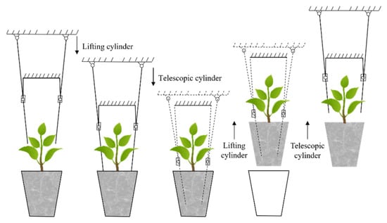
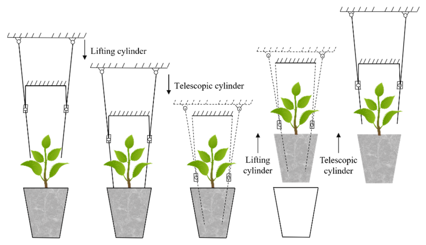
As shown in Figure 2, the lifting cylinder controls the downward movement of the plate until the seedling needles move to the surface of the seedling bowl, then the telescopic cylinder controls the needles downward, inserting them into the seedling bowl so that the needles can hold the seedlings. Moreover, the lifting cylinder drives the upward movement of the plate, and the end-effectors with seedlings will be driven from the picking points to the throwing points. Finally, the seedling can be planted once the needle retracts following the withdrawal of the telescopic cylinder.
Figure 2.
A schematic operation diagram of seedling picking.
2.1.3. Duck-Bill Planting Mechanism
The structure of the planting mechanism is shown in Figure 1d; it is composed of two symmetrical duck-bill planting devices, a linear screw module, a servo motor, and a connecting plate. This device has a dual-row planting operation. The duck-bill planting device consists of a planting tube and an opening and closing device, and the two duck-bill planting devices are arranged symmetrically; the servo motor can drive the liner screw module to control the device to move vertically up and down, so as to realize the performance of burying and digging.
After the dual-claw seedling picking mechanism throws the seedlings into the guiding tubes, the planting device will be at a certain height from the working ridge surface. The servo motor drives the linear module and controls the planting device downwards, and the linear module will prepare for upward movement when the duck-bill planter drops to the specified planting depth. At the same time, the opening and closing device starts to open to the specified angle and remains there until the seedlings drop into the hole. When the planting device is about to be unearthed, the opening and closing device starts to close, ensuring not to hurt the seedlings, and the hole is filled under the backflow of the surrounding soil. With the upward movement of the planting mechanism, when the joint point is reached again, the duck-bill piece is completely closed under the action of the opening and closing mechanism, and the planting operation is completed, with the mechanism waiting for the next planting action.
2.2. Working Principle of the Mechanism
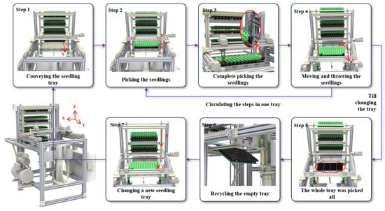
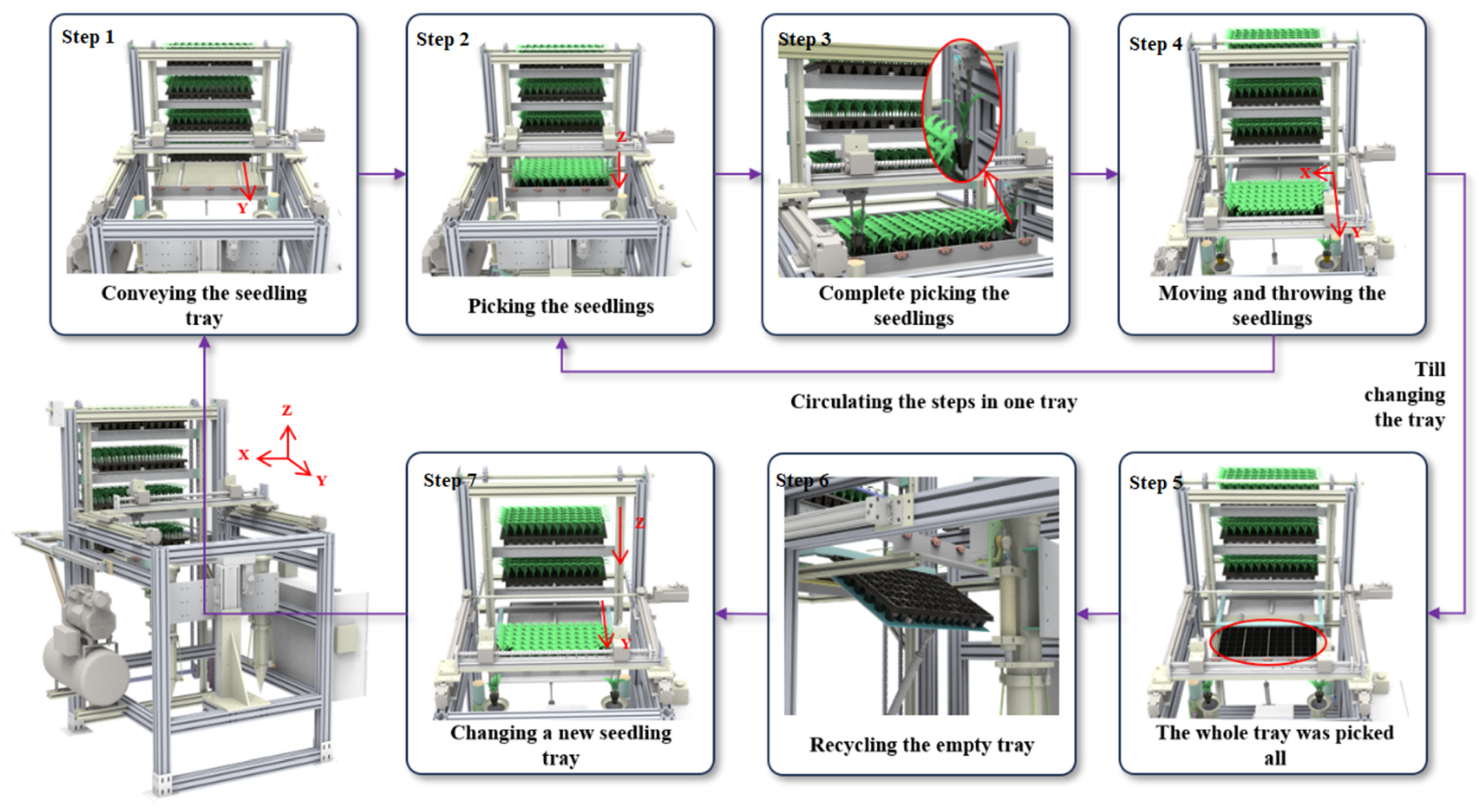
Before the operation, four trays with seedlings are placed into the multi-layer tray-handling mechanism manually. Then, the start button can be pressed, and the system can automatically convey, pick, throw and plant the seedlings and handle and recover the trays. The steps are shown in Figure 3.
Figure 3.
Operational sequence of the mechanism with seven steps.
Step 1: The position of the first seedling tray in the multi-layer tray-handling mechanism (from the bottom to the top is the first one to the fourth one) is aligned with the tray-conveying mechanism, so the conveying cylinder will open directly, and the seedling tray will be pushed to the picking position in the Y direction. The tray is held in a fixed physical position, which can avoid the displacement caused by vibration and inertia during the conveying and picking process.
Step 2: The initial position of the dual-claw seedling picking mechanism is directly above the first column and the first row once the tray is in place, so the picking operation will be carried out in the Z direction (the detailed actions have been clarified in Section 2.1.2).
Step 3: The dual-claw seedling picking mechanism will move in the X and Y directions cooperatively after clamping the seedlings.
Step 4: When the seedling picking mechanism moves above the planting tubes, the duck-bill planting mechanism will move in the Z direction to plant the seedlings.
The seedling picking device will pick and throw the remaining seedlings successively in the same tray and will cycle from step 2 to step 4.
Step 5: The whole tray will be picked after 36 cycles.
Step 6: When the tray is completed, the cylinder of the recovery device will close and the empty tray will automatically fall off, and then the cylinder will immediately open.
Step 7: Then, the cylinder of the tray-conveying mechanism is reset so that the multi-layer tray-handling mechanism will move downward in the Z direction to align the second seedling tray with the conveying device, and it will be pushed to the picking position.
The mechanism cycles through step 1 to step 7 until all four seedling trays are completed.
2.3. Research on the Trajectory and Motion Control of Dual-Claw Seedling Picking
Research on the dual-claw seedling picking and throwing mechanism is key to determine the optimal motion path of the strategy, so as to achieve the objectives of the shortest movement time, the minimum total displacement, the lowest energy consumption, and the least damage to the seedlings. At the same time, the stability of the process needs to be ensured to reduce the vibration caused by acceleration and deceleration changes, and avoid the problem of seedling pots falling in advance, which will affect the accuracy of seedling picking and throwing.
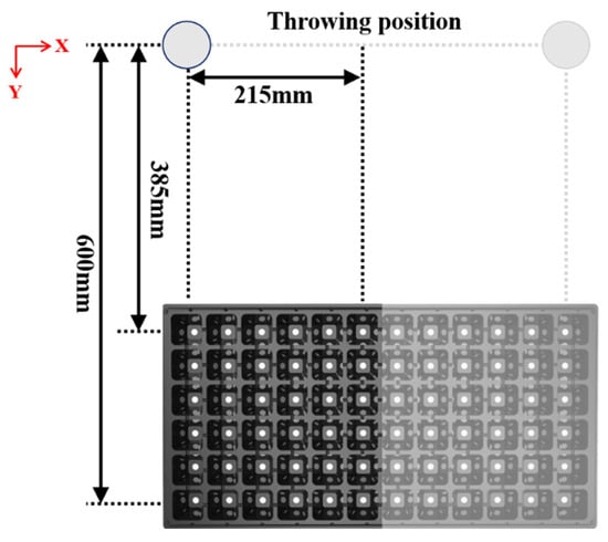
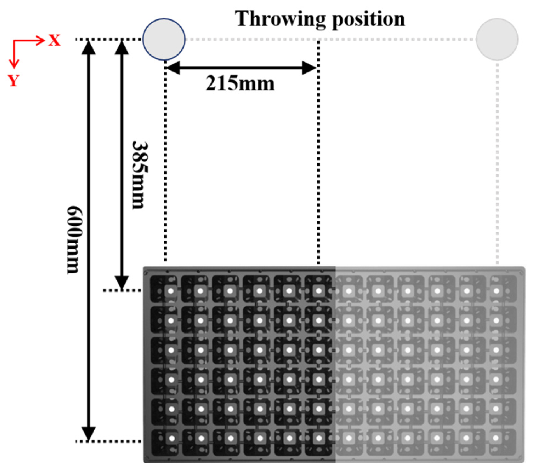
As illustrated in Figure 4, the position of the seedling tray, the seedling picking position and the seedling throwing position remain fixed throughout the operation. In the Y direction, along the long side defined as rows, the distance from the center point of the first row of the seedling tray to the center point of the throwing position is fixed at 385 mm. The distance increases progressively by 43 mm per row, reaching 600 mm at the sixth and final row. In the X direction, along the short side defined as columns, the center point of the first column of the seedling tray is aligned with the center point of the throwing position. The distance between the center point of the sixth column and the center point of the throwing position is fixed at 215 mm, with a uniform increment of 43 mm per column. The system employs two picking claws and two throwing positions per tray, which operate simultaneously in a symmetrical arrangement. Both claws follow identical trajectories in the Y direction, while moving in opposite directions along the X direction.
Figure 4.
The diagram of seedling picking and throwing position.
2.3.1. Multi-Layer Tray-Handling Mechanism
In the ideal condition, each seedling in the tray is correctly planted, so the tray only needs to be traversed in a fixed order. The traversal path refers to the method for passing all the points that need to be accessed with a given region. In the 72-hole tray, the picking claws will move from the picking points to the throwing points and have to pass through all holes in turn. The set of the hole locations is and the distance matrix between the points is , where indicates the distance from hole to hole . The goal is to minimize the total path length, which is shown in the formula:
where is the access sequence of the points and it should be the closed path.
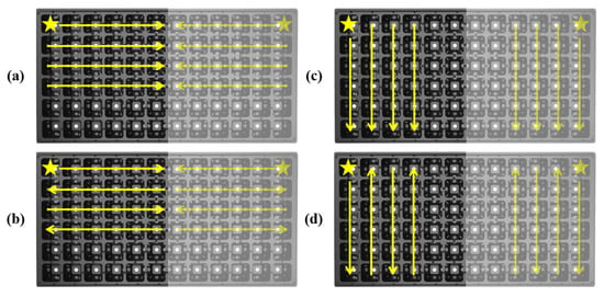
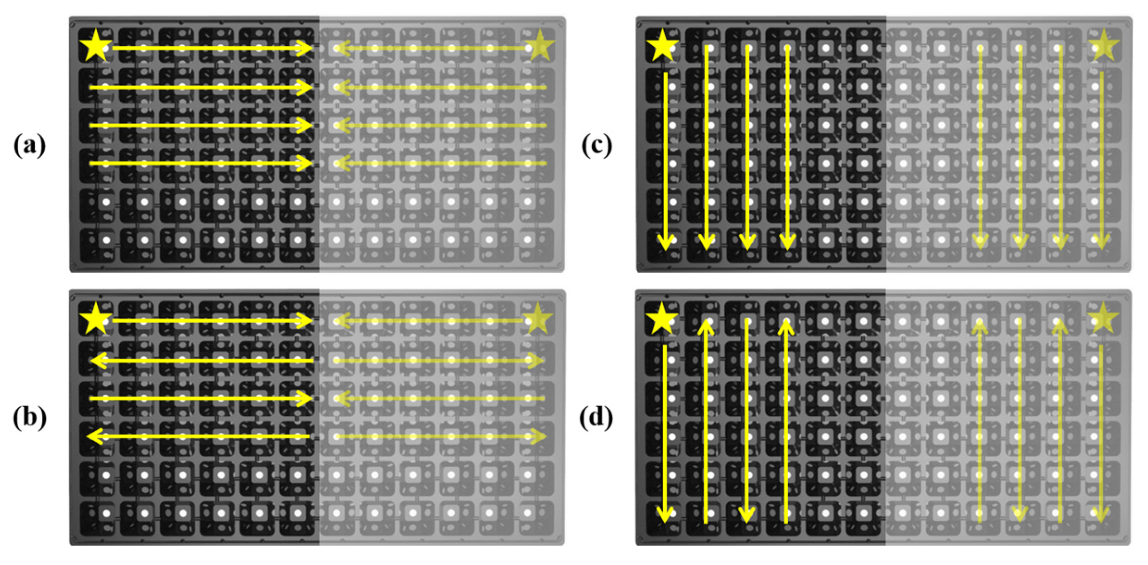
There are four paths in Figure 5: line-by-line scanning (a), line-wise S-round traversal (b), column-by-column scanning (c), and column-wise S-round traversal (d). In Formula (2), the total length of the four paths is the same. At the same time, in order to prevent picking of the remaining seedlings in the tray when picking seedlings, it is necessary to ensure that the path of picking and throwing cannot pass the remaining seedlings. So, the path of column-wise S-round traversal is excluded. From the perspective of energy consumption, the path with better inertia maintenance is preferred to reduce the kinetic energy loss caused by steering. When the curvature change rate of the path is evaluated, the trajectory with less acceleration fluctuation should be selected. Based on this, the path of line-wise S-round traversal is excluded because it needs to repeatedly maintain the state of high acceleration at the sixth and seventh picking positions. Furthermore, the horizontal distance is much less than the longitudinal one, which means that at the same time the horizontal speed is greater than the longitudinal speed, so for a single row or column the total time of progressive scanning of a row is less than for a column. Finally, the path of line-by-line scanning is used in this research.
Figure 5.
Different paths of seedling picking: (a) line-by-line scanning path; (b) line-wise S-round traversal path; (c) column-by-column scanning path; (d) column-wise S-round traversal path.
2.3.2. The Establishment of the Motion Mode for the Two Modules
Based on the decomposition of the motion process, the motion mode can be summarized into two main modes: dual-module serial motion mode and dual-module parallel motion. A serial motion mode means that the vertical synchronous belt linear module first drives the horizontal positive and negative ball screw module to move to the longitudinal target position of the hole in the tray, and then the horizontal positive and negative ball screw module further drives the end-effector to precisely determine the transverse target position in the hole. However, the parallel motion mode means that the vertical synchronous belt linear module and the horizontal positive and negative ball screw module move together to reach the seedling point directly through the synchronous drive of the end-effector, and continue to transport the seedlings to the throwing point through the parallel drive of the dual modules.
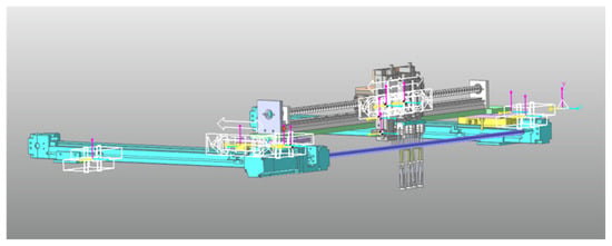
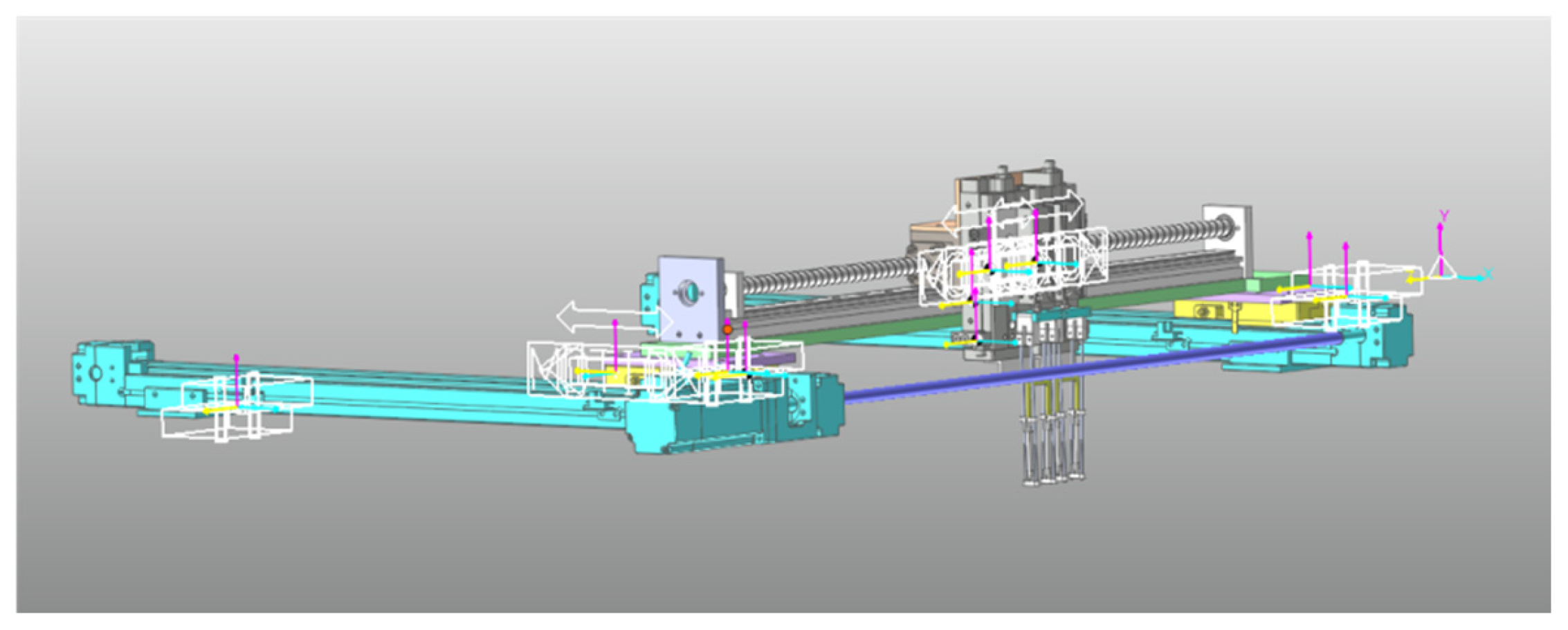
In the serial motion mode, although the picking mechanism can effectively suppress resonance and improve motion stability, its operational cycle is prolonged, resulting in relatively low efficiency. If the movement speed of a single module is increased to reduce cycle time, the vibration amplitude of the module will rise significantly, while inertial effects intensify, thereby compromising positioning accuracy during seedling picking. In contrast, the parallel motion mode substantially shortens the operational cycle and enhances efficiency. However, due to the superimposed vibration amplitudes of the two modules, the overall vibration may escalate, adversely affecting operational stability and precision. So, to assess the performance differences between the two motion modes, a systematic comparison of their trajectories is essential. The multibody dynamics simulation software RecurDyn (V2023) is employed to simulate and analyze both motion strategies under identical displacement and velocity conditions. The analysis focuses on two optimization objectives: a minimized cycle time and the trajectory geometry. The results will determine the optimal motion mode, providing a theoretical foundation for designing and refining the motion strategy of the picking mechanism. Figure 6 shows the kinematic simulation model of the dual-claw seedling picking mechanism.
Figure 6.
The kinematic simulation model of the dual-claw seedling picking mechanism.
As indicated in Table 1 and Figure 5, the maximum allowable velocities for the vertical synchronous belt linear module and the horizontal bidirectional ball screw module are , set at 500 mm/s, and , set at 1000 mm/s, respectively. To streamline the motion simulation, both modules are assumed to follow trapezoidal velocity profiles with equal acceleration and deceleration phases.
Two distinct operational modes, serial and parallel, are applied to the horizontal module, while the vertical module operates identically in both cases. The corresponding kinematic parameters for each module under the respective modes are detailed in Table 4.
Table 4.
Kinematic parameters of the motion profiles implemented for each module.
The vertical module travels a fixed distance of 600 mm, reaching its maximum velocity of 1000 mm/s after an acceleration phase of 0.2 s, which is maintained for another 0.2 s, resulting in a total motion time of 0.6 s. In the serial mode, the horizontal module covers 215 mm, accelerating to 500 mm/s in 0.2 s and continuing at a constant velocity for 0.8 s, completing its trajectory in 1.2 s. Under parallel operation, the horizontal module follows the same acceleration profile but remains at a constant speed slightly longer, for 0.83 s, leading to a total duration of 1.23 s. These parameters collectively define the coordinated motion profile of the dual-claw system, ensuring synchronized and efficient seedling transfer under dynamically variable spacing conditions.
2.3.3. The Planning of the S-Curve Motion Curve
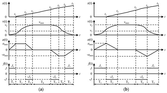
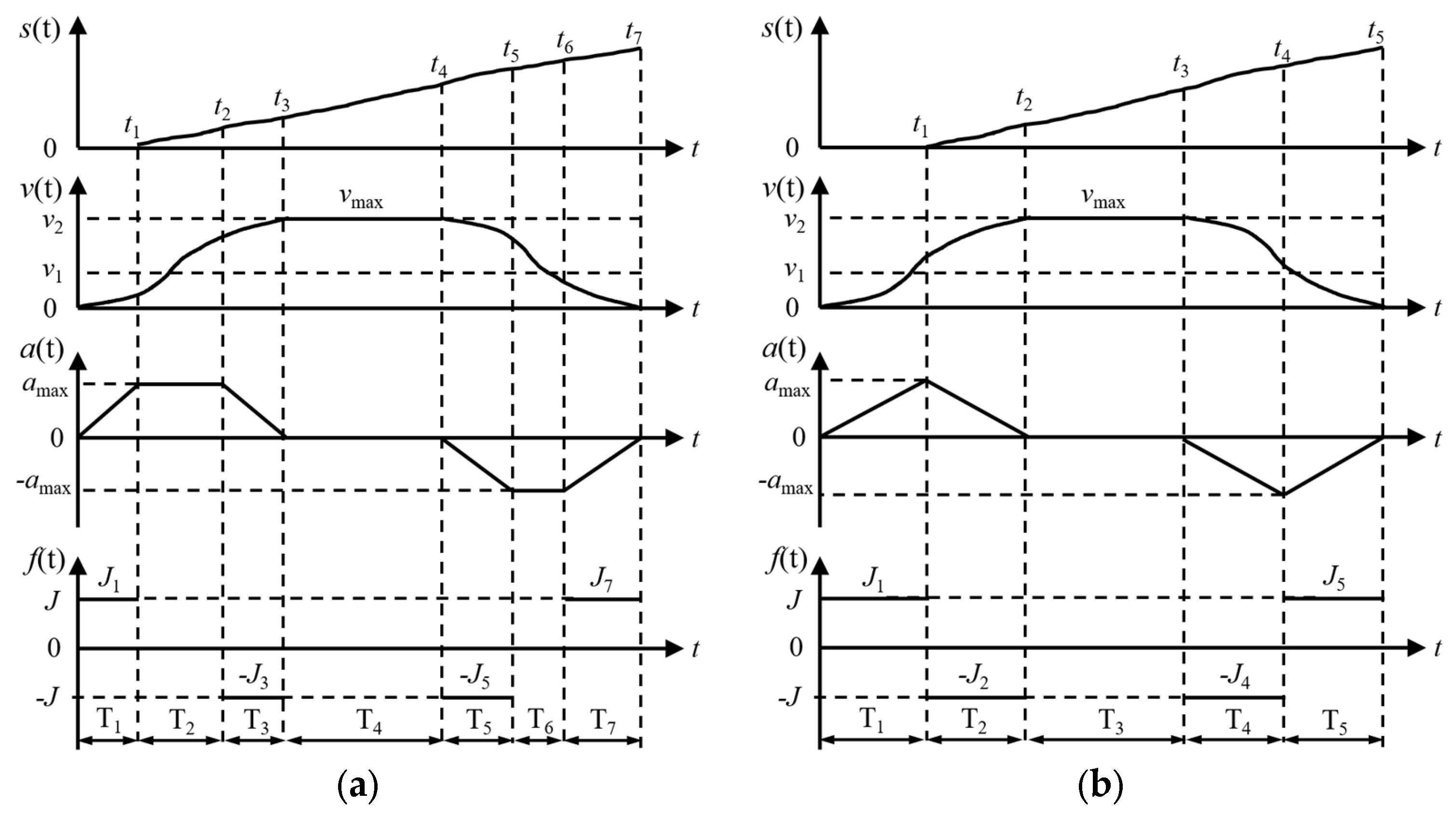
No matter what kind of motion mode is established, the acceleration–deceleration motion still needs to be regulated to shorten the working time and improve the stability. Common acceleration–deceleration motion profiles include uniform, variable, S-curve, trapezoidal, polynomial, exponential and custom acceleration–deceleration [29]. Among them, to avoid the impact and vibration caused by speed mutation and reduce mechanical wear, the S-curve acceleration–deceleration motion is applied in precision equipment. By ensuring smooth changes in acceleration and speed, shock and vibration can be reduced. According to different methods of acceleration change, the S-curve acceleration–deceleration motion can be divided into seven stages, five stages and three stages in the standard classifications.
Seven-stage S-curve motion is shown in Figure 7a, and five-stage S-curve motion is shown in Figure 7b, which is a simplification of the seven-stage curve. The motion curve of the seven-stage form is smoother than that of the five-stage form, so seven-stage S-curve motion is more often used. The process of seven-stage S-curve motion is divided into seven stages: the increasing acceleration stage, the constant-acceleration stage, the decreasing acceleration stage, the constant-velocity stage, the increasing deceleration stage, the constant-deceleration stage, and the decreasing deceleration stage.
Figure 7.
S-curve acceleration–deceleration motion: (a) seven-stage motion; (b) five-stage motion.
By specifying the displacement, maximum allowable speed, and maximum allowable acceleration and acceleration, the motor’s performance capabilities are fully utilized to complete the movement at the fastest speed while reducing the impact and vibration of the system.
In S-curve motion, the speed cannot exceed the maximum allowable speed of the system, which is determined by the motor, mechanical structure and control system. In the model, whether a uniform-velocity stage is required depends on the actual displacement. If the displacement is small, the system may not be able to reach its maximum speed, so the constant-velocity stage is not required. Therefore, the critical displacement needs to be calculated, and when the total displacement is less than the critical displacement, the system cannot reach the maximum velocity.
To determine whether the constant-velocity stage is needed, the displacement of acceleration stage and the deceleration stage should be calculated.
The acceleration and the deceleration are symmetric, so the total displacement is twice the displacement of acceleration stage.
where , and correspond to the displacement of the jerk-up stage, constant-acceleration stage and jerk-down stage, respectively.
The corresponding displacement of the three stages are as follows:
The formula of the velocity is as follows:
Substitute Formula (6) into the above formulas:
where is the critical velocity under the critical displacement, in mm/s.
Therefore, the critical displacement is calculated as follows:
where is the maximum acceleration allowed by the system, in mm/s2. is the maximum jerk allowed by the system, which is the rate of change of the acceleration, in mm/s3.
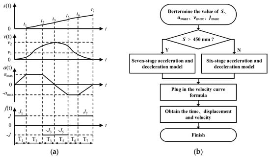
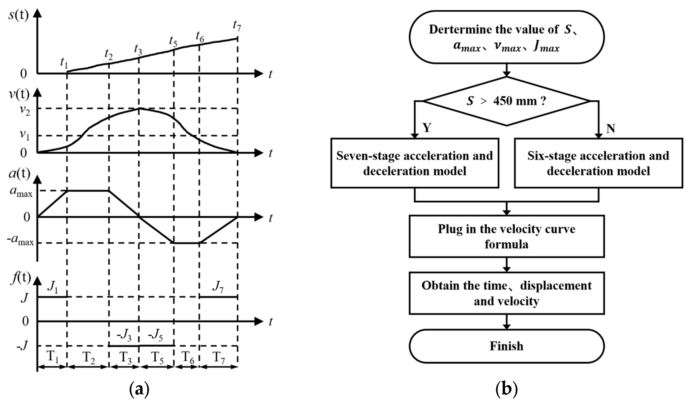
According to Table 3, taking the vertical movement for example, the maximum velocity is 1000 mm/s, the maximum acceleration is 4000 mm/s2, and the maximum jerk is 20,000 mm/s3. In Formula (8), the critical displacement is 450 mm, which means when the total displacement is less than 450 mm, the system does not need the constant-velocity stage, so the motion can be simplified to the six-stage motion shown in Figure 8a. Therefore, the S-curve motion curve should be planned and this is shown in Figure 8b.
Figure 8.
(a) Six-stage motion; (b) the planning of the motion of this system.
In Figure 4, the distance from the first row to the throwing position is 385 mm, so the six-stage motion should be used here. The distance from the second row to the throwing position is 428 mm, so the system still chooses the six-stage motion. From the third row to the sixth row, the distance is greater than 471 mm, so the seven-stage motion is used.
In order to verify whether the final velocity, displacement and time curves are smooth in the fixed parameters, the simulation software MATLAB (R2023a, version 9.14) was used for the seedling picking mechanism to verify that the planned S-curve acceleration and deceleration motion is feasible.
The displacement between the second row and the throwing position (S = 428 mm) was selected as the simulation target of the six-stage S-curve motion, and the displacement between the sixth row and the throwing position (S = 600 mm) was selected as the simulation target of the seven-stage S-curve motion. These two distances were the farthest displacements under the corresponding S-curve movement. They can better reflect the motion characteristics under each curve type.
2.4. Design of the Control System
2.4.1. Hardware System
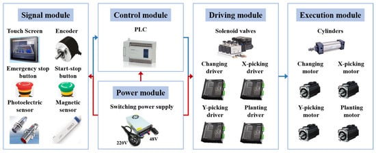
The hardware diagram of the control system of the whole mechanism is shown in Figure 9, which is mainly divided into a signal input module, a control processing module, a driving and execution module, and a power module. In the signal module, there are five photoelectric sensors for positioning, six magnetic sensors for detecting position, one start and stop switch, one reset switch, one emergency stop switch, and also one interface touch screen and one encoder which are used for the input of planting signals. The main control module is a programmable logic controller (PLC, model XD10-48T6-C, Xinje, Wuxi, China), which is selected according to the number of input and output ports. The driving module contains the motor driver and cylinder solenoid valve, and the execution module consists of the servo motor and the cylinder responsible for handling the tray and picking and planting the seedlings. The power module is connected to a 220 V household power supply, and converts the alternating current into direct current through the switching power supply to provide power for other components of the mechanism.
Figure 9.
The hardware diagram of the control system.
The versions of the sensors, touch screen, encoder, motor, cylinder and other related electronic components selected are shown in Table 5. Among them, the controller is the most vital, used for calculation and the distribution of inputs and outputs. Meeting the input and output requirements is a key criterion for PLC selection, Table 6 specifies that the chosen unit must possess 14 inputs and 14 outputs.
Table 5.
The version of the components.
Table 6.
Input and output of the PLC.
2.4.2. Software System
A PLC is a kind of system for controlling the input and output of the automation process that uses a ladder diagram; it can complete a variety of functions through the combination of different modules. The version of the control system software is 3.7.4a.
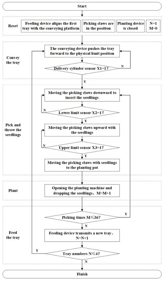
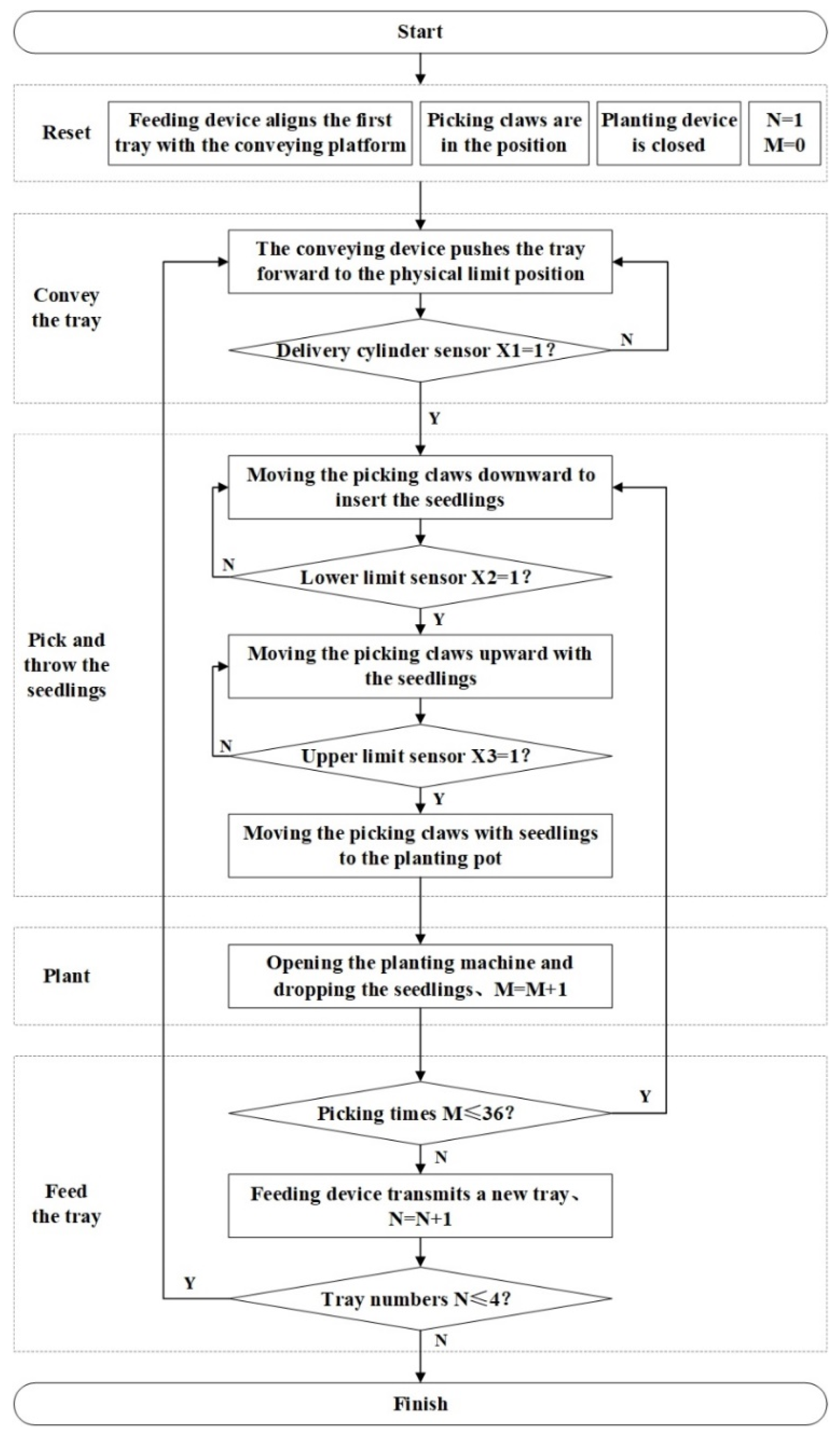
Figure 10 shows the software flowchart of the control system, which illustrates the cycle of cooperation for the handling, conveying, picking and planting of a 72-hole tray. The entire system is primarily divided into five operational phases: the reset phase, the seedling tray-conveying phase, the seedling picking and throwing phase, the planting phase, and the tray-handling phase. During the reset phase, it is ensured that the multi-layer handling mechanism, dual-claw seedling picking mechanism, and duck-bill planting mechanism are positioned at their initial states. Specially, the first seedling tray in the multi-layer handling mechanism is aligned with the tray-conveying device, so that the system can immediately transport the tray and trigger the sensor X1 to confirm the tray positioning during the seedling conveying phase. The picking claws rest directly above the first cavities on both sides of the tray, so during the seedling picking and throwing phase, the dual-claw mechanism initiates a descending–insertion–clamping motion to pick the seedlings, and sequentially activates the corresponding sensors (X2 and X3). After picking, the claws will move above the planting tubes to release the seedlings, awaiting the planting signal. Once the two seedlings are released into the planting guiding tubes, the duck-bill planting mechanism will execute the planting operation; at the same time, the dual-claw seedling picking mechanism will move to above the seedling tray to pick another two seedlings for the next cycle; the picking times (M) increment with each picking action. After 36 cycles, the system initiates tray handling, enabling the continuous cycling of four trays.
Figure 10.
The software diagram of the control system.
2.5. Experiments
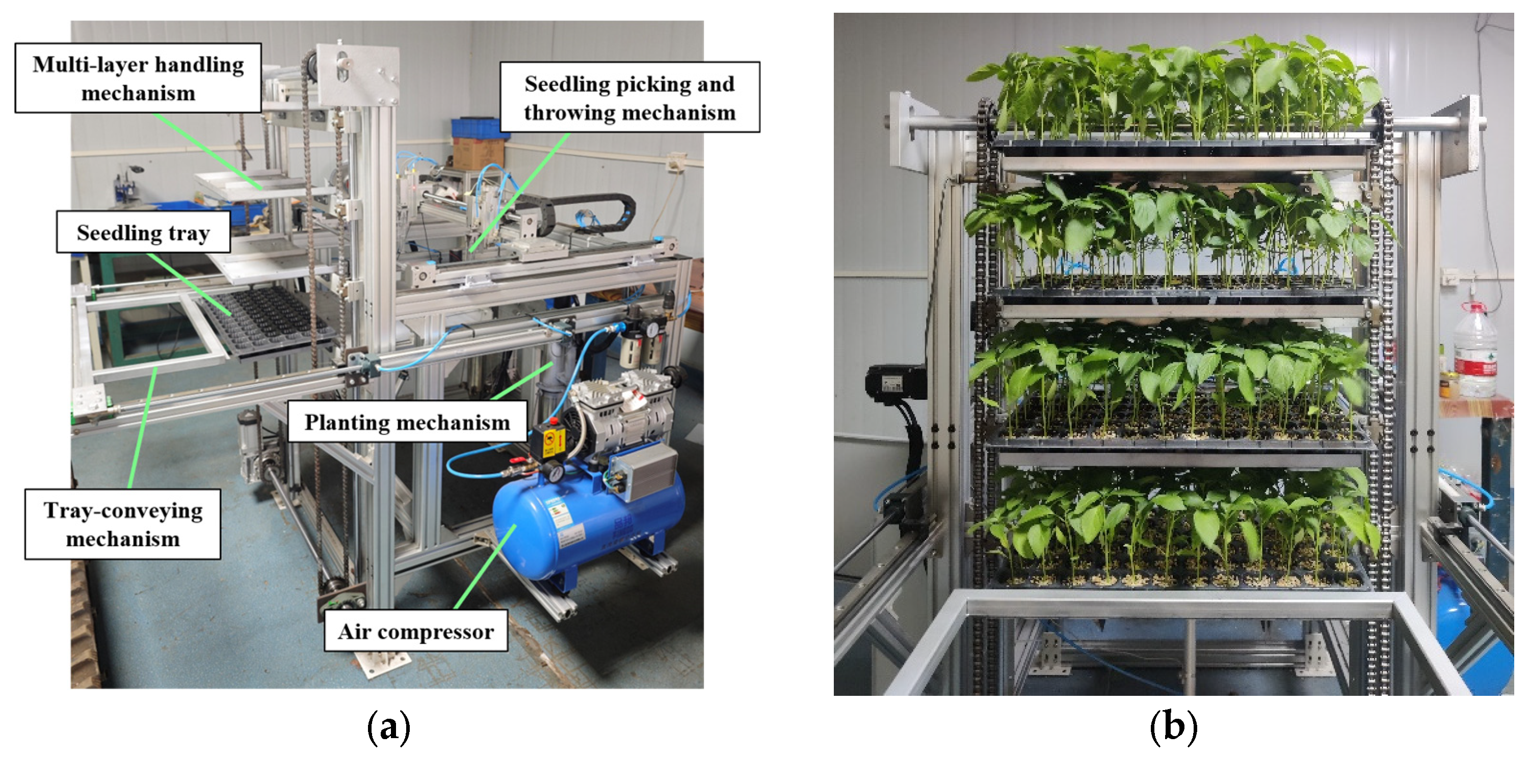
To evaluate the accuracy of seedling conveying and picking, as well as the fluency of the dual-claw picking movement, a dedicated test was implemented. The experimental setup, as illustrated in Figure 11, incorporated tools including vernier calipers, markers, stopwatches, three-axis accelerometers, laptops, and a camera. The seedling tray used in the experiment was had a standard 72 holes (280 × 540 × 43 mm); pepper seedlings (Jing Line No. 1) cultivated to form standardized root balls were used as the test objects. This variety has been widely cultivated in the market, with established cultivation protocols, and it has been widely adopted in prior seedling picking studies, as the resulting seedling bodies exhibit consistent root system strength and tray compactness, meeting the physical property requirements of automated seedling picking operations for baseline materials. The seedling age was 40~50 days and the pepper seedlings had grown to two leaves or three leaves in one core, and the seedling height was 150~180 mm. The test site is located in Jiangsu university, Zhenjiang, China.
Figure 11.
Test equipment and supplies: (a) Test bench; (b) multi-layer tray-handling device with seedling trays.
2.5.1. Verification of Motion Control for Seedling Picking
The S-curve acceleration and deceleration motion control algorithm was applied to the system to control the longitudinal and transverse motor motion of the seedling picking mechanism. Three-axis accelerometers and a data acquisition instrument were used to measure and record the actual motion acceleration of the device, and the data was transferred and output to the computer. The data was processed by the software MATLAB and the velocity and acceleration curves can be used to verify the reliability of the motion. The verification indexes of S-curve motion are the velocity curve (v-t) and the acceleration curve (a-t) of the picking claws and the motion time T under different acceleration and deceleration calculation methods. The test variables are, respectively, the six-stage and seven-stage S-curve acceleration and deceleration motion models.
2.5.2. Positioning Accuracy of Seedling Handling and Conveying
The continuity and precision of seedling handling and conveying were evaluated experimentally. In the vertical direction, markers were used to indicate the point at which each tray reached its designated position, and the actual location was recorded. The theoretical position corresponds to the preset alignment of the seedling conveying device. Horizontally, the tray was advanced to the picking position, defined as the theoretical location, and the actual position was measured using a Vernier caliper. The error analysis of the actual position and the theoretical position in two directions was carried out respectively. In order to increase the reliability of the test data, a test with eight consecutive trays was carried out on the machine.
The test index is the relative absolute error between the actual position and the theoretical position. According to the industry standard for dryland planting machinery [30], an absolute error within 2 mm is allowed for seedling position. represents the theoretical displacement of each tray in the tray-conveying direction, represents the theoretical displacement in the vertical direction for tray handling. is the actual displacement in the horizontal direction and is the actual displacement in the vertical direction. is the absolute positioning errors in the horizontal direction and is that of the vertical direction, the formulas are as follows:
2.5.3. Positioning Accuracy and the Success Rate of Seedling Picking and Throwing
The test for the positioning accuracy of seedling picking and throwing was carried out with a frequency of 30 seedlings per row per minute. The lateral and longitudinal position absolute errors of the hole to the picking claws were measured, respectively, and a single claw was taken as an example. In the system, the point moving program was used to measure the absolute error. Four seedling trays were utilized and 36 seedlings were systematically selected from each to measure the absolute errors; a total of 144 groups of data were tested.
The test index is the relative absolute error between the actual position and the theoretical position, and, respectively, the absolute error in two directions during seedling picking and throwing. The position absolute error P can be obtained by measuring from the picking claw to the seedling hole and in the horizontal and in vertical directions, the absolute errors are and . The position absolute error T can be obtained by measuring from the picking claw to the guiding tubes and in the horizontal and in vertical directions, the absolute errors are and . The coefficient of variation was used to verify the data stability and was calculated using the following formula:
where is the coefficient of variation of the absolute error, %. is the standard absolute error of absolute error, and is the average absolute error in mm.
According to the industry standard for dryland planting machinery [30] and the dimensions of the tray’s holes and the guiding tubes, the allowable displacement absolute error for positioning when picking the seedlings is ±2 mm in the horizontal and vertical directions; the allowable displacement absolute error for positioning when throwing the seedlings is ±3 mm in the horizontal and vertical directions. Also, in the actual picking operation, absolute errors less than 2 mm were found to not affect the claw’s ability to successfully pick from the hole, and thus were considered qualified. The successful picking rate () was calculated as the percentage of successfully picked seedlings using the picking claws:
where is the rate of successful picking of seedlings and %. is the number of seedlings successfully picked from the tray in pcs. is the numbers of seedlings per tray in pcs.
2.5.4. The Success Rate of Seedling Planting
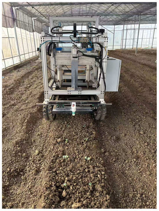
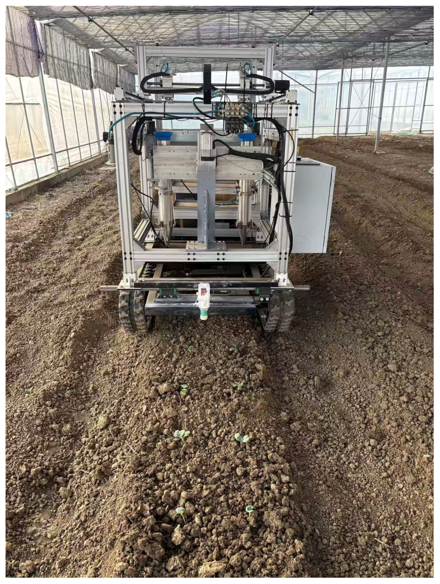
The field trial was conducted at the Zhen jiang agricultural science and technology incubation base in Jiangsu Province, China (119.302928° E, 32.222543° N), which is shown in Figure 12. By measuring the values of multiple plant spacings, the stability of the planting frequency can be obtained to examine whether the designed planting component and the electric planting motion control meet the requirement for effective planting frequency. Five groups with four trays per group were used in the test and they were randomly measured, with 50 in each group. The values of plant spacing were recorded, and the mean, standard absolute error and coefficient of variation of the plant spacing were calculated.
Figure 12.
The field trial of the automatic transplanter.
The planting frequency rate () was calculated as the effectiveness of planting; the formula is as follows:
where is the effectiveness of planting frequency, in %. is the number of planting spacings within the standard range; is the total number of measured planting spacings.
The mean (), standard absolute error (), and coefficient of variation () of planting is as follows:
where represents the value of the plant spacing in mm.
3. Results
3.1. Results of Research on Dual-Claw Seedling Picking
3.1.1. Trajectory Comparison
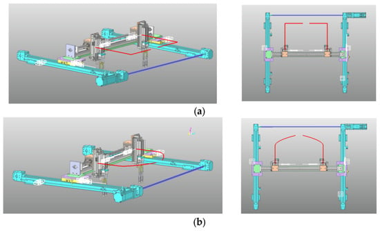
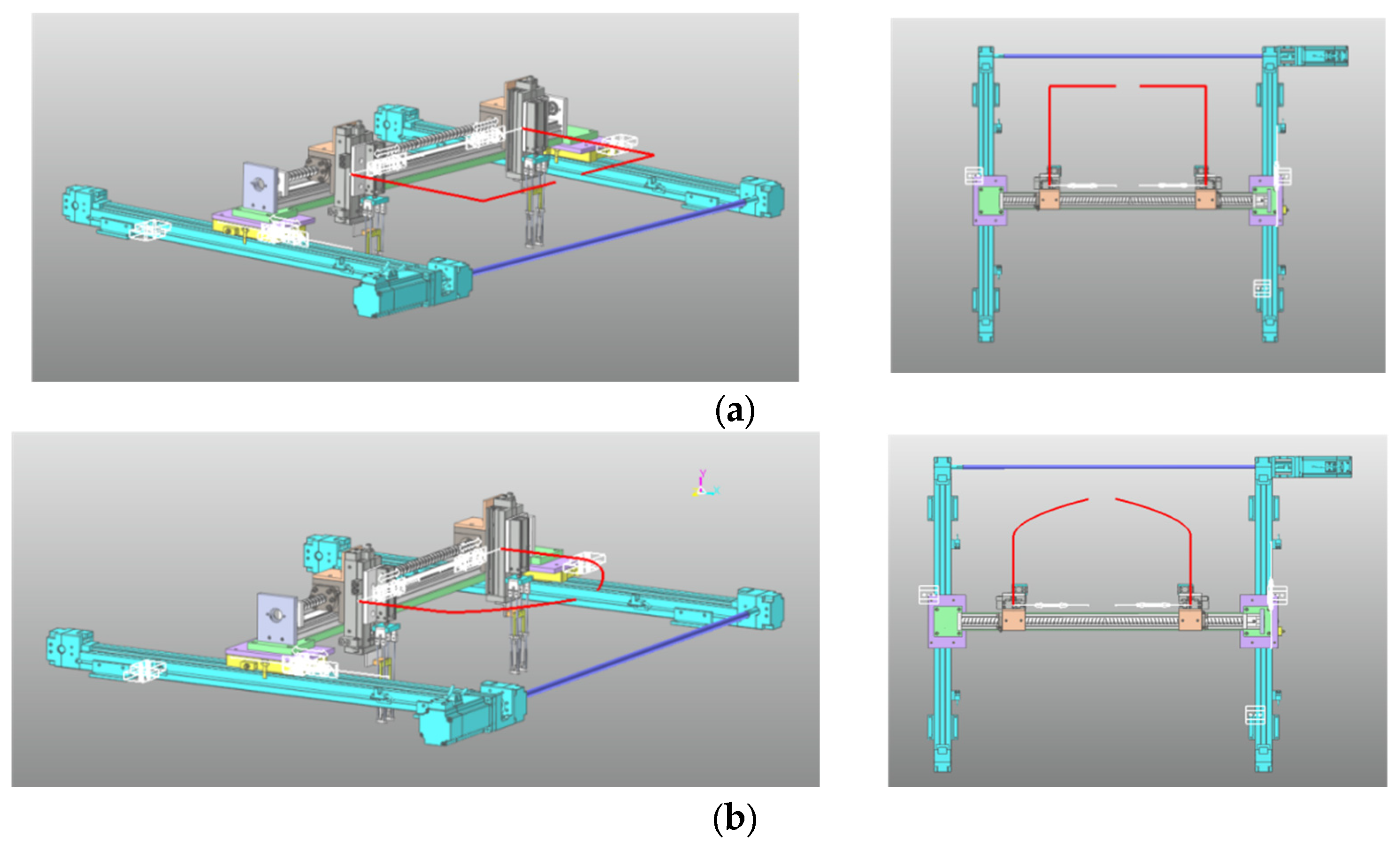
The trajectory tracking points of the two end-effectors were added to simulate the motion trajectory. The simulation process and the motion trajectory after completion are shown in Figure 13.
Figure 13.
The trajectory comparison of two different motion modes: (a) the dual-module serial motion mode; (b) the dual-module parallel motion mode.
In the dual-module serial motion mode, the dual-claw seedling picking mechanism follows an L-shaped trajectory comprising two orthogonal linear segments. Motion along each axis proceeds independently, thereby eliminating the potential interference inherent in simultaneous actuation. However, this sequential operation results in suboptimal efficiency, as the total cycle time equals the sum of the durations required for each directional movement. Moreover, the abrupt directional changes during motion induces mechanical oscillations, causing tray tilting or even seedling detachment, which adversely affects transfer reliability and placement accuracy. Each axis must undergo at least two acceleration–deceleration cycles per start–stop sequence, introducing disturbances that compromise system stability, exacerbate mechanical vibrations, and impose additional stress on the drive motors.
In the dual-module parallel motion mode, the device exhibits a smooth arc-shaped trajectory with a continuous curvature. The concurrent actuation of both axes significantly reduces the total cycle time. Compared with the serial motion mode, the parallel motion mode enhances the motion smoothness with only one start and stop cycle, minimizing vibration frequency, and eliminates the intermittent inertial loads, improving the dynamic stability and energy efficiency.
3.1.2. Simulation of S-Curve Motion
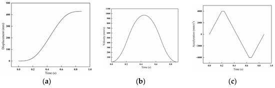
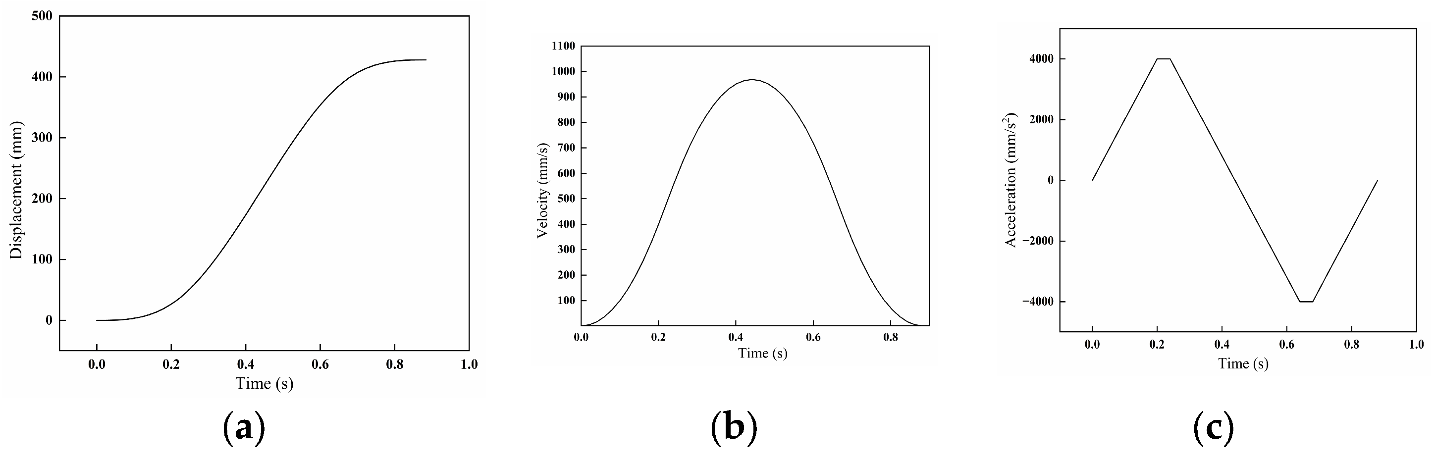
When the is 428 mm, the curves of the displacement, velocity and acceleration of the end-effector under the six-stage S-curve acceleration and deceleration motion are shown in Figure 14. The displacement curve shows the total displacement gradually increasing from 0 to 428 mm with a smooth trend and no abrupt changes, consistent with the characteristics of an S-curve acceleration and deceleration model. The handling slope of the displacement curve reflects smooth velocity transitions. In the velocity curve, the speed first increases and then decreases, displaying a distinct peak that indicates acceleration to the maximum speed, followed by deceleration without a constant-velocity stage, which matches the six-stage motion. The acceleration curve rises to a maximum value, decreases to negative values, and finally returns to zero, forming a symmetrical waveform. The smooth variations demonstrate continuous acceleration changes during motion.
Figure 14.
The curves of six-stage S-curve acceleration and deceleration motion: (a) displacement curve; (b) velocity curve; (c) acceleration curve.
During the motor process, the phase durations are = 0.2 s, = 0.042 s, and the total time is 0.884 s. The average speed of this motion is about 484 mm/s, and the maximum speed is about twice the average speed because the time distribution of the acceleration and deceleration is symmetrical, 968 mm/s, which is close to the maximum speed of 1000 mm/s. According to the maximum speed and the acceleration time = 0.2 s, the average acceleration can be obtained at 4840 mm/s2, and the maximum acceleration is about 8 times the average acceleration because the acceleration curve of the model is smooth, 38,720 mm/s2, which is close to the maximum acceleration of 40,000 mm/s2 originally set.
The smoothness of the acceleration and deceleration motion can reduce the impact and vibration of the mechanism in practical applications, improve the precision and stability of the motion control, and ensure that damage caused by mechanical shaking can be reduced in the process of picking and throwing seedlings.
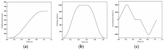
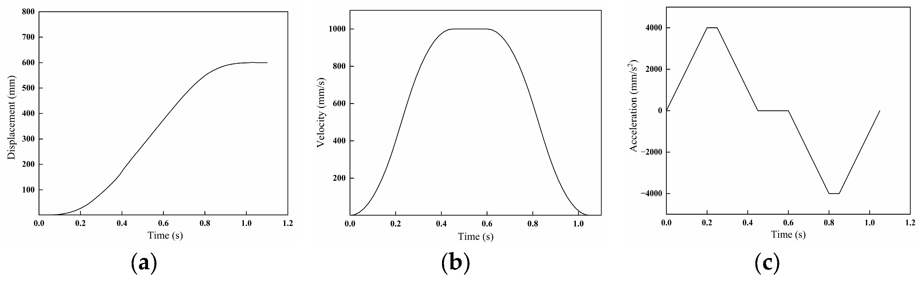
When the is 600 mm, the curves of the displacement, velocity and acceleration of the end-effector under the seven-stage S-curve acceleration and deceleration motion are shown in Figure 15. Specifically, the formula of is as follows:
where is the maximum speed of this system in mm/s.
Figure 15.
The curves of seven-stage S-curve acceleration and deceleration motion: (a) displacement curve; (b) velocity curve; (c) acceleration curve.
In the displacement curve, the total movement gradually rises from 0 to 600 mm, and the overall trend is smooth without abrupt changes or jumps. The slope of the displacement curve changes gradually, reflecting the smooth transition of the velocity. It can be seen that the whole process reflects continuous and unique changes, which fits the characteristics of seven-stage S-curve acceleration and deceleration motion. In the velocity curve, the constant-velocity stage is experienced, which is obviously different from the six-stage curve, while the whole process still maintains smooth changes. In the acceleration curve, the acceleration first increases to the maximum value, then decreases to 0, then decreases to a negative value, and finally returns to 0, presenting a symmetrical waveform, and the smooth change indicates that the acceleration changes continuously during the movement.
During the motor process, the phase durations are = 0.2 s, = 0.05 s, = 0.15 s, and the total time is 1.05 s. The average speed of this motion is about 571 mm/s, and the maximum speed is about twice the average speed, 1142 mm/s, close to the maximum speed of 1000 mm/s. According to the maximum speed and the acceleration time = 0.2 s, the average acceleration can be obtained at 5710 mm/s2, and the maximum acceleration is about 8 times the average acceleration, 45,680 mm/s2, because the acceleration curve of the model is smooth, and this is also close to the maximum acceleration of 40,000 mm/s2 originally set.
The consistency of the S-curve acceleration and deceleration motion planned according to the target parameters is verified with the general mathematical theory formula and motion parameters with the simulation of the two types, and it is proved that the S-curve motion after planning can still maintain the original motion characteristics.
3.1.3. Motion Control Test
The acceleration of the end-effector is measured by the triaxial accelerometer, and the acceleration at different times is collected by the data acquisition instrument DH5920N (Donghua Test, Jinjiang, China), and the data is processed by MATLAB to obtain the speed and acceleration curve under the control of the S-curve acceleration and deceleration motion.
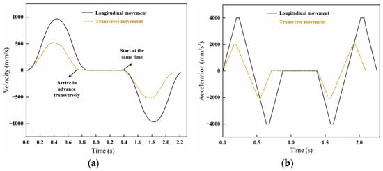
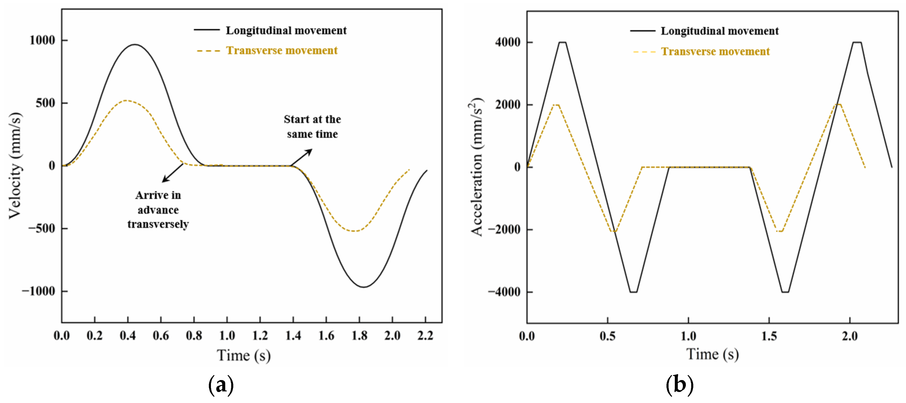
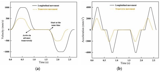
A complete process of seedling picking and throwing was taken as the period, which is twice the period in the simulation test in Section 3.1.2. The movement distance, time and speed change are consistent, or symmetrical. The six-stage and seven-stage S-curve acceleration and deceleration motion control models are consistent with the theoretical simulation parameters, and the stopping time of the middle motion is the seedling picking time of the end-effector.
The test results show that the longitudinal and transverse movements of the end-effector in the process of picking the seedlings are in accordance with the planned S-curve acceleration and deceleration motion, the speed changes gently, and the acceleration changes continuously, which is basically consistent with the curve obtained by the simulation test. It can be seen in Figure 16 and Figure 17 that the movement times in the transverse direction under the six-stage and seven-stage S-curve acceleration and deceleration motions are smaller than those in the longitudinal direction, which will make the machine reach the picking point faster in the horizontal direction, although they still start at the same time after the execution of the seeding throwing action. In one cycle, the total movement time under the six-stage motion is 2.27 s, and that of seven-stage motion is 2.6 s, including the 0.5 s of seeding picking and throwing time in the middle process. Before introducing the formula into the control system, the original ladder acceleration and deceleration motion model in the controller PLC was used, and the time used in a shooting cycle with the same distance as the seven-stage S-curve acceleration and deceleration model was measured to be 2.86 s. Comparative analysis shows that the movement time under S-type acceleration and deceleration control is shorter.
Figure 16.
The motion control curve of six-stage S-curve acceleration and deceleration motion: (a) velocity–time curve; (b) acceleration–time curve.
Figure 17.
The motion control curve of six-stage S-curve acceleration and deceleration motion: (a) velocity–time curve; (b) acceleration–time curve.
3.2. Results for Positioning Accuracy of Tray Handling and Conveying
The seedling tray-handling and conveying tests were carried out with eight consecutive trays. The actual displacements of the trays in both the Y direction (conveying) and Z direction (handling) were recorded and compared with the theoretical displacements. The direction is the same in Figure 3. The absolute errors were calculated to analyze the positioning accuracy of the seedling trays; the data is shown in Table 7.
Table 7.
Seedling handling and conveying positioning accuracy results.
The comparative analysis shows that during the consecutive tray-handling and conveying operations, the maximum absolute error of seedling tray handling is 2.3 mm, and the minimum is 0.6 mm; the average absolute error is 1.5125 mm. The maximum absolute error of multi-layer tray conveying in the vertical direction is 1.9 mm, and the minimum is 0.5 mm; the average absolute error is 1.0875 mm.
In the conveying direction, the tray is pushed by cylinder propulsion and stops with the cylinder’s physical stopper. With both lateral and front limiters in place during movement, the horizontal displacement errors remain consistently small, with the maximum errors well within the positioning accuracy requirements. In the handling direction, trays are moved by the chain drive device, with movement and stopping controlled by positioning sensors and motors. As long as the horizontal pusher can properly convey the trays, the allowable vertical displacement error is relatively larger and can be more than 2 mm, though the actual absolute error still meets the vertical tolerance requirements. During testing, automatic seedling conveying and multi-layer tray-handling was performed successfully and without any incidents of excessive positioning errors or tray jamming during conveying and handling.
3.3. Results of Positioning Accuracy and Success Rate of Seedling Picking and Throwing
The actual displacements of the seedlings both in the transverse and longitudinal directions for picking and throwing were recorded and compared with the theoretical displacements. The absolute errors and coefficient of variation were calculated to analyze the positioning accuracy of seedling picking and throwing; the data is shown in Table 8 and Table 9.
Table 8.
Seedling picking positioning accuracy results.
Table 9.
Seedling throwing positioning accuracy results.
Four trays were tested and each tray contained 36 seedling holes. Therefore, the reported data represent the average results per tray. As is shown in Table 8, the maximum absolute error of seedling picking in the transverse direction is 1.91 mm, the minimum absolute error is 0.64 mm, and the maximum average absolute error is 1.31 mm; the maximum coefficient of variation is 19.27%. For the four trays, the average absolute error is 1.07 mm and the average coefficient of variation is 16.9%. In the longitudinal direction, the maximum absolute error of seedling picking is 2.00 mm, the minimum absolute error is 0.51 mm, and the maximum average absolute error is 1.26 mm; the maximum coefficient of variation is 21.98%. For the four trays, the average absolute error is 1.09 mm and the average coefficient of variation is 20.79%.
The picking absolute error is less than that of , which may be related to the accumulated error of the initial seedling conveying in the longitudinal direction; the absolute error in seedling tray conveying may affect that of the seedling picking. So, the coefficient of variation in the longitudinal direction is greater than that of the transverse direction. The values of the two directions were both less than 2 mm, within the requirement of the industry standard for dryland planting machinery [30], and there were no instances of trays tangling during seedling picking.
As shown in Table 9, the maximum absolute error of seedling throwing in the transverse direction is 1.87 mm, the minimum absolute error is 1.73 mm, and the maximum average absolute error is 1.18 mm; the maximum coefficient of variation is 18.71%. For the four trays, the average absolute error is 1.50 mm and the average coefficient of variation is 17.98%. In the longitudinal direction, the maximum absolute error of seedling throwing is 1.90 mm, the minimum absolute error is 1.16 mm, and the maximum average absolute error is 1.58 mm; the maximum coefficient of variation is 19.04%. For the four trays, the average absolute error is 1.51 mm and the average coefficient of variation is 18.03%.
The throwing absolute errors and have little difference even though the absolute error allowance is 3 mm, and the data is more stable than that of the picking absolute error, which may be related to the fixed throwing position and the size of the planting guiding tubes. The picking claws move above the guiding tubes and the positioning accuracy satisfies the requirements of the operation.
Five tests were carried out on four seedling trays in each group and there were 288 seedlings picked totally; the data was used to verify the success rate of picking and throwing the seedlings. As is shown in Table 10, the maximum number of seedlings picked was 284, which means there were four seedlings that failed to be picked, and in this group, two more seedlings failed to be thrown into the guiding tubes. The maximum rate of successful picking was 98.61% and that of sucessful throwing was 97.92%. The average rate of successful picking was 97.01% and that of sucessful throwing was 96.39%.
Table 10.
Rate of picking and throwing successfully.
When picking the seedlings, there are cases where the seedling pots are broken because of the weak root system of the seedlings so the picking claws fail to hold the seedlings, and there are also cases where the seedling leaves are entangled, resulting in the phenomenon of seedling vacancies in the remaining tray. Then, during throwing of the seedlings, seedling leaves can hang on the guide tube, causing the seedling to fail to fall into the planting guide tube, which results from the failure of sucessful throwing. Therefore, it is necessary to ensure the stability of the object before the test, and carry out screening of the root of the seedling pot and check the seedling leaves in advance, so as to further ensure the accuracy of the seedling throwing.
3.4. Results of Success Rate of Seedling Planting
The planting spacing was fixed at 350 mm and the automatic transplanting machine completed the continuous operation. According to the industry standards of dryland transplanting machines, when the measured planting row spacing is within 20 mm of the set value, it is determined to be a valid planting row spacing, and the coefficient of variation of the planting row spacing is required to be less than or equal to 20%.
According to Table 11, when randomly selecting five groups of data with 50 plantings in each group and calculating the data, the average planting spacing reached 349.74 mm, which was close to the set value of 350 mm. The standard absolute error of the average planting spacing was 8.87 mm, and the coefficient of variation of the average planting spacing was 3.5%. This indicates that the performance of the planting components is correct, and the average effectiveness of the planting spacing reached 96%, meeting the performance requirements of the automatic transplanting machine. The reason for the instability of the planting spacing may be the suspension of the ground wheels, resulting in incorrect counting by the encoder. Errors occur in determining whether the planting spacing reaches the set value, and the difference between the actual value and the measured value causes the planting spacing to change.
Table 11.
Rate of seedling planting.
4. Discussion
The experimental results presented in this study demonstrate the effectiveness of the proposed dual-claw seedling picking and throwing system integrated with a multi-layer tray-handling mechanism.
Regarding the motion control, the adoption of a seven-stage S-curve acceleration–deceleration model for longer displacement paths (e.g., 600 mm) and a six-stage model for shorter ones (e.g., 428 mm) proved effective in achieving smooth speed transitions and minimal mechanical shock. The velocity and acceleration curves obtained from both the simulation (Figure 13 and Figure 14) and the physical tests (Figure 15 and Figure 16) showed close alignment, indicating that the planned motion profiles were accurately implemented in the control system [13]. The parallel motion mode reduced the total cycle time by approximately 9% compared to the serial mode, while maintaining trajectory smoothness and reducing directional abruptness. This is consistent with prior studies emphasizing the importance of continuous curvature in robotic path planning to minimize vibration and improve end-effector stability [10,16,31]. However, slight discrepancies between the simulated and measured acceleration curves were observed, particularly during the deceleration phases. These may be attributed to mechanical compliance in the screw and belt drive systems, as well as control response delays in the PLC-motor loop. Future implementations could benefit from real-time adaptive control strategies, such as model predictive control (MPC), to compensate for dynamic uncertainties and further enhance motion precision.
Regarding tray-handling and conveying, the multi-layer tray-handling mechanism achieved an average positioning error of 1.09 mm horizontally and 1.51 mm vertically, which is within the allowable tolerance of ±2.5 mm. The slightly higher vertical error is likely due to chain elongation and backlash in the sprocket drive system, which could be mitigated in future designs by using pre-tensioned timing belts or linear servo actuators [32].
Regarding seedling picking and throwing, the average lateral and longitudinal absolute errors were 1.07 mm and 1.09 mm, respectively, both within the ±2 mm standard. The higher coefficient of variation in the longitudinal absolute error during the seedling picking stage primarily stems from the cumulative positioning errors of the tray-conveying mechanism. Specific contributing factors include dynamic tracking errors in the servo system, minor elastic slippage in the synchronous belt transmission, and detection delays in the photoelectric sensors under high-speed operation. In contrast, systematic offsets in both the lateral and longitudinal directions are associated with imperfect alignment during mechanical assembly and inherent clearances in linear guide rails [33]. By comparison, the notably higher consistency in seedling throwing accuracy is largely attributable to the fixed positioning of the planting tubes and the guiding effect of their funnel-shaped structures, which effectively correct random postural absolute errors of the seedling plugs during release. Future optimization may involve targeted improvements in overall system accuracy through hardware-based precision calibration and compensation, combined with software-driven closed-loop feedback control.
The average seedling picking success rate of 97.01% and throwing success rate of 96.39% are comparable to, or exceed, those reported in recent studies on automated transplanting systems [34]. The main conclusions of this study (regarding the operational performance of the end-effector) are applicable to other crop seedlings capable of forming root balls with similar physical properties, such as solanaceous fruits (e.g., tomatoes, eggplants) and brassicas (e.g., cabbage, broccoli). Failures were primarily due to weak root systems in some seedling plugs, leading to breakage during extraction, or entangled leaves causing missed picks or hanging during transfer, or occasional misalignment between the picking needles and the seedling cavity. These issues suggest that seedling quality standardization and pre-transplant conditioning (e.g., root pruning, leaf separation) could further improve system reliability. Additionally, integrating machine vision-based detection could enable real-time adjustment of picking positions and reduce vacancy rates.
Regarding seedling planting, the planting success rate of 98.8% and spacing consistency confirm that encoder-based motion control is effective for field operations. The minor variations in planting spacing were likely caused by wheel slippage on uneven terrain, suggesting that ground speed synchronization via RTK-GNSS or inertial measurement could enhance spacing uniformity in field conditions
This study focuses on the principle verification and performance optimization of a new integrated transplanting scheme. As an iterative design, the success rate of picking seedlings has been improved compared to the previous prototype of the research group [26,32]. However, conducting a comprehensive horizontal performance comparison with commercial transplanting machines available on the market that are high-speed and highly reliable (especially in terms of production efficiency and damage rate during long-term operations) is the key next step to evaluate its practical application potential. It is important to note that the performance reported herein was validated under standardized substrate conditions. According to the standards for vegetable transplanters [35], a pot seedling refers to a seedling with a certain shape of root system and a certain amount of soil clumps or substrate blocks. The absolute moisture content of the soil in the experimental field is not more than 30%. Future evaluations should systematically assess system adaptability across a broader spectrum of real-world conditions, including different soil types and moisture levels beyond the standard range. For further development, implementing sensor fusion for adaptive picking, enhancing energy efficiency through lightweight design and regenerative braking, and conducting long-term field trials to evaluate durability and performance under varying soil and weather conditions are recommended; this system represents a significant step toward fully autonomous, high-throughput transplanting.
5. Conclusions
This study designed and verified an automatic transplanting machine and system that integrates a multi-layer seedling tray-replacement mechanism, a dual-claw collaborative seedling loading and unloading mechanism, and a duck-bill planting mechanism. The control system is based on a PLC and combined with S-shaped curve motion planning. Through kinematic simulation, trajectory optimization, and experimental verification, the following main conclusions were drawn:
- The dual-module parallel motion mode of combined with S-shaped acceleration and deceleration control significantly improves the stability and efficiency of the operation. Compared with the traditional series motion mode, the parallel mode reduces the loading and unloading cycle time by approximately 9%, and it has been verified that the loading and unloading mechanism has the characteristics of smooth speed transition, continuous acceleration and deceleration curve changes, and shorter displacement curve time under S-shaped acceleration and deceleration motion control. This indicates that the planned S-shaped acceleration and deceleration motion model has a more stable and efficient motion control effect on the loading and unloading mechanism, and it also improves the performance and reliability of the system.
- The multi-layer seedling tray-replacement mechanism realizes continuous seed supply and high-precision positioning. The average positioning errors of the seedling tray in the horizontal and vertical directions are 1.09 mm and 1.51 mm, respectively, meeting the industry standard of ±2.5 mm. No jamming or misalignment occurred during the seedling tray-replacement and transportation process, and continuous automatic operation was achieved.
- The loading and unloading operations have high positioning accuracy and reliability. The average absolute error in the lateral and longitudinal directions for seedling extraction is 1.07 mm and 1.09 mm, respectively, and the average absolute error in the lateral and longitudinal directions for seedling planting is 1.50 mm and 1.51 mm. The success rate of seedling extraction is 97.01%, the success rate of seedling planting is 96.39%, and the planting qualification rate is 96%. The system performs stably in continuous automatic operation, realizes the synchronous and collaborative operations of tray replacement, seedling extraction, and planting, and verifies the feasibility of fully automatic transplanting without manual intervention.
Author Contributions
Conceptualization, M.Y., J.H. and W.L.; methodology, M.Y., J.H. and W.L.; software, M.Y. and J.L. (Junpeng Lv); validation, M.Y. and J.S.; formal analysis, M.Y., J.H. and W.L.; investigation, M.Y. and Y.J.; resources, J.L. (Junpeng Lv) and S.Z.; data curation, M.Y., J.C. and J.S.; writing—original draft preparation, M.Y.; writing—review and editing, M.Y., D.L. and J.L. (Jinhong Li). All authors have read and agreed to the published version of the manuscript.
Funding
This research was funded by the Project of Central Guidance Funds for Local Science and Technology Development in 2024 (ZYYD2024QY03), the Jiangsu Province Modern Agricultural Machinery Equipment and Technology Demonstration and Promotion Project: Research and Application of Key Technologies and Equipment for Efficient and Automatic Transplanting of Open-field Cabbage (NJ2024-04), and the Integrated Pilot Project for the Research and Development, Manufacturing, Promotion and Application of Agricultural Machinery (JSYTH2025-10).
Institutional Review Board Statement
Not applicable.
Informed Consent Statement
Not applicable.
Data Availability Statement
The dataset is available on request from the authors.
Conflicts of Interest
The authors declare no conflicts of interest.
References
- Brewer, H.L. Conceptual modeling automated seedling transfer from growing trays to shipping modules. Trans. ASAE 1994, 37, 1043–1051. [Google Scholar] [CrossRef] [Scilit]
- Sakaue, O. Development of automated seedling production and transplanting system using robotics. Acta Hortic. 1992, 319, 557–562. [Google Scholar] [CrossRef] [Scilit]
- Khadatkar, A.; Mathur, S.M.; Gaikwad, B. Automation in transplanting: A smart way of vegetable cultivation. Curr. Sci. 2018, 115, 1884–1892. [Google Scholar] [CrossRef] [Scilit]
- Yu, X.; Zhao, Y.; Chen, B.; Zhou, M.; Zhang, H.; Zhang, Z. Current situation and prospect of transplanter. Trans. CSAM 2014, 45, 44–53. [Google Scholar]
- Rahul, K.; Raheman, H.; Paradkar, V. Design and development of a 5R 2DOF parallel robot arm for handling paper pot seedlings in a vegetable transplanter. Comput. Electron. Agric. 2019, 166, 105014. [Google Scholar] [CrossRef] [Scilit]
- Panneerselvam, P.; Singh, K.; Borgohain, R.; Khandai, S.; Varkey, L.M.; Kumar, V.; Kumar, V.; Pathak, K.; Kumar, V.; Singh, S.; et al. Submergence-tolerant rice varieties and mechanical transplanting for intensification of rice-rice cropping systems in Assam. Farming Syst. 2024, 2, 100068. [Google Scholar]
- Kumar, G.V.P.; Raheman, H. Vegetable transplanters for use in developing countries—A review. Int. J. Veg. Sci. 2008, 14, 232–255. [Google Scholar] [CrossRef] [Scilit]
- Kumar, G.V.P.; Raheman, H. Development of a walk-behind type hand tractor powered vegetable transplanter for paper pot seedlings. Biosyst. Eng. 2011, 110, 189–197. [Google Scholar] [CrossRef] [Scilit]
- Mengjiao, Y.; Jianping, H.; Wei, L.; Rencai, Y.; Weimin, Z.; Zhaohui, Z. Positioning control method for the seedling tray of automatic transplanters based on interval analysis. Trans. CASE 2023, 39, 27–36. [Google Scholar]
- Yang, Q.; Huang, G.; Shi, X.; He, M.; Ahmad, I.; Zhao, X.; Addy, M. Design of a control system for a mini-automatic transplanting machine of plug seedling. Comput. Electron. Agric. 2020, 169, 105226. [Google Scholar] [CrossRef] [Scilit]
- Xin, J.; Kaixuan, Z.; Jiangtao, J.; Xinwu, D.; Hao, M.; Zhaomei, Q. Design and implementation of Intelligent transplanting system based on photoelectric sensor and PLC. Future Gener. Comput. Syst. 2018, 88, 127–139. [Google Scholar] [CrossRef] [Scilit]
- Wen, Y.; Zhang, J.; Tian, J.; Duan, D.; Zhang, Y.; Tan, Y.; Yuan, T.; Li, X. Design of a traction dual-row fully automatic transplanter for vegetable plug seedlings. Comput. Electron. Agric. 2021, 182, 106017. [Google Scholar] [CrossRef] [Scilit]
- Li, M.; Jin, X.; Ji, J.; Li, P.; Du, X. Design and experiment of intelligent sorting and transplanting system for healthy vegetable seedlings. Int. J. Agric. Biol. Eng. 2021, 14, 208–216. [Google Scholar] [CrossRef] [Scilit]
- Jiangtao, J.; Kaikang, C.; Xin, J.; Zhaoyang, W.; Baoqiong, D.; Jingyuan, F.; Xiaojun, L. High-efficiency modal analysis and deformation prediction of rice transplanter based on effective independent method. Comput. Electron. Agric. 2020, 168, 105126. [Google Scholar] [CrossRef] [Scilit]
- Wang, C.; Li, Y.; Song, J.; Ma, R.; Liu, C.; Li, F. Design and test of automatic control system of pneumatic ejecting type high-speed transplanter. Trans. CSAM 2022, 53, 114–125. [Google Scholar]
- Khadatkar, A.; Mathur, S.M.; Dubey, K.; BhusanaBabu, V. Development of embedded automatic transplanting system in seedling transplanters for precision agriculture. Artif. Intell. Agric. 2021, 5, 175–184. [Google Scholar] [CrossRef] [Scilit]
- Han, L.; Mao, H.; Kumi, F.; Hu, J. Development of a multi-task robotic transplanting work-cell for greenhouse seedlings. Appl. Eng. Agric. 2018, 34, 335–342. [Google Scholar] [CrossRef] [Scilit]
- Yang, Q.; Xu, L.; Shi, X.; Ibrar, A.; Mao, H.; Hu, J.; Han, L. Design of seedlings separation device with reciprocating movement seedling cups and its controlling system of the full-automatic plug seedling transplanter. Comput. Electron. Agric. 2018, 147, 131–145. [Google Scholar] [CrossRef] [Scilit]
- Tong, J.; Qiu, Z.; Zhou, H.; Muhammad, K.; Yu, G.; Wu, C.; Du, X. Optimizing the path of seedling transplanting with multi-end effectors by using an improved greedy annealing algorithm. Comput. Electron. Agric. 2022, 201, 107276. [Google Scholar] [CrossRef] [Scilit]
- Jin, X.; Liu, J.; Chen, Z.; Liu, M.; Li, M.; Xu, Z.; Ji, J. Precision control system of rice potting and transplanting machine based on GA-Fuzzy PID controller. Comput. Electron. Agric. 2024, 220, 108912. [Google Scholar] [CrossRef] [Scilit]
- Ren, L.; Wang, N.; Cao, W.; Li, J.; Ye, X. Trajectory planning and motion control of full-row seedling pick-up arm. Int. J. Agric. Biol. Eng. 2020, 13, 41–51. [Google Scholar] [CrossRef] [Scilit]
- Ni, Y.; Jin, C.; Liu, J. Design and experiment of system for picking up and delivering seedlings in automatic transplanter. Trans. CSAE 2015, 31, 10–19. [Google Scholar]
- Yu, G.; Chen, Z.; Zhao, Z.; Zhao, Y. Study on vegetable plug seedling pick-up mechanism of planetary gear train with ellipse gears and incomplete non-circular gear. J. Mech. Eng. 2012, 48, 32–39. [Google Scholar] [CrossRef] [Scilit]
- Jin, X.; Yuan, Y.; Ji, J.; Zhao, K.; Li, M.; Chen, K. Design and implementation of anti-leakage planting system for transplanting machine based on fuzzy information. Comput. Electron. Agric. 2020, 169, 105204. [Google Scholar] [CrossRef] [Scilit]
- Hu, J.; Liu, Y.; Liu, W.; Zhang, S.; Han, L.; Zeng, T. Experiment on combined seedling picking device with top clamping and pulling. Trans. CSAM 2022, 53, 110–117. [Google Scholar]
- Yao, M.; Lv, J.; Wang, L.; Yue, R.; Hu, J. Cooperative operation method of seedling conveying and picking by full-automatic transplanter based on multi-sensor combination. Comput. Electron. Agric. 2024, 225, 109311. [Google Scholar] [CrossRef] [Scilit]
- NY/T 2312−2013; Code of practice for the production technology of solanaceous fruit vegetable plug seedling. Min-istry of Agriculture and Rural Affairs of the People’s Republic of China. Beijing, China, 2013.
- GB/T18150−2006; Guidelines for the selection of roller chain drives. Ministry of Agriculture and Rural Affairs of the People’s Republic of China: Beijing, China, 2006.
- ISO 18435−1; Industrial automation systems and integration−Diagnostics, capability assessment and maintenance applications integration−Part 1: Overview and general requirements. International Organization for Standardization. 2009.
- JB/T 10291; Transplanter of dry land plant. Ministry of Agriculture and Rural Affairs of the People’s Republic of China: Beijing, China, 2013.
- Jin, X.; Li, M.; Li, D.; Ji, J.; Pang, J.; Wang, J.; Peng, L. Development of automatic conveying system for vegetable seedlings. EURASIP J. Wirel. Commun. Netw. 2018, 1, 178. [Google Scholar] [CrossRef] [Scilit]
- Yue, R.; Hu, J.; Liu, Y.; Yao, M.; Zhang, T.; Shi, J. Design and working parameter optimization of pneumatic reciprocating seedling-picking device of automatic transplanter. Agriculture 2022, 12, 1989. [Google Scholar] [CrossRef] [Scilit]
- Sun, E.; Xiao, Z.; Tan, Y. A Fast path planning method of seedling tray replanting based on improved particle swarm optimization. Agronomy 2023, 13, 853. [Google Scholar] [CrossRef] [Scilit]
- Zhou, M.; Wei, Z.; Wang, Z.; Sun, H.; Wang, G.; Yin, J. Design and experimental investigation of a transplanting mechanism for super rice pot seedlings. Agriculture 2023, 13, 1920. [Google Scholar] [CrossRef] [Scilit]
- DG/T 283-2023; Vegetable transplanter. Ministry of Agriculture and Rural Affairs of the People’s Republic of China: Beijing, China, 2023.

Disclaimer/Publisher’s Note: The statements, opinions and data contained in all publications are solely those of the individual author(s) and contributor(s) and not of MDPI and/or the editor(s). MDPI and/or the editor(s) disclaim responsibility for any injury to people or property resulting from any ideas, methods, instructions or products referred to in the content. |
© 2026 by the authors. Licensee MDPI, Basel, Switzerland. This article is an open access article distributed under the terms and conditions of the Creative Commons Attribution (CC BY) license.