


Abstract
Tractor rollover is a persistent worldwide problem that does not yet have a fundamental solution. Adjusting the tractor’s attitude or configuration may enhance mobility under complex terrain conditions to prevent rollover. Therefore, in this study, an attitude adjustment method for offsetting the height difference between the uphill and downhill sides is proposed to adjust a tractor’s posture. Kinematic models are established for front-wheel, four-wheel, and articulated body steering modes. Steering mathematical models are developed for the three modes to describe the effects of posture change on tractor steering instability. This method predicts the steering stability by analyzing tire contact forces. Both the critical slope angle and steering speed are derived and used to predict instability while taking the steering radius into consideration. Considering a tractor’s attitude, simulations are conducted under two conditions; namely, attitude adjustment and level attitude. The results show that attitude adjustment is an effective method to enhance a tractor’s steering stability to avoid overturning. Furthermore, the models presented here provide theoretical references and optimization directions to prevent lateral overturning during tractor steering.
1. Introduction
Wheeled tractors, known for their multitasking capacity, are widely used in many different farm situations [1]. However, tractor overturning accidents are a major cause of fatal farm accidents around the world [2,3]. Moreover, tractors are more susceptible to overturning on uneven lateral slopes [4]. Therefore, the mobility (viz. stability) of wheeled tractors should be enhanced to avoid lateral overturning.
Tractor stability can be broadly classified into passive and active safety measures for rollover prevention. The rollover protective structure (ROPS), as a typical example of passive safety protection, is a universal method to reduce the fatality rate of rollover accidents [5,6,7,8]. Its adoption is not sufficient to prevent a tractor from overturning, and rollover must be suppressed from an active safety perspective.
Active safety protection research has mainly focused on tractor dynamics and the development of overturning evaluation indicators [2]. A number of prominent research studies on tractor overturning have been conducted using dynamic models, which have produced fundamental theories of tractor dynamics [9]. These models are able to accurately describe tractor stability behaviors. Dynamic models have been established to investigate the factors that influence lateral overturning and rollover [9,10]. Dynamic studies relating to inertia properties and energy levels during tractor rollover have been performed [9,11]. Many researchers have developed models to predict tractor overturning and rollover characteristics. These factors are discussed below, which include different wheel types [12], road surfaces (round slope angle, obstacle shape, and obstacle height [13]), and tractor parameters (ballast weight and rear track width [9,10,14]).
Studies have derived the yaw dynamic model of a tractor and estimated its model parameters [15,16]. Steering instability in an agricultural tractor was investigated by coupling bouncing and bicycle dynamic models [2]. In addition, the steering instability induced by bump disturbances was investigated in tractors with different suspensions [17], with roll motion assumed to be negligible. Active steering methods have also been used in tractor dynamics studies to prevent overturning [1,2,5,18,19]. Furthermore, steering dynamic models on side slopes have been established to describe the dynamic behavior of tractor rollover, with roll motion considered negligible [1]. Recently, a nonlinear time-varying attitude dynamic model was established that converts tractor roll and pitch motions to restore the tractor attitude in a potential rollover [18]; however, the changes in tire characteristics caused by load change and the effect of centering moment were ignored. Moreover, active attitude adjustment technology is seldom considered in these steering dynamic models.
Attitude adjustment technology is widely used in mobile robots to better adapt to various complicated and completely unstructured environments [20]. These robots include SRR [21], Tri-star [22], Sherpa [23], MAMMOTH [24], Scarab [25], and the passively–actively transformable mobile robot proposed by Jiang et al. [26,27]. Active attitude adjustment technology mitigates dangerous conditions by actively adjusting the locomotion system’s configuration or structure, thereby enhancing its stability and traction.
Several attitude adjustment mechanisms have been designed and developed to adjust a tractor’s attitude [28,29,30,31,32]. Studies on the abovementioned tractors have primarily focused on the design, manufacturing, and testing of such systems. These tractors can actively adjust their posture by simultaneously changing the ground clearances on both uphill and downhill sides. In recent years, several studies have investigated the relationship between a tractor’s stability and its attitude and configuration. A forest chassis with an articulated body and luffing wheel-legs has been designed, and its lateral stability has been evaluated under two conditions: with and without driven luffing wheel-legs [33]. Inspired by traditional tractors, a tractor design incorporating an attitude adjustment mechanism has been proposed, and the relationship between the input of the adjustment mechanisms and the tractor’s lateral stability was described [34]. These studies have mainly investigated the relationship between a tractor’s configuration and its lateral stability during straight-line operation, demonstrating that a tractor’s lateral stability can be enhanced by actively adjusting its configuration. However, the effects of different steering modes have not been considered.
When operating in unstructured environments, tractors encounter various lateral external forces, such as turning centrifugal force or lateral wind force. Therefore, it is crucial to enhance the steering stability of a tractor on lateral slopes while considering its configuration and attitude.
The roll angle of a tractor can be adjusted by offsetting the height differences between the uphill and downhill sides. This attitude adjustment method is described as follows. A steering model for operation on side slopes is developed for different steering modes, considering the tractor’s attitude and configuration. This model predicts the steering stability by analyzing tire contact forces, in contrast to most models, which are based on the geometric position of center of gravity (COG). In addition, the critical instability overturning angle and steering speed are both obtained to predict the instability state under two conditions; namely, with and without attitude adjustment function. Level attitude is also discussed. Furthermore, a steering instability indicator for overturning is obtained for tractors with arbitrary configurations equipped with attitude adjustment mechanisms.
The remainder of this paper is organized as follows. In Section 2, the attitude adjustment method is described. In Section 3, the kinematic models for front-wheel, four-wheel, and articulated body steering modes are established. In Section 4, a steering model for operation on lateral slopes is established, and the effects of posture change on instability parameters (critical instability overturn angle and steering speed) are described. Section 5 presents case studies under various working conditions. Finally, Section 6 concludes this article.
2. Attitude Adjustment Method
Sideways overturning has been reported as the most common type of overturn to occur, accounting for about 70% of total overturning accidents. A variety of mechanical mechanisms and strategies have been developed to prevent lateral overturning [29,30,31,32]. Such tractors can adjust their attitude to prevent lateral overturning, and several studies have demonstrated their potential to safely navigate over challenging terrains.
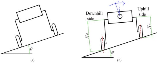
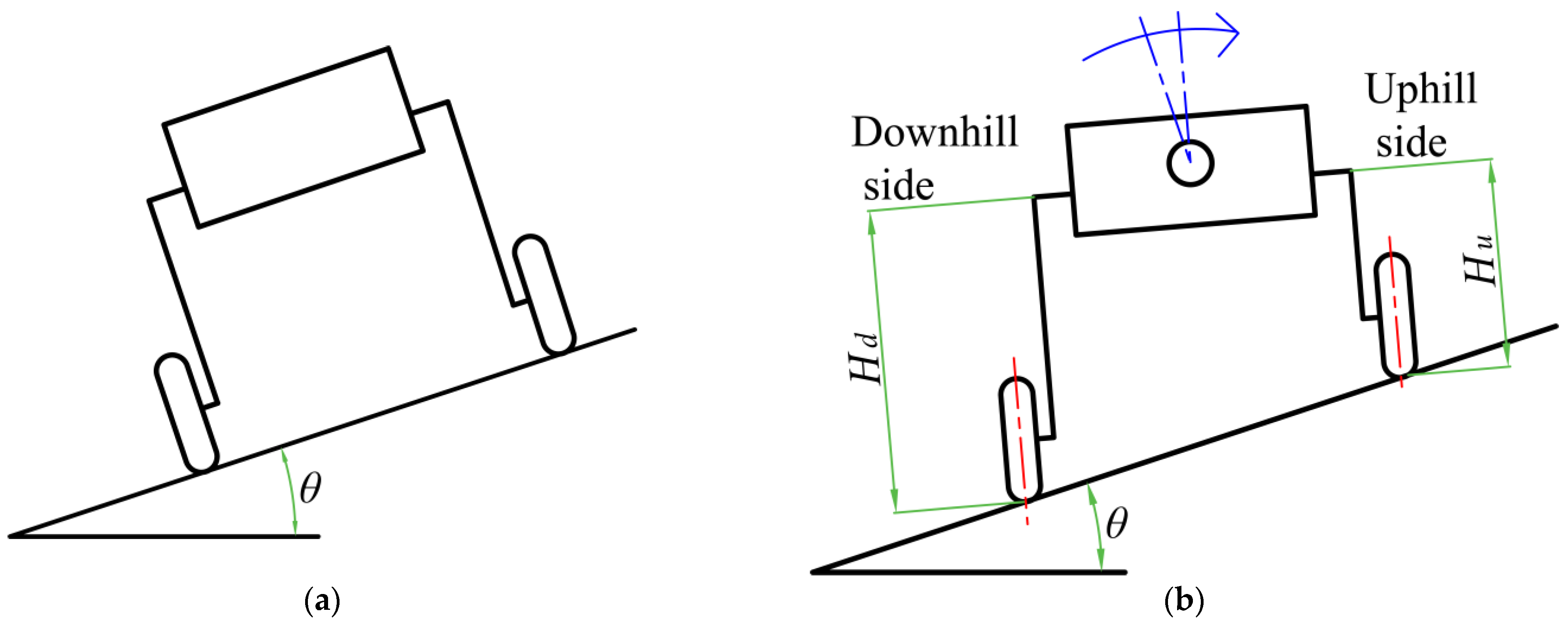
The principle of the attitude adjustment method is shown in Figure 1, which illustrates a tractor laterally traversing a slope of angle ; (a) is the initial state and (b) is the attitude adjustment state. By adjusting the COG heights on both the downhill and uphill sides ( and ), the angle of the tractor and its wheels can be changed. The roll angle of a tractor is adjusted by changing its attitude and configuration, thereby enhancing its mobility in accordance with complex terrain conditions.
Figure 1.
Attitude adjustment method: (a) initial state; (b) attitude adjustment.
For this attitude adjustment method, several assumptions are made to simplify the problem.
- The four wheels are assumed to be rigid, and tire non-linearity is neglected.
In real systems, tire non-linearity causes the wheel angle relative to the ground to change while raising or lowering one side [35]. Accordingly, this changes the track width. Therefore, with rigid wheels, the distance between the wheels is assumed to be constant during attitude adjustment.
- 2.
- The COG stays centered between the wheels during attitude adjustment.
With this attitude adjustment method, asymmetric geometry is introduced into the tractor configuration. As the masses on the downhill and uphill sides are approximately equal, the lateral shift of the COG is neglected.
2.1. Coordinate Systems
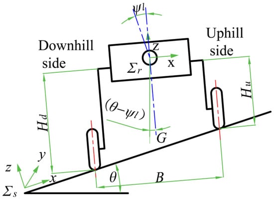
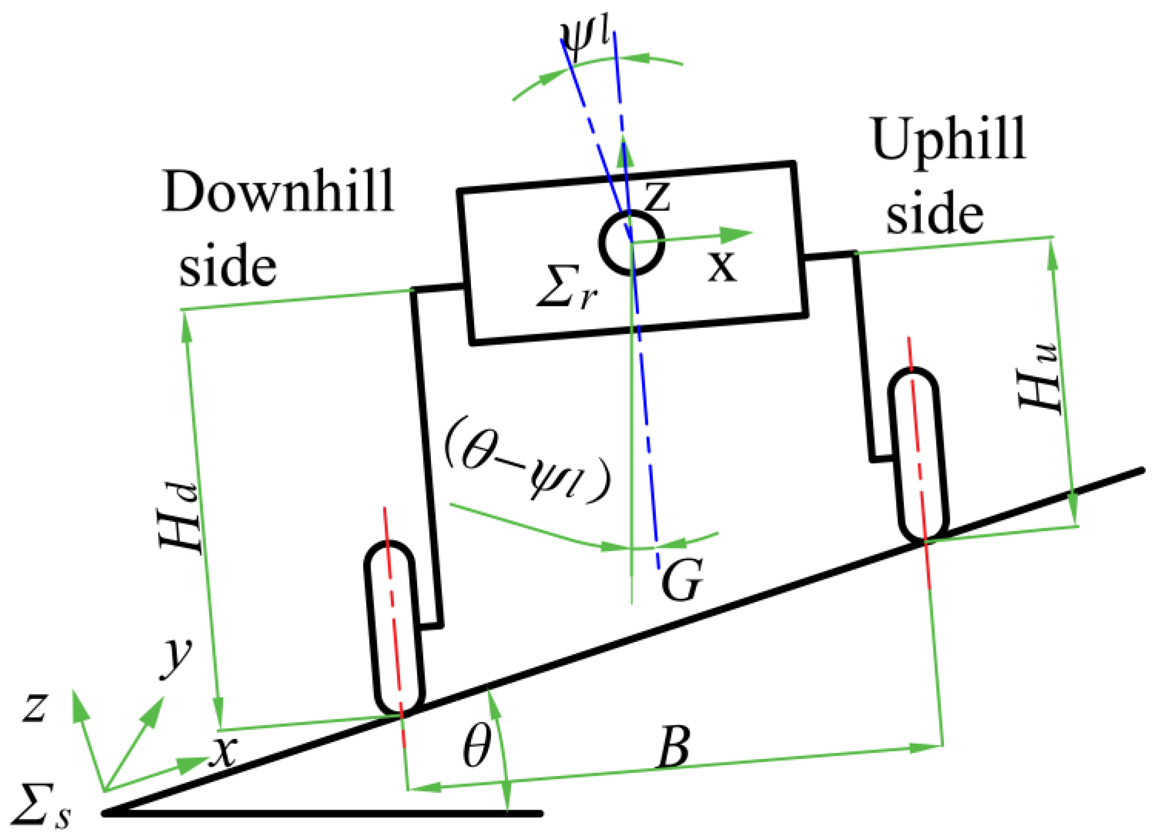
Here, two coordinate systems—the slope coordinate system and the tractor coordinate system—are defined. Figure 2 illustrates a tractor laterally traversing a slope of angle . By adjusting the COG (center of gravity) heights on both the downhill and uphill sides ( and ), the tractor and its wheels can be tilted at an angle against the slope ( positively increases in the uphill direction). As shown in Figure 2, the side slope coordinate system, , is defined as follows: denotes the uphill direction, denotes the desired traversing direction, and denotes the vertically upward direction against the slope surface, as a right-handed system. The tractor coordinate system, , is obtained through a rotation of about the axis with in the uphill direction.
Figure 2.
Definition of coordinate systems on side slope.
2.2. Tractor Configurations
As shown in Figure 2, the COG of the tractor is located at distances and from the downhill and uphill wheels along the axle, respectively. The tread (the distance between the two center planes of the wheels) of the tractor is B. The initial COG height is .
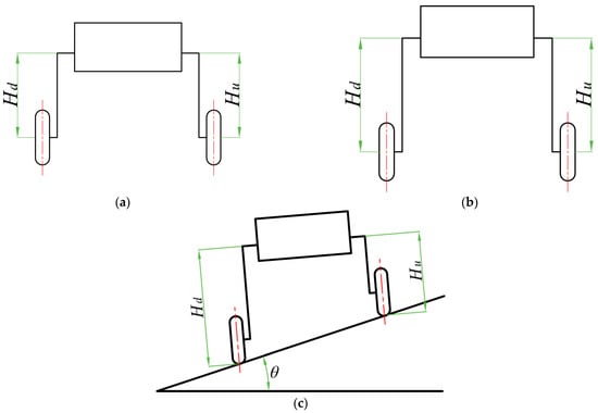
As shown in Figure 2, the individual wheel suspension travel can first be adjusted on each side. Therefore, the tractor can actively adjust its attitude by varying and on both sides.
- •
- Overall chassis height
As shown in Figure 3a,b, when the heights of the uphill and downhill sides are equal, the overall chassis height can be continuously and actively adjusted.
Figure 3.
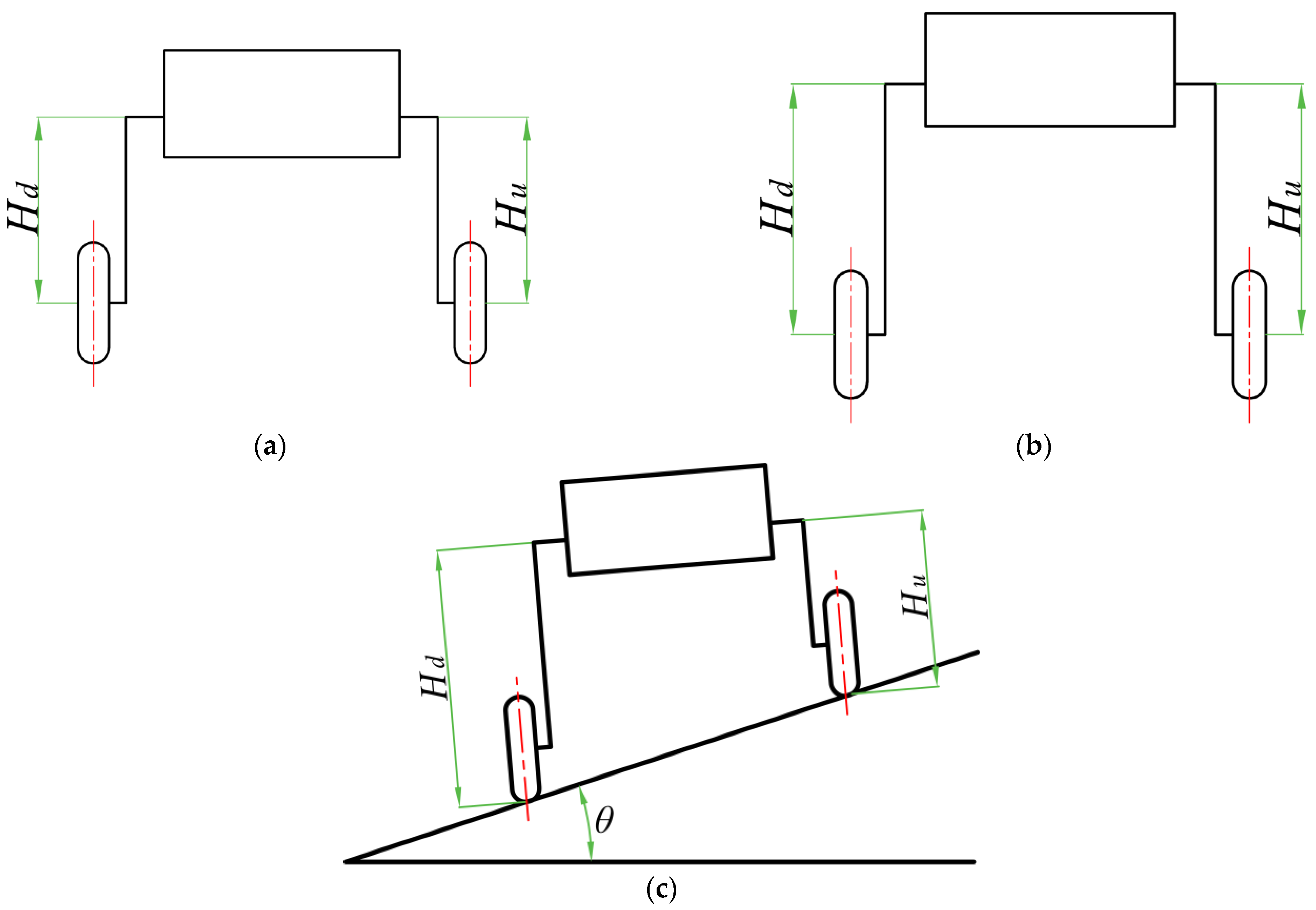
Tractor reconfiguration: (a) low ground clearance; (b) high ground clearance; (c) attitude adjustment. is the slope angle; and are the COG heights on the downhill and uphill sides, respectively.
Specifically,
When the COG height on both sides rises synchronously, the ground clearance of the tractor increases. When the COG height on both sides falls synchronously, the ground clearance of the tractor decreases.
- •
- Body roll angle adjustment
As shown in Figure 3c, when the heights of the uphill and downhill sides differ (i.e., when ), the roll angle of the tractor can be actively adjusted.
According to the proposed adjustment method, the tractor’s attitude adjustment angle is given by
denotes the roll angle and denotes the attitude adjustment angle of the tractor. The tractor can actively adjust its attitude while traversing a side slope with angle . Therefore, the roll angle of the tractor is given by
With this attitude adjustment method, the individual wheel suspension travel can first be adjusted. Then, the heights of both the uphill and downhill sides can be changed. In this way, the roll angle of the tractor changes. As shown in Figure 3, when the heights of the uphill and downhill sides are equal, the COG height can be continuously and actively adjusted. When the heights of the uphill and downhill sides differ, the roll angle of the tractor can be actively adjusted to enhance the tractor’s mobility.
3. Kinematic Model
For wheeled tractors using attitude adjustment methods, there are three different steering modes; namely, front-wheel, four-wheel, and articulated body steering. Kinematic models for these three steering modes are established in this study.
3.1. Front-Wheel Steering Mode
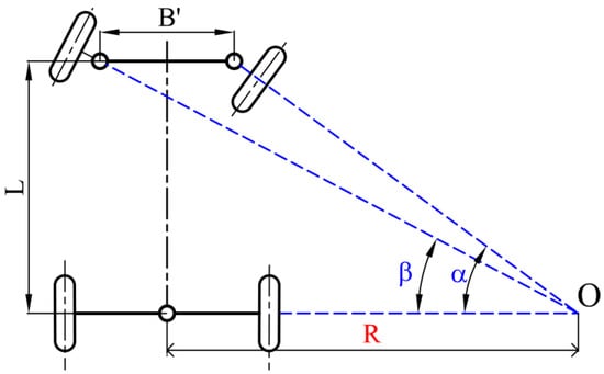
As shown in Figure 4, the turning radius R of the tractor is the distance between the turning center O and the center point of the drive axle. R is expressed as follows:
Figure 4.
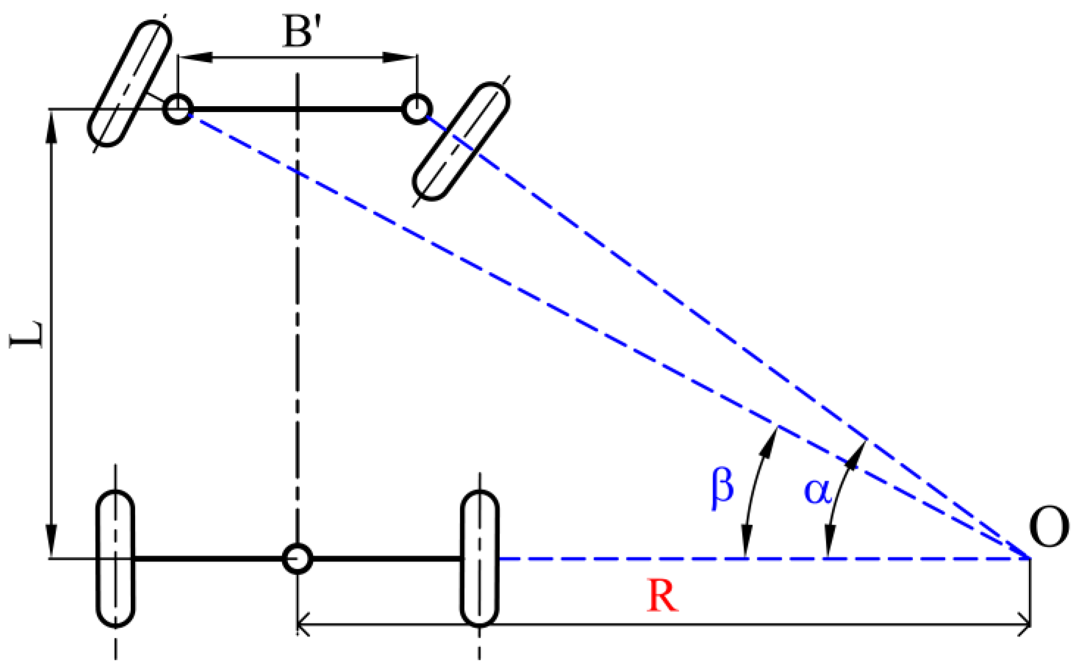
Front-wheel steering kinematics.
For front-wheel steering tractors, the deflection angles of the inner and outer wheels relative to the tractor body (denoted as and , respectively) are unequal. As shown in Equation (6), the relationship between and is
Therefore,
where is the distance between the vertical axes of the left and right steering knuckles, and L is the wheelbase of the tractor.
No matter what the turning radius is, the deflection angles and should be consistent with Equation (7).
3.2. Four-Wheel Steering Mode
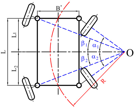
The four-wheel steering method is shown in Figure 5. When the front and rear wheels turn in opposite directions, its inner and outer wheels can drive along concentric circles with the same centers, but different radii.
Figure 5.
Four-wheel steering kinematics.
For a four-wheel steering tractor, the deflection angles of the front inner and outer wheels are and , respectively. Similarly, the deflection angles of the rear inner and outer wheels are and , respectively. As shown in Figure 5, the steering angles should simultaneously meet the following conditions:
The turning radius R of the tractor is the distance between the turning center O and the center point of the front or rear axles. When , the turning radius R is
When the inner turning angle reaches its maximum value, the minimum turning radius is obtained.
When , , and , the deflection angles of the inner and outer wheels relative to the tractor body are and , respectively. According to Equation (8), the relationships between these two angles are
- •
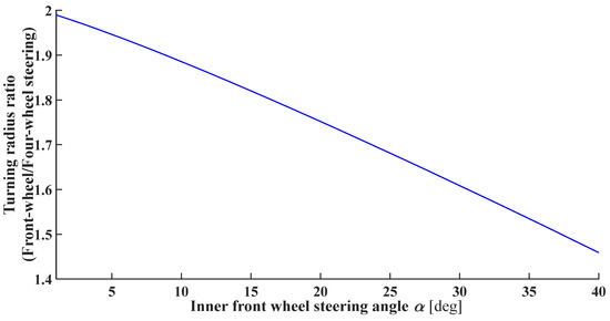
- The turning radius for the front-wheel and four-wheel steering methods is presented in Figure 6.Figure 6. Turning radius.
The steering radius for the front-wheel and four-wheel steering methods can be calculated using Equations (5) and (9), respectively. When and are kept constant, the turning radii can be compared.
Figure 6 shows the ratio of the turning radius of front-wheel steering to four-wheel steering when is 900 mm and is 1600 mm. The turning radius of front-wheel steering is larger than that of four-wheel steering. The turning radius of four-wheel steering is 50–70% of that of front-wheel steering. Therefore, the four-wheel steering method obtains a better turning radius.
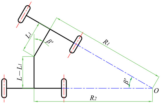
3.3. Articulated Body Steering Mode
As shown in Figure 7, an articulated tractor is basically composed of front “f” and rear “r” sections connected by a Degree of Freedom (DoF) joint. The DoF, the angle, is actuated and allows rotation around the yaw axis to let the tractor turn. is the wheelbase of the tractor, and is the axial distance from the rotation center to the front axle.
Figure 7.
Articulated body steering kinematics.
The angle is related to the circular trajectory radius R. As illustrated in Figure 7, the circular turning radii for the front and rear axles are given by
When , R can be written as follows:
4. Theoretical Analysis of Steering Stability
A tractor is subjected to various lateral external forces (e.g., turning centrifugal force, lateral wind force) when it is operating on a transverse slope, and is more susceptible to overturning and sliding under these working conditions. Therefore, lateral stability under these conditions is evaluated based on the critical slope angle and steering speed associated with lateral overturning.
The main purpose of this study is to propose a model for a tractor equipped with an attitude adjustment mechanism for use during steering. The model represents the relationship between the tractor’s configuration and its lateral stability during steering. Additionally, by adjusting the COG heights on both sides, the tractor’s attitude and configuration can be changed. Based on this attitude adjustment method, models are developed for front-wheel, four-wheel, and articulated body steering modes. These models represent the relationship between the input (configuration, attitude, or COG heights on both uphill and downhill sides) and the output (instability evaluating indicators).
In this section, we make several assumptions to simplify this problem, as follows:
- The tractor is equipped with four rigid wheels, and the distance between the wheels is assumed to be constant during attitude adjustment;
- The tractor travels along a flat lateral slope;
- The tractor’s turning speed is slow, and it operates in a steady state;
- The roll angle of the tractor changes by shifting the vertical positions of the wheels relative to the main body while fixing the pitch angle;
- The dynamic response characteristics of hydraulic and electromechanical actuators, including response time and actuation latency, are neglected.
4.1. Model of Tractor Steering on Transverse Slope
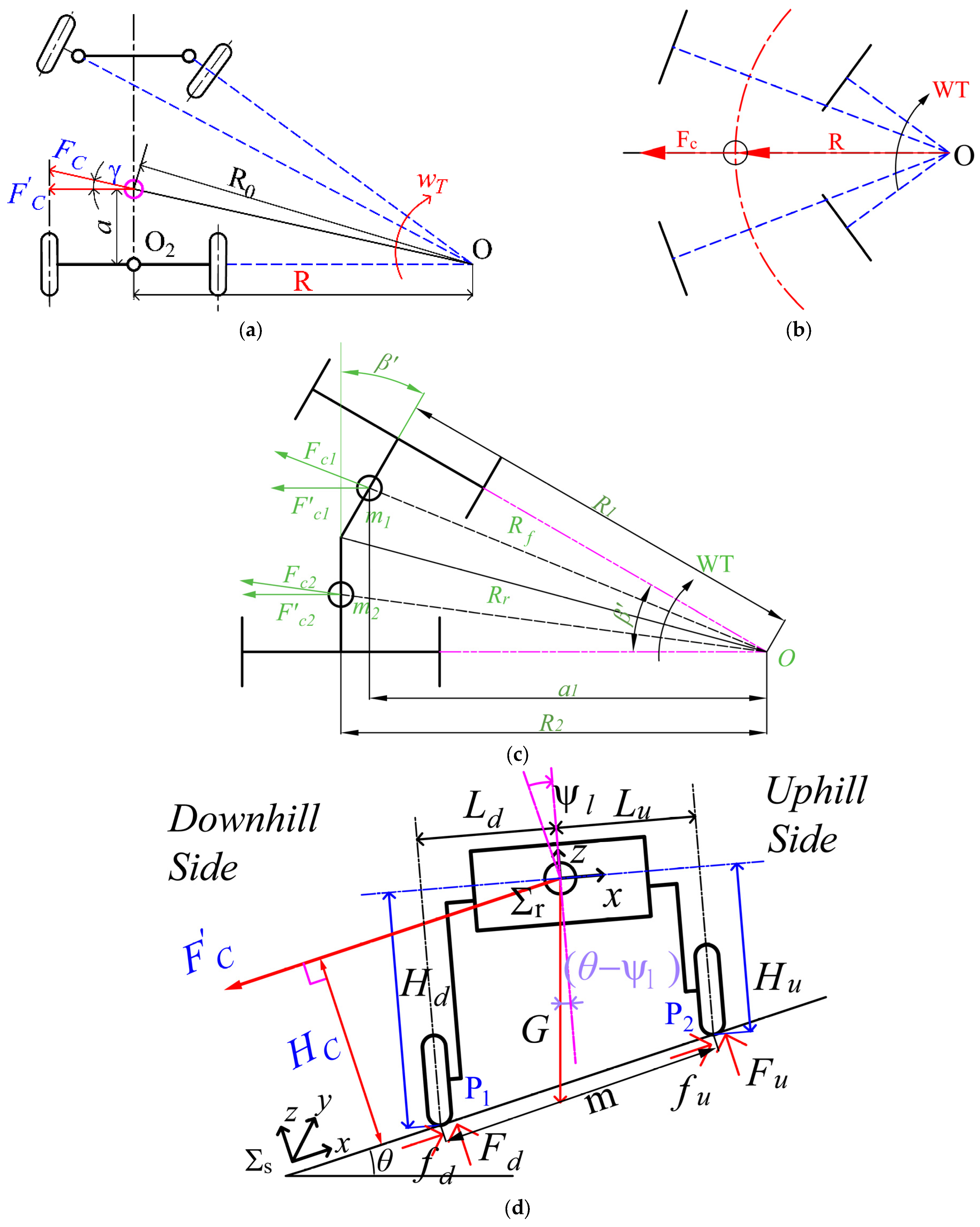
Figure 8 presents a force diagram of a wheeled tractor turning steadily towards the uphill side of a transverse slope. Under this working condition, the external forces that contribute to overturning include the vehicle weight moving in the cross-slope direction and the centrifugal force generated by the vehicle steering in the slope direction.
Figure 8.
Force diagram of vehicle turning steadily towards uphill side of transverse slope: (a) front-wheel steering; (b) four-wheel steering; (c) articulated body steering; (d) force diagram.
4.1.1. Centrifugal Force
The centrifugal force is as follows:
where is the weight of the tractor; is the gravitational acceleration; is the angular velocity; is the linear velocity; and is the turning radius at the vehicle’s COG.
A tractor can adjust its posture to enhance its mobility. Mathematical models of tractors with front-wheel, four-wheel, and articulated body steering are established to evaluate the steering stability of tractors equipped with an attitude adjustment mechanism under the three steering modes.
- Front-wheel steering:
This centrifugal force can be divided into two parts: vertical and lateral force components. The vertical component redistributes the vertical load of the tractor, and the lateral component contributes to lateral overturning. As shown in Figure 8a, the lateral force component is given by
Based on Equation (14), rearrangement yields
where , the average driving speed when the vehicle turns.
- 2.
- Four-wheel steering
As shown in Figure 8b, the lateral force component is given by
- 3.
- Articulated body steering
As shown in Figure 8c, the lateral force component is distributed between the front and rear parts.
The lateral force component of the front axle is given by
where is the horizontal distance between the front axle’s COG and rotation center, is the turning radius of the front axle, and is the gravity of the front axle.
The lateral force of the rear axle is given by
where is the distance between the rear axle’s COG and rotation center, and is the gravity of the rear axle.
Therefore, the lateral force component of the rear axle is given by
where is the turning radius of the rear axle.
The resultant lateral force components at the front and rear axles can be obtained based on Equations (18) and (20).
When ,
The turning radius of the rear axle is described in Equation (12).
Assuming that the center of mass of the front axle is located at its midpoint, and , Equation (13) can be rearranged to obtain the lateral force component, as follows:
Thus, the formulas for the components of centrifugal force along the transverse direction are obtained for the front-wheel, four-wheel, and articulated body steering modes, respectively. According to Equations (15), (17), and (22), with increasing velocity and a decreasing steering radius , the lateral component of centrifugal force significantly increases.
4.1.2. Force Analysis
As shown in Figure 8, the tractor’s COG is located at distances and from the uphill and downhill wheels, respectively, along the direction and at and from those wheels along the axle. Since the wheels are assumed to be rigid bodies, tire non-linearity is neglected. The wheel angle relative to the ground is also neglected. Therefore, and are assumed to be constant during adjustment. The track width is the sum of and , which is also constant, whereas and vary with the attitude adjustment angle . Forces acting on the front and rear wheels are assumed to be equivalent. Changes in tire characteristics caused by load variations and the effects of the aligning moment are neglected.
The attitude adjustment angle is described in Equation (3). The roll angle of the tractor is described in Equation (4).
Equations of motion can be obtained for the contact points on the downhill and uphill sides based on the model in Figure 8, as follows:
where is the lateral component of centrifugal force; and are the normal forces acting on the downhill wheel and uphill wheels, respectively; m is the distance between points P1 and P2; and is the moment of force from the COG to the contact point.
In addition, , .
Equation (23) yields the normal forces acting on the downhill and uphill wheels, respectively:
where and .
4.1.3. Moment of Force
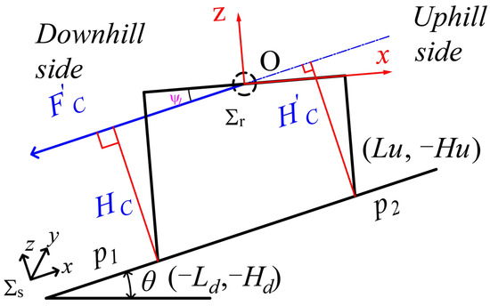
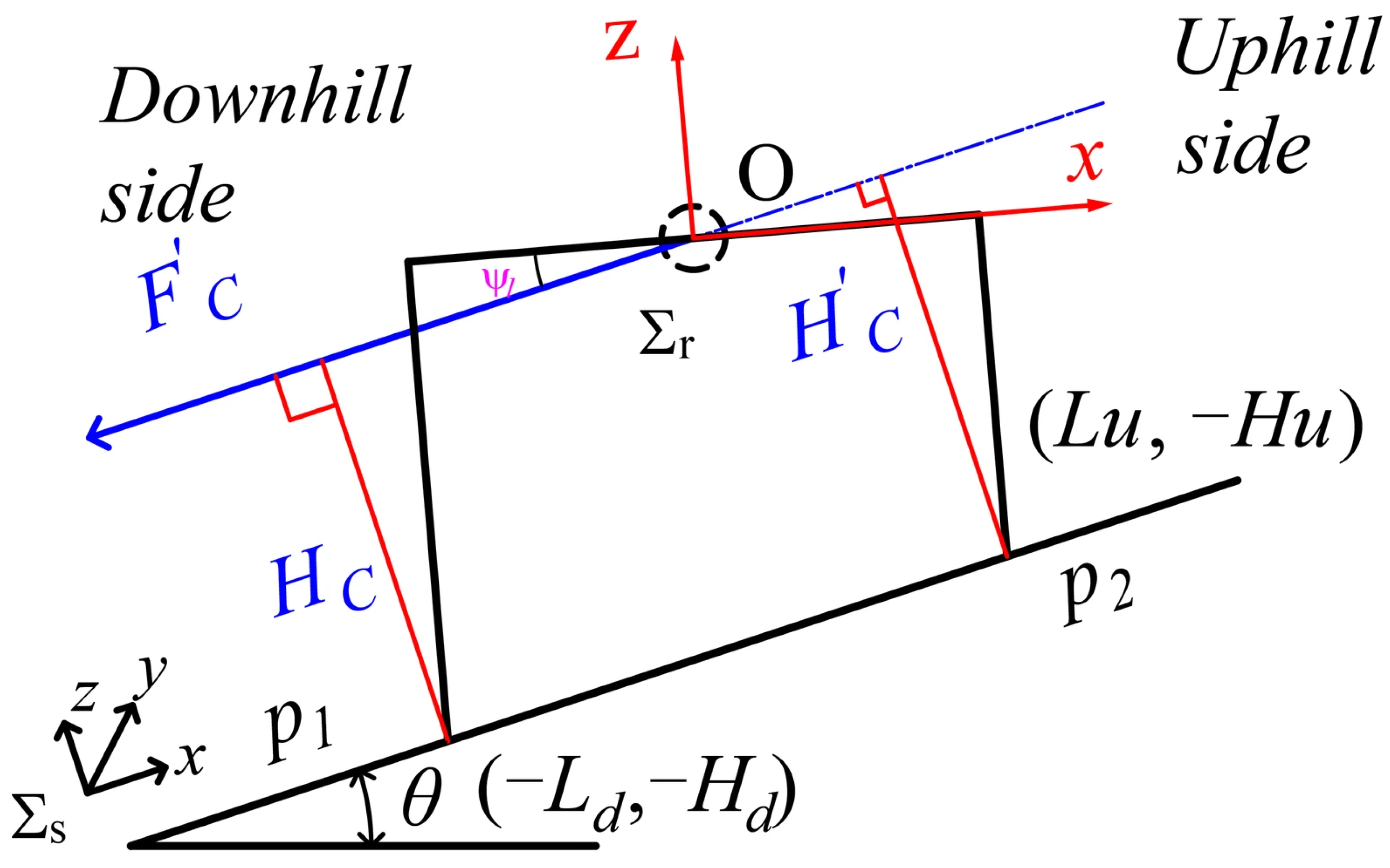
As shown in Figure 9, is the tractor coordinate system, which is established in Section 2.1. is achieved by a rotation of about the axis, with in the uphill direction. In , the line of action of the lateral force component, , is given by
where is the attitude adjustment angle of the tractor and , which refers to Equation (3).
Figure 9.
Diagram of moment of force from COG to contact point.
The contact points between the ground and the downhill and uphill wheels are and , respectively. The coordinates of these two points in the tractor coordinate system, , are as follows:
The moments of force of these two points about are calculated as follows:
Since , and are equal.
Furthermore, since , we have that , where is the wheel track. The moment can be obtained by rearrangement, as follows:
When ,
where is the initial COG height.
When the COG rises or falls synchronously, ,
where is the COG height after adjusting.
Equation (28) is used to calculate when a tractor with the attitude adjustment mechanism actively adjusts its roll angle.
Therefore, the moment is a function of and , depending on the specific attitude adjustment mode.
4.2. Lateral Slide Instability
Slip occurs when the lateral force exceeds the friction force at the ground. As shown in Figure 8, when a tractor slides on side slopes,
Additionally,
where denotes the ground adhesion coefficient.
Substituting Equation (31) into the expression yields
According to Equation (24),
where
Therefore,
where .
Substituting Equation (36) into Equation (31) yields
Under front-wheel steering conditions, substituting the expression for the lateral force component from Equation (16) into Equation (37) yields
When the slope angle is 0°, the critical sliding speed occurring on level ground is
When the turning speed is 0, the critical sliding angle under straight-line operation is
The critical sliding angle of the tractor, , can be obtained after arrangement as
where is the critical sliding angle under zero steering condition, .
The critical sliding speed of the tractor, , can be obtained after rearrangement as
where .
4.3. Lateral Overturning Instability
Rollover will occur if either of the tires loses contact with the ground (the contact force falls to zero).
Under straight-line driving conditions with no centrifugal force, the critical overturning angle of the tractor is
Under steering conditions, when , Equation (24) becomes
Rearranging Equation (44), the roll angle can be obtained using Equation (4), as follows:
where .
4.3.1. Critical Overturning Angle
Based on Equation (45), after arrangement,
Solving for gives
The critical instability angle of the tractor, , can be obtained after arrangement as follows:
Hence, the expression of the moment of force, , can be found in Equation (48). Under front-wheel steering conditions, the lateral force component is given by Equation (16).
Substituting and into Equation (27), the critical instability angle is given by
where and can be changed by the attitude adjustment mechanism on the uphill and downhill sides, respectively; is the turning radius; and is the average driving speed when the vehicle turns.
4.3.2. Critical Overturn Steering Speed
Given the lateral slope angle and steering radius, the corresponding critical steering speed of a tractor equipped with an active attitude adjustment mechanism can be calculated for operation on the side slope.
The critical steering speed is obtained by substituting the centrifugal force into Equation (45), where is given by Equation (16) in the front-wheel steering mode:
where is obtained using Equation (4) and is obtained using Equation (28).
Based on the above equations, the critical overturn steering speed (see (Equation (50)) can be presented as follows:
where and are the COG heights on the downhill and uphill sides, respectively; is the slope angle; and is the turning radius.
When a tractor turns suddenly at high speed, the speed is high and the turning radius is small. This tractor can overturn even on flat ground. Under this working condition, if a tractor does not adjust its posture, where and , the critical instability speed is given by
In other words, when a tractor is operating on flat terrain and the turning radius R is certain, its steering speed cannot be larger than ; otherwise, it will overturn on flat terrain.
When a tractor adjusts its posture on flat terrain, the critical speed can be expressed as a function of the active inputs of the adjustment mechanisms on both the uphill and downhill sides as the variables (input into Equation (51)). Even when working on flat terrain, a tractor can actively adjust its posture to increase the critical steering speed.
4.4. Lateral Stability Under Level Attitude Conditions
A tractor equipped with the attitude adjustment method described in Section 2 can adjust its attitude. This method also can level a tractor’s attitude on side slopes.
When a tractor levels its attitude while operating on a side slope, its roll angle is zero. According to the equation of the roll angle, (Equation (4)), this condition can be expressed as
Therefore, the COG heights on the uphill and downhill sides need to satisfy the following relationship:
where is the slope angle and is the tread (the distance between the two center planes of the wheels) of the tractor.
Overall, by changing the COG heights on both the uphill and downhill sides, a tractor’s configuration/roll angle can be adjusted. Therefore, the lateral steering stability criteria, including the critical instability overturning angle and steering speed, can be obtained by employing the COG heights on both the uphill and downhill sides as the input variables.
5. Case Studies and Results
This section investigates the relationship between the active input and lateral overturn stability during steering. Lateral steering stability is evaluated in terms of both the critical instability angle and steering speed. A tractor utilizing the attitude adjustment mechanism is used as an example.
5.1. Attitude Adjustment Mechanism
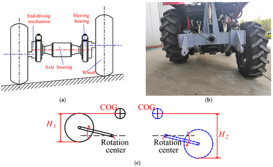
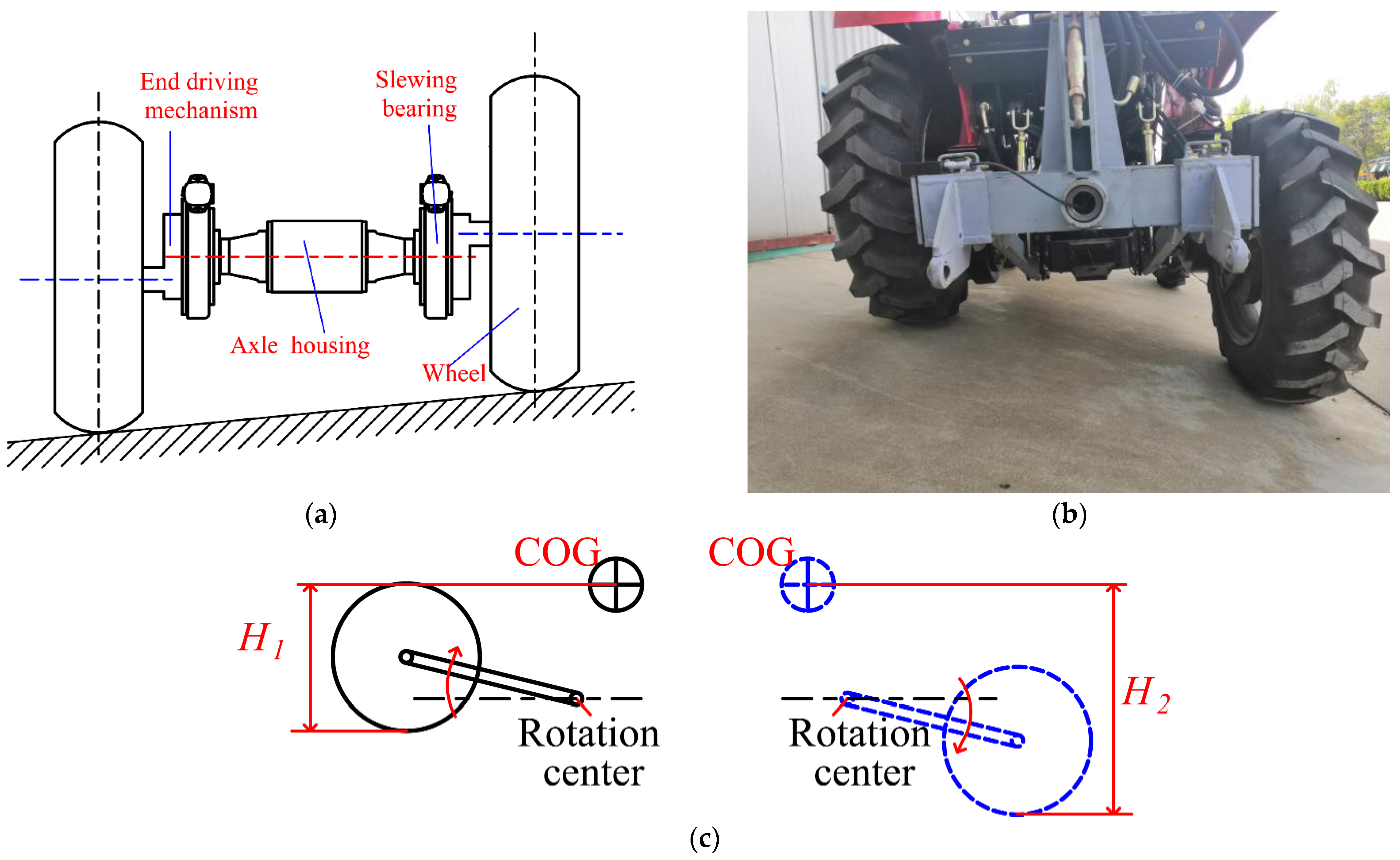
As shown in Figure 10, this tractor (Wuzheng Group, Rizhao, Shandong, China) is composed of an active rear axle, passive front axle, and a main body, enabling it to adjust its attitude while operating on a side slope.
Figure 10.
Attitude adjustment mechanism. (a) Simple model; (b) practical model; (c) scheme of working principle showing attitude adjustment.
5.1.1. Active Rear Axle
Based on the attitude adjustment method, the height of each side is adjusted by a specific attitude adjustment mechanism. A wheeled tractor can adjust its posture using the attitude adjustment mechanism mounted on the rear axle.
As shown in Figure 10, the rear axle has a symmetrical structure, where each side comprises a slewing bearing, an end-drive mechanism, and a wheel. The wheel is fix-connected to the end-drive mechanism [34]. By changing the input of the slewing bearing, the end-drive mechanism can rotate around the axis of the axle housing. Then, the height of each side can be adjusted.
As shown in Figure 10, this tractor can offset the height difference between the two sides. Thus, the tractor can adjust its roll angle to enhance its stability under complex terrain conditions.
5.1.2. Passive Front Axle
To achieve attitude adjustment for hilly mountain tractors operating on side slopes, a rear drive axle capable of actively adjusting the body’s attitude is required, along with coordinated adjustment of the front drive axle.
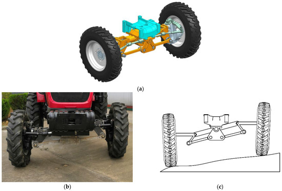
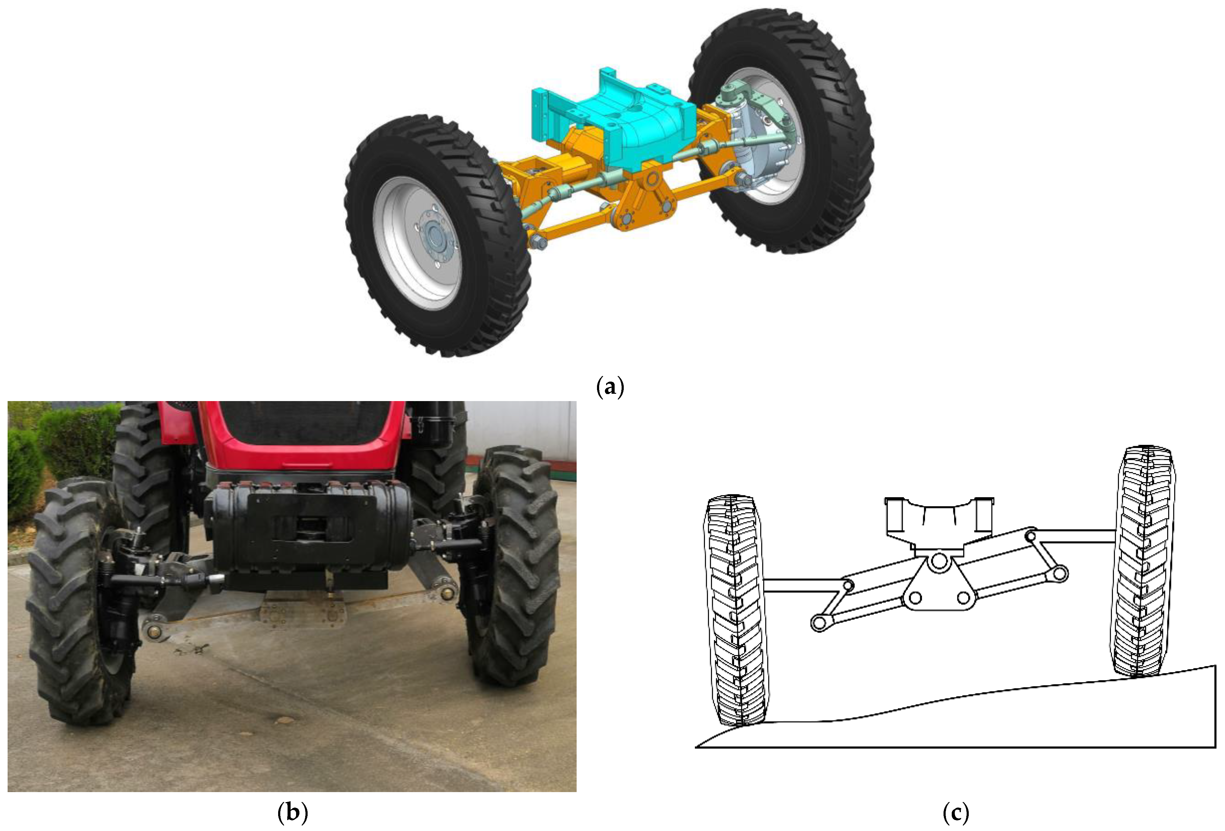
As shown in Figure 11, the front axle is a steer-drive axle that integrates three functions simultaneously: steering, driving, and attitude adjustment [34]. Steering is achieved through the steering trapezoidal mechanism. For the attitude adjustment function, the passive front axle is composed of two symmetric four-bar linkages, one on each side, with one degree of freedom. Standard tractors use a front axle center pivot that reduces stability to a triangle rather than a four-point linkage. Although the traditional axle structure is simple, it fails to achieve cooperative attitude adjustment with the rear axle under large-gradient lateral slope conditions. For the four-point front axle, the angle between the front wheels and the ground can be passively adjusted. Given the rotation angle of any component of the attitude adjustment mechanism in the front axle, the remaining rotation angles can be determined. This degree-of-freedom characteristic ensures that the tractor maintains four-wheel contact in real-time without active control. Accordingly, by combining this front axle with the active rear axle, active attitude method of the tractor can be achieved. The center-of-gravity position and posture of the tractor are modified to improve its lateral stability during operation on slopes with large inclination angles.
Figure 11.
Passive front axle: (a) 3D model; (b) practical model; (c) schematic diagram.
5.1.3. Entire Tractor
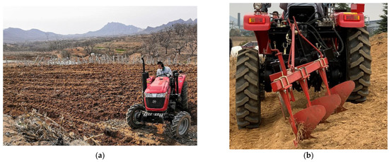
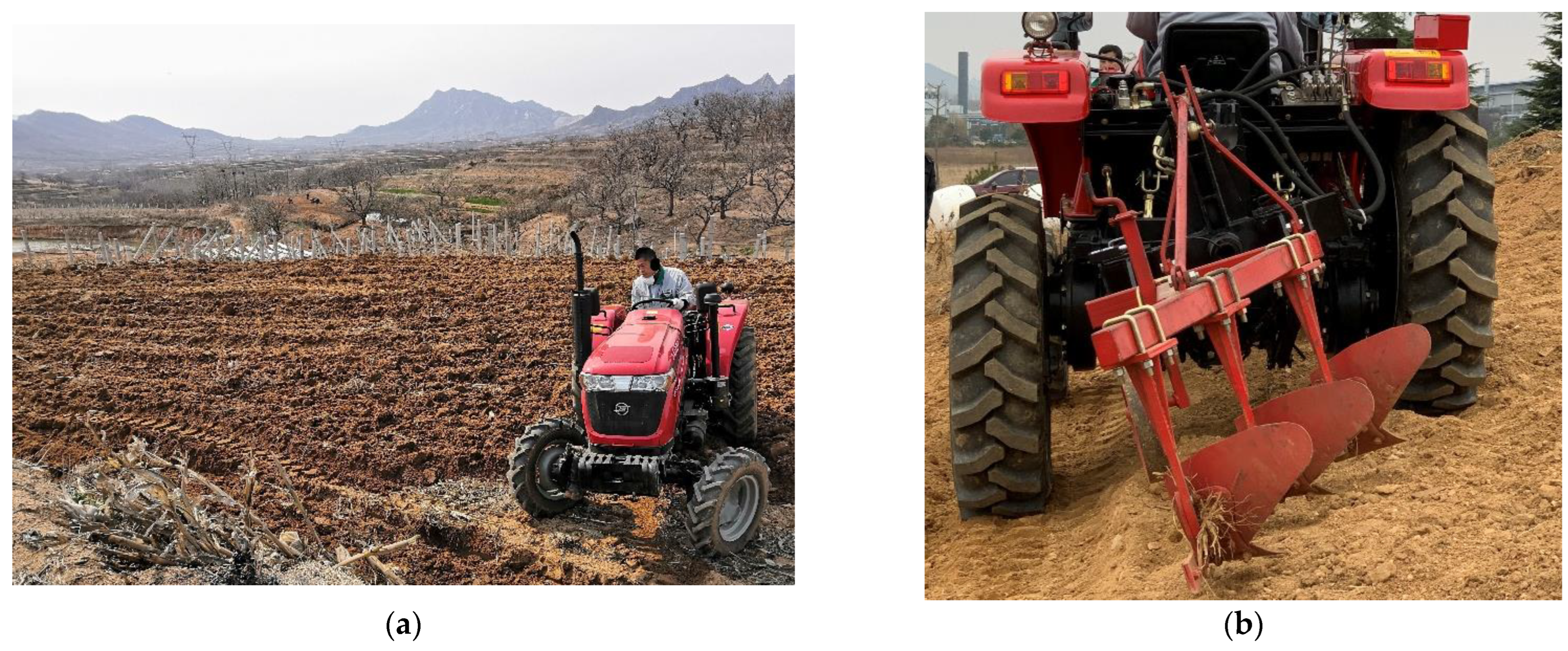
As shown in Figure 12, field tests were conducted on a tractor prototype capable of performing traveling, steering, and other functions. This tractor can also perform attitude adjustment. With active adjustment applied to the swing mechanism of the rear axle, the front axle adjustment mechanism moved passively to achieve attitude adjustment on slope terrain while maintaining contact between all four wheels and the ground. The experimental results from multiple tests show that by collecting ground condition information and adopting motion control to actively regulate the swing angle of the tractor rear axle, height-level operation can be achieved on slopes with inclination angles of up to 15°.
Figure 12.
Entire tractor: (a) practical model; (b) attitude adjustment model.
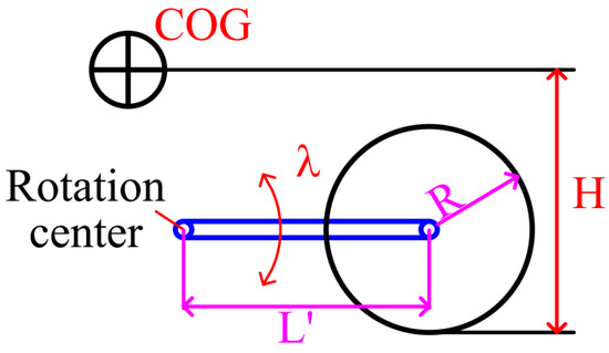
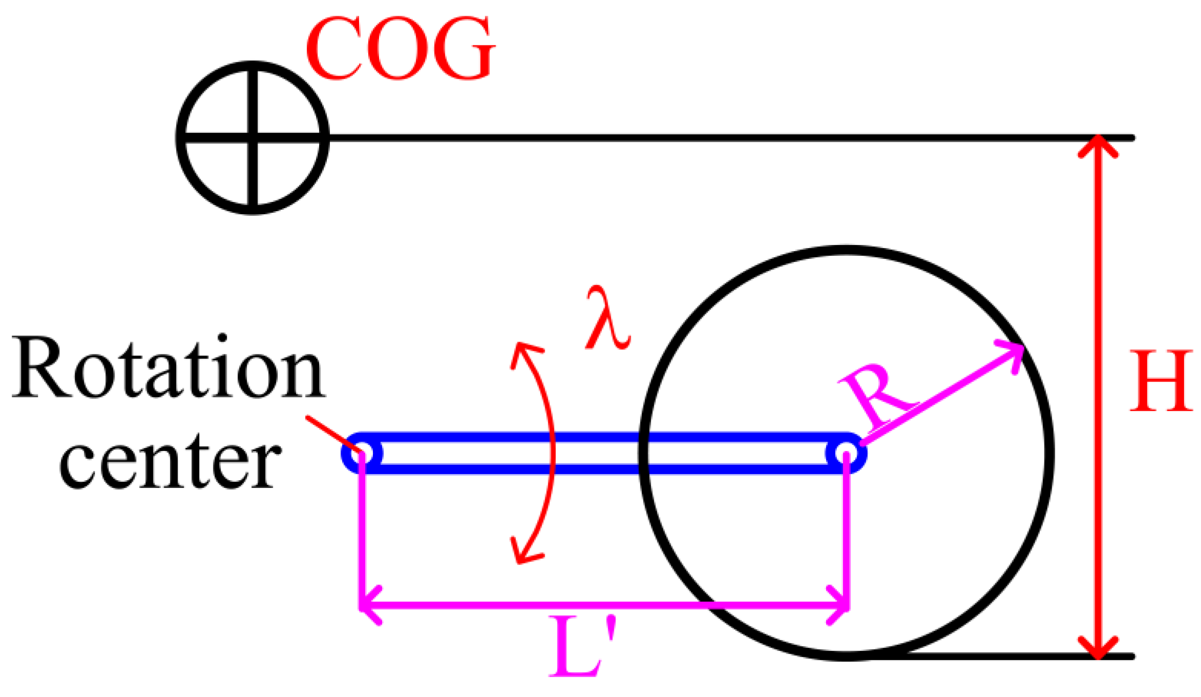
With the rear axle driven actively and the front axle following passively, the attitude of the entire tractor can be adjusted by actively varying the angle and orientation of the rear-axle attitude adjustment mechanism. The parameter model of this attitude adjustment is shown in Figure 13. The COG height is given by
where is the initial COG height; is the distance between the rotation center and wheel center; and is the attitude adjustment angle of the rear axle, . can be actively adjusted, whereas and are both constant values.
Figure 13.
Parameter model of attitude adjustment mechanism.
Theoretically, , the adjustment angle of the rear-axle attitude adjustment mechanism, ranges from 0° to 90°. At an adjustment angle of 90°, the wheel mechanism is oriented fully vertically. The rear-wheel attitude adjustment mechanism ensures power transmission during attitude adjustment. Hence, to ensure mechanism motion safety, the actual angle is limited to 0–80°.
To investigate the effectiveness of the attitude adjustment method in preventing rollover, a typical model was developed using the MATLAB software, version 2021. The model was solved using the MATLAB solver, and measurements of all parameters were obtained through simulation using the model established in Section 4. In addition, key parameter values of a representative tractor were employed to accurately simulate a tractor rollover accident. The reference values for the simulation are listed in Table 1.
Table 1.
Tractor parameter values.
The critical overturning slope angle and steering speed are discussed. The lateral steering stability under the level attitude mode is also described.
5.2. Critical Instability Angle
In this study, numerical turning simulations were conducted to investigate the critical slope angle at which a tractor overturns and to evaluate the effect of the attitude adjustment method on steering stability. A general mathematical model was formulated for the representative tractor. This case study employed the simplest method, where the downhill-side wheels were lowered and the uphill-side wheels were raised by the same amount. Accordingly, the COG heights on the uphill and downhill sides are given by
where is the initial COG height; is the distance between the rotation center and the wheel center; and is the attitude adjustment angle of the rear axle, with . can be actively adjusted, whereas both and remain constant.
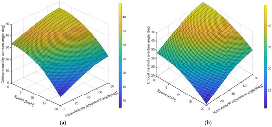
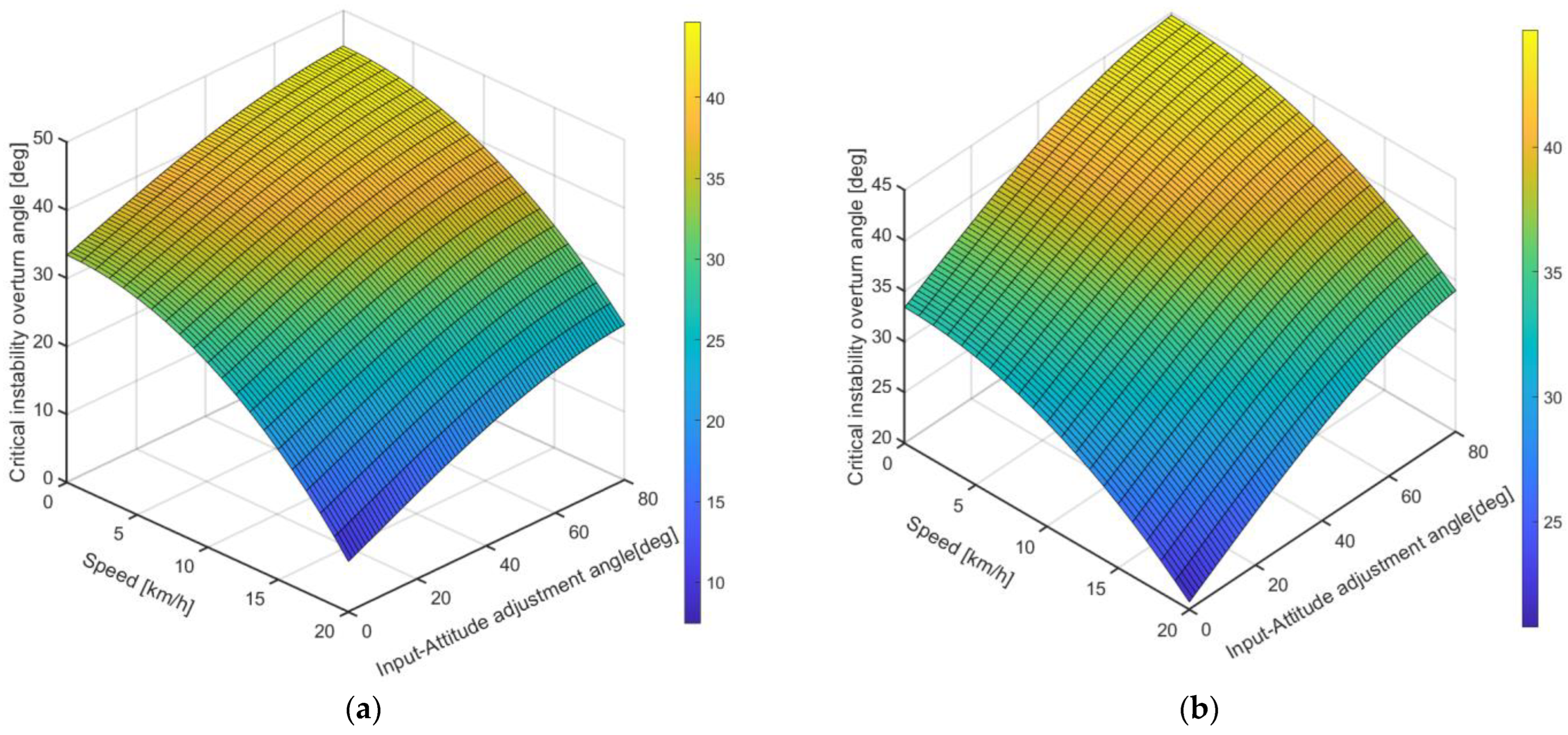
In the simulation, two types of turning were observed, with the turning radius set to 6 m and 12 m, respectively. The COG heights on the uphill and downhill sides are expressed as functions of the attitude adjustment angle of the rear axle, as given in Equation (56), with the speed ranging from 0 to 20 km/h. The critical instability overturning angle can then be calculated by substituting Equation (56) into Equation (49). The critical overturning slope angle, , can be obtained with Equation (49), using the attitude adjustment angle of the rear axle and the turning speed as independent variables. Taking steering into consideration, the effect of active input on the lateral steering overturning angle is shown in Figure 14.
Figure 14.
Critical instability overturn angle for lateral steering stability: (a) turning radius of 6 m; (b) turning radius of 12 m.
As shown in Figure 14a, the turning radius is 6 m. As indicated, the critical instability overturn angle () increases with an increasing active rotation angle (), and decreases with an increasing steering speed (). When , increases from 33.42 to 44.69; when , increases from 31.85 to 43.36; when , increases from 27.13 to 39.35; when , increases from 19.15 to 32.58; when , increases from 7.43 to 22.79.
As shown in Figure 14b, the turning radius is 12 m. As indicated, the critical instability overturning angle () increases with an increasing active rotation angle (), and decreases with an increasing steering speed (). When , increases from 33.42 to 44.69; when , increases from 32.63 to 44.03; when , increases from 30.28 to 42.02; when , increases from 26.34 to 38.67; when , increases from 20.76 to 33.95.
Overall, the critical instability overturn angle () decreases as the turning radius () decreases or the steering speed () increases. is an evaluation indicator, and it falls within the normal range. However, under real operating conditions, tractor overturning may be induced by rapid steering, ground variability, and surface changes. Therefore, the predicted instability slope angle does not represent the normal operating range of agricultural tractors. A tractor equipped with an attitude adjustment mechanism can increase its lateral steering stability. Specifically, this can be achieved by actively adjusting the rotation angles of the rear axle on both sides. In addition, when the rotation angle increases from 0 to 80, the critical instability overturning angle () can increase by more than 20%.
5.3. Critical Steering Speed
In this study, a numerical turning simulation was conducted to investigate the critical steering speed when a tractor overturns and to evaluate the effect of the attitude adjustment method on the steering stability. A more general mathematical model was formulated for the representative tractor. This case study employed the simplest attitude adjustment method, as given in Equation (56).
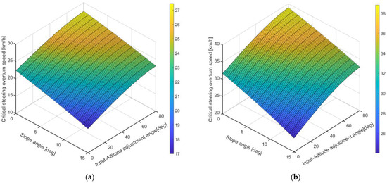
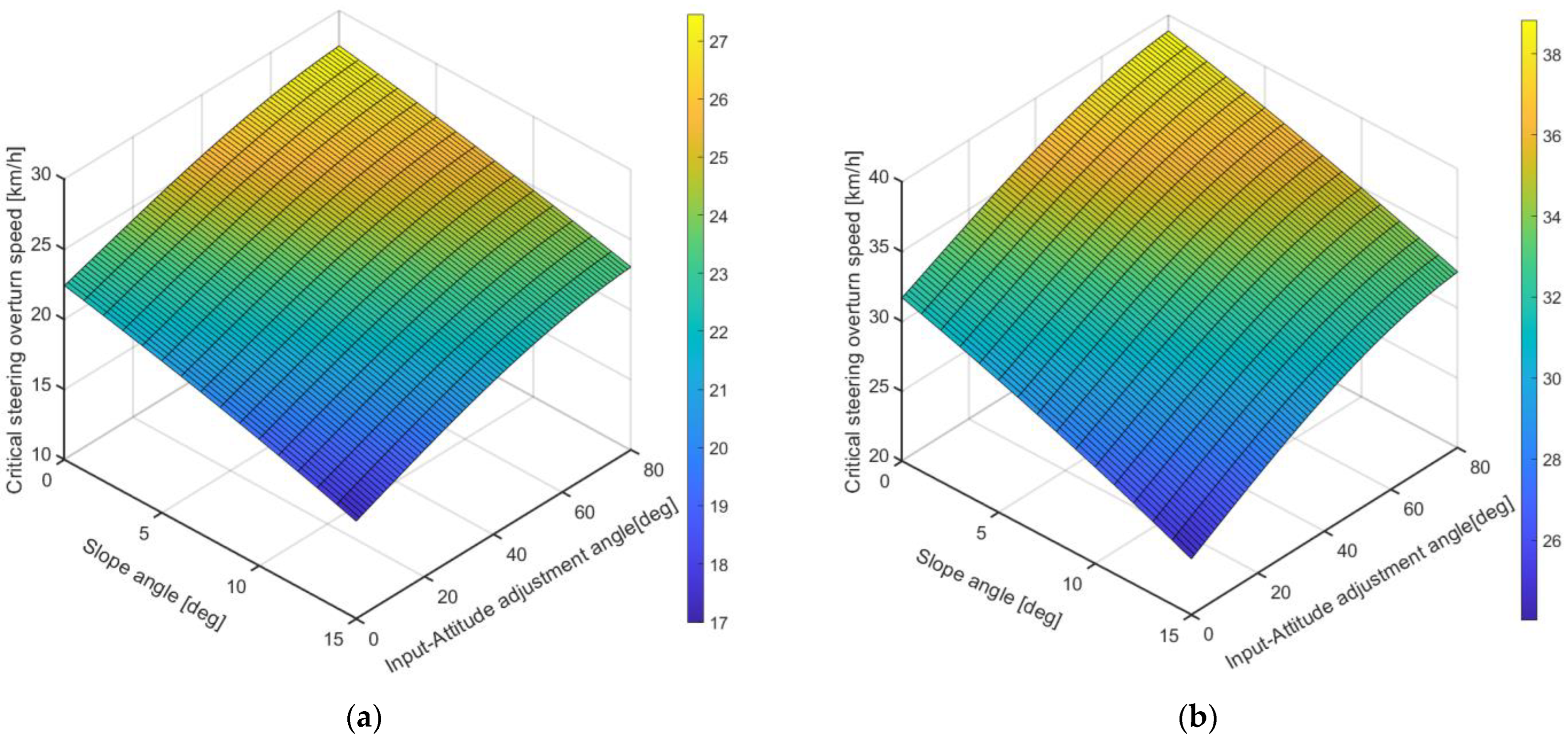
In the simulation, two turning scenarios were observed, with the turning radius set to 6 m and 12 m, respectively. The COG heights on the uphill and downhill sides are expressed as functions of the attitude adjustment angle of the rear axle, as shown in Equation (56), with the slope angle ranging from 0 to 15 deg. The critical instability overturning speed can then be calculated by substituting Equation (56) into Equation (51). The critical overturning speed, , can be obtained with Equation (51), with the attitude adjustment angle of the rear axle and the slope angle taken as independent variables.
The effect of active input on the critical steering speed is shown in Figure 15. Overall, when a tractor traverses on a slope, the tractor’s critical steering speed () increases with the active input (rotation angle of the rear axle, ). In addition, under the same turning radius (), the tractor’s critical steering speed () decreases as the slope angle increases. is an evaluation indicator, and it falls within the normal range. However, under real operating conditions, tractor overturning may be induced by quick steering, ground variability, and surface changes. Therefore, the predicted instability steering speed does not fall within the normal operating range of agricultural tractors. According to the general comparison in Figure 15a,b, when the turning radius () increases, the tractor’s critical steering speed () increases.
Figure 15.
Critical steering speed for lateral stability: (a) turning radius of 6 m; (b) turning radius of 12 m.
Generally, attitude adjustment is an effective way to enhance a tractor’s steering speed when it works on a side slope.
5.4. Level Attitude Case
The level configuration can be adjusted when the side slope angle is in the range of 0–15. In the simulation, two types of turning were observed: turning without attitude adjustment and turning with a level attitude. The turning radius was set to 6 m and 12 m, respectively.
In the initial state, the tractor turned without attitude adjustment, and the COG heights on the downhill and uphill sides were equal. Then, the critical overturning speed was obtained by substituting into Equation (51), as shown in Section 4.3.
In the level attitude state, the COG heights of the uphill and downhill sides satisfied the relationship given in Equation (54) in Section 4.4. In this case, the tractor started from its initial state, with the COG at the lowest position, and its posture was leveled by raising the COG height on the downhill side. This attitude adjustment method was used to level the tractor’s attitude:
where is the initial COG height, is the tread, and is the slope angle.
The critical instability overturning angle can then be calculated by substituting Equation (57) into Equation (51). In this case, was 809 mm, was 1280 mm, and the slope angle was between 0 and 15 degrees. The critical overturning speed, , was obtained in both the initial state and level attitude modes.
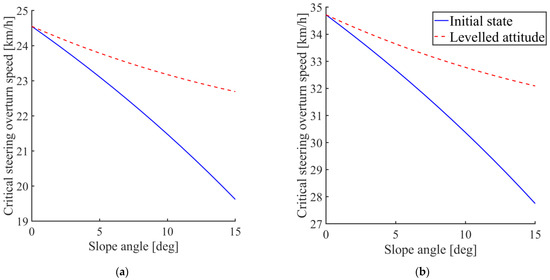
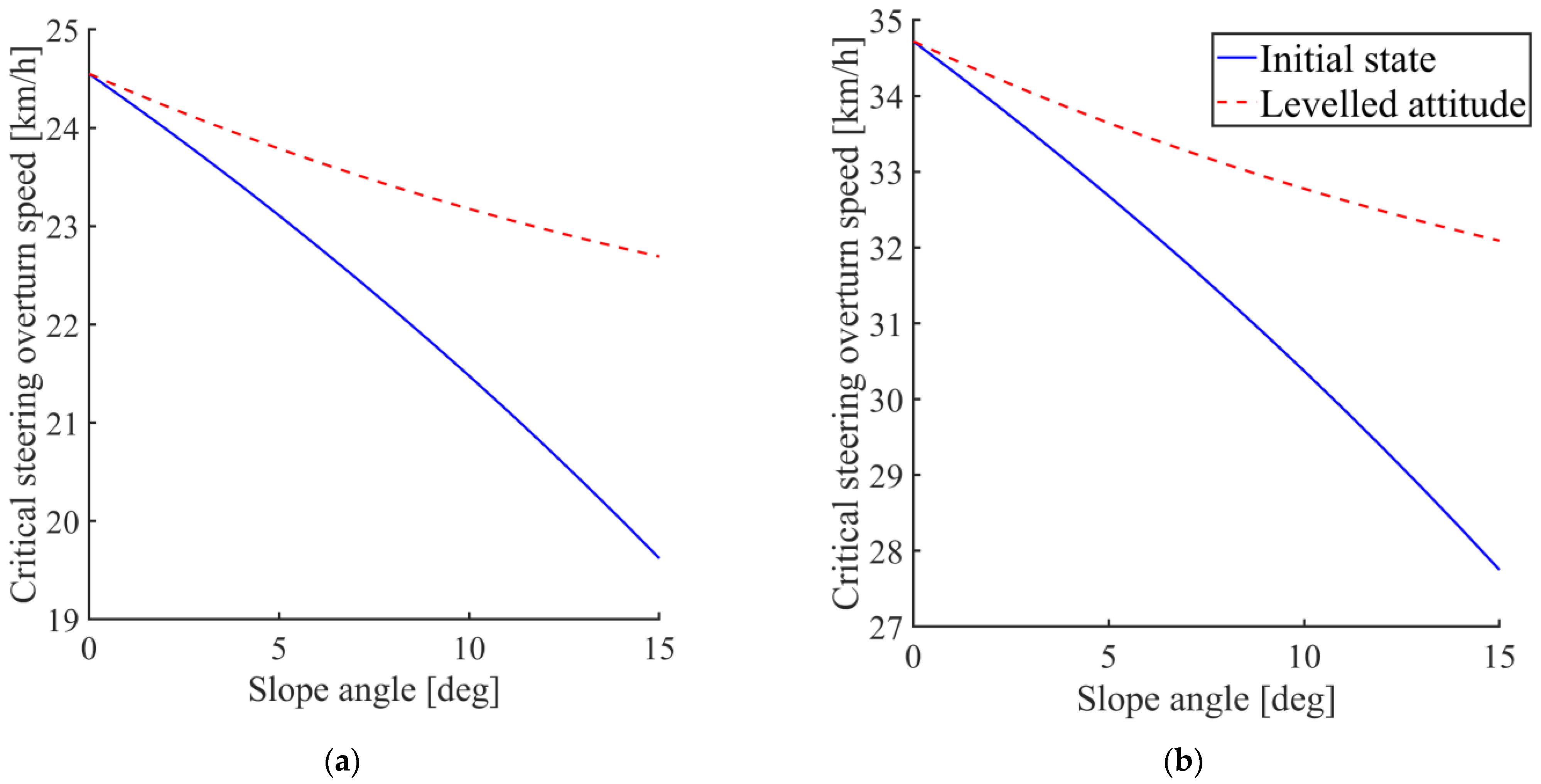
Figure 16 shows the critical steering overturning speed for both turning without attitude adjustment and turning under the level attitude mode. In general, with an increasing slope angle, the turning radius became smaller and the critical steering overturning speed decreased. In addition, the level configuration provides an effective way to enhance a tractor’s critical steering speed, which means the level configuration can enhance its lateral stability. Specifically, when the tractor traveled on a side slope with a turning radius of 6 m, the critical steering speed () in the initial state decreased from 24.55 km/h to 19.62 km/h. After leveling its attitude, the decreased from 24.55 km/h to 22.69 km/h, which is larger than that in its initial state.
Figure 16.
Lateral stability under the level attitude mode: (a) turning radius of 6 m; (b) turning radius of 12 m.
5.5. Discussion
The above results show that with the attitude adjustment method, a tractor can increase its lateral stability during steering. More specifically, its configuration can be changed by adjusting the COG heights on both the downhill and uphill sides. Moreover, an attitude adjustment mechanism can be designed to vary the unilateral ground clearance. By controlling the actuation of this mechanism, tractor attitude adjustment can be achieved to prevent tractor rollover and the resulting severe accidents.
A tractor equipped with an attitude adjustment mechanism can increase both its critical instability angle () and critical steering speed () by actively adjusting its roll angle. In general, a tractor’s lateral stability worsens during steering, decreasing as the steering radius decreases or the steering speed increases. When the steering radius and steering speed are given, the critical instability angle, , is enhanced by using the attitude adjustment method. Similarly, when the steering radius and slope angle are given, the critical steering speed, can also be increased by adjusting the rotation angle. Overall, by adjusting the COG heights on both the downhill and uphill sides, a tractor can enhance its lateral steering stability by actively adjusting its posture.
To compare the lateral stability between the initial state and level configuration, the lateral critical steering speed () in the level configuration is consistently higher than that in the initial state regardless of the slope angle. The level configuration is an effective way to enhance the tractor’s lateral stability.
This attitude adjustment method provides guidance for tractor operators. During turning, drivers should keep a low travel speed and adopt a large turning radius whenever possible. When the traveling slope increases, the COG heights on the uphill and downhill sides can be actively adjusted to change the tractor roll angle and prevent tractor rollover in practical engineering applications. Particularly during headland turning operations on sloped terrain, where the turning radius may vary, the tractor speed should be reduced as much as possible under small turning radius conditions. Moreover, before performing a headland turn, the COG positions on both sides can first be lowered to their minimum values. Subsequently, the COG height of the downhill side can be gradually raised during travel, preventing rollover and subsequent severe accidents.
When tractors travel and operate in hilly and mountainous areas, road conditions are generally stochastic. Tractors equipped with the specific attitude adjustment mechanism should be capable of simultaneously performing steering, attitude adjustment, and power transmission functions. In addition, power transmission cannot be interrupted during steering and attitude adjustment. The critical overturning slope angle and speed can also serve as evaluation indicators for actively controlling the tractor’s attitude and its associated characteristic parameters. Specifically, the adjustment angle of the attitude adjustment mechanism can be active adjusted; by actively controlling this adjustment angle, the critical slope angle and speed associated with lateral rollover of the tractor can be decreased, enabling stability motion control.
Overall, the attitude adjustment method is an effective way to enhance a tractor’s lateral stability to prevent it from overturning on hillside terrain, where lateral overturning accounts for a substantial proportion of rollover-related injuries and fatalities.
6. Conclusions
By offsetting the height difference between the uphill and downhill sides, a tractor can adjust its roll angle and configuration to enhance its stability. Based on this attitude adjustment method, we presented a mathematical model of a tractor on side slopes that represents the relationship between the configuration and its lateral stability when it steers in the front-wheel, four-wheel, and articulated body steering modes. This model takes the centrifugal force under different steering modes into account. Under the combined action of gravity and centrifugal force, tractors are more susceptible to overturning. This developed model enables the prediction of tractor overturning instability under different working conditions; e.g., varying slope and turning radius.
The results of the numerical simulations show that lateral overturning stability is greatly increased during steering when adjusting the tractor’s configuration. When the turning radius and speed are given, the critical instability slope is enhanced; when the slope and turning radius and angle are given, the critical turning speed is also increased. Even when operating on flat terrain, a tractor can actively adjust its posture to increase its critical steering speed. A level configuration is better than its initial state for lateral stability.
Author Contributions
Conceptualization, H.J., W.Z., and Y.L.; methodology, H.J. and Y.L.; software, H.J., Y.L., and X.Y.; validation, H.J. and F.G.; formal analysis, H.J. and Y.L.; investigation, H.J.; writing—original draft preparation, H.J.; writing—review and editing, H.J., Y.L., and X.Y.; visualization, Y.L. and G.X.; supervision, H.J. and F.G.; project administration, H.J.; funding acquisition, H.J., G.X., and F.G. All authors have read and agreed to the published version of the manuscript.
Funding
This research was funded by the Jilin Province Science and Technology Development Plan Project (Grant No. YDZJ202601ZYTS234) and the Scientific Research Project of Jilin Provincial Department of Education (Grant No. JJKH20261789KJ).
Institutional Review Board Statement
Not applicable.
Data Availability Statement
Data are contained within the article. Further inquiries can be directed to the corresponding author.
Acknowledgments
The authors thank the program members for their tireless contributions to the development and testing of this tractor. Without their hard work and dedication, the research performed for this paper would not be possible.
Conflicts of Interest
The authors declare no conflicts of interest.
Abbreviations
The following abbreviations are used in this manuscript:
| COG | Center of gravity |
References
- Qin, J.; Zhu, Z.; Ji, H.; Zhu, Z.; Li, Z.; Du, Y.; Song, Z.; Mao, E. Simulation of active steering control for the prevention of tractor dynamic rollover on random road surfaces. Biosyst. Eng. 2019, 185, 135–149. [Google Scholar] [CrossRef] [Scilit]
- Watanabe, M.; Sakai, K. Numerical analysis of steering instability in an agricultural tractor induced by bouncing and sliding. Biosyst. Eng. 2020, 192, 108–116. [Google Scholar] [CrossRef] [Scilit]
- Abubakar, M.S.a.; Ahmad, D.; Akande, F.B. A review of farm tractor overturning accidents and safety. Pertanika J. Sci. Technol. 2010, 18, 377–385. [Google Scholar]
- Li, Z.; Mitsuoka, M.; Inoue, E.; Okayasu, T.; Hirai, Y. Development of stability indicators for dynamic Phase I overturn of conventional farm tractors with front axle pivot. Biosyst. Eng. 2015, 134, 55–67. [Google Scholar] [CrossRef] [Scilit]
- He, Z.; Song, Z.; Wang, L.; Zhou, X.; Gao, J.; Wang, K.; Yang, M.; Li, Z. Fasting the stabilization response for prevention of tractor rollover using active steering: Controller parameter optimization and real-vehicle dynamic tests. Comput. Electron. Agric. 2023, 204, 107525. [Google Scholar] [CrossRef] [Scilit]
- Latorre-Biel, J.-I.; Ballesteros, T.; Arana, I.; Alfaro, J.R. Development of an inexpensive rollover energy dissipation device to improve safety provided by ROPS. Biosyst. Eng. 2019, 185, 88–102. [Google Scholar] [CrossRef] [Scilit]
- Ayers, P.; Khorsandi, F.; Wang, X.; Araujo, G. ROPS designs to protect operators during agricultural tractor rollovers. J. Terramechanics 2018, 75, 49–55. [Google Scholar] [CrossRef] [Scilit] [PubMed]
- Ballesteros, T.; Arana, J.I.; de Ezcurdia, A.P.; Alfaro, J.R. Development and validation of automatically deployable ROPS based on airbag inflator technology. Biosyst. Eng. 2015, 130, 92–105. [Google Scholar] [CrossRef] [Scilit]
- Franceschetti, B.; Lenain, R.; Rondelli, V. Comparison between a rollover tractor dynamic model and actual lateral tests. Biosyst. Eng. 2014, 127, 79–91. [Google Scholar] [CrossRef] [Scilit]
- Ahmadi, I. Dynamics of tractor lateral overturn on slopes under the influence of position disturbances (model development). J. Terramechanics 2011, 48, 339–346. [Google Scholar] [CrossRef] [Scilit]
- Franceschetti, B.; Rondelli, V.; Capacci, E. Lateral Stability Performance of Articulated Narrow-Track Tractors. Agronomy 2021, 11, 2512. [Google Scholar] [CrossRef] [Scilit]
- Capacci, E.; Franceschetti, B.; Guzzomi, A.; Rondelli, V. Energy Absorption in Actual Tractor Rollovers with Different Tire Configurations. Int. J. Environ. Res. Public Health 2021, 18, 6517. [Google Scholar] [CrossRef] [Scilit] [PubMed]
- Jang, M.-K.; Hwang, S.-J.; Kim, J.-H.; Nam, J.-S. Overturning and rollover characteristics of a tractor through dynamic simulations: Effect of slope angle and obstacles on a hard surface. Biosyst. Eng. 2022, 219, 11–24. [Google Scholar] [CrossRef] [Scilit]
- Li, Z.; Mitsuoka, M.; Inoue, E.; Okayasu, T.; Hirai, Y.; Zhu, Z. Parameter sensitivity for tractor lateral stability against Phase I overturn on random road surfaces. Biosyst. Eng. 2016, 150, 10–23. [Google Scholar] [CrossRef] [Scilit]
- Kayacan, E.; Kayacan, E.; Ramon, H.; Saeys, W. Towards agrobots: Identification of the yaw dynamics and trajectory tracking of an autonomous tractor. Comput. Electron. Agric. 2015, 115, 78–87. [Google Scholar] [CrossRef] [Scilit]
- Chen, F.; Ding, J.; Luo, Z.; Zheng, E.; Lu, Y.; Shi, Y.; Zhang, Y.; Wang, X. A novel robust model predictive controller for improving the steering stability of electric drive mobile platform considering the effect of both yaw motion and rototiller lifting. Comput. Electron. Agric. 2025, 230, 109846. [Google Scholar] [CrossRef] [Scilit]
- Watanabe, M.; Kazama, K.; Sakai, K. Numerical analysis on tractor axle suspension for steering instability induced by bump disturbances. Biosyst. Eng. 2024, 242, 100–106. [Google Scholar] [CrossRef] [Scilit]
- Song, Z.; Wang, L.; Liu, Y.; Wang, K.; He, Z.; Zhu, Z.; Qin, J.; Li, Z. Actively steering a wheeled tractor against potential rollover using a sliding-mode control algorithm: Scaled physical test. Biosyst. Eng. 2022, 213, 13–29. [Google Scholar] [CrossRef] [Scilit]
- Watanabe, M.; Sakai, K. Impact dynamics model for a nonlinear bouncing tractor during inclined passage. Biosyst. Eng. 2019, 182, 84–94. [Google Scholar] [CrossRef] [Scilit]
- Song, Z.; Luo, Z.; Wei, G.; Shang, J. A portable six-wheeled mobile robot with reconfigurable body and self-adaptable obstacle-climbing mechanisms. J. Mech. Robot. 2022, 14, 51010. [Google Scholar] [CrossRef] [Scilit]
- Kim, D.; Hong, H.; Kim, H.S.; Kim, J. Optimal design and kinetic analysis of a stair-climbing mobile robot with rocker-bogie mechanism. Mech. Mach. Theory 2012, 50, 90–108. [Google Scholar] [CrossRef] [Scilit]
- Aoki, T.; Murayama, Y.; Hirose, S. Development of a transformable three-wheeled lunar rover: Tri-Star IV. J. Field Robot. 2014, 31, 206–223. [Google Scholar] [CrossRef] [Scilit]
- Cordes, F.; Dettmann, A.; Kirchner, F. Locomotion modes for a hybrid wheeled-leg planetary rover. In Proceedings of the 2011 IEEE International Conference on Robotics and Biomimetics, Karon Beach, Thailand, 7–11 December 2011; pp. 2586–2592. [Google Scholar]
- Reid, W.; Pérez-Grau, F.J.; Göktoğan, A.H.; Sukkarieh, S. Actively articulated suspension for a wheel-on-leg rover operating on a martian analog surface. In Proceedings of the 2016 IEEE International Conference on Robotics and Automation (ICRA), Stockholm, Sweden, 16–21 May 2016; pp. 5596–5602. [Google Scholar]
- Wettergreen, D.; Moreland, S.; Skonieczny, K.; Jonak, D.; Kohanbash, D.; Teza, J. Design and field experimentation of a prototype lunar prospector. Int. J. Robot. Res. 2010, 29, 1550–1564. [Google Scholar] [CrossRef] [Scilit]
- Jiang, H.; Xu, G.; Zeng, W.; Gao, F. Design and kinematic modeling of a passively-actively transformable mobile robot. Mech. Mach. Theory 2019, 142, 103591. [Google Scholar] [CrossRef] [Scilit]
- Jiang, H.; Xu, G.; Zeng, W.; Gao, F.; Chong, K. Lateral stability of a mobile robot utilizing an active adjustable suspension. Appl. Sci. 2019, 9, 4410. [Google Scholar] [CrossRef] [Scilit]
- Mashadi, B.; Nasrolahi, H. Automatic control of a modified tractor to work on steep side slopes. J. Terramechanics 2009, 46, 299–311. [Google Scholar] [CrossRef] [Scilit]
- Aziz, R.M.S.; Samieifar, A.; Mehrabani, M.H.; Khaqanifar, M. Design and manufacture of an appropriate suspension mechanism for the wheels of the tractor for moving on transveral slopes. Int. J. Agric. Crop Sci. 2014, 7, 1406–1416. [Google Scholar]
- Gao, Q.; Gao, F.; Tian, L.; Li, L.; Ding, N.; Xu, G.; Jiang, D. Design and development of a variable ground clearance, variable wheel track self-leveling hillside vehicle power chassis (V2-HVPC). J. Terramechanics 2014, 56, 77–90. [Google Scholar] [CrossRef] [Scilit]
- Wang, Y.; Yang, F.; Pan, G.; Liu, H.; Liu, Z.; Zhang, J. Design and testing of a small remote-control hillside tractor. Trans. ASABE 2014, 57, 363–370. [Google Scholar] [CrossRef] [Scilit]
- Peng, H.; Ma, W.; Zhao, E.; Lu, X.; Feng, X. Design and physical model experiment of body leveling system for roller tractor in hilly and mountainous region. Trans. Chin. Soc. Agric. Eng. 2018, 34, 36–44. [Google Scholar]
- Zhu, Y.; Kan, J. Prediction of the lateral stability of a forestry chassis with an articulated body and fitted with luffing wheel-legs. Biosyst. Eng. 2022, 224, 143–160. [Google Scholar] [CrossRef] [Scilit]
- Jiang, H.; Xu, G.; Zeng, W.; Gao, F.; Tang, X. Design and Lateral Stability Analysis of an Attitude Adjustment Tractor for Moving on Side Slopes. Appl. Sci. 2024, 14, 2220. [Google Scholar] [CrossRef] [Scilit]
- Ben Hazem, Z.; Fotuhi, M.J.; Bingul, Z. A Comparative Study of the Joint Neuro-Fuzzy Friction Models for a Triple Link Rotary Inverted Pendulum. IEEE Access 2020, 8, 49066–49078. [Google Scholar] [CrossRef] [Scilit]

Disclaimer/Publisher’s Note: The statements, opinions and data contained in all publications are solely those of the individual author(s) and contributor(s) and not of MDPI and/or the editor(s). MDPI and/or the editor(s) disclaim responsibility for any injury to people or property resulting from any ideas, methods, instructions or products referred to in the content. |
© 2026 by the authors. Licensee MDPI, Basel, Switzerland. This article is an open access article distributed under the terms and conditions of the Creative Commons Attribution (CC BY) license.