


Abstract
The shipping sector is responsible for a considerable share of global CO2 emissions and is under pressure to reduce emissions and adopt carbon-neutral fuels. Among the proposed alternatives, methanol produced from green hydrogen and biogenic CO2 represents a promising option. However, the feasibility of its production is significantly influenced by the composition and variability of the bio-CO2 feedstock, which can negatively impact the complete value chain. To address these challenges, sampling campaigns were carried out at actual bio-CO2-emitting sites, namely biogas and biomass combustion facilities, to characterize the impurity profiles and determine the appropriate conditioning requirements. A novel membrane gas absorption system with a Diethanolamine solution was deployed directly in the field to capture, as well as purify to a certain extent, the CO2 stream. The system demonstrated high efficiency in removing most impurities, achieving high CO2 capture rates and impurity reduction close to 90%. However, residual chlorine species were detected in the CO2 streams from biogas plants, suggesting the need for additional conditioning to meet the purity specifications required for methanol synthesis. Given that the feedstock composition and upstream process conditions could significantly affect the final output and present considerable variations, the implementation of additional cleaning measures is recommended before synthesis.
1. Introduction
The maritime sector accounts for approximately 3% of global greenhouse gas emissions, primarily due to its reliance on fossil-based fuels, such as Marine Diesel Oil and Heavy Fuel Oil. According to the IMO, CO2-equivalent emissions increased from 794 Mt in 2012 to over 1076 Mt in 2018 and are projected to exceed 1 Gt annually by 2050 without mitigation measures [1]. Given the projected emissions growth, maritime decarbonization has become an urgent global priority with different solutions being investigated, such as adoption of alternative fuels, on-board carbon capture, energy-efficiency and operational improvements [2]. Among the various options, the adoption of alternative marine fuels and particularly methanol stands out due to its combustion properties, compatibility with existing infrastructure, and liquid state under ambient conditions, which facilitates storage and handling procedures [3]. MeOH production pathways vary, with increasing focus on e-methanol, which can be synthesized from different CO2 sources and green hydrogen [4,5]. In most practical configurations, the required CO2 is captured from industrial point sources where relatively concentrated streams are available, rather than directly from dilute emissions sources. The composition and purity of the captured CO2 stream are critical parameters that influence downstream synthesis performance and overall process feasibility. While the technology is commercially viable, its scalability remains constrained by issues such as increased costs and feedstock availability [6].
The origin of both the hydrogen and carbon feedstock for the synthesis will affect, to a large extent, the environmental and economic performance of the methanol synthesis process [7]. Bio-CO2 refers to CO2 emitted from industrial facilities that use biomass in the upstream production processes. Key sectors of biogenic CO2 include biomass-based facilities, such as biogas/biomethane plants, biomass combustion units, pulp and paper industries, bioethanol facilities, and food and beverage plants [8]. The use of biogenic, rather than fossil-derived CO2, is linked to a neutral carbon cycle and does therefore not induce additional stress to the atmospheric carbon cycle. Biomass feedstocks can be utilized upstream through different conversion pathways, resulting in downstream CO2 streams with heterogeneous compositions and impurity profiles that may also exhibit seasonal variability [9]. The integration of such biogenic CO2 streams into the methanol synthesis value chain poses several technical challenges. The wide spatial distribution of facilities could complicate logistics, whereas the significant variation in plant sizes poses an additional challenge for achieving economies of scale, particularly in smaller facilities such as biogas/biomethane plants with low specific emissions. Furthermore, the diversity of upstream processes and the variability in feedstock composition contribute to the presence of trace impurities, which can affect CO2 transport and downstream catalytic performance. In addition, fluctuations in CO2 purity and operating conditions (e.g., pressure, moisture content, temperature) further complicate its direct utilization, necessitating dedicated gas cleaning measures. A thorough characterization of each CO2 source is therefore essential to ensure stable and long-term operation, irrespective of seasonal fluctuations [10].
CO2 captured from different facilities may contain a range of trace contaminants. Their presence and concentrations are influenced by several factors, including the type of feedstock, upstream process conditions, the employed capture technology and downstream purification steps. Common contaminants include oxygen, nitrogen, sulfur compounds (SOx, H2S), halogens, ammonia, siloxanes, heavy metals and particulates. While not all components pose equal risk, some can severely affect the overall value chain, where even trace amounts can impact catalyst performance, transportation efficiency and system integrity [11]. Similar observations have already been reported by the authors in previous studies [4,5], where investigations into the utilization of steelworks off-gases for methanol and methane synthesis emphasized the need for gas cleaning to prevent catalyst poisoning.
For this purpose, impurity-related risks could span across three key stages of the bio-CO2-to-methanol value chain:
- (i)
- Pre-capture, where acid gases such as SOx and NO2 irreversibly degrade amine-based solvents, forming heat-stable salts and increasing operational costs. Physical impurities like fly ash can also cause fouling and loss of absorption capacity [12];
- (ii)
- CO2 transportation, where impurities affect thermophysical properties and corrosion potential. For pipeline and liquid-phase transport (via ship/truck), adherence to ISO standards is essential to ensure system reliability and safety [13,14,15].
- (iii)
- Methanol synthesis, where the presence of sulphur, chlorine, and oxygen can deactivate the catalyst via sintering, poisoning or structural degradation. Solid particles and trace metals also contribute to performance loss.
To enable high-purity CO2 recovery on-site, the modular Membrane-based Gas Absorption (MGA) process could offer a promising solution, even for low CO2-emitting sites. This system combines the advantages of selective chemical absorption with membrane technology, allowing for efficient and scalable CO2 separation. The MGA process is particularly attractive for decentralized applications like biogas plants due to its modularity, low energy demand, and operational flexibility [16]. Apart from capturing the emitted CO2, it could also purify to a certain extent the gaseous stream, thus lowering the cleaning requirements before MeOH synthesis.
Although MGA has been widely studied for CO2 capture, most existing work relies on model gas mixtures and emphasizes absorption efficiency rather than CO2 purification quality under realistic conditions. Limited studies have evaluated MGA performance with real biogenic streams characterized by humidity, trace contaminants, and fluctuating compositions, nor have they explicitly assessed compliance with downstream methanol synthesis specifications. In this work, MGA is validated under representative biogas and combustion exhaust conditions and directly linked to impurity management and fuel-synthesis requirements, thereby providing a deployment-oriented assessment of the technology for decentralized bio-CO2 valorization.
Despite the growing interest in biogenic CO2, quantitative field data linking source-specific impurity profiles to catalyst tolerance limits and transport specifications remain limited. In particular, the lack of integrated source-specific measurements across capture, transportation, and synthesis-relevant stages limits evidence-based design of gas cleaning strategies. This work addresses this gap by providing a systematic, multi-stage characterization of real biogenic-CO2 streams and directly translating measured impurity levels to conditioning requirements for methanol synthesis. To achieve this, targeted sampling campaigns were conducted at prevailing bio-CO2-emitting upstream processes (anaerobic digestion and combustion-related) to characterize the emission composition and identify trace contaminants with potential catalytic or operational impacts. The MGA process was applied to capture and enhance CO2 quality. The CO2 composition is evaluated at multiple stages of the process, prior to capture, post-capture and pre-synthesis, benchmarking different analytical methods for trace-level quantification and thereby providing a comprehensive basis for selecting conditioning technologies.
The novelty of this work lies in the direct field deployment of a modular MGA system at diverse industrial bio-CO2 sites, as well as in the analysis of the gaseous stream along the different steps in the chain. Unlike laboratory studies using synthetic gases, this research provides a comprehensive value-chain analysis, tracking impurities from raw feedstock to transport-ready CO2. It further establishes MGA as a dual-purpose technology for both high-rate capture and effective gas purification. This work is organized as follows: Section 2 provides the experimental materials and methods, the sampling and analysis procedures, as well as the deployed capture and regeneration unit. Section 3 presents and discusses the obtained results, and Section 4 summarizes the main conclusions of the study and hints for future research.
2. Materials and Methods
A standardized, multi-point sampling and analysis protocol was applied across the three investigated facilities. Two representative biogenic CO2 source types were examined: anaerobic digestion units and biomass combustion. For each case, gas sampling was performed at the outlet of the primary process, upstream of any CO2 capture or additional gas cleaning, in order to determine the raw stream composition. The same gas stream was subsequently routed to an on-site membrane gas absorption (MGA) unit operated with an amine-based solvent for capture. After solvent saturation, liquid samples were collected for the quantification of transferred trace impurities. A regeneration step was then carried out to release the captured CO2, and the recovered gas was analyzed to determine its final composition. Gas- and liquid-phase analyses at these three defined stages enabled systematic tracking of impurity behavior throughout the capture and purification sequence (Figure 1).
Figure 1.
Sequential multi-stage sampling framework. The protocol tracks impurities through raw streams, saturated 2M DEA solvent, recovered CO2.
2.1. Description of Biogenic CO2 Sources
Three industrial-scale biogenic CO2 sources in Northern Greece were selected for the sampling campaigns, representing anaerobic digestion (Biogas Plants No.1 and No.2) and biomass combustion (Biomass combustion plant). These facilities provide diverse impurity profiles reflecting typical agricultural and woody biomass feedstocks. All measurements were conducted under steady-state operational conditions at nominal capacity to ensure sample integrity. Sampling points were strategically located downstream of existing gas cleaning systems to characterize the actual emitted streams intended for CO2 capture. Technical specifications for each facility are summarized in Table 1.
Table 1.
Technical characteristics of the investigated bio-CO2 facilities. Measurements were conducted under steady-state conditions at nominal capacity. Gas composition is expressed in vol%.
2.2. Bio-CO2 Sampling and Analysis Procedures
The sampling strategy was designed to assess variations in CO2 content, with two defined points: the direct analysis of the raw stream and the analysis of the MGA-treated stream. Measurements were performed in series for biogas plants and simultaneously under isokinetic conditions for biomass combustion plants. Due to the continuous and stable flue gas velocities in combustion facilities, isokinetic sampling was applied to ensure accurate and representative sampling of both particulate matter and gaseous compounds. In contrast, biogas plants operate under batch or semi-batch regimes, as anaerobic processes typically exhibit retention times of ~60 days. This distinction between continuous and batch operation directly affects both the selection of sampling methodology and the interpretation of analytic results, emphasizing the need to align protocols with facility-specific process dynamics.
2.2.1. Sampling Procedure in Biogas Facilities
During the sampling campaign, two in-series measurements were conducted: one focusing on the bio-CO2 stream analysis and the other on evaluating the membrane-based system application, making sure that the same stream is both analyzed and utilized in the capture unit. The schematic (Figure 2) illustrates a standard biogas process from biomass pretreatment and anaerobic digestion through gas conditioning, including gas holding (buffering) and desulfurization. The sampling point is located downstream of the desulfurization unit and upstream of the CHP unit, allowing the assessment of trace impurities in treated biogas prior to final utilization. The pressure and temperature conditions at the sampling points for the two experiments were 20 bar and 80 °C for the first and 23 bar and 115 °C for the second biogas plant.
Figure 2.
Schematic of the sampling and CO2 recovery points at the anaerobic digestion facilities. Points are located downstream of the desulfurization unit and upstream of the CHP unit.
The raw gas samples were collected using Tedlar® gas sampling bags (Sigma-Aldrich, St. Louis, MO, USA) and transported for off-site analytical characterization. Particular emphasis was given to sulphur and siloxane compounds, with siloxanes being common impurities contained at significant concentrations in biogas streams, leading to potential fouling and failures in downstream equipment [17,18,19]. Subsequently, the MGA unit was connected for a 2 h operation, where, after solvent saturation, the liquid samples were collected and stored to perform further analysis, both in the amine solvent as well as in the recovered bio-CO2 to identify the maximum concentration of impurities in the methanol synthesis reactor inlet. More information on the saturated amine analyses is included in Section 3.2 and in the Supplementary Material.
2.2.2. Sampling Procedure in Biomass Combustion Plant
In this case, a comprehensive analysis of the biomass feedstock was conducted to better understand its composition and potential impact. The detailed characterization focuses on elemental and inorganic constituents relevant to downstream CO2 processing. In addition, representative gas samples were collected from the combustion unit following a structured sampling methodology to enable reliable analytical evaluation. Water-tube boilers operate at high temperatures under well-controlled combustion conditions, facilitating efficient ash separation. Biomass ash is typically divided into bottom ash (composed of heavier, less volatile elements) and fly ash, which contains more volatile constituents suspended in the flue gas phase [20]. The volatility of elements enables a preliminary prediction of the flue gas impurity profile, guiding the design of targeted sampling campaigns. These predictions are based on feedstock composition and the impurity tolerance thresholds defined by methanol catalyst specifications [12]. On the day of the sampling, the feedstock consisted of 99% wood and 1% pellet. Biomass feedstock samples were collected and prepared according to ISO 14780-Solid Biofuels-Sample Preparation [21] and quantification of trace elements was conducted using ICP-MS/XRF equipment (7850 ICP-MS, Agilent Technologies Inc., Santa Clara, CA, USA). The elemental composition of biomass feedstock, including carbon, hydrogen, and nitrogen contents, was determined according to the EN15404:2011 standard, which describes instrumental methods for the quantification of total carbon, hydrogen and nitrogen in solid fuels [22]. The focus was on the elemental structure and on key inorganic elements such as alkali metals, chlorine and ash-forming compounds, which are known to influence combustion behavior and the formation of gas-phase impurities [23].
In this sampling campaign, measurements were conducted under isokinetic conditions to ensure representative sampling of the gas stream. Throughout the sampling campaign, one of the two boilers was operational, contributing a power of 12 MW, very close to its nominal value. Under these conditions, steady-state operation was maintained, providing high integrity of the sample collection for impurity identification. The weather conditions proved harsh, with temperatures ranging between approximately 1 and 5 °C. This resulted in increased heat demands in the region and led to the boiler operating at near-nominal values at 600–650 °C. Two sampling points were installed downstream of the filter (Figure 3), where the flow exhibited laminar characteristics. The resulting flue gas exited the facility at 1 bar, 130 °C and with a flow rate of 9.7 L/min (at the pitot entrance). One sample line was used to perform the MGA process, utilizing a similar system as in the biogas campaigns, while the other one was designated for the analysis of the flue gas stream.
Figure 3.
Layout of the sampling and CO2 recovery configuration at the biomass combustion plant. Points were installed downstream of the bag filters in a laminar flow zone.
To ensure isokinetic sampling, a probe, equipped with a Pitot tube, was positioned at the gas collection point. A filtration system was implemented to separate particulate matter from the flue gases, followed by a series of impingers containing specific absorption solutions. The sampling line was heated up to the entry point of the gas stream into the impinger system to prevent condensation. The number of impingers and the type of reactant solution varied depending on the specific impurity being analyzed (Table 2). In all cases, the final stage of the impinger array consisted of a column filled with silica gel for the removal of residual moisture, preventing potential interference with the analytical process (Figure 4).
Table 2.
Impinger solution parameters for flue gas impurity analysis in biomass combustion campaign. Sampling was performed using specific absorption solutions with a duration of 45–60 min and solution quantities in mL.
Figure 4.
Experimental setup for the analysis of flue gases (a) Setup for the identification of halogens (HCl, HF) and mercury (Hg). Impingers solutions: 100 mL chloride-free water (HCl), 100 mL NaOH 0.1 M (HF), Greenburg Smith impingers 100 mL 4% K2Cr2O7 + 20% HNO3. Tpr = Tf = 160 °C for halogens, Tpr = Tf > Tgas + 20 °C. (b) Set up for the identification of heavy metals.
The sampling system operated through a pump, controlling the flow rate. At the same time, it measured the pressure drop in the Pitot tube in order to determine the gas velocity and verify the isokinetic conditions. As discussed previously, the impingers contained specific sorbent solutions chosen to selectively capture the target gas species. Inside each impinger, the selected gas reacted with the corresponding solution, while the unreacted gases were passed through and exited the system. To improve the capture efficiency, multiple impingers were used in each measurement, resulting in a higher overall capture rate and minimizing potential losses. After absorption, the resulting liquid mixture containing the dissolved reaction products was collected and subjected to further analytical procedures to determine the concentration of the collected species. The concentrations of O2, CO2, SO2, CO and NOx in the flue gas stream were determined on a dry gas basis, using a portable gas analyzer (ENVEA MIR 9000P, Poissy, France). The analysis of impurities in the carbon dioxide stream aims to identify and quantify the presence of halogens and heavy metals. The campaign duration exceeded 2 h, allowing saturation of the solvent under steady-state operation. Following the completion of absorption, the CO2-rich solvent samples were collected and transported to the laboratory for off-site analysis. Consistent with prior procedures, the selection of analytical methods was based on standardized protocols. As for the targeted analysis of saturated amine, the selected analytical methods are the same as those used in biogas sampling campaigns and are described in detail in Section 3.2.
2.3. CO2 Capture Apparatus and Procedures
To capture the bio-CO2 from each stream, an innovative approach was adopted, namely membrane gas absorption (MGA). It is a hybrid technology for CO2 capture that combines the principles of chemical absorption with membrane-based separation. In MGA systems, hollow fiber membrane contactors act as a physical barrier between the gas and liquid phases, allowing efficient CO2 transfer without phase mixing [16,24]. Using hydrophobic hollow fiber membranes ensures that the pores remain gas-filled, while maintaining the liquid pressure slightly above the gas pressure, creating a stable interface that enables efficient CO2 absorption with minimal mass transfer resistance (Figure 5).
Figure 5.
Mechanism of the membrane gas absorption (MGA) process. The diagram illustrates the gas–liquid interface within the hydrophobic hollow fiber pores, where selective chemical absorption occurs [24].
Compared to conventional packed columns, MGA offer several advantages: high and constant specific contact area (1500–7000 m2/m3 vs. 100–800 m2/m3), flexibility to operate under wide range of gas–liquid ratios without flooding or unloading issues, and the ability to handle diverse CO2 concentrations, from industrial flue gases (5–20%) to raw biogas (45–50%). This technology system is compact, modular and easily scalable, enabling predictable performance with lower maintenance costs. The MGA unit consists of two main sections that interact within the membrane module: the liquid phase and the gas phase sections. Both sections are fully equipped with dedicated instrumentation for independent control, operation and analysis. The gas phase section involves the introduction of a CO2-rich stream, which is either flue gas or biogas, directed from the plant through a series of valves, pressure and temperature indicators into the lumen side of membranes where the absorption process takes place. Its volumetric flow rate is controlled and monitored using a dedicated gas pump and flow meter. The gas outlet stream is dried through a HEPA and a drierite filter to remove humidity and any particulate matter before entering the gas analyzer and then ventilated into the atmosphere. In the liquid section, an aqueous Diethanolamine (DEA99%, Chem-Lab NV, Zedelgem, Belgium; now AnalytiChem Belgium NV) solution at 2M, prepared in the laboratory, is pumped from the feed tank to the shell side of the membranes in counter-current flow configuration. The CO2-rich solvent is then recirculated back into the feed tank. A detailed process flow diagram of the capture apparatus is shown in Figure 6.
Figure 6.
Process flow diagram of the modular MGA capture and analysis unit. The system features the 3M Liqui-CelTM contactor, Ismatec BVP-Z pumps and the Cubic-Ruiyi Gasboard-3200 analyzer.
The membrane module used was a 2.5 × 8 Liqui-CelTM 3M EXF membrane contactor (Charlotte, NC, USA, Liqui-CelTM). Detailed technical characteristics of the module are provided in Table 3. Prior to each experimental campaign, the membrane—though not new—was conditioned by overnight drying under a nitrogen (N2) atmosphere. The pumps used to deliver the gaseous and liquid streams to the membrane were a Rietschie Thomas 107 series (Rietschle Thomas GmBh, PubChem, Germany) and an Ismatec BVP-Z (Ismatec ISM446B-230V (B-MOUNT) BVP-Z Analog Gear Pump Drive, Glattbrugg, Switzerland), respectively. The gas analyzer was the Cubic-Ruiyi Gasboard-3200 Online Infrared Biogas Analyzer (Hubei Cubic-Ruiyi Instruments Co., Ltd., Wuhan, China, Gasboard-3100 Serial Syngas Analyzer); its detailed technical characteristics can be seen in the Supplementary Material.
Table 3.
Technical specifications of the 3M Liqui-CelTM 2.5 × 8 EXF membrane contactor. Parameters include effective membrane area (cm2), fiber dimensions (cm), pore size (μm) and fiber material used in the MGA capture campaigns [25,26].
The experimental procedure involved a systematic sequence of steps. Initially, the liquid solvent was prepared and loaded into the system. A thorough analysis of the feed gas streams’ composition and total flow measurement was performed. Both the gas and liquid streams were fed into the membrane module. Throughout the process, the liquid phase pressure was carefully monitored and regulated to be slightly higher than the gas phase pressure, preventing any unintended dispersion while minimizing long-term wetting effects. Real-time analysis of the gas effluent’s composition was performed using a gas analyzer. Finally, the effect of various process parameters, such as gas and liquid flow rates and the gas-to-liquid (G/L) ratio, on the overall performance was continuously monitored. The operating conditions recorded during the sampling and system performance evaluation are summarized in Table 4. These parameters reflect the pressure, temperature, and flow rate of both gas and solvent at the MGA feed, providing essential context for understanding system behavior under real operational conditions.
Table 4.
Experimental operating conditions during the 2 h MGA sampling campaigns. Specifications include pressure (bar), temperature (°C) and gas/liquid flow rates (L/min) for the two biogas plants and the biomass combustion facility.
The campaign was considered complete upon full saturation of the amine solution. Subsequently, a comprehensive screening was performed on the saturated amine-CO2 solution to quantify trace elements and potential impurities absorbed within the mixture. More specifically, density was measured at 25 °C using a Digital Density Meter (ASTM D42052-18a) (DMA 35, Anton Paar GmBh, Graz, Austria) to identify the increase that occurred since capturing. To further characterize these interactions, Fourier Transform Infrared Spectroscopy (FT-IR) was performed on both saturated and unsaturated solvent samples using a JASCO FT/IR-6700 spectrometer (Jasco Corporation, Tokyo, Japan). The spectral analysis enabled the identification of vibrational modes corresponding to carbamate and carbonate functional groups formed during CO2 absorption, as well as potential peaks attributable to impurities present in the CO2 stream. The FT-IR spectra were processed using the instrument software, applying water signal correction and spectral smoothing to reduce noise, while no baseline correction was applied. The analysis was intended primarily for qualitative comparison of solvent loading and regeneration states rather than quantitative determination of absorbed species; therefore, peak integration was not performed. This analysis facilitated the estimation of the maximum concentration of impurities potentially present in the recovered CO2 stream, assuming full recovery efficiency (more information in the Supplementary Material).
2.4. Gas Stripping Process-Solvent Regeneration
A gas stripping unit was employed to generate the solvent batches up to 0.33 L by controlled heating, which facilitated both CO2 recovery and solvent regeneration. The apparatus consisted of a heating mantle, boiling flask, and vertical condenser, with batches corresponding to 50–66% of flask volume to ensure efficient heat transfer and controlled evaporation. Thermal desorption was carried out at 95 °C for 1 h. The released gas was withdrawn using a CO2Meter diaphragm pump (model PMP-0012, nominal lifetime 10,000 h, maximum flow rate 0.8 L min−1, Ormond Beach, FL, USA). No carrier gas was employed, and the stripping relied exclusively on thermal desorption of the dissolved CO2. Process temperature was regulated using an integrated control of the heating mantle, whereas gas samples were collected through a three-way valve at the condenser outlet, with leak-tight operation secured by clamps. The heating mantle (ISOLAB Laborgeräte GmBh, with magnetic stirrer, Eschau, Germany) provided precise control up to 450 °C and variable stirring speeds, while tap water was continuously supplied to the condenser as a cooling medium for efficient condensation of solvent vapors.
The experimental procedure involved preparing the gas stripping apparatus, transferring a measured volume of solvent into the boiling flask, and verifying gas-tightness through leak testing. The heating mantle was then activated, with temperature and pressure continuously monitored, while desorbed gases and regenerated solvent samples were collected for analysis. In total, three lab-scale desorption experiments were conducted using saturated solvents from the biogas and biomass combustion facilities. The desorbed CO2 stream was collected during each desorption experiment to determine the composition of the released gases, with particular emphasis on CO2, hydrocarbons and trace impurities. Analysis was performed using an Agilent 7890B Gas Chromatograph (GC) (Agilent Technologies Inc., Santa Clara, CA, USA) configured with four valves, two thermal conductivity detectors (TCD) and one flame ionization detector (FID), and equipped with HayeSep, Molecular Sieves, DB-1 and HP-AL columns. The FID channel was used for C1–C5 hydrocarbon analysis, while the first TCD channel (He reference gas) was used for permanent gases (CO2, CO, O2, N2 and H2S) and the second TCD channel (N2 reference gas) for hydrogen detection. The GC system was calibrated using certified calibration gas mixtures containing the target components. The method allowed quantification of permanent gases (CO2, CO, N2, O2, H2), light hydrocarbons (C1–C5) and H2S, with detection limits in the range of 0.01 vol% for hydrocarbons,-0.1 vol% for permanent gases, and 0.05 vol% for H2S mol%.
2.5. Analytic Methods and Equipment
Given that the sampling campaign involved gas–liquid and gas–gas phase measurements, standardized analytical methods were applied throughout the analysis.
Within this framework, analytical methods were applied for the characterization of the flue gas stream. Acid gases (HCl, HF and SO2) were quantified by ion chromatography (ISO15713, EN14791 and EN ISO10304) [27,28,29]. Total mercury (Hg) was determined using fluorescence spectrometry (EN ISO17852, EN13211 and ISO12846) [30,31,32]. Heavy metals were quantified by inductively coupled plasma atomic emission spectrometry (ICP-AES) based on EPA Method 200.7.
Analytic methods were also applied to quantify selected inorganic impurities in the amine solutions collected during the sampling campaigns. Specifically, halides and sulphate were quantified by ion chromatography following SMEWW 4500. In addition, sulphides were determined spectrometrically in accordance with ISO10530:2002 [33]. Arsenic was also performed following ASTM D2972-03, employing photometric and atomic absorption techniques [34]. Mercury was analyzed according to ASTM D3223:2000, involving atomic absorption spectroscopy (CVAAS), while antimony was quantified by flame atomic spectroscopy (FAAS), in accordance with ISO15586:2003 [35,36].
As part of the analytical quality assurance procedure, the blank method was systematically applied during the measurements. Blank samples were analyzed under the same experimental and instrumental conditions as the actual samples, in order to account for potential background signals, reagent impurities, or contamination originating from the sampling and analytical setup. The blank values were considered during data evaluation to ensure that the reported concentrations reflect only the contribution of the investigated CO2 streams and absorbed species.
Due to the industrial-scale nature of the facilities and operational constraints, full experimental replication was not feasible for all sampling stages. Measurements were conducted under steady-state operating conditions during dedicated sampling campaigns. Reported uncertainties reflect analytical measurement uncertainty rather than experimental repeatability.
3. Results
To systematically profile bio-CO2 stream contaminants throughout the value chain and evaluate the potential presence of certain impurities in the final CO2 stream, analyses were conducted at the (Figure 1): (i) raw streams prior to the capture system, (ii) saturated amine solution, and (iii) recovered bio-CO2 after the MGA unit. This multi-step approach enabled the construction of a complete picture of the possible impurities contained in the CO2 stream, including their persistence through the various stages of processing. For each of the conducted sampling campaigns, the results are presented in this section and evaluated against established tolerance limits for the methanol synthesis catalyst, as well as specifications relevant to transportation.
3.1. Biogas Plants Campaigns Results
3.1.1. Pre-Capture Measurements
An overview of the results gathered from the average composition of the two biogas campaigns is presented below (Table 5):
Table 5.
Average composition (vol% and ppm) of biogas streams. Analysis was performed using a Cubic-Ruiyi Gasboard-3200 online Infrared Biogas analyzer. Reported values reflect steady-state operation with measurement repeatability better than 1%.
The biogas stream analysis from both facilities demonstrated a consistently high methane content, accompanied by low oxygen levels and well-controlled hydrogen sulfide (H2S) concentrations. Notably, no hydrogen sulfide was detected at the first plant based on the equipment quantification limits. In contrast, the results from the second biogas plant showed slightly elevated H2S concentrations, indicating that downstream processing might be required. Measurement repeatability was better than 1%, supporting the robustness of the reported biogas composition results.
Additional analysis was performed to determine the occurrence of siloxanes in the CO2 produced stream. The calibrated data revealed consistent contaminant profiles at both plants, indicating quantities below the quantification limits (more information in the Supplementary Material). The absence or presence of siloxanes in the biogas streams is, among others, attributed to the composition of the feedstock. During periods in which the feedstock is rich in agricultural residues, the siloxane content is typically low [37], as during the two sampling campaigns. Higher siloxane quantities are consistently observed in biogas produced from feedstocks such as municipal solid waste or wastewater treatment sludge, where organosilicon compounds from consumer products (e.g., cosmetics, detergents) introduce siloxanes into the process [37,38]. Although the present results indicate minimal siloxane contamination, such findings should not be generalized, as biogas feedstock composition and process inputs can vary seasonally. Nevertheless, for the utilization of bio-CO2 from biogas plants, the potential siloxane presence, detection and subsequent cleaning should be taken into consideration. Targeted removal systems, such as activated carbon adsorption or silica gel scrubbers, could prevent equipment corrosion and catalyst deactivation [39,40].
3.1.2. Measurements in Saturated Amine Solutions
This section presents the analytical results obtained from the examination of the saturated DEA solutions used during CO2 capture campaigns at the biogas facilities. The analysis focused both on the physicochemical effects of CO2 interaction with the solvent and on the presence of transferred contaminants from the biogas stream. The following subsections present: (i) the physical and spectroscopic evaluation of the solvent, highlighting changes related to CO2 absorption and potential impurity-related signals, and (ii) the targeted quantification of inorganic and ionic species, such as halogens, sulfur and heavy metals, using standardized analytical protocols.
The experimental results of the MGA campaigns conducted at the biogas plants are presented in Figure 7, which illustrates the temporal evolution of CO2 concentration in the gas stream downstream of the MGA unit and the corresponding CO2 loading (α) of the absorption solvent. Over the 2-h experimental period, the CO2 concentration downstream of the MGA gradually approached the inlet (upstream) concentration, indicating the system’s progression towards solvent saturation. The CO2 loading capacity (α) is defined as the molar ratio of absorbed CO2 to the total moles of DEA present in the solution. Under standard absorption conditions, aqueous DEA solutions typically exhibit a loading capacity in the range of 0.4–0.5 molCO2/molDEA, while the theoretical maximum value can reach up to 1 molCO2/molDEA. CO2 loading results obtained during the MGA campaigns confirmed effective performance at both sites. In biogas plant No.1, the 2M DEA solution reached a loading capacity exceeding 0.8 molCO2/molDEA after 2 h of operation. In biogas plant No.2, the measured loading surpassed 0.6 molCO2/molDEA under comparable conditions. The observed differences likely reflect variations in feed gas composition, temperature, or other process-specific parameters influencing absorption kinetics. In all cases, no detectable solvent was present at the gas outlet side. The experimental campaigns, conducted using the on-site MGA unit, were not designed to provide a detailed investigation of absorption kinetics, including mass-transfer limitations required to fully assess the dynamic performance of the system. As the campaigns consisted of short-duration, single-run measurements, the reported results should be interpreted as representative trends rather than statistically averaged values.
Figure 7.
Experimental results of MGA unit during 2-h biogas plants campaigns: (a1) CO2 concentration (vol%) variation in the gaseous stream after MGA with time in Biogas plant No.1, (b1) Absorption solvent CO2 loading (mol CO2/mol DEA) in Biogas plant No.1, (a2) CO2 concentration (vol%) variation in the gaseous stream after MGA with time in Biogas plant No.2, (b2) Absorption solvent CO2 loading (mol CO2/mol DEA) in Biogas plant No.2.
Density measurements revealed that in both biogas Plant No.1 and Plant No.2, CO2 saturation resulted in an increase of about 0.0512 g/mL, confirming efficient CO2 absorption. The comparison of the spectra (FT-IR analysis) between unsaturated and saturated samples shows overall similarity for both biogas plants, with minor variations such as the appearance of new absorption bands or shifts in existing peaks (Figure 8). These spectral differences are attributed to the chemical transformations occurring during CO2 uptake, including the formation of new bonds and species not present in the unsaturated sample. A detailed assignment of spectral features is provided in the accompanying Table 6. Notably, in the saturated solvent sample from biogas plant No.2 campaign, absorbance bands in the range of approximately 2600–2500 cm−1 were observed. These may indicate the presence of HS− species, suggesting the partial absorption of hydrogen sulfide in addition to CO2.
Figure 8.
FT-IR spectra (cm−1) of saturated and unsaturated 2M DEA samples obtained at the MGA campaigns in the biogas plants. Spectrum (a) corresponds to samples from biogas plant No.1, while spectrum (b) represents biogas plant No.2.
Table 6.
Correspondence between chemical bonds and FTIR spectrum peaks in the campaign in the biogas plants.
To quantify impurities transferred to the solvent during CO2 capture, solution composition analysis was performed using certified reference standards, focusing on halogens, sulfur compounds and heavy metals, and, similar to the previous cases, the pure solvent was also analyzed to identify any residual impurities that may have been formed from previous operations. The overall measurement uncertainty of the analytical methods was estimated to be in the range of 10–20%.
Table 7 shows the amount of trace components captured by the amine process expressed as maximum potential concentrations in the purified CO2 stream. In practical MGA systems, solvent regeneration is performed in a conventional stripper where CO2 is released by heating the CO2-rich solvent. Under these conditions, the desorption behavior of co-absorbed trace species differs from that of CO2 due to differences in volatility and chemical interactions with the amine solvent, as reported for pilot-scale amine-based CO2 capture systems, where impurity and degradation compounds exhibit distinct emission and release behavior during absorber-stripper operation [41]. Consequently, the regeneration efficiency of most impurities is typically lower than that of CO2, meaning that only a fraction is expected to be released during stripping, while some may remain dissolved in the solvent. Therefore, the impurity concentrations reported in Table 7 represent conservative upper-bound estimates, and the actual impurity levels reaching the methanol synthesis reactor are expected to be lower under realistic operating conditions. More specifically, the concentration “per CO2 absorbed” was calculated assuming a theoretical maximum scenario where 100% of the captured CO2 and its associated impurities are recovered during the regeneration step. The corresponding impurity concentrations at the methanol synthesis reactor inlet were calculated on a stoichiometric basis, assuming an ideal CO2:H2 molar ratio of 1:3. Therefore, the reported values represent conservative upper-bound estimations of impurity concentrations at the reactor inlet. For most impurities, the measured concentrations were significantly below the catalyst tolerance limits provided by the commercial catalyst provider. Overall, chloride removal emerged as an essential conditioning step required for the utilization of bio-CO2 in the process. Notably, although the H2S concentration in the bio-CO2 stream of plant No.2 initially reached 20–30 ppm, it was substantially reduced following treatment with the MGA unit. These results confirm the high efficiency of the membrane system in removing sulphides, thereby reducing the need for extensive H2S treatment prior to catalyst exposure. Nevertheless, due to the potential variation in the upstream composition, catalyst protection measures should be taken into account prior to methanol synthesis, such as guard beds for the removal/containment of any potential impurities that might have escaped the previous steps, to allow for a flexible methanol synthesis process that can handle different kinds of bio-CO2 feedstocks [4,5].
Table 7.
Maximum potential concentration of trace impurities (ppm) in the recovered CO2 and methanol reactor inlet. Concentrations were determined assuming 100% recovery from the saturated DEA solvent. Analysis utilized IC, CVAAS and FAAS with an estimated analytical measurement uncertainty of 10–20%.
Among the detected impurities, chlorides were present at significant levels only in CO2 derived from biogas, posing a risk to downstream methanol synthesis. This underscores the need for targeted chloride removal. Wet scrubbing, typically using NaOH or Ca(OH)2, enables highly efficient removal by converting halogen compounds into water-soluble salts, and is widely applied in spray towers or packed columns [42]. For dry or low-moisture gas streams, dry scrubbing with solid alkalis (e.g., NaOH pellets or NaHCO3) offers an effective alternative, although sorbent replacement is required [43]. Absorption onto activated carbon or microporous material is another viable method, with regeneration achieved via heating or inert gas purging [44]. The optimal halogen removal approach depends on gas composition, moisture levels, and downstream purity requirements, with wet scrubbing preferred for moist streams and the dry or adsorption method used in low-humidity or trace-contaminant conditions [42,44,45].
3.1.3. Regenerated CO2
Four samples were collected: two gas-phase samples and two liquid-phase samples consisting of regenerated solvents. The liquid samples were characterized by FT-IR spectroscopy (Figure 9) and density measurements (Table 8) to facilitate comparison with both fresh and saturated solvent states.
Figure 9.
FT-IR spectra (cm−1) of the regenerated 2M DEA sample from the campaign in biogas plant No.1 (a) and from the campaign in biogas plant No.2 (b).
Table 8.
Density measurements in g/mL at 25 °C of fresh, saturated and regenerated solvent samples from the three demo campaigns. Measurements were obtained using a Digital Density Meter (ASTM-D42052-18a).
The FT-IR spectra of both regenerated solvent samples exhibit identical peak positions to those of the corresponding saturated samples, with variations observed only in peak intensities. This indicates that the regeneration process preserved the chemical bond structure while reducing the concentration of CO2-loaded species. The measured densities of the regenerated solvents, shown in Table 8, are slightly higher than those of fresh DEA solutions but remain significantly lower than the saturated counterparts, further confirming partial CO2 desorption.
Gas chromatography analysis was conducted on the gaseous phase, and the results of duplicate samples of the desorbed gases of each campaign are presented in Table S6. This analysis revealed that the collected gas samples consisted of more than 99% CO2 with only trace amounts of oxygen, confirming the effectiveness of the desorption process. Although the presence of H2S was detected in the biogas stream of the second biogas plant, H2S was not detected in the gas stream after the desorption step, due to its concentration being below the detection limit of the instrument.
3.2. Biomass Combustion Plant Results
As a first step, elemental analysis of biomass feedstock was conducted to characterize its inorganic fraction (e.g., Cl, S, alkali and heavy metals), which is known to influence the formation of gas-phase impurities during thermal conversion and their presence in flue gases. This initial assessment informed and supported the sampling procedure and the interpretation of impurity presence along the value chain [46]. Following the experimental procedures described in Section 2.2, the quantified concentrations of the targeted impurities are reported below and discussed in relation to relevant process specifications. The associated measurement uncertainty of the analytical result was estimated to be approximately 5%. After completion of the sampling phase, the saturated DEA solutions with CO2 were transferred off-site and analyzed using accredited methodologies appropriate for each target compound. The analytical results are categorized into three groups: those reflecting the composition of the raw flue gas stream after the DeSOx/bagfilter and prior to CO2 capture, those representing the saturated amine solution with CO2 and those representing the composition of the recovered CO2 stream following the absorption process.
3.2.1. Biomass Feedstock Elemental Analysis
A detailed physicochemical characterization of the biomass feedstock, including elemental and heavy metal analysis, is provided in Table 9 and Table 10.
Table 9.
Elemental analysis of the biomass feedstock (99% wood, 1% pellet). Results were obtained according to the EN15404:2011 standard.
Table 10.
Heavy metals analysis (ppm) of the biomass feedstock. Quantification of inorganic constituents was conducted using ICP-MS/XRF equipment.
The elemental and heavy metal analysis of the biomass feedstock confirmed the expected partitioning trends, which form the basis for the subsequent discussion. Trace elements during combustion are primarily governed by their thermodynamic stability, volatility and affinity for mineral phases. Elements with due volatility, such as Ca, Mg, Al, Fe, Ti, Mn, Ba, B, Cr, Ni, Co, Mo, Be and Y are predominantly retained in the bottom ash, because they form stable oxides with high melting points, promoting their retention in bottom ash [47]. In contrast, elements capable of forming volatile chlorides or oxides at combustion temperatures are the highly volatile species, including Hg, Se, Cl, and S. These species may vaporize and subsequently recondense onto fine fly ash particles during flue gas cooling [46]. Alkali metals, particularly potassium (K) and Sodium (Na), exhibit high mobility in combustion systems due to their low melting point compounds, yet their tendency to condense onto particulate matter enables effective downstream removal through filtration [46,48]. Meanwhile, elements like Zn, Pb, Cd, As, Sn, Cu and Sb exhibit partial volatility and may appear in the flue gas depending on combustion conditions [47]. The final gas-phase concentration of each element therefore reflects a dynamic balance between volatilization, homogenous gas-phase transport, heterogeneous condensation and particulate capture efficiency. To validate these assumptions and assess filter efficiency, selected low-volatility metals, V, Mn, Cr, Ti, Ni and Co, were monitored. These elements occur in moderate concentrations in biomass and are readily measurable in flue gas streams, while partially volatile and volatile species were included to ensure a comprehensive assessment of potential gas-phase carryover. The final list of target impurities included V, Mn, Cr, Ti, Ni, Co, Zn, Pb, Cd, As, Sn, Cu, Sb, Hg, Cl, and S, ensuring comprehensive evaluation of both particle-bound and volatile species.
3.2.2. Pre-Capture Measurements
The first set of results corresponds to the composition of the untreated flue gas prior to its entry into the CO2 capture unit (Table 11). A preliminary assessment of the flue gas composition allows for the identification of impurities that may pose challenges within the value chain. Among these, hydrogen chloride appears to have the most significant impact due to its relatively high concentration, which measured 5.97 ppm in the gas stream. Zinc was also detected at a concentration of 0.0315 ppm, exceeding the established catalyst tolerance limit. Additionally, elevated levels of NOx were detected, which could potentially affect not only the catalyst performance but also the MGA unit, since NOx species are known to react with amine solvents, potentially reducing absorption efficiency and causing solvent degradation [49]. The reported concentrations are subject to an estimated measurement uncertainty in the range of 5–15%.
Table 11.
Impurity concentration profile (vol% and ppm) in the untreated flue gas stream. Gaseous species were measured using an ENVEA MIR 9000P portable gas analyzer, and heavy metals were quantified by ICP-AES. Reported values include estimated measurement uncertainty of 5–15%.
The experimental results confirmed the theoretical assumptions (Section 3.2.1), demonstrating that the selected trace elements (V, Mn, Ti, Cr, Ni and Co) were effectively retained by the particulate filtration system. The measured concentrations of those in the flue gas downstream of the filter were either negligible or below detection limits, indicating a high retention efficiency.
3.2.3. Measurements in Saturated Amine Solutions
The experimental results from the MGA campaign conducted at the biomass combustion plant are presented in Figure 10, illustrating the variation of CO2 concentration over time in the gas stream downstream of the MGA unit as well as the corresponding CO2 loading of the absorption solvent. Over the 2-h campaign, the CO2 concentration downstream of the MGA unit approached the initial upstream concentration, indicating the solvent saturation. Under the described experimental conditions, the CO2 loading capacity of the 2M DEA aqueous solution was observed to exceed 0.4 molCO2/molDEA. It is anticipated that extending the absorption duration would result in the downstream concentration asymptotically approaching the upstream value, with a further increase in CO2 loading beyond 0.4 molCO2/molDEA.
Figure 10.
Results of the 2 h MGA campaign at the biomass combustion plant, (a) CO2 concentration (vol%) variation in the gaseous stream after MGA with time, and (b) absorption solvent CO2 loading (mol CO2/mol DEA).
Consistent with the previous campaigns, the density of the saturated 2M DEA solvent was measured at 25 °C. This value corresponds to an increase of 0.0357 g/mL compared to the density of the unsaturated 2 M DEA solution, reflecting the absorption of CO2. FT-IR spectroscopy was also performed on these samples (Figure 11). A detailed correspondence between the observed absorption bands and their associated chemical bonds is provided in Table 12.
Figure 11.
Comparison of the FT-IR spectra (cm−1) of saturated and unsaturated 2M DEA samples obtained at the MGA campaign in the biomass combustion plant.
Table 12.
Correspondence between chemical bonds and FTIR spectrum peaks in the campaign in the biomass combustion plant.
Table 13 presents the quantities of trace contaminants captured through the amine absorption process. Partial blockage was observed in the gas inlet tubing connected to the membrane contactor unit. This phenomenon is attributed to localized condensation of residual water vapor, likely occurring in the unheated section of the tubing or downstream of the silica gel stage. At low ambient temperatures, residual moisture in the gas stream can undergo rapid condensation upon contact with surfaces below the dew point. This is especially likely if thermal insulation or heating capacity is insufficient to maintain adiabatic conditions [50]. Such condensation can result in transient flow obstruction, potentially compromising membrane efficiency and introducing uncertainties in gas-phase measurements [51]. Condensate samples were collected and retained for further compositional analysis, with focus on identifying inorganic species, especially Cl−. To quantify the chloride content, ion chromatography was employed; 1.64 ppm of chloride in the liquid condensate was detected. The results reflect a comprehensive assessment of impurity evolution across all stages, from the raw biomass to the treated CO2 stream. The observed reduction in contaminant levels demonstrates that the majority of impurities generated during biomass combustion can be removed through the implemented treatment sequence. The results show that the concentration of all trace components, including chlorides, which in previous campaigns appeared at high levels, has been substantially reduced after CO2 absorption. The degree of sequestration achieved is enough to bring impurity levels below the threshold specifications for catalyst toleration, thus reducing extensively major gas cleaning protection measures. Due to the interference caused by the significant nitrogen content originating from the DEA solvent, the quantification of NOx was not feasible. Consequently, the future implementation of an on-site DeNOx system is recommended to condition the gaseous stream.
Table 13.
Trace contaminants (ppm) captured in the 2M DEA solution during the biomass combustion campaign. Analysis was performed via Ion chromatography (CEN/TS 15289) and ICP-MS. Values represent conversion upper-bound estimations for the reactor inlet assuming an ideal 1:3 CO2:H2 ratio.
Figure 12 illustrates the concentration of Chloride and Zinc across the entire methanol production chain, which were the prevailing trace elements detected at concentrations in the flue gas, exceeding the tolerance thresholds of the methanol synthesis catalyst. In this case, the captured CO2 values refer to the theoretical maximum impurity concentration that could be contained in the recovered CO2 stream if it were completely recovered. The application of MGA achieved a reduction of approximately 99% for both Chlorides and Zinc; specifically, a reduction in chloride concentration from 5.97 ppm in the flue gas to 0.064 ppm in the CO2 stream intended for methanol synthesis. However, the Chloride concentration at the reactor inlet, measured at 0.016 ppm, is below the catalyst tolerance limit. This significant decrease suggests that the use of the MGA unit purifies the CO2 stream to a large extent and thus minimizes the need for extensive gas cleaning on-site and for methanol synthesis.
Figure 12.
Concentration of Chloride and Zinc (ppm) at three key stages of the biomass combustion value chain. Trends show a 90% reduction achieved by the MGA unit; concentrations are compared against catalyst tolerance limit.
3.2.4. Regeneration CO2
The regeneration experiments for the saturated DEA solvent followed the same procedure and utilized the same experimental setup as in biogas campaigns, ensuring consistency in performance evaluation. The saturated DEA solution from the biomass combustion campaign was regenerated and analyzed to assess the extent of CO2 release and any remaining impurity content. The FT-IR spectrum of the regenerated sample displayed the same peak positions as in the saturated state, with reduced intensities, indicating partial removal of CO2-loaded species while preserving the chemical structure of the solvent (Figure 13). Density measurements supported this observation, showing a decrease from 1.0564 g/mL (saturated) to 1.0257 g/mL (regenerated), consistent with successful desorption.
Figure 13.
FT-IR spectra (cm−1) of the regenerated 2M DEA sample from the biomass combustion campaign.
Gas chromatography analysis of the desorbed gas confirmed high CO2 purity (>99.9 vol%), with the only trace oxygen detected and no measurable levels of sulfur compounds or hydrocarbons, validating the effectiveness of the regeneration process. Measurements were performed in duplicate, consistent with the biogas analyses, confirming the repeatability of the regeneration process. Consistent trends were observed across all campaigns, regardless of the CO2 source. While certain inlet streams contained higher levels of specific impurities (amount of chlorides, in biogas sampling campaigns), the regeneration step effectively minimized residual contamination in the recovered CO2 stream, confirming the robustness of the MGA process under varying feed conditions. Quantitative GC analysis of duplicate samples (Table 14) showed CO2 concentrations ranging from 99.812 to 99.959 vol%, with oxygen detected at trace levels (0.041–0.188 vol%). All other analyzed components, including H2, N2, CO, CH4, hydrocarbons (C1–C5), and H2S, were below the analytical detection limits of the instrument (0.1 vol% for permanent gases, 0.01 vol% for hydrocarbons, and 0.05 vol% for H2S). These results confirm that the thermal regeneration step produces a highly purified CO2 stream suitable for downstream utilization.
Table 14.
Gas chromatographic composition of duplicate samples of desorbed gas collected during each demonstration campaign.
The primary risk identified prior to CO2 capture relates to elevated NOx concentrations observed during biomass combustion, particularly NO2, which may promote oxidative degradation of DEA, potentially forming nitrosamine-related species and contribute to the gradual buildup of non-regenerable salts during long-term operation and solvent loss [41]. In the present work, no direct quantification of solvent degradation products was performed, as the focus was on CO2 capture performance and impurity transfer to the recovered CO2 stream. However, FT-IR analysis of fresh, loaded, and regenerated solvent samples did not reveal additional absorption bands indicative of significant solvent degradation, suggesting that degradation effects were limited under the operating conditions applied. Nevertheless, long-term exposure to higher concentrations of acid gases could promote solvent degradation and heat-stable salt formation, which should be considered in future investigations.
Although primary gas treatment systems were implemented, sampling results indicate the necessity for a secondary purification step to meet quality standards. In particular, NOx removal is essential to protect the environment, with selective catalytic reduction remaining among the most effective DeNOx technologies [52]. Post-capture sampling showed that the CO2 stream consistently meets proposed ISO impurity limits (ISO27913:2024, ISO/TR27929), allowing for safe transportation without extensive on-site conditioning [13,14]. However, depending on the required phase state (e.g., liquid, dense or supercritical), further cleaning such as dehydration may be necessary to ensure operational safety and efficiency [53].
To provide an evidence-based framework for gas conditioning, a comprehensive decision-making table for gas has been included in Appendix A. This table maps the measured impurity concentrations and their associated uncertainties against the catalyst tolerance threshold and ISO transport specifications (ISO 27913:2024 and ISO/TR 27929) [13,14]. Based on these quantitative comparisons, specific conditioning sequences, ranging from standalone MGA to integrated DeNOx and guard bed configurations, are recommended to ensure the long-term integrity of the methanol synthesis catalyst.
4. Conclusions
Trace impurities in biogenic CO2 streams significantly influence the integrity of the entire carbon utilization value chain, including capture, transportation and catalytic conversion to methanol. This study provided a holistic characterization of actual industrial bio-CO2 sources, systematically evaluating CO2 quality at three critical stages: prior to capture, post capture and pre-synthesis. To ensure the integrity of the data, a standardized multi-point sampling protocol was implemented under steady-state industrial operations. Specifically, isokinetic sampling was employed for biomass combustion flue gas to capture representative particulate and gaseous species, while in-series measurements were conducted at biogas facilities downstream of existing desulfurization units.
The field deployment of the modular membrane gas absorption (MGA) system demonstrated that it serves as a dual-purpose technology, achieving high capture rates while simultaneously acting as a primary purification stage. Specifically, the MGA unit achieved approximately 99% removal efficiency for critical contaminants such as Chlorides and Zinc in biomass combustion flue gas, bringing their concentrations (0.016 ppm at the reactor inlet) well within the stringent tolerance limits of commercial Cu/ZnO/Al2O3 catalysts. Furthermore, the recovered CO2 purity exceeded 99.9 vol% across all campaigns, validating the robustness of the solvent regeneration process.
However, the results also highlighted significant source-specific challenges. In biogas facilities, residual chloride concentrations of up to 9.8 ppm were detected post-MGA treatment, necessitating targeted secondary polishing steps, such as wet scrubbing or guard beds, to prevent irreversible catalyst poisoning. In biomass combustion, the presence of elevated NOx levels (up to 65.9 ppm) poses a dual risk: potential catalyst deactivation and chemical degradation of the DEA solvent. Consequently, the integration of upstream DeNOx units (e.g., SCR) is recommended to ensure the long-term stability of the capture system.
In conclusion, while biogenic CO2 is a viable feedstock for carbon-neutral marine fuels, no single cleaning method can effectively address all cases. A multi-stage, source-specific conditioning strategy, combining pre-treatment, MGA-based capture and dedicated polishing units, is essential to manage feedstock variability and meet transportation standards. Future research should address seasonal fluctuations, long-term catalyst exposure to residual trace impurities and comprehensive techno-economic and environmental assessments of the integrated bio-CO2-to-methanol value chain.
Supplementary Materials
The following supporting information can be downloaded at: https://www.mdpi.com/article/10.3390/membranes16030106/s1, Table S1: Standards for analysis of the saturated amine solution; Table S2: Standards for the measurement of impurities and for the analysis of the spent absorption solutions in the flue gas stream from the combustion plant; Table S3: Technical characteristics of the Cubic-Ruiyi Gasboard–3200 Online Infrared Biogas Analyzer; Table S4: Detected Siloxane species and their limited concentration in biogas streams in the examined biogas plants; Table S5: Density measurements for the saturated and unsaturated DEA solutions; Table S6: Gas chromatography analysis of duplicate samples of the desorbed gases of each demonstration campaign; Table S7: Normalized gas chromatography analysis of duplicate samples of the desorbed gases of each demonstration campaign.
Author Contributions
Conceptualization, E.K., V.M., M.B., A.A., D.K., T.G., K.F., T.K., G.K. and K.D.P.; methodology, E.K., V.M., M.B., A.A.,T.K., G.K. and K.D.P.; validation, E.K., V.M., A.A., D.K., T.K., G.K., M.B. and K.D.P.; investigation, E.K., V.M., T.K., G.K., T.G., K.F., A.A., D.K., M.B. and K.D.P.; resources, A.A., D.K., M.B. and K.D.P.; data curation, E.K., V.M., T.K., G.K., M.B., T.G., K.F. and K.D.P.; writing—original draft preparation, E.K., A.A., D.K., T.K., K.F., V.M., M.B., N.L. and K.D.P.; writing—review and editing, E.K., V.M., M.B., T.K., K.F., N.L., A.A., D.K. and K.D.P.; visualization, E.K., V.M., M.B., T.K., K.D.P. and N.L.; supervision, M.B. and K.D.P.; project administration, M.B. and K.D.P.; funding acquisition, M.B. and K.D.P. All authors have read and agreed to the published version of the manuscript.
Funding
This work was conducted as part of the “M2ARE” project, which is supported and funded by the European Union’s Horizon Europe Research and Innovation Programme under Grant Agreement number 101136080. Views and opinions expressed are, however, those of the authors only and do not necessarily reflect those of the European Union and cannot be held responsible for them.
Institutional Review Board Statement
Not applicable.
Informed Consent Statement
Not applicable.
Data Availability Statement
Data is contained within the article. Raw data are available on request from the corresponding author and will be curated according to the Data Management Plan applicable to the M2ARE project Grant Agreement No. 101136080.
Conflicts of Interest
The authors declare no conflicts of interest.
Abbreviations
The following abbreviations are used in this manuscript:
| ASTM | American Society for Testing and Materials |
| CHP | Combined Heat and Power |
| CVASS | Cold Vapor Atomic Absorption Spectroscopy |
| DEA | Diethanolamine |
| DeNOx | Denitrification |
| EN | European Norm |
| FID | Flame Ionization Detection |
| FT-IR | Fourier Transform Infrared |
| G/L | Gas to Liquid |
| ICP-MS/XRF | Inductively Coupled Plasma-Mass Spectrometer/X-Ray Fluorescence |
| IMO | International Maritime Organization |
| ISO | International Organization For Standardization |
| MGA | Membrane Gas Absorption |
| MeOH | Methanol |
| SMEWW | Standard Methods for the Examination of Water and Wastewater |
| TCD | Thermal Conductivity Detector |
| Tpr | Temperature of heated probe |
| Tf | Temperature of heated filter |
Appendix A
Table A1.
Comprehensive summary of measured impurity concentrations in the CO2 stream, compared against transportation and catalyst protection limits based on [13,14,15,52,54,55,56].
References
- Zhao, T.; Li, R.; Zhang, Z.; Song, C. Current Status of Onboard Carbon Capture and Storage (OCCS) System: A Survey of Technical Assessment. Carbon Capture Sci. Technol. 2025, 15, 100402. [Google Scholar] [CrossRef] [Scilit]
- Barone, G.; Buonomano, A.; Del Papa, G.; Giuzio, G.F.; Maka, R.; Palombo, A.; Russo, G. Steering Shipping Towards Energy Sustainability: Alternative Fuels in Decarbonization Policies. Energy 2025, 331, 136827. [Google Scholar] [CrossRef] [Scilit]
- Rao, X.; Yuan, C.; Guo, Z.; Xu, Y.; Sheng, C. Methanol as an Alternative Fuel for Marine Engines: A Comprehensive Review of Current State, Opportunities, and Challenges. Renew. Energy 2025, 252, 123562. [Google Scholar] [CrossRef] [Scilit]
- Bampaou, M.; Panopoulos, K.; Seferlis, P.; Voutetakis, S.; Matino, I.; Petrucciani, A.; Zaccara, A.; Colla, V.; Dettori, S.; Annunziata Branca, T.; et al. Integration of Renewable Hydrogen Production in Steelworks Off-Gases for the Synthesis of Methanol and Methane. Energies 2021, 14, 2904. [Google Scholar] [CrossRef] [Scilit]
- Bampaou, M.; Panopoulos, K.; Seferlis, P.; Sasiain, A.; Haag, S.; Wolf-Zoellner, P.; Lehner, M.; Rog, L.; Rompalski, P.; Kolb, S.; et al. Economic Evaluation of Renewable Hydrogen Integration into Steelworks for the Production of Methanol and Methane. Energies 2022, 15, 4650. [Google Scholar] [CrossRef] [Scilit]
- Bloomberg, M.; Carney, M.; Chandrasekaran, N.; Flatt, B.; Forrest, A.; Menker, S.; Al Mubarak, K.K.; Shen, N.; Turner, A.; Zhang, L. Scaling Up Hydrogen: The Case for Low-Carbon Methanol A BNEF and Climate Technology Coalition White Paper. Available online: https://assets.bbhub.io/media/sites/25/2024/06/BNEF-Methanol-Report_to-publish.pdf (accessed on 11 November 2025).
- Methanol Institute. Marine Methanol Future-Proof Shipping Fuel; Methanol Institute: Washington, DC, USA, 2023. [Google Scholar]
- Bampaou, M.; Mitrousis, V.; Koliamitra1, E.; Stratigousis, P.H.; Schloesser, P.; Matino, I.; Colla, V.; Panopoulos, K.D. Bio-CO2 as Feedstock for Maritime Methanol Synthesis. Energies 2026, 19, 1364. [Google Scholar] [CrossRef] [Scilit]
- Rodin, V.; Lindorfer, J.; Böhm, H.; Vieira, L. Assessing the Potential of Carbon Dioxide Valorisation in Europe with Focus on Biogenic CO2. J. CO2 Util. 2020, 41, 101219. [Google Scholar] [CrossRef] [Scilit]
- Porter, R.T.J.; Fairweather, M.; Pourkashanian, M.; Woolley, R.M. The Range and Level of Impurities in CO2 Streams from Different Carbon Capture Sources. Int. J. Greenh. Gas Control 2015, 36, 161–174. [Google Scholar] [CrossRef] [Scilit]
- ABS. CO2 Impurities and LCO2 Carrier Design: Practical Considerations; ABS: Kolkata, India, 2024. [Google Scholar]
- Wetenhall, B.; Aghajani, H.; Chalmers, H.; Benson, S.D.; Ferrari, M.-C.; Li, J.; Race, J.M.; Singh, P.; Davison, J. Impact of CO2 Impurity on CO2 Compression, Liquefaction and Transportation. Energy Procedia 2014, 63, 2764–2778. [Google Scholar] [CrossRef] [Scilit]
- ISO/TR27929; Transportation of CO2 by Ship. International Organization for Standardization: Geneva, Switzerland, 2024.
- ISO 27913; Carbon Dioxide Capture, Transportation and Geological Storage—Pipeline Transportation Systems. International Organization for Standardization: Geneva, Switzerland, 2024.
- ISO/TR27921; Carbon Dioxide Capture, Transportation, and Geological Storage—Cross Cutting Issues—CO2 Stream Composition. International Organization for Standardization: Geneva, Switzerland, 2020.
- Asimakopoulou, A.; Koutsonikolas, D.; Kastrinaki, G.; Skevis, G. Innovative Gas-Liquid Membrane Contactor Systems for Carbon Capture and Mineralization in Energy Intensive Industries. Membranes 2021, 11, 271. [Google Scholar] [CrossRef] [Scilit]
- Bragança, I.; Sánchez-Soberón, F.; Pantuzza, G.F.; Alves, A.; Ratola, N. Impurities in Biogas: Analytical Strategies, Occurrence, Effects and Removal Technologies. Biomass Bioenergy 2020, 143, 105878. [Google Scholar] [CrossRef] [Scilit]
- Soreanu, G.; Béland, M.; Falletta, P.; Edmonson, K.; Svoboda, L.; Al-Jamal, M.; Seto, P. Approaches Concerning Siloxane Removal from Biogas—A Review. Can. Biosyst. Eng. Le Genie Des Biosyst. Au Can. 2011, 53, 8.1–8.18. [Google Scholar]
- Arnold, M. VTT RESEARCH NOTES 2496 Reduction and Monitoring of Biogas Trace Compounds. Available online: https://publications.vtt.fi/pdf/tiedotteet/2009/T2496.pdf (accessed on 17 September 2025).
- Wang, G.; Shen, L.; Sheng, C. Characterization of Biomass Ashes from Power Plants Firing Agricultural Residues. Energy Fuels 2012, 26, 102–111. [Google Scholar] [CrossRef] [Scilit]
- ISO 14780; Solid Biofuels-Sample Preparation. International Organization for Standardization: Geneva, Switzerland, 2017.
- CEN/TR 15404:2011; Solid Recovered Fuels-Methods for the Determination of Ash Melting Behavior by Using Characteristic Temperatures. European Committee for Standardization: Brussels, Belgium, 2011.
- Jenkins, B.; Baxter, L.; Miles, T.; Miles, T. Combustion Properties of Biomass. Fuel Process. Technol. 1998, 54, 17–46. [Google Scholar] [CrossRef] [Scilit]
- Damartzis, T.; Asimakopoulou, A.; Koutsonikolas, D.; Skevis, G.; Georgopoulou, C.; Dimopoulos, G.; Nikolopoulos, L.; Bougiouris, K.; Richter, H.; Lubenau, U.; et al. Solvents for Membrane-Based Post-Combustion CO2 Capture for Potential Application in the Marine Environment. Appl. Sci. 2022, 12, 6100. [Google Scholar] [CrossRef] [Scilit]
- Company, M. 3MTM Liqui-CelTM EXF-2.5×8 Series Membrane Contactor Typical Properties Membrane Characteristics Cartridge Configuration Extra-Flow with Center Baffle. 2021, pp. 2–3. Available online: https://multimedia.3m.com/mws/media/1412461O/3m-liqui-cel-exf-2-5x8-series-membrane-contactor.pdf (accessed on 9 June 2025).
- Chadni, M.; Moussa, M.; Athès, V.; Allais, F.; Ioannou, I. Membrane Contactors-Assisted Liquid-Liquid Extraction of Biomolecules from Biorefinery Liquid Streams: A Case Study on Organic Acids. Sep. Purif. Technol. 2023, 317, 123927. [Google Scholar] [CrossRef] [Scilit]
- ISO 15173:2006; Stationary Source Emissions—Sampling and determination of Gaseous Fluoride Content. International Organization for Standardization: Geneva, Switzerland, 2006.
- EN 14791; Stationary Source Emissions—Determination of Mass Concentration of Sulphur Oxides—Standard Reference Method. European Committee for Standardization: Brussels, Belgium, 2011.
- ISO 10304-1:2007; Water Quality-Determination of Dissolved Anions by Liquid Chromatography of Ion—Part 1: Determination of Bromide, Chloride, Fluoride, Nitrate, Nitrite, Phosphate and Sulphate. International Organization for Standardization: Geneva, Switzerland, 2007.
- ISO 17852:2006; Water Quality-Determination of Mercury—Method Using Atomic Fluorescence Spectrometry. International Organization for Standardization: Geneva, Switzerland, 2006.
- EN13211:2001; Air Quality-Stationary Source Emissions-Manual Method of Determination of the Concentration of Total Mercury. European Committee for Standardization: Brussels, Belgium, 2001.
- ISO 12846:2012; Water Quality-Determination of Mercury—Method Using Atomic Absorption Spectrometry with and Without Enrichment. International Organization for Standardization: Geneva, Switzerland, 2012.
- ISO 10530; Water Quality-Determination of Dissolved Sulfide-Photometric Method Using Methylene Blue. International Organization for Standardization: Geneva, Switzerland, 1992.
- ASTM D2972-03; Standard Test Methods for Arsenic in Water. American Society for Testing and Materials: West Conshohocken, PA, USA, 2003.
- ASTM D3223-00; Standard Test Method for Total Mercury in Natural Gas Using Length-of-Stain Detector Tubes. ASTM International: West Conshohocken, PA, USA, 2000.
- ISO 15586:2003; Water Quality—Determination of Trace Elements Using Atomic Absorption Spectrometry with Graphite Furnace. International Organization for Standardization: Geneva, Switzerland, 2003.
- Piechota, G. Siloxanes in Biogas: Approaches of Sampling Procedure and GC-MS Method Determination. Molecules 2021, 26, 1953. [Google Scholar] [CrossRef] [Scilit]
- Mendiara, T.; Cabello, A.; Izquierdo, M.T.; Abad, A.; Mattisson, T.; Adánez, J. Effect of the Presence of Siloxanes in Biogas Chemical Looping Combustion. Energy Fuels 2021, 35, 14984–14994. [Google Scholar] [CrossRef] [Scilit]
- Gislon, P.; Galli, S.; Monteleone, G. Siloxanes Removal from Biogas by High Surface Area Adsorbents. Waste Manag. 2013, 33, 2687–2693. [Google Scholar] [CrossRef] [Scilit]
- Jung, H.; Jurng, J. Purification of Wastewater Digester Biogas from Siloxanes via Adsorption-Desorption with NaOH-Reformed SiO2 Adsorbent. Renew. Energy 2020, 156, 459–468. [Google Scholar] [CrossRef] [Scilit]
- Neerup, R.; Rasmussen, V.E.; Vinjarapu, S.H.B.; Larsen, A.H.; Shi, M.; Andersen, C.; Fuglsang, K.; Gram, L.K.; Nedenskov, J.; Kappel, J.; et al. Solvent Degradation and Emissions from a CO2 Capture Pilot at a Waste-to-Energy Plant. J. Environ. Chem. Eng. 2023, 11, 111411. [Google Scholar] [CrossRef] [Scilit]
- Plichta, E.J. United States Statutory Invention Registration. B1 4250570/5462535, 2 January 1996. [Google Scholar]
- Carlsson, K. Gas Cleaning in Flue Gas from Combustion of Biomass. ThermalNet. 2008, pp. 1–28. Available online: https://www.bioenergy.org.nz/documents/resource/thermalnet-gas-cleaning-in-flue-gas-from-combustion-of-biomass.pdf (accessed on 10 March 2026).
- Schildhauer, T.J.; Biollaz, S.M.A. Synthetic Natural Gas from Coal and Dry Biomass, and Power to Gas Applications; Wiley: Hoboken, NJ, USA, 2016. [Google Scholar]
- Qasem, N.A.A.; Mohammed, R.H.; Lawal, D.U. Removal of Heavy Metal Ions from Wastewater: A Comprehensive and Critical Review. Clean Water 2021, 4, 36. [Google Scholar] [CrossRef] [Scilit]
- Vassilev, S.V.; Baxter, D.; Andersen, L.K.; Vassileva, C.G. An Overview of the Chemical Composition of Biomass. Fuel 2010, 89, 913–933. [Google Scholar] [CrossRef] [Scilit]
- Obernberger, I.; Supancic, K. Possibilities of Ash Utilisation from Biomass Combustion plants. Presented at the European Biomass Conference, Hamburg, Germany, 29 June–3 July 2009; Available online: https://www.best-research.eu/files/publications/pdf/Obernberger-Supancic-Hamburg-2009-ash-utilisation.pdf (accessed on 14 April 2025).
- Jelonek, Z.; Drobniak, A.; Mastalerz, M.; Jelonek, I. Emissions During Grilling with Wood Pellets and Chips. Atmos. Environ. X 2021, 12, 100140. [Google Scholar] [CrossRef] [Scilit]
- Sass, B.; Monzyk, B.; Ricci, S.; Gupta, A.; Hindin, B.; Gupta, N. Impact of SOx and NOx in Flue Gas on CO2 Separation, Compression, and Pipeline Transmission. In Carbon Dioxide Capture for Storage in Deep Geologic Formations; Elsevier: Amsterdam, The Netherlands, 2005; pp. 955–981. [Google Scholar]
- Hinds, W.C. Aerosol Technology: Properties, Behavior, and Measurement of Airborne Particles, 2nd ed.; John Wiley & Sons: Hoboken, NJ, USA, 2012. [Google Scholar]
- Zhang, L.; Qu, R.; Sha, Y.; Wang, X.; Yang, L. Membrane Gas Absorption for CO2 Capture from Flue Gas Containing Fine Particles and Gaseous Contaminants. Int. J. Greenh. Gas Control 2015, 33, 10–17. [Google Scholar] [CrossRef] [Scilit]
- IEA Greenhouse Gas R&D Programme. Techno-Economic Evaluation of Biomass-Fired or Co-Fired Power Plant with Post-Combustion CO2 Capture; Technocal Report 2009-09; IEAGHG: Cheltenham, UK, 2009; Available online: https://publications.ieaghg.org/technicalreports/2009-09%20Techno-Economic%20Evaluation%20of%20Biomass%20Fired%20or%20Co-Fired%20Power%20Plant%20with%20Post-Combustion%20CO2%20Capture.pdf (accessed on 14 May 2025).
- Bielka, P.; Kuczyński, S.; Nagy, S. CO2 Compression and Dehydration for Transport and Geological Storage. Energies 2023, 16, 1804. [Google Scholar] [CrossRef] [Scilit]
- Schittkowski, J.; Ruland, H.; Laudenschleger, D.; Girod, K.; Kähler, K.; Kaluza, S.; Muhler, M.; Schlögl, R. Methanol Synthesis from Steel Mill Exhaust Gases: Challenges for the Industrial Cu/ZnO/Al2O3 Catalyst. Chem. Ing. Tech. 2018, 90, 1419–1429. [Google Scholar] [CrossRef] [Scilit]
- Dieterich, V.; Buttler, A.; Hanel, A.; Spliethoff, H.; Fendt, S. Power-to-Liquid via Synthesis of Methanol, DME or Fischer–Tropsch-Fuels: A Review. Energy Environ. Sci. 2020, 13, 3207–3252. [Google Scholar] [CrossRef] [Scilit]
- Clariant International Ltd. Catalysts for Methanol Synthesis; Clariant: Muttenz, Switzerland, 2017. [Google Scholar]
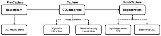
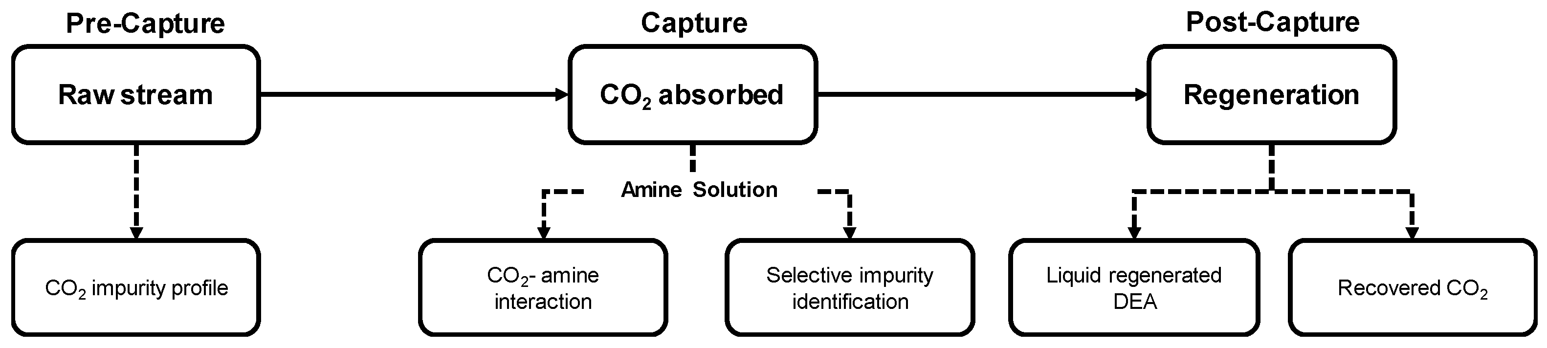
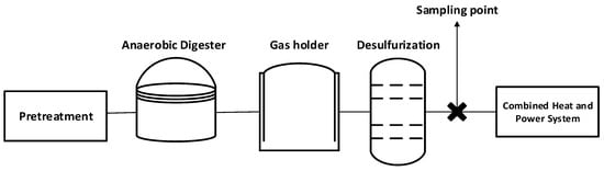
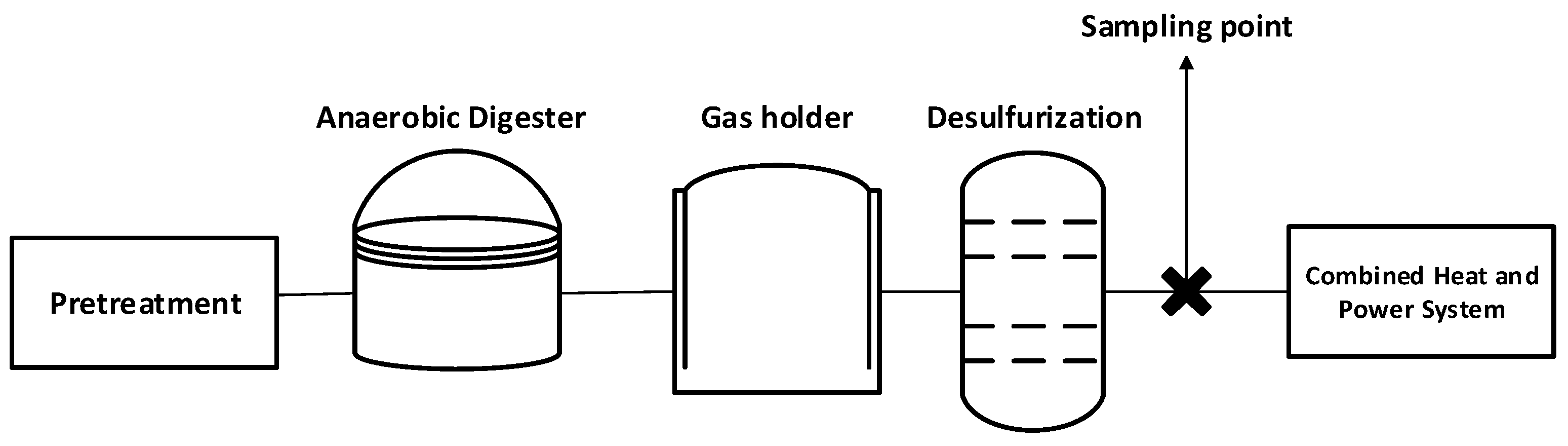
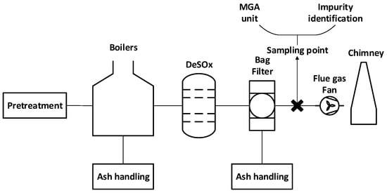
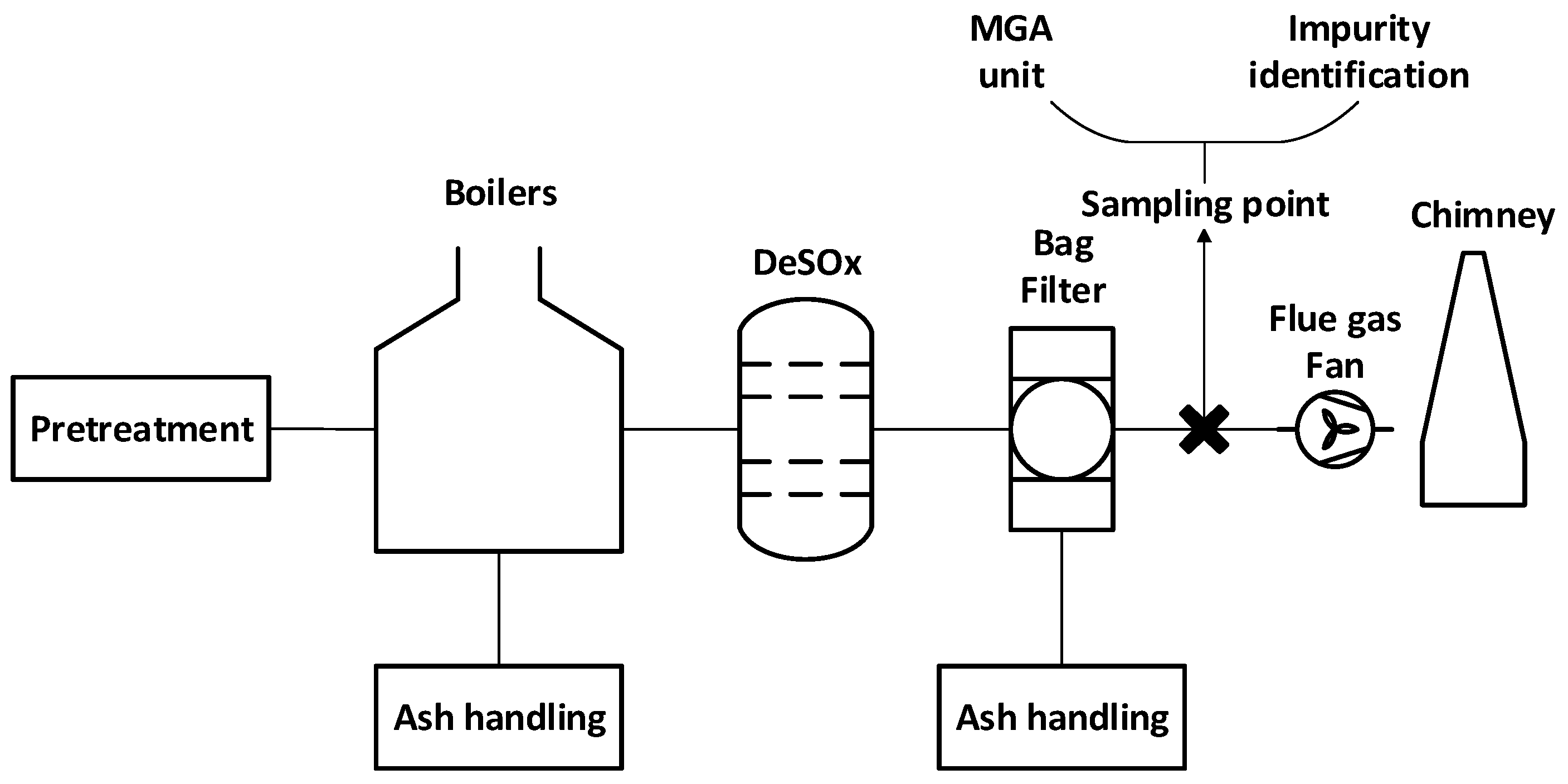
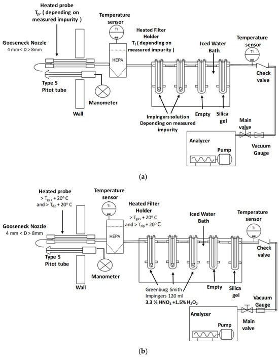
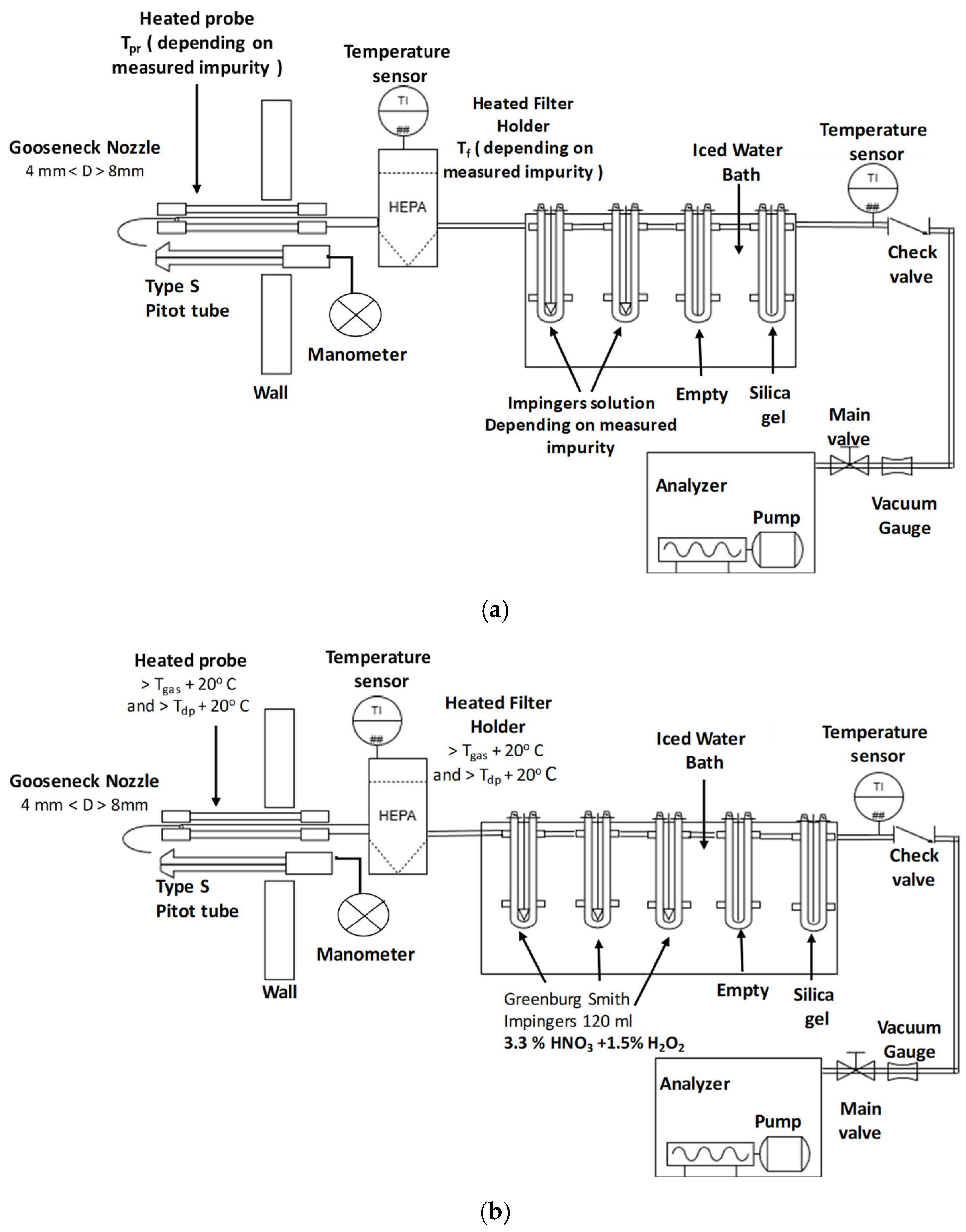
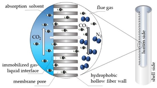
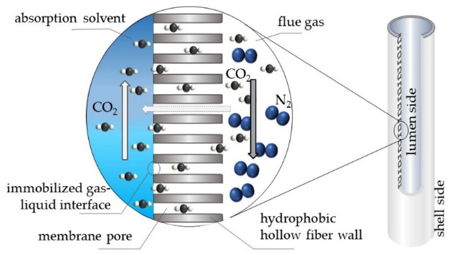
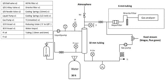
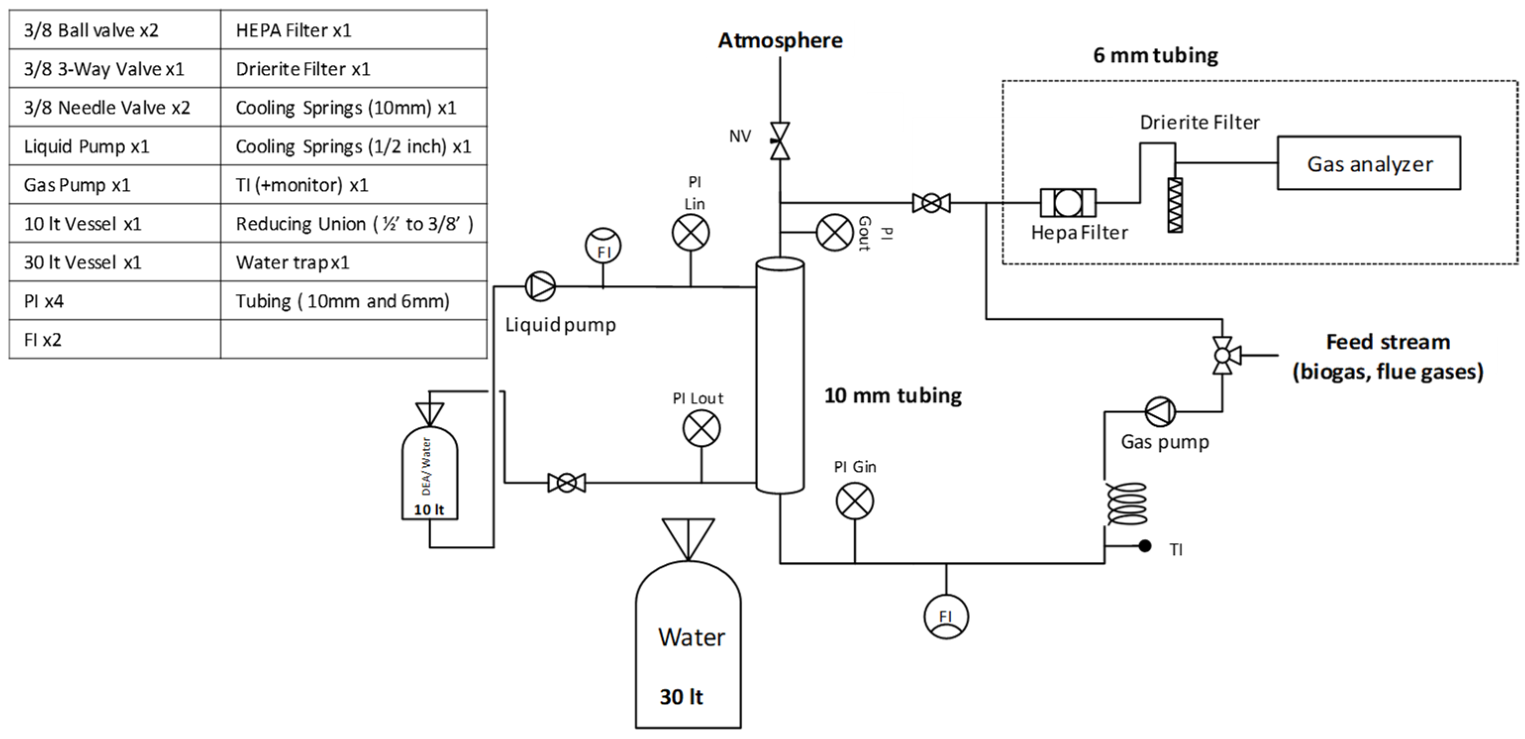
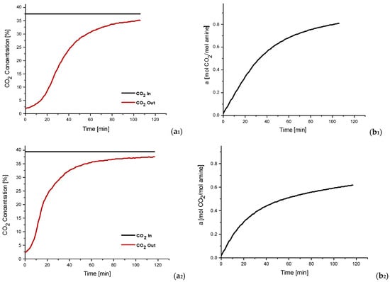
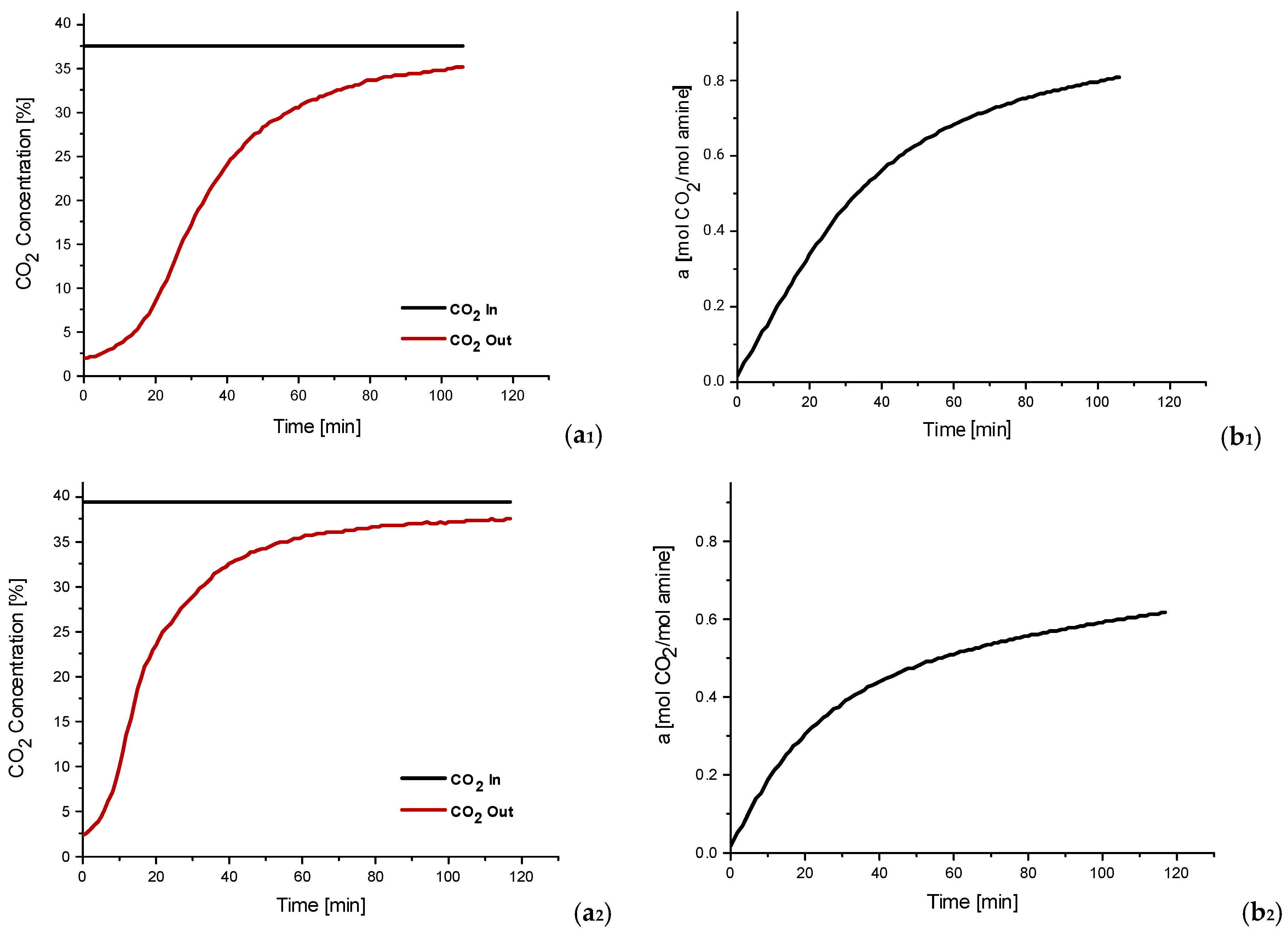
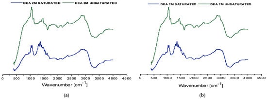
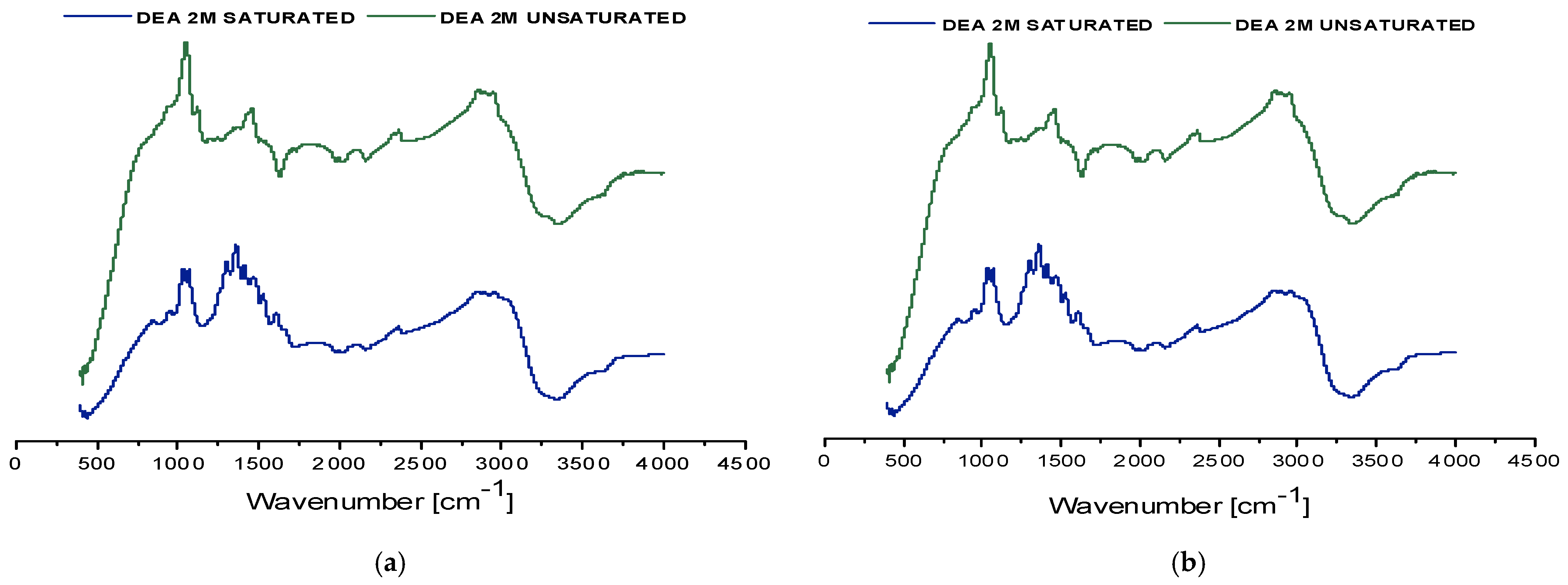
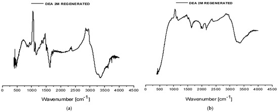
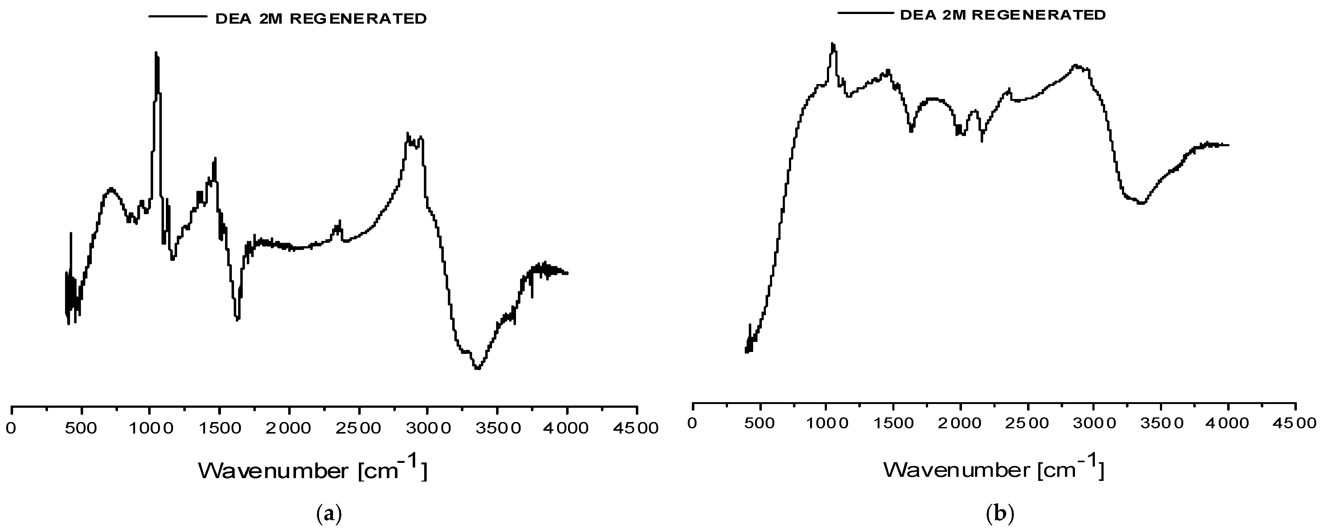
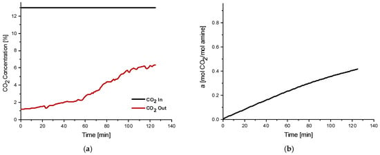
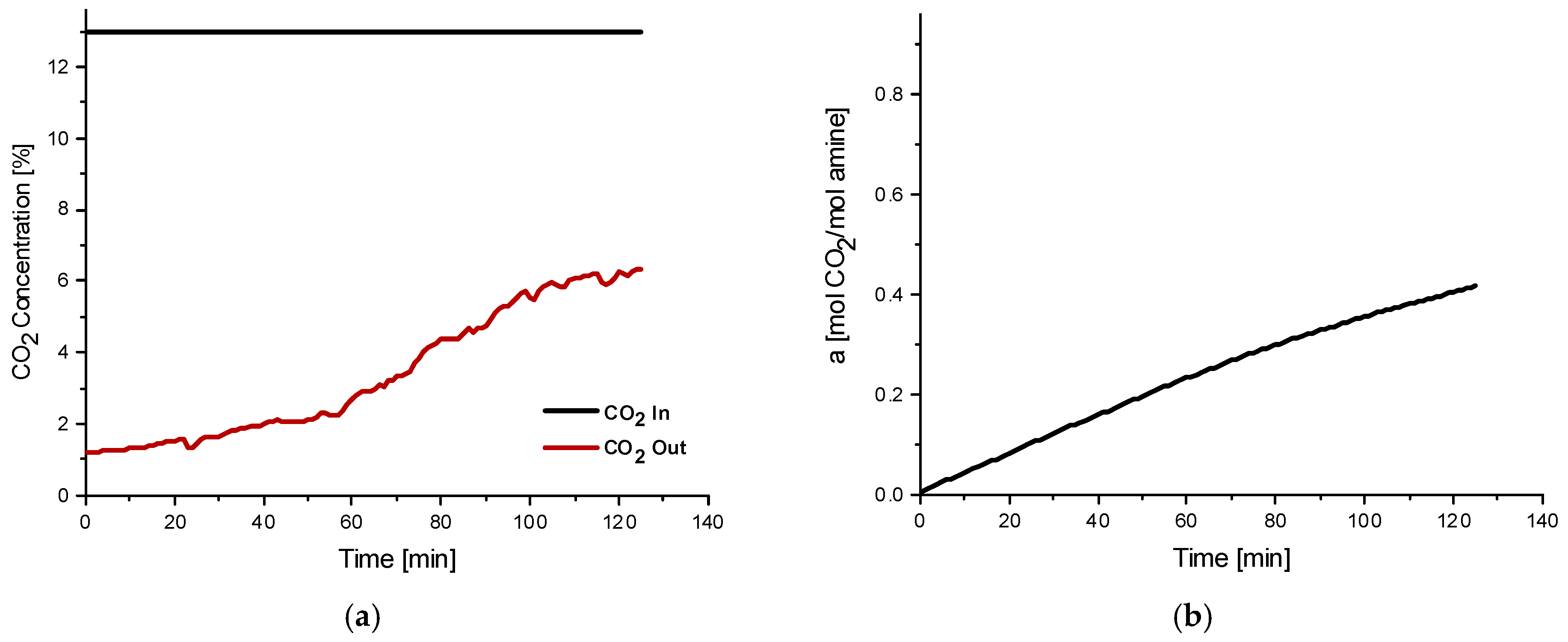
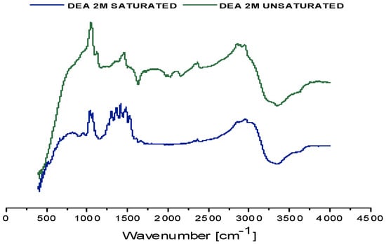
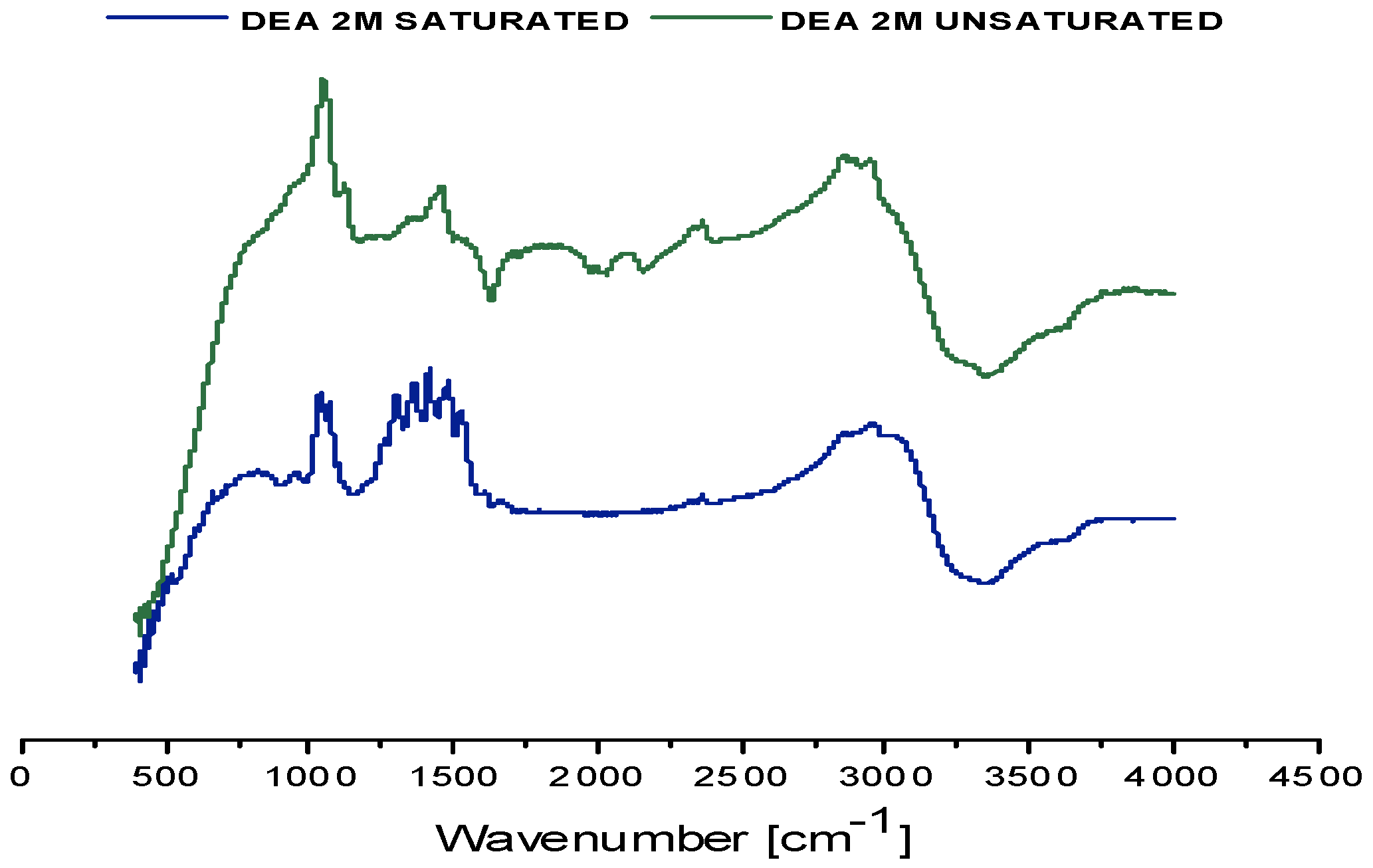
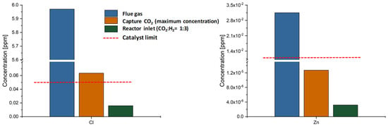
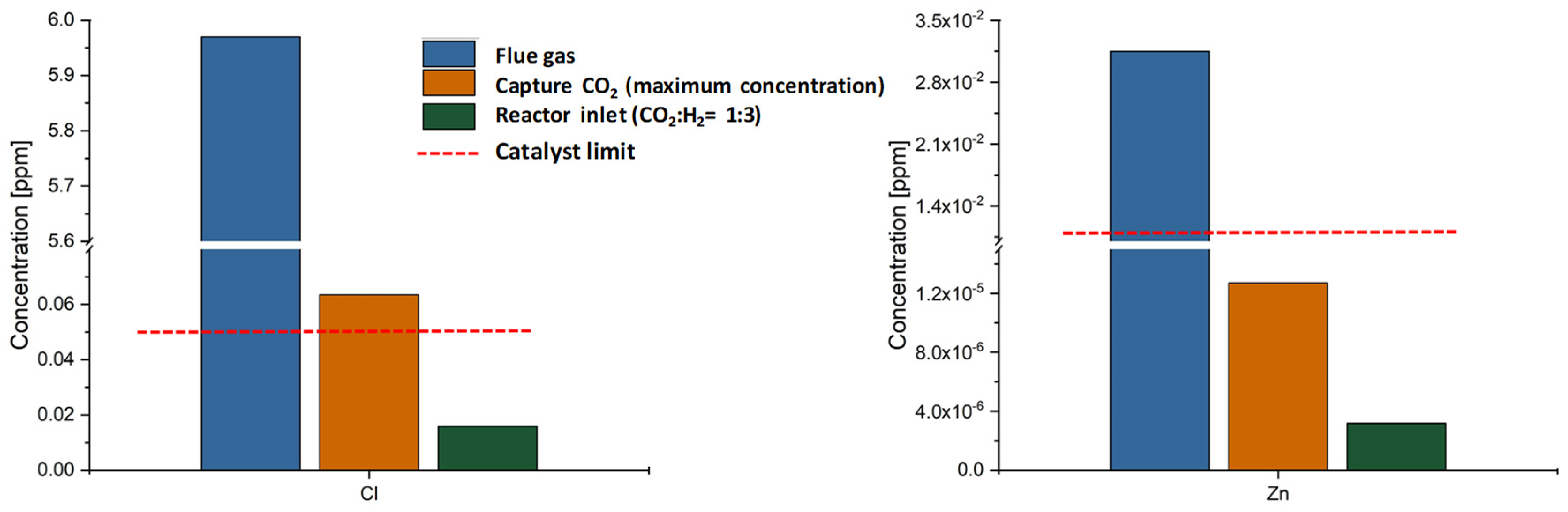
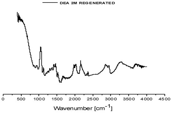
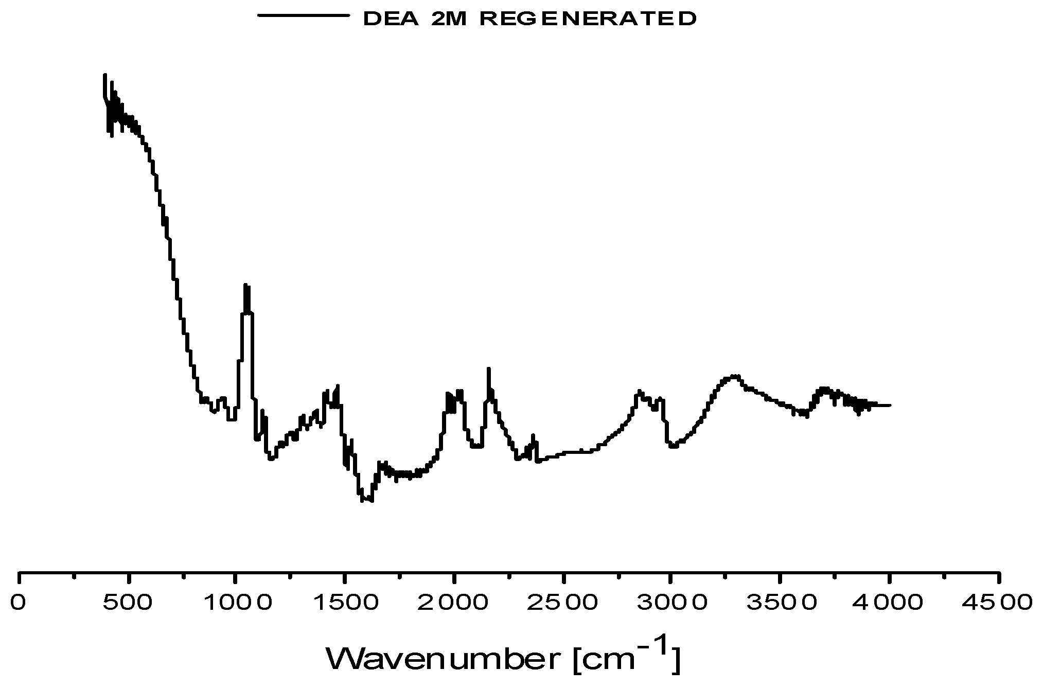

Disclaimer/Publisher’s Note: The statements, opinions and data contained in all publications are solely those of the individual author(s) and contributor(s) and not of MDPI and/or the editor(s). MDPI and/or the editor(s) disclaim responsibility for any injury to people or property resulting from any ideas, methods, instructions or products referred to in the content. |
© 2026 by the authors. Licensee MDPI, Basel, Switzerland. This article is an open access article distributed under the terms and conditions of the Creative Commons Attribution (CC BY) license.