


Abstract
Measuring the mass and Center of Gravity (CG) of rigid bodies with a multi-point weighing method is widely used nowadays. Traditional methods usually include two parts with a certain location, i.e., a fixed platform and a mobile platform. In this paper, a novel structure is proposed to adjust the mobile platform for eliminating side forces which may load on the load cells. In addition, closed-form equations are formulated to evaluate the performance of the structure, and transformation matrices are used to estimate the characteristics of the structure. Simulation results demonstrate that repeatability of the proposed structure is higher than the traditional one and there are no side forces. Moreover, the measurement results show that the relative error of mass was within 0.05%, and the error of CG was within ±0.3 mm. The structure presented in this paper provides a foundation for practical applications.
1. Introduction
Mass and Center of Gravity (CG) are prerequisite parameters when designing the dynamic performance of an aerospace vehicle, car, etc. [1,2]. When the shape of the vehicle is complicated, it is necessary to obtain mass and CG by experiments [3]. The mass can be achieved by weighing machines, for instance, load cells. There are several methods to measure the CG, which can be roughly classified into three categories as follows: (1) static method such as multi-point weighing method or unbalance moment method [1,4,5], (2) dynamic method such as spin balance method or inverted torsion pendulum method [6,7,8,9], and (3) other methods such as the photogrammetric technique for determination of the CG for large scale objects [10].
Each of these methods has its own strengths and weaknesses. For instance, the multi-point weighing method, which uses three or more load cells to support a test platform, has been widely used, and the reason is that this method can measure the mass and CG simultaneously. This method only depends on gravity force acting through the CG, and CG location is calculated by static equilibrium from the reaction forces on the load cells [1,4]. Due to these reasons, it is the most suitable method for some massive objects [4], and it is also the cheapest automatic system.
However, there are shortcomings in the multi-point weighing method, for example, a load cell is a spring and has a designed loading axis. In addition, the generated force against the load cell outside of this axis can result in errors and may shorten the operating life of the load cell [11,12,13,14]. Besides, the measurement accuracy of CG is related to the position of the loading force.
There are several types of load cells or bears to avoid incorrect loading, such as self-centering pendulum load cell, pendulum bearing, and pendulum supports. These load cells automatically guide the superstructure back to its original position when the load is introduced with lateral displacement [15]. However, these methods are usually used for a single load cell. Towards the multi-point weighing method where three or more load cells need to be coupled, no related literatures report the measurement structure.
In order to achieve high accuracy when measuring mass and CG, optimizing the mechanical structure to make the force load on the designed axis is necessary. This paper focuses on designing a structure used in a multi-point weighing method to avoid lateral forces and get high repeatability. Moreover, mathematical modeling of the structure is further established to analyze the proposed method. Finally, simulation and experiment results are conducted to validate the effectiveness of the proposed method.
2. Background and Related Work
2.1. Method for Obtaining the Mass and CG of a Body
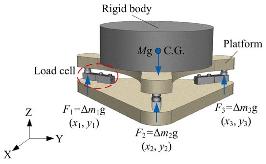
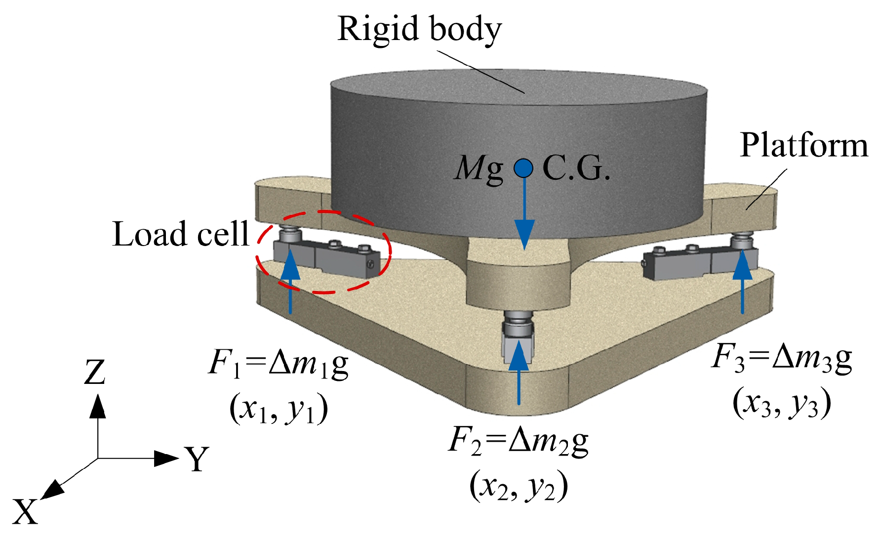
As shown in Figure 1, the multi-point weighing method is a static method, which includes three load cells and a support platform. These three load cells are placed on the same horizontal flat and angularly spaced by 120°. This proposed method depends only on gravity force acting through the CG [1,4].
Figure 1.
Diagram of the multi-point weighing method.
We record the readings of the three load cells, and the sum of the three load cell readings is the mass of the whole system. Similarly, we also record the mass of the system without the rigid body, and the mass of the rigid body is obtained from the difference of the readings shown in Equation (1).
where: M is the mass of the rigid body, and , , are the difference readings of the three load cells.
Based on the static equilibrium (first law), the CG location can be obtained by Equation (2).
According to Equation (1) and Equation (2), there are two factors affecting the accuracy of the results.
(a) Accuracy of the load cell.
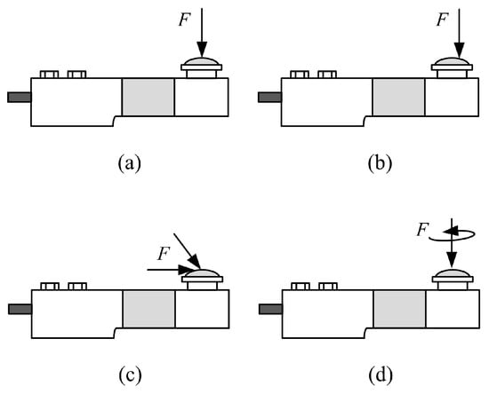
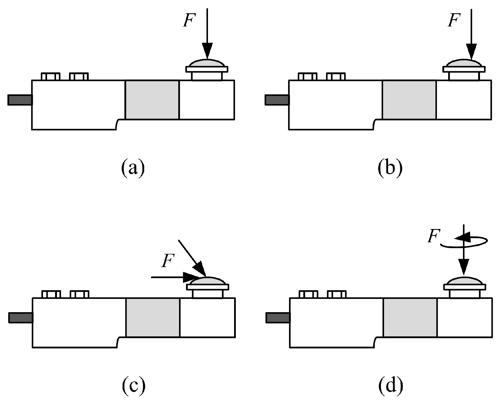
The load cell is sensitive to side forces, bending and torsional moments, which should be avoided in the measurement systems [11,12,13,14,15,16]. Figure 2 shows some examples of correct loading as well as incorrect loading methods on a load cell [13,14,15].
Figure 2.
Correct loading on a load cell and some examples of incorrect loading. (a) Central load application; (b) Non-central load application; (c) Non-axial load application or side forces; (d) Moment-loading (torsion) load application.
(b) Location of the reaction forces (F1, F2 and F3) of the load cells.
The load cell always has a designed axis of loading. If the location of the reaction force is out of this designed axis, it will cause errors of the load cells’ readings, and errors of the CG results can be calculated according to Equation (2).
To avoid these issues, some efforts are done by designing the structure act on the load cell properly.
2.2. Traditional Structure and the Improved Struture
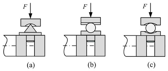
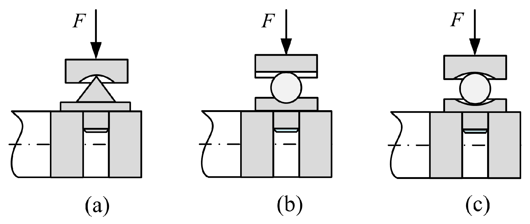
Figure 3 shows some types of structure. (a) Cone joint with conical pan, which is a traditional mounting and it is used for individual load cells, (b) and (c) are types of rocker bearings. The distortion of the load cell’s reading is practically absent for rocker bearings, because in this case only slight rolling friction is present instead of a bending stress. However, the horizontal restraint of the rocker bearing is significantly less than fixed bearings. Rocker bearings are recommended if the position of the superstructure only changes horizontally [15].
Figure 3.
The construction of the traditional structure. (a) Cone joint with conical pan; (b) Ball joint with groove; (c) Ball joint with fillet.
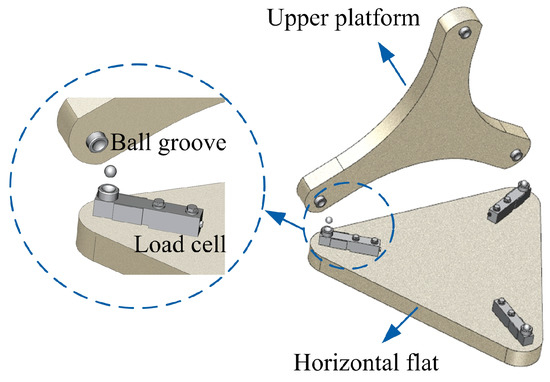
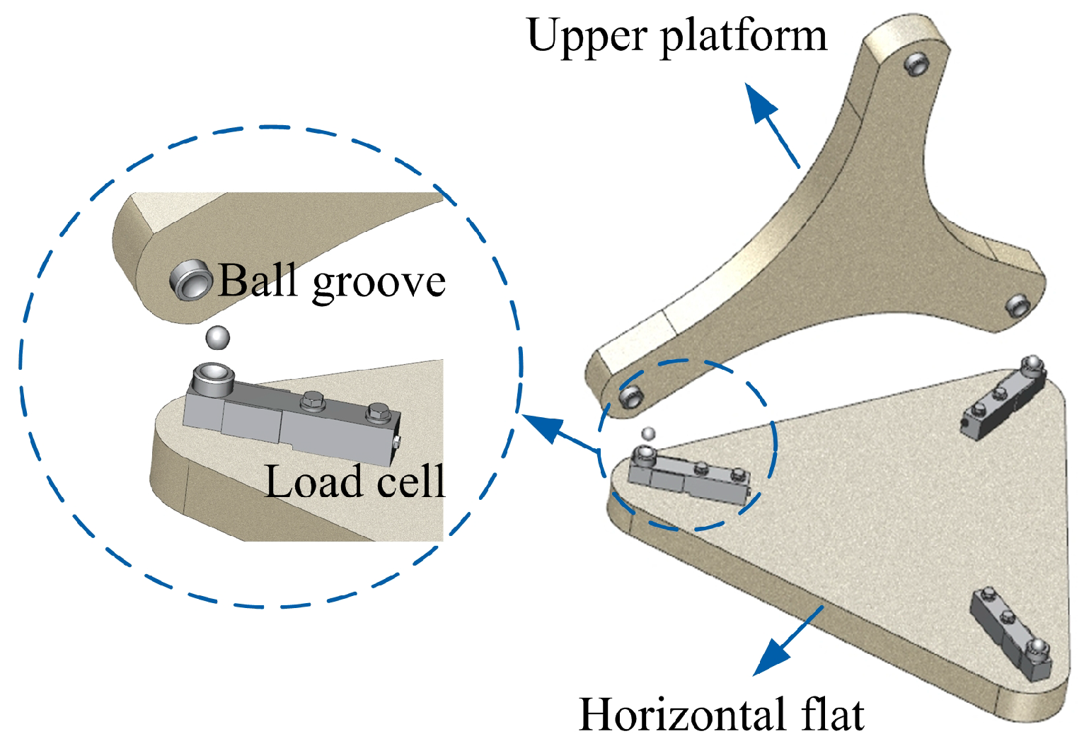
We have researched CG determination for many years, and one traditional method is placing three load cells on the same horizontal flat, as shown in Figure 4. In particular, each load cell has a ball groove and each groove holds a ball, making the center of the ball groove on the designed axis of the load cell. The upper platform has a similar construction. The ball can stay at the center of the ball groove because of the gravity.
Figure 4.
The construction of the traditional structure.
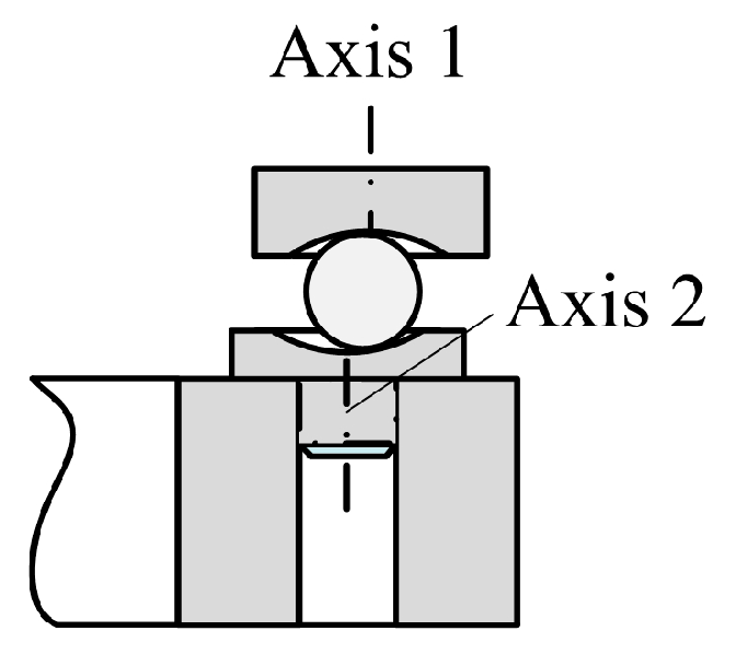
However, due to manufacturing tolerance and imperfect assembly, axis 2 is not the same as axis 1 shown in Figure 5, making it hard to guarantee F pass through each designed axis of the load cell. Moreover, reducing these errors will increase the costs significantly.
Figure 5.
Axes of the ball grooves.
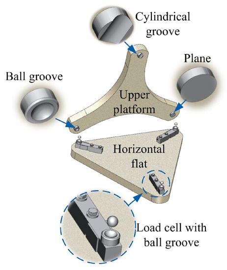
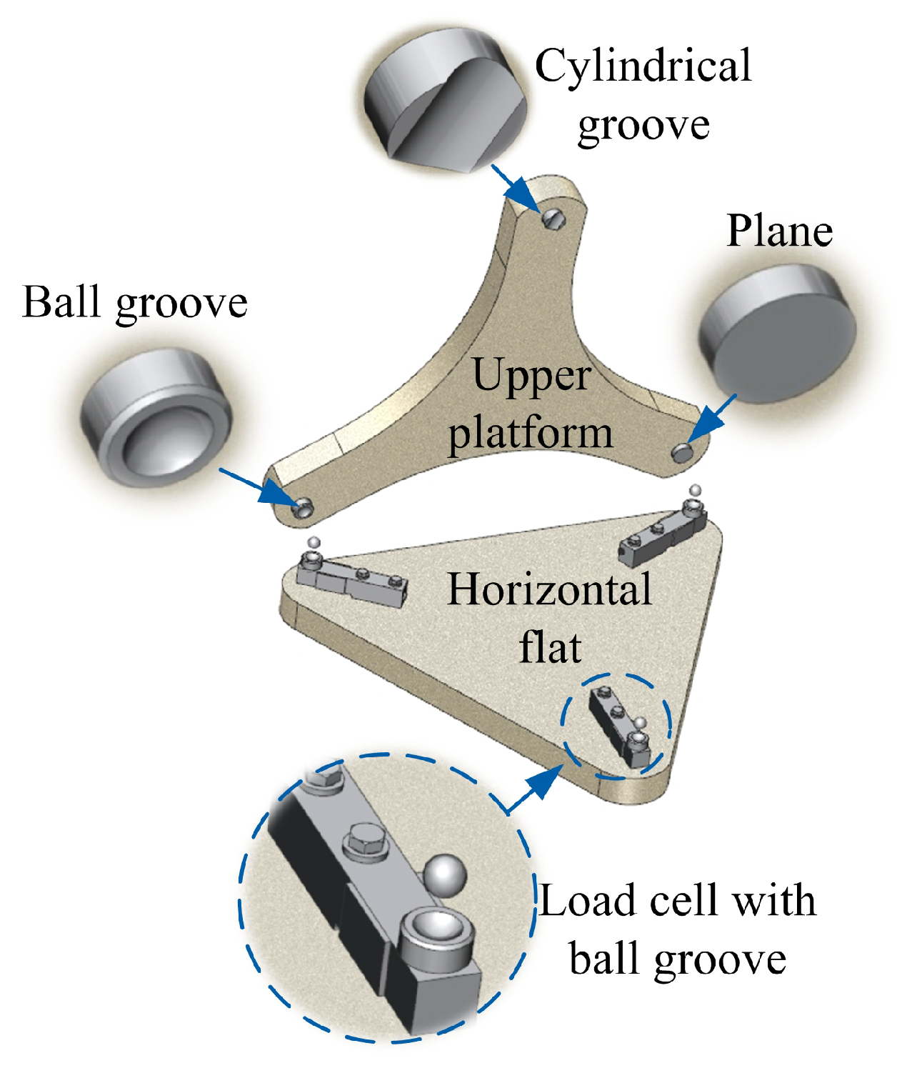
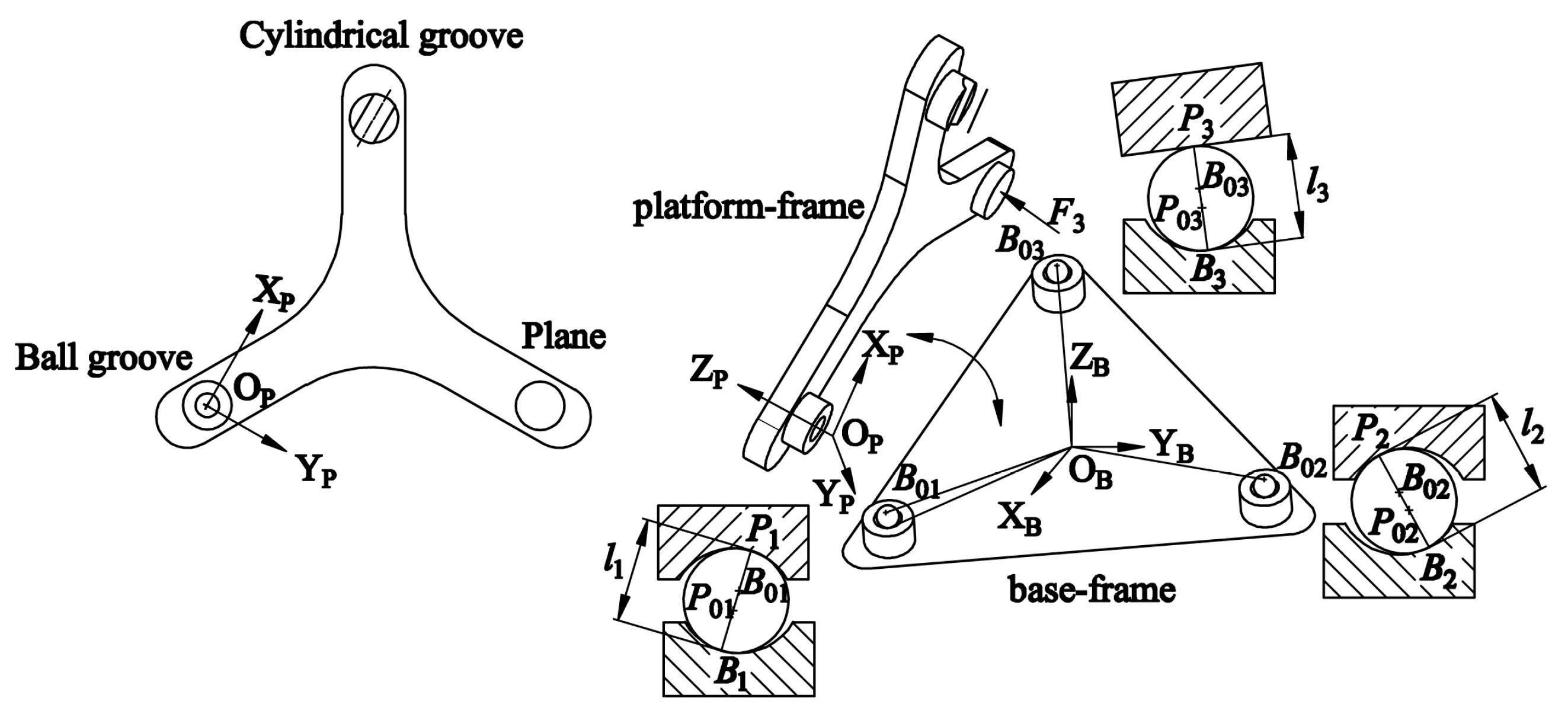
Regarding the above issue, an improved structure is proposed, as shown in Figure 6. Similar to Figure 4, three load cells rest on the base platform, each of them has a ball groove and each groove holds a ball, ensuring the center of the ball groove goes through the designed axis of the load cell. The base platform should be horizontal and this structure should minimize the friction.
Figure 6.
The construction of the new structure.
Specifically, the upper platform has one ball groove, one cylindrical groove and one planar surface. Because of the characteristic of the cylindrical groove and the plane, the upper platform can adjust its position and ensure F passes through the designed axis of the load cell without side force, even though these grooves may have position errors. A mathematical analysis of the structure will be performed in the next part.
3. Parametric Representation of the Structure
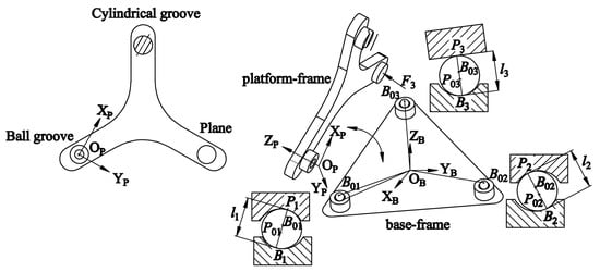
Here, for a convenient and simple explanation, the platform with the load cells is called the base-frame, and the upper platform is called the platform-frame [17]. The base-frame (OB,XB,YB,ZB) and the platform-frame (OP,XP,YP,ZP) are two right-handed orthonormal coordinate systems with (XB,YB,ZB) and (XP,YP,ZP) as their bases respectively, as shown in Figure 7. The three centers of ball grooves, which are held by load cells, always rest on the XBYB-plane. The origin OB of the base-platform is the intersection of the bisectors of the three angles of the base frame triangle. Coordinates of the centers of the ball grooves formulate the locations of the ball grooves.
Figure 7.
The schematic of the structure.
The origin OP of the platform-frame is the center of the ball groove shown in Figure 7, and the XP axis is parallel with the axis of the cylindrical groove. The plane is parallel with the XPYP-plane. In the neutral configuration, the platform-frame has a general position and rotation with respect to the base-frame.
It is assumed that the external force acting on the platform-frame is known as well as the positions of the load cells, and it is assumed that Bi (i = 1, 2, 3) and Pi (i = 1, 2, 3) are unknowns. The significance of modeling is to analyze whether directions of (i = 1, 2, 3) are vertical to the XBYB-plane, which means that there are no side forces.
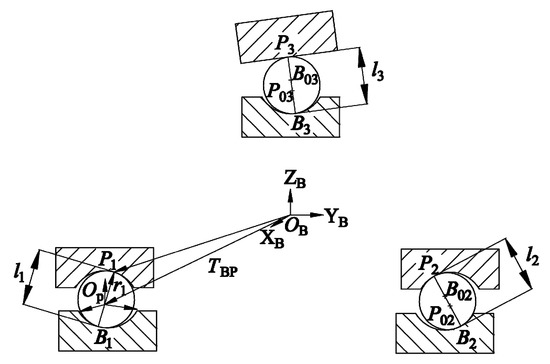
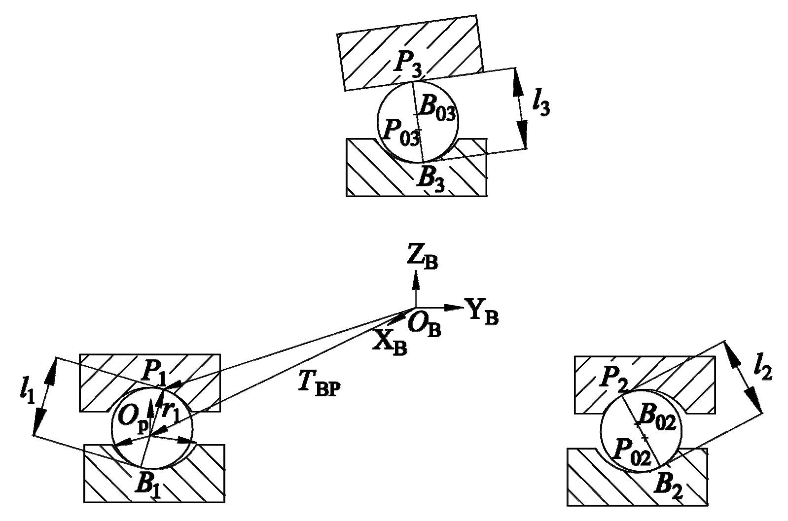
To analyze the structure, the coordinates of Pi (i = 1, 2, 3) or Bi (i = 1, 2, 3) should represent the same coordinate system (OB,XB,YB,ZB), as shown in Figure 8, and Pi in base-frame (OB,XB,YB,ZB) is shown in Equation (3):
where is the relative position vectors between Op-XPYPZP and OB-XBYBZB. RBP is the matrix representation of the rotation between OP-XPYPZP and OB-XBYBZB. P1 is the coordinate of the contact point between the ball and the ball groove; P2 is the coordinate of the contact point between the ball and the cylindrical groove; and P3 is the coordinate of the contact point between the ball and the plane in the platform-frame. is the coordinates of Pi (i = 1, 2, 3) expressed in OB-XBYBZB.
Figure 8.
The vector loop between ball and ball groove.
The rotation matrix RBP is expressed by:
where:
is the direction of (i = 1, 2, 3), which can be described by Equation (6) [17]:
Ignore the effects of friction, the direction of always passes through the centers of the balls. As a result, the magnitudes of are constant, which equal to the diameter of the balls, as shown in Equation (7):
Fi are the forces loading on the load cells, and the direction of Fi expressed in OB-XBYBZB can be expressed by the unit vector , as shown in Equation (8):
While the direction of Fi expressed in OP-XPYPZP can be expressed by the unit vector , as shown in Equation (9):
The stability of the platform-frame must meet two conditions, namely, the force balance theorem and equilibrium of couples [18], which can be formulated in Equation (10):
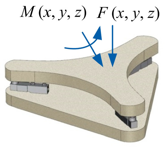
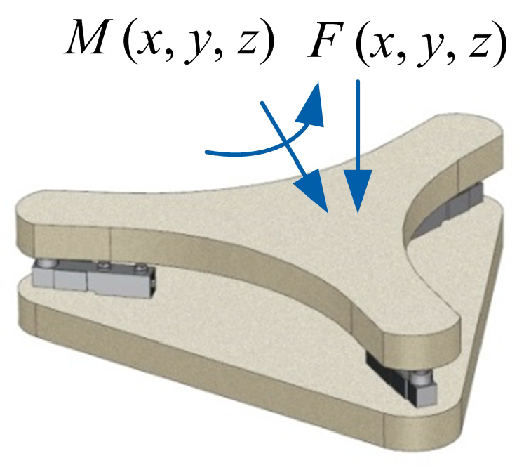
where F and M are the external force and torque respectively, which act on the platform-frame as shown in Figure 9. Here, the (i =1, 2, 3) are formulated as Equation (11):
Figure 9.
External force diagram of the measuring system.
Ignore the effects of friction; the Fi always passes through the centers of the ball grooves so that it rests on the base-frame, so do the . As a result, the coordinates B0i of the centers of the three balls grooves are calculated by Equation (12):
where RB are the radiuses of ball grooves, and Bi are the contact points between the balls and the ball grooves.
Similarly, the orientation of F1 always passes through the center of the ball groove (P01x, P01y, P01z) which lies on the platform-frame, making the center of the ball groove equal to the origin (0, 0, 0) of the OP-XPYPZP, which can be formulated as Equation (13):
where (xP1, yP1, zP1) is the coordinate of P1, which is the contact point between the ball and the ball groove; RP is the radius of the ball groove; (nP1x, nP1y, nP1z) are the vectors of .
The orientation of the (nP2x, nP2y, nP2z) passes through the axis of the cylinder groove, because the axis of the platform (XP) is parallel with the axis of the cylinder groove, as a result, we can get Equation (14):
where (xP2, yP2, zP2) is the coordinate of P2, which is the contact point between the ball and the cylindrical groove; RP is the radius of the cylindrical groove.
Besides, the normal vector of the plane is the orientation of (nP3x, nP3y, nP3z) and is given by Equation (15):
The solution described here uses the geometric model to calculate the relative position and orientation between the base-frame and the platform-frame. Analysis of the unknowns from Equation (3) to Equation (15) will help to analyze the characteristics of the improved structure.
4. Simulation Results and Discussion
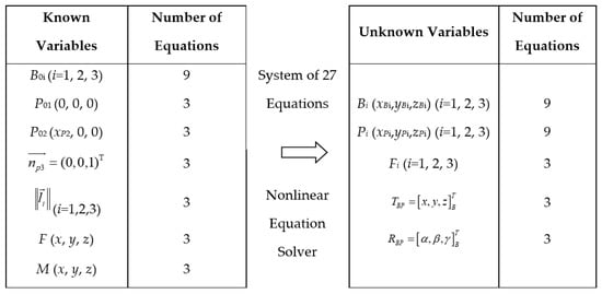
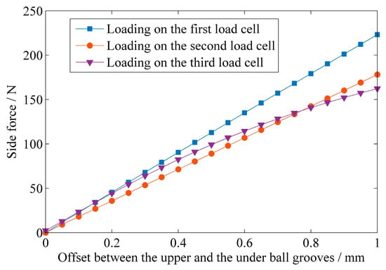
A simulation was carried out to demonstrate the feasibility of the proposed method. As illustrated in Figure 10, the solution employs a system of 27 equations. The corresponding unknown variables were solved iteratively by using a nonlinear numerical technique [19]. The inputs to the solver include B0i, P01, P02, , , F, and M. The outputs of the algorithm include Bi, Pi, Fi, TBP and RBP.
Figure 10.
The solution for the proposed mathematical model.
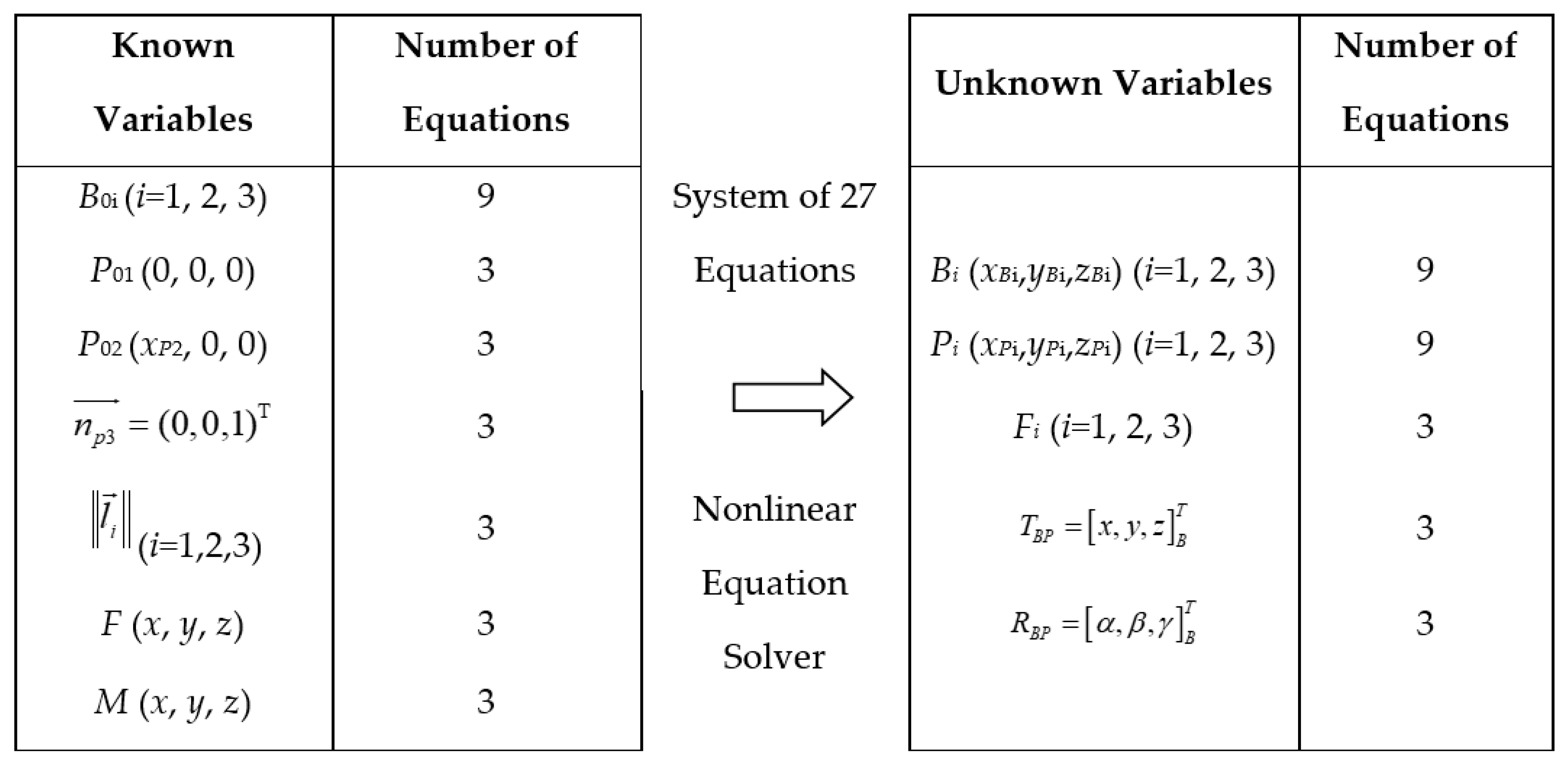
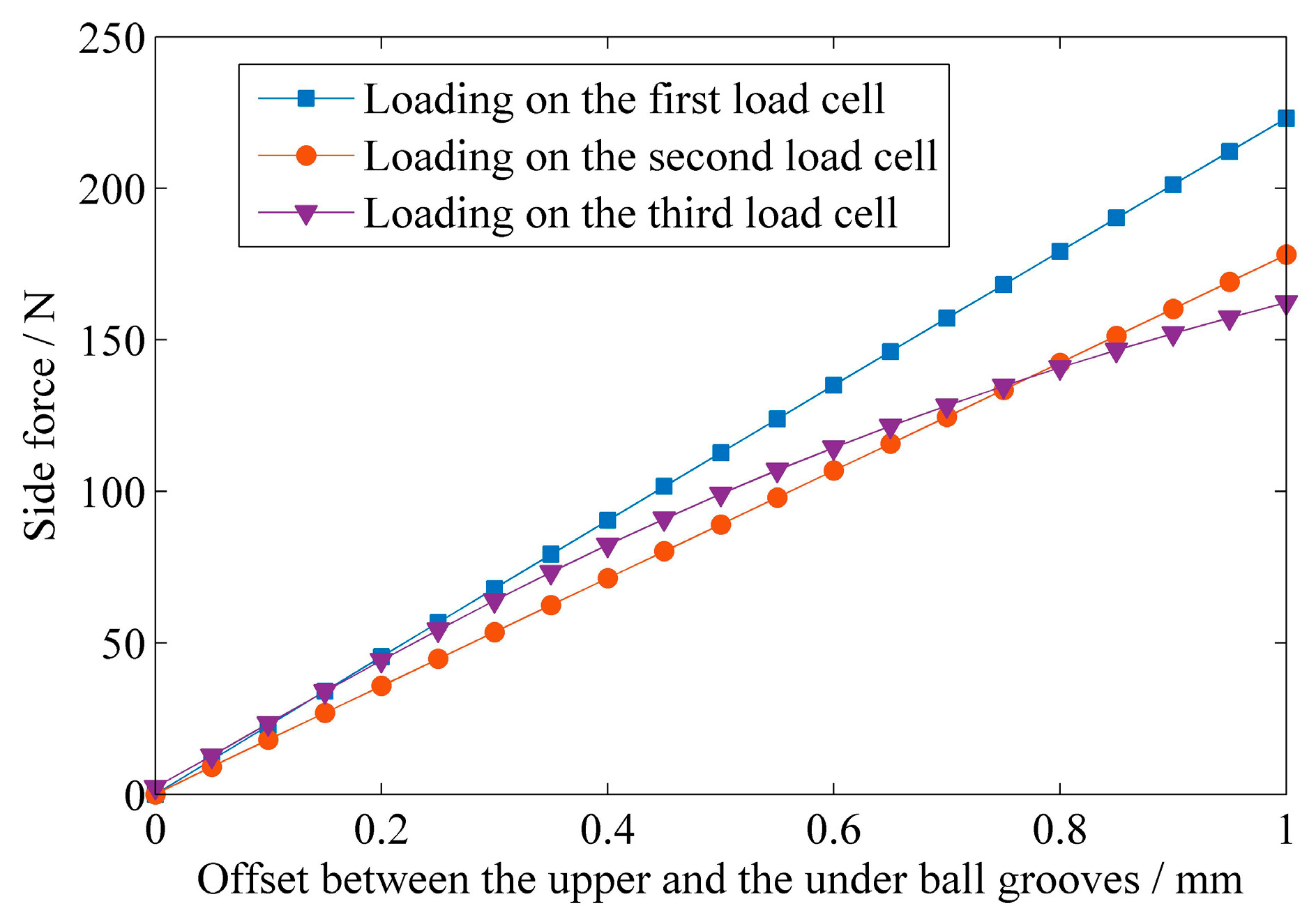
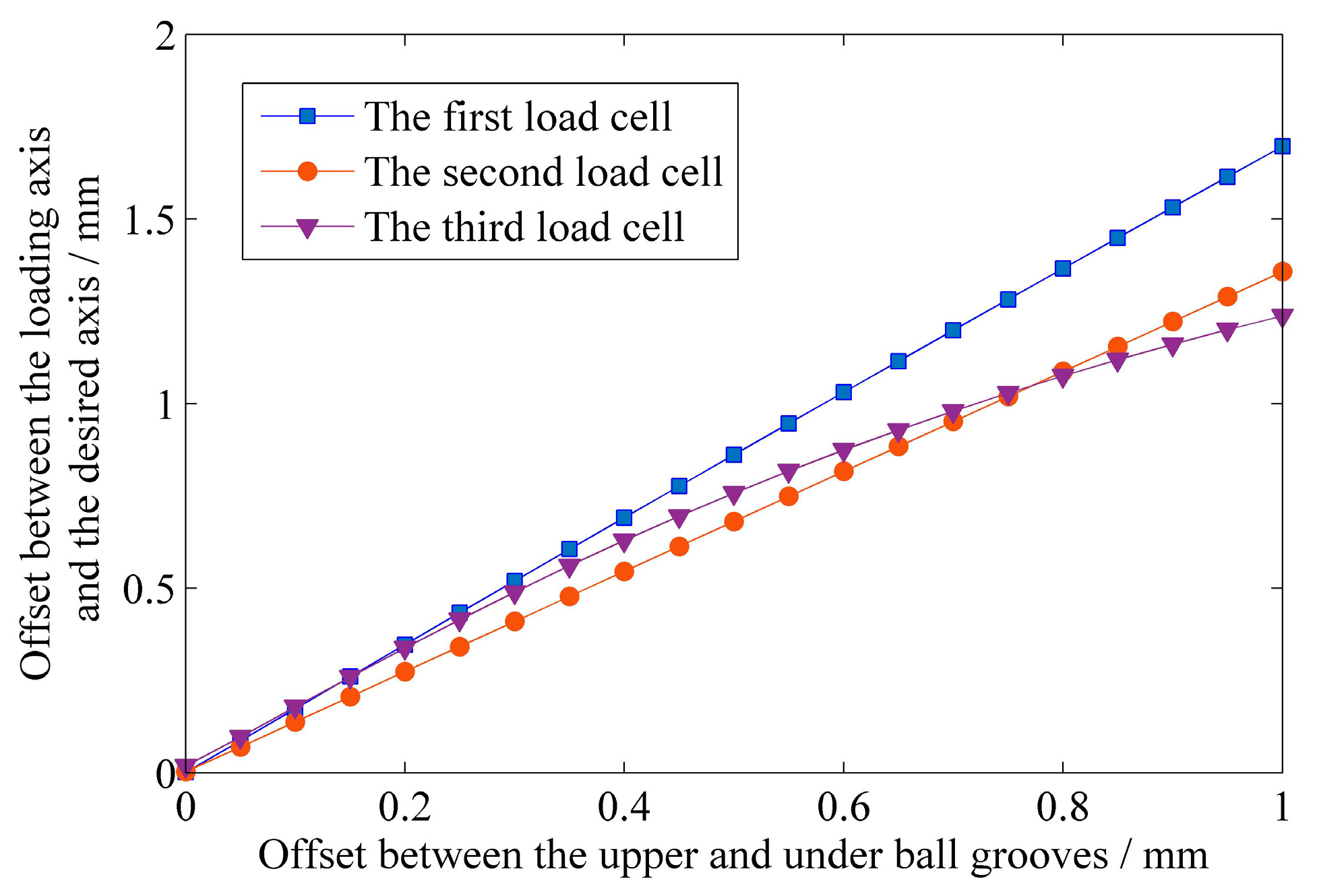
With the proposed mathematical modeling, we analyze the traditional structure. Setting the offsets between axis 1 and axis 2, as shown in Figure 5, to 0 mm, 0.05 mm, 0.10 mm, …, 1.00 mm, the side forces loading on the three load cells were obtained and shown in Figure 11. The offsets of the loading axes between the designed axes are listed in Figure 12. The inputs are listed in Appendix B.
Figure 11.
The simulation results of the side forces.
Figure 12.
The simulation result of offsets between the loading axes and the designed axes.
From Figure 11 and Figure 12, we can see that the traditional structure provides high accuracy without lateral forces in the ideal case. However, when taking the manufacturing or assembling errors into account, i.e., making the axis of the ball grooves on the base-frame shift the axis of ball grooves on the platform-frame, the results show that the offsets of the loading axes between the designed axes increased, so do the side forces.
The improved structure was also analyzed. With the offset or not, the side forces loading on the three load cells were always less than 0.01 N, and the offsets of the loading axes between the designed axes were less than 0.001 mm, which means that the accuracy of the improved method is higher than the traditional one.
5. Physical Experiments
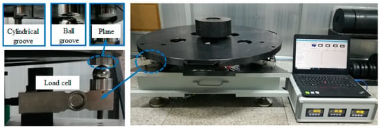
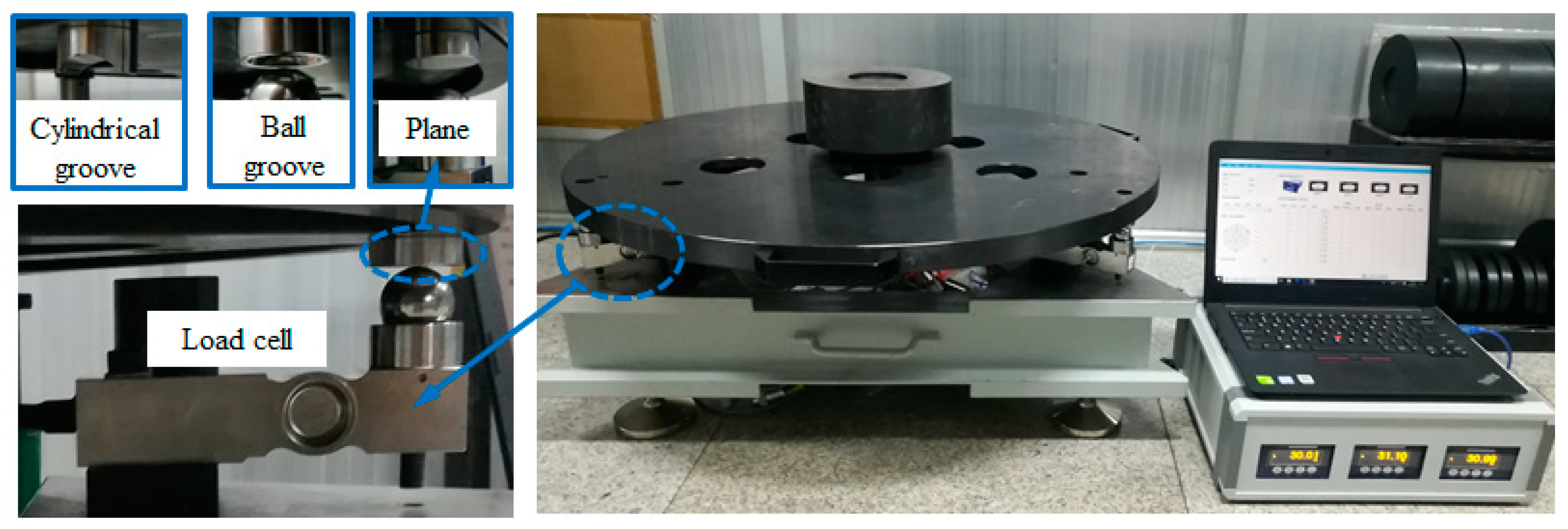
Mass and CG of a sample were measured 20 times with the traditional structure and the improved one respectively, as shown in Figure 13, and the standard deviations of the data are listed in Table 1, which means that the new structure has higher repeatability. The accuracy of the load cell is 0.02%, and the range of the load cell is (0–220) kg.
Figure 13.
Experiment platform for measuring mass and CG.
Table 1.
The standard deviations of the mass and the CG.
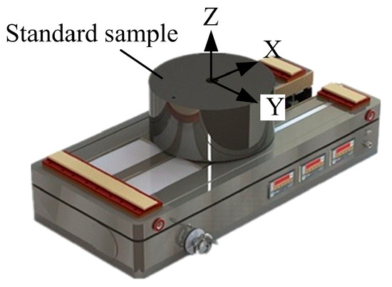
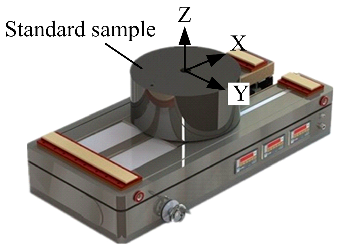
Mass and CG of a large-sized standard sample was measured by a system with the new structure as shown in Figure 14. Major dimensions of the system are shown in Table 2, and the specification and design requirements of the system are shown in Table 3.
Figure 14.
Experimental platform for measuring the mass and CG.
Table 2.
Major dimensions of the system.
Table 3.
Specification and design requirements of the system.
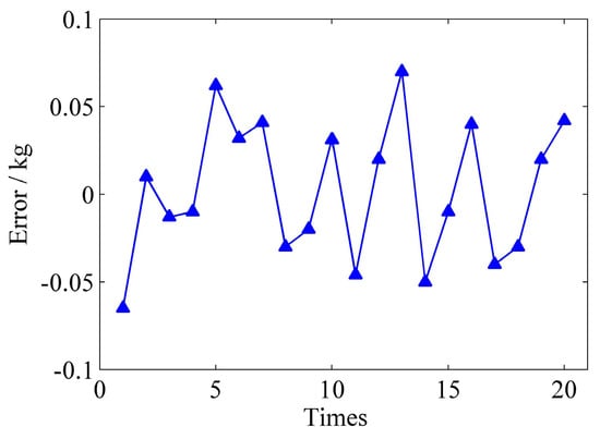
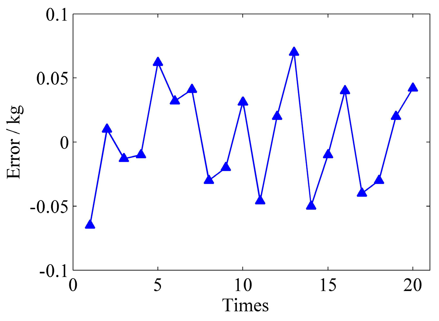
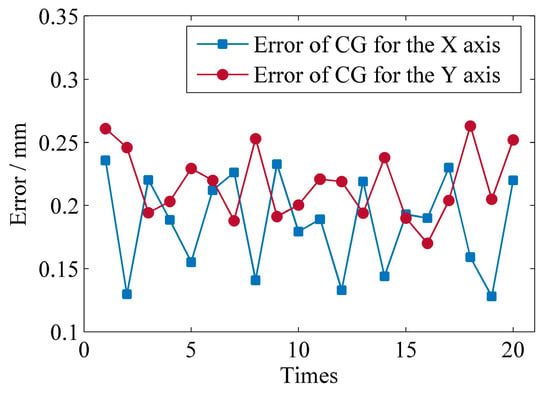
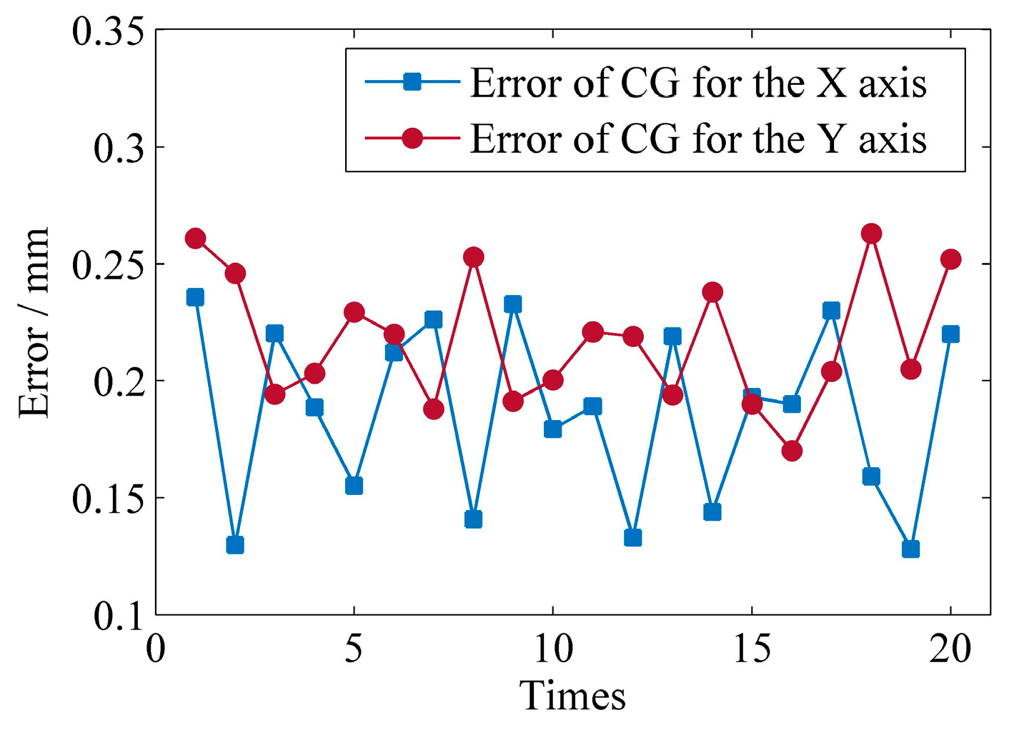
The mass and CG of this sample have been calibrated by a metrological authority. According to the calibration result, the mass is 779.43 kg, and the offset of CG from the centroid of the sample is less than 0.05 mm. The standard sample was placed at 20 different positions of the measurement system. The mass errors measured by the system are shown in Figure 15, and the CG errors are shown in Figure 16.
Figure 15.
The measurement error of mass.
Figure 16.
The measurement error of the CG.
According to the results of the mass measurement, the standard deviation of mass is 0.05 kg, and the maximum error is −0.07 kg. Meanwhile, the standard deviation of the CG along X axis is 0.04 mm, and the standard deviation of the CG along Y axis is 0.05 mm, which means that the improved structure can be used to measure the mass and CG with high accuracy.
6. Conclusions and Outlook
An improved structure for measuring the mass and CG was proposed in this paper. In addition, the analysis of the structure was presented, which includes the position and orientation of the platform-frame. Simulation and experimental results illustrate that the repeatability of the proposed structure is higher than the traditional one. In future work, the deflection deformation of the balls and the friction between the balls and the grooves will be considered, and the optimal radiuses of the grooves and the balls will be considered too.
Author Contributions
Conceived the Method and Edited the Manuscript, X.Z.; Conceived the Method, Designed, Performed the Experiments and Wrote the Paper M.W. Conceived the Method and Designed the Experiments W.T. Performed the Experiments, J.W.
Funding
This study was funded by Shanghai Aerospace Science and Technology Innovation Foundation (SAST2015029).
Acknowledgments
The authors would like to thank the associate editor and the reviewers for their helpful comments, which improved the quality of this paper.
Conflicts of Interest
The authors declare no conflicts of interest.
Appendix A
Table A1.
Variables and their description.
Appendix B
Table A2.
Inputs and their values.
References
- Mondal, N.; Acharyya, S.; Saha, R.; Sanyal, D.; Majumdar, K. Optimum design of mounting components of a mass property measurement system. Measurement 2016, 78, 309–321. [Google Scholar] [CrossRef] [Scilit]
- Previati, G.; Gobbi, M.; Mastinu, G. Measurement of the mass properties of rigid bodies by means of multi-filar pendulums—Influence of test rig flexibility. Mech. Syst. Signal Process. 2019, 121, 31–43. [Google Scholar] [CrossRef] [Scilit]
- Tang, L.; Shangguan, W.B. An improved pendulum method for the determination of the center of gravity and inertia tensor for irregular-shaped bodies. Measurement 2011, 44, 1849–1859. [Google Scholar] [CrossRef] [Scilit]
- Gopinath, K.; Raghavendra, K.; Behera, M.K.; Rao, E.V.; Umakanth, M.; Gopinath, S. Product design aspects for design of accurate mass properties measurement system for aerospace vehicles. Appl. Mech. Mater. 2012, 110–116, 4712–4718. [Google Scholar] [CrossRef] [Scilit]
- Fabbri, A.; Molari, G. Static measurement of the centre of gravity height on narrow-track agricultural tractors. Biosyst. Eng. 2004, 87, 299–304. [Google Scholar] [CrossRef] [Scilit]
- Liu, Y.; Liang, B.; Xu, W.; Wang, X. A method for measuring the inertia properties of a rigid body using 3-URU parallel mechanism. Mech. Syst. Signal Process. 2019, 123, 174–191. [Google Scholar] [CrossRef] [Scilit]
- Brancati, R.; Russo, R.; Savino, S. Method and equipment for inertia parameter identification. Mech. Syst. Signal Process. 2010, 24, 29–40. [Google Scholar] [CrossRef] [Scilit]
- Hou, Z.C.; Lu, Y.N.; Lao, Y.X.; Liu, D. A new trifilar pendulum approach to identify all inertia parameters of a rigid body or assembly. Mech. Mach. Theory 2009, 44, 1270–1280. [Google Scholar] [CrossRef] [Scilit]
- Gobbi, M.; Mastinun, G.; Previati, G. A method for measuring the inertia properties of rigid bodies. Mech. Syst. Signal Process. 2011, 25, 305–318. [Google Scholar] [CrossRef] [Scilit]
- NASA Technical Report Server. Photogrammetric Technique for Center of Gravity Determination. AIAA. Available online: https://ntrs.nasa.gov/search.jsp?R=20120008800 (accessed on 23 April 2012).
- NASA Technical Report Server. Training for a New Spacecraft Center of Gravity. Available online: https://nasasearch.nasa.gov/search?query=center+of+garvity&affiliate=nasa&utf8=%E2%9C%93 (accessed on 1 May 2013).
- Peterson, E. Control of Side-Loads and Errors When Weighing on Jacks. In Proceedings of the 59th Annual International Conference on Mass Properties Engineering, St. Louis, MO, USA, 5–7 June 2000. [Google Scholar]
- OMEGA. Installing a Load Cell: Best Practices. Available online: https://www.omega.com/technical-learning/load-cell-installation.html (accessed on 1 September 2018).
- OMEGA. Load Cell Installation Guide. Available online: https://www.omega.co.uk/technical-learning/load-cell-installation.html (accessed on 7 September 2016).
- HBM. Load Application in Load Cells—Tips for Users. Available online: https://www.hbm.com/en/3377/load-application-in-load-cells/ (accessed on 30 April 2018).
- Wei, T.P.; Yang, X.X.; Yao, J.H.; Xu, H. The additional side force on the force transducer in the combinatorial load cell. AMM 2014, 541–542, 1327–1332. [Google Scholar] [CrossRef] [Scilit]
- Afzali-Far, B.; Andersson, A.; Nilsson, K.; Lidström, P. Dynamic isotropy in 6-DOF kinematically constrained platforms by three elastic nodal joints. Precis. Eng. 2016, 45, 342–358. [Google Scholar] [CrossRef] [Scilit]
- Schmiechen, P.; Slocum, A.H. Analysis of kinematic systems: A generalized approach. Precis. Eng. 1996, 19, 11–18. [Google Scholar] [CrossRef] [Scilit]
- Barraja, M.; Vallance, R.R. Tolerancing kinematic couplings. Precis. Eng. 2005, 29, 101–112. [Google Scholar] [CrossRef] [Scilit]


© 2019 by the authors. Licensee MDPI, Basel, Switzerland. This article is an open access article distributed under the terms and conditions of the Creative Commons Attribution (CC BY) license (http://creativecommons.org/licenses/by/4.0/).