


Abstract
Horizontal well drilling is the mainstream technology for developing deep oil and gas resources. Engineering practice has demonstrated that hydraulic oscillators can solve the problem of the backing pressure of pipe strings and improve drilling efficiency. However, the design of excitation parameters for hydraulic oscillators is currently largely based on idealized friction models and does not fully consider the nonlinear characteristics of friction between the drill string and the formation, resulting in a lack of quantitative basis for parameter selection under different operating conditions. A series of laboratory friction tests was conducted to systematically characterize the dependence of interfacial friction behavior on sliding velocity across different combinations of drill string materials, drilling fluid systems, and rock lithologies. Based on the experimentally determined velocity–friction relationships, a drill string dynamic model incorporating a hydraulic oscillator was developed in which nonlinear frictional effects at the interface were explicitly represented. Using this modeling framework, parametric simulations were carried out to examine how variations in excitation amplitude and excitation frequency influence drag reduction performance under diverse operating conditions. The simulation results indicate that the contribution of drill string material to overall drag reduction effectiveness is comparatively limited, whereas drilling fluid type plays a dominant regulatory role. Oil-based drilling fluids significantly enhance drag reduction performance relative to water-based systems and exhibit greater responsiveness to adjustments in excitation parameters. Rock lithology exerts a pronounced influence on the effectiveness of drag reduction. When water-based drilling fluids are used, the overall performance ranks from highest to lowest as limestone, shale, and sandstone. In contrast, under oil-based drilling fluid conditions, the relative ordering shifts to shale, followed by sandstone, and then limestone. Excitation amplitude is the dominant parameter in enhancing drag reduction capability, and in most cases, its incremental effect exceeds that of excitation frequency; however, under certain specific operating conditions, increasing the excitation frequency can provide additional drag reduction benefits. Based on the above findings, a hydraulic oscillator excitation parameter design method was proposed that matches drilling conditions and formation characteristics by distinguishing between different drilling fluid environments and lithologies, with amplitude as the primary control parameter and frequency as a supplementary parameter. This method provides a theoretical foundation for the design of output parameters of hydraulic oscillators operating under diverse working conditions.
1. Introduction
As conventional oil and gas reserves continue to decline, exploration and production efforts are progressively moving toward deeper and ultra-deep geological formations. Owing to their larger reservoir contact area and higher single-well productivity, horizontal wells and extended-reach wells have become the principal well types for unconventional resource development [1,2,3]. In recent years, the scale of long horizontal section drilling has continued to expand, with horizontal intervals in certain blocks reaching up to 4 km in length [4]. The extension of horizontal sections significantly increases the contact length between the drill string and the wellbore wall, resulting in a sharp rise in frictional resistance and increasingly severe drag and compression (axial drag accumulation) problems. Consequently, weight-on-bit (WOB) transmission becomes restricted, the rate of penetration decreases, cutting beds tend to accumulate, and the risk of stuck pipe increases, thereby severely constraining drilling efficiency and operational safety.
To alleviate friction and drag problems in long horizontal and extended-reach sections, hydraulic oscillators—downhole drag-reduction tools powered by drilling fluid without requiring modifications to conventional drilling procedures—have demonstrated excellent performance in reducing friction and improving WOB transmission in field applications [5,6,7]. Research on hydraulic oscillators has mainly focused on two aspects. The first involves optimization of tool structure and energy conversion mechanisms, including screw-type [8], slide-valve-type [9], turbine-type [10], and jet-type [11] designs. The second concerns investigation of vibration-based drag reduction mechanisms in which numerical simulations are employed to evaluate the influence of excitation parameters as well as wellbore and drill string parameters on drag reduction performance. The exploration of vibration-assisted friction reduction dates to the mid-20th century. Baker et al. [12] first observed through experimental studies that introducing small-scale oscillatory motion at contact interfaces can effectively weaken frictional resistance. Building on this finding, Pohlman et al. [13] demonstrated that vertical excitation with sufficiently large displacement amplitudes significantly decreases normal contact stress and reduces the friction coefficient, thereby confirming the potential of vibration-based friction mitigation. Subsequently, research began to focus on drill string–wellbore interaction mechanisms. P. Nance Richard [14] analyzed the coupling relationship between drill string bending deformation and borehole wall contact. By developing mathematical formulations to determine contact point distribution and maximum contact force, this work provided an analytical framework for predicting drag in deviated and horizontal wells, laying important groundwork for subsequent drag-reduction tool modeling. With the increasing application of horizontal drilling technology, attention shifted toward hydraulic-induced axial vibration. Barakat, E. R. et al. [15] investigated axial oscillations generated by internal fluid excitation in horizontal wells and reported that such vibrations can partially release buckling loads, enhancing axial load transfer efficiency along the drill string. In 2014, Wicks Nathan [16] proposed that axial vibration tools could substantially extend the achievable length of extended-reach wells. In his work, frictional resistance in the moving section was calculated using a one-dimensional dynamic formulation derived from Coulomb friction theory, while stationary sections were analyzed through a three-dimensional static contact model. These components were integrated to construct a mechanical model describing drill string vibration behavior. Recognizing the limitations of classical Coulomb friction assumptions, Yang et al. [17] argued that static friction theory alone cannot adequately interpret the drag reduction mechanism of axial vibration tools. They introduced the Dahl dynamic friction model to establish a friction torque formulation and implemented numerical simulations using Simulink. Comparison with experimental measurements showed that the prediction error was limited to 5.09%, demonstrating improved modeling accuracy. Zhang et al. [18] examined the working mechanism of hydraulic axial vibration tools in coiled tubing drilling (CTD). By incorporating a Coulomb-type friction term into the governing wave equation, they established a dynamic friction framework and analyzed the influence of both tool parameters and wellbore conditions on drag reduction performance. Further refinement was achieved by Zheng et al. [19], who developed a dynamic model that accounts for nonlinear contact characteristics as well as transitions between static and dynamic friction states. This approach enabled quantitative characterization of time-dependent friction variation between the drill string and wellbore wall and clarified the effective excitation parameter range for achieving optimal drag reduction. Shi et al. [20,21,22], considering the nonlinear nature of drill string friction, constructed a mechanical model for a drill string equipped with a drag-reducing oscillator and applied it to field case studies. By comparing operational data obtained with and without the oscillator, they concluded that vibration amplitude and the number of installed oscillators is the two dominant factors governing drag reduction efficiency.
On the other hand, with the advancement of downhole measurement and data acquisition technologies, significant progress has been made in the monitoring and evaluation of drill string vibrations. Previous studies have developed downhole monitoring tools capable of recording drill string vibrations and impact loads, and their effectiveness under complex wellbore conditions has been verified through field applications. For example, by deploying an independent downhole vibration monitoring tool to record and analyze the vibration response at the bottom of the drill string, valuable information can be obtained to support vibration control and the optimization of operating parameters [23]. In addition, in response to the problem of drill string vibration control, several studies have proposed vibration suppression strategies based on intelligent control algorithms to mitigate unstable vibration phenomena such as stick–slip, thereby improving the operational stability of drilling systems [24].
Overall, existing studies have demonstrated, from both engineering practice and theoretical modeling perspectives, the effectiveness of axial vibration in reducing frictional resistance and improving weight-on-bit (WOB) transmission. However, significant limitations remain. Most existing models still describe the drill string–formation interface using Coulomb friction or an equivalent constant friction coefficient, which fails to capture the actual variation in the friction coefficient under drilling fluid wetting conditions, where it depends on material properties, lithology, and relative motion state.
In complex friction environments, the velocity dependence of friction and the transition between static and dynamic friction directly determine the propagation efficiency of vibrational energy along the drill string. Neglecting these nonlinear characteristics may lead to an incomplete understanding of the effective range and applicability boundaries of excitation parameters. Consequently, it becomes difficult to explain the engineering phenomenon in which the same hydraulic oscillator exhibits markedly different rate-of-penetration improvement effects in different blocks and well sections, and to provide a reliable basis for condition-specific excitation parameter design.
From an engineering application perspective, when severe axial drags and compression problems occur, enhancing the excitation capacity of the tool is generally considered beneficial for improving drag reduction performance. However, the design philosophies of different hydraulic oscillators are not uniform: some tools emphasize increasing vibration amplitude, whereas others focus on elevating vibration frequency. Under varying drilling fluid systems and formation conditions, it remains unclear whether amplitude or frequency should be prioritized, and how the two parameters should be synergistically matched to achieve optimal drag reduction performance. At present, a unified conclusion and operable design guidelines are still lacking.
To resolve the issues outlined above, this study systematically investigates, for the first time, the variation in the friction coefficient with sliding velocity under different combinations of drill string materials, drilling fluid systems, and rock types through laboratory experiments. The experimentally obtained velocity-dependent friction characteristics are then incorporated into a drill string dynamic model with a hydraulic oscillator in which nonlinear friction behavior is explicitly considered. Using the weight-on-bit (WOB) increment as the evaluation index, the study quantitatively analyzes the differences in the contributions of excitation amplitude and frequency to drag reduction performance under various operating conditions, as well as the corresponding applicability boundaries. On this basis, a method for selecting hydraulic oscillator excitation parameters that match drilling operating conditions and formation characteristics is proposed. The results of this study provide a theoretical basis and engineering guidance for the selection and parameter design of hydraulic oscillators in different fields and under varying drilling conditions.
2. Friction Coefficient Measurement Experiments
In investigating the drag-reduction mechanism of hydraulic oscillators, an accurate description of the frictional behavior at the drill string–wellbore contact interface is essential for evaluating the effectiveness of the tool. However, most existing studies describe the interfacial friction force using the Coulomb friction model or an equivalent constant friction coefficient, which cannot adequately capture the actual variation in the friction coefficient at the drill string–wellbore interface with respect to drill string material, rock type, and relative motion state under drilling-fluid lubrication conditions. Therefore, laboratory friction experiments were conducted to simulate, at a small scale, the realistic frictional interaction between the drill string and formation rock under excitation from a hydraulic oscillator. By experimentally measuring the friction coefficient between the drill string and rock at different sliding velocities, the relationship between friction coefficient and sliding velocity was obtained, which constitutes the frictional constitutive relationship of the drill string–formation interface. By embedding this interfacial constitutive model into the drill string dynamic equations and performing spatial integration along the wellbore, the drag force acting on the drill string and the corresponding weight-on-bit increment in the macroscopic wellbore can be calculated, thereby enabling the cross-scale transfer from interface-scale experiments to wellbore-scale mechanical behavior. The experimental results not only provide data support for the subsequent analysis of the drag-reduction capability of hydraulic oscillators but also offer a theoretical basis for extending small-scale experimental findings to large-scale wellbore operating conditions.
2.1. Subsection
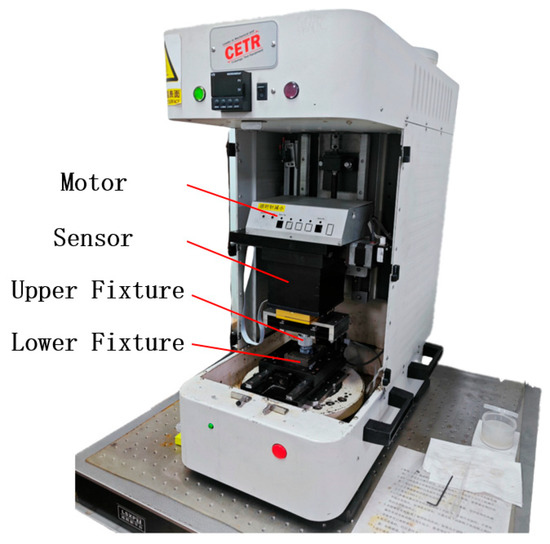
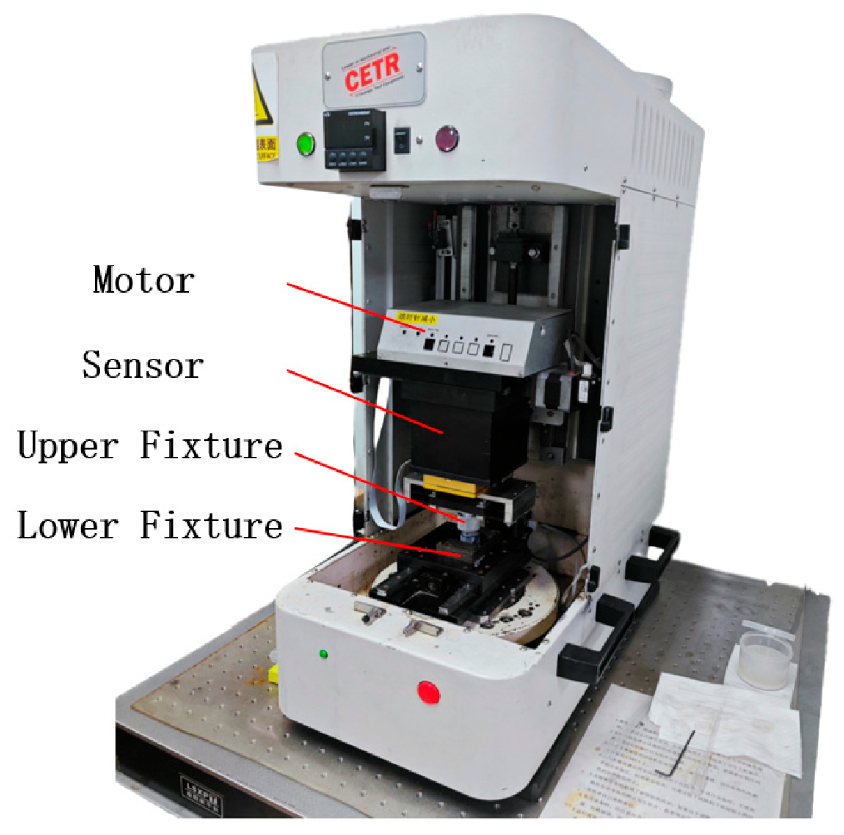
Friction coefficient measurements were performed using a CERT-UMT linear reciprocating tribometer, as shown in Figure 1. By adjusting the stroke length and reciprocating frequency of the servo motor, the sliding velocity could be precisely controlled, thereby enabling the acquisition of friction response characteristics under different velocity conditions. The tribometer was equipped with a high-precision friction force sensor, as well as displacement and velocity monitoring modules. During the experiments, key parameters—including friction force, sliding velocity, and friction coefficient—were sampled at a preset frequency, automatically recorded, and stored in real time.
Figure 1.
Linear reciprocating tribometer.
2.2. Experimental Materials
To systematically investigate the evolution of friction characteristics at the drill string–formation interface under drilling fluid wetting conditions, an experimental sample system was constructed from three perspectives: drill string materials, rock types, and drilling fluid systems. The selection and preparation of specimens were conducted with full consideration of practical field engineering conditions to ensure the reliability and engineering relevance of the experimental results.
2.2.1. Drill String Material Specimens
A survey of drill string selection in horizontal and directional wells in Chinese oilfields indicates that G105 and S135 are currently the most widely used drill pipe grades. Therefore, G105 and S135 steels were selected as representative drill string materials, covering the typical range of engineering applications in current field drilling operations.
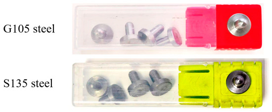
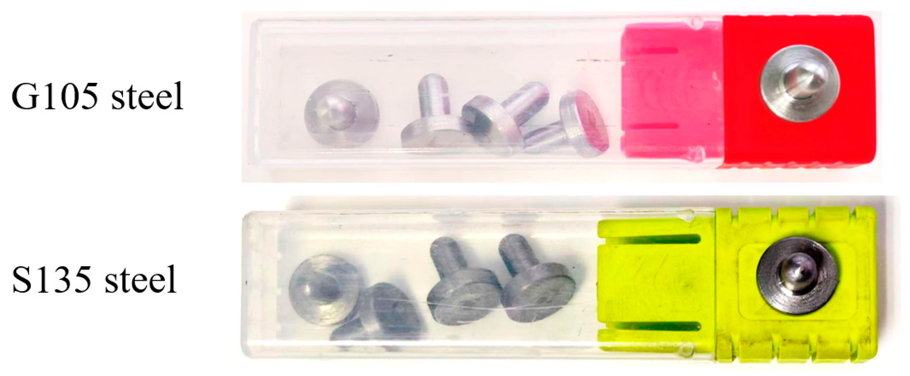
API-compliant G105 and S135 steel bars were used as the raw materials for specimen fabrication. Without altering the original metallurgical condition of the materials, the steel bars were machined into standardized specimens that satisfied the clamping and loading requirements of the friction testing apparatus. The processed specimens are shown in Figure 2.
Figure 2.
Drill String Material Specimens.
2.2.2. Rock Specimen Preparation
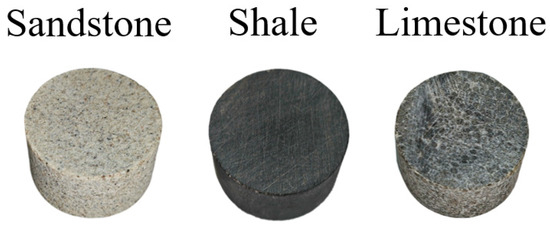
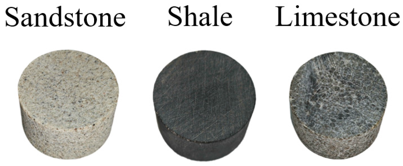
Considering the common formation types encountered during horizontal and extended-reach well drilling, sandstone, shale, and limestone were selected as representative rock types to establish an engineering-relevant rock sample system.
All rock specimens were obtained from actual oilfield cores or engineering-equivalent rock materials. During specimen preparation, low-speed cutting techniques were adopted to minimize damage to the rock microstructure and to preserve the original structural characteristics as much as possible. The rocks were subsequently processed into standardized specimens that met the installation and loading requirements of the friction testing apparatus, as shown in Figure 3.
Figure 3.
Rock Specimens.
2.2.3. Drilling Fluid Preparation and Specimen Pretreatment
As the intermediate medium at the drill string–formation interface, drilling fluid plays a critical role in determining interfacial lubrication performance and friction behavior. In this study, a representative water-based drilling fluid and a representative oil-based drilling fluid were selected as experimental fluids, corresponding to the two most used drilling fluid systems in current field operations.
Previous studies [25] have shown that under drilling fluid wetting conditions, the friction characteristics of rock surfaces vary significantly with immersion time. The friction coefficient typically decreases rapidly during the initial immersion stage and gradually stabilizes after a certain period, with stabilization generally requiring approximately 12 h.
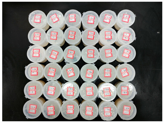
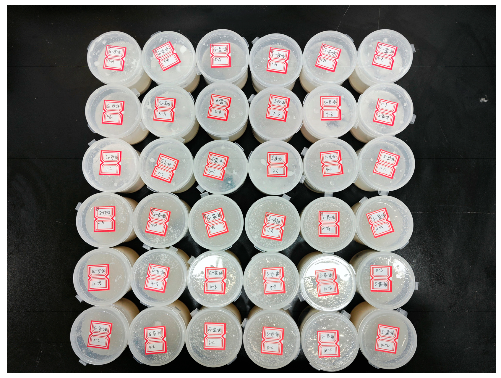
To minimize the influence of immersion time variation on friction test results and to ensure comparability among different specimens, a unified pre-immersion treatment was conducted before formal testing. Specifically, all rock specimens were immersed in their respective drilling fluids for 24 h to allow sufficient interaction between the drilling fluid and the rock surface, thereby ensuring that the interfacial lubrication state reached a stable condition. The pre-immersion process is illustrated in Figure 4.
Figure 4.
Pre-treatment of Rock Specimens for Testing.
Through the above pretreatment procedures, the interference of transient wetting effects on the friction test results was effectively eliminated, ensuring that the experimental data accurately reflect the friction characteristics of the drill string–formation interface under drilling fluid wetting conditions.
2.3. Experimental Scheme
To systematically assess how drill string material, drilling fluid system, and lithology affect the tool’s drag reduction performance, a three-factor full factorial scheme was implemented, yielding twelve distinct experimental conditions. For each test configuration, fresh specimens were mounted, and three independent repetitions were conducted to ensure the robustness and reproducibility of the measured data. In defining the test parameters, the sliding velocity range was selected to represent both the typical rate of penetration (ROP) encountered in horizontal well sections and the localized micro-slip induced by hydraulic oscillator excitation. Accordingly, velocities were prescribed from 0.1 mm/s to 6 mm/s. A staged loading protocol was adopted, in which the velocity domain was discretized into thirteen increments, with each level sustained for 3 min to guarantee measurement stability. At each velocity level, the sliding friction coefficient between the specimens was measured and recorded, thereby enabling the construction of a complete relationship curve between sliding velocity and friction coefficient for each test condition.
2.4. Experimental Results
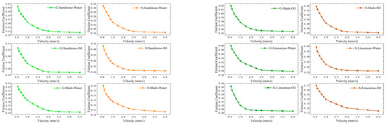
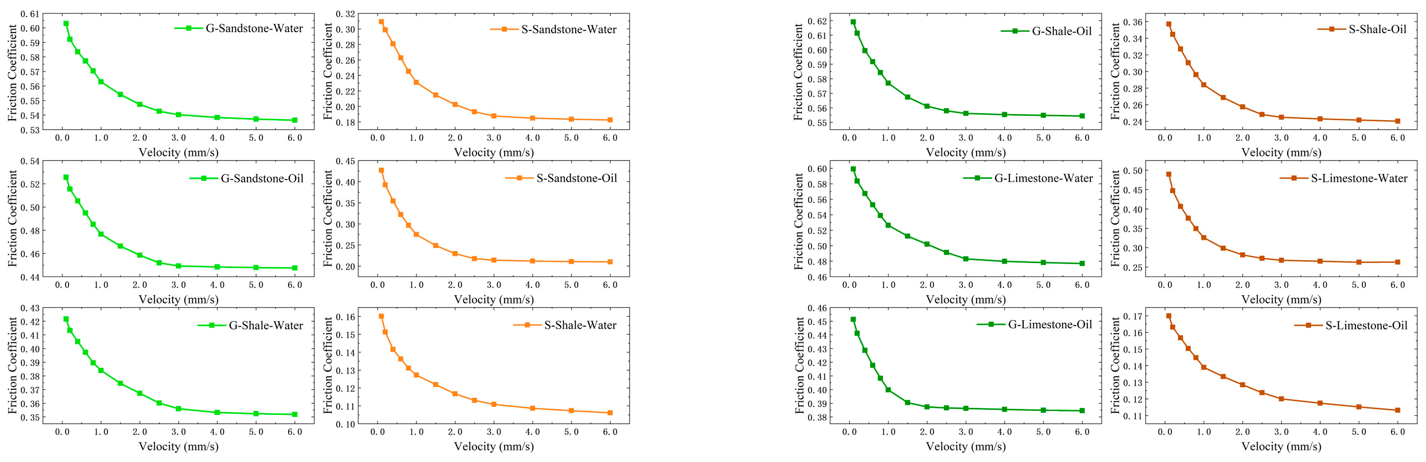
The experimental results showing the variation in the friction coefficient with sliding velocity under different test combinations are presented in Figure 5.
Figure 5.
Variation in Friction Coefficient with Sliding Velocity.
Overall, within the tested velocity range, the sliding friction coefficient exhibited a decreasing trend with increasing sliding velocity under all combinations. Although the magnitude of reduction varied among different drill string materials, rock types, and drilling fluid systems, the overall trend remained consistent across all test conditions.
3. Mechanical Model
To account for the modification of interfacial friction characteristics induced by hydraulic oscillator excitation, and based on the experimentally determined velocity-dependent friction parameters, an axial dynamic model of the drill string incorporating nonlinear friction effects was formulated. The modeling framework relies on the following idealizations:
- (1)
- The drill string is represented as a uniform, continuous elastic rod with a circular cross-section, while the borehole wall is assumed to be rigid.
- (2)
- Along the contact section, the drill string is presumed to maintain uninterrupted contact with the wellbore wall.
- (3)
- The analysis is restricted to longitudinal vibration; lateral motion, torsional dynamics, and their coupling with axial response are not considered.
- (4)
- The interaction force at the drill string–wellbore interface is characterized using the Stribeck friction formulation, enabling representation of the nonlinear dependence of friction on relative sliding velocity.
- (5)
- Under a scale-separation assumption, the hydraulic oscillator is idealized as a high-stiffness spring element that delivers a stable periodic axial excitation force. The influences of tool stroke limits, internal nonlinearities, and hydraulic inertial effects are neglected.
- (6)
- Efficient cutting transport in the wellbore is assumed. Under extreme cutting accumulation conditions, additional corrections based on particle contact mechanics would be required.
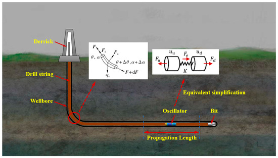
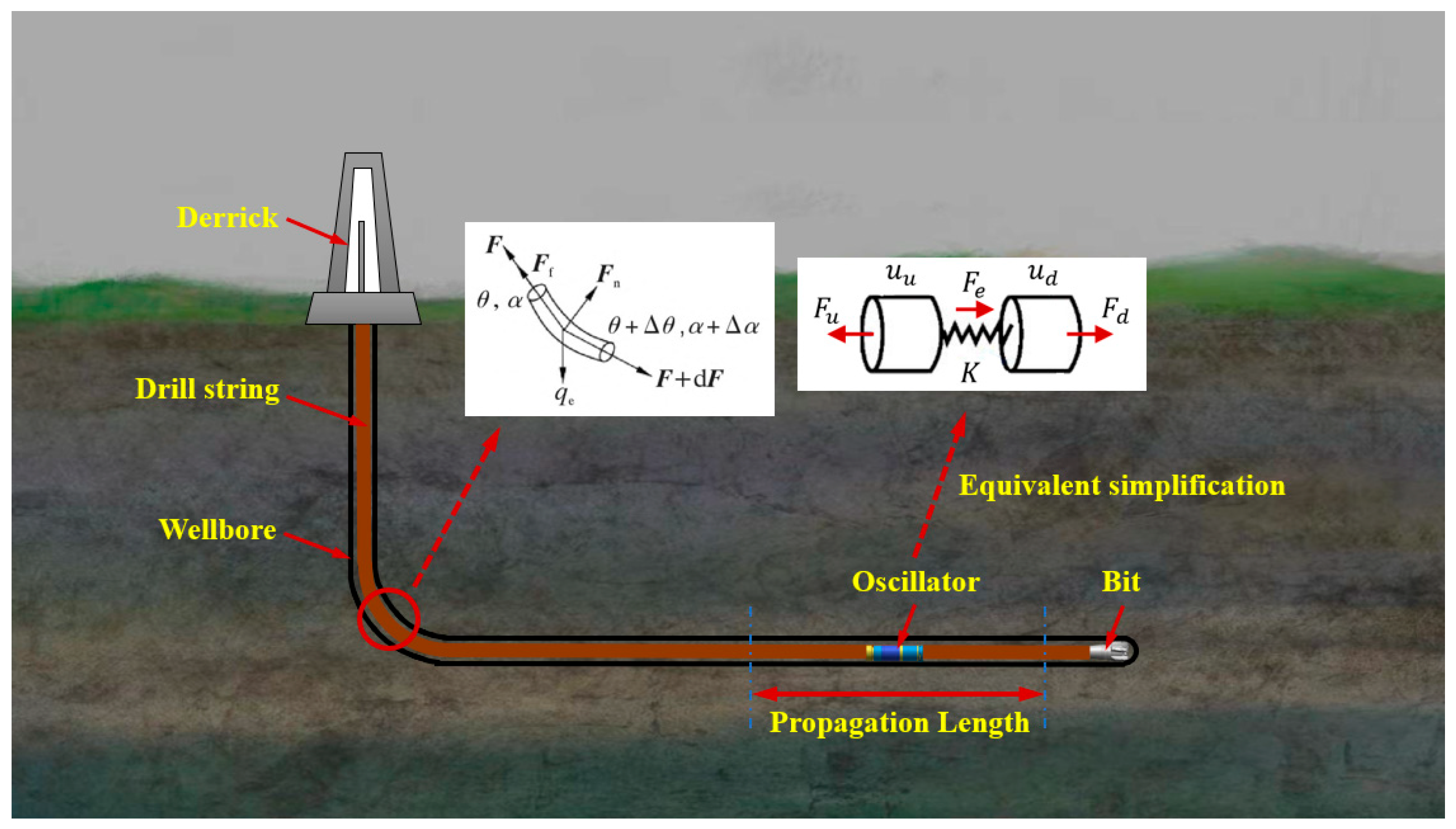
A schematic diagram of the drill string system equipped with a hydraulic oscillator is shown in Figure 6.
Figure 6.
Structural schematic of the drill string integrated with a hydraulic oscillator.
3.1. Governing Equations of the Drill String
Assuming that the drill string is initially at rest, the drill string is discretized conceptually into infinitesimal elements for force analysis. Considering the axial force balance of an arbitrary micro-element, the mechanical equilibrium equation can be derived as
Since ∂s, the above equation can be rewritten as
When the hydraulic oscillator operates, it imposes a periodic excitation force on the drill string. Under excitation, the friction force between the drill string and the wellbore wall varies dynamically. Accordingly, the axial vibration governing equation of the drill string can be expressed as
The above equation can be rewritten as
In the equation, is the Young’s modulus; is the density of the drill string; U is the axial displacement; s is the length coordinate of the drill string element; is the buoyant weight per unit length; is the wellbore inclination; is the cross-sectional area; is the diameter of the drill string; is the viscosity coefficient of the drilling fluid; is the fluid flow velocity; and is the friction force between the drill string and the borehole wall.
3.2. Friction Force Model
The nonlinear dependence of interfacial friction on relative sliding velocity at the drill string–wellbore contact is described using the Stribeck model [26]. During horizontal drilling operations, the rate of penetration typically ranges from a few meters per hour to several tens of meters per hour, corresponding to relatively low sliding velocities at the contact interface. Experimental studies have demonstrated that within this low-velocity regime, the Stribeck formulation can approximate the actual friction force with an accuracy of about 90% [27,28,29]. The mathematical form of the Stribeck friction model is given as
In the equation, is the maximum static friction force; is the Coulomb friction force; is the relative velocity; is the characteristic velocity; and is the exponential parameter.
4. Computational Method
4.1. Finite Difference Method
To numerically solve the axial dynamic governing equation of the drill string, the continuous system is discretized into a finite number of elements. A finite difference scheme combining spatial and temporal discretization is employed to construct the discrete dynamic model.
A sufficiently small time increment is introduced to ensure numerical stability and accuracy. The axial displacement of the -th spatial node at the -th time step is denoted as .
Based on the discretization definitions, the explicit central difference formulations of Equations (3) and (5) can be written as
4.2. Initial and Boundary Conditions
To obtain a well-posed solution of the drill string dynamic governing equation, appropriate initial and boundary conditions must be defined. Before activation of the hydraulic oscillator, the drill string is considered to have been fully run into the well and to remain in longitudinal static equilibrium. Under this pre-excitation state, no axial oscillation is present, and both the axial displacement and axial velocity are taken as zero. Accordingly, the initial condition is specified as
In the equation, is the initial displacement.
At the upper end, the drill string is suspended from the derrick hook. Since the axial movement at this location can be directly controlled from the surface, the displacement at the top boundary is prescribed as a known input parameter:
In the equation, is the displacement of the hook.
At the lower end, the drill string is connected to the drill bit. The interaction between the bit and the formation generates a reaction force that can be represented as an equivalent axial load acting at the bottom of the string, with magnitude equal to the negative weight on bit (WOB). Therefore, the boundary condition at the lower end is written as
In the equation, WOB is the weight on the bit.
4.3. Continuity Conditions
Based on the working mechanism of the hydraulic oscillator, it is simplified as an axial element consisting of a high-stiffness spring connected in series with a periodic excitation force, as illustrated in Figure 6.
To ensure mechanical compatibility and equilibrium at structural connection points, continuity conditions must be satisfied at the interfaces between the hydraulic oscillator and the adjacent drill string sections. Specifically, both axial displacement and axial internal force must remain continuous across the connection.
The continuity conditions are expressed as
In the equation, , are the axial force and displacement at the upper end of the oscillator; , are the axial force and displacement at the lower end; is the equivalent stiffness of the oscillator; and is the excitation force.
Furthermore, when the drill string system consists of sections with different specifications (e.g., varying diameter, cross-sectional area, or unit weight), axial force continuity must also be satisfied at the connection between adjacent sections:
The dynamic governing equations are discretized and solved through an explicit finite difference formulation, selected for its relatively high computational efficiency compared with implicit solution strategies. Because the adopted friction representation exhibits strong nonlinearity, the temporal discretization must be carefully controlled. A sufficiently small-time increment is required to preserve numerical stability and to confine truncation errors within an acceptable range.
4.4. Model Validation
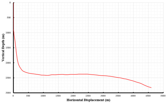
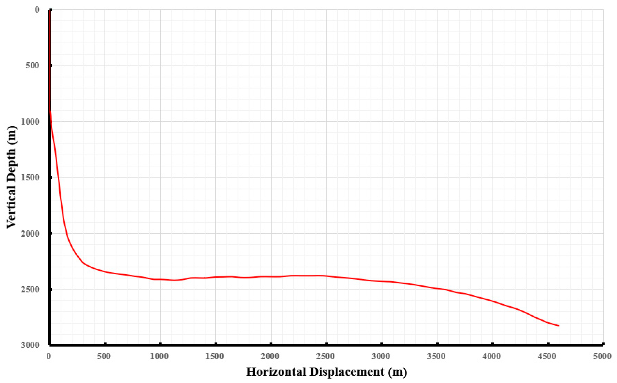
The credibility and predictive capability of the proposed drill string dynamic model were assessed through comparison with field data. For this purpose, the SY9-6HF well in Northwest China was chosen as a representative case for validation. In this well, the kickoff point (KOP) is located at a measured depth of 890 m, with an inclination angle of approximately 63°. The total measured depth (MD) is 6780 m, the true vertical depth (TVD) is 2822 m, the horizontal displacement is 4597 m, and the horizontal section length reaches 3332 m. The well trajectory exhibits typical characteristics of a long horizontal section with significant cumulative friction and drag, making it representative for model validation in extended-reach drilling conditions.
During drilling operations, a combined directional and rotary drilling mode was employed. The drill string assembly consisted of a 5 in. drill pipe, a 5 in. heavy-weight drill pipe (HWDP), and a 5½ in. drill pipe. A hydraulic oscillator was incorporated into the bottom hole assembly (BHA) and installed approximately 200 m above the drill bit. The well trajectory profile is illustrated in Figure 7.
Figure 7.
Wellbore Profile of Well SY9-6HF.
The other input parameters required for the model calculation are listed in Table 1. To ensure the stability and convergence of the numerical results, the axial dynamic equation of the drill string is solved using an explicit finite-difference scheme. For one-dimensional wave propagation problems, the stability of the explicit scheme must satisfy the Courant–Friedrichs–Lewy (CFL) stability criterion, which can be expressed as
In the equation, denotes the propagation velocity of the axial stress wave in the drill string, and represent the elastic modulus and density of the drill string material, respectively.
To satisfy the numerical stability requirement while maintaining a balance between computational accuracy and efficiency, the spatial step size and time step in this case are selected as Δx = 0.6 m and Δt = 1.25 × 10⁻⁴ s.
Table 1.
Model Calculation Parameters.
To ensure objectivity and reproducibility of comparative analysis, the commercial drilling engineering software Halliburton Landmark(version EDT 5000.14.) was adopted as a benchmark reference. Landmark is one of the most widely applied drilling and wellbore engineering analysis platforms in the global oil and gas industry. Its wellbore design and mechanical analysis modules are extensively used for horizontal and extended-reach well design, drill string force analysis, and friction and drag prediction, providing a mature engineering validation framework.
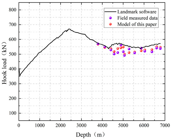
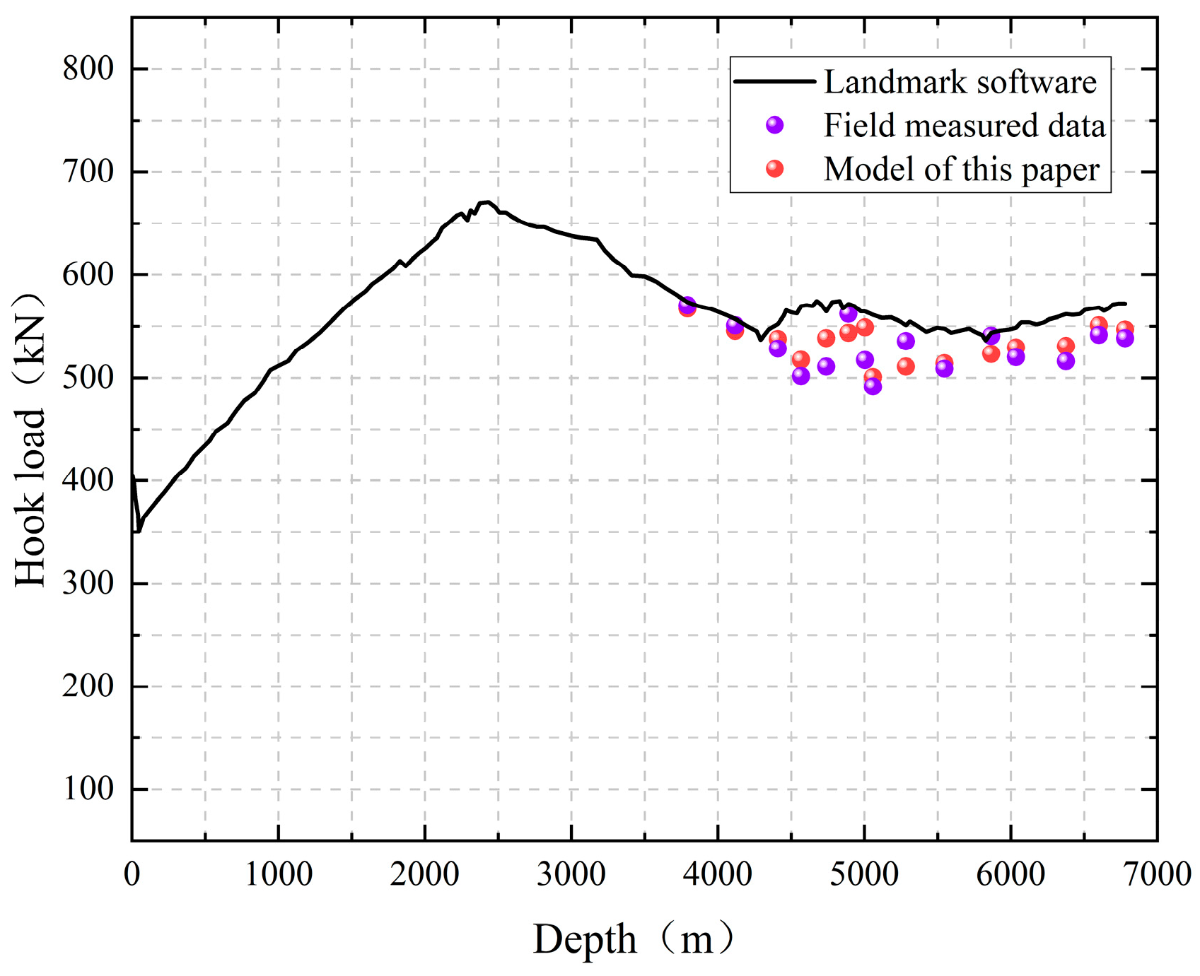
After parameter configuration for both the Landmark model and the present model, the corresponding hook load–measured depth curves were calculated and compared with field-measured hook load data. The comparison results are presented in Figure 8.
Figure 8.
Variation in Hook Load with Well Depth.
The results demonstrate that the predicted hook load trend from the present model is consistent with the field measurements over the entire well section. Quantitatively, the present model shows closer agreement with field data compared with the Landmark results. The maximum and average relative errors of the Landmark simulation are 14.2% and 6.3%, respectively, whereas those of the present model are reduced to 6.1% and 2.6%. In terms of both peak deviation and overall statistical accuracy, the proposed model exhibits superior predictive performance. The reduced error level indicates that the incorporation of velocity-dependent nonlinear friction and vibration coupling improves the fidelity of friction and drag prediction under long horizontal section conditions. Therefore, the validated model provides a reliable computational foundation for subsequent parametric investigations on the influence of excitation characteristics and formation-dependent friction properties on the friction and drag reduction performance of the hydraulic oscillator under various drilling scenarios.
5. Results and Discussion
The excitation-induced increase in weight on bit (ΔWOB) is employed as the metric to quantify drag reduction performance. In this study, ΔWOB represents the additional bit load generated under vibrational excitation relative to the non-excited condition and is defined as
where is the total number of drill string elements influenced by the vibration induced by the hydraulic oscillator; is the frictional resistance of the element before oscillator excitation; is the average frictional resistance of the element after oscillator excitation; and is the length of each element.
Through systematic numerical simulations, the influences of excitation amplitude and excitation frequency on drag reduction performance were analyzed under different drill string materials, drilling fluids, and rock types.
5.1. Influence of Excitation Parameters Under Different Drill String Materials
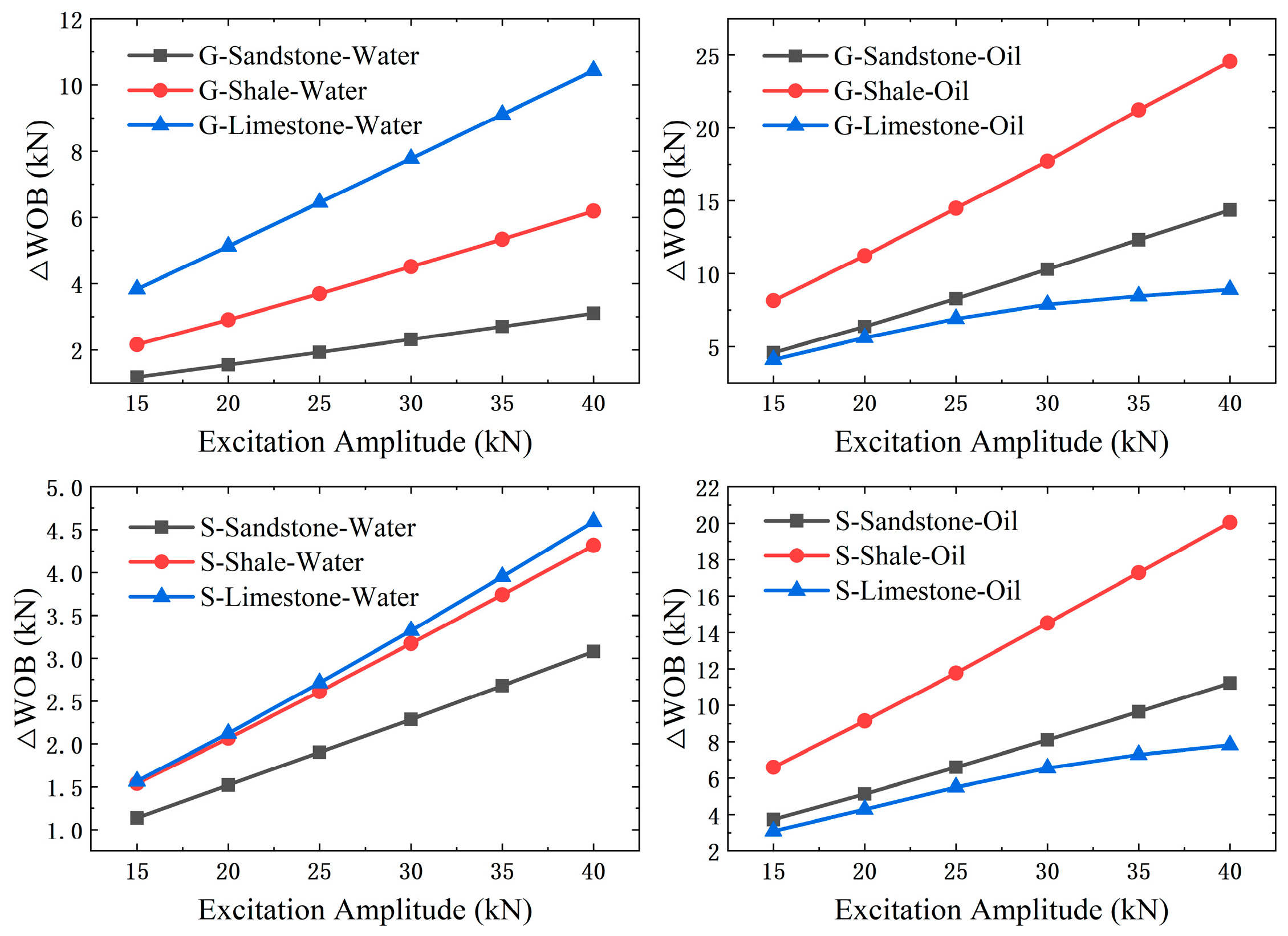
Figure 9 presents the variation in ΔWOB with excitation amplitude for different drill string materials. It can be observed that, under all parameter combinations, ΔWOB increases monotonically with increasing excitation amplitude. The growth trend exhibits a pronounced quasi-linear characteristic with a relatively large slope. This result suggests that the vibration amplitude plays a decisive role in determining the effectiveness of the hydraulic oscillator in mitigating drag, functioning as the primary governing parameter in drag reduction performance. Mechanistically, increasing amplitude directly elevates the peak axial vibration load transmitted along the drill string. As a result, the interfacial normal contact force between the drill string and the formation undergoes larger periodic fluctuations. The enhanced fluctuation amplitude promotes more effective disruption of static or quasi-static friction states and improves the axial transmission efficiency of vibrational energy. Consequently, the effective reduction in average frictional resistance becomes more significant, leading to a larger ΔWOB.
Figure 9.
Effect of Excitation Amplitude Variation under Different Drill String Materials on Tool Drag Reduction Performance.
Figure 10 illustrates the influence of excitation frequency on ΔWOB for different drill string materials.
Figure 10.
Effect of Excitation Frequency Variation under Different Drill String Materials on Tool Drag Reduction Performance.
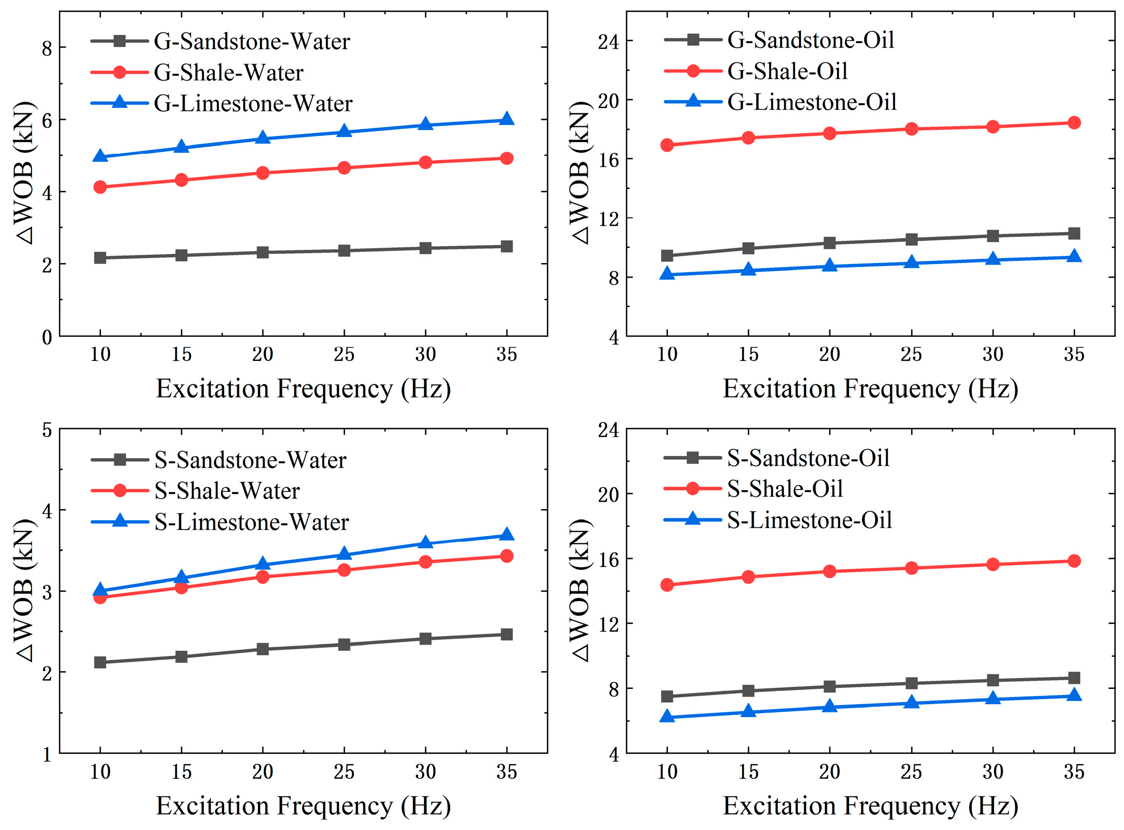
Similarly, ΔWOB increases with excitation frequency. However, the magnitude of growth is noticeably smaller than that caused by amplitude variation. This suggests that excitation frequency contributes positively to drag reduction performance, but its influence is comparatively limited.
From a physical perspective, increasing frequency primarily raises the number of vibration cycles per unit time without altering the peak load delivered in each individual cycle. Therefore, frequency enhancement mainly manifests as sustained perturbation of the interfacial dynamic friction state rather than increasing instantaneous load capacity. By shortening the friction recovery time and preventing the re-establishment of stable high-friction contact conditions, higher frequency reduces the time-averaged friction level. However, because the peak excitation force remains unchanged, the overall increment in ΔWOB grows at a relatively moderate rate.
A comparison between drill string materials shows that, under identical excitation amplitude and frequency conditions, the ΔWOB values obtained for G105 steel and S135 steel are generally close, with G105 steel exhibiting slightly higher increments.
This difference can be attributed to material-dependent interfacial friction characteristics. Compared with G105 steel, S135 steel possesses higher strength and hardness. Under the same normal load, its contact interface with rock tends to develop a larger real contact area due to reduced plastic deformation, resulting in a relatively higher baseline friction coefficient. The elevated baseline friction level increases energy dissipation at the interface and partially restricts long-distance axial propagation of vibration energy, thereby slightly weakening the drag reduction effect.
Nevertheless, the overall difference in ΔWOB between the two materials remains limited. This indicates that drill string material properties constitute a secondary influencing factor in the drag reduction performance of hydraulic oscillators, whereas excitation amplitude plays the primary controlling role.
5.2. Influence of Excitation Parameters Under Different Drilling Fluid Types
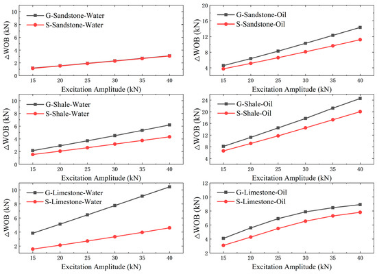
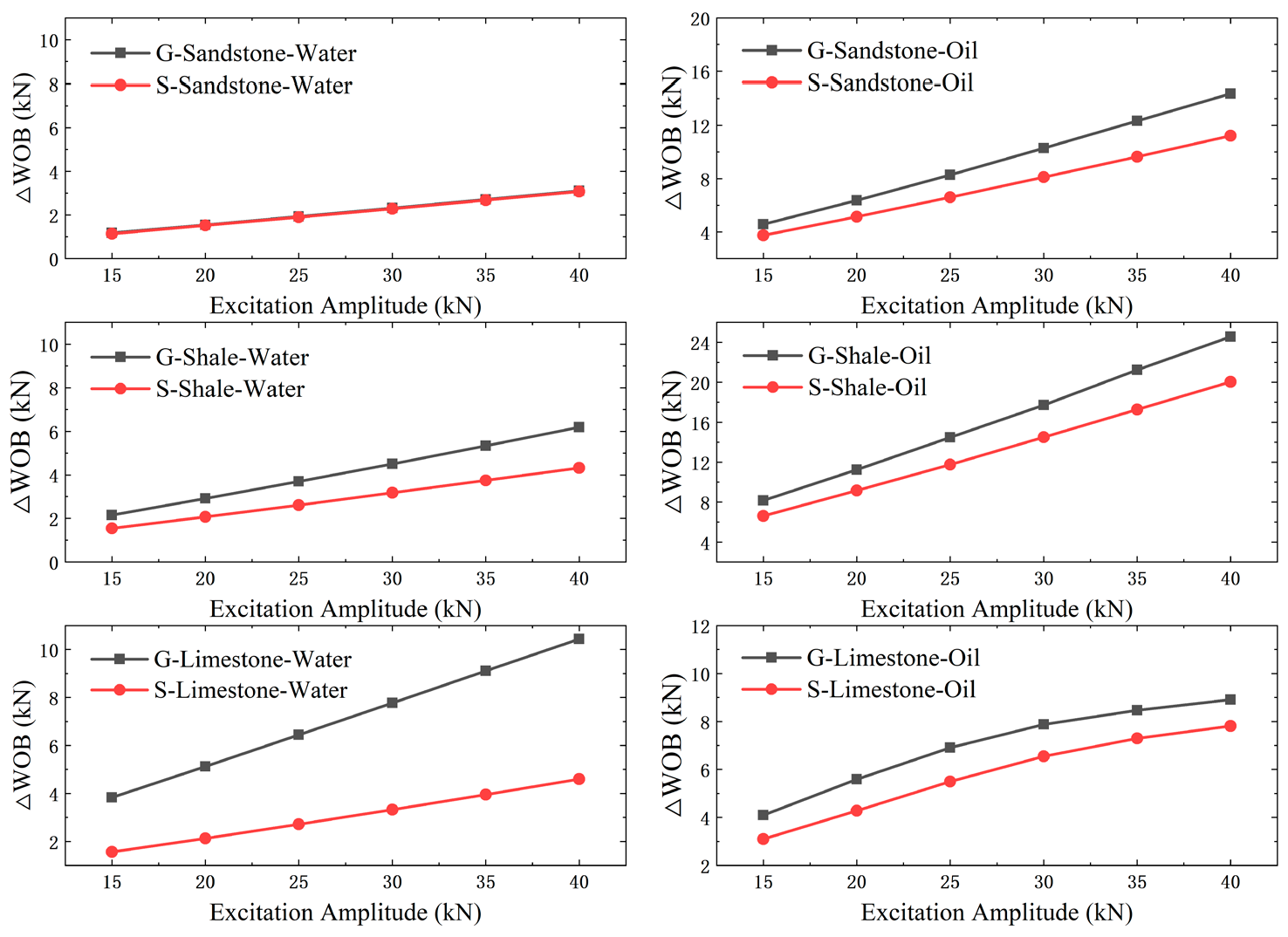
Figure 11 illustrates the variation in ΔWOB with excitation amplitude under different drilling fluid environments.
Figure 11.
Effect of Excitation Amplitude Variation under Different Drilling Fluid Types on Tool Drag Reduction Performance.
Under both water-based and oil-based drilling fluids, ΔWOB increases monotonically with increasing excitation amplitude, exhibiting an approximately linear growth trend. This confirms that excitation amplitude remains the primary control parameter for enhancing drag reduction performance.
However, significant differences are observed between lubrication environments. For all material–rock combinations, ΔWOB under oil-based drilling fluid conditions is substantially higher than that under water-based conditions, and the slope of the amplitude–ΔWOB curve is generally steeper.
This behavior can be attributed to differences in interfacial lubrication mechanisms. Oil-based drilling fluids are more capable of forming stable boundary lubrication films at the metal–rock interface. The dominant friction mechanism therefore transitions from asperity-controlled solid–solid contact to film-mediated shear. The reduced baseline friction level and enhanced velocity sensitivity allow amplitude-induced increases in oscillatory velocity to more effectively decrease time-averaged friction resistance. Consequently, the drag reduction gain per unit amplitude increment is amplified under oil-based conditions.
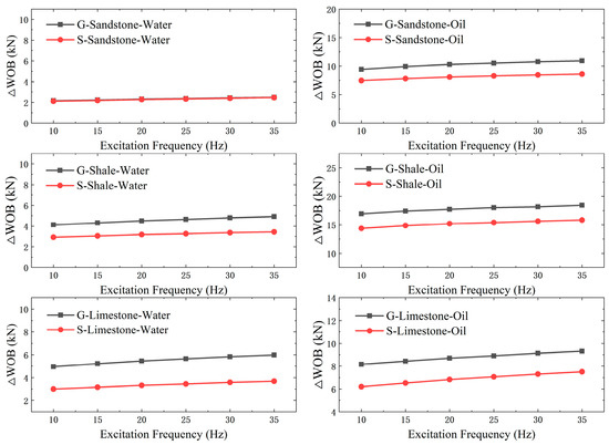
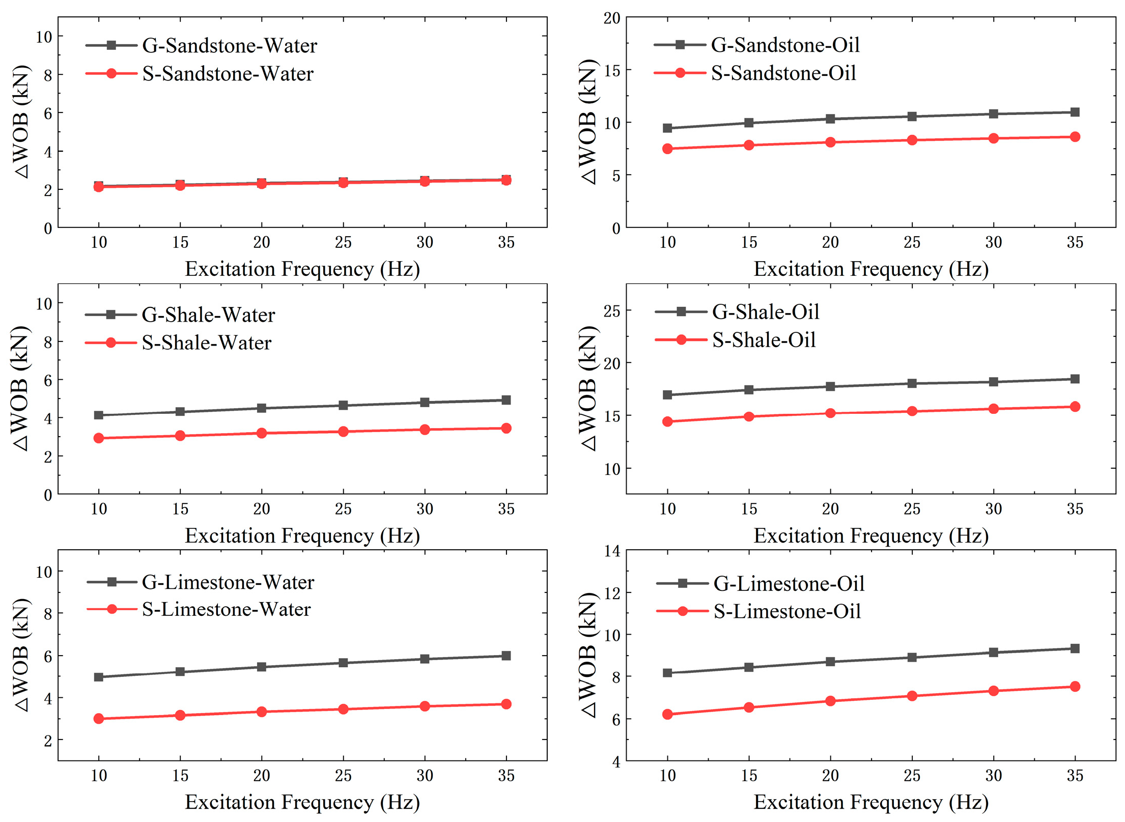
Figure 12 presents the influence of excitation frequency on ΔWOB under different drilling fluids. Although ΔWOB increases with excitation frequency, the magnitude of increase is significantly smaller than that caused by amplitude variation. The growth curves under water-based conditions are noticeably flatter. The effectiveness of frequency enhancement is strongly dependent on the lubrication state. Under oil-based drilling fluid conditions, the friction coefficients across all velocity ranges are consistently lower than those under water-based conditions due to the presence of organic lubricating components that promote stable boundary film formation. In contrast, water-based fluids form less stable lubrication layers, and friction remains more strongly governed by direct asperity interaction.
Figure 12.
Effect of Excitation Frequency Variation under Different Drilling Fluid Types on Tool Drag Reduction Performance.
Overall, drilling fluid type is a dominant environmental factor influencing hydraulic oscillator performance. Under oil-based conditions, drag reduction performance is stronger and more responsive to both amplitude and frequency adjustment. Under water-based conditions, drag reduction improvement relies primarily on amplitude enhancement, while frequency mainly provides limited fine-tuning of interfacial friction dynamics.
5.3. Influence of Excitation Parameters Under Different Rock Types
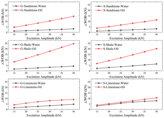
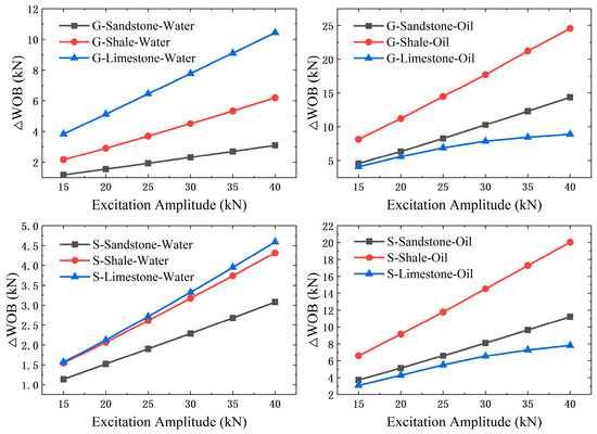
Figure 13 shows the variation in ΔWOB with excitation amplitude under sandstone, shale, and limestone formations. In all lithologies, ΔWOB increases significantly with increasing excitation amplitude and exhibits an approximately linear growth trend. However, the slopes of the curves differ markedly among rock types. Under water-based drilling fluid conditions, the ranking of ΔWOB is limestone > shale > sandstone; under oil-based drilling fluid conditions, the ranking becomes shale > sandstone > limestone. Thus, the relative performance between sandstone and limestone reverses depending on the lubrication environment.
Figure 13.
Effect of Excitation Amplitude Variation under Different Rock Types on Tool Drag Reduction Performance.
The underlying reason for this phenomenon lies in the transition of the interfacial lubrication mechanism. In water-based drilling fluid environments, the lubrication capability at the interface is limited, and the contact condition is closer to a regime dominated by direct asperity contact or abrasive interactions. Under such conditions, sandstone, characterized by high surface roughness and a pronounced granular structure, exhibits stronger interfacial energy dissipation. As a result, vibration propagating along the drill string attenuates more rapidly, thereby limiting the drag-reduction benefit. In contrast, limestone generally possesses a relatively dense surface structure and a lower interfacial friction level, which leads to a more pronounced drag-reduction performance. In oil-based drilling fluid environments, the lubricating oil film further suppresses direct asperity contact, causing the interfacial friction regime to transition from rough-contact-dominated behavior to a boundary-lubrication or weak adhesion–slip controlled state. Under these conditions, the interfacial friction characteristics of sandstone are significantly improved, the attenuation of vibration energy is reduced, and the drag-reduction gain resulting from increased excitation amplitude becomes substantially more pronounced.
Under limestone–oil-based conditions, where baseline lubrication is already favorable, and friction levels are relatively low, the growth rate of ΔWOB gradually flattens with increasing amplitude, exhibiting marginal diminishing returns. This indicates that when the interfacial friction level is already reduced, further amplitude increase alone provides limited additional drag reduction potential. Therefore, the contribution of amplitude is strongly dependent on lithology and the lubrication regime.
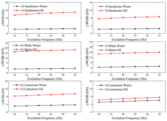
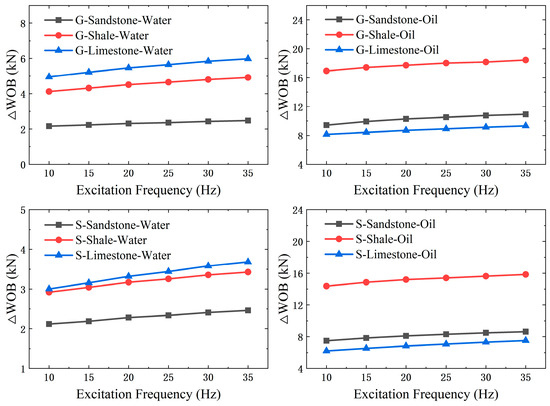
Figure 14 illustrates the effect of excitation frequency under different rock types. Overall, ΔWOB increases with excitation frequency, but the magnitude remains smaller than that associated with amplitude variation. In certain friction regimes, however, the marginal benefit of frequency enhancement becomes more pronounced.
Figure 14.
Effect of Excitation Frequency Variation under Different Rock Types on Tool Drag Reduction Performance.
For example, under water-based fluid with limestone and oil-based fluid with shale, ΔWOB increases steadily with frequency and exhibits a relatively larger proportional gain compared to other combinations. In these cases, the interfacial friction state is likely governed by boundary lubrication or weak adhesion–sliding mechanisms. Increasing excitation frequency raises the number of dynamic perturbations per unit time, suppresses re-establishment of stable high-friction contact states, and continuously reduces the effective dynamic friction level. When amplitude-induced gains become limited, frequency adjustment provides an additional mechanism for drag reduction.
Overall, formation lithology plays a decisive role in determining the drag reduction performance attainable through excitation parameter enhancement. The effectiveness of amplitude increases exhibits pronounced lithology dependence, whereas frequency adjustment provides additional drag reduction potential under specific formation–lubrication regimes. Accordingly, excitation parameter design for hydraulic oscillators should not adopt a uniform or generalized configuration. Instead, a formation-adaptive design framework should be established that explicitly integrates drilling conditions and interfacial friction characteristics, with coordinated consideration of drill string material grade, drilling fluid type, and formation lithology, thereby enabling optimized drag reduction performance under varying operational environments.
6. Design Method for Hydraulic Oscillator Excitation Parameters Matching Drilling Conditions and Formation Characteristics
The drag-reduction performance of hydraulic oscillators is jointly determined by the interaction between excitation parameters and the friction environment. Therefore, the design of tool excitation parameters should be conducted in accordance with drilling fluid type, formation lithology, and interfacial friction conditions. Based on this understanding, a design methodology for excitation parameters that match formation characteristics and drilling conditions is established to guide the rational selection and parameter configuration of hydraulic oscillators, and the design principles of this methodology are first clarified as follows:
- (1)
- Excitation amplitude is the dominant parameter governing drag reduction capability.
- (2)
- Excitation frequency plays a supplementary role, but its effectiveness exhibits pronounced dependence on operational conditions.
- (3)
- Sensitivity of drag reduction to amplitude and frequency is highly dependent on lithology and drilling fluid conditions.
Therefore, excitation parameter design should be fundamentally based on friction mechanisms rather than fixed empirical parameter settings.
In high-friction, boundary-lubrication-dominated conditions—such as sandstone formations or water-based drilling fluid environments—interfacial lubrication primarily occurs via boundary or mixed lubrication. The baseline friction level at the interface is elevated, and pronounced “stick-slip” behavior frequently occurs.
In such conditions, increasing excitation amplifies friction fluctuations, thereby enhancing the probability of overcoming static friction thresholds. Drag reduction gains lithological sensitivity, with limestone and shale demonstrating stronger responses to amplitude enhancement than sandstone. The marginal benefits of increasing excitation frequency are limited and should be controlled within a moderate range to avoid excessive vibration and energy dissipation. Therefore, in high-friction environments, amplitude enhancement should be prioritized, with frequency primarily used for supplementary optimization.
In low-friction, lubricant film-dominated conditions—such as limestone formations or oil-based drilling fluid environments, the formation of a stable lubricant film shifts the dominant friction mechanism from solid contact to lubricant film shear. This reduces the baseline friction level and increases sensitivity to velocity perturbations.
In such conditions, amplitude remains important; however, diminishing returns may occur in certain lithologies (e.g., limestone). Under specific combinations, such as shale with oil-based fluids or limestone with water-based fluids, increasing excitation frequency can yield additional drag reduction benefits. Therefore, synergistic optimization of amplitude and frequency is required rather than solely increasing amplitude.
Based on the above analysis, a hydraulic oscillator excitation parameter design method tailored to drilling conditions and formation characteristics is proposed:
- (1)
- Condition identification: Determine drilling fluid type, hydraulic conditions, and primary lithological characteristics of the target well section to assess the interfacial lubrication state and friction level.
- (2)
- Primary control parameter determination: Select excitation amplitude or excitation frequency as the primary control direction based on the friction environment, with excitation amplitude always prioritized as the primary design parameter.
- (3)
- Parameter co-optimization: Coordinate excitation amplitude and frequency under the constraints of tool structural strength and downhole energy consumption.
- (4)
- Dynamic adjustment and validation: Adjust tool excitation parameters based on field friction variations and drilling pressure responses to ensure stable drag reduction performance.
In summary, the rational design of hydraulic oscillator excitation parameters should center on interfacial friction characteristics. By differentiating drilling fluid environments and formation lithology conditions, a parameter matching approach characterized by “amplitude as primary control, frequency as auxiliary, and adaptation to specific conditions” is established. This design methodology enables the full realization of the vibration-induced drag reduction potential of hydraulic oscillators under specific drilling block conditions and provides theoretical foundations and engineering guidance for their adaptive design and efficient application in complex formations and extended horizontal drilling operations.
7. Conclusions
- (1)
- Based on experimental data, a drill string dynamic model incorporating nonlinear friction was established, providing a reliable parameter foundation and theoretical support for the quantitative evaluation of hydraulic oscillator drag reduction performance.
- (2)
- The impact of drill string material differences on tool drag reduction capability is quite limited. Under identical excitation conditions, G105 steel achieved a slightly higher increase in weight on bit than S135 steel. The difference between the two materials does not alter the overall trend of excitation parameter changes and has a minor influence, making it a secondary factor.
- (3)
- Drilling fluid type is the dominant environmental factor affecting drag reduction performance. Oil-based drilling fluids significantly reduce the baseline interfacial friction level by forming a stable lubricating film, resulting in substantially superior overall drag reduction performance compared with water-based conditions and greater sensitivity to variations in excitation parameters.
- (4)
- The effectiveness of drag reduction is notably affected by the type of rock involved; lithology influences tool drag reduction performance by altering interfacial friction characteristics and vibration energy attenuation behavior. When using water-based drilling fluid, drag reduction performance is generally highest in limestone, followed by shale, and lowest in sandstone. In contrast, under oil-based drilling fluid conditions, shale demonstrates the best drag reduction results, ahead of sandstone, with limestone showing the least improvement.
- (5)
- Excitation amplitude is the primary control parameter for enhancing the drag-reduction capability of the hydraulic oscillator, and its improvement effect is significantly greater than that of excitation frequency under most operating conditions. In engineering applications, increasing excitation amplitude should therefore be prioritized to improve drag-reduction efficiency. However, under drilling conditions characterized by relatively low friction levels, such as limestone with water-based drilling fluid or shale with oil-based drilling fluid, when the excitation amplitude is constrained by factors including tool structural strength, pump pressure, or flow rate, increasing the excitation frequency can provide additional drag-reduction benefits.
- (6)
- A hydraulic oscillator excitation parameter design method that matches drilling conditions and formation characteristics is proposed. The method adopts excitation amplitude as the primary control parameter and excitation frequency as the auxiliary regulatory parameter and performs targeted optimization by integrating drilling parameters and formation parameters. This approach provides a theoretical basis for the rational selection and parameter configuration of hydraulic oscillators in complex formations and extended horizontal well sections.
It should be noted that the drill string dynamic model established in this study is based on the assumption of a continuous and homogeneous elastic rod and focuses on the mechanism dominated by axial vibration, without explicitly coupling torsional and radial vibration effects. The experimentally obtained relationship between friction coefficient and sliding velocity at the interface is embedded into the dynamic equations as a constitutive parameter, and the macroscopic mechanical response is predicted through spatial integration of the drill string elements along the wellbore section. Therefore, the conclusions of this study are applicable to the analysis of long horizontal well sections where axial vibration modulating interfacial friction is the primary drag-reduction mechanism. For special operating conditions involving significant axial–torsional coupled vibration, strong lateral impacts, or complex wellbore contact states, further investigation is still required within a multi-degree-of-freedom coupled modeling framework.
Author Contributions
Conceptualization, X.H.; methodology, X.H.; software, X.H.; validation, X.H. and T.C.; formal analysis, X.H.; investigation, W.W., L.W., and S.L.; resources, X.H.; data curation, X.H.; writing—original draft preparation, X.H.; writing—review and editing, X.H.; visualization, X.H.; supervision, X.H.; project administration, G.L. and J.L.; funding acquisition, G.L. and J.L. All authors have read and agreed to the published version of the manuscript.
Funding
This paper was supported by the project Intelligent Magnetic Guidance and Dynamic Risk Prevention for Large Platforms (2025ZD1404602), the project Unconventional Intelligent Drilling and Intelligent Equipment for Continuous Operation in Ultra-Deep Wells (2025ZD1404600), and the PetroChina–China University of Petroleum (Beijing) Strategic Cooperation Project (ZLZX2020-01).
Data Availability Statement
The original contributions presented in this study are included in the article. Further inquiries can be directed to the corresponding author(s).
Conflicts of Interest
The authors declare no conflict of interest.
References
- Zheng, M.; Li, J.; Wu, X.; Wang, S.; Guo, Q.; Chen, X.; Yu, J. Hydrocarbon resource potential of major petroliferous basins in China and future key exploration fields. Earth Sci. 2019, 44, 833–847. [Google Scholar]
- Sun, Y.; Jia, L. Drilling practice and understanding of 3000 m long horizontal section wells in China. Pet. Drill. Prod. Technol. 2020, 42, 393–401. [Google Scholar]
- Han, C.; Yan, T. Study on stick–slip behavior of drill string in extended reach wells. Nat. Gas Ind. 2004, 24, 58–60. [Google Scholar]
- Li, Z.; Yang, H.; Xu, C.; Chen, X.; Liu, X. Principle and technology of sliding drilling feed in directional wells. Nat. Gas Ind. 2013, 33, 94–98. [Google Scholar]
- Chang, W.; Yi, X.; Wan, J.; Wei, S.; Jang, S. Application of mechanical vibration drag reduction technology in sliding drilling. Mech. Eng. 2015, 3, 146–148. [Google Scholar]
- Niu, S. Application of hydraulic oscillation plugging removal technology. Oil Field Equip. 2002, 31, 38–40. [Google Scholar]
- Liu, Z.; Li, R. Application of φ172 mm hydraulic oscillator in shallow and middle-depth horizontal wells in western Sichuan. Nat. Gas Technol. Econ. 2012, 6, 37–39. [Google Scholar]
- Rasheed, W. Extending the reach and capability of non-rotating BHAs by reducing axial friction. In Proceedings of the SPE/ICoTA Coiled Tubing Roundtable, Houston, TX, USA, 7–8 March 2001. SPE-68505. [Google Scholar]
- McCarthy, J.P.; Stanes, B.H.; Clark, K.W.; Kollker, C.R.; Leuenberger, G.E.; Rebellon, J.; Grabski, L.E. A step change in drilling efficiency: Quantifying the effects of adding an axial oscillation tool within challenging wellbore environments. In Proceedings of the SPE/IADC Drilling Conference and Exhibition, Amsterdam, The Netherlands, 17–19 March 2009. SPE-119958. [Google Scholar]
- Wang, W.; Liu, G.; Li, J.; Zha, C.; Chen, T. Structural design and performance parameters of valve-type hydraulic oscillator. China Pet. Mach. 2022, 50, 17–23. [Google Scholar]
- Liu, H. Theoretical Analysis and Experimental Study of Jet Hydraulic Oscillator. Ph.D. Thesis, Jilin University, Changchun, China, 2014. [Google Scholar]
- Baker, H.D.; Cook, W.; Fuller, D.D. Proceedings of the First U.S. National Congress of Applied Mechanics Held at Illinois Institute of Technology, Chicago, IL, USA, 11–16 June 1951; American Society of Mechanical Engineers: New York, NY, USA, 1952. [Google Scholar]
- Pohlman, R.; Lehfeldt, E. Influence of ultrasonic vibration on metallic friction. Ultrasonics 1966, 4, 178–185. [Google Scholar] [CrossRef] [Scilit]
- Pance, R.; Hassan, A. A study of the buckling of rotary drilling strings. AIAA J. 1971, 9, 1385–1390. [Google Scholar]
- Barakat, E.R.; Miska, S.; Yu, M.; Takach, N. The effect of hydraulic vibrations on initiation of buckling and axial force transfer for helically buckled pipes at simulated horizontal wellbore conditions. In Proceedings of the SPE/IADC Drilling Conference, Amsterdam, The Netherlands, 20–22 February 2007. SPE-105123-MS. [Google Scholar]
- Wicks, N.; Pabon, J.; Zheng, A. Modeling and field trials of the effective tractoring force of axial vibration tools. In Proceedings of the SPE Deepwater Drilling and Completions Conference, Galveston, TX, USA, 10–11 September 2014. SPE D021S014R004. [Google Scholar]
- Liu, Y.; Chen, P.; Wang, X.; Ma, T. Modeling friction-reducing performance of an axial oscillation tool using dynamic friction model. J. Nat. Gas Sci. Eng. 2016, 33, 397–404. [Google Scholar] [CrossRef] [Scilit]
- Zhang, W.; Shi, H.; Li, G.; Song, X.; Zhao, H. Mechanism analysis of friction reduction in coiled tubing drilling with axial vibratory tool. J. Pet. Sci. Eng. 2019, 175, 324–337. [Google Scholar] [CrossRef] [Scilit]
- Zheng, X.; Agarwal, V.; Liu, X.; Balachandran, B. Nonlinear instabilities and control of drill-string stick-slip vibrations with consideration of state-dependent delay. J. Sound Vib. 2020, 473, 115235. [Google Scholar] [CrossRef] [Scilit]
- Shi, X.; Huang, W.; Gao, D. Mechanical models of drillstrings with drag reduction oscillators and optimal design methods of vibration parameters in horizontal drilling. Geoenergy Sci. Eng. 2023, 224, 211585. [Google Scholar] [CrossRef] [Scilit]
- Shi, X.; Huang, W.; Gao, D.; Zhu, N. Optimal design of drag reduction oscillators by considering drillstring fatigue and hydraulic loss in sliding drilling. J. Pet. Sci. Eng. 2022, 208, 109572. [Google Scholar] [CrossRef] [Scilit]
- Shi, X.; Huang, W.-J.; Gao, D.-L. Mechanical behavior of drillstring with drag reduction oscillators and its effects on sliding drilling limits. J. Pet. Sci. 2021, 18, 1689–1697. [Google Scholar] [CrossRef] [Scilit]
- Landar, S.; Velychkovych, A.; Ropyak, L.; Andrusyak, A. A method for applying the use of a smart 4 controller for the assessment of drill string bottom-part vibrations and shock loads. J. Vibration. 2024, 7, 802–828. [Google Scholar] [CrossRef] [Scilit]
- Landar, S.; Velychkovych, A.; Vytvytskyi, V.; Ropyak, L. Threshold vibration metrics of drilling tools as indicators of bit wear and rate of penetration decline: Field trials and data interpretation. J. Min. Miner. Depos. 2025, 19, 147–157. [Google Scholar] [CrossRef] [Scilit]
- Liu, P. Research on Casing Deformation Evolution Law and Control Method in Shale Gas Well. Ph.D. Thesis, China University of Petroleum (Beijing), Beijing, China, 2023. [Google Scholar]
- Li, C.; Pavelescu, D. The friction-speed relation and its influence on the critical velocity of stick-slip motion. Wear 1982, 82, 277–289. [Google Scholar]
- Armstrong, B. Friction: Experimental determination, modeling and compensation. In Proceedings of the 1988 IEEE International Conference on Robotics and Automation, Philadelphia, PA, USA, 24–29 April 1988. [Google Scholar]
- Canudas de Wit, C.; Carrillo, J. A modified EW-RLS algorithm for systems with bounded disturbances. Automatica 1990, 26, 599–606. [Google Scholar] [CrossRef] [Scilit]
- Ge, S.S.; Hang, L.T.; Ren, S.X. Adaptive friction compensation of servo mechanisms. Int. J. Syst. Sci. 2001, 32, 523–532. [Google Scholar] [CrossRef]
Disclaimer/Publisher’s Note: The statements, opinions and data contained in all publications are solely those of the individual author(s) and contributor(s) and not of MDPI and/or the editor(s). MDPI and/or the editor(s) disclaim responsibility for any injury to people or property resulting from any ideas, methods, instructions or products referred to in the content. |
© 2026 by the authors. Licensee MDPI, Basel, Switzerland. This article is an open access article distributed under the terms and conditions of the Creative Commons Attribution (CC BY) license.