


Abstract
Sub-synchronous oscillation problems may be induced when direct-drive wind turbines are connected to a weak AC power grid, and then it is necessary to analyze the mechanism of sub-synchronous oscillation and study effective suppression methods. In this paper, the disturbance of direct-drive wind turbines connected to the grid is analyzed firstly. The result indicates that the regulation ability of traditional current inner-loop PI controller is limited and may even exacerbate oscillation. Then a new current inner-loop controller is designed which is based on linear active disturbance rejection control. To address the difficulty in tuning the parameters of the disturbance rejection controller, the particle swarm optimization algorithm is applied. Finally, a simulation model of a direct-drive wind turbine grid connected to the power grid is built and simulated. The results show that, compared with the bandwidth method for tuning controller parameters, the particle swarm optimization algorithm has stronger adaptability to various operating conditions; the proposed linear active disturbance rejection controller based on particle swarm optimization can block the propagation of sub-synchronous frequency disturbance components strongly compared to traditional control, and the sub-synchronous oscillations are suppressed effectively.
1. Introduction
While integrating renewable energy generation into power grids reduces carbon emissions, it also introduces new challenges. Among these, sub-synchronous oscillation (SSO) has emerged as a particularly serious issue. In recent years, SSO incidents have frequently occurred worldwide, leading to large-scale wind turbine tripping and severe impacts on power system stability [1,2,3]. As a mainstream wind turbine technology, direct-drive permanent-magnet synchronous generators have matured significantly. Thus, studying SSO caused by permanent-magnet synchronous generators is crucial for ensuring the secure and stable operation of power systems.
Extensive research has been conducted on the phenomenon of SSO. Refs. [4,5] studied the SSO induced by interactions between wind farms and power grids. Study [6] attributed the tripping of doubly-fed induction generators in the case of weak grids to series-compensated transmission lines and converter control strategies. It was found that the series compensation input of transmission lines and the control strategy of inverters were sensitive to low-frequency oscillations, leading to the occurrence of sub-synchronous oscillations. A damping-enhanced filter in grid-side converters was proposed to mitigate oscillations. Refs. [7,8] suggest that due to the interaction between wind farm inverters and the power grid itself, SSO faults may occur during the parallel connection of direct-drive wind farms and weak AC power grids. Ref. [9] derived the dynamic model and input admittance model of a direct-drive fan based on a synchronous reference coordinate system. It is believed that the negative conductivity characteristic of the input admittance on the grid side of the direct-drive fan in the sub-synchronous frequency range is an important manifestation of sub-synchronous oscillation. Ref. [10] analyzed the response process of grid-side converters to grid harmonics and found that when the phase between the input and output harmonics of the converter satisfies a certain relationship, sub-/super-synchronous oscillations will occur at a certain frequency due to positive feedback, and the oscillation intensity and frequency are related to multiple factors such as the proportional and integral coefficients of the phase-locked loop, the proportional coefficient of the current inner loop, and the grid strength. Ref. [11] conducted a detailed screening of the mechanism of mode resonance induced sub-synchronous oscillation instability in direct-drive wind turbines from the perspective of the safety domain of phase-locked loop parameters, and analyzed the influence of system parameters and control parameters on the sub-synchronous oscillation characteristics of wind power grid connection.
Traditional PI control on the network side is difficult to work under SSO conditions and may even cause further oscillation. Active disturbance rejection control (ADRC) is a control method developed by researcher Han Jingqing of the Chinese Academy of Sciences based on modern control theory and improved by the PI control method. It is independent of the controlled object and can estimate and compensate for sub-synchronous disturbances and external disturbances without relying on other external accuracy models [12]. ADRC has good robustness and strong anti-interference ability, and has a good suppression effect on uncertain large disturbances. Refs. [13,14] propose using an ADRC controller instead of traditional current inner-loop PI control, and the results show that it has a certain suppression effect on SSO, but its parameter adjustment is difficult. Ref. [15] adopts a first-order linear ADRC strategy to suppress SSO, and the analysis shows that the designed controller has a strong suppression effect on the sub-synchronous frequency disturbance component. According to the concept of complex torque coefficient in reference [16], a multi-channel second-order ADRC static reactive power generator is designed to make the electrical damping coefficient positive, thereby suppressing the sub-synchronous oscillation of the wind farm. Refs. [17,18] proposed using an improved ADRC to suppress sub-synchronous oscillations, but the parameter tuning effect was unsatisfactory using traditional bandwidth methods.
This research focuses on the SSO problem of direct-drive wind turbine grid connected systems. A first-order linear active disturbance rejection controller (Linear ADRC, LADRC) is designed for suppression, and the particle swarm optimization (PSO) algorithm is used to optimize the parameters of LADRC. The results indicate that the designed PSO-LADRC can cut off the SSO propagation path and achieve the suppression of SSO.
While previous studies [13,14,15,17,18] have demonstrated the potential of ADRC/LADRC for SSO mitigation, their parameter tuning predominantly relies on the bandwidth method [19,20], which often leads to suboptimal performance under varying grid conditions. Moreover, the application of metaheuristic optimization, specifically particle swarm optimization, to systematically tune LADRC parameters for SSO suppression in direct-drive wind farms has not been comprehensively investigated. This paper aims to fill this gap by proposing a PSO-optimized LADRC and systematically evaluating its adaptability under weak to extremely weak grid conditions.
2. Materials and Methods
For a first-order system, the controlled plant is expressed as:
where represents total disturbances (internal f and external F), and denote system input and output, and is the compensation factor.
We introduce state variables and ; let ; ; ; then Equation (1) is transformed into state-space form:
When the LADRC controller suppresses disturbances, real-time estimation and compensation of disturbances are the most critical aspects. LESO (Linear Extended State Observer) is a key component here. By utilizing the input to the controlled object and the output of its own system, LESO achieves the goal of tracking state information, estimates the disturbances existing within the system, and thereby enables compensation.
LESO is given by the following equation:
where and are the tracking and total disturbance signals, and and are the gains coefficients of LESO, which are related to the system parameters.
When the first-order LADRC controller is applied, it outputs only tracking-related signals and omits differential signal processing, so the tracking differentiator can be omitted, and the input signal is directly differenced with the signal from LESO.
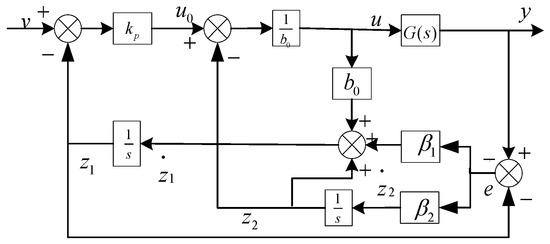
The block diagram of the LADRC control system, whose parameters are generally tuned by the bandwidth method, is shown in Figure 1. For first-order LADRC, the controller parameters obtained by the bandwidth method are ; ; [19]. Generally, the observer bandwidth ω0 can be set to 3–5 times ωc [20].
Figure 1.
LADRC control diagram.
The main components of this control structure are as follows:
Linear Extended State Observer (LESO): This is the core of the LADRC. It takes the control signal (u) and the measured output (grid current) as inputs. Its function is to estimate both the system’s internal states (z1) and the total disturbance (z2) in real time.
PD Controller: This component generates an initial control law based on the error between the reference current (iref) and the estimated current state (z1) from the LESO.
Disturbance Rejection and Compensation: The total disturbance (z2) estimated by the LESO is used to dynamically cancel out the real disturbances affecting the system. The final control signal sent to the converter (u) is the combination of the PD controller output and this compensation term.
The dynamic interaction between inverters and power grids is an important reason for the occurrence of the SSO phenomenon. Based on this, the machine-side view was considered as a controlled current source during the research process [21,22]. For grid-side inverters, without considering grid-side resistance, the voltage expression during normal operation is
where ud and uq are the d-axis and q-axis components of the output voltage of the grid-side converter; uid and uiq are the d- and q-axis components of the grid-connected voltage; ω is the synchronous angular velocity; Lf is the AC filter inductance; and id and iq are the components of the AC side current d- and q-axis of the converter.
We transform Equation (4) and take into account the perturbation
where F1 and F2 are sub-synchronous disturbance components
According to the mechanism of SSO, if the grid-side controller avoids generating signals containing sub-synchronous disturbance voltage components, the probability of SSO occurrence can be significantly reduced, thereby achieving effective suppression. Therefore, the active disturbance rejection control strategy must generate a compensation quantity, and Equation (5) becomes
When and are the same as F1 and F2 respectively, the output voltage of the grid-side converter can be fully and effectively compensated, eliminating disturbance components and avoiding SSO during wind turbine grid connection.
The first-order LADRC has three parameters to be tuned: the observer gains β1 and β2, and the feedback control coefficient kp. As the core part of LADRC, the observer parameters β1 and β2 directly determine the controller’s performance. During parameter setting, it should be noted that these parameters should not be too large, as excessive values will cause the observer’s speed response to oscillate, affecting system output stability. β1 and kp are also related to system rapidity [23,24]. On the other hand, LADRC parameters are closely related to the switching frequency and its square, and β2 usually takes a relatively large order of magnitude. Therefore, selecting appropriate values for kp, β1, and β2 is difficult.
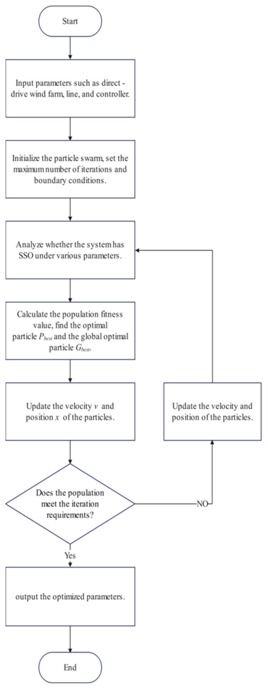
The PSO algorithm uses the current position and velocity of particles to find the optimal value in the population, continuously updating and iterating to seek the global optimum.
The integral of time multiplied by absolute error (ITAE) was selected as the objective function for PSO optimization because it penalizes long-duration errors more heavily, thereby emphasizing fast convergence and effective damping—both critical for SSO suppression. Alternative indices such as IAE (integral of absolute error) or ISE (integral of squared error) could also be used; however, ITAE is known to produce responses with smaller settling time and overshoot [23], making it particularly suitable for oscillation suppression problems.
During the PSO optimization, the search space for the three parameters was constrained within empirically determined bounds to ensure stability and practical feasibility: kp ∈ [500, 5000], β1 ∈ [100, 10,000], and β2 ∈ [1 × 10⁶, 1 × 10⁸]. These ranges were selected based on preliminary simulations and in references [23,24] to avoid unstable or excessively oscillatory behavior. The PSO parameters (population size K = 30; inertia weight w = 0.9; maximum iterations I = 40) were selected based on common practice in power system applications [23]. A preliminary sensitivity study indicated that increasing population size beyond 30 or iterations beyond 40 yielded marginal improvement in ITAE (<5%) at significantly higher computational cost, while decreasing these values led to degraded optimization results. Therefore, the chosen parameters provide a reasonable trade-off between optimization quality and computational efficiency.
Setting a particle swarm of a certain scale, with particle dimension D, maximum iteration number I, particle position X, particle velocity V, individual best position Pbest, and global best position Gbest, the velocity and position of the k-th particle in the d-th dimension at the i-th iteration are
where i = 1, 2, …, I; k = 1, 2, …, K; d = 1, 2, …, D; w is the inertia weight for adjusting the solution space; r1 and r2 are two random numbers between 0 and 1 to prevent the system from falling into local optima; c1 and c2 are individual and social learning factors, representing the maximum learning step size.
The PSO optimization flowchart is shown in Figure 2.
Figure 2.
PSO optimization flowchart.
It is important to note that the PSO optimization is performed offline during the controller design phase. Once the optimal parameters are obtained and deployed, the real-time computational burden of PSO-LADRC is identical to that of conventional LADRC, as both share the same control structure (LESO + PD controller). Therefore, the proposed method does not introduce additional online computational overhead.
3. Results
It should be noted that the proposed PSO-LADRC retains the same control structure as conventional LADRC (LESO + PD controller). The key difference lies in the parameter tuning approach: instead of relying on the empirical bandwidth method, the PSO algorithm is employed to optimize the controller parameters (kp, β1, and β2) for enhanced performance under weak grid conditions. As demonstrated in Table 1, this optimization yields significant improvements, namely, damping ratio increases of 303–444%, THD reductions of up to 72.5%, and settling time reductions of 57–60%, compared to bandwidth-tuned LADRC.
Table 1.
Control performance comparison under different grid conditions.
A wind farm including 110 direct-drive wind turbines is used for simulation verification. The main parameters of the direct-drive wind turbine grid connection and control system are shown in Table 2.
Table 2.
Direct-drive wind farm parameters.
The single-unit capacity is 1.5 MW, with a rated voltage of 0.69 kV. After two-stage transformer boosting, it is connected to a 110 kV transmission line for long-distance transmission, where the wind turbine, generator, and machine-side converter are equivalent to a controlled current source. Assuming that the operating conditions of each wind turbine are basically the same, an equivalent aggregated model can be established, with all units equivalent to a single direct-drive wind turbine.
PSO-LADRC has three parameters to be optimized, so D = 3. Let w = 0.9; I = 40; K = 30; c1 = c2 = 2; the integral of time multiplied by absolute error is used as the optimization performance evaluation index.
The short circuit ratio (SCR) is an index for grid strength. A grid with SCR ≤ 3 is defined as weak, while SCR ≤ 2 indicates an extremely weak grid [22]. In simulation studies, the point-of-common-coupling (PCC) SCR can be adjusted by changing the inductance value Lg of the AC grid line. The physical meaning of this is that a larger line inductance represents a longer transmission distance or a weaker connection to the main grid, resulting in a lower SCR. By varying Lg to achieve different SCR values, we can simulate changes in grid strength and systematically investigate the conditions under which SSO occurs and how effectively different controllers can suppress it.
3.1. Theoretical Stability Margin Analysis in Weak Grids
To comprehensively evaluate the robustness of the proposed control approach across various grid strengths, a small-signal theoretical framework linking the controller parameters to the system stability margins is established.
The dynamic interaction between the grid-side converter and the weak grid can be analyzed using the impedance-based stability criterion. The system stability is determined by the impedance ratio , where represents the grid impedance and is the equivalent output impedance of the converter under current-loop control.
For the first-order LADRC, the equivalent closed-loop characteristic equation integrating the LESO and the PD control law can be derived from Equations (2) and (3). The robustness of the system is highly dependent on the roots of the characteristic equation:
In traditional bandwidth-based tuning, the parameters are strictly constrained by . As the grid becomes extremely weak (e.g., SCR = 1.5; ), the equivalent grid impedance increases significantly, causing the phase margin of the system to degrade, eventually pushing the dominant poles into the right-half plane (RHP), leading to SSO.
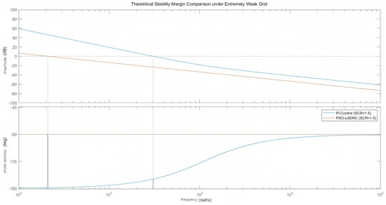
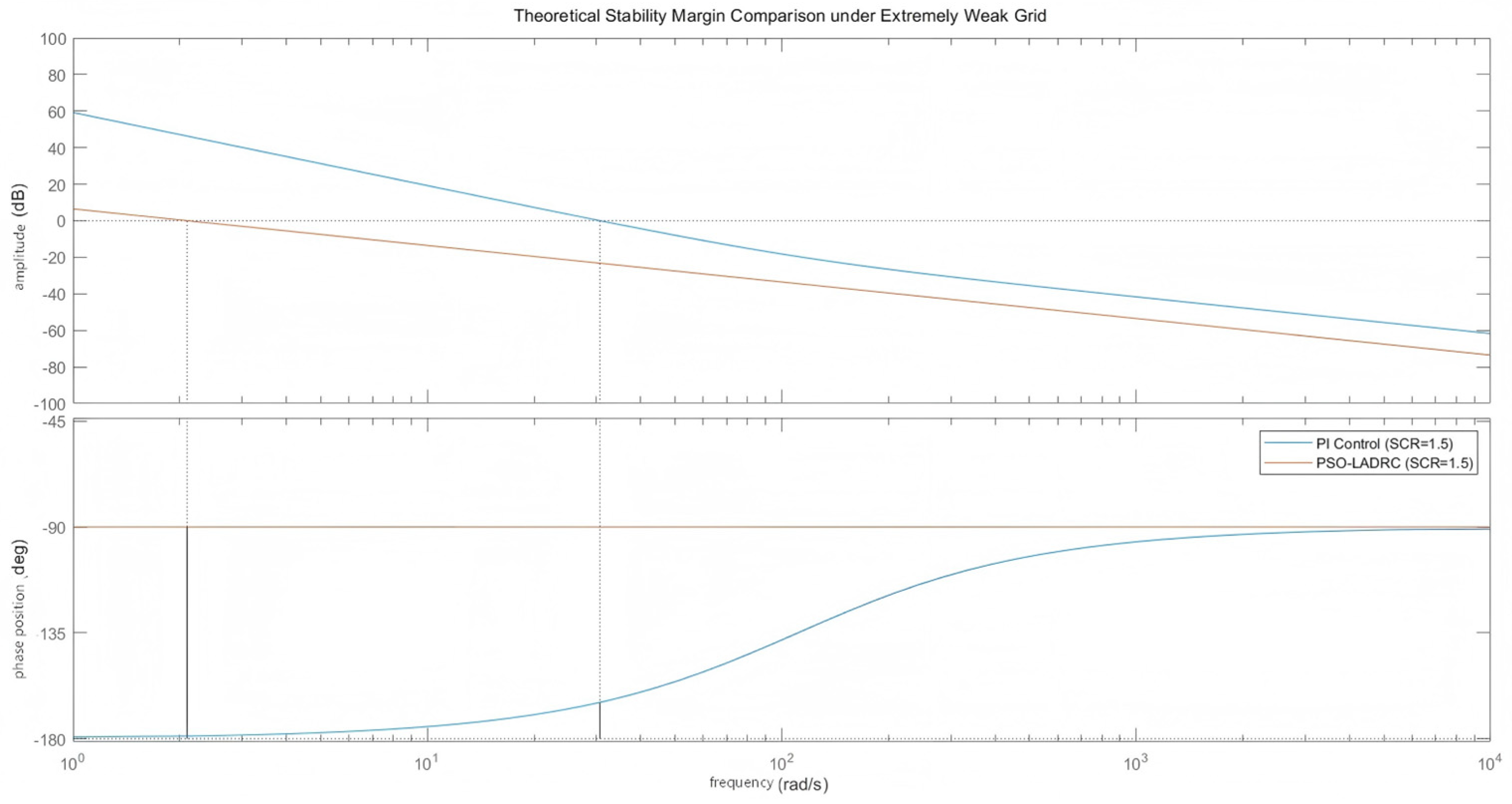
The PSO algorithm systematically optimizes the LADRC parameters () to maximize the system’s damping ratio based on the ITAE objective. Theoretically, these optimized parameters dynamically reshape the equivalent output impedance . As demonstrated in the Bode plot analysis (Figure 3), while the PI-controlled system loses its phase margin and becomes unstable under the extremely weak grid condition (SCR = 1.5), PSO-LADRC successfully maintains an ideal phase margin of approximately 90°. This provides a solid theoretical phase margin that guarantees stability, perfectly corroborating the time-domain simulation results presented in Section 3.2.
Figure 3.
Theoretical Bode plot comparison of open-loop transfer functions under extremely weak grid (SCR = 1.5).
3.2. Comparative Analysis of SSO Suppression in Weak Grids
The line inductance Lg is a critical parameter that directly determines grid strength characteristics. According to IEEE Standard 1204 and IEC 61400-21, the relationship between line inductance and grid strength can be expressed as:
where Ssc is the short-circuit capacity, Sn is the rated capacity of the wind farm (165 MW for 110 × 1.5 MW units), Ug is the grid voltage (110 kV), and ω is the angular frequency (314 rad/s).
Based on this relationship, three representative Lg values were selected to cover the range from weak to extremely weak grid conditions:
- Lg = 0.07 H → SCR = 2.5 (weak grid);
- Lg = 0.081 H → SCR = 2.1 (weaker grid);
- Lg = 0.11 H → SCR = 1.5 (extremely weak grid).
These values represent practical scenarios where sub-synchronous oscillations are most likely to occur in actual wind farm operations. The selected range encompasses typical weak grid conditions found in remote wind farm installations with long transmission lines.
To quantitatively evaluate the suppression effectiveness under different grid strengths, the following performance metrics are measured for each Lg value and control method, as shown in Table 1.
From Table 1, it can be observed that
- As grid strength decreases (Lg increases), the damping ratio of traditional PI control becomes increasingly negative, indicating more severe oscillations;
- LADRC with bandwidth-based parameter tuning provides positive damping only under moderate weak grid conditions (SCR ≥ 2.1);
- PSO-LADRC maintains positive damping across all tested conditions, with damping ratio improvement of 303% compared to bandwidth-LADRC at SCR = 2.5 (0.125 vs. 0.031) and 444% at SCR = 2.1 (0.098 vs. 0.018), and maintaining stability where others fail at SCR = 1.5;
- THD reduction with PSO-LADRC reaches 72.5% compared to PI control at SCR = 2.5 (4.2% vs. 15.3%), demonstrating superior harmonic suppression;
- Settling time is reduced by 57% at SCR = 2.5 (1.2 s vs. 2.8 s) and 60% at SCR = 2.1 (1.8 s vs. 4.5 s) compared to bandwidth-tuned LADRC.
In simulation studies, the point-of-common-coupling (PCC) SCR can be adjusted by changing the inductance value Lg of the AC grid line to simulate changes in grid strength and investigate whether SSO occurs in weak grids. The detailed simulation results under different SCR conditions are presented below.
The short circuit ratio (SCR) is an index for grid strength. A grid with SCR ≤ 3 is defined as weak, while SCR ≤ 2 indicates an extremely weak grid [22]. In simulation studies, the point-of-common-coupling (PCC) SCR can be adjusted by changing the inductance value Lg of the AC grid line to simulate changes in grid strength and investigate whether SSO occurs in weak grids.
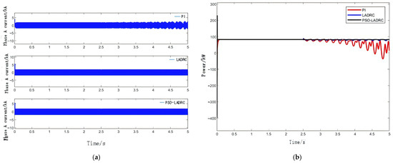
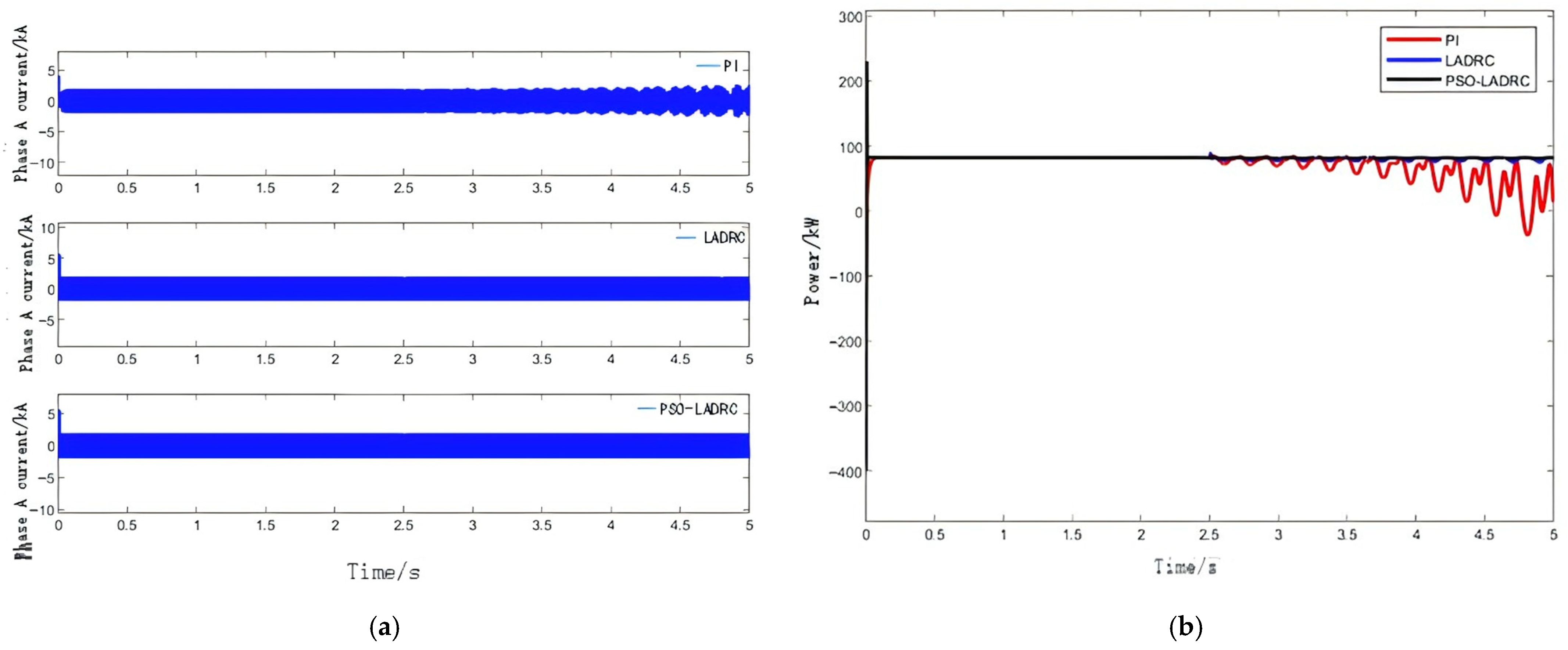
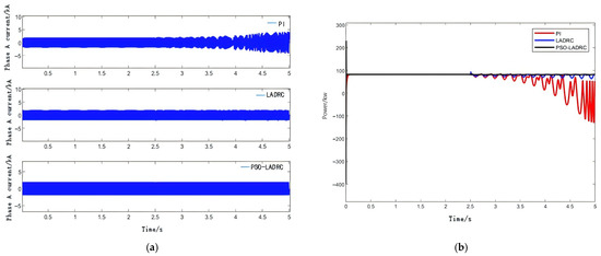
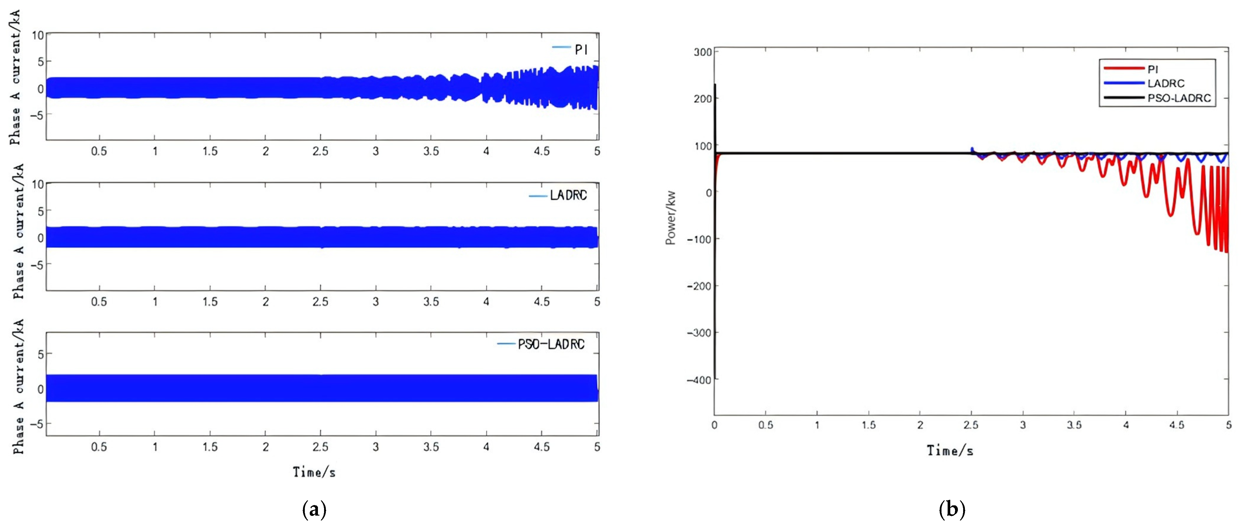
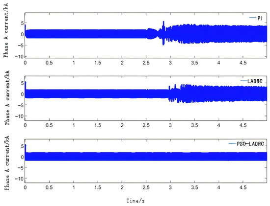
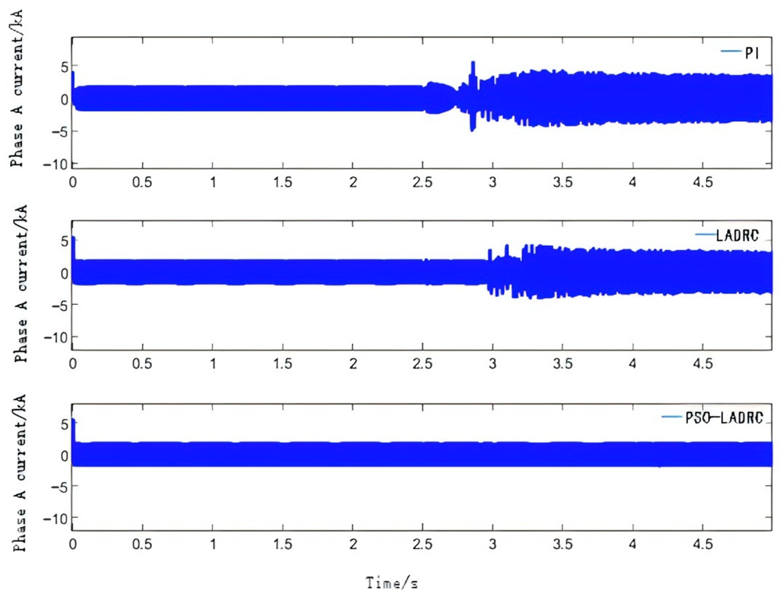
(1) At t = 2.5 s, the line inductance Lg = 0.07 H is switched in, resulting in a short circuit ratio (SCR) of 2.5. The response curves of the PCC phase A current Ia and power P under the three control methods of traditional PI, LADRC, and PSO-LADRC are shown in Figure 4. Figure 4a shows the variation curve of A-phase current (Ia) under the three methods, and Figure 4b displays the variation curve of power P.
Figure 4.
(a) Ia change curves under three control methods. (b) Power curves under three control methods.
(2) At t = 2.5 s, the line inductance Lg = 0.81 H is switched in, resulting in a short circuit ratio (SCR) of 2.1. Simulation results show that the response curves of A-phase current (Ia) and power (P) under the three control strategies in this state are obtained, as illustrated in Figure 5.
Figure 5.
(a) Ia change curves under three control methods. (b) Power curves under three control methods.
From Figure 4 and Figure 5, it can be seen that in weak grids, current and power exhibit oscillatory phenomena, with reduced SCR exacerbating oscillations. Using traditional PI control, the active power and current output by the grid-side converter show increasingly obvious oscillations; under LADRC and PSO-LADRC control, the current and power waveforms are stable, indicating that LADRC can suppress SSO under weak grid conditions.
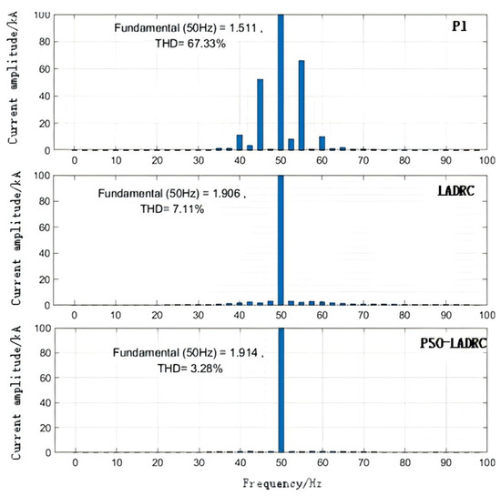
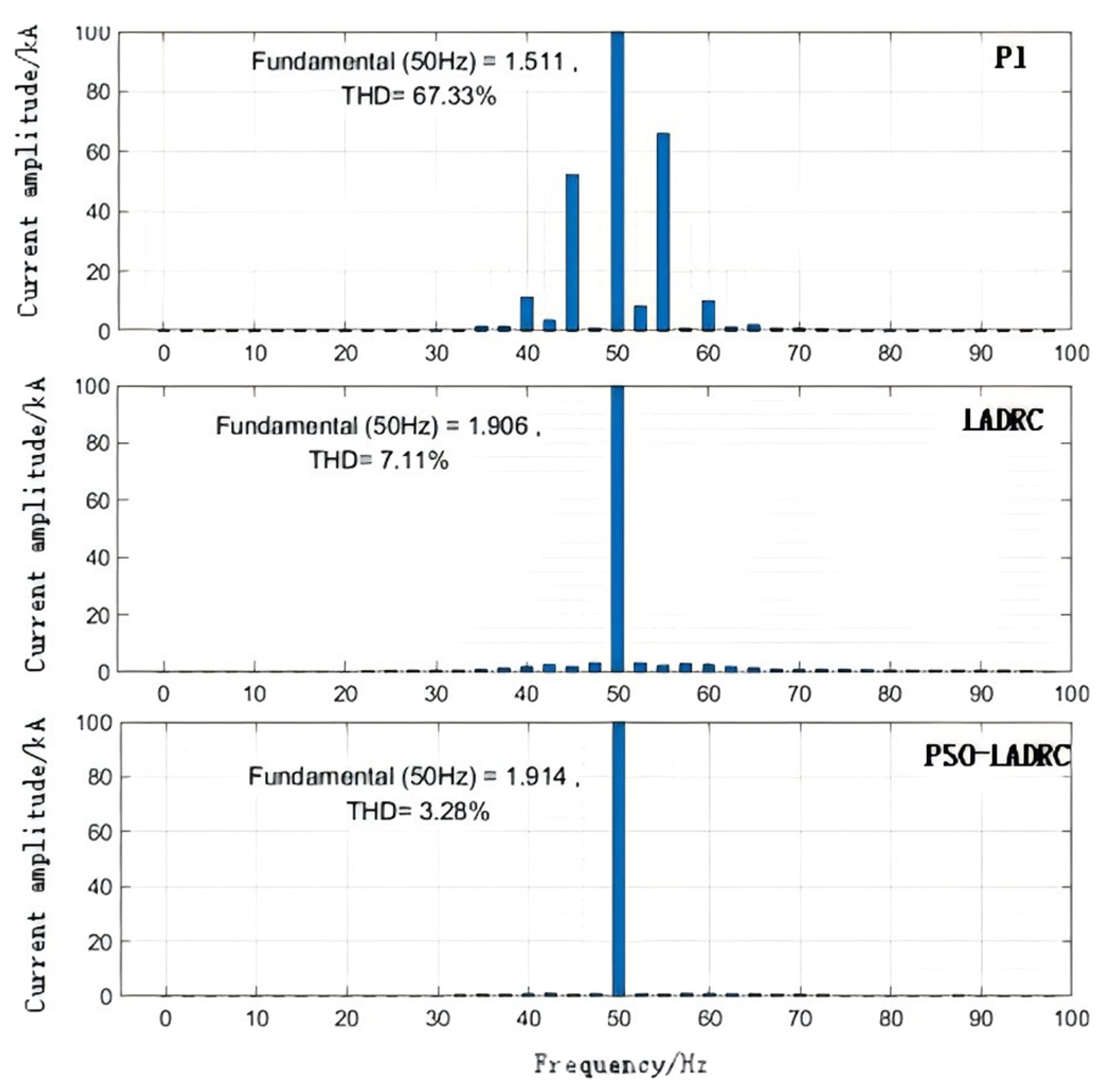
To further illustrate the results, an FFT analysis of A-phase current Ia under SCR = 2.1 is performed using three control methods, with the results shown in Figure 6. It can be seen that the fundamental current (50 Hz in the Figure 6) using PI control is the smallest, and the total harmonic distortion (THD) is the largest, while PSO-LADRC control has the largest fundamental current and the smallest THD, indicating effective SSO suppression under PSO-LADRC control.
Figure 6.
Analysis of Ia Fast Fourier Transform with SCR = 2.1.
3.3. Adaptability Analysis
To verify the adaptability of LADRC, simulations are conducted under extremely weak grid and short circuit conditions. Only the change curves of the PCC current Ia are given here, as the power curves are similar.
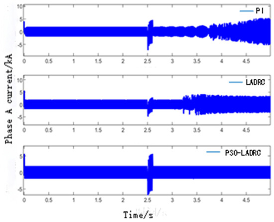
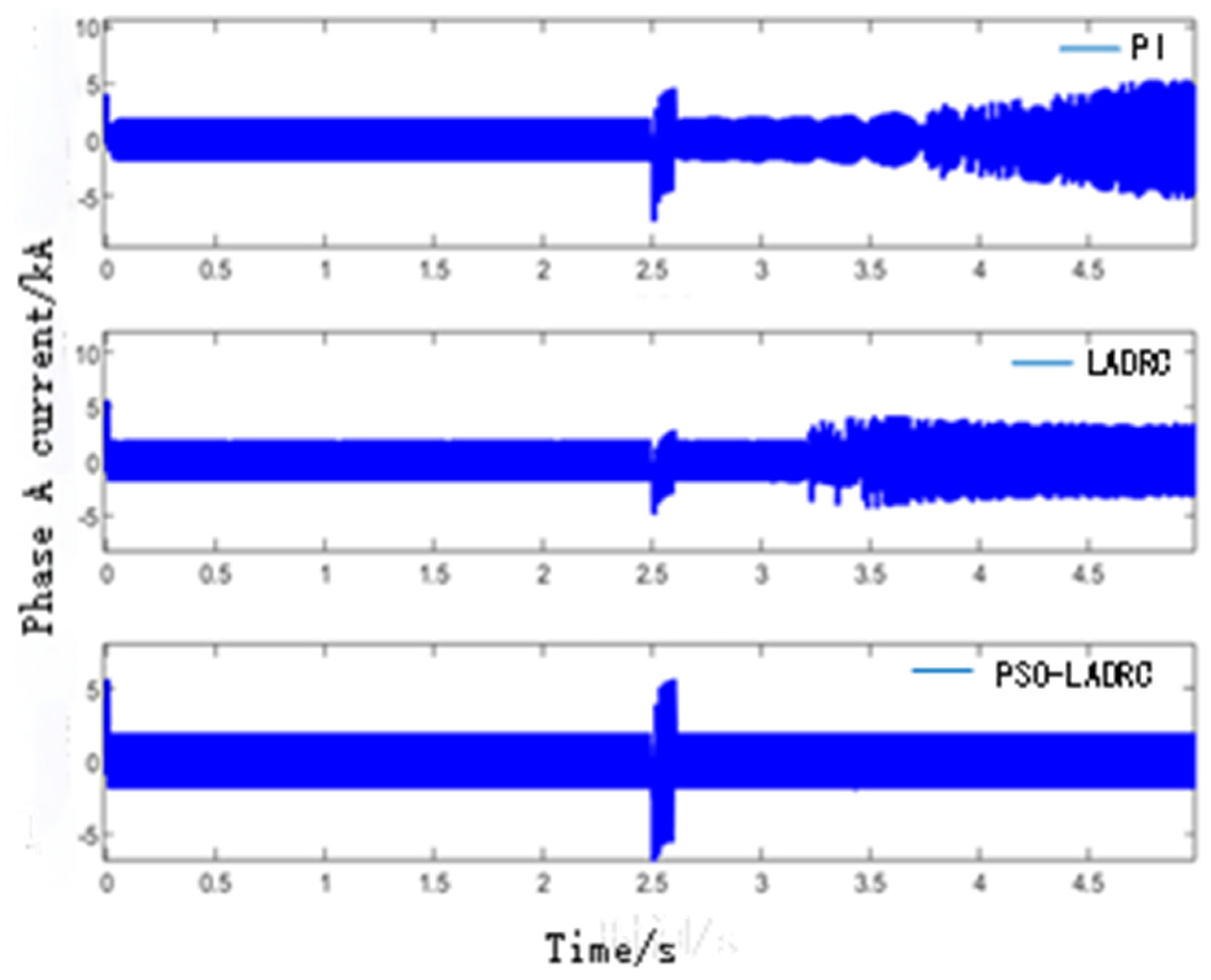
Extremely weak grid condition: At 2.5 s, the grid inductance Lg = 0.11 H is switched in, and the calculated SCR is 1.5, representing an extremely weak grid. At this time, the system is in a highly unstable state, and the response curve of the PCC current Ia is shown in Figure 7.
Figure 7.
Ia curve with SCR = 1.5.
As seen in Figure 7, under PI and traditional LADRC control, the current oscillates violently after 2.5 s, with the system unstable and SSO occurring, indicating that LADRC cannot suppress oscillations under extremely weak conditions; under PSO-LADRC control, the current waveform is stable, showing that this control method can still suppress oscillations under extremely weak conditions.
Short circuit condition: At 2.5 s, during steady-state system operation, a phase A single-phase ground fault occurs on the high-voltage side of the 35 kV/110 kV line transformer, lasting 50 ms. Figure 8 shows the dynamic response curve of the 110 kV line phase A current Ia.
Figure 8.
Current curve under phase A short circuit.
As seen in Figure 8, the phase A current under PSO-LADRC control stabilizes after a transient process of about 0.1 s without SSO, while both PI and traditional LADRC control exhibit oscillations, indicating that PSO-LADRC can suppress SSO under short circuit conditions.
The above simulation results show that when operating conditions change or faults occur, LADRC has the ability to limit the propagation of sub-synchronous components. The proposed PSO-LADRC has stronger adaptability than traditional LADRC, effectively suppressing SSO.
To further evaluate robustness against operating point variations, additional simulations were performed at 60% and 80% of rated power under SCR = 2.1. PSO-LADRC maintained stable operation with THD < 6% in all cases, whereas PI control exhibited THD > 12% and persistent oscillations. These results suggest that the proposed control parameters remain effective across a range of operating conditions.
In practical implementations, factors such as converter switching delays, discretization effects, and measurement noise may affect controller performance. While a detailed analysis of these non-idealities is beyond the scope of this work, the inherent robustness of LADRC [12] provides a degree of tolerance against such disturbances. Preliminary tests with added measurement noise (SNR = 30 dB) showed that PSO-LADRC maintained stable operation with only marginal increase in THD (<1%), indicating promising robustness. Future work will include hardware-in-the-loop testing to validate performance under realistic conditions.
4. Discussion
This study adopts an aggregated wind farm model based on the assumption that all turbines operate under similar conditions, which is a common practice in initial SSO studies [22]. However, in reality, parameter dispersion among turbines (e.g., slight variations in filter inductance or control parameters) may influence SSO characteristics. While a detailed multi-machine analysis is beyond the scope of this work, the proposed controller’s robustness against parameter variations is partially evidenced by its strong performance under various grid strengths and fault conditions (Section 3.2 and Section 3.3). Future work will extend the validation to multi-machine models to further confirm the controller’s effectiveness under parameter dispersion.
The connection of direct-drive wind turbines to weak AC grids may induce SSO, which can seriously affect the stable operation of the power system. To solve this problem, this paper proposes and validates a PSO-optimized LADRC strategy for the current inner loop of grid-side converters.
5. Conclusions
The key findings and conclusions are as follows:
The primary advantage of this research approach lies in its systematic handling of a complex control problem. First, by adopting LADRC, the method inherently provides strong robustness against the internal and external disturbances that characterize weak grid conditions, effectively blocking the propagation path of sub-synchronous frequency components—a task at which traditional PI controllers often fail. Second, and most critically, the integration of the particle swarm optimization (PSO) algorithm directly addresses the known difficulty of tuning LADRC parameters. The results confirm that the PSO-tuned controller (PSO-LADRC) not only simplifies the parameter design process but also delivers superior performance. It exhibits stronger adaptability across a wide range of operating conditions—including extremely weak grids (SCR = 1.5) and fault scenarios—compared to LADRC tuned by the conventional bandwidth method. This adaptability is a clear and demonstrable advantage over both traditional PI control and standard LADRC, ensuring consistent SSO suppression without the need for exhaustive manual recalibration.
The implications for the field of renewable energy integration are significant. In practice, this research provides a viable and effective control strategy to enhance the grid-connected stability of large-scale wind farms, particularly as they are increasingly built in remote areas with weak grid connections. By reliably suppressing SSOs, this approach can help prevent power outages, reduce mechanical and electrical stress on turbine components, and minimize associated maintenance costs. The expectation is that this PSO-LADRC method, or similar optimization-based tuning approaches, can be deployed in real-world wind turbine controllers. This would enable wind farms to operate more stably, support grid operators in maintaining a secure power system with a high penetration of inverter-based resources, and potentially increase the hosting capacity of weak AC grids for renewable energy generation.
Author Contributions
Conceptualization, H.-Y.H. and M.-D.W.; methodology, H.-Y.H.; software, H.-Y.H.; validation, H.-Y.H., H.-Y.X. and S.-Y.W.; formal analysis, H.-Y.H.; investigation, H.-Y.H.; resources, M.-D.W.; data curation, H.-Y.H.; writing—original draft preparation, H.-Y.H.; writing—review and editing, M.-D.W., H.-Y.X. and S.-Y.W.; visualization, H.-Y.X.; supervision, M.-D.W.; project administration, M.-D.W.; funding acquisition, M.-D.W. All authors have read and agreed to the published version of the manuscript.
Funding
This research received no external funding.
Institutional Review Board Statement
Not applicable.
Informed Consent Statement
Not applicable.
Data Availability Statement
The data presented in this study are available on request from the corresponding author due to confidentiality agreements.
Conflicts of Interest
Author Hua-Yang Xu was employed by the XJ Protection & Automation System Company. Author Su-Yang Wang was employed by the China Railway Signal & Communication Low-Altitude Intelligence Technology Co., Ltd. The remaining authors declare that the research was conducted in the absence of any commercial or financial relationships that could be construed as a potential conflict of interest.
References
- Wang, L.; Xie, X.; Jiang, Q.; Liu, H.; Li, Y.; Liu, H. Investigation of SSR in practical DFIG-based wind farms connected to a series-compensated power system. IEEE Trans. Power Syst. 2015, 30, 2772–2779. [Google Scholar] [CrossRef] [Scilit]
- Zhang, X.; Xie, X.; Shair, J.; Liu, H.; Li, Y.; Li, Y. A grid-side sub-synchronous damping controller to mitigate unstable SSCI and its hardware-in-the-loop tests. IEEE Trans. Sustain. Energy 2020, 11, 1548–1558. [Google Scholar] [CrossRef] [Scilit]
- Wang, Y.; Wang, X.; Liao, J.; Wang, H. Review of Generation, Identification and Suppression of Wide-band Oscillation in AC-DC Power System. High Volt. Eng. 2023, 49, 3148–3162. [Google Scholar]
- Xiao, X.; Luo, C.; Liao, K. Review of the Research on Subsynchronous Oscillation Issues in Electric Power System with Renewable Energy Sources. Trans. China Electrotech. Soc. 2017, 32, 85–97. [Google Scholar]
- Zhang, T.; Wang, H. Research methods for subsynchronous oscillation induced by wind power under weak AC system: A review. Power Syst. Prot. Control 2021, 49, 177–187. [Google Scholar]
- Yu, H. Research on grid connected sub synchronous oscillation of doubly fed wind turbines. J. Power Supply 2016, 14, 147–151. [Google Scholar]
- Xie, X.; Liu, H.; He, J.; Zhang, C.; Qiao, Y. Mechanism and characteristics of subsynchronous oscillation caused by the interaction between full-converter wind turbines and AC systems. Proc. CSEE 2016, 36, 2366–2372. [Google Scholar]
- Lv, D.; Xu, H.; Ma, Q.; Wang, L.; Wu, X. Analysis of Sub-synchronous oscillation mechanism of direct drive converter connected to Weak Power Grid. Acta Sol. Energy Sin. 2021, 42, 423–429. [Google Scholar]
- Song, R.; Guo, J.; Li, B.; Zhou, P.; Du, N.; Yang, D. Mechanism and Characteristics of Subsynchronous Oscillation in Direct-Drive Wind Power Generation System Based on Input-Admittance Analysis. Proc. CSEE 2017, 37, 4662–4670+4891. [Google Scholar]
- Xu, Y.; Cao, Y. Research on Mechanism of Sub/Sup-Synchronous Oscillation Caused by GSC Controller of Direct-Drive Permanent Magnetic Synchronous Generator. Power Syst. Technol. 2018, 42, 1556–1564. [Google Scholar]
- Ren, B.; Du, W.; Wang, H. Influence of PLL control on sub-synchronous oscillation stability of grid-connected PMSG: Control parameter safety region. Electr. Power Autom. Equip. 2020, 40, 142–149. [Google Scholar]
- Han, J. Auto Disturbances Rejection Control Technique. Front. Sci. 2007, 1, 24–31. [Google Scholar]
- Gao, B.; Yi, Y.; Shao, B.; Wang, F.; Zhao, S. Subsynchronous oscillation mitigation strategy based on ADRC for D-PMSGs based wind farm. Electr. Power Autom. Equip. 2020, 40, 148–157. [Google Scholar]
- Gao, B.; Hu, Y.; Li, R.; Yao, L.; Zhao, S. on sub-synchronous control interaction mitigation strategy based on active disturbance rejection control for doubly-fed induction generator. Power Syst. Technol. 2019, 43, 655–664. [Google Scholar]
- Cai, W.; Guo, K.; Liu, L. Sub-synchronous oscillation mitigation strategy based on first-order LADRC for direct drive wind turbines. Electr. Power 2022, 55, 175–184. [Google Scholar]
- Miao, M. Subsynchronous Oscillation suppression of wind power based on STATCOM. Electr. Drive 2018, 48, 53–58. [Google Scholar]
- Chen, Y. Control Strategy of Grid-Connected Converters of Wind Power System Based on Improved Active Disturbance Rejection Control. Master’s Thesis, Tianjin University of Technology, Tianjin, China, 2021. [Google Scholar]
- Li, B.; Guo, K.; Lv, J. Research on Subsynchronous Vibration Suppression of Direct Drive Fan by Improved LADRC in Weak Current Network. Electr. Power China 2023, 56, 56–67. [Google Scholar]
- Zhao, W.; Cui, C.; Yan, G. Equivalent model of direct drive wind farm for subsynchronous oscillation analysis. Smart Electr. Power 2022, 50, 22–28, 68. [Google Scholar]
- Li, J.; Bi, T.; Yu, Z.; Zhang, P.; Xiao, S. Study on response characteristics of grid converter control system of permanent magnet synchronous generators(PMSG) to subsynchronous frequency component. Power Syst. Technol. 2017, 41, 1734–1740. [Google Scholar]
- Wu, W.; Cai, Y.; Lan, X. Discrete modeling and stability control of linear active disturbance rejection control for three-level neutral point clamped converer. Trans. China Electrotech. Soc. 2020, 35, 37–48. [Google Scholar]
- Fernandez, L.M.; Jurado, F.; Saenz, J.R. Aggregated dynamic model for wind farms with doubly fed induction generator wind turbines. Renew. Energy 2008, 33, 129–140. [Google Scholar] [CrossRef] [Scilit]
- Ma, M.; Liao, P.; Cai, Y.X.; Lei, R.T.; He, Y. First-order active disturbance rejection control for LCL grid-connected inverters and control parameter tuning method based on particle swarmoptimization. Electr. Power Autom. Equip. 2021, 41, 174–182. [Google Scholar]
- Zheng, F.; Wu, G.; Lin, X.; Zheng, S.; Wu, X.; Lin, Y.; Deng, C. Research on control strategy for improving stability of multi-inverter parallel system under weak grid condition. Int. J. Electr. Power Energy Syst. 2023, 153, 109121. [Google Scholar] [CrossRef] [Scilit]

Disclaimer/Publisher’s Note: The statements, opinions and data contained in all publications are solely those of the individual author(s) and contributor(s) and not of MDPI and/or the editor(s). MDPI and/or the editor(s) disclaim responsibility for any injury to people or property resulting from any ideas, methods, instructions or products referred to in the content. |
© 2026 by the authors. Licensee MDPI, Basel, Switzerland. This article is an open access article distributed under the terms and conditions of the Creative Commons Attribution (CC BY) license.